topic 9: building blocks for computers
TRANSCRIPT

Topic 9: Building Blocks for Computers
Readings for this topic:
P&H, Appendix B.3 thru B.6
Goal•Summary of combinatorial and sequential components that are useful forcomputers.•Techniques for combining them

Recall: Full Adder
Boo:lean Algebra

Bit Slice Adders
Problem: How to add 3 bit numbers?•C2C1C0 = A2A1A0+ B2B1B0•Redesigning circuit for 6 inputs would be messy and wouldn't scale well.
Solution: Cascade 1-bit adders
1111110011101010100110110
101011000000
ContSumCinBA

Adder bit slice
This is called a "full adder".•A "half adder" adds two bits and produces sum and carry out

Bit-slice Adder
Problem: Time to compute carry grows with number of inputs
Solution: Carry look ahead adders.
•shortcut the carry from previous group of bits to following group of bits•How: using local group of bits, determine:•generate: group will always generate carry into next group•kill: group will never generate carry into next group•propagate: group will propagate carry from previous group into next

Shifters
Shifts 1 bit left/right, based on input: 1 => shift left, 0 => shift right

Multiplexer
Given an n-bit number as input, select one of 2n inputs.
AND gate passes signal through if the control is 1

Full Shifter
Shift N-bit number N positions in one direction
Can build a shifter with multiplexors
Example: 4-bit right-shifter
Example: to make full 32-bit shifter, use 3 stages:•stage1: shift by 0, 8, 16, or 24•stage2: shift by 0, 2, 4, or 6•stage3: shift by 0, or 1

ALU
Summary: we can do shifters, adders, AND, OR, NOT, XOR, ...•Arithmetic operations generate a carry•Logic operations have no carry
An ALU computes a function of 2 inputs O = F(A, B),where the function F is selected by other inputs (F0, F1).
•Bit Slicing: Compute function for 1 bit using carry in and carry out.This is just a generalization of cascaded adders.

An example ALU
A + B11NOT B10A OR B01A AND B00FunctionF
Circuit Symbol

Decoders
How do we select an operation?
Decoder: given an n-bit number as input, enables one of 2n outputs

ALU Bit Slice Schematic
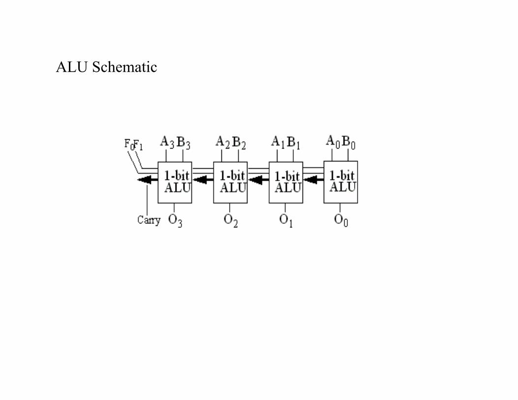
ALU Schematic
Subtraction
Add: input A and B, Cin=0
Subtract: input A and B, Cin=1
How come? remember two's complement...

Building Registers
Abstraction:•Inputs: data[N], clock, write-enable•Output: data[N]
Using D Flip-flops, we almost get it (e.g., 8 bit register):
Problem: How do we do write-enable?

N-bit Registers
Implementing write-enable
Solution 1: Gate clock.
What are the problems with this solution?

N-bit Registers
Solution 2: Use multiplexor (MUX):
By connecting together N of the writable D Flip-flops, N bit register can beimplemented.
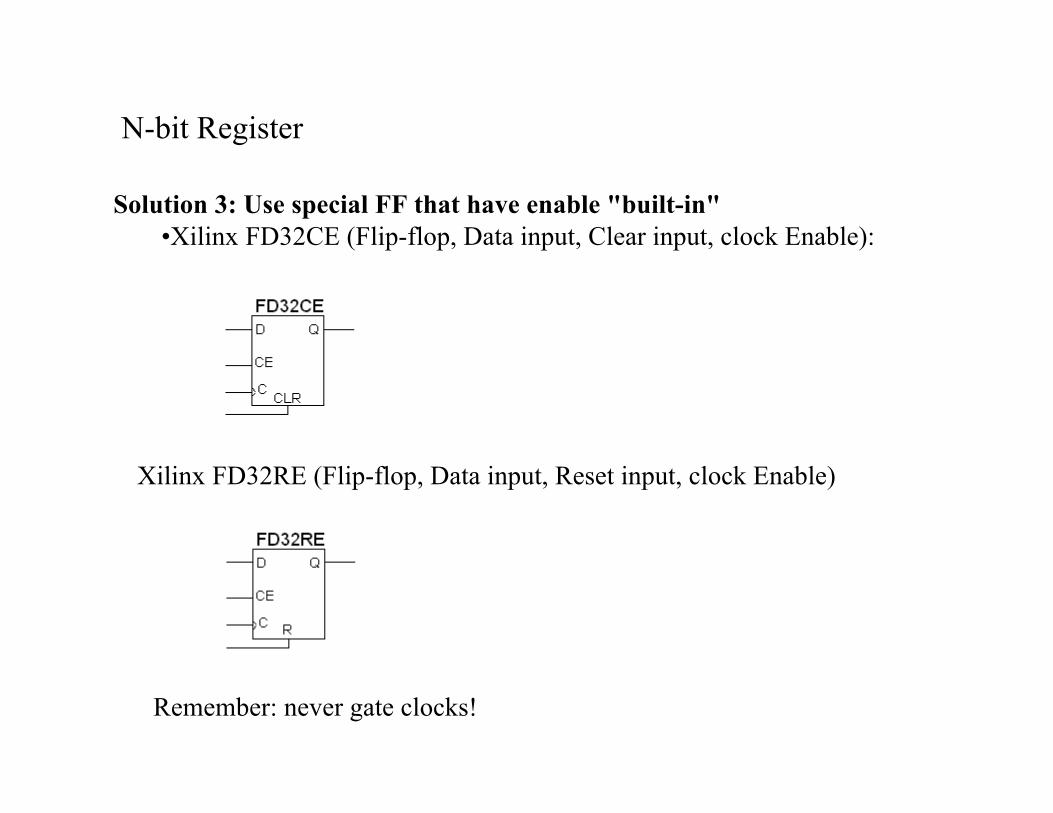
N-bit Register
Solution 3: Use special FF that have enable "built-in"•Xilinx FD32CE (Flip-flop, Data input, Clear input, clock Enable):
Xilinx FD32RE (Flip-flop, Data input, Reset input, clock Enable)
Remember: never gate clocks!

Register Files
Abstraction•holds 2M (e.g., M=4, 24=16) registers.•Inputs: Register Number [M], Din [N], Clock, Write-enable•Outputs: Dout[N]
Example:•Addr=0011, W=0Dout = Reg[3]•Addr=0101, W=1, Din=0xFFReg[5] = 0xFF at clock

Register File with mux
How to select a register

Tri-state outputs
Tri-state outputs can also be off ("disabled", on: "enabled")
Normal outputs can be 0 or 1
This allows many outputs to be wired together•as long as only one is enabled at a time!

Register File with tri-state
Hint: For HOT314 we will implement the register file using a RAM.

What goes in a RAM?
Example: 128 x 1-bit memory (128=8*16)

SRAM Cells
6-T static RAM cell
Read:•pull bit + bit to Vcc•pull 1 row select high•cell pulls bit or bit low•sense amp detects differential signal between bit and bit
Write:•pull 1 row select high•drive bit and bit to flip cell

DRAM Cells
1-T dynamic RAM cell
Read:•pull bit Vcc/2•pull 1 row select high•cell "nudges" bit low or high•sense amp detects difference to a reference bit line
Write:•pull 1 row select high•drive bit line to charge/discharge capacitor