topic 1- motors and generators
TRANSCRIPT
hscintheholidays.com.au All Rights Reserved. Page 1 of 18
Topic 1-Motors and Generators
HSC Physics Notes 2011-2012

hscintheholidays.com.au All Rights Reserved. Page 2 of 18
Dot point Notes
1.1 Motors use the effect of forces on current-carrying conductors in magnetic fields
-The motor effect theory:
A conductor carrying a current across a magnetic field will experience a force
-Parallel current-carrying conductors:
Currents in the same direction attract
-Torque
-Current loops -Applications of the motor effect:
Galvanometer
Loudspeaker -DC motors:
A DC motor contains a rotating coil, magnets and a split ring commutator
1.1.1 Discuss the effect on the magnitude of the force on a current-carrying conductor of variations in:
The strength of the magnetic field in which it is located
The magnitude of the current in the conductor
The length of the conductor in the external magnetic field
The angle between the direction of the external magnetic field and the direction of the length of the conductor
Increase in any of these factors will increase the force on a current-
carrying conductor because they are all directly proportional to force
1.1.2 Describe qualitatively and quantitatively the force between long parallel current-carrying conductors:
Parallel current-carrying conductors:
PCCC exert a force on each other because each carries a current through the magnetic field generated by the other
If two straight conductors carry electric currents in the same direction, then they will experience a force towards each other (attraction)
If two straight conductors carry electric currents in the opposite direction, then they will experience a force away from each other (repulsion)
1.1.3 Define torque as the turning moment of a force using:
Torque:
A conductor carrying a current in a magnetic field experiences a

hscintheholidays.com.au All Rights Reserved. Page 3 of 18
force. If it is a turning force then this turning effect is torque
Torque is a measure of the turning effect of a force on a spinning drive shaft or rotor
1.1.4 Identify that the motor effect is due to the force acting on a current-carrying conductor in a magnetic field
The motor effect:
A current carrying conductor will experience a force in a magnetic field
Direction of force can be found using right hand palm rule (i.e. fingers point to direction of magnetic field, thumb points in the direction of current flow and palm faces the direction of the force)
Calculate force by using:
Max. force at 90°, min. force at 0°
1.1.5 Describe the forces experienced by a current-carrying loop in a magnetic field and describe the net result of the forces
Torque and a current-carrying loop: Each long side of the coil experiences a force whose magnitude
does not change throughout a rotation of the coil, since the sides always remain perpendicular to the field. The force on each long side can be shown (RHPR) to be always in the same direction, opposite in direction to the force on the other long side, and always perpendicular to the axis.
Each end of the coil will experience a force which varies from zero, when the plane of the coil is parallel to the field, to a maximum when the plane of the coil is perpendicular to the field. The forces on the two ends can be shown (RHPR) to be opposite in direction, always parallel to the axis, and alternating in direction through a full rotation of the coil.
The force on each long side produces a torque about the axis. As the forces are in opposite directions, and their lines of action are on opposite sides of the axis, they produce a torque in the same
direction i.e. As the forces on the two ends are always opposite in direction, and
always parallel to the axis, their net effect is zero. A current-carrying loop orientated in a plane at right angles to a
magnetic field will experience no net force.
If there are n loops then the formula is
If at an angle, the formula is
1.1.6 Describe the main features of a DC electric motor and the role of each feature
Stator:
Stationary parts of motor
Connected to the frame of the machine
Provides the external magnetic field in which the rotor rotates Rotor:
Armature and coil
Rotates about the axis of the motor shaft
Mounted on bearings that are attached to the frame of the motor DC motor:

hscintheholidays.com.au All Rights Reserved. Page 4 of 18
Rotor: in most practical motors, there are a number of coils wrapped around an armature. It experiences torque causing the armature to move.
Magnets: can be either permanent or electromagnets. They provide the direction of the magnetic field.
Armature: turning part of the motor and is the framework for the coils. The armature consists of a laminated soft iron cylinder and the coils are arranged at angles to each other.
Brushes: provides the current to the motor
Commutator: allows the armature to keep rotating in the same direction by reversing the current flow every half-cycle
1.1.7 Identify that the required magnetic fields in DC motors can be produced either by current-carrying coils or permanent magnets
DC motor:
An electric motor is a device that transforms electrical potential energy into rotational kinetic energy. The rotational motion is produced by passing a current through a coil in a magnetic field.
1.1.12 Identify data sources, gather and process information to qualitatively describe the application of the motor effect in:
The galvanometer The loudspeaker
The galvanometer:
A device used to measure the magnitude and direction of small DC currents.
Consists of many loops of wire and it is connected in series
When current flows through it, the coil experiences a force due to the presence of the external magnetic field (motor effect)
Needle is rotated until the magnetic force acting on the coil is equalled by a counter-balancing spring
Uses radial magnetic field so that the plane of the coil is always parallel to the magnetic field
The Loudspeaker:
Transforms electrical energy into sound energy
Consists of a circular magnet that has one pole on the outside and the other on the inside
Coil of wire (voice coil) sits in the space between the poles and is connected to the output of the amplifier
Amplifier provides current and changes direction at the same frequency as the sound that is being produced (change in direction will pull the coil in or out and can be determined by RHPR)
Voice coil vibrates in and out of the magnet by the motor effect
Voice coil is connected to a paper speaker cone that creates sound waves in the air as it vibrates

hscintheholidays.com.au All Rights Reserved. Page 5 of 18
Dot point Notes
1.2 The relative motion between a conductor and magnetic field is used to generate an electrical voltage
-Magnetic flux and flux density:
Flux density is magnetic field strength, B
Magnetic flux -Electromagnetic induction:
The generation of an emf in a conductor inside a magnetic field -Lenz’s Law:
An induced emf opposes the change that caused it
1.2.1 Outline Michael Faraday’s discovery of the generation of an electric current
Faraday Experiments: In 1820, Hans Christian Oersted and Andre Marie Ampere discovered
that an electric current produces a magnetic field. Faraday's ideas about conservation of energy led him to believe that since an electric current could cause a magnetic field, a moving magnetic field should be able to produce an electric current. Faraday demonstrated this in 1831.
Did experiments involving moving magnets in and out of coils
Found that current was induced in the coil
The magnitude of the current depended on how fast he moved the magnet
The direction of the current depended on whether he moved the magnet in or out
Direction also depends on which pole moved in or out
Experimented with two coils on one metal ring. Found that nothing happened when DC current flowed in ring 1, unless it was switched on and off quickly, there was a current induced in ring 2
Conclusions:
If there is relative movement between a conductor and a magnetic field, a potential difference is generated in the conductor
The magnitude of the potential difference is proportional to the rate at which the magnetic field is cut
1.2.2 Define magnetic field strength B as magnetic flux density
Magnetic field strength:
Magnetic field strength B (T) can also be expressed as magnetic flux density (Wb/m2 )
The closer they are the greater the magnetic flux density and vice versa
1.2.3 Describe the concept of magnetic flux density and surface area
Magnetic flux:
Φ (Wb) is the symbol for magnetic flux
Measures the amount of magnetic field passing through a given area
(tells us that if a particular area (A) is perpendicular to a uniform magnetic field strength (B), then the product gives the magnetic flux)
If area is parallel there is zero magnetic flux

hscintheholidays.com.au All Rights Reserved. Page 6 of 18
Dot point Notes
Since we know that , it can be rearranged so that i.e. magnetic flux density (can be measured in Wb/m2 or T)
1.2.4 Describe generated potential difference as the rate of change of magnetic flux through a circuit
Generating a potential difference:
Faraday found that the needle of the galvanometer only deflected when the magnet was moving
Gave rise to Faraday’s Law of Induction:
Law states that the size of an induced EMF is directly proportional to
the rate of change in magnetic flux
Negative sign indicates the direction of the induced emf
Electromagnetic induction is the creation of an emf in a conductor when it is in relative motion to a magnetic field, or is situated in a changing magnetic field (induced emf)
1.2.5 Account for Lenz’s Law in terms of conservation of energy and relate it to the production of back emf in motors
Lenz’s Law:
An induced emf always gives rise to a current that creates a magnetic field that opposes the original change in flux through the circuit
The Principle of Conservation of Energy states energy can neither be created or destroyed, but it can be transformed from one form to another
To create electrical energy in a coil, work must be done. Energy is required to move a magnet towards or away from a coil
Back emf is produced to counter the original change in magnetic flux
1.2.6 Explain that, in electric motors, back emf opposes the supply emf
Back emf in motors: Back emf is the emf induced in the coils of a motor as they spin in the
external magnetic field of the stator. By Lenz's law the direction of that induced emf opposes the emf
causing the motion of the armature. The current generated in the motor is an eddy current and opposes the supply emf . The net emf applied to the coils equals the supply emf minus the back emf.
The back emf increases as the speed of the motor increases, until the net emf is just sufficient to provide the energy for the work the motor is doing, against its own internal friction and any load that is applied to it. If there were no back emf, the motor would continue to spin faster and faster indefinitely.
When a greater load is applied to the motor, the armature rotates more slowly and the back emf is reduced. This allows a greater current to flow through the coils, resulting in an increased torque to match the extra load.
Back emf and coil burn out:
When motor first starts, the back emf is small, so supply current is large

hscintheholidays.com.au All Rights Reserved. Page 7 of 18
Dot point Notes
As motor increases in speed, the back emf increases and the supply current decreases
To stop the input current burning out the motor, a starting resistance is placed in series with the coils
As speed increases, this resistor drops to zero
1.2.7 Explain the production of eddy currents in terms of Lenz’s Law
Eddy currents:
Eddy currents: circular currents induced in a conductor that is moving through a magnetic field, or that is stationary in a moving magnetic field
Lenz's Law says if an induced current flows, its direction is always such that it will oppose the change of flux that produces it. That is, the polarity of the magnetic field produced by the eddy current is such that it opposes the relative motion of the magnetic field that induces the eddy current.
Consider the north pole of a magnet moving over and close to the face of an aluminium plate. By Lenz's Law, the circulation of an eddy current ahead of the moving magnet should produce a north pole that will repel the moving magnet. The direction of current flow to produce a north pole agrees with the direction of the induced emf in a conductor moving relative to a magnetic field, that is, down the plate within the region of the moving field. Similarly, Lenz's Law predicts that an eddy current induced behind the moving magnet will produce a south pole that will attract the moving magnet. Together these two induced poles oppose the motion of the magnet over the aluminium plate.
Can be useful in generators or can hinder motors and transformers as
they cause back emf which limits the output of these devices and causes heating effects
Can be minimised by laminating soft iron core appliances. This decreases the length of the conductor the current is induced in which results in small eddy currents
1.2.10 Gather, analyse and Induction cooktops:
hscintheholidays.com.au All Rights Reserved. Page 8 of 18
Dot point Notes
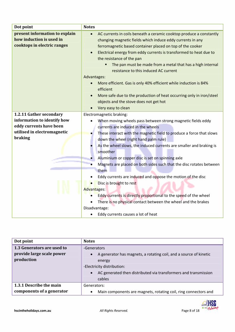
present information to explain how induction is used in cooktops in electric ranges
AC currents in coils beneath a ceramic cooktop produce a constantly changing magnetic fields which induce eddy currents in any ferromagnetic based container placed on top of the cooker
Electrical energy from eddy currents is transformed to heat due to the resistance of the pan The pan must be made from a metal that has a high internal
resistance to this induced AC current Advantages:
More efficient. Gas is only 40% efficient while induction is 84% efficient
More safe due to the production of heat occurring only in iron/steel objects and the stove does not get hot
Very easy to clean
1.2.11 Gather secondary information to identify how eddy currents have been utilised in electromagnetic braking
Electromagnetic braking:
When moving wheels pass between strong magnetic fields eddy currents are induced in the wheels
These interact with the magnetic field to produce a force that slows down the wheel (right hand palm rule)
As the wheel slows, the induced currents are smaller and braking is smoother
Aluminium or copper disc is set on spinning axle
Magnets are placed on both sides such that the disc rotates between them
Eddy currents are induced and oppose the motion of the disc
Disc is brought to rest Advantages:
Eddy currents is directly proportional to the speed of the wheel
There is no physical contact between the wheel and the brakes Disadvantage:
Eddy currents causes a lot of heat
Dot point Notes
1.3 Generators are used to provide large scale power production
-Generators
A generator has magnets, a rotating coil, and a source of kinetic energy
-Electricity distribution:
AC generated then distributed via transformers and transmission cables
1.3.1 Describe the main components of a generator
Generators:
Main components are magnets, rotating coil, ring connectors and

hscintheholidays.com.au All Rights Reserved. Page 9 of 18
Dot point Notes
brushes
Similar structure to motors, except generators convert kinetic energy to electrical energy
In AC generators, slip-rings are used. In DC generators, split-ring commutators are used to reverse the current every half-cycle.
Brushes provide the generated electricity with an outlet to feed the current to the circuit
1.3.2 Compare the structure and function of a generator to an electric motor
There are hardly any structural differences between a generator and a motor
Generators convert kinetic energy into electrical energy while motors do the opposite
1.3.3 Describe the difference between AC and DC generators
Generators:
Armature: rotates to produce electrical energy
Magnets: provides field to induce current in rotating coil
Coil: movement of coil in magnetic field induces current
Brushes: provides the electrical connections for output current to external circuit
Commutators:
AC- ensures current changes direction every half rotation
DC- changes direction of output current every half rotation so it is in a constant direction
1.3.4 Discuss the energy losses that occur as energy is fed through transmission lines from the generator to the consumer
Resistive energy losses:
Heat is generated in transmission lines because of the resistance of the wires
Power lost in transmission lines
Because resistance is fairly constant, power loss is most affected by the size of the current
Energy losses kept to a minimum by transmitting the electricity at the highest practicable voltage, with the lowest practicable current
Energy losses are also minimised through careful choice of materials and design of conductors. Copper or aluminium is used because of its low resistivity.
Aluminium is mostly used because it is lighter than copper (therefore the transmission lines can have a large cross-sectional area without the need for expensive structural supports) and because it is less susceptible to corrosion
Energy losses are minimised by making the transmission voltage very high.
Induction energy losses:
Energy is lost through the induction of eddy currents in the iron core of transformers
The circulation of eddy currents in the transformer core generators

hscintheholidays.com.au All Rights Reserved. Page 10 of 18
Dot point Notes
heat because of the resistance of the iron. Heat represents an energy loss from the electrical system
Transformers cores are usually made of laminated iron. This limits eddy currents to the thickness of one lamination and reduces the heat loss
Induction of eddy currents in metal parts of transmission towers is kept to a minimum by the distance at which the wires are held away from the tower by the insulators
1.3.5 Assess the effects of the development of AC generators on society and the environment
AC generators and society:
Provide electricity to homes resulted in the production of household electrical appliances which increase the standard of living which allowed for more leisure time
The affordability of electricity has promoted the development of a wide range of machines, processes and appliances that depends on electricity. Many tasks that were once performed by hand are now
accomplished with a purpose-built electrical appliance and most domestic and industrial work requires less labour.
However, this has led to a reduction in the demand for unskilled labour and an increase in long-term unemployment
Decentralisation of big cities as AC current can be transmitted over long distances and are cheaper to build and maintain compared to DC
The ready availability of electricity has led to increasing dependency on electricity Any disruption to supply compromises safety and causes
widespread inconvenience and loss of production AC generators and the environment:
Increase in pollution due to the burning of fossil fuels in power stations.
Power transmission lines criss-cross the country with a marked visual impact on the environment, often cutting through environmentally sensitive areas
Alternative power sources can also harm the environment e.g. nuclear power generation has caused various harmful by-products and radiation hazards
AC power generating plants can be located well away from urban areas, shifting pollution away from homes and workplaces, thus improving the environment of cities
1.3.7 Gather secondary information to discuss advantages/disadvantages of AC and DC generators and relate
AC: Advantages:
Easy to transform
Can be transmitted at high voltage, low current and transformed to

hscintheholidays.com.au All Rights Reserved. Page 11 of 18
Dot point Notes
these to their use low voltage, higher current
Energy losses in transmission can be minimised by high voltage transmission
Motors and generators have fewer moving parts so they are more reliable and easier to maintain
Three phase motors powerful for industrial use Disadvantages:
Back emf due to eddy currents lowers power
Emitted electromagnetic radiation interferes with other electronic equipment
Requires thicker insulation to minimise interference from other cables
Is more dangerous because of its 50Hz frequency which can cause heart fibrillation if touched
DC: Advantages:
Does not need as much insulation as it has no electromagnetic radiation output
No back emf
No high frequency radiation to cause interference in other equipment of signals
Transmission has no energy loss due to induction Disadvantages:
Cannot be transformed
More difficult to supply to houses by lines distribution
Equipment not as reliable due to sparking and wear across split ring commutator
1.3.8 Analyse secondary information on the competition between Westinghouse and Edison to supply electricity to cities
Edison (DC): Pros:
Had initial advantage that the technology for generating DC was well established and DC worked well over short distances
Does not cause losses through electromagnetic radiation or induction
Safer to use Cons:
DC could only be generated and distributed at the voltages at which it was used by consumers Huge and expensive energy losses over distances of more
than one or two kilometres
To supply a large city required many power stations throughout the city and an unattractive abundance of wires to carry the required current
Edison had a vested interest in DC as he owned hundreds of DC power stations and all of his many electrical inventions to that time

hscintheholidays.com.au All Rights Reserved. Page 12 of 18
Dot point Notes
ran on DC Attempted to prove that AC was very dangerous by
electrocuting animals on stage and convincing authorities to use AC for the first electric chair. He resorted to legal tactics in an attempt to have AC banned and to prevent its use with his inventions
Westinghouse (AC):
Through the use of transformers the voltage could be stepped up or down as required (could be generated at low voltages and stepped up to higher voltages for transmission over large distance with small energy losses) Needs fewer power stations because of the transformer
Power stations could be fewer and further apart and conductors could be lighter
Received boost in popularity with Tesla’s invention of the induction motor
1.3.9 Gather and analyse information to identify how transmission lines are:
Insulated from supporting structures
Protected from lightning strikes
Insulated from supporting structures:
To prevent sparks jumping from transmission lines to the metal support towers, large insulators separate them from each other
Suspension insulators are used for all high voltage power lines operating at voltages above 33kV. Individual sections of the insulators are disk shaped
Insulators are constructed either of ceramic segments joined together with metal links or of rubber discs with a fibre glass core Reduces the possibility of charge leaking through the
insulators themselves. The metal links in ceramic insulators are isolated from each other, and the fibreglass is a non-conductor, so there is no continuity of conduction
The disk shape of the insulator sections increases the distance that a current has to pass over the surface of the insulator. Less chance that dirt and grime will collect on the undersides
of the sections, and these are also less likely to get wet Ensures a long pathway for any spark discharge across the
insulator Protection from lightning strikes:
Many power towers have a cable running between the known as the continuous earth line (or shield conductors)
Cable normally carriers no current. Acts as a continuous lightning conductor. If struck by lightning, electricity of the lightning will be conducted to the Earth
Insulation chains: prevents the hit from being transmitted into the current-carrying lines Can be up to around 2 m in length: generally, the higher the

hscintheholidays.com.au All Rights Reserved. Page 13 of 18
Dot point Notes
voltage, the longer the chain.
Metal tower: will conduct the lightning strike to earth Towers are well earthed, with a large surface area of metal
buried in the ground, enabling the charge from any lightning strike to dissipate harmlessly in the earth
Distance between towers: large enough so that if the power lines are struck, it will dissipate before reaching the next tower
Uppermost wires are called shield conductors, as they are designed to reduce the chance of a lightning strike to the transmission wires connected directly to the transmission towers and ensure
that current is conducted safely to earth
Dot Point Notes
1.4 Transformers allow generated voltage to be either increased or decreased before it is used
-Transformers – theory:
Increase or decrease AC voltages
-Conservation of energy:
If 100% efficient, then
-Types of transformers:
Step-up and step-down
1.4.1 Describe the purpose of transformers in electrical circuits
Transformers in electrical circuits:
To increase transmission voltage from power stations to reduce energy loss by heating effects
To change the voltage supply to an appliance either up or down
It is common for the step-up or step-down transformer to be built into the appliance as part of its power supply. Many appliances contain both a step-up and a step-down transformer to supply voltages required by different components. Many step-down transformers are multi-tapped transformers capable of supplying a range of different secondary voltages from the same primary input voltage.
1.4.2 Compare step-up and step-down transformers
Step-up and step-down transformers:
Step-up transformers are used to increase the voltage. There is a smaller number of turns in the primary coil and larger number in secondary coil
Step-down transformers are used to decrease the voltage. They have a bigger amount of turns in the primary coil compared to secondary coil

hscintheholidays.com.au All Rights Reserved. Page 14 of 18
Dot Point Notes
1.4.3 Identify the relationship between the ratio of the number of turns in the primary and secondary coils and the ratio of primary to secondary voltage
Relationship between the ratio of number of turns and the voltage:
1.4.4 Explain why voltage transformations are related to conservation of energy
Voltage transformations and conservation of energy:
A consequence of the law of conservation of energy is that output power cannot exceed input power
In reality, due to inefficiencies energy output will be inevitably be less than energy input
Ideal efficient transformers
1.4.5 Explain the role of transformers in electricity sub stations
Transformers in electricity sub stations:
Electricity from power stations is transmitted through the national grid at high voltages. The high voltages are necessary to minimise energy loss due to resistance in the conducting transmission wires as the energy is carried over large distances
Sub-stations use transformers to progressively reduce the voltage as it comes closer to the consumer. At each stage, the output voltage is chosen to match the power demand and the distances over which supply is needed, usually 240V to households from original 500kV
1.4.6 Discuss why some electrical appliances in the home that are connected to the mains domestic power supply use a transformer
Electrical appliances: Electricity supplied to homes is typically 240 V AC. Many domestic
appliances are designed to run most efficiently at this voltage. Such appliances are connected directly to the mains supply without the need for a transformer.
Some appliances contain components that require a transformer because they operate best at lower voltages than the mains supply. In a microwave oven, for example, large, energy consuming parts such as the turntable motor and the microwave transducer may be connected directly to the mains, while the control and display panel is supplied with low voltages from a step-down transformer in a built-in power supply unit.
Many small portable appliances (CD players and mobile telephones), have been designed to run on batteries. Require low DC voltages When the whole appliance is designed to run at the same low
voltage, a step-down transformer-rectifier may be built into the plug of the power supply lead that connects to the mains supply
Alternatively, a normal power lead connects the mains to a built-in power supply unit that contains a step-down transformer and a rectifier.

hscintheholidays.com.au All Rights Reserved. Page 15 of 18
Dot Point Notes
Appliances such as television receivers and computer monitors contain cathode ray tubes that require voltages well above the mains supply, up to around 25 kV, to accelerate electrons toward the screen.
These use a built-in step-up transformer to provide the necessary voltage. The power supply unit may contain both a step-up and a step-down transformer.
1.4.7 Discuss the impact of the development of transformers on society
Transformers and society:
Lifestyles have changed through the use of power tools at home, saving money on others doing maintenance work, or labour-saving devices (e.g. frypans, ovens, hotplates, vacuum cleaners) all which would not be available without the transmission and transformation of AC current to the correct voltages
Leisure activities centred around the use of electricity and has added to the quality of life
The development of transformers made it possible to transmit electrical energy efficiently over great distances. This has had a range of impacts on society.
Even very remote communities now have access to grid-supplied high-voltage electricity which is stepped down locally by transformers. This has raised living standards in rural communities through provision of, for instance, electric lighting, refrigeration and air conditioning, and increased the scope of rural industries.
Large cities have been allowed to spread, because electricity is readily available as an energy source, thanks to transformers. This has led to social dislocation in urban “deserts”, as people have moved further from family and friends and workplaces.
Industry is no longer clustered around power stations or other sources of energy. Power stations can be in remote locations and high-voltage electrical energy can be distributed almost anywhere, to be stepped down near the point of use. This has allowed industries to be decentralised and has facilitated the development of industrial areas away from residential areas. This has relocated pollution away from homes, but it means that many people now spend significant time travelling between home and work.
With the development of the transformer, people have changed the way they live, as electricity to every home has become an affordable necessity rather than a luxury.
1.4.10 Gather, analyse and use available evidence to discuss how difficulties of heating caused by eddy currents in transformers may be overcome
Solutions to heat caused by eddy currents:
Laminating the soft iron core
Providing sink blades to dissipate heat- heat dissipation to the environment can occur more quickly over a larger surface area
Putting air vents in casing- allows air to remove heat by convection

hscintheholidays.com.au All Rights Reserved. Page 16 of 18
Dot Point Notes
currents
Painting casing dark colour- so that the heat produced internally is efficiently radiated to the environment
Filling transformer with circulating coolant- transports the heat produced in the core to the outside where the heat can dissipate into the environment
Putting fans and sprinklers on thermostatic switches- assists in air circulation to remove excess heat faster. They are controlled by thermostatic switches which turn the fans on at specific temperature, usually around 50°
1.4.11 Gather and analyse secondary information to discuss the need for transformers in the transfer of electrical energy from a power station to its point of use
Need for transformers in electrical transmission from source to point of use:
Used at power stations to change voltage of generated electricity (about 10,000V) to higher values (350,000 to 500,000V) for transmission over long distances to energy distribution centres in towns and cities
Allows energy to be distributed with minimum loss of power due to heating effects of current in transmission wires
Used at the distribution centres and other locations in cities as well as in portable devices in homes to change the supply voltage to the value needed by various appliances and machines
Without transformers, if different voltages were needed these would require separate power stations and separate distribution systems, which is expensive, unsightly and unreliable
Energy transformed in generators in power stations (22kV). Step-up transformers to increase voltage and lower current for efficient movement of electricity (330kV). Regional sub-stations, step-down transformers reduce voltage (110kV). Local sub-stations reduce to 33kV or 11kV. Pole-mounted transformers step this down again for supply to houses and factories at 415/240V.

hscintheholidays.com.au All Rights Reserved. Page 17 of 18
Dot Point Notes
1.5 Motors are used in industries and the home usually to convert electrical energy into more useful forms of energy
-AC motors – structure:
An AC motor has a rotor and a stator, and spins at 50Hz -AC induction motors:
Sealed prior gets pushed around by rotating field of the stator
Cheap and reliable, hence common
1.5.1 Describe the main features of an AC electric motor
AC motors have two main parts: Two types of AC electric motors: synchronous and induction Synchronous motor:
Stators: permanent magnets or electromagnetic
Rotor: coil
An alternating voltage is applied to the rotor coil via slip rings. The speed of the coil is synchronised to the frequency of the applied voltage
The current direction is reversed by alternating the current used rather than by a split ring commutator
Rarely used for heavy loads because they can slow down, lose their synchronisation, become inefficient and sometimes fail altogether
Induction motor: The stator consists of a series of wire coils wound on soft iron cores
that surround the rotor. These are connected to the external power supply in such a way that they produce a magnetic field whose polarity rotates at constant speed in one direction. This is achieved in a three-phase induction motor by connecting consecutive coils in opposing pairs to the three phases of the power supply. Many single-phase induction motors use capacitors to simulate the three-phase effect.
The rotor consists of coils wound on a laminated iron armature mounted on an axle. The rotor coils are not connected to the external power supply, and an induction motor has neither commutator nor brushes.
An induction motor is named so because eddy currents are induced in the rotor coils by the rotating magnetic field of the stator. The eddy currents produce magnetic fields which interact with the rotating field of the stator to exert a torque on the rotor in the direction of rotation of the stator field.
The rotor coils are often simplified to single copper bars capable of carrying a large current, imbedded in the surface of the armature. The bars are connected at the ends by a ring or disc of copper which allows current to flow in a loop between opposite bars i.e. squirrel cage structure
An induction motor has a fixed maximum speed. The magnetic field

hscintheholidays.com.au All Rights Reserved. Page 18 of 18
of the stator rotates at the frequency of the AC supply. In Australia, induction motors spin at about 3000 revolutions per minute (50 Hz x 60 seconds) without a load, but the speed of the rotor slips behind that of the field as a load is applied.
1.5.2 Gather, process and analyse information to identify some of the energy transfers and transformations involving the conversion of electrical energy into more useful forms in the home and industry
Identify some energy transformations:
In the home In industry
Electrical energy is transformed into radiant energy as:
light in light globes
heat in toaster and kettle
microwaves in microwave oven
radio waves in cordless phone
Electrical energy is transformed into radiant energy as:
X-rays in medical imaging
light in laser circuit printing
heat in induction ovens
microwaves in wood curing
radio waves in communication
Electrical energy is transformed into mechanical energy as:
rotation in food blender motor
vibration in television speaker
Electrical energy is transformed into mechanical energy as:
rotation in industrial motors
vibration in television speaker
kinetic energy and gravitational potential energy in fun park rides
Electrical energy is transformed into chemical energy in recharging rechargeable batteries
Electrical energy is transformed into chemical energy in the electroplating process