toolbox tuesdays march 10, 2009 -...
TRANSCRIPT
1
Toolbox Tuesdays March 10, 2009
Training Materials:
Visualization: Introduction to Google Earth & SketchUp
2
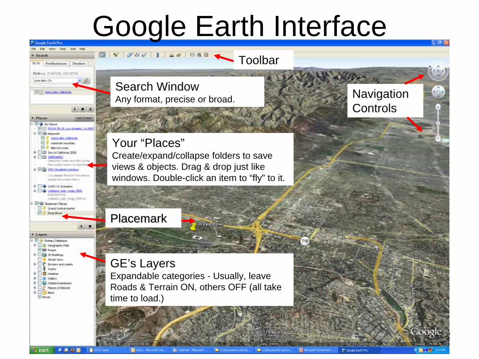
Google Earth InterfaceToolbar
Navigation Controls
PlacemarkPlacemark
Search Window Any format, precise or broad.
Your “Places” Create/expand/collapse folders to save views & objects. Drag & drop just like windows. Double-click an item to “fly” to it.
GE’s Layers Expandable categories - Usually, leave Roads & Terrain ON, others OFF (all take time to load.)
3
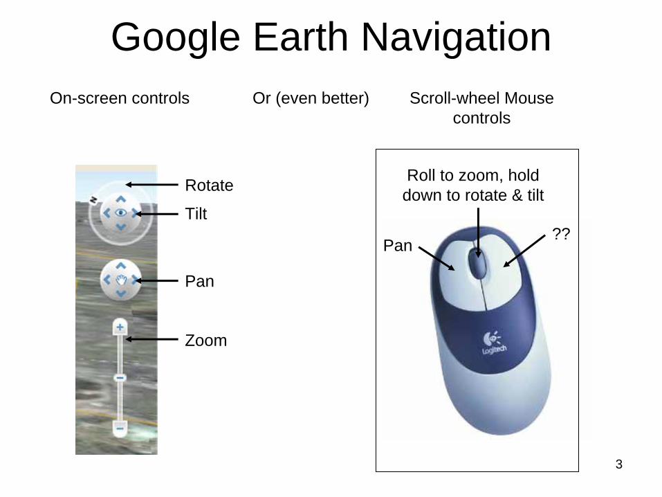
Google Earth NavigationOn-screen controls Or (even better) Scroll-wheel Mouse
controls
Rotate
Tilt
Pan
Zoom
Pan??
Roll to zoom, hold down to rotate & tilt
4
Placemarks
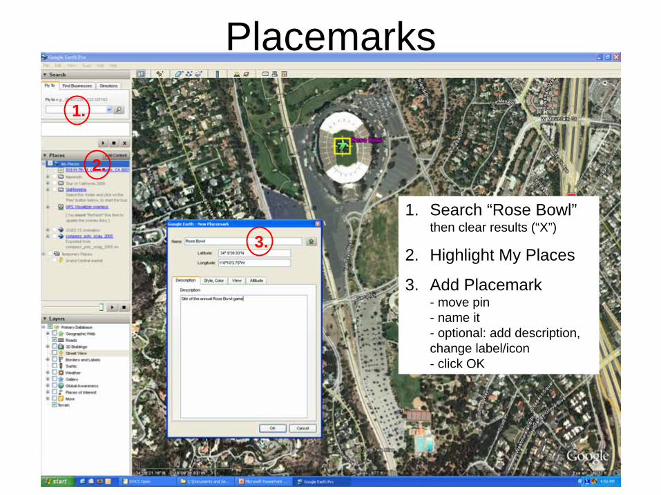
1. Search “Rose Bowl” then clear results (“X”)
2. Highlight My Places
3. Add Placemark - move pin - name it - optional: add description, change label/icon - click OK
1.
2.
3.
5
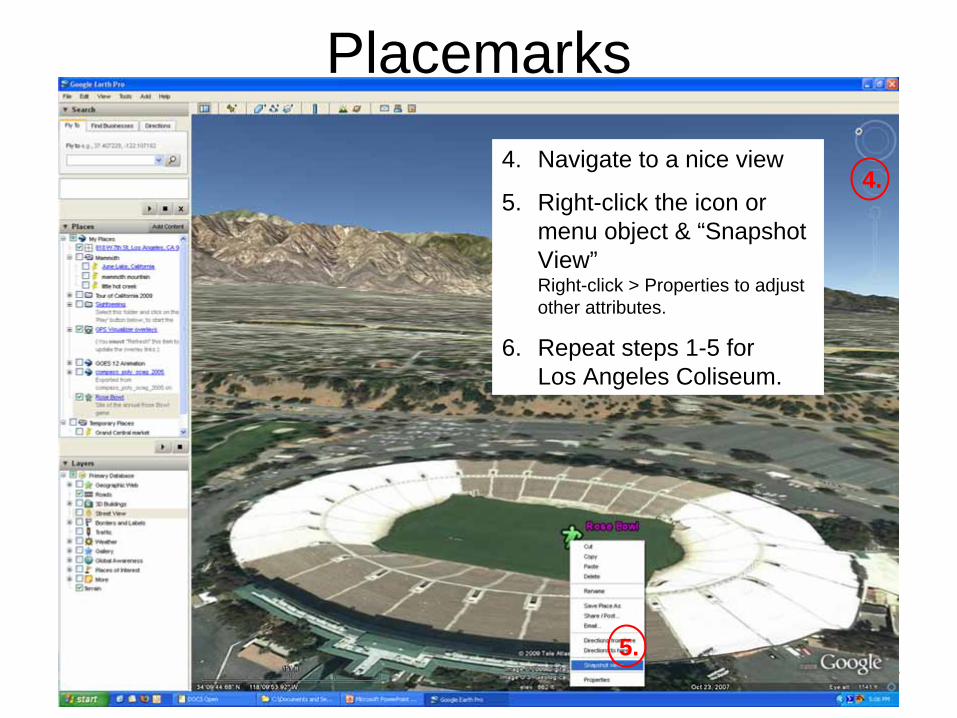
Placemarks4. Navigate to a nice view
5. Right-click the icon or menu object & “Snapshot View” Right-click > Properties to adjust other attributes.
6. Repeat steps 1-5 for Los Angeles Coliseum.
4.
5.
6
Placemarks
11.
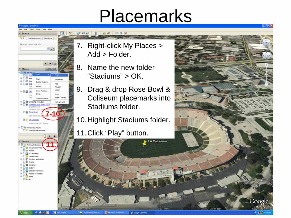
7. Right-click My Places > Add > Folder.
8. Name the new folder “Stadiums” > OK.
9. Drag & drop Rose Bowl & Coliseum placemarks into Stadiums folder.
10.Highlight Stadiums folder.
11.Click “Play” button.
7-10.
7
Ruler Tool
1.3.
4.
2.
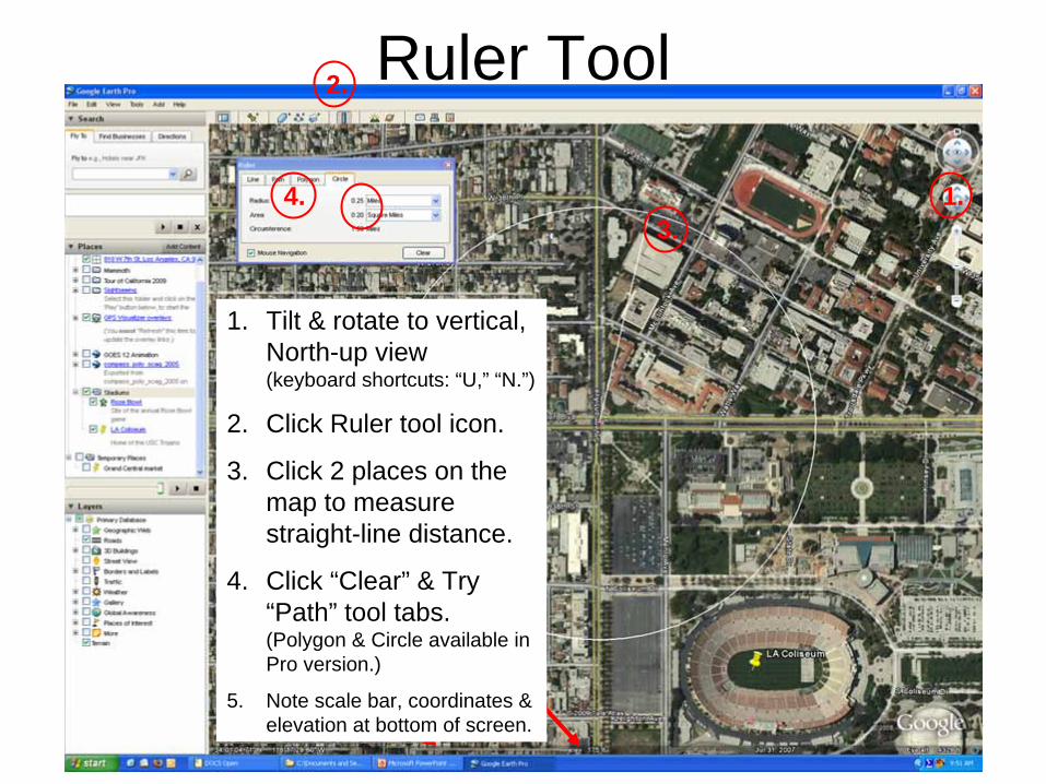
1. Tilt & rotate to vertical, North-up view (keyboard shortcuts: “U,” “N.”)
2. Click Ruler tool icon.
3. Click 2 places on the map to measure straight-line distance.
4. Click “Clear” & Try “Path” tool tabs. (Polygon & Circle available in Pro version.)
5. Note scale bar, coordinates & elevation at bottom of screen.
8
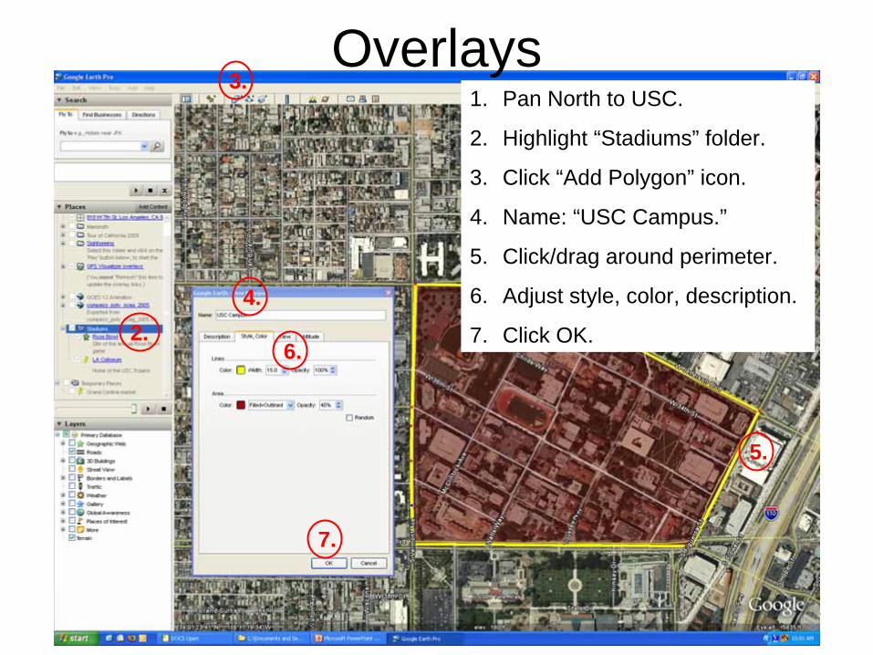
Overlays1. Pan North to USC.
2. Highlight “Stadiums” folder.
3. Click “Add Polygon” icon.
4. Name: “USC Campus.”
5. Click/drag around perimeter.
6. Adjust style, color, description.
7. Click OK.
3.
2.4.
5.
6.
7.
9
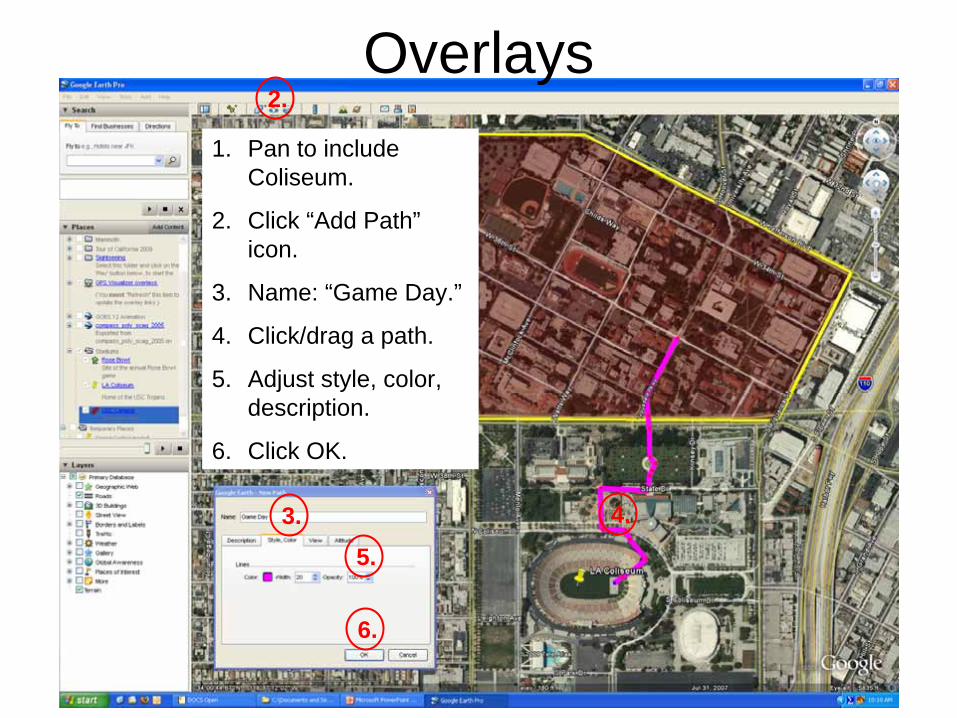
Overlays1. Pan to include
Coliseum.
2. Click “Add Path” icon.
3. Name: “Game Day.”
4. Click/drag a path.
5. Adjust style, color, description.
6. Click OK.
2.
3. 4.
6.
5.
10
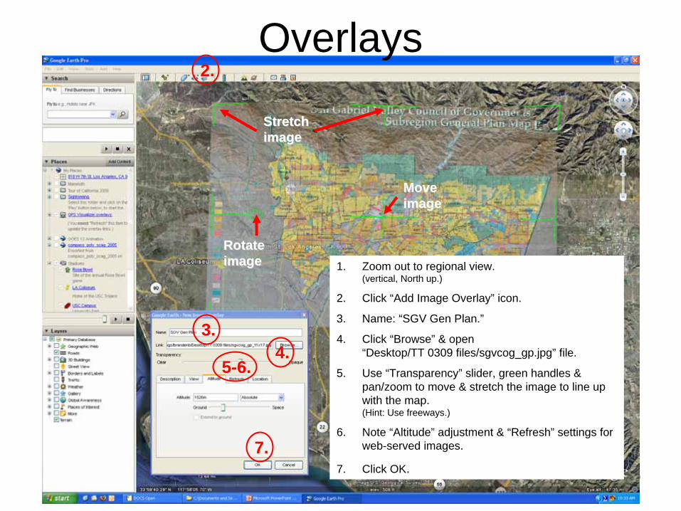
1. Zoom out to regional view. (vertical, North up.)
2. Click “Add Image Overlay” icon.
3. Name: “SGV Gen Plan.”
4. Click “Browse” & open “Desktop/TT 0309 files/sgvcog_gp.jpg” file.
5. Use “Transparency” slider, green handles & pan/zoom to move & stretch the image to line up with the map. (Hint: Use freeways.)
6. Note “Altitude” adjustment & “Refresh” settings for web-served images.
7. Click OK.
Overlays2.
3.4.
Rotate Rotate imageimage
5-6.
Move Move imageimage
Stretch Stretch imageimage
7.
11
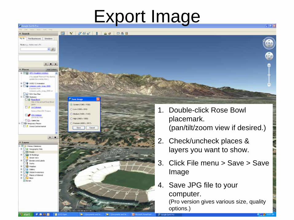
1. Double-click Rose Bowl placemark. (pan/tilt/zoom view if desired.)
2. Check/uncheck places & layers you want to show.
3. Click File menu > Save > Save Image
4. Save JPG file to your computer. (Pro version gives various size, quality options.)
Export Image
12
Create KMZ Files
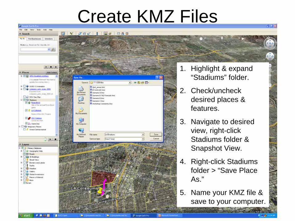
1. Highlight & expand “Stadiums” folder.
2. Check/uncheck desired places & features.
3. Navigate to desired view, right-click Stadiums folder & Snapshot View.
4. Right-click Stadiums folder > “Save Place As.”
5. Name your KMZ file & save to your computer.
13
Share KMZ Files
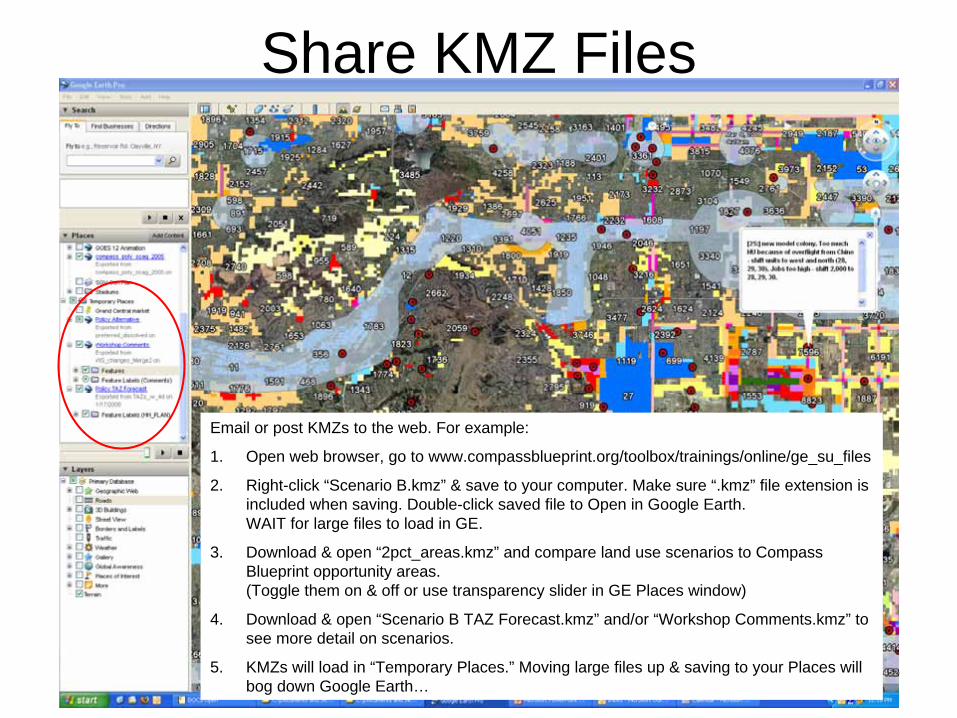
Email or post KMZs to the web. For example:
1. Open web browser, go to www.compassblueprint.org/toolbox/trainings/online/ge_su_files
2. Right-click “Scenario B.kmz” & save to your computer. Make sure “.kmz” file extension is included when saving. Double-click saved file to Open in Google Earth. WAIT for large files to load in GE.
3. Download & open “2pct_areas.kmz” and compare land use scenarios to Compass Blueprint opportunity areas. (Toggle them on & off or use transparency slider in GE Places window)
4. Download & open “Scenario B TAZ Forecast.kmz” and/or “Workshop Comments.kmz” to see more detail on scenarios.
5. KMZs will load in “Temporary Places.” Moving large files up & saving to your Places will bog down Google Earth…
14
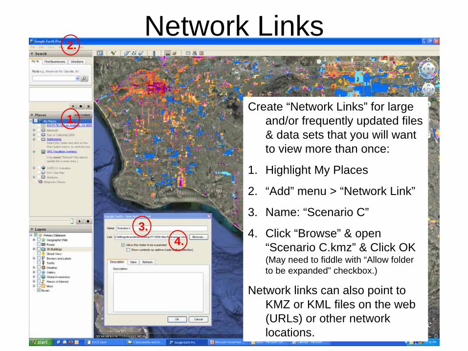
Create “Network Links” for large and/or frequently updated files & data sets that you will want to view more than once:
1. Highlight My Places
2. “Add” menu > “Network Link”
3. Name: “Scenario C”
4. Click “Browse” & open “Scenario C.kmz” & Click OK (May need to fiddle with “Allow folder to be expanded” checkbox.)
Network links can also point to KMZ or KML files on the web (URLs) or other network locations.
Network Links
3.
1.
2.
4.
15
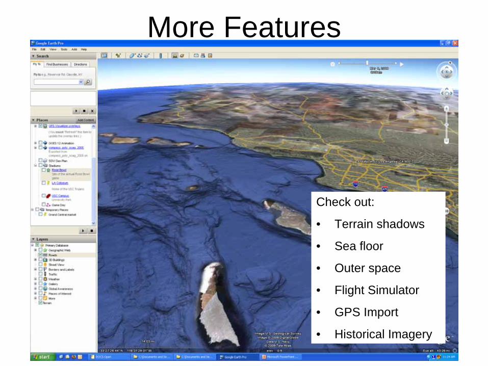
Check out:
• Terrain shadows
• Sea floor
• Outer space
• Flight Simulator
• GPS Import
• Historical Imagery
More Features
16
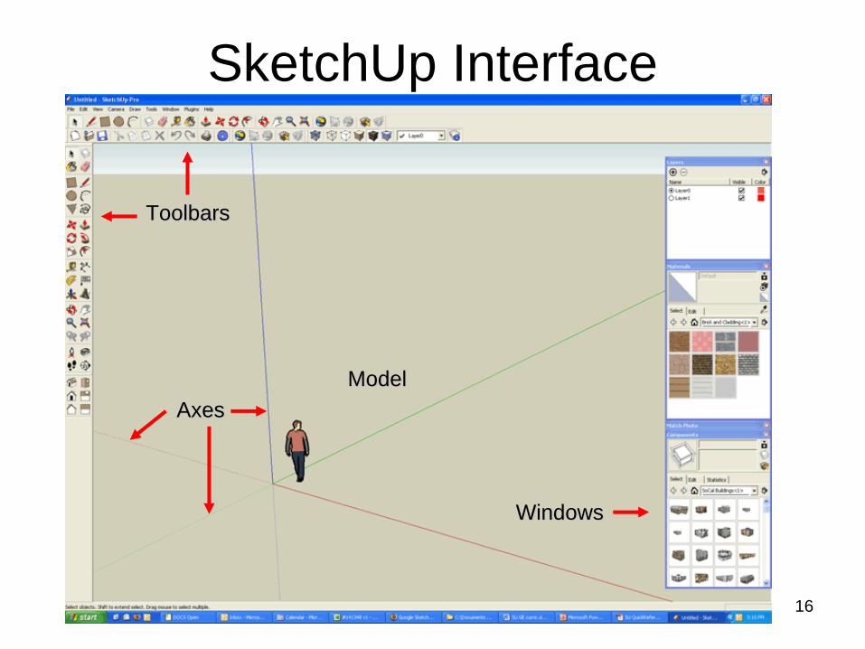
SketchUp Interface
ToolbarsToolbars
WindowsWindows
ModelModelAxesAxes
17
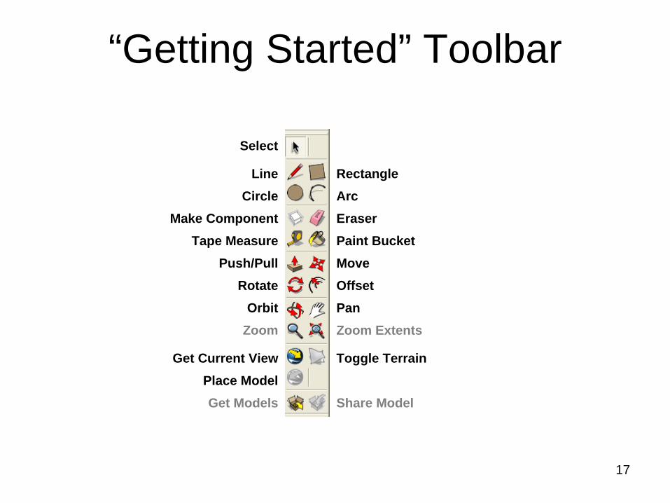
“Getting Started” Toolbar
Make Component
Push/PullTape Measure
RotateOrbit
Zoom
Get Current ViewPlace ModelGet Models
Select
LineCircle
MovePaint Bucket
OffsetPanZoom Extents
Toggle Terrain
Share Model
RectangleArcEraser
18
19
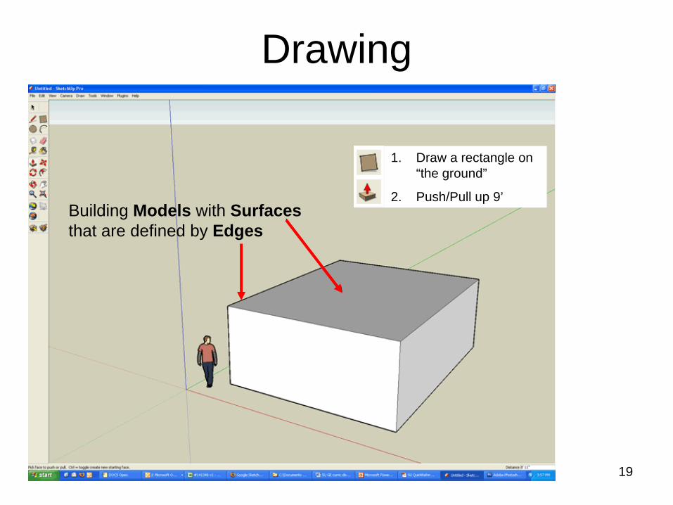
Drawing
Building Models with Surfaces that are defined by Edges
1. Draw a rectangle on “the ground”
2. Push/Pull up 9’
20
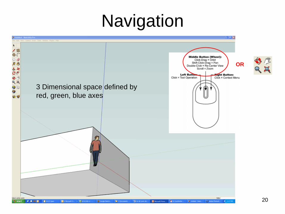
Navigation
3 Dimensional space defined by red, green, blue axes
OR
21
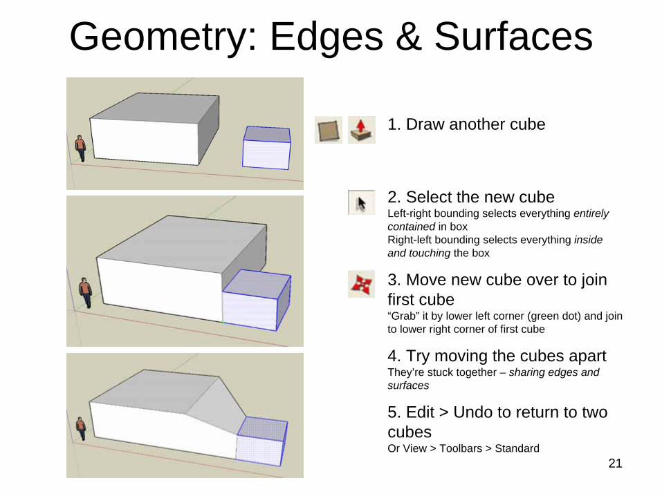
Geometry: Edges & Surfaces
1. Draw another cube
2. Select the new cube Left-right bounding selects everything entirely contained in box Right-left bounding selects everything inside and touching the box
3. Move new cube over to join first cube “Grab” it by lower left corner (green dot) and join to lower right corner of first cube
4. Try moving the cubes apart They’re stuck together – sharing edges and surfaces
5. Edit > Undo to return to two cubes Or View > Toolbars > Standard
22
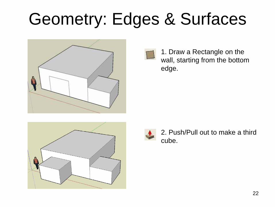
1. Draw a Rectangle on the wall, starting from the bottom edge.
2. Push/Pull out to make a third cube.
Geometry: Edges & Surfaces
23
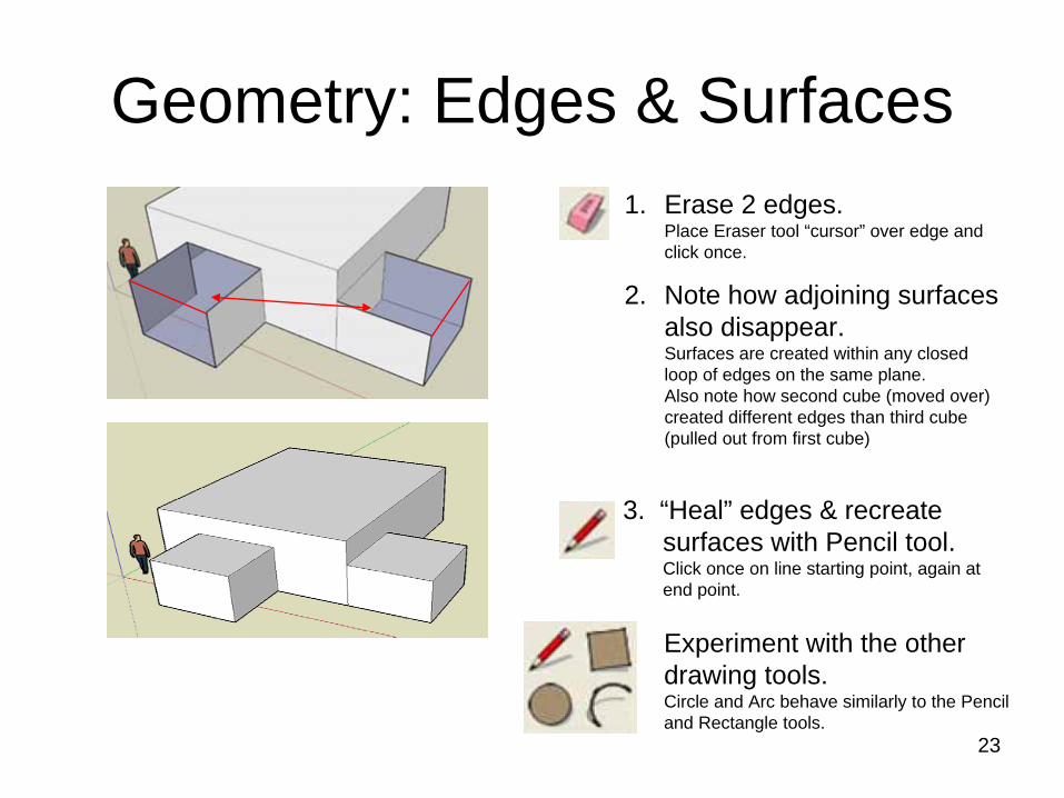
1. Erase 2 edges. Place Eraser tool “cursor” over edge and click once.
2. Note how adjoining surfaces also disappear. Surfaces are created within any closed loop of edges on the same plane. Also note how second cube (moved over) created different edges than third cube (pulled out from first cube)
3. “Heal” edges & recreate surfaces with Pencil tool. Click once on line starting point, again at end point.
Experiment with the other drawing tools. Circle and Arc behave similarly to the Pencil and Rectangle tools.
Geometry: Edges & Surfaces
24
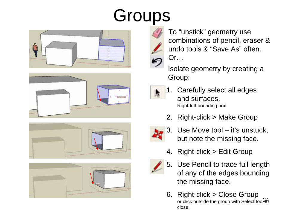
GroupsTo “unstick” geometry use combinations of pencil, eraser & undo tools & “Save As” often. Or…Isolate geometry by creating a Group:
1. Carefully select all edges and surfaces. Right-left bounding box
2. Right-click > Make Group
3. Use Move tool – it’s unstuck, but note the missing face.
4. Right-click > Edit Group
5. Use Pencil to trace full length of any of the edges bounding the missing face.
6. Right-click > Close Group or click outside the group with Select tool to close.
25
Groups vs. Components
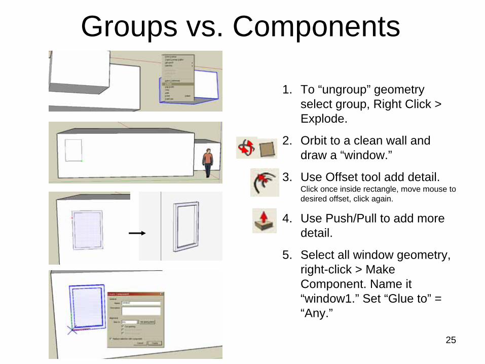
1. To “ungroup” geometry select group, Right Click > Explode.
2. Orbit to a clean wall and draw a “window.”
3. Use Offset tool add detail. Click once inside rectangle, move mouse to desired offset, click again.
4. Use Push/Pull to add more detail.
5. Select all window geometry, right-click > Make Component. Name it “window1.” Set “Glue to” = “Any.”
26
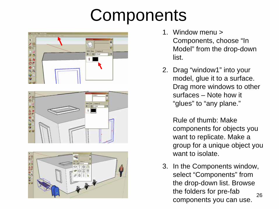
Components1. Window menu >
Components, choose “In Model” from the drop-down list.
2. Drag “window1” into your model, glue it to a surface. Drag more windows to other surfaces – Note how it “glues” to “any plane.”
Rule of thumb: Make components for objects you want to replicate. Make a group for a unique object you want to isolate.
3. In the Components window, select “Components” from the drop-down list. Browse the folders for pre-fab components you can use.
27
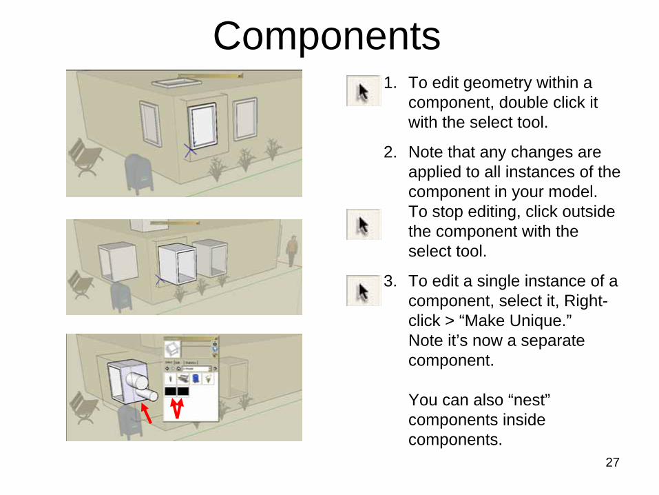
Components1. To edit geometry within a
component, double click it with the select tool.
2. Note that any changes are applied to all instances of the component in your model. To stop editing, click outside the component with the select tool.
3. To edit a single instance of a component, select it, Right- click > “Make Unique.” Note it’s now a separate component.
You can also “nest” components inside components.
28
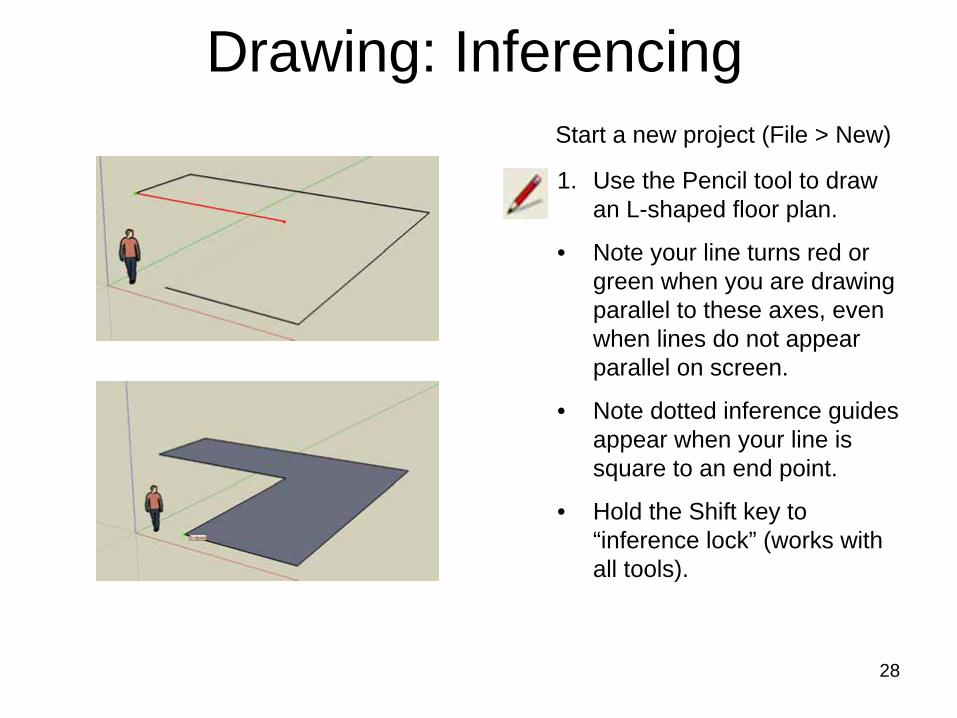
Drawing: Inferencing
1. Use the Pencil tool to draw an L-shaped floor plan.
• Note your line turns red or green when you are drawing parallel to these axes, even when lines do not appear parallel on screen.
• Note dotted inference guides appear when your line is square to an end point.
• Hold the Shift key to “inference lock” (works with all tools).
Start a new project (File > New)
29
Drawing: Inferencing
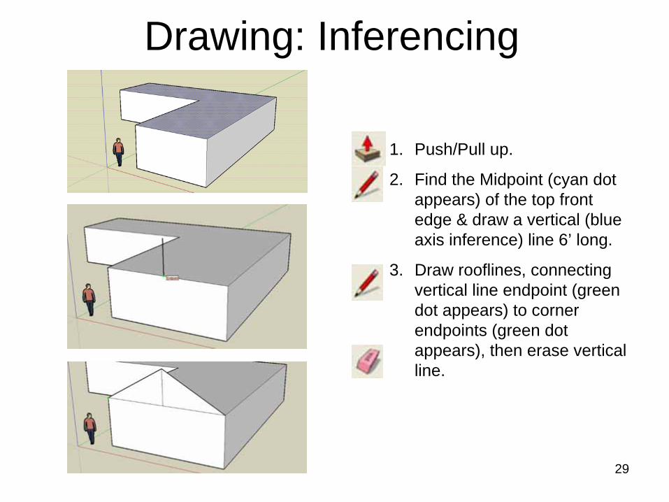
1. Push/Pull up.
2. Find the Midpoint (cyan dot appears) of the top front edge & draw a vertical (blue axis inference) line 6’ long.
3. Draw rooflines, connecting vertical line endpoint (green dot appears) to corner endpoints (green dot appears), then erase vertical line.
30
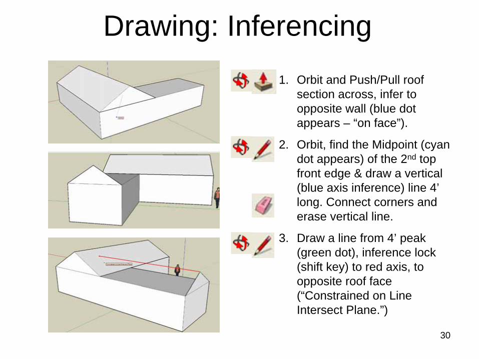
Drawing: Inferencing1. Orbit and Push/Pull roof
section across, infer to opposite wall (blue dot appears – “on face”).
2. Orbit, find the Midpoint (cyan dot appears) of the 2nd top front edge & draw a vertical (blue axis inference) line 4’ long. Connect corners and erase vertical line.
3. Draw a line from 4’ peak (green dot), inference lock (shift key) to red axis, to opposite roof face (“Constrained on Line Intersect Plane.”)
31
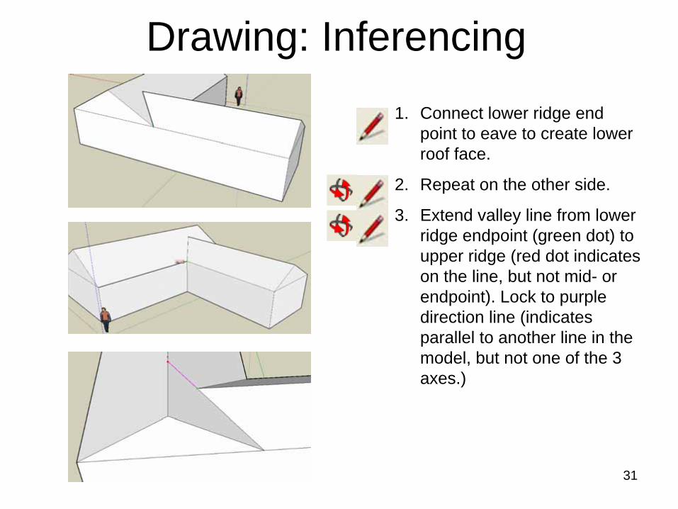
Drawing: Inferencing1. Connect lower ridge end
point to eave to create lower roof face.
2. Repeat on the other side.
3. Extend valley line from lower ridge endpoint (green dot) to upper ridge (red dot indicates on the line, but not mid- or endpoint). Lock to purple direction line (indicates parallel to another line in the model, but not one of the 3 axes.)
32
Drawing: Inferencing
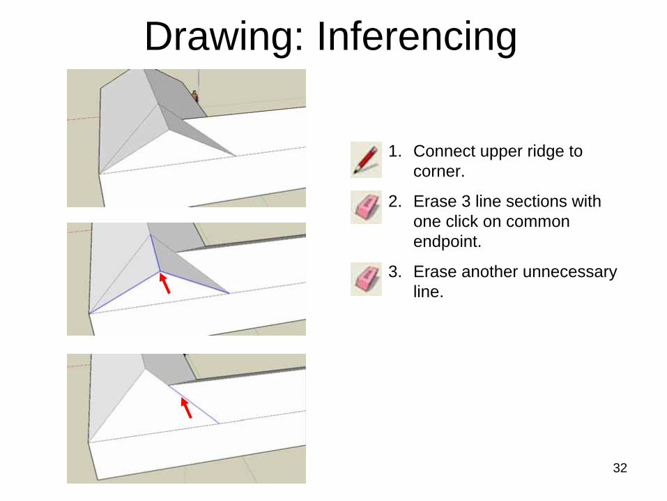
1. Connect upper ridge to corner.
2. Erase 3 line sections with one click on common endpoint.
3. Erase another unnecessary line.
33
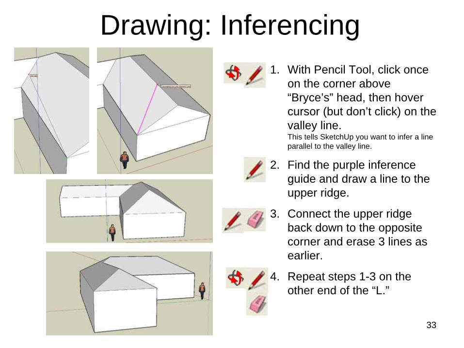
Drawing: Inferencing1. With Pencil Tool, click once
on the corner above “Bryce’s” head, then hover cursor (but don’t click) on the valley line. This tells SketchUp you want to infer a line parallel to the valley line.
2. Find the purple inference guide and draw a line to the upper ridge.
3. Connect the upper ridge back down to the opposite corner and erase 3 lines as earlier.
4. Repeat steps 1-3 on the other end of the “L.”
34
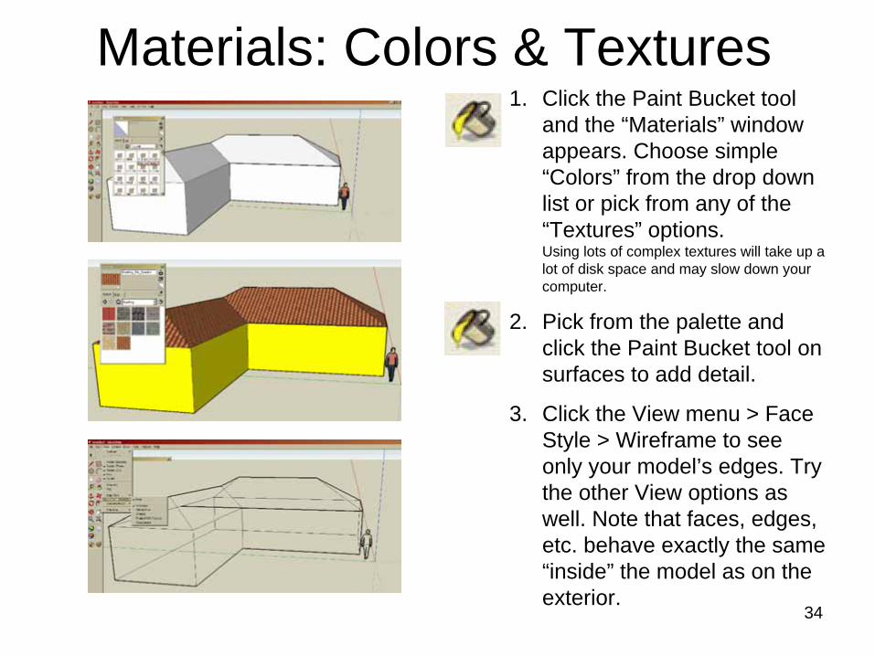
Materials: Colors & Textures1. Click the Paint Bucket tool
and the “Materials” window appears. Choose simple “Colors” from the drop down list or pick from any of the “Textures” options. Using lots of complex textures will take up a lot of disk space and may slow down your computer.
2. Pick from the palette and click the Paint Bucket tool on surfaces to add detail.
3. Click the View menu > Face Style > Wireframe to see only your model’s edges. Try the other View options as well. Note that faces, edges, etc. behave exactly the same “inside” the model as on the exterior.
35
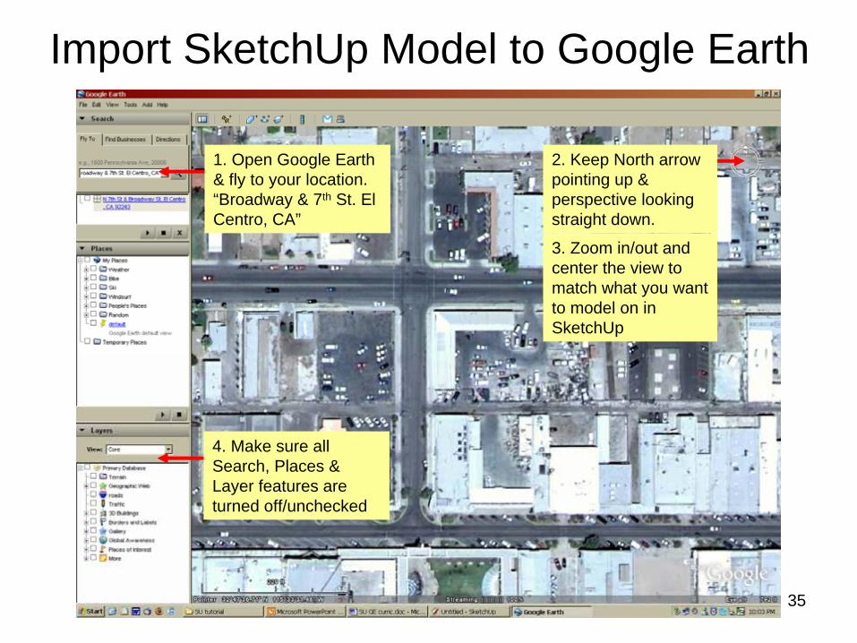
Import SketchUp Model to Google Earth
1. Open Google Earth & fly to your location. “Broadway & 7th St. El Centro, CA”
4. Make sure all Search, Places & Layer features are turned off/unchecked
3. Zoom in/out and center the view to match what you want to model on in SketchUp
2. Keep North arrow pointing up & perspective looking straight down.
36
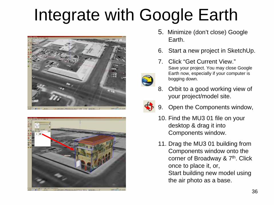
Integrate with Google Earth5. Minimize (don’t close) Google
Earth.
6. Start a new project in SketchUp.
7. Click “Get Current View.” Save your project. You may close Google Earth now, especially if your computer is bogging down.
8. Orbit to a good working view of your project/model site.
9. Open the Components window,
10. Find the MU3 01 file on your desktop & drag it into Components window.
11. Drag the MU3 01 building from Components window onto the corner of Broadway & 7th. Click once to place it, or, Start building new model using the air photo as a base.
37
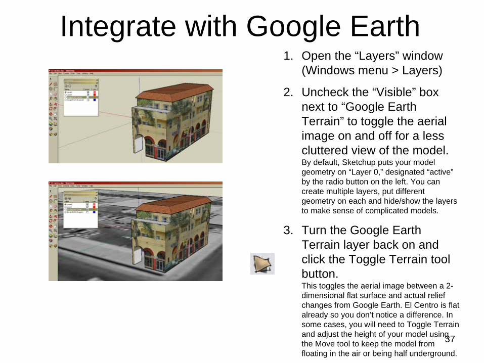
Integrate with Google Earth1. Open the “Layers” window
(Windows menu > Layers)
2. Uncheck the “Visible” box next to “Google Earth Terrain” to toggle the aerial image on and off for a less cluttered view of the model. By default, Sketchup puts your model geometry on “Layer 0,” designated “active” by the radio button on the left. You can create multiple layers, put different geometry on each and hide/show the layers to make sense of complicated models.
3. Turn the Google Earth Terrain layer back on and click the Toggle Terrain tool button. This toggles the aerial image between a 2- dimensional flat surface and actual relief changes from Google Earth. El Centro is flat already so you don’t notice a difference. In some cases, you will need to Toggle Terrain and adjust the height of your model using the Move tool to keep the model from floating in the air or being half underground.
38
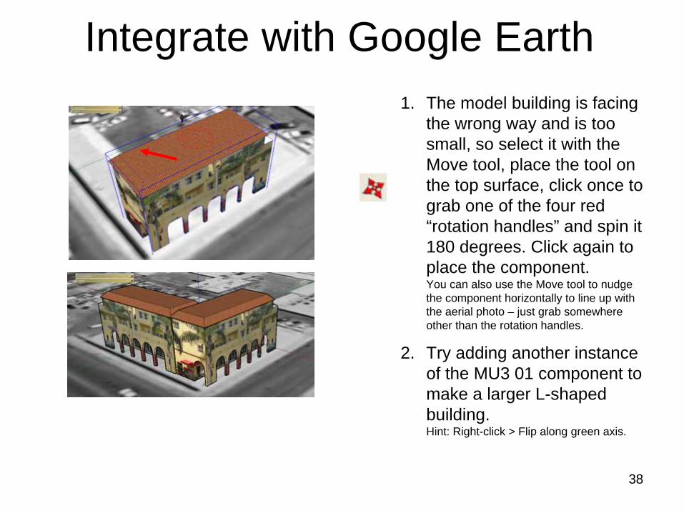
Integrate with Google Earth1. The model building is facing
the wrong way and is too small, so select it with the Move tool, place the tool on the top surface, click once to grab one of the four red “rotation handles” and spin it 180 degrees. Click again to place the component. You can also use the Move tool to nudge the component horizontally to line up with the aerial photo – just grab somewhere other than the rotation handles.
2. Try adding another instance of the MU3 01 component to make a larger L-shaped building. Hint: Right-click > Flip along green axis.
39
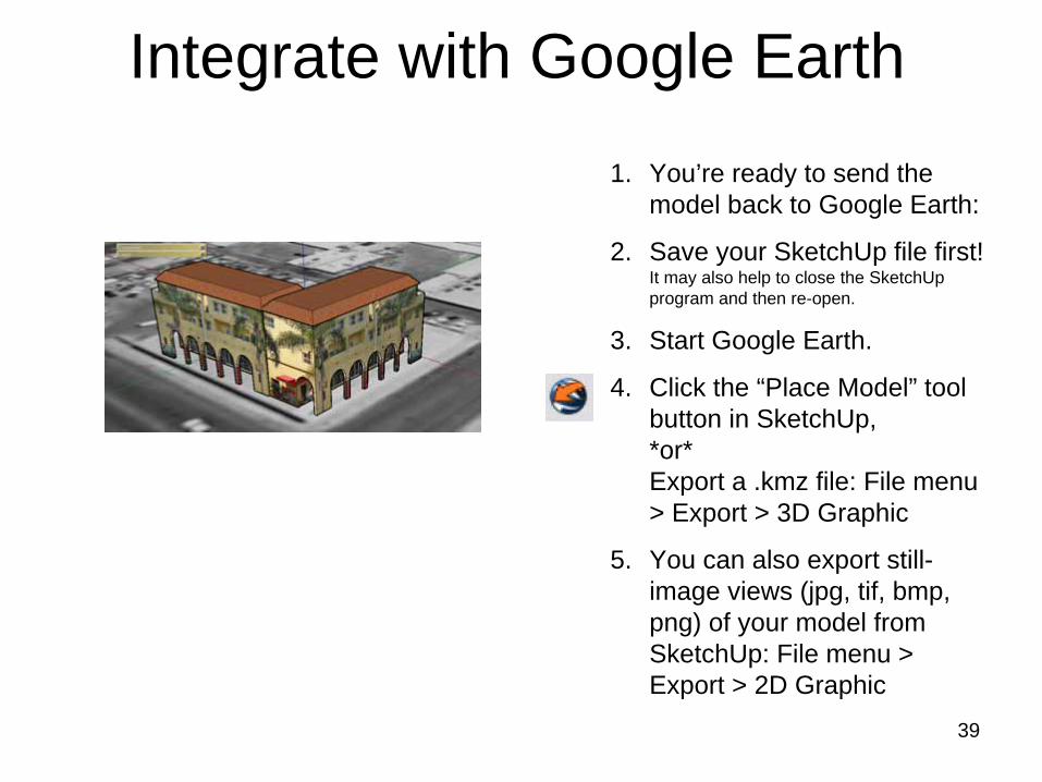
Integrate with Google Earth1. You’re ready to send the
model back to Google Earth:
2. Save your SketchUp file first! It may also help to close the SketchUp program and then re-open.
3. Start Google Earth.
4. Click the “Place Model” tool button in SketchUp, *or* Export a .kmz file: File menu > Export > 3D Graphic
5. You can also export still- image views (jpg, tif, bmp, png) of your model from SketchUp: File menu > Export > 2D Graphic
40
Integrate with Google Earth
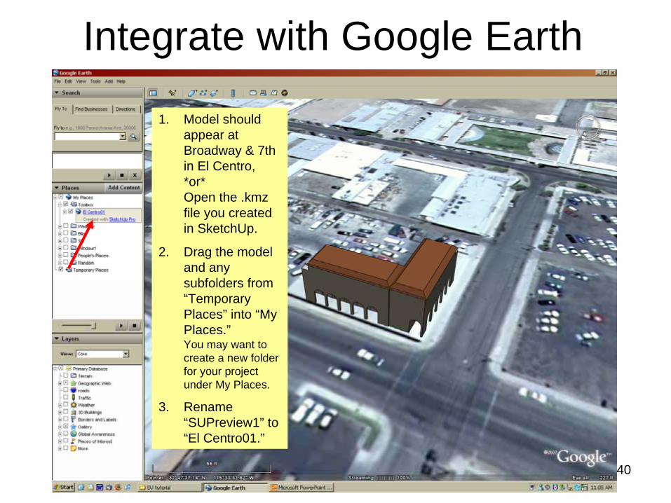
1. Model should appear at Broadway & 7th in El Centro, *or* Open the .kmz file you created in SketchUp.
2. Drag the model and any subfolders from “Temporary Places” into “My Places.” You may want to create a new folder for your project under My Places.
3. Rename “SUPreview1” to “El Centro01.”
41
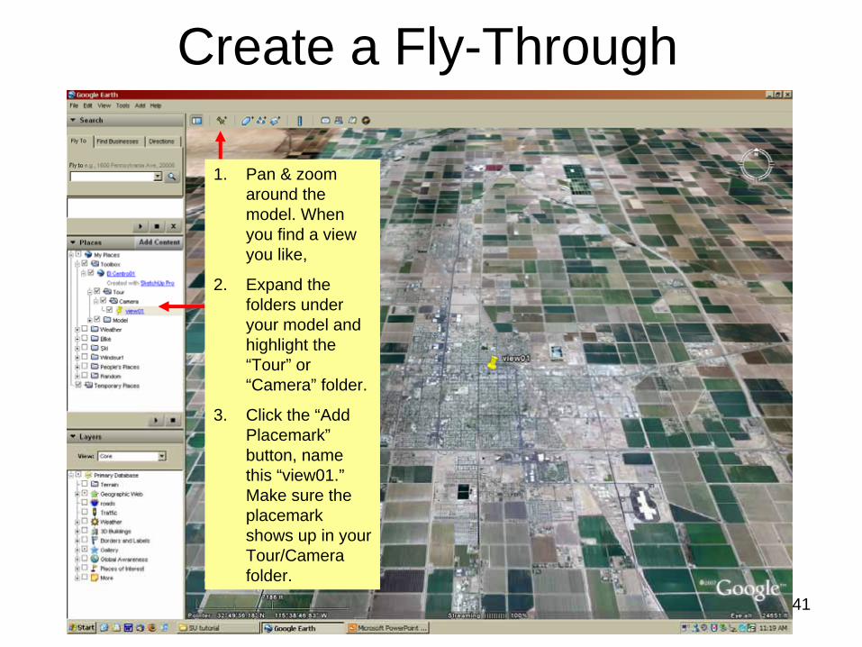
Create a Fly-Through
1. Pan & zoom around the model. When you find a view you like,
2. Expand the folders under your model and highlight the “Tour” or “Camera” folder.
3. Click the “Add Placemark” button, name this “view01.” Make sure the placemark shows up in your Tour/Camera folder.

42
Create a Fly-Through
1. Continue setting up views & creating placemarks in your Tour or Camera folder – “view02, view03,” etc.
2. Drag the view placemarks up & down the list to create the desired fly- through sequence.
43
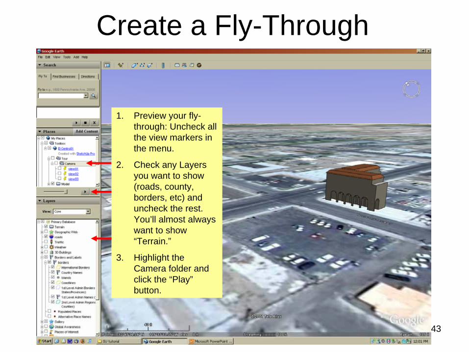
Create a Fly-Through
1. Preview your fly- through: Uncheck all the view markers in the menu.
2. Check any Layers you want to show (roads, county, borders, etc) and uncheck the rest. You’ll almost always want to show “Terrain.”
3. Highlight the Camera folder and click the “Play” button.
44
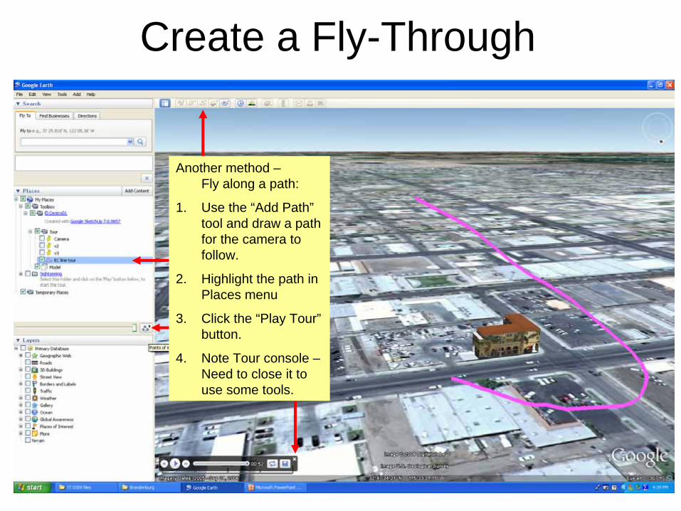
Create a Fly-Through
Another method – Fly along a path:
1. Use the “Add Path” tool and draw a path for the camera to follow.
2. Highlight the path in Places menu
3. Click the “Play Tour” button.
4. Note Tour console – Need to close it to use some tools.
45
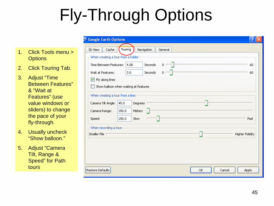
Fly-Through Options
1. Click Tools menu > Options
2. Click Touring Tab.
3. Adjust “Time Between Features” & “Wait at Features” (use value windows or sliders) to change the pace of your fly-through.
4. Usually uncheck “Show balloon.”
5. Adjust “Camera Tilt, Range & Speed” for Path tours
46
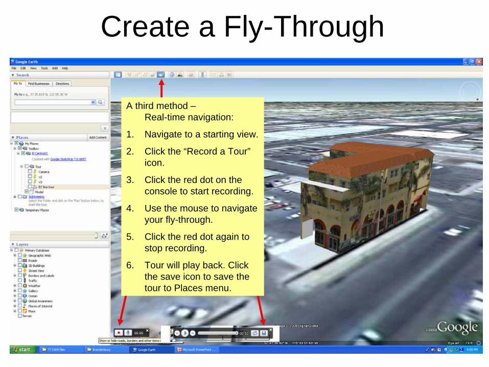
Create a Fly-Through
A third method – Real-time navigation:
1. Navigate to a starting view.
2. Click the “Record a Tour” icon.
3. Click the red dot on the console to start recording.
4. Use the mouse to navigate your fly-through.
5. Click the red dot again to stop recording.
6. Tour will play back. Click the save icon to save the tour to Places menu.
47
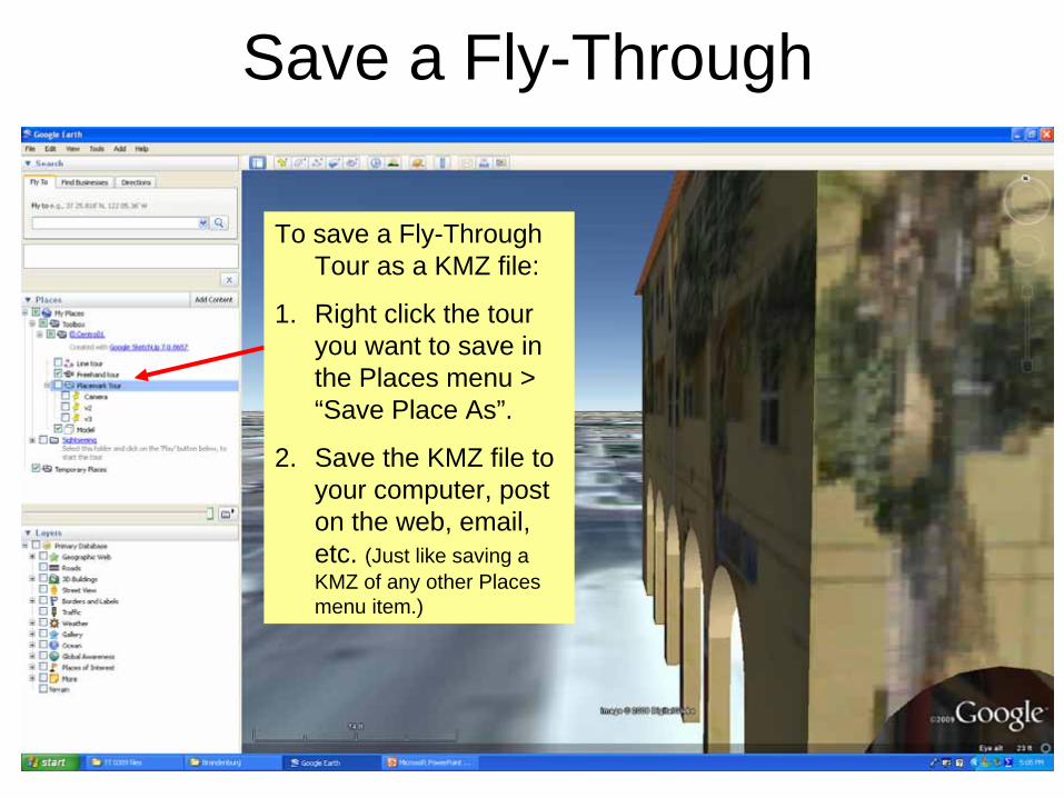
Save a Fly-Through
To save a Fly-Through Tour as a KMZ file:
1. Right click the tour you want to save in the Places menu > “Save Place As”.
2. Save the KMZ file to your computer, post on the web, email, etc. (Just like saving a KMZ of any other Places menu item.)
48
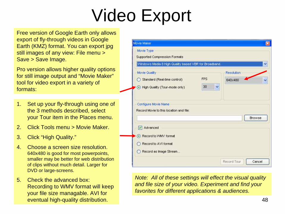
Video Export
1. Set up your fly-through using one of the 3 methods described, select your Tour item in the Places menu.
2. Click Tools menu > Movie Maker.
3. Click “High Quality.”
4. Choose a screen size resolution. 640x480 is good for most powerpoints, smaller may be better for web distribution of clips without much detail. Larger for DVD or large-screens.
5. Check the advanced box: Recording to WMV format will keep your file size managable. AVI for eventual high-quality distribution.
Free version of Google Earth only allows export of fly-through videos in Google Earth (KMZ) format. You can export jpg still images of any view: File menu > Save > Save Image.
Pro version allows higher quality options for still image output and “Movie Maker” tool for video export in a variety of formats:
Note: All of these settings will effect the visual quality and file size of your video. Experiment and find your favorites for different applications & audiences.
49
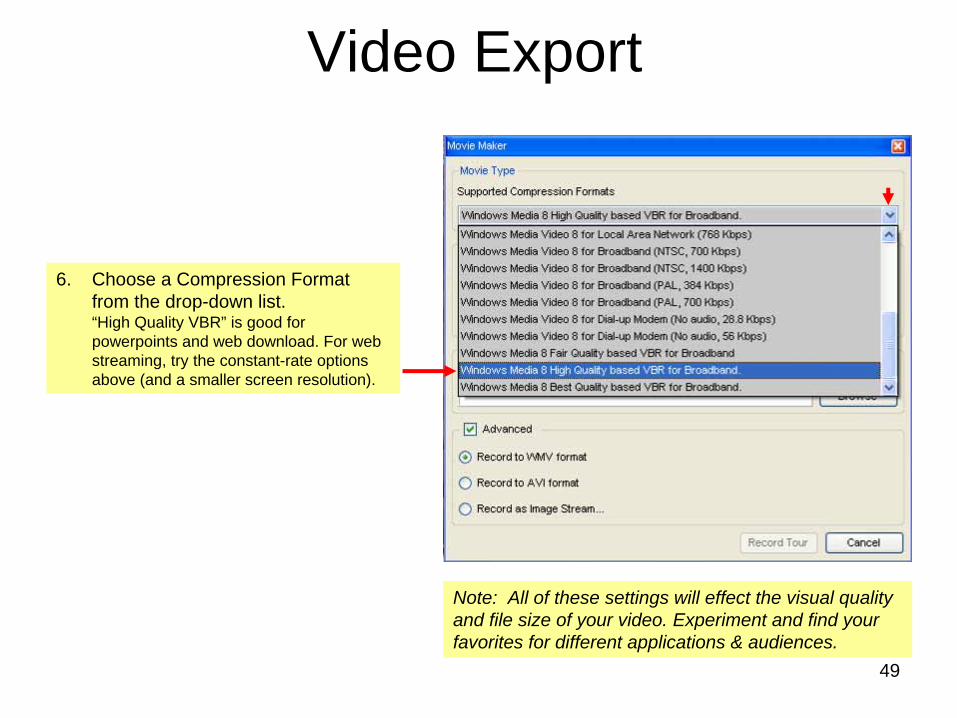
Video Export
6. Choose a Compression Format from the drop-down list. “High Quality VBR” is good for powerpoints and web download. For web streaming, try the constant-rate options above (and a smaller screen resolution).
Note: All of these settings will effect the visual quality and file size of your video. Experiment and find your favorites for different applications & audiences.
50
Video Export
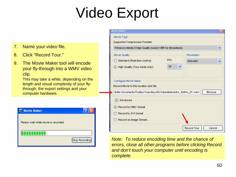
7. Name your video file.
8. Click “Record Tour.”
9. The Movie Maker tool will encode your fly-through into a WMV video clip. This may take a while, depending on the length and visual complexity of your fly- through, the export settings and your computer hardware.
Note: To reduce encoding time and the chance of errors, close all other programs before clicking Record and don’t touch your computer until encoding is complete.
51
Video Export
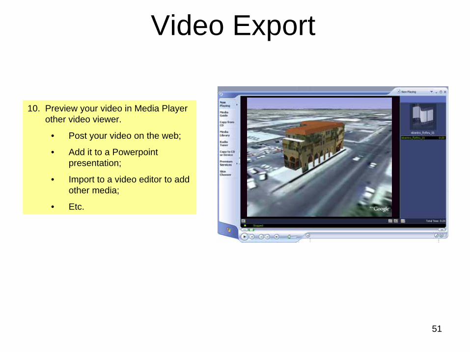
10. Preview your video in Media Player other video viewer.
• Post your video on the web;
• Add it to a Powerpoint presentation;
• Import to a video editor to add other media;
• Etc.