tool wear reduction effect of water-miscible cutting fluid · pdf filefigure 2 shows the end...
TRANSCRIPT
IOSR Journal of Engineering (IOSRJEN) www.iosrjen.org ISSN (e): 2250-3021, ISSN (p): 2278-8719 Vol. 07, Issue 03 (March. 2017), ||VX|| PP 28-40
International organization of Scientific Research 28 | P a g e
Tool Wear Reduction Effect of Water-Miscible Cutting Fluid in End Milling of Carbon Fiber Reinforced Plastic
Hironori Matsuoka1, Hajime Ono2, Takahiro Ryu1, Takashi Nakae1,
Shuichi Shuto1 and Suguru Watanabe2 1(Department of Mechanical and Energy Systems Engineering/Oita University/Japan)
Email: [email protected] 2(Yushiro Chemical Industry Co., Ltd./Japan)
Email: [email protected] Abstract: - Recently, carbon fiber reinforced plastic (CFRP) has come to be commonly used in the aviation and automobile industries. However, it is well known that CFRP is a difficult-to-cut material because it increases tool wear dramatically. This paper presents the influence of water-miscible cutting fluid on tool wear (tool life) in the end milling of CFRP. The conclusions can be summarized as follows: In down-cut milling, the tool wear is less than that in up-cut milling. The tool wear obtained with a feed rate of 100 mm/min is less than that obtained with 200 mm/min. The water-miscible cutting fluid used in the experiments reduces tool wear and improves tool life compared with the cases using dry cutting and water, irrespective of the cutting speeds. The velocity dependence is low; that is, the tool life obtained when changing the cutting speed from 69 m/min to 171 m/min is almost unchanged. The tool life curve obtained with the water-miscible cutting fluid tends to show a shortened tool life as the cutting speed is decreased, which is opposite of the tool life trend for dry cutting. The average wear rate in the initial wear region in addition to the low initial wear width affect the tool life; that is, when the wear rate is low, the tool life tends to extend. Keywords: - CFRP, Cutting, End milling, Tool life, Tool wear, Water-miscible cutting fluid
I. INTRODUCTION
In recent years, for the purpose of improving fuel economy by weight reduction, aircraft wings, tails, and bodies have been manufactured using carbon fiber reinforced plastics (CFRP). As a result, aircraft with 50 percent of the total airframe structure weight composed of CFRP have been produced. Furthermore, in the automotive industries, CFRP has been used in hoods, bumpers, and interior parts, and mass production vehicles that have adopted CFRP in the body of the main framework have been released for the first time. Moreover, CFRP applications have expanded to medical equipment and industrial parts such as tanks and pipes. CFRP has superior specific strength, specific rigidity, fatigue resistance, and wear resistance compared with metal materials, and it also has excellent corrosion resistance, low density, low coefficient of thermal expansion, and chemical stability because it is carbonaceous. In addition, since CFRP is effective for vibration suppression, it is expected that other parts in other industries will switch from conventional aluminum alloy and steel materials to CFRP to take advantage of this next-generation material.
When manufacturing a CFRP component, it is often finished into a predetermined shape by cutting (generally after integral molding). However, tool wear increases significantly, and the emission of carbon fibers and failures such as delamination degrade the finished surface properties and dimensional accuracy. In addition, CFRP is a difficult-to-cut material, and high-accuracy processing is difficult due to the uncut carbon fibers and burrs that result. Furthermore, in the case of dry machining, the carbon fiber dust generated during cutting becomes a problem for the operator, so process improvements are desired. Some research papers on the turning [1-4], drilling [5,6] and end mill processing of CFRP [7-9] have been published. However, in these papers, dry processing is used. On the other hand, while studies on the use of cutting oil in cemented carbide end mill processing have been reported [10], there are few reports that utilize cutting oil for CFRP.
In this study, the influences of the cutting method and the feed rate on the end milling processing of a CFRP plate are investigated along with the effect of water-miscible cutting fluid for different cutting speeds in terms of tool wear behavior. The results are compared with dry cutting and using water as the cutting fluid.

Paper preparation guidelines for IOSR Journal of Engineering
International organization of Scientific Research 29 | P a g e
Cutting speed
Indexable insert
100, 200 mm/minFeed rate
TPCH43R, K10, ACK300Depth of cut 0.5 mm
Tool holder FMS440
69, 93, 126, 171 m/min
Fluid supply rate 300 mL/minCFRP (100 mm×200 mm×2mm)
Table 1: Cutting tool and cutting conditions
Cutting fluid Water, Water-miscible
Work material
Figure 1: Carbon fiber stacking sequence( Surface layer: 0 °)
0°
90°
Figure 2: End milling processing of CFRP
Indexable insertCFRP
Upper acrylic plate
Lower acrylic plate
Nozzle
II. EXPERIMENTAL METHOD AND CONDITINS The experiment was conducted using a cemented carbide insert (K10 with a laminated coating of
TiAlN + AlCrN, Sumitomo Electric Hardmetal) attached to the tool holder described in Table 1. The work material was a carbon fiber reinforced epoxy resin (CFRP) and the dimensions of the CFRP plate were 100 mm in vertical length, 200 mm in horizontal length, and 2 mm in thickness. The polyacrylonitrile (PAN) carbon fibers had a diameter of 7 μm; the fiber volume fraction was 34%. Figure 1 shows a schematic of the carbon fiber stacking sequence for the CFRP specimens used in the cutting tests. The thickness of each prepreg sheet is about 250 µm. The carbon fiber orientation is such that 0° indicates the horizontal direction, and 90° indicates the vertical direction. The CFRP plate was manufactured by stacking nine prepreg sheets alternately as show in Fig. 1.
Figure 2 shows the end mill processing of CFRP. The diameter of the end mill is 40 mm, and the cutting edge has an axial rake of + 7° and a radial rake of − 4°. To eliminate vibration and/or chatter during cutting, the rigidity of the CFRP plate was enhanced by sandwiching it between two acrylic plates, and the end mill processing tests were performed repeatedly by cutting along the 200 mm length direction. A constant cutting depth of 0.5 mm was maintained, and the selected feeds were 100 and 200 mm/min. The cutting speed was varied between 69 and 171 m/min. The width of the flank wear and the width of the rake wear were estimated as illustrated in Fig. 3. The tool wear was evaluated at several cutting distance intervals, and the tool life was determined based on a flank wear of 0.25 mm and a rake wear of 0.1 mm. The properties and constituents of the water-miscible cutting fluid (hereafter, fluid) used in the experiment are shown in Table 2. The fluid was diluted with tap water at a ratio of 1:20, and it was flooded from the rake face side at a rate of 300 mL/min. The milling machine used in the tests was an MS-V vertical model manufactured by Hitachi Seiki Co., Ltd. A dust collector was fitted near the end mill as a countermeasure against the dust produced during dry cutting.
Paper preparation guidelines for IOSR Journal of Engineering
International organization of Scientific Research 30 | P a g e
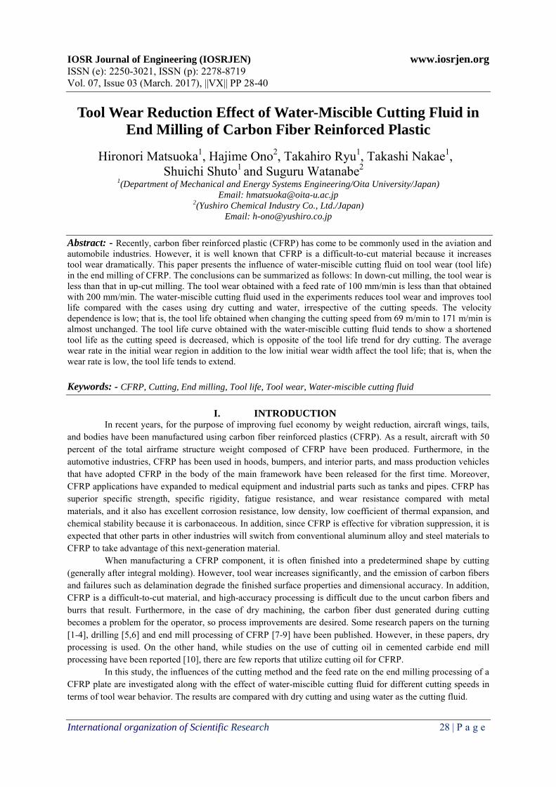
Figure 3: Wear of cutting tool
Face
VB : Width of side flank wear landVR : Width of rake wearVA : Abrasive wear
VAOriginal
Original
Original
Original
Original
Item
Appearance
Specific gravity
Synthetic lubricating additive
Mineral oil
Sulfuric EP additive
Surface active agent
pH
Surface tension
(15゚C, g/cm3)
Original
1:20
1:20
1:20 9.6
1.05
34(mN/m)
30%<
0 −10%
Fluid
Yellow liquid
Pale blue transparent
Table 2: Cutting fluid used in the test
△
●
●
▲●○▲
▲
●
△△
△△
△
△
●
▲▲
●
▲△
●
○
○○ ○ ○
○ ○○
○○
○
● ●●
●●
△ △ △ △
▲▲
▲▲
▲▲
5
Wid
th o
f too
l wea
r m
m
0.1
0.3
0.2
0 10Cutting distance m
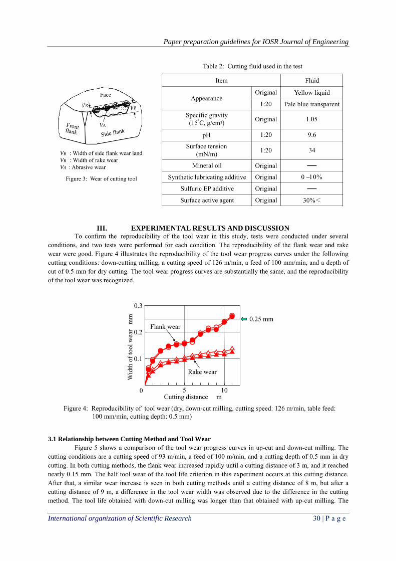
Figure 4: Reproducibility of tool wear (dry, down-cut milling, cutting speed: 126 m/min, table feed: 100 mm/min, cutting depth: 0.5 mm)
Rake wear
Flank wear 0.25 mm
III. EXPERIMENTAL RESULTS AND DISCUSSION To confirm the reproducibility of the tool wear in this study, tests were conducted under several
conditions, and two tests were performed for each condition. The reproducibility of the flank wear and rake wear were good. Figure 4 illustrates the reproducibility of the tool wear progress curves under the following cutting conditions: down-cutting milling, a cutting speed of 126 m/min, a feed of 100 mm/min, and a depth of cut of 0.5 mm for dry cutting. The tool wear progress curves are substantially the same, and the reproducibility of the tool wear was recognized.
3.1 Relationship between Cutting Method and Tool Wear
Figure 5 shows a comparison of the tool wear progress curves in up-cut and down-cut milling. The cutting conditions are a cutting speed of 93 m/min, a feed of 100 m/min, and a cutting depth of 0.5 mm in dry cutting. In both cutting methods, the flank wear increased rapidly until a cutting distance of 3 m, and it reached nearly 0.15 mm. The half tool wear of the tool life criterion in this experiment occurs at this cutting distance. After that, a similar wear increase is seen in both cutting methods until a cutting distance of 8 m, but after a cutting distance of 9 m, a difference in the tool wear width was observed due to the difference in the cutting method. The tool life obtained with down-cut milling was longer than that obtained with up-cut milling. The

Paper preparation guidelines for IOSR Journal of Engineering
International organization of Scientific Research 31 | P a g e
△
▲● ▲
●
▲●○
▲▲
△
△
△△
△
△
●
▲▲
●●
▲△
●
○
○ ○ ○
○○
○
○
○
○
● ● ●● ●
△ △ △ △
▲
▲▲
▲
▲
●
5
Wid
th o
f too
l wea
r m
m
0.1
0.3
0.2
0 10 15Cutting distance m
Figure 5: Progress curves for tool wear in up-cut and down-cut millings (dry, cutting speed: 93 m/min,table feed: 100 mm/min, cutting depth: 0.5 mm)
○
△
●
▲
DownUpFlank wearRake wear
●○
▲
0.25 mm
Up-cut milling Down-cut milling
Figure 6: Images of flank wear and rake wear in up-cut and down-cut millings (cutting speed: 93 m/min)
Rake wear
Flank wear
2 mm
Carbon Carbon
Cutting distance: 11 m Cutting distance: 13 m
rake wear obtained in both cutting methods increased rapidly until a cutting distance of 3 m, and they reached about 0.10 mm, which is more than half of the total rake wear width that occurred. Moreover, the width of the rake wear is almost the same until a cutting distance of 5 m in both cutting methods, but after a cutting distance of 5 m, the difference in the rake wear tends to become large; thus, the width of the rake wear obtained with down-cut milling is small.
Generally, in the up-cut end mill processing of steels, the cutting edge cannot cut the work material
due to the slip, and then, it can cut the material for the first time after the cutting forces act on the cutting edge to some extent. The tool wear occurs faster because of the slip of the cutting edge. On the other hand, in the case of down-cut milling, the tool wear is considered to be low because the cutting edge does not cause slip [11]. It seems to be the same cutting mechanism of the cutting edge in the end mill processing of CFRP.
Figure 6 shows a comparison of the tool wear condition between up-cut and down-cut milling at a cutting speed of 93 m/min, as shown in Fig. 5. The cutting distance is 11 m in the up-cut milling and 13 m in the down-cut milling. In both cutting methods, a difference in the wear mode for the flank wear and rake wear was not observed, and they are both assumed to be mechanical abrasion. In addition, black areas are seen where carbon powder is attached to the flank face from the cutting of the CFRP. In the case of up-cut milling, corrugated wear patterns (periodic wear) on both the rake and flank are clearly seen. However, in the case of down-cut milling, periodic wear is not seen, and nearly uniform wear has occurred.

Paper preparation guidelines for IOSR Journal of Engineering
International organization of Scientific Research 32 | P a g e
Figure 7: Images of flank wear and rake wear based on carbon fiber alignment (up-cut milling, dry, cutting speed: 93 m/min, cutting distance: 11 m)
Rake wear Flank wear
2 mm
CFRP
90°
0°Abrasive wear
Mechanical abrasion
Abrasive wear
Mechanical abrasion
(a) Carbon fiber cutting type (90° (b) Delamination type (0°
Tool Tool Work Work
Figure 8: Cutting mechanism
) )
Figure 7 shows the relationship between the CFRP orientation and the tool wear. This figure shows an enlarged view of the rake wear and flank wear for the up-cut milling case shown in Fig. 6. On the flank face, the wear mode is distinguished mechanical abrasion (white area) and abrasive wear (black area), which increase in size when cutting the prepreg sheet with a fiber orientation of 90°. For this reason, it is inferred that the tool wear increases because the cutting tool discharges the carbon fiber chips as shown in Fig. 8(a), which increases the cutting forces [12], and/or because after the carbon fibers cause elastic deformation, the carbon fibers rub the flank face of the cutting tool at the time of recovery.
In contrast, in the case of a 0° fiber orientation, delamination-type chips are discharged, as shown in Fig. 8(b), since the fibers are parallel to the cutting direction. In other words, the chips are generated as strips taken from the base material because the cutting edge bites into the carbon fiber layer, which causes bending deformation and folding of the carbon fibers. Therefore, it is presumed that the tool wear decreases due to the reduction in cutting forces. The mechanical abrasion at the flank face (white area) is a wear condition in which the coating film is scraped and the cutting tool substrate is slightly exposed. In contrast, the abrasive wear (black area) is a wear condition in which the coating film is scraped and the exposed cutting tool substrate is further scraped away.
The mechanical abrasion at the rake face (white area) is a wear condition by abrasion that occurs when
the chips are discharged in contact with the rake face. Therefore, in the case of cutting prepreg sheets with a fiber orientation of 0°, it is considered that the rake wear width increases because the contact length with the chips becomes long, since the delamination-type chips shown in Fig. 8(b) were discharged on the rake face. The abrasive wear is a recession when viewed from the flank face, and it becomes high when cutting prepreg sheets with a fiber orientation of 90°. The reason for this is presumed to be that the cutting edge cuts chips through the carbon fibers perpendicular to the cutting direction as shown in Fig. 8(a), which causes the increase in cutting forces. In the case of up-cut milling, it is thought that the rake wear increases because the rubbing is significant at the beginning of the cut.
Paper preparation guidelines for IOSR Journal of Engineering
International organization of Scientific Research 33 | P a g e
●
●●
▲
▲
●
●
▲▲▲
●
●●
●●
●
▲
▲ ▲▲▲
▲
●
●
●
●
●●
●
● ● ●● ● ●
●
▲ ▲▲▲▲
▲▲▲▲
▲▲
▲▲
▲
5
Wid
th o
f too
l wea
r m
m
0.1
0.3
0.2
0 10 15Cutting distance m
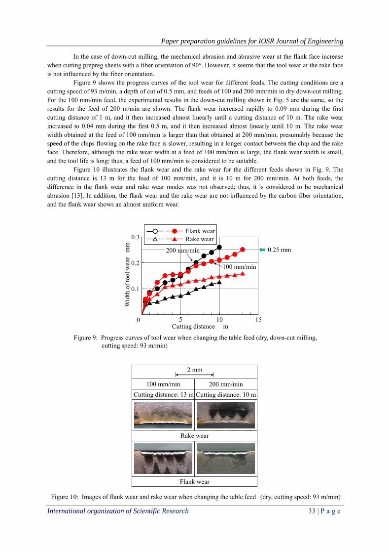
Figure 9: Progress curves of tool wear when changing the table feed (dry, down-cut milling, cutting speed: 93 m/min)
○
△
●
▲
100 mm/min
Flank wearRake wear
200 mm/min 0.25 mm
Figure 10: Images of flank wear and rake wear when changing the table feed (dry, cutting speed: 93 m/min)
Rake wear
Flank wear
2 mm
200 mm/min100 mm/minCutting distance: 13 m Cutting distance: 10 m
In the case of down-cut milling, the mechanical abrasion and abrasive wear at the flank face increase when cutting prepreg sheets with a fiber orientation of 90°. However, it seems that the tool wear at the rake face is not influenced by the fiber orientation.
Figure 9 shows the progress curves of the tool wear for different feeds. The cutting conditions are a cutting speed of 93 m/min, a depth of cut of 0.5 mm, and feeds of 100 and 200 mm/min in dry down-cut milling. For the 100 mm/min feed, the experimental results in the down-cut milling shown in Fig. 5 are the same, so the results for the feed of 200 m/min are shown. The flank wear increased rapidly to 0.09 mm during the first cutting distance of 1 m, and it then increased almost linearly until a cutting distance of 10 m. The rake wear increased to 0.04 mm during the first 0.5 m, and it then increased almost linearly until 10 m. The rake wear width obtained at the feed of 100 mm/min is larger than that obtained at 200 mm/min, presumably because the speed of the chips flowing on the rake face is slower, resulting in a longer contact between the chip and the rake face. Therefore, although the rake wear width at a feed of 100 mm/min is large, the flank wear width is small, and the tool life is long; thus, a feed of 100 mm/min is considered to be suitable.
Figure 10 illustrates the flank wear and the rake wear for the different feeds shown in Fig. 9. The cutting distance is 13 m for the feed of 100 mm/min, and it is 10 m for 200 mm/min. At both feeds, the difference in the flank wear and rake wear modes was not observed; thus, it is considered to be mechanical abrasion [13]. In addition, the flank wear and the rake wear are not influenced by the carbon fiber orientation, and the flank wear shows an almost uniform wear.

Paper preparation guidelines for IOSR Journal of Engineering
International organization of Scientific Research 34 | P a g e
●● ● ● ●
●
●
●●● ●
● ●■
●
●●
●
●
●
●
●●
●
●
●● ●
●
■
■■
■
■
■
■■
■
■
■■
■ ■■
■ ■● ■●■
5
Wid
th o
f fla
nk w
ear
mm
0.1
0.3
0.2
0 10 15 20Cutting distance m
DryWater
Fluid
(a) Flank wear
■
0.25 mm
▲ ▲▲ ▲
▲ ▲
▲▲▲▲
▲
▲▲ ▲
▲
▲
▲▲
▲
▲▲
▲
▲
▲
▲ ▲ ▲ ▲ ▲ ▲
▲
▲ ▲
◆◆ ◆◆ ◆
◆
◆◆
◆
◆
◆ ◆ ◆ ◆ ◆ ◆ ◆ ◆ ◆ ◆
5Wid
th o
f rak
e w
ear
mm
0.1
0.2
0 10 15 20Cutting distance m
Dry
Water
Fluid
(b) Rake wear
Figure 11: Progress curves of tool wear (Down-cut milling, cutting speed: 69 m/min, table feed: 100 mm/min)
▲
▲
◆
0.10 mm
From the above results, down-cut milling at a feed of 100 mm/min is suitable. Therefore, the investigation of cutting fluids is conducted under these cutting conditions. 3.2 Effect of Cutting Fluid
Since the performance of the cutting fluid is affected by the cutting speed, an experiment was conducted by changing the cutting speed. Figure 11 shows progress curves of the tool wear when using water, the fluid, and in dry cutting. The cutting speed is 69 m/min. In the case of flank wear, similar wear progress is seen until the end of the cut when using water, the fluid, and in dry cutting. The flank wear increased rapidly to about 0.13 mm during the first 5 m of cutting distance, which is about half of the tool life criterion and is considered to be initial wear. The average wear rate (the increase in the wear width per 1 m of cutting distance) obtained until a cutting distance of 5 m is 0.033 mm/m in dry cutting, 0.026 mm/m with water, and 0.025 mm/m with the fluid. The flank wear then increased almost linearly until the end of the cut, which is considered to be constant wear. The average wear rate obtained between the cutting distance of 5 m and the end of the cut is 0.011 mm/m in dry cutting, 0.011 mm/m with water, and 0.009 mm/m with the fluid; therefore, the average wear rate obtained with the fluid is low.
In the case of rake wear, about half of the rake wear width after a cutting distance of 16 m occurred
during first 1 m, and its average wear rate was 0.080 mm/m in dry cutting. It then increased almost linearly until the end of the cut with an average wear rate of 0.006 mm/m. On the other hand, when using water and the fluid, the rake wear increased almost linearly from the beginning of the cut, and the initial wear was not observed. Therefore, the average wear rate obtained from the beginning of the cut to the end of the cut was 0.006 mm/m for water and 0.005 mm/m for the fluid. The average wear rate obtained with the fluid was slightly lower than that obtained with water, and it was almost the same as that obtained by dry cutting.

Paper preparation guidelines for IOSR Journal of Engineering
International organization of Scientific Research 35 | P a g e
WaterDry
Figure 12: Images of flank wear and rake wear (down-cut milling, cutting speed: 69 m/min)
Rake wear
Flank wear
2 mm
Fluid
0.5 mm 0.5 mm
Carbon
Cutting distance: 16 m Cutting distance: 16 m Cutting distance: 20 m
Dry Fluid
2 mm
CFRP
90°
0°
Carbon
Figure 13: Images of flank wear and rake wear against carbon fiber orientation (down-cut milling, cutting speed: 69 m/min, dry: cutting distance of 16 m, fluid: cutting distance of 20 m)
Abrasive wear
Abrasive wear
Mechanical abrasion Mechanical abrasion
From the above results, the effects of the water and fluid on the flank wear were slight compared to dry cutting at a cutting speed of 69 m/min. For rake wear, the wear reduction effect from the cooling ability of water and the lubricating effect of the synthetic lubricating additive in the fluid were clearly recognized.
Figure 12 shows images of the flank wear and the rake wear at a cutting speed of 69 m/min. The differences in the wear modes of the flank wear and the rake wear were not observed in the cases of dry cutting, water, and the fluid, and it is thought that the flank wear is mechanical abrasion, and the rake wear is abrasive wear. In the case of dry cutting, significant wear appeared at the right and left sides of the flank wear (○ marks). These positions are at the upper and lower prepreg layers of the CFRP, which correspond to fiber orientations of 90°. In contrast, with water and the fluid, significant flank wear at the same positions (○ marks) is not observed. Furthermore, in the cases of dry cutting, water, and the fluid, the flank wear is affected by the fiber orientation. That is, the wear is high where the prepreg sheet has a fiber orientation of 90° (see Fig. 7). In dry cutting, black areas on the flank and rake faces can be seen, which are considered to have carbon adhered to them. In contrast, in the cases of water and the fluid, the black areas on the flank and rake faces are not observed because the carbon was washed way.
Figure 13 shows the relationship between the flank wear shown in Figure 12 and the fiber orientation of the CFRP in dry cutting and with the fluid. In both dry cutting and the fluid, the mechanical abrasion and the abrasive wear when cutting the prepreg sheet with a fiber orientation of 0° tend to be higher than when cutting the prepreg sheet with a fiber orientation of 90°. In the case of the fluid, carbon adhesion cannot be seen on the flank face.

Paper preparation guidelines for IOSR Journal of Engineering
International organization of Scientific Research 36 | P a g e
●●
●
●
●●
●
●
●
●
●
●
●
●
●
●
● ● ●
●
● ● ● ● ●
●
■
■■
■
■
■■
■
■ ■ ■
■ ■ ■ ■ ■■
■■ ■ ■
5
Wid
th o
f fla
nk w
ear
mm
0.1
0.3
0.2
0 10 15 20Cutting distance m
Dry
Water
Fluid
(a) Flank wear
0.25 mm
▲▲
▲ ▲
▲
▲
▲▲
▲▲▲▲
▲▲ ▲
▲▲
▲ ▲▲▲▲
▲▲
◆◆
◆
◆◆
◆
◆◆
◆◆
◆ ◆ ◆ ◆ ◆ ◆
◆
◆ ◆ ◆ ◆
5
Wid
th o
f rak
e w
ear
mm
0.1
0.2
0 10 15 20Cutting distance m
Dry Water
Fluid▲
(b) Rake wear
Figure 14: Progress curves of tool wear (down-cut milling, cutting speed: 171 m/min, table feed: 100 mm/min)
▲
0.10 mm
From the above results, for both dry cutting and the fluid, the mechanical abrasion is affected by the fiber orientation, and it is high when cutting the prepreg sheet with a fiber orientation of 0°. The progress curves of the tool wear at cutting speeds of 93 and 126 m/min showed nearly the same tendency as that at a cutting speed of 69 m/min, so these figures were omitted.
Figure 14 shows progress curves for the tool wear at a cutting speed of 171 m/min. In the case of the flank wear obtained by dry cutting, the flank wear increased rapidly during the first cutting distance of 4 m, reaching nearly 0.25 mm with an average wear rate of 0.06 mm/m. It then increased slowly until the end of the cut, and the average wear rate was 0.009 mm/m. In the case of water, the flank wear increased to 0.095 mm during the first 2 m, and the average wear rate was 0.048 mm/m, which is lower than that obtained by dry cutting. It then increased almost linearly until the end of the cut, and the average wear rate was 0.009 mm/m. In the case of the fluid, the flank wear increased to 0.115 mm during the first 2 m, and the average wear rate was 0.058 mm/m, which is lower than that obtained by dry cutting. It then increased more moderately and almost linearly until the end of the cut, and the average wear rate was 0.008 mm/m. In the cases of dry cutting, water, and the fluid, the rake wear increased linearly from the beginning of the cut to the end of the cut, and the average wear rates were 0.015 mm/m, 0.007 mm/m, and 0.005 mm/m, respectively. Therefore, the average wear rate with the fluid is low.
From the above results, at a high cutting speed of 171 m/min, when using water, the flank wear is low, and the tool life is prolonged compared to dry cutting. It is presumed that the cooling effect and the lubricating effect of water should be expected with an increase in cutting speed from the experimental results obtained at cutting speeds of 69, 93, 126, and 171 m/min. When using the fluid, the tool life extends slightly; thus, the effect of synthetic lubricating additives in the fluid is recognized slightly. In addition, with respect to rake wear, water works effectively compared with dry cutting, and wear is reduced by using the fluid.
Figure 15 shows images of the flank wear and the rake wear at a cutting speed of 171 m/min. In the
cases of dry cutting, water, and the fluid, differences in the wear modes for flank wear and rake wear are not observed, and it is considered that the flank wear is mechanical abrasion, and the rake ware is abrasive wear. In the case of dry cutting, the flank wear did not increase where the prepreg sheet with a fiber orientation of 0°

Paper preparation guidelines for IOSR Journal of Engineering
International organization of Scientific Research 37 | P a g e
WaterDry
Figure 15: Images of flank wear and rake wear (down-cut milling, cutting speed: 171 m/min)
Rake wear
Flank wear
2 mm
Fluid
90°
0.5 mm 0.5 mm
Cutting distance: 7 m Cutting distance: 18 m Cutting distance: 20 m
90°90°90°
■●
●
●
■
●
●
●
●
●
■
■
10
Cut
ting
spee
d
m/m
in
50
150
100
0 15 2520Cutting distance m
Dry
WaterFluid
200
5
Figure 16: Relationship between cutting speed and cutting distance (down-cut milling, tool life criterion: flank wear = 0.25 mm, table feed: 100 mm/min, cutting depth: 0.5 mm)
Flank wear
(○mark) was cut, and black areas of carbon powder adhesion on the flank and rake faces were observed. In the cases of water and the fluid, the flank wear increased to the right and left of the flank wear (○mark) compared to dry cutting. Black areas where carbon powder adhered to the flank and rake faces were not observed.
3.3 Tool Life Curve
Figure 16 shows the tool life curves for the flank wear. The tool life criterion is a flank wear width of 0.25 mm. In the case of dry cutting, the tool life increased linearly with a decrease in cutting speed, and it followed a downward-sloping curve. In contrast, the tool life decreased with a decrease in cutting speed from 171 to 93 m/min for water, which is opposite of the trend for dry cutting. As the cutting speed was decreased from 93 to 69 m/min, the tool life increased, following a downward-sloping curve. In the case of using the fluid, the tool life increased with a decrease in cutting speed from 171 to 126 m/min, following a downward-sloping curve, but as the cutting speed was further decreased from 126 to 69 m/min, the tool life decreased. When changing the cutting speed, it can be seen that the tool life is prolonged when using the fluid compared with dry cutting, and it was found that the fluid has a low cutting speed dependency because the tool life was almost the same. Although the curve for dry cutting is typical of that obtained when cutting steel, in the cases of using

Paper preparation guidelines for IOSR Journal of Engineering
International organization of Scientific Research 38 | P a g e
0.060
Aver
age
wea
r rat
e
mm
/m
69 m/min DryWaterFluid Dry WaterFluidDry Water FluidDry Water Fluid
93 m/min 126 m/min 171 m/min
Initial wear
Steady wear0.0500.0400.0300.0200.010
0
Figure 17: Comparison of average wear rate in the areas of initial wear and steady wear on the flank wear for different cutting speeds
0.0700.080
Flank wear
■
●
●
●
■
●
●
●
●
●
■
■
10
Cut
ting
spee
d
m/m
in
50
150
100
0 15 2520Cutting distance m
Figure 18: Relationship between cutting speed and cutting distance (down-cut milling, tool life criteria: rake wear = 0.10 mm, table feed: 100 mm/min, cutting depth: 0.5 mm)
Dry
Water
Fluid
200
5
Rake wear
water and the fluid, the tool life does not show a clear cutting speed dependency. Since the tool life prolonging effect from using water and the fluid is remarkably exhibited with an increase in cutting speed, it is expected that the heat problem during high-speed machining will be solved (suppression of frictional heat and removal of heat generated). This can be further studied by evaluating the fluid type, quantity of fluid supplied, and so on.
It is considered that the tool life is greatly affected by the increase in wear in the initial wear region and in the steady-state wear region. Figure 17 compares the average wear rate for the flank wear in the initial wear region and in the steady-state wear region for different cutting speeds. In the case of dry cutting, the average wear rate in the initial wear region (hereafter, initial average wear rate) tended to increase with an increase in cutting speed; the average wear rate in the steady-state wear region (hereafter, steady average wear rate) also increased from a cutting speed of 69 to 126 m/min. From this fact, it is considered that the tool life shortened as the cutting speed increased as shown in Fig. 16 because the initial average wear rate and the steady average wear rate increased. At a high cutting speed of 171 m/min, although the steady average wear rate is low, the tool life becomes short because the flank wear increased rapidly to nearly 0.25 mm in the initial wear region. The tool life is greatly related to the rapid increase in the flank wear width in the initial wear region.
In the case of water, the initial wear rate increased as the cutting speed increased. However, it showed an opposite trend to dry cutting, and the tool life prolonged with an increase in cutting speed. The steady average wear rate from a cutting speed of 93 to 171 m/min decreased as the cutting speed increased, and it is considered that the increase in the flank wear width in the steady-state wear region is related to the tool life. In
Paper preparation guidelines for IOSR Journal of Engineering
International organization of Scientific Research 39 | P a g e
0.060
Aver
age
wea
r rat
e
mm
/m
69 m/min DryWaterFluid Dry WaterFluidDry Water FluidDry Water Fluid
93 m/min 126 m/min 171 m/min
Initial wear
Steady wear0.0500.0400.0300.0200.010
0
0.0700.080
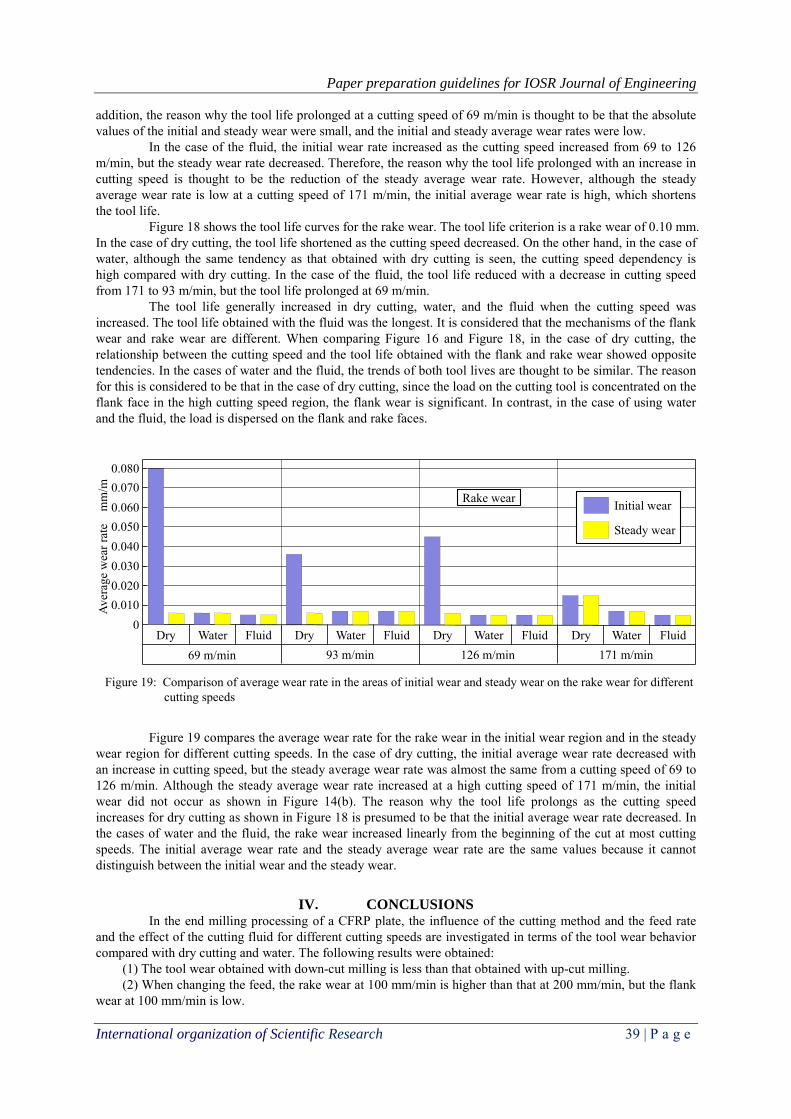
Figure 19: Comparison of average wear rate in the areas of initial wear and steady wear on the rake wear for different cutting speeds
Rake wear
addition, the reason why the tool life prolonged at a cutting speed of 69 m/min is thought to be that the absolute values of the initial and steady wear were small, and the initial and steady average wear rates were low.
In the case of the fluid, the initial wear rate increased as the cutting speed increased from 69 to 126 m/min, but the steady wear rate decreased. Therefore, the reason why the tool life prolonged with an increase in cutting speed is thought to be the reduction of the steady average wear rate. However, although the steady average wear rate is low at a cutting speed of 171 m/min, the initial average wear rate is high, which shortens the tool life.
Figure 18 shows the tool life curves for the rake wear. The tool life criterion is a rake wear of 0.10 mm. In the case of dry cutting, the tool life shortened as the cutting speed decreased. On the other hand, in the case of water, although the same tendency as that obtained with dry cutting is seen, the cutting speed dependency is high compared with dry cutting. In the case of the fluid, the tool life reduced with a decrease in cutting speed from 171 to 93 m/min, but the tool life prolonged at 69 m/min.
The tool life generally increased in dry cutting, water, and the fluid when the cutting speed was increased. The tool life obtained with the fluid was the longest. It is considered that the mechanisms of the flank wear and rake wear are different. When comparing Figure 16 and Figure 18, in the case of dry cutting, the relationship between the cutting speed and the tool life obtained with the flank and rake wear showed opposite tendencies. In the cases of water and the fluid, the trends of both tool lives are thought to be similar. The reason for this is considered to be that in the case of dry cutting, since the load on the cutting tool is concentrated on the flank face in the high cutting speed region, the flank wear is significant. In contrast, in the case of using water and the fluid, the load is dispersed on the flank and rake faces.
Figure 19 compares the average wear rate for the rake wear in the initial wear region and in the steady wear region for different cutting speeds. In the case of dry cutting, the initial average wear rate decreased with an increase in cutting speed, but the steady average wear rate was almost the same from a cutting speed of 69 to 126 m/min. Although the steady average wear rate increased at a high cutting speed of 171 m/min, the initial wear did not occur as shown in Figure 14(b). The reason why the tool life prolongs as the cutting speed increases for dry cutting as shown in Figure 18 is presumed to be that the initial average wear rate decreased. In the cases of water and the fluid, the rake wear increased linearly from the beginning of the cut at most cutting speeds. The initial average wear rate and the steady average wear rate are the same values because it cannot distinguish between the initial wear and the steady wear.
IV. CONCLUSIONS
In the end milling processing of a CFRP plate, the influence of the cutting method and the feed rate and the effect of the cutting fluid for different cutting speeds are investigated in terms of the tool wear behavior compared with dry cutting and water. The following results were obtained:
(1) The tool wear obtained with down-cut milling is less than that obtained with up-cut milling. (2) When changing the feed, the rake wear at 100 mm/min is higher than that at 200 mm/min, but the flank
wear at 100 mm/min is low.

Paper preparation guidelines for IOSR Journal of Engineering
International organization of Scientific Research 40 | P a g e
(3) The water-miscible cutting fluid used in the tests decreased the tool wear and improved the tool life compared to the cases with water and dry cutting for the different cutting speeds. The cutting speed dependency is low, and the tool life is consistent across different cutting speeds.
(4) The tool life curve obtained with the water-miscible cutting fluid tends to shorten the tool life as the cutting speed decreases, and the tendency was opposite that for dry cutting.
(5) The tool life is related to the average wear rate in the initial wear region, and the tool life tends to extend because the average wear rate is lower, and the initial wear width is small.
REFERENCES
[1] K. Sakuma, M. Seto, M. Taniguchi and Y. Yokoo, Tool Wear in Cutting of Carbon Fiber Reinforces Plastic (Influence of Tool Type), Transactions of the Japan Society of Mechanical Engineers, Series C, Vol.51, No.463, 1985, 656-666.
[2] T. Kaneeda and M. Takahashi, CFRP cutting mechanism (2nd Report) − Analysis of Depth of Reductant Uncut and Deformed Part −, Journal of the Japan Society for Precision Engineering, Vol.56, No.6, 1990, pp.1058-1063.
[3] S. Hanasaki, J. Fujiwara and M. Nomura, Tool Wear Mechanism in Cutting CFRP, Transactions of the Japan Society of Mechanical Engineers, Series C, Vol.60, No.569, 1994, 297-302.
[4] S. Hanasaki, J. Fujiwara, T. Kawai, M. Nomura and T. Miyamoto, Tool Wear Mechanism of CFRP Cutting 2, Transactions of the Japan Society of Mechanical Engineers, Series C, Vol.71, No.702, 2005. 719-724.
[5] H. Tanaka, K. Shimizu, S. Obata, R. Takizawa and K. Yanagi, Experimental study on planetary mechanism drilling for carbon fiber reinforced plastic (1st Report) − Influence of tool shape and machinability of CFRP −, Journal of the Japan Society for Precision Engineering, Vol.79, No.8, 2013, 761-765.
[6] H. Tanaka, K. Ota, H. Takeda, R. Takizawa and K. Yanagi, Experimental study on planetary mechanism drilling for carbon fiber reinforced plastic (2nd Report) − Development of inclined planetary milling spindle unit −, Journal of the Japan Society for Precision Engineering, Vol.80, No.3, 2014, 297-301.
[7] T. Inaba, A. Hosokawa, T. Ueda, T. Furomoto and R. Tanaka, End milling of CFRP − High-quality machining with high helix end mill −, Proceedings of the 2012 Japan Society for Precision Engineering Autumn Meeting, 2012, 169-170.
[8] T. Kaga, E. Shamoto, J. Tamura and M. Zaitsu, Two-section inclined end-milling to realize high-efficiency trimming of CFRP, Journal of the Japan Society for Precision Engineering, Vol.80, No.2, 2014, 183-190.
[9] T. Yashiro, Study on Cutting Mechanism in Milling Process of Crabon Fiber Reinforced Plastics (CFRP), Dr. Dissertation, Tokyo Unversity of Agrivulture and Technology, 2014, 1-157.
[10] T. Higaino, T. Aoyama and H. Ogawa, Study on end milling of CFRP with coolant and cemented carbide end mill, Journal of the Japan Society for Precision Engineering, Vol.81, No.4, 2015, 333-338.
[11] N. Takenaka, Mechanical Technology (2), 2006, 67, Corona Publishing Co., Ltd. [12] T. Kaneeda and M. Takahashi, CFRP cutting mechanism (1st Report) − Surface generation mechanism at
very low cutting speeds−, Journal of the Japan Society for Precision Engineering, Vol.55, No.8, 1989, 1456-1461.
[13] H. Takeyama, Cutting Process, 1982, 76, Maruzen Publishing Co., Ltd.