tom mcdermott, n5eg october 6, 2016 - taprn5eg/index_files/end fed half wave antenna.pdfthe end fed...
TRANSCRIPT

Tom McDermott, N5EGOctober 6, 2016
The End fed antenna is very convenient.
Where did all that RFI come from?
How come I’m getting RF bites from my equipment?
Kirchhoff's current law.
Antennas obey the law (not your opinion).

It’s very convenient.
Run the feedline to your window.
Run a half wave of wire out to a single high point (tree).
Center conductor
Shield
Egg insulatorShort length of Coax

Tom McDermott, N5EGOctober 6, 2016

It’s very convenient.
Run the feedline to your window.
Run a half wave of wire out to a single high point (tree).
Weird stuff happens…Terrible RFI, RF feedback into my MIC.
RF burns when I touch the radio chassis.
SWR changes as I move my hands.
What the heck is going on ?
Center conductor
Shield
Egg insulatorShort length of Coax
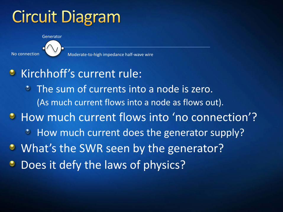
Kirchhoff’s current rule:The sum of currents into a node is zero.(As much current flows into a node as flows out).
How much current flows into ‘no connection’?How much current does the generator supply?
What’s the SWR seen by the generator?
Does it defy the laws of physics?
No connection Moderate-to-high impedance half-wave wire
Generator

Tom McDermott, N5EGOctober 6, 2016

It’s impossible to completely isolate one generator terminal.
Direct Cable feed:The outside of the coaxial cable shield is tied to the generator terminal.
Completely different currents flow on the outside vs. the inside of the shield !!
Balun feed:No balun has perfect isolation.
Any real balun has losses.
Outside of coax shield
Moderate-to-high impedance half-wave wire
Generator

Tom McDermott, N5EGOctober 6, 2016

The cable inside shield current returns back on the cable shield outside.
The cable shield forms the ‘other half ‘of the antenna.
The antenna is actually off-center fed.
The shield (hot part of antenna) is probably wired to the transmitter chassis.
Tx is ‘hot’ with RF (ouch).
Touching the transmitter changes the antenna capacitance – the SWR changes as you move around.
RFI everywhere !!

Iant must flow through the balun stray C.If the balun Z is high, then large voltages can appear across the balun. Arc arc…
If the balun is lossy, then it can dissipate a lot of power. Ferrite dust…
At 100 watts the voltage can be thousands of volts RF.
Using QRP you may never notice.

Use a ¼ wave stub to transform High-Z to Low-Z.
Commonly called “J-pole” antenna
Stub does not solve common mode problem.
No current into top of short stub leg.Current into stub legs must be equal and opposite or else the stub radiates.Feedline shield still radiates.Antenna pattern is strongly dependent on feedline, and placement.
½ w
avel
engt
h¼
wav
elen
gth
High Z
~Zero Z
50 Ω

A ¼ wave (or ¾, 5/4, etc.) wire is an impedance inverter.
If it is ‘open’ at the far end, the impedance is low at the near end.Current wants to flow into a low impedance.If it is ‘shorted’ at the far end, the impedance is high at the near end.
Above applies when in free space.When buried in the ground, its effective length changes a lot.
It is only a quarter-wave on one band.Counterpoise can be in the same plane as the antenna (i.e. dipole).

How could we make an EFHW antenna work?Need a finite impedance at both generator terminals.
A short connection to good ground is one way.
A ¼ wave wire (counterpoise) is another way.
A grounded ¼ wave wire is not a good way.
If the antenna is ½ wave, the feed will be unbalanced unless the counterpoise is also ½ wave.
A balun could deal with this provided the impedance is reasonable.