to the nasa administrator · 2.01.1974 · annual report nasa administrator aerospace safety...
TRANSCRIPT

annual report
nasa administrator
aerospace safety advisory panel
to the
by the
p a r t I -apol lo soyuz test pro jec t section 2-summary o f information
developed in the panel's fact-f inding activities
L
february 1975
AEROSPACE SAFETY ADVISORY PANEL AND STAFF
Howard K. Nason (Chairman) P r e s i d e n t Monsanto Research Corpora t ion S t . Louis , Mis sour i
D r . Cha r l e s D. Ha r r ing ton Board of D i r e c t o r s United Nuclear Corpora t ion Pasco, Washington
Hon. Frank C. D i Luzio Former Sc ience Advisor t o
S t a t e House San ta Fe, New Mexico
t h e Governor of New Mexico
M r . He rbe r t E. Grier Sen io r Vice P r e s i d e n t EG&G, Inc. L a s Vegas, Nevada
D r . Henry Rein ing Dean Emeritus and S p e c i a l A s s i s -
U n i v e r s i t y of Southern C a l i f o r n i a - Los Angeles, C a l i f o r n i a
t a n t t o t h e P r e s i d e n t
D r . I a n M. Ross Vice P r e s i d e n t f o r Network Planning
B e l l L a b o r a t o r i e s Holmdel, New J e r s e y
and Customer S e r v i c e s
L t . Gen. Warren D. Johnson, USAF D i r e c t o r Defense Nuclear Agency Washington, D. C.
M r . Lee R. Sche re r D i r e c t o r NASA Kennedy Space Center F l o r i d a
CONSULTANTS AND STAFF
M r . Bruce T. Lundin (Consu l t an t ) D r . W i l l i a m A. Mrazek (Consu l t an t ) D i r e c t o r Former D i r e c t o r of Engineer ing NASA L e w i s Research Center NASA Marsha l l Space F l i g h t Center Cleveland, Ohio H u n t s v i l l e , Alabama
Mr. G i l b e r t L. Roth S p e c i a l A s s i s t a n t NASA Headquar te rs Washington, D.C.
Mrs. V. E i l e e n Evans A d m i n i s t r a t i v e S p e c i a l i s t NASA Headquar te rs Washington, D. C.
Mr. Carl R. P r a k t i s h Execut ive S e c r e t a r y NASA Headquar te rs Washington, D. C.


ANNUAL REPORT TO THE NASA ADMINISTRATOR
by the
AEROSPACE SAFETY ADVISORY PANEL
PART I - APOLLO SOYUZ TEST PROJECT
Section 2 - Summary of Information Developed in the Panel's Fact -Finding Activities
February 1975


1.0
2 . 1 2 . 1 . 1
2 . 1 . 2
2 . 1 . 3
2.1.4 2 . 1 . 5
SECTION 2 . SUMMARY OF INFORMATION DEYELOPED IN THE PANEL'S FACT F I N D I N G A C T I V I T I E S
CONTENTS
Page
2 . 2 2 . 2 . 1 2 . 2 . 2
2 .3 2 .3 .1
INTRODUCTION . . . . . . . . . . . . . . . . . . . . 3
APOLLO . . . . . . . . . . . . Mana gemen t . . . . . . . . . . . A . Techn ica l Management System B . Personne l . . . . . . . . . C . Review Systems . . . . . . . Basic Apollo Hardware . . . . . A . Command and S e r v i c e Modules B Launch Veh ic l e C . Space S u i t s . . . . . . . . D . S p a c e c r a f t Adapter . . . . . N e w Hardware . . . . . . . . . A . Docking Module . . . . . . . B Docking System C . Experiments . . . . . . . . D . Apollo Hazard Review . . . . Apollo Mission Design . . . . . Apollo Open Work . . . . . . .
. . . . . . . .
. . . . . . . .
. . . . . . . . . . . . 5
. . . . . . . . . . 7
. . . . . . . . . . 7
. . . . . . . . . . 7
. . . . . . . . . . 8
. . . . . . . . . . 9
. . . . . . . . . . 9
. . . . . . . . . . 11
. . . . . . . . . . 1 2
. . . . . . . . . . 12
. . . . . . . . . . 1 4
. . . . . . . . . . 1 4 . . . . . . . . . . 20
. . . . . . . . . . 2 3
. . . . . . . . . . 24
. . . . . . . . . . 27
. . . . . . . . . . 28
SOYUZ . . . . . . . . . . . . . . . . . . . . . . . 31 Management . . . . . . . . . . . . . . . . . . . . . 33 Hardware . . . . . . . . . . . . . . . . . . . . . 39 A . General D e s c r i p t i o n . . . . . . . . . . . . . . 39 B . Pre-Dock Phase . . . . . . . . . . . . . . . . . 4 1
1 . Docking Ta rge t System . . . . . . . . . . . 4 1 2 . S t a b i l i z a t i o n and C o n t r o l . . . . . . . . . 43 3 . Communican System . . . . . . . . . . . . . 44 4 . T e l e v i s i o n System . . . . . . . . . . . . . 45 5 . Docking System . . . . . . . . . . . . . . . 45
C . Docked Phase . . . . . . . . . . . . . . . . . . 47 1 . S e a l s . . . . . . . . . . . . . . . . . . . 47 2 . Atmosphere . . . . . . . . . . . . . . . . . 48 3 . Environmental and L i f e Support . . . . . . . 49 4 . Communications . . . . . . . . . . . . . . . 51 5 . Pyro techn ic System . . . . . . . . . . . . . 51
J O I N T APOLLO/SOYUZ . . . . . . . . . . . . . . . . . 57 Working Group . . . . . . . . . . . . . . . . . . 57 A . Organ iza t ion . . . . . . . . . . . . . . . . . 57 B . Process . . . . . . . . . . . . . . . . . . . 57
D . J o i n t Reviews . . . . . . . . . . . . . . . . 60 C . Documentation . . . . . . . . . . . . . . . . 59
iii
CONTENTS
2 . 3 . 2 Mission Design . . . . . . . A . Command S t r u c t u r e . . . , B. Hazard Analyses . . . . . C . Mission Sa fe ty Assessment D . Contingency Planning . . E . T r a i n i n g . . . . . . . .
3.0
4.0
ATTACHMENT 1 . . . . . . . . TABLES AND FIGURES . . . . .
1
,
Page
62 62 65 69 76 78
83
87
iv

ABBREVIATIONS
ASTP .......................... ATS-6 ......................... CSM ........................... DCR ........................... DM ............................ DS ............................ DV ............................ ECS ........................... FMEA .......................... I E D ........................... JSC ........................... KSC ........................... LM ............................ LSS ........................... OM ............................ RCS ........................... SCR ........................... SLA ........................... SM ............................
Apollo Soyuz T e s t P r o j e c t App l i ca t ions Technology S a t e l l i t e Command and S e r v i c e Modules Design C e r t i f i c a t i o n Review Docking Module Docking System Descent Vehicle (Soyuz) Environmental Cont ro l System F a i l u r e Mode and E f f e c t s Analys is I n t e r a c t i n g Equipment Document Johnson Space Center , Texas Kennedy Space Center , F l o r i d a Lunar Module L i f e Support System O r b i t a l M d u l e (Soyuz) Reac t ion Con t ro l System S p a c e c r a f t Compa t ib i l i t y Review Spacec ra f t Adapter S e r v i c e Module
V

1 . 0 INTRODUCTION
1


1.0 INTRODUCTION
Section I provides the Panel's observations and conclusions on
ASTP based on its fact-finding activities to date. Attachment 1 to
that section lists these activities and the topics covered. Attach-
ment 2 includes Dr. Charles D. Harrington's observation on the joint
docking tests in Pbscow and the ASTP Program's response to his re-
commendation.
This section, Section 11, provides a summary of the information
developed during these fact-finding activities and in a review of the
extensive documentation used in the program. The information from
the various on-site visits has been consolidated and organized in the
same outline as Section I. Such a summary of data is necessarily a
compromise between comprehensiveness, detail, and brevity. It's in-
tent is to provide the reader with an idea of what the Panel has re-
viewed and a description of the program at this point. Attachment 1
includes an example of recent Panel questions and the Program's re-
sponse as an indication of the continuing dialogue.
3


2 . 1 APOLLO
5

2 1.1 MANAGEMENT
A. Technical Management System
The program management systems used in the design and production
of the Apollo spacecraft and Saturn vehicles for this mission were
essentially the same systems used to produce earlier successful Apollo
and Skylab flight systems. The Panel has monitored the evolution of
these systems over the years. Since they have been described in pre-
vious annual reports these systems are not discussed here. These
technical management systems have been adapted for the engineering
and manufacture of the new Docking Module, Docking System, and experi-
ments as well as modifications to the basic Apollo Saturn hardware.
There is a management program for monitoring and evaluating
storage and age-life effects. Implementation of this system provided
a controlled benign storage environment and assured detailed contin-
uing inspection of the flight hardware. In addition, there is a
systematic program for the replacement of items approaching or beyond
their shelf -life.
B. Personnel
The key NASA technical and management personnel bring the expe-
rience of both Apollo and Skylab to ASTP.
The number of contractor personnel has been reduced to fit the
needs of the program. Where necessary contractor management has pro-
vided additional work in related areas to maintain the proficiency
7

and morale of the people on this program.
C. Review Systems
The technical review system is as extensive as the one used on
Apollo and Skylab.
The CSM, DM, DS, and launch vehicle have been through the De-
sign certification Review process (DCR). Part I of the DCR examined
the design of new and modified elements. Part I1 examined the results
of action items from Part I and the results of major qualification
and certification tests.
In addition, management has held the following special reviews:
1. A board of experts reviewed the extent of qualification
by analysis. This board examined the following subsystems: SLA truss,
SM experiment doors and mechanisms, DM thermal blankets, DM structure,
DMhatches and mechanisms, and DM oxygen and nitrogen tanks. The re-
sults of the review were presented at a Panel session as well as at
the DCR.
2. An ASTP Engineering Review Board was established for a
"fresh look." The Board was composed principally of senior engineer-
ing directors from Apollo and Skylab. They reviewed the new flight
systems and their reconnnendations have been implemented as appropriate.
This resulted from a reconmendation by the Skylab I Investigation
Board.
ence from prior programs, including Skylab, has been used in this
program .
Such a review increases management's confidence that experi-
8

2 . 1 . 2 BASIC APOLLO HARDWARE
A. E M
The p r i m e v e h i c l e i s CSM 111. It w a s b u i l t a s a n Apollo Block I1
s p a c e c r a f t and w a s modified f o r ASTP. These m o d i f i c a t i o n s inco rpor -
p o r a t e subsequent improvements as w e l l as changes r e q u i r e d f o r t h i s
m i s s i o n .
These m o d i f i c a t i o n s have been eva lua ted du r ing the Design Certi-
f i c a t i o n Review. S a f e t y assessments were a l s o made. No s i g n i f i c a n t
new haza rds were i d e n t i f i e d .
The fo l lowing d i s c u s s i o n summarizes the major changes and t h e
b a s i s f o r conf idence i n them.
The CSM e l e c t r i c a l s y s t e m h a s been modified t o provide the capa-
b i l i t y f o r t r a n s f e r r i n g approximate ly 295 wat ts t o the docking module.
C i r c u i t w i r ing has been added between the CM and DM f o r communications,
i n s t r u m e n t a t i o n , docking s y s t e m power and c o n t r o l , and experiment pow-
e r and c o n t r o l . I n a d d i t i o n , c i r c u i t w i r ing has been added between
t h e CM and SM f o r experiment power and c o n t r o l , ATS-6 o p e r a t i o n , RCS,
and RCS thermal c o n t r o l system. Hazard and sneak c i r c u i t a n a l y s e s
i n d i c a t e no a d d i t i o n a l haza rds .
Environmental c o n t r o l system m o d i f i c a t i o n s i n c l u d e : ATS-6 amp-
l i f i e r c o l d p l a t e i n t h e SM, Dopper r e c e i v e r c o l d p l a t e s i n the SM, a
c o l d p l a t e f o r t h e e l e c t r o p h o r e s i s exper iment , and new f i t t i n g s ,
v a l v e s and l i n e s f o r t h e e l e c t r o p h r e s i s c o l d p l a t e . These modifica-
9

tions were certified based on analysis and similarity to prior sys-
tems. Heat flux densities were within demonstrated limits. Mount-
ing provisions were similar to previous installations. The vibration
environment is similar to that on Apollo and Skylab.
The telecommunications system was modified to accomodate the
requirements of the ATS-6 relay system and Soyuz interface. The
ATS-6 system is shown in Figure 1. The NASA system has been success-
fully tested. A compatibility test was conducted on an electrical
equivalent of flight hardware at JSC. Pre-flight tests will be con-
ducted at the launch sites in 1975. The compatibility test program
provided the only opportunity to interface the above equipment prior
to the mission. To protect against possible adverse affect on the
Soyuz pyrotechnic system from Apollo high energy RF sources, a high-
gain antenna scan-limit capability has been provided. It utilizes
switches providing redundant antenna position indications to the
HGA control system which contains the logic and the control output/in-
put. Two magnetic reed switches have been added to the antenna.
However, the results of recent Soviet tests may indicate that such
HGA scan-limits are not necessary because RF energy from the HGA is
sufficiently attenuated and will not trigger Soyuz pyros.
The body mounted attitude gyro in the CSM has experienced
excessive gyro response time. Two gyros (CSM 116 and 119) had such
a history and eighteen gyros
reuse. Failure analysis has
exhibited this anomaly when tested for
been hampered by the lack of repeat-
10
a b i l i t y of t h i s type of anomaly. Curren t d a t a seems t o i n d i c a t e t h a t
t h e problem i s i n t e r n a l t o t h e gyro, and i t appea r s on ly when t h e ou t -
pu t a x i s i s down. The fo l lowing a c t i o n s have been taken t o improve
program conf idence . Two gyros have been s u b j e c t e d t o teardown f a i l u r e
a n a l y s i s , twenty-two gyros have been r e b u i l t , and s i x r e b u i l t gyros
have a l r e a d y been d e l i v e r e d . The schedule c a l l s f o r t h e CSM 111 u n i t
t o be a v a i l a b l e i n February 1975, t h e CSM 119 u n i t and spares i n
March 1975.
B. Launch Vehicle
The prime launch v e h i c l e , S-IB-210, i s composed of t h e S-IB-10
f i r s t s t a g e , a n i n t e r s t a g e , t h e S-IVB-210 second s t a g e , and t h e
S-IU-210 ins t rument u n i t . The Sa tu rn I-B 209 launch v e h i c l e i s the
backup u n i t .
This v e h i c l e f o r ASTP w a s compared wi th t h e l a s t v e h i c l e used
f o r launching Skylab 4 . The d a t a i n d i c a t e s :
1. The r i g i d body and p r o p e l l a n t s l o s h s t a b i l i t y charac-
i s t i c s f o r t h i s v e h i c l e are e q u i v a l e n t o r b e t t e r than SA-208.
2 . There should be no POGO problems.
3 . The S - I V B / I U d e o r b i t procedure i s the same as i n Sky-
l a b and t h e r e are no known problem areas.
4 . Age l i m i t e d hardware h a s been examined i n d e t a i l .
There appea r s t o be no concern wi th e i t h e r f l i g h t o r spares be-
cause of age.
5. Marsha l l and t h e s t a g e c o n t r a c t o r s have reviewed a l l
11

stress c o r r o s i o n s u s c e p t i b l e materials. They have in spec ted t h e appro-
p r i a t e areas and reworked o r r ep laced items as r e q u i r e d . S t r e s s cor-
r o s i o n i n s p e c t i o n requi rements have been i n s t i t u t e d a t KSC t o a s s u r e
v i s i b i l i t y and c o n t r o l of any problems.
6. No miss ion p e c u l i a r hardware changes w e r e r e q u i r e d f o r
ASTP.
7 . There appear t o be no problems w i t h t h e ground suppor t
equipment.
C. Space S u i t s
The space s u i t s t o be used by t h e ASTP crew have been reviewed
by JSC. This P r e s s u r e Garment Assembly (PGA) i s b a s i c a l l y a n A7LB-
CMP conf igured s u i t w i th t h e cover l a y e r c r o s s s e c t i o n changed from
t h e Teflon-Beta a luminized f i l m nylon r i p s t o p c o n f i g u r a t i o n t o Teflon-
Beta PBI s i n c e no e x t r a v e h i c u l a r a c t i v i t y i s r e q u i r e d . The boots are
Skylab boo t s wi th h e e l c l i p s . I n t r a v e h i c u l a r g loves , e l e c t r i c a l h a r -
nes s , and p r e s s u r e gauge have remained unchanged. The p r e s s u r e re-
l i e f va lve h a s been d e l e t e d and a b lank f l a n g e i n s t a l l e d i n i t s p l a c e
on t h e r i g h t l e g . Q u a l i f i c a t i o n has been accomplished by s i m i l a r i t y
t o l i k e i t e m s flown on t h e Apollo and Skylab programs. There have
been no s i g n i f i c a n t t es t f a i l u r e s du r ing t h e p rocess of c e r t i f i c a t i o n .
A l l ASTP s u i t s w i l l be w i t h i n t h e age l i f e a l lowab le a t t h e t i m e of
t h e miss ion . N o new waivers w e r e r e q u i r e d f o r t h e ASTP s u i t .
D. S p a c e c r a f t Adapter Truss
The s p a c e c r a f t LEM Adapter (SLA) Truss s u p p o r t s t h e Docking
12

Module inside the adapter during the boost phase of the mission as
well as during transposition and docking with the CSM. Its truss is
also a stabilizer for the SLA during boost. Figure 2 shows the truss
within the S U on top o f the Saturn I - B launch vehicle. Docking
Module truss support fitting and truss release mechanism are shown
in Figure 3 . Truss structure consists of extruded aluminum angles
and I-beams, aluminum and titanium fittings and sheet metal. It uses
the same attachment points and the same separation and thruster hard-
ware as used for the LM. New structure is designed to avoid coupling
with the low frequency launch vehicle body modes.
Induced stresses in structural members so designed are much
lower than the allowable stress of the member. Consequently a test
program to verify structural integrity of support truss was un-
necessary. Instead, a proof test at 109% of design limit was con-
ducted on production articles as part of acceptance of the hardware.
Strength margins of safety and deflections will be determined by
analysis, with deflection measurements being taken during proof tests.
13

2.1.3 NEW HARDWARE
A. Docking Module
Docking Module i s used f o r crew t r a n s f e r between Apollo and Soyuz
s p a c e c r a f t s and as a work area f o r experiments .
Design w a s s u f f i c i e n t l y c o n s e r v a t i v e t o war ran t a minimal qua l -
i f i c a t i o n tes t program. However, module d i d undergo an e x t e n s i v e
tes t program where a p p r o p r i a t e . Th i s program inc luded a p roof -p res su re
t e s t , l e a k tests, gas s t o r a g e t ank proof p r e s s u r e and l e a k tes ts , ex-
t e r i o r thermal i n s u l a t i o n ven t t es t , breadboard system tests, environ-
mental c o n t r o l and l i f e suppor t system, and development tests of
D M / S O ~ U Z e l e c t r i c a l d i sconnec t mechanism.
on i n d i v i d u a l components such as c a u t i o n and warning d e t e c t o r s . Com-
municat ion t e s t s of VHF t r a n s c e i v e r , antenna and power d i v i d e r were
made under v a r i o u s tempera ture , v i b r a t i o n and p r e s s u r e c o n d i t i o n s .
Thermal vacuum tests supported q u a l i f i c a t i o n of a number of i t e m s
such as t h e mul t ipurpose ven t system, and environmental c o n t r o l and
l i f e suppor t system. The remaining q u a l i f i c a t i o n o r c e r t i f i c a t i o n
program w a s based on a n a l y s i s and s i m i l a r i t y .
V i b r a t i o n tests were made
Because of t h e s i g n i f i c a n c e f o r crew s a f e t y , t h e Panel gave par -
t i c u l a r a t t e n t i o n t o t h e fo l lowing areas: s t r u c t u r e , ha t ches and
seals , thermal p r o t e c t i o n , e l e c t r i c a l , and environmental and l i f e
suppor t systems,
1. S t r u c t u r e
14
Docking Module w a s designed w i t h a ve ry s t r o n g s t r u c -
t u r e . Cons t ruc t ed o f 0.625 inch , 6061 aluminum p l a t e , i t p o s s e s s e s
a n i n h e r e n t s t r e n g t h which i s s i g n i f i c a n t l y g r e a t e r than t h a t re-
q u i r e d f o r any known miss ion loads . It w a s designed f o r a ground-
l e v e l launch of t h e S-IB. The planned launch from a p e d e s t a l means
s t r u c t u r e w i l l see on ly about 25% of t h e energy l e v e l i t would have
seen i n a ground-based launch. Math models used t o d e f i n e DM s t r u c -
t u r a l r e sponse t o t h e launch are t h e s a m e as those used on Apollo and
Skylab programs.
Ana lys i s i n d i c a t e s t h a t g e n e r a l stresses i n DM s t r u c -
t u r e are ve ry low.
DM bulkhead, docking s t r u c t u r e , and DM t r u s s come t o g e t h e r (F igu res
4 and 5 ) ,
y s i s . Ex tens ive r e p a i r s were made i n t h e r i n g - t o - s h e l l weld which
i s i n t h e h i g h e s t stress area o f Docking Module. T h i s w a s r eana lyzed
and is w i t h i n l i m i t s .
An e x c e p t i o n i s t h e l o c a l area where DM c y l i n d e r ,
A c c e p t a b i l i t y of t h i s s t r u c u t r e i s based on d e t a i l e d a n a l -
There is no concern abou t f r a c t u r e mechanics because
o f t h i c k n e s s o f t h e DM o u t e r s h e l l and t h e massive s i z e o f a f law re-
q u i r e d f o r f a i l u r e . Th i s i s a l s o t r u e f o r t h e t anks .
The two gaseous oxygen and two gaseous n i t r o g e n p r e s -
s u r e v e s s e l s are made from Incone l 718 f o r g i n g s . S e c t i o n s i.n each
v e s s e l are j o i n e d by one c i r c u m f e r e n t i a l e l e c t r o n beam weld. They
o p e r a t e a t 900 p s i w i t h a s a f e t y f a c t o r of about f o u r . These
t a n k s are shown i n F i g u r e 6. There w a s some q u e s t i o n on t h e s a f e t y
15

f a c t o r of t h e j o i n t where tank mounting s t r u c t u r e a t t a c h e s t o DM.
T h i s s a f e t y f a c t o r w a s less than two. The r e s u l t s of a f u r t h e r s tudy
i n d i c a t e t h a t t h i s i s s u f f i c i e n t .
2. Hatches and Seals
The Docking Module ha t ches have a s t r u c t u r e machined
from a f o r g i n g . Hatch mechanisms are those used on Apollo. The
t echn ique used f o r a n a l y s i s of t h e ha t ches i s t h e same one used on
Apollo and Skylab, A t o o l f o r d i sassembly i n f l i g h t , i f necessa ry ,
i s a v a i l a b l e . S e a l s between t h e Docking Module forward bulkhead and
t h e Docking System (F igure 7) are c r i t i c a l . The re fo re , t hey have re-
ce ived added emphasis t o assure s t r u c t u r a l s t r e n g t h and i n s i g n i f i c a n t
leakage rates.
3 . Thermal P r o t e c t i o n
Thermal p r o t e c t i o n i s b a s i c a l l y a f f o r d e d by thermal
b l a n k e t s p l aced over t h e module. Thermal vacuum t e s t s were conducted
a t JSC between June and August 1974. S o v i e t o b s e r v e r s were p r e s e n t .
The t es t resu l t s demonstrated s a t i s f a c t o r y thermal c o n t r o l performance.
The d a t a c o r r e l a t e d w i t h t h e p r e d i c t i o n s of t h e thermal math models.
4. E l e c t r i c a l System
The Docking Module e l e c t r i c a l system d e r i v e s i t s power
from t h e Command and S e r v i c e Module. Two 28 v o l t dc buses are f ed
power f o r d i s t r i b u t i o n t o those i t e m s shown i n F i g u r e 8. E l e c t r i c a l
i n t e r f a c e connects, between t h e Docking Module and t h e Command Module
and between t h e Docking Module and Soyuz, a re shown i n F i g u r e s 9, 10,
and 11. The p a i r s o f connec to r s f o r each u n i t are i d e n t i f i e d t o pre-
c l u d e i n a p p r o p r i a t e w i r i n g connec t ions .
It w a s noted t h a t e l ec t r i ca l connec to r p i n s c a r r y i n g
experiment f u r n a c e power t o t h e Docking Module are a d j a c e n t t o p i n s
c a r r y i n g t h e Command Module e n t r y py ro techn ic c i r c u i t s . Based on
Apollo and Skylab expe r i ence t h i s has been adjudged t o be poor de-
s i g n . The ASTP program o f f i c e cons ide red r e d e s i g n . However, they
concluded it was i m p r a c t i c a l because p i n reassignment would cause
major m o d i f i c a t i o n t o CM 111 p a n e l s and bundles .
c a t i o n i n CM 119 would a f f e c t t h e i n t e r c h a n g e a b i l i t y of t h e Docking
Module.
To make t h e mod i f i -
A review was conducted t o a s s u r e c o n t i n u i t y and p in -
t o - p i n i s o l a t i o n . There w i l l be a n o t h e r review a t KSC.
5 . Environmental 8nd L i f e Support S y s t e m
I n t h e p re l aunch p r e p a r a t i o n s and p r i o r t o each crew
t r a n s f e r , t h e Docking Module is conf igu red f o r t h e s a f e e n t r y of t h e
crew. I n s t r u m e n t a t i o n i s a v a i l a b l e i n t h e Command Module's Panel 101
t o a l low review of t h e t o t a l p r e s s u r e and O 2 p a r t i a l p r e s s u r e p r i o r
t o e n t r y . R e s u l t s of t e s t i n g show t h a t even w i t h t h e "worst case"
of a i r composition a g i i b l e atmosphere was e s t a b l i s h e d upon complet ion
of t h e mixing c y c l e . Before 2nd a f t e r manning of t h e Docking Module,
crew s u i t hoses a re p l aced i n t h e Docking Module t o suppor t p rope r
mixing. As t ronau t s w i l l no t e n t e r t h e Docking Module i f t h e oxygen
p a r t i a l p r e s s u r e i s less than 165 mmhg. Each crew t r a n s f e r , t o and
17
from Soyuz, r e q u i r e s a t least one p r e s s u r i z a t i o n us ing n i t r o g e n . The
hand-held a b s o l u t e gage i s t h e primary method o f de t e rmin ing when
t h e d e s i r e d a b s o l u t e p r e s s u r e has been ach ieved i n t h e DM. The DM
c a b i n p r e s s u r e meter, t h e h a t c h d e l t a P gage and t h e CM c a b i n p re s -
s u r e gage p rov ide backup c a p a b i l i t y . Soyuz i n s t r u m e n t a t i o n i s a l s o
an a c c e p t a b l e backup t o t h e hand-held p r e s s u r e gage.
An oxygen s e n s o r i n t h e Docking Module i s used t o con-
t r o l t h e atmosphere i n t h e Docking Module d u r i n g p r e s s u r e changes.
T h i s oxygen s e n s o r c o n s i s t s o f a n e l e c t r o - c h e m i c a l c e l l , t empera tu re
compensating t h e r m i s t o r , po ten t ionmete r , a s s o c i a t e d w i r i n g , and a
connec to r . Because of i t s use i n a c r i t i c a l system, NASA and t h e
c o n t r a c t o r f o r t h e Docking Module have e v a l u a t e d t h e e f f e c t of a
f a i l e d v e n t i l a t i n g f a n on t h e s e n s o r and t h e e f f e c t o f water on t h e
membrane of t h e s e n s o r . They have a l s o reviewed t h e procedures f o r
crew e n t r y i n t o t h e DM t o assure t h a t t h e c o n f i g u r a t i o n of such i t e m s
as power, i n s t r u m e n t a t i o n , a tmospheric p r e s s u r e , and N 2 c o n c e n t r a t i o n
suppor t s a f e e n t r y .
A v e n t i l a t i o n f a n i s i n s t a l l e d a t t h e midpoint of t h e
equipment module. It draws gas i n t o t h e equipment module through a
p e r f o r a t e d p l a t e n e a r h a t c h no. 2 . The a i r is rou ted ove r two oxygen
s e n s o r s and i n t o a plenum where t h e a i r i s guided t o t h e i n l e t of t h e
v e n t i l a t i o n f an . This f an t h e n d i s t r i b u t e s t h e a i r i n t o t h e Docking
Module. A v e n t i l a t i o n d u c t i s provided t o d i r e c t gas flow from t h e
f an t o t h e DM/SOYUZ i n t e r f a c e w h i l e ha t ches Nos. 3 and 4 are open.
I n case of a f an f a i l u r e , t h e Soyuz t o DM v e n t i l a t i o n f a n can be used.
It d e l i v e r s 25% as much flow as t h e DM v e n t f a n which i s s u f f i c i e n t
t o a c h i e v e t h e d e s i r e d atmosphere mixing d u r i n g t h e p r e s s u r e a d j u s t -
ment t i m e . However, d u r i n g n i t r o g e n p r e s s u r i z a t i o n , t h e oxygen
p a r t i a l p r e s s u r e s e n s o r s w i l l n o t have s u f f i c i e n t f low p a s t them.
Thus they w i l l p rov ide ve ry low p a r t i a l p r e s s u r e r e a d i n g s . S i m i l a r l y
t h e carbon d i o x i d e r e a d i n g on t h e C O 2 s e n s o r would be e r roneous when
t h e f a n i s i n o p e r a t i v e . The thermal e f f e c t s r e s u l t i n g from an in -
o p e r a t i v e f a n appea r t o be n e g l i g i b l e w i t h r e s p e c t t o t h e o v e r a l l DM
atmospheric temperature .
would o p e r a t e a t a h i g h e r temperature than d e s i r a b l e , i t would s t i l l
m e e t t h e needs of t h e mis s ion .
While t h e a i r coo led VHF-FM t r a n s c e i v e r
On t h e whole t h e e f f e c t of t h e i n o p e r a t i v e f a n can be
m i t i g a t e d by f a c t o r s such as : s h o r t crew t r a n s f e r t i m e l i n e s , crew
movement w i t h i n t h e DM volume, use o f crew s u i t hoses f o r t h e Soyuz
f a n d u r i n g h a t c h open o p e r a t i o n , and manual f ann ing by t h e crew. The
o p e r a t i n g l i f e o f t h e v e n t i l a t i o n f a n has been proven on t h e Skylab
program where s imilar u n i t s have ope ra t ed f o r o v e r 200 days wi thou t
f a i l u r e s . A s p a r e f a n has been added t o a s s u r e crew s a f e t y .
Water condensa t ion i s n o t a n t i c i p a t e d i n t h e DM. How-
e v e r , i f condensate should r e a c h a l e v e l t h a t a f f e c t s t h e o p e r a t i o n
o f t h e oxygen s e n s o r , t h e excess condensate would evapora t e as a re-
s u l t o f t h e r e p r e s s u r i z a t i o n and /o r purge c y c l e of t h e t r a n s f e r .
Based on t h e low expectancy of excess water condensate on t h e oxygen
19

s e n s o r , no d e s i g n change o r a d d i t i o n a l t e s t i n g i s t o be done.
B. Docking System
The Docking System is designed t o meet t h e fo l lowing r e q u i r e -
ments :
1. A c t i v e Mode
(a) I n i t i a l Docking:
- a t t e n t u a t e impact energy
- prov ide c a p t u r e and al ignment
- prov ide senso ry i n d i c a t i o n s o f a c t i o n s
o r e v e n t s
(b) F i n a l Docking:
- p u l l Apollo and Soyuz t o g e t h e r
- a l i g n and compress t h e docking r i n g seals
- prov ide s t r u c t u r a l and p r e s s u r e i n t e g r i t y
- prov ide sensory i n d i c a t i o n s of a c t i o n s
and e v e n t s
(c ) P a s s i v e Mode:
- prov ide compatible i n t e r f a c e s f o r t h e
a c t i v e S o v i e t system
- prov ide sensory i n d i c a t i o n s of a c t i o n s
and e v e n t s
- prov ide backup undocking c a p a b i l i t y
Major e lements of t h e Docking System are shown i n F i g u r e 1 2 .
Details of t h e i n t e r f a c e seals a r e shown i n F i g u r e 1 3 .
20

The Docking System went through a thorough component t e s t pro-
gram which inc luded t h e l a t c h e s , a t t e n u a t o r s , sea ls , t he rma l p a i n t ,
s t r u c t u r e , c a b l e s , and gea r boxes. A f t e r system t e s t i n g i t underwent
j o i n t c o m p a t i b i l i t y t es t s w i t h t h e Russian docking system b o t h i n
t h e USA and USSR.
A s expected i n a development program, t h e Docking System had
some anomalies b u t they were minor i n n a t u r e . These anomalies and
t h e i r r e s o l u t i o n are shown i n Tab le I.
The ASTP Engineer ing Review Group g e n e r a l l y w a s s a t i s f i e d w i t h
t h e d e s i g n manufactur ing and q u a l i f i c a t i o n program.
They noted t h a t f u l l e x t e n s i o n of t h e guide r i n g had no t been
p o s s i b l e under some tes t c o n d i t i o n s .
e x t e n s i o n l i g h t ' ' i n d i c a t o r as o r g i n a l l y l o c a t e d could i n d i c a t e t h a t
a n o p e r a b l e system was i n o p e r a b l e .
r i n g extend s e n s i n g i n d i c a t o r has been implemented.
program has been completed and t h e system f u l l y ex tends w i t h t h e
a t t e n u a t o r s a t r e a l i s t i c temperature c o n d i t i o n s . I n a d d i t i o n , t h e
ASTP o r g a n i z a t i o n i s i n v e s t i g a t i n g t h e p o s s i b i l i t y o f u s ing a 300mm
l e n s w i t h t h e 35mm camera as a n independent method o f de t e rmin ing
guide r i n g e x t e n s i o n ,
It w a s a case where t h e " f u l l -
A change t o r e l o c a t e t h e gu ide
The q u a l i f i c a t i o n
Also, t h e Group noted t h a t Apollo/Skylab expe r i ence has shown
t h a t m e t a l s p r i n g s should be reviewed t o assure t h a t t h e mater ia l i s
as s p e c i f i e d . Review of t h e numerous s p r i n g s i n t h e Docking System
showed t h a t one s p r i n g u t i l i z e d on the r e t r ac t c a b l e s e c t o r s (wheels)
21

i s s u b j e c t t o stress c o r r o s i o n . The f u n c t i o n of t h e s p r i n g i s t o
p reven t c a b l e s l a c k d u r i n g docking. Table I1 shows t h e a n a l y s i s
of t h a t p a r t i c u l a r s p r i n g and is t y p i c a l of t h e review conducted
by t h e c o n t r a c t o r on a l l t h e Docking System s p r i n g s .
They reviewed t h e swaged f i t t i n g s on c a b l e s t o assure t h e i r
mechanical adequacy.
Ana lys i s showed t h a t t h e c a b l e s on t h e s t r u c t u r a l l a t c h system re-
main pre loaded fo l lowing t h e i r i n i t i a l i n s t a l l a t i o n . Furthermore,
t h e r i g g i n g of t h e s t ruc tu ra l l a t c h e s i s c a r e f u l l y monitored du r ing
acceptance tes t of t h e Docking System and swage f a i l u r e would have
been r e a d i l y d e t e c t e d . Development and q u a l i f i c a t i o n systems were
This had been a problem on p rev ious programs.
completed over a y e a r ago and t h e r e is no i n d i c a t i o n of a change
i n t h e l a t c h r i g g i n g due t o metal c reep .
The e l e c t r i c a l system p rov ides power f o r o p e r a t i o n of s i x s o l e -
no ids , t h r e e gearbox motors , s t a t u s i n g l i g h t s , tes t meter, and l i m i t
sw i t ches . C e r t i f i c a t i o n of t h i s system i s by a n a l y s i s as w e l l as
q u a l i f i c a t i o n t e s t i n g . This system has been s u c c e s s f u l l y t e s t e d by
i t s e l f and w i t h t h e Soyuz u n i t .
A Docking System al ignment p i n and socket problem showed up when
a c a b l e r e t r a c t gearbox s t a l l e d ou t approximately 0.75 inches from
f u l l r e t r a c t du r ing t h e -18' F. c o l d sc reen ing tes t .
a t r e t r a c t i n g s t a l l e d o u t . On t h e f o u r t h a t t empt t h e p i n and Dock-
i n g System d i d r e t r a c t . I n v e s t i g a t i o n showed t h a t a s l i g h t mi sa l ign -
ment of t h e p i n had been caused by t h e t es t f i x t u r e . Such a m i s -
Three a t t e m p t s
22

al ignment could happen d u r i n g i n f l i g h t docking. The p i n w a s pushed
i n t o t h e s o c k e t on docking a t an a n g l e which caused m e t a l t o d i s p l a c e
and t o bind when r e t r ac t w a s a t t empted . A new p i n w a s designed w i t h
a b e t t e r shaped head and a s l i g h t change i n t h e s o c k e t . Tests have
shown t h a t t h i s combination can b e t t e r w i t h s t a n d misal ignments . This
was shown t o S o v i e t s i n November w h i l e t h e c o m p a t i b i l i t y tes ts were
i n p r o g r e s s and t h e p i n and s o c k e t on t h e NASA hardware was changed.
T h i s problem is now cons ide red r e s o l v e d .
C . Experiments
Both l i f e s c i e n c e and a p p l i c a t i o n experiments w i l l be flown.
The l i f e s c i e n c e experiments i n c l u d e i n v e s t i g a t i o n s of t h e r a d i a t i o n
e f f e c t s of heavy charged p a r t i c l e s impinging on l i v e c e l l s and t h e
e f f e c t s o f s p a c e f l i g h t on t h e human immune system. A p p l i c a t i o n ex-
per iments w i l l i n v e s t i g a t e such areas as t h e i s o l a t i o n of medical ly
u s e f u l subs t ances and t h e zero-g p r o c e s s i n g of m a t e r i a l s . The lo-
c a t i o n of t h e experiments i s shown i n F i g u r e 13 and i s l i s t e d i n
Table 111. S a f e t y a n a l y s e s a r e proceeding on t h e fo l lowing e x p e r i -
ments :
1. MA-010 - Materials P rocess Furnace. F a i l u r e of t h e
cool-down system l i n e would c a u s e lo s s of t h e Docking Module’s i n -
t e r n a l p r e s s u r e . A 0 .5 i n c h d i ame te r o r i f i c e has been added t o t h e
e x t e r i o r ven t l i n e . An emergency p r e s s u r e r e g u l a t o r l i m i t has been
s e t . I n c a s e o f a system f a i l u r e , such as a l i n e b reak o r open
v a l v e , Docking Module p r e s s u r e w i l l be maintained above 3.5 p s i a f o r
23

15 minutes by t h e i n f l o w of 02 from t h e emergency p r e s s u r e r e g u l a t o r .
Tests are t o be completed by January 1975.
2. MA-011 - Cryogenic F reeze r . This experiment i n c l u d e s
a vacuum b o t t l e c o n t a i n i n g e i g h t pounds of l i q u i d n i t r o g e n . I f i t
were t o f a i l t h e b o t t l e could e m i t n i t r o g e n i n t o t h e s p a c e c r a f t
atmosphere. The b o t t l e i s enc losed i n a m e t a l c o n t a i n e r . I n October
1974 t h e weld i n t e g r i t y was thoroughly t e s t e d .
3 . MA-048. The s o f t x - r ay experiment has a p r e s s u r i z e d
gas supply of 15 l i t e r s of gas a t 2500 p s i . An o r i f i c e i n t h e ven t
l i n e p reven t s o v e r s t r e s s of t h e g i r t h r i n g s i n t h e SM s t r u c t u r e i f
t h e gas i s dumped.
4. MA-088. The he l ium glow experiment h a s a h i g h p r e s s u r e
gas supply of 1 . 7 l i t e r s of he l ium a t 1000 p s i a . The gas b o t t l e i s
l o c a t e d i n t h e SM. I n t e n t h e r e i s t o provide an adequate s a f e t y margin
on t h e gas p r e s s u r e b o t t l e and/or t h e u s e of a r e l i e f v a l v e wi th o r i f i c e .
5. MA-089. Batteries i n t h e Doppler t r a c k i n g experiment
must have adequate v e n t i n g of t h e c e l l s and a means t o p reven t s h o r t -
i n g p a t h s .
In o r d e r t o deve lop t h e exper iments a t minimum c o s t s , documen-
t a t i o n and t e s t i n g were reduced where p r a c t i c a l . This should n o t
i m p a c t crew s a f e t y .
D. Apollo Hazard Review
S a f e t y o r g a n i z a t i o n s a t t h e Johnson, Marsha l l and Kennedy Cen-
ters are rev iewing t h e s p a c e c r a f t , l aunch v e h i c l e and a s s o c i a t e d
24

ground suppor t equipment. T h i s review i n c l u d e s an e v a l u a t i o n of t h e
unchanged systems t o a s s u r e t h a t t hey are i n f a c t as s a f e as b e f o r e .
They are reviewing bo th t h e h i s t o r y o f t h e v e h i c l e s and t h e program
f o r d e a l i n g w i t h a g e - l i f e and stress c o r r o s i o n . M o d i f i c a t i o n s and
new equipment are, of c o u r s e , a l s o be ing e v a l u a t e d . Fo r i n s t a n c e ,
t h e s a f e t y a n a l y s i s on t h e Docking Module w a s comprehensive enough
t o cove r t h e fol lowing: l o c a t i o n and d e p t h o f threaded f a s t e n e r
h o l e s i n t h e DM s k i n , examinat ion o f d e s i g n and p roduc t ion draw-
i n g s and the a s - b u i l t v e h i c l e , t e s t r e s u l t s from development and
q u a l i f i c a t i o n tes ts , c o r r e c t i o n of anomalies r e s u l t i n g from t e s t s ,
a n a l y s e s o f t h e Docking Module from t h e p o i n t of view of s a f e t y , ade-
quacy of t h e ECS v a l v e s t o p r e c l u d e ma l func t ion d u r i n g module sepa ra -
t i o n s from launch v e h i c l e , a n a l y s i s of r e l i f e v a l v e o p e r a t i o n , impacts
of g e n e r i c f a i l u r e s i n p o t e n t i a l l y hazardous hardware, s i n g l e f a i l u r e
p o i n t i d e n t i f i c a t i o n , a c c e p t a b i l i t y of environment f o r a crewman t o
s l e e p i n t h e DM, and p r e s s u r e t a n k s (oxygen and n i t r o g e n ) f o r b u r s t
d i s c requirements and f r a c t u r e mechanics.
A sneak c i r c u i t a n a l y s i s i s be ing done on t h e i n t e g r a t e d Apollo
s p a c e c r a f t , Docking Module and Docking System.
L i g h t n i n g tests have been performed t o de t e rmine s p a c e c r a f t and
space v e h i c l e s u s c e p t i b i l i t y t o l i g h t n i n g s t r i k e s and t o an a n a l y s i s
of launch l i m i t a t i o n s . Work i s c o n t i n u i n g a t t h i s t i m e . S h i e l d s and
grounds have been designed and i n s t a l l e d a t t h e KSC on a l l exposed
c a b l e s t o reduce l i g h t n i n g e f f e c t s . An i n s u l a t e d mast and ground
25

wire system i s be ing des igned and t e s t e d for p r o t e c t i o n on t h e pad
a t KSC.
26

2.1.4 MOLL0 M I S S I O N DESIGN
A major p o r t i o n of t h e Apollo miss ion i s analogous t o t h e Skylab
CSM miss ions . The s i g n i f i c a n t d i f f e r e n c e i s t h e l e n g t h of t i m e t h e
CSM remained docked t o t h e Skylab c l u s t e r i n a p a s s i v e mode.
A comparison of t r a j e c t o r y and f l i g h t c h a r a c t e r i s t i c s shows
t h a t :
1. The launch is made from Launch Complex 39 w i t h the
t o t a l v e h i c l e s t and ing on a p e d e s t a l . CSM i n t e r f a c e s f o r pre launch
and countdown o p e r a t i o n s are similar t o those of Skylab.
2. Normal launch window f o r t h i s miss ion i s about 15 min-
u t e s . T h i s i s almost t h e same as it was f o r t h e f i r s t Skylab CSM
launch.
3 . ASTP A p o l l o w i l l be i n s e r t e d i n t o a 150/167 km o r b i t
cop lana r t o t h e Soyuz wh i l e t h e Skylab CSM was i n s e r t e d i n t o a 231/155
km o r b i t .
4 . O r b i t i n c l i n a t i o n f o r ASTP i s 51.78 degrees as com-
pared w i t h 50.8 degrees i n c l i n a t i o n f o r Skylab.
5 , Rendezvous and docking between Skylab CSM and workshop
w a s between one-manned and one-unmanned v e h i c l e wh i l e ASTP u t i l i z e s
two-manned v e h i c l e s .
27

2.1.5. OPEN WORK
On t h e whole, cha l l enges f a c i n g t h e program are n o t unusual f o r
a manned program a t t h i s s t a g e of p rogres s . Typ ica l open i tems t o
be worked o f f i n t h e t i m e ahead are:
1. Launch Veh ic l e
(a) e o n t i n u a t i o n of planned i n s p e c t i o n s on acces -
sible i t e m s t h a t are s u s c e p t i b l e t o stress co r ros ion .
(b) Monitor ing t h e s t a t u s of e x i s t i n g a f t i n t e r -
s t a g e r e a c t i o n beam shea r p i n c r a c k s on S-IV-B.
(c) Replacement of t h e w e t s l u g c a p a c i t o r i n
f l i g h t c o n t r o l computer i n t h e Ins t rument Unit .
CSM 2. - (a)
(b) Design, i n s t a l l a t i o n and tes t of ATS-6 ac -
Service Module experiement door bea r ing .
q u i s i t i o n f i l t e r i n t h e Hi-Gain Antenna system.
(c)
(d) Completion f l i g h t acceptance tes ts f o r
Completion of v ideo system changes.
s e l e c t e d experiments .
3 . Docking Module
(a) V e r i f i c a t i o n based on complet ion of t h e
t he m a 1 -va c uum t e s t . (b) Continued check of a l l a c c e s s i b l e screws
i n s e r t e d i n t o t h e main s k i n s t r u c t u r e t o assure they a re locked i n p l ace .
2 8
(c) Completion of the formal report on analysis
of the structural integrity of the Doppler antenna installation.
4. Docking System
(a) Review of the results of DS-5 and DS-7 tests
conducted in Moscow for mate/leak/functional capability.
5. U.S. Hardware Certification Program
(a) Completion of certification by analysis and
test of the thirty items open at the time of the Panel's review.
The Panel has not reviewed the work flow and test and checkout
results on the flight hardware at KSC. The plan is to cover these
areas at an appropriate time when major milestones have been accom-
plished and significant data will be available.
29


2 . 2 SOYUZ
31


2.2.1 MANAGEMENT
The fo l lowing p o i n t s were made by t h e NASA Working Group Chair-
men and o t h e r e n g i n e e r i n g and management pe r sonne l most f a m i l i a r
w i t h Soyuz. I n g e n e r a l , Soyuz management systems p rov ide program
in fo rma t ion comaprable t o t h e d a t a provided by NASA management
s y s t e m s . They observed t h a t t h e S o v i e t s must have a working c o n f i g u r a t i o n
management system because o f t h e i r a b i l i t y t o know t h e designed vs .
"as b u i l t " s t a t u s of t h e i r hardware. They a l s o have a d e t a i l e d aware-
n e s s of t h e d i f f e r e n c e s between t h e b a s i c Soyuz s p a c e c r a f t and t h e
modif ied ASTP Soyuz s p a c e c r a f t .
The Soyuz management system does n o t appear t o have s a f e t y func-
t i o n s o rgan ized fo rma l ly i n t h e s a m e s e n s e t h a t NASA has . On t h e
o t h e r hand, S o v i e t approach i s t o make s a f e t y and r e l i a b i l i t y t h e re-
s p o n s i b i l i t y o f t h e d e s i g n e r s and t o prove i t i n f l i g h t tes ts .
It has been i n d i c a t e d by t h e S o v i e t s t h a t they convene s p e c i a l
i n v e s t i g a t i o n boards, s i m i l a r t o NASA's groups, t o examine space-
c r a f t a c c i d e n t s such as w i t h Soyuz 11 and 15. F a i l u r e modes a re de-
f i n e d and f i x e s implemented as a r e s u l t of t h e s e boards examining t h e
d e t a i l s of t h e mis s ion and conduct ing necessa ry tests.
S o v i e t s tend t o have t h e i r f l i g h t and ground procedures developed
by subsystem managers w h i l e o u r s are developed by NASA miss ion p l an -
n e r s supported by t e c h n i c a l pe r sonne l .
33

NASA Working Group Chairmen have a high respect for their coun-
terparts basic technical knowledge and the application of that knOw1-
edge to their flight systems and mission operations. They stated
that Soviet members of the Working Groups have demonstrated a marked
capability for mathematical and logical analysis. They appear highly
committed by self-interest to the success of the program.
Working Group Chairmen summarized their understanding of the
test approach after witnessing some mockup, bread-board, and com-
patability tests.
Soyuz manufacturing, test and checkout, as described for the
new and modified Soyuz hardware, flow provides for the following test
program to meet the Apollo Soyuz Test Project requirements:
(a) Structural development tests of systems, subassemblies
and components.
(b) Integrated tests of systems of development hardware.
(c) Flight tests.
(d) Integrated tests of flight systems and assembled
spacecraft.
Each of these main stages of the development and qualification test
programs are briefly described below.
1. Structural Development Tests,
These tests are performed during the manufacturing period
on components, assemblies and systems to verify the adequacy of en-
gineering designs, as well as of the materials and processes used in
t h e i r f a b r i c a t i o n . Where changes t o t h e d e s i g n o r materials have
been made, r e t e s t i n g i s conducted where necessa ry . The degree o f
v e r i f i c a t i o n t e s t i n g i s g r e a t e s t f o r s p a c e c r a f t hardware systems and
components t h a t are new o r have been modif ied f o r t h e ASTP miss ion .
Those i t e m s and systems which are s t a n d a r d Soyuz equipment are sub-
j e c t e d t o t h e s t a n d a r d Soyuz v e r i f i c a t i o n tes ts .
2. I n t e g r a t e d Tests For Development Hardware.
One purpose of t h e s e t e s t s i s t o o b t a i n e n g i n e e r i n g d a t a on
major systems as l i f e suppor t , s t ruc f iu re s , and docking, They a l s o
v e r i f y o p e r a t i o n under nominal and off-nominal c o n d i t i o n s . These
t es t s u t i l i z e s u c h f a c i l i t i e s as thermal-vacuum chambers t o s i m u l a t e
f l i g h t c o n d i t i o n s . During t h i s p e r i o d of t e s t i n g , t e c h n i c a l and
f l i g h t crews r e c e i v e a c e r t a i n deg ree of "on-the-job" t r a i n i n g , l e a r n -
i n g t h e r e a l - l i f e i n t r i c a c i e s of t h e new and modif ied hardware.
t e s t program f o r t h e s e i n t e g r a t e d tes ts i s shown i n Tab le IV. An ex-
ample o f t h i s t y p e of t e s t i n g i s t h e c o m p a t i b i l i t y t es t s on docking
systems conducted i n Moscow i n November 1974. T h i s work u t i l i z e s
mock-ups as w e l l as q u a l i f i c a t i o n t e s t hardware.
3 . F l i g h t Tests.
Ground
Upon completion of t h e p rev ious t e s t s t a g e s , t h e Soyuz hardware
i s ready f o r f l i g h t t e s t s . An example i s t h e f l i g h t of Soyuz 16 i n
December 1974. During manned o r unmanned f l i g h t tes ts , t h e o b j e c t i v e s
are t o :
(a ) Confirm t h e e n g i n e e r i n g d e s i g n , f a b r i c a t i o n and tes t
35
procedures .
(b) Update t h e knowledge of n a t u r a l and induced environ-
ments and t h e i r impact on t h e f l i g h t hardware.
(c) V e r i f y t h e p re l aunch ground procedures .
(d) V e r i f y t h e adequacy o f t h e hardware t o o p e r a t e prop-
e r l y b o t h as a n independent system and as p a r t o f t h e t o t a l Soyuz
ASTP system.
During f l i g h t t es t t h e hardware i s e x e r c i s e d t o t h e d e g r e e i t
w i l l be used on t h e a c t u a l ASTP mis s ion . The e x c e p t i o n is equip-
ment r e q u i r i n g d i r e c t i n t e r f a c e w i t h t h e Apollo s p a c e c r a f t , e .g . ,
Docking System.
4 . F i n a l I n t e g r a t e d Systems T e s t i n g
V e r i f i c a t i o n tests a re conducted d u r i n g t h e f i n a l s t a g e s of
f l i g h t hardware manufactur ing and i t s p r e p a r a t i o n f o r a c t u a l f l i g h t .
These v e r i f i c a t i o n t es t s are conducted t o a s s u r e p rope r hardware
f u n c t i o n and f l i g h t r e a d i n e s s . During f i n a l assembly a t t h e manu-
f a c t u r i n g s i t e and p r i o r t o i n t e g r a t e d e l e c t r i c a l t e s t i n g o f t h e
t o t a l v e h i c l e , t h e fo l lowing major v e r i f i c a t i o n tes t s a re made:
(a ) F l u i d l i n e p r e s s u r e i n t e g r i t y check.
(b) F u n c t i o n a l v e r i f i c a t i o n o f e x t e r n a l dep loyab le equip-
ments , e .g . , docking t a r g e t s , an t enna , e t c .
( c ) E l e c t r i c a l checks on i n d i v i d u a l systems.
During t h e i n t e g r a t e d e l e c t r i c a l t e s t i n g o f t h e t o t a l s p a c e c r a f t ,
t h e i n t e r a c t i o n and t o t a l f u n c t i o n i n g of t h e e l e c t r i c a l system i s
36

checked and v e r i f i e d . These tests i n c l u d e runs under nominal and
off-nominal s i t u a t i o n s .
The s p a c e c r a f t i s then d e l i v e r e d t o the launch s i t e f o r t h e
fo l lowing tes ts :
(a) A f i n a l p r e s s u r e i n t e g r i t y check of a l l f l u i d l i n e s .
(b) F i n a l v e r i f i c a t i o n of deployable hardware.
(c ) F i n a l i n t e g r a t e d e l e c t r i c a l v e r i f i c a t i o n of t he t o t a l
s p a c e c r a f t w i t h p a r t i c u l a r a t t e n t i o n t o t h e r a d i o system.
Upon complet ion of t h e above tests, t h e s p a c e c r a f t i s prepared f o r
mat ing t o t h e launch v e h i c l e and t r a n s p o r t e d t o t h e launch pad.
I n accordance w i t h j o i n t agreements as documented i n program
IED's, t h e r e are a number of tests i n which p a r t i c i p a t i o n of both
s i d e s is worthwhile . The S o v i e t s i d e c o n s i d e r s i t d e s i r a b l e t h a t
NASA s p e c i a l i s t s p a r t i c i p a t e o r be p r e s e n t when they cG;nduct t h e
fo l lowing tests and v e r i f i c a t i o n s du r ing p r e p a r a t i o n of t h e Soyuz
s p a c e c r a f t :
(a) T e s t a c t i v i t y on t h e mockup f o r development of com-
p a t i b i l e arrangement of equipment.
(b) Compatible system t e s t i n g du r ing t h e p r e p a r a t i o n of
t h e "nominal" Soyuz a t launch area.
(c) Perform f i t - c h e c k of t h e Apollo and Soyuz docking
assembl ies p r i o r t o i n s t a l l a t i o n .
(d) T e s t o p e r a t i o n s on mockup i n connec t ion w i t h develop-
ment of t h e l i f e suppor t systems.
37

A d d i t i o n a l d e t a i l on t h e procedures used t o p repa re t h e space-
c r a f t d u r i n g manufacture and a t t h e launch area are provided i n
Table V and F igu re 15.
C o m p a t i b i l i t y tes ts conducted f o r t h e docking and r a d i o communi-
c a t i o n s systems i n d i c a t e t h a t t h e S o v i e t approach t o both t e s t i n g
and t h e t es t f a c i l i t i e s probably are comparable t o NASA's approach.
I n t h e c a s e of t e s t i n g of t h e py ro techn ic d e v i c e s , t h e S o v i e t s
a p p a r e n t l y d i d no t have an a p p r o p r i a t e power source i n t h e S-band
frequency bu t t h e y were a b l e t o m e e t t h e t es t requi rements through
o t h e r means.
The ASTP 20205 "Report on t h e Soyuz Hab i t ab le Modules Over-
p r e s s u r i z a t i o n and Depres su r i za t ion S a f e t y Assessment" d e s c r i b e s
t h e type of t e s t i n g conducted on t h e Soyuz s t r u c t u r e . A l l s t r u c t u r a l
material i s s u b j e c t e d t o x - r ay and u l t r a s o n i c checks t o a s s u r e proper
welds. It i s a l s o s u b j e c t e d t o v i b r a t i o n and proof tes ts a f t e r manu-
f a c t u r e , l eakage tes t s , s t r u c t u r a l s t r e n g t h tes ts , vacuum chamber
tes ts and i n t e g r a t e d Soyuz v e h i c l e tes ts . Valves, gas mixture s u p p l i e s ,
and s e a l s a r e a l l checked. Any i t e m which had an anomaly i n p rev ious
f l i g h t s i s a l s o r i g o r o u s l y t e s t e d .
38

2.2 .2
A. General Desc r ip t ion
The Soyuz s p a c e c r a f t c o n s i
HARDWARE
ts of f o u r s epa ra 2 and mutua l ly
suppor t ing e l emen t s : Docking Un i t , O r b i t a l Module, Descent Vehicle ,
and t h e Ins t rument Assembly Module. These a r e shown i n Figure 16 .
The Soyuz s p a c e c r a f t p r e v i o u s l y used by t h e S o v i e t s w a s b a s i c a l l y
t h e s a m e a s t h e ASTP u n i t . This s p a c e c r a f t i n c o r p o r a t e s t h e fol low-
i n g new o r modif ied f e a t u r e s .
1. New systems,
( a ) Docking and I n t e r n a l T rans fe r System
(b) Ranging and Communication System f o r Rendezvous
(c) Apollo (USA) Radio Frequency Communication System
(d) Ex te rna l L i g h t s System and Docking Targe t Assembly
(e) Cable Communication System
2 . Modified Systems.
( a ) Thermal Cont ro l System
(b) L i f e Support System
(c) Spacec ra f t s t r u c t u r e t o m e e t new and modified s y s t c v s
Soyuz compatible docking system looks very much l i k e the Apollo
system s i n c e t h e s e u n i t s a r e androgynous and must f i t t o g e t h e r a t the
i n t e r f a c e t o ach ieve s o f t and hard dock c o n d i t i o n s . The major d i f f e r -
ence i n des ign i s t h a t t he Soyuz u n i t u s e s motor-dr iven screws whi le
NASA uses motor-dr iven c a b l e s . Each coun t ry developed and f a b r i c a t e d
39

i t s own docking system independent ly . There are r i g i d i n t e r f a c e re-
qui rements .
a c t i v e o r p a s s i v e component i n t h e docking o p e r a t i o n . Th i s hardware
h a s been seen and worked on by USA per sonne l du r ing tests i n t h e USA
and t h e USSR. For a l l p r a c t i c a l purposes , t h i s i s t h e on ly f l i g h t
hardware t h a t h a s been so s c r u t i n i z e d .
Each c o u n t r y ’ s docking system can s e r v e e i t h e r as an
The s p h e r i c a l O r b i t a l Module i s used p r i n c i p a l l y by t h e crew
as a work area f o r exper iments as w e l l as f o r rest and r e l a x a t i o n .
I t s h a t c h e s i n t e r f a c e wi th t h e NASA Docking Module and t h e Soyuz
Descent Module. The O r b i t a l Module s u p p o r t s t h e Docking System,
docking t a r g e t s , and the TV/WF antenna.
Descent Vehicle i s t h e p r i n c i p a l h a b i t a t i o n and work area f o r
t h e crew dur ing launch, i n s e r t i o n i n t o o r b i t , r e - e n t r y and l and ing .
This v e h i c l e has a ha tch on i t s i n t e r f a c e wi th the O r b i t a l Module.
Ma jo r i ty of c o n t r o l s and d i s p l a y s a r e i n t h i s segment of t h e t o t a l
v e h i c l e .
The Ins t rument Assembly module c o n t a i n s t h e s t r u c t u r e f o r mating
the Soyuz on to t h e launch v e h i c l e . It c o n t a i n s t h e major components
of such c r i t i c a l s p a c e c r a f t systems as e l e c t r i c a l power g e n e r a t i o n
and c o n t r o l , envi ronmenta l c o n t r o l , and p ropu l s ion .
To compare t h e Soyuz s p a c e c r a f t wi th t h e Apollo s p a c e c r a f t :
a . Apollo S e r v i c e Module i s s i m i l a r t o Soyuz Ins t rument
Assembly Module.
b. Apol lo Command Module i s s imi l a r t o Soyuz Descent

Vehicle and p a r t s of O r b i t e r Module.
c . Apollo Docking Module i s s imilar t o Soyuz O r b i t a l
Module.
The s i z e of t h e modules can be v i s u a l i z e d from t h e i r i n t e r n a l
f r e e volumes:
a . Soyuz Descent Module 3800 l i t e r s
b. Soyuz O r b i t a l Module 6500 l i t e r s
c . T r a n s f e r Tunnel between a . and b . 400 l i t e r s TOTAL . . . . . . O . . . . . . . . . O . . 10700 l i t e r s
d. For comparisonthe Docking Module h a s a f r e e volume
of 3500 l i t e r s ,
B. Pre-dock Phase
For t h e sake of b r e v i t y , t h e systems d i s c u s s e d h e r e are those
used p r i m a r i l y du r ing t h i s p e r i o d . These a r e t h e docking t a r g e t
system, s t a b i l i z a t i o n and c o n t r o l system, p ropu l s ion system, r a d i o
communications system, and the Docking System.
1. Docking Targe t System.
Docking begins when t h e o r b i t a l parameters a r e approx-
ima te ly e q u a l and t h e two s p a c e c r a f t a r e i n v i s u a l c o n t a c t . It ends
when t h e two docking u n i t s are hard docked. Docking a l ignment tar-
g e t s provide t h e necessa ry in fo rma t ion f o r t h e crew t o o r i e n t t h e
v e h i c l e s t o t h e proper p o s i t i o n independent ly of the f l i g h t c o n t r o l
i n s t r u m e n t a t i o n and v i s u a l d i s p l a y s . Primary s i g h t i n g t a r g e t i s a
deployable Apollo-type t a r g e t mounted a t t h e f r o n t end of t h e O s b i t a l
Pbdule. A backup s i g h t i n g dev ice i s mounted on t h e a f t s e c t i o n of
41
the Descent vehicle. There is an alignment target mounted on the
Apollo Docking Wdule along the Soyuz line-of-sight for sighting
from the Descent Vehicle periscope device (Figure 1 7 ) .
NASA conducted target installation alignment tests in July 1 9 7 4 .
Tests used the Soviet docking system qualification unit using a test
fixture provided by the USA. Then the fixture was shipped to the
USSR for target alignment tests by the Soviets on their own hardware
at their own sites. Procedures for installation of the targets on
the Soyuz and definition of the verification plan for docking align-
ment targets are found in I E D 50502.2 dated August 1 5 , 1 9 7 4 . Other
IED's that apply are IED's 50201, 50004, 50202 and 50203.
Both Apollo and Soyuz have external lights along with color
schemes to aid in the docking procedure. External lights on the
Soyuz include a flashing light beacon, orientation lights and a flood
light. The Apollo and Soyuz have external lights along with color
schemes to aid in the docking procedure. External lights on Soyuz
include a flashing light beacon, orientation lights, and a flood light.
The Apollo floodlight is used to illuminate the passive Soyuz space-
craft so that the Apollo crew can determine the relative attitude
existing between the spacecraft. Docking target on the passive space-
craft may also be illuminated by the floodlight. Orientation lights
on Soyuz make it possible for the Apollo crew to determine the Soyuz's
approximate attitude while maneuvering in its near vicinity.
42

2 . Stabilization and Control
Soyuz attitude control system consists of three
elements :
(a) Two sets of attitude control reaction sys-
tem jets. Jets in one set have a 10 kg capability and the other
jets have a 1 kg capability.
pellant. They use c o m n plumbing. When the control system is
"off" gas pressurization electrovalves, tank propellant supply elec-
tro-valves, and individual jet valves are all "closed."
Both use hydrogen peroxide as the pro-
@) Corrective engine system. Main engine is
a single nozzle 419 kg thrust engine using 10 kg jets for attitude
control.
oxidizer.
nozzle set up with a maximum thrust of 411 kg, with throttleable
jets for attitude control. These engines also have common plumbing.
The electropneumatic tank pressurization and control valve pressur-
ization valves are closed when no voltage is applied to them. The
spring-loaded propellant feed-valves are also kept closed.
It utilizes bipropellant of hydrazine and nitric acid based
There is a backup engine which has a dual chamber, dual
(c) The control system - with both automatic Cosmonaut control panels contain input and manual control modes.
and display devices for stabilization and control events. Critical
c o m d unit activates the corrective engine system. There are two
Command Signal Devices each with sixteen keys for mode and system
selection. CSD units have a rotating drum with electroluminescent
43

display windows to indicate the items selected. Digital Display Unit
uses manual input for attitude and delta velocity maneuvers and indi-
cates the backup corrective engine operatipn.
the Apollo vehicle normally is active and Soyuz passive.
be able to perform stabilization and control functions in contingency
In the operational mode,
Soyuz will
cases during docked operations.
Test results of the Soviet control system have been provided by
the Soviets and analyzed by the United States. These results indicate
that the Soyuz control system provides adequate stability and con-
trollability. The limits of acceptable control modes have been iden-
tified for various mission phases associated with joint operations.
Soyuz vehicle is capable of providing control of the docked config-
uration, if necessary.
perform manual and automatic rotational maneuver, damp large initial
rates, and provide some x-axis translations. Finally, the results
indicate that the Soyuz does not produce excessive bending loads on
the docking system interface.
It has the capability to hold inertial attitude,
Test plans and scope of tests arefound in IED 50401. Apollo
and Soyuz test results are contained in IED 50403. Usable control
modes, as a result of the tests, are documented in IED 50405.
3 , Communication System.
This system is used during the pre-dock period of
rendezvous and ranging operations. The communications system com-
ponents are shown in Figure 18. NASA's discussions with Soviet tech-
44

nical personnel and cosmonauts brought out the necessity f o r radio-
silence during the period immediately preceding docking. In the
Soyuz system w k e radio commands are used in the spacecraft attitude
control system to energize and de-energize the circuits error protection
coding and a closed loop "compare before execute" procedure provides
protection against inadvertant command actions.
4 . Television System.
The Soyuz television system also i s used in rendevous
and docking maneuvers.
the ground and by the onboard crew. A camera mounted on the outside
of the Orbital Module is aligned with the vehicle x-axis. TV images
are transmitted to both an on-board-viewer and a ground-viewer.
The TV system is capable of control both by
5. Docking System.
The Docking System is analogous to Apollo's. Principal
difference is that where Apollo's system uses motor driven cables
and hydraulic attenuators, the Soyuz system uses motor driven screws.
This reflects only a difference in design philosophy. It is planned
that during the initial docking the Apollo active system w i l l capture
the passive Soyuz system. In a subsequent docking exercise the active
Soyuz system will capture the passive Apollo system. In both cases
the Apollo spacecraft will be the active vehicle for approach and
clocking maneuvers. Both sides have agreed that successful completion
of the docking compatibility tests on the flight hardware in November
1974 would "freeze" the interfacing hardware. Each country exchanged
45
a data package containing the component manufacture dimensions that
are critical to the interface of the two systems. Any waivers,
changes or modifications to these dimensions or to the design re-
quirements must be approved jointly.
The Docking System is designed to provide capture without the
use of the reaction control system thrusters. If there is a dock-
ing problem, these thrusters can be used to assure reliable capture.
Soyuz docking functions are described in I E D 50016 "Apollo
Soyuz Docking System Sequence of Docking and Undocking." Figure 19
shows the sequence of normal operations for the phase when the Soyuz
is passive and the Apollo is active. Figure 20 shows the sequence
for the phase when these roles are reversed. Docking System is in
a state of passive readiness when the guide-ring is fully retracted,
structural ring-latch active-hooks are unlocked, and the body-mounted
latches are locked.
I E D 50006 "Apollo Soyuz Systems Thermal Interface" defines the
thermal interfaces between the two spacecraft during joint mission
phases.
Development and compatibility testing, as well as the material
provided through the safety assessment reports, appear to provide
evidence that the Soyuz system does meet the system requirements.
Structural load histories for various contact conditions are con-
tained in I E D 50013 and associated Working Group No. 3 documents.
46

B. Docked Fhase
For purposes of this report, the docked phase encompasses the
time from hard-dock, through hatch-opening and joint-operations,
and concludes with hatch-closing and preparation for undocking.
Following areas are of particular significance for crew safety:
1. Seals.
After hard-docking the sealing of the interfaces be-
tween all modules of the combined Apollo/Soyuz vehicle must be assured.
This area has been thoroughly tested and analyzed by both countries.
The results of seal tests noted that they all met hardness, dimen-
sional and leakage requirements at "worst case" simulated conditions.
The force required to compress seals and achieve metal-to-metal contact, which
exceeded requirements by 400 Kg, is provided by the docking system latches.
There is little information available on the seals
and the manner of sealing the Docking System to the OM and the OM
to the DV. In "Safety Assessment Report - ASTP 20205" there is a statement that tests are conducted on the whole Soyuz vehicle as
well as on individual modules. There is also a statement that the
DV ring plane is air-tight-locked by the OM ring at the time when the
Soyuz spacecraft is assembled. The ultimate basis of confidence
is that the Soyuz seals will be exposed to the flight environment
long before the astronauts enter the Soyuz environment, Seals be-
tween modules may see new loads because of motion of the integrated
Apollo/Soyuz vehicles. This is under review.
47
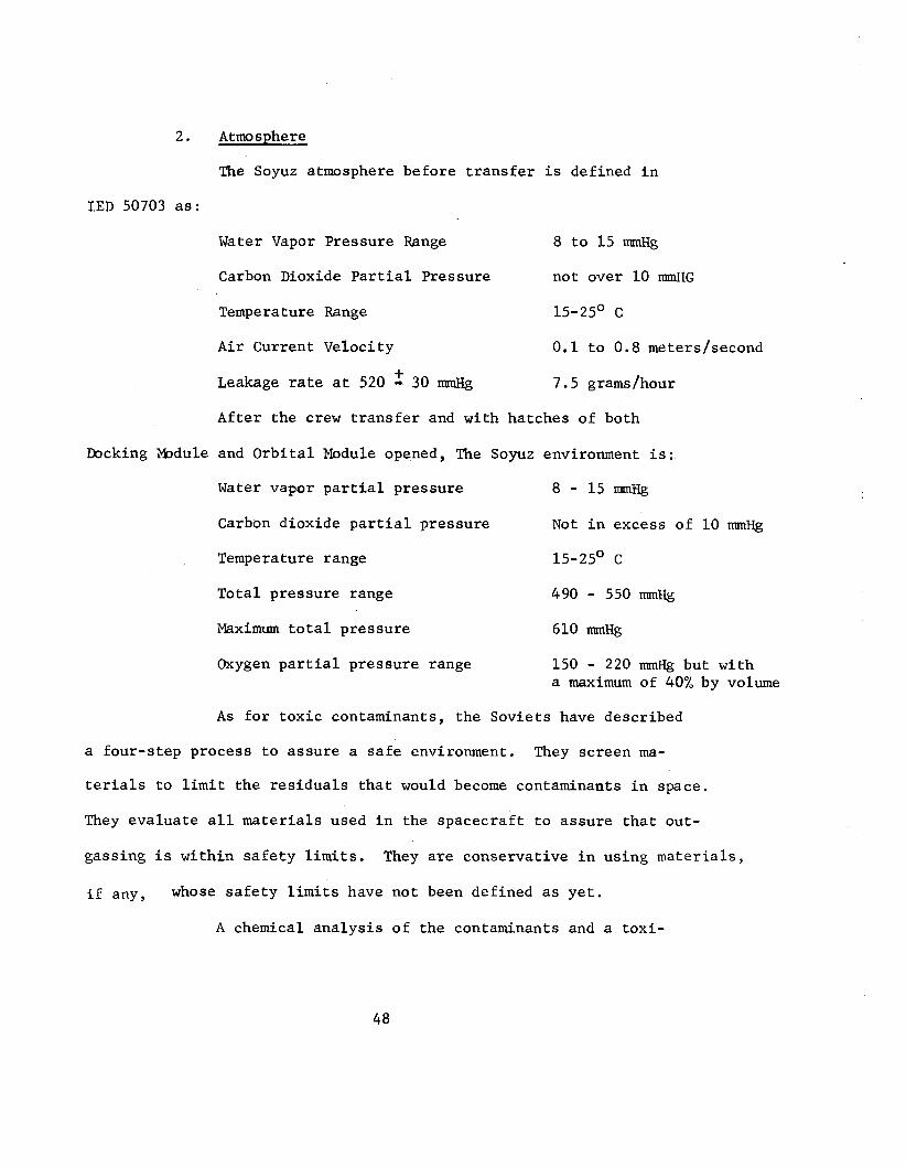
2. Atmosphere
The Soyuz atmosphere before transfer is defined in
IED 50703 as:
Water Vapor Pressure Range 8 to 15 mmHg
Carbon Dioxide Partial Pressure not over 10 rrnnH~
Temperature Range 15-25' C
Air Current Velocity 0.1 to 0.8 meters/second
Leakage rate at 520 - 30 mmHg
After the crew transfer and with hatches of both
+ 7.5 grams/hour
Docking Module and Orbital Module opened, The Soyuz environment is:
Water vapor partial pressure 8 - 15 Carbon dioxide partial pressure Not in excess of 10 mmHg
Temperature range 15-25O C
Total pressure range 490 - 550 mHg
Maximum total pressure 610 mHg
Oxygen partial pressure range 150 - 220 mmHg but with a maximum of 40% by volume
As for toxic contaminants, the Soviets have described
a four-step process to assure a safe environment. They screen ma-
terials to limit the residuals that would become contaminants in space.
They evaluate all materials used in the spacecraft to assure that out-
gassing is within safety limits.
if any,
They are conservative in using materials,
whose safety limits have not been defined as yet.
A chemical analysis of the contaminants and a toxi-
48

c o l o g i c a l e v a l u a t i o n o f t h e atmospher i s p a r t of t h e l i f e suppor t
system tests. Table V I shows t h e p e r m i s s i b l e c o n c e n t r a t i o n of assumed
t o x i c m a t e r i a l s .
Ni t rogen i s added t o the SOYUZ/DM atmosphere t o a d j u s t
t h e oxygen pe rcen tage . Thus normal o p e r a t i o n of t h e Soyuz atmos-
phere r e g e n e r a t i o n system ma in ta ins the 02 p a r t i a l p r e s s u r e w i t h i n
t h e a c c e p t a b l e range. Following volumes are used f o r a n a l y s e s :
CM 8 . 9 7 cub ic meters
CM/DM Tunnel 0.28
DM
DM/OM Tunnel
3 . 5 0
DM P o r t i o n 0.25 OM P o r t i o n 0.15
OM 6.50
DV 3.80
3. Environmental and L i f e Sirpport System.
Although NASA personnel have not seen the a c t u a l
f l i g h t hardware o r i t s p roduc t ion and t e s t i n g , t hey have had t h e
o p p o r t u n i t y t o review hardware t h a t i s desc r ibed a s i d e n t i c a l t o
the ASTP Soyuz hardware. They have seen the l o c a t i o n of t h i s hard-
wart’ i n Soyuz mockups. I n some c a s e s the i n t e r n a l p a r t s o f the hard-
ware a r e a v a i l a b l e f o r review. Elements which they have seen are:
(a) The oxygen g e n e r a t o r and C 0 2 removal dev ices i n
t h e descen t v e h i c l e .
49
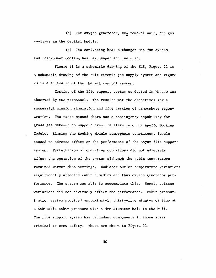
@) The oxygen generator, C 0 2 removal unit, and gas
analyzer in the Orbital Mdule.
(c) The condensing heat exchanger and fan system
and instrument cooling heat exchanger and fan unit.
Figure 21 is a schematic drawing of the ECS, Figure 22 is
a schematic drawing of the suit circuit gas supply system and Figure
23 is a schematic of the thermal control system.
Testing of the life support system conducted in Moscow was
observed by USA personnel.
successful mission simulation and life testing of atmosphere regen-
eration. The tests showed there was a contingency capability for
gross gas make-up to support crew transfers into the Apollo Docking
Module. Biasing the Docking Module atmosphere constituent levels
caused no adverse effect on the performance of the Soyuz life support
system.
affect the operation of the system although the cabin temperature
remained warmer than settings. Radiator outlet temperature variations
significantly affected cabin humidity and thus oxygen generator per-
formance. The system was able to accommodate this. Supply voltage
The results met the objectives for a
Perturbation of operating conditions did not adversely
variations did not adversely affect the performance. Cabin pressur-
ization system provided approximately thirty-five minutes of time at
a habitable cabin pressure with a 5mm diameter hole in the hull.
The life support system has redundant components in those areas
critical to crew safety. These are shown in Figure 21.
50

The system is further described in IED 50723.
4 . Cable Comunications and Radio Conununications.
The cable communications are designed principally for
use by the visiting crewmen.
cation system between the docked Apollo and Soyuz spacecraft.
system consists of audio signal cables, power cables, and television
video coaxial cables (Figure 2 4 ) . Pressure sealed feed-through con-
nectors are provided to ensure cable communications between docked
vehicles without interfering with the hatch operations at the dock-
ing interface. The astronauts manually connect the interconnecting
cables at the docking interface. Each country provides a junction
box in its spacecraft for use by the visiting crewmen. The cable
communication systems are electrically independent of the host space-
craft. Interface connector design and installation permits undock-
ing of the spacecraft even if the connectors have been left connected.
Wire sizes for these cables have been selected based on the current
flow within each spacecraft. Circuit breakers have been selected
using the same criteria. Circuit breaker acceptance criteria are
shown in Figures 25 and 26.
The system provides a hardwired communi-
This
5. Pyrotechnic System.
On the Soyuz vehicle, the pyrotechnic devices provide
for these deployment and separations:
(a) Separation of the OM and DM through the use of
pyrocartridges.
51

(b) Separation of the Apollo and Soyuz in the event
of a contingency. Explosive bolts are used.
(c) Deployment of the Soyuz parachute system.
(d) Deployment of the external elements such as
antennas and the primary docking target.
(e) Control of the hydro-pneumatic lines through the
opening and closing of valves.
The location and types of pyro devices are shown in Figure 27 and
Table VII. Table VI11 is a comparison of the Apollo and Soyuz pyro-
technic initiators. Soyuz pyrotechnics are of the bridge-wire type.
The Soyuz explosive bolt consists of a steel body with external thread
and an internal cavity for the bridge-wire type detonator. Character-
istics of the pyrocartridges are:
Bridge resistance (ohms) 0.6 to 1.2
Safe current (amps ) 0.2
Operating current for sure-fire amps 2.0
Pyrocartridge self-actuation temperature (OC)275
Operating temperature <“c) f60
Permissible shock overloads (g’ s for
5-10 millisec) 100
The characteristics of the explosive bolts are:
Bridge resistance (ohms)
Safe current (amps)
Operating current (amps)
3-8
0.05
0.6 to 0.8
52

Explosive bolt self-actuation
temperature ?C> 275
Operating temperature (OC> f60
Permissible shock overload (g's) 100
Chairman of Working Group No. 4 has told the Panel that the Apollo
and Soyuz cabling, control, and circuit protection have been jointly
reviewed and are considered safe. The characteristics of Apollo
and Soyuz pyro-device have been reviewed to limited extent. How-
ever, particular attention has been given to assuring there is no
potential hazard of RF energy igniting the pyros. Russian tests
made in November appear to have been successful in proving that
their pyros will not fire when subjected to the equivalent of a 20
to 30 db margin in RF radiated power.
53


2.3 JOINT APOLLO/SOYUZ
55

2.3 JOINT APOLLO/SOYUZ
2.3.1 Working Group
A. Organization
The five working groups have the responsibility for tech-
nical and management integration of the Apollo and Soyuz programs.
Working Group No. 1 has the responsibility for requirements, plans
and procedures for a joint mission profile, crew and mission control
centers' activities, contingency planning, and simulation and train-
ing.
guidance and control. Working Group N o . 3 has the responsibility
for the operational compatibility of the two docking systems. This
involves a number of joint test activities, including one at which
a Panel member, Dr. Charles D. Harrington, was an observer. Working
Group No. 4 has the responsibility for integrated radio communications
between Apollo and Soyuz spacecraft and the Mission Control Center.
This includes the EMI impact of one radio system on the flight
systems of the other spacecraft. Working Group No. 5 has the re-
sponsibility for life support and crew transfer systems and procedures
during both nominal and off-nominal situations. There is a sixth
11 working group" that is the forum for the Program Managers.
Working Group No. 2 has the responsibility for docking aids,
B. Process
Methods were established in document ASTP 2000 and have
evolved as the two communities have learned to work together, to
57

exchange information, and to understand the particular design or
operational philosophy of each community.
are permanent appointees.
include the appropriate engineering or operation specialists. Most
working groups have held an average of three to four meetings a year.
These include the two plenary sessions when all groups meet simul-
taneously. Problems identified by one group as not within their
province are referred t o the appropriate group for work. Communi-
cations to support thesemeetings is almost continuous as documents
and test results are exchanged, evolving issues are discussed and
agendas are established. The Soviets apparently have shown a will-
ingness to exchange information as it can be demonstrated to be needed
for a safe joint operation while maintaining their proprietary rights
in other areas.
Working Group chairmen
Membership changes as the work changes to
Interpreters used by the USA are not full-time NASA
employees. They come from industry and universities and have some
technical background. These individuals have become accustomed to
the technical systems and are fully aware of the need for exact
interpretation when dealing with technical areas in the joint work-
ing groups. Along with the Soviet interpreters, they are involved
in writing the US version and USSR version of joint documentation.
In Working Group No. 2 the Soviet personnel read, speak, and write
English well enough that most of their joint meetings are conducted
in English.
58
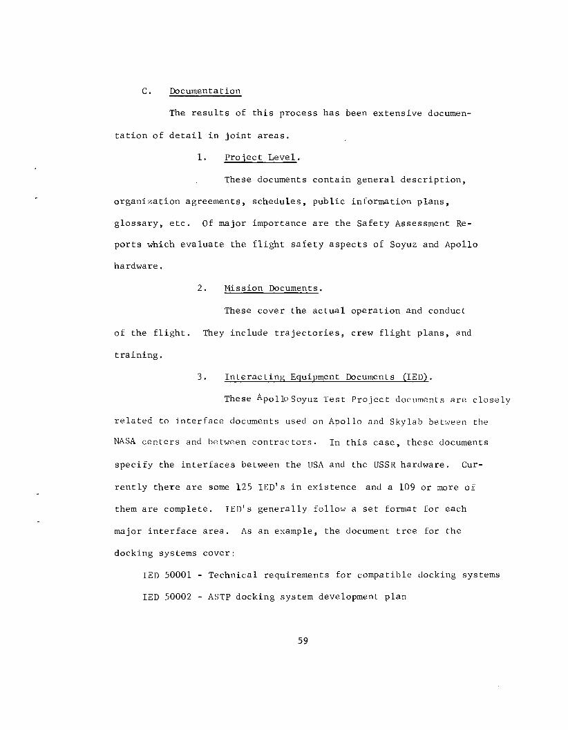
C . Documentation
The r e s u l t s of t h i s p rocess has been e x t e n s i v e documen-
t a t i o n of d e t a i l i n j o i n t a r e a s .
1. P r o j e c t Level .
These documents c o n t a i n g e n e r a l d e s c r i p t i o n ,
o r g a n i z a t i o n agreements, s chedu les , p u b l i c i n fo rma t ion p l a n s ,
g l o s s a r y , e t c . Of major importance a r e t h e S a f e t y Assessment Re-
p o r t s which e v a l u a t e t h e f l i g h t s a f e t y a s p e c t s of Soyuz and Apollo
hardware.
2 . Mission Documents.
These cover t h e a c t u a l o p e r a t i o n and conduct
of t h e f l i g h t . They i n c l u d e t r a j e c t o r i e s , crew f l i g h t p l a n s , and
t r a i n i n g .
3 . I n t e r a c t i n g Equipment Documents (IED).
These Apollo Soyuz T e s t P r o j e c t documents a r e c l o s e l y
r e l a t e d t o i n t e r f a c e documents used on Apollo and Skylab bettlreen the
NASA c e n t e r s and between c o n t r a c t o r s . I n t h i s c a s e , t h e s e documents
s p e c i f y the i n t e r f a c e s between the USA and t h e USSR hardware. Cur-
r e n t l y t h e r e a r e some 125 I E D ' s i n e x i s t e n c e and a 109 o r more of
them a r e complete. I E D ' s g e n e r a l l y fo l low a set format f o r each
major i n t e r f a c e a r e a . A s an example, t h e document t r e e f o r the
docking systems cove r :
I E D 50001 - Technica l requi rements f o r compatible docking systems
I E D 50002 - ASTP docking system development p l a n
59

I E D 50003 - Test plan f o r scale models of ASTP docking system
I E D 50004, 50005, and 50006 - Physical, load and thermal interfaces I E D 50007 - USSR ground support equipment/USA docking system
equipment, mechanical and electrical interface
- requirements
I E D 50008 - USA ground support equipment/USSR docking system equipment, mechanical and electrical interface
requirements
I E D 50009 - Joint development test plan for docking systems IED 50010 - Qualification test plan I E D 50011 - Preflight compatibility verification test plan I E D 50012 - Results of Apollo/Soyuz docking system scale model tests
I E D 50013 - Results of Apollo/Soyuz systems development tests
I E D 50014 - Results of qualification tests
4 . Working. PIrstmp Papers.
Currently NASA has developed close to 300 inter-
nal working papers to support activities of the Working Groups. The
Soviets have prepared well over 200 papers.
D. Joint Reviews
The Spacecraft Compatibility Review (SCR) is a joint
operation between the USA and the USSR. Its purpose is to review
each country's installation design against the I E D requirements.
Dates for the SCR are found in the latest issue of ASTP 30000.
The Equipment Acceptance Review (EAR) completes the assess-
60

ment of each country's exchanged equipment.
completion of all joint and integrated testing. Based on this
review the decision is made to certify the equipment as suitable
for flight.
This is held after
Configuration of interfacing hardware is jointly con-
trolled after joint qualification/compatibility tests, and the
joint equipment acceptance review. In addition, each side assesses
their own hardware to meet their own total mission plan. Dates for
the FRR are designated in the latest edition of ASTP 30000.
The Joint Flight Readiness Review provides the oppor-
tunity fo r flight hardware, joint assessment of the supporting
equipment and operations to assure they support launch schedules and
mission operations.
61

2.3.2 MISSION DESIGN
Mission planning is described in varying detail in the Mission
Operations Plan (ASTP-40400); Control Centers Interaction Plan (ASTP-
40401) ; Joint Crew Activities Plan (ASTP-40301) ; and Onboard Joint
Operations Instructions (ASTP-40600). What is chosen for a brief
review here are those areas of particular significance for crew
safety. These areas include: (1) development of the cormnand struc-
ture for situations both nominal and contingencies, (2) analyses of
hazards and development of appropriate contingency planning, and
(3) training for ground controllers and flight crews.
A. Command Structure
1. Nominal
The rules for "command and control" during nominal
situations can be summarized as follows:
(a) Flight operations are directed by flight directors
according to joint documentation.
@ ) Communications between control centers will con-
sist of voice, teletype, facsimile, and TV transmissions.
(c) Each side will appoint a groups of technical
specialists to assist in the other country's center.
(d) Joint training of crew and ground personnel, in-
cluding simulations will be conducted.
(e) Each side is responsible for its own spacecraft.
62
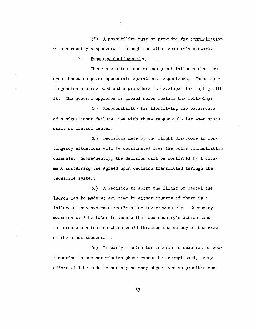
(f) A possibility must be provided for communication
with a country's spacecraft through the other country's network.
2. Examined Contingencies
These are situations or equipment failures that could
occur based on-prior spacecraft operational experience. These con-
tingencies are reviewed and a procedure is developed for coping with
it. The general approach or ground rules include the following:
(a) Responsibility for identifying the occurrence
of a significant failure lies with those responsible for that space-
craft or control center.
@) Decisions made by the flight directors in con-
tingency situations will be coordinated over the voice communication
channels. Subsequently, the decision will be confirmed by a docu-
ment containing the agreed upon decision transmitted through the
facsimile system.
(c) A decision to abort the flight or cancel the
launch may be made at any time by either country if there is a
failure of any system directly affecting crew safety. Necessary
measures will be taken to insure that one country's action does
not create a situation which could threaten the safety of the crew
of the other spacecraft.
(d) If early mission termination is required or con-
tinuation to another mission phase cannot be accomplished, every
effort will be made to satisfy as many objectives as possible con-
6 3
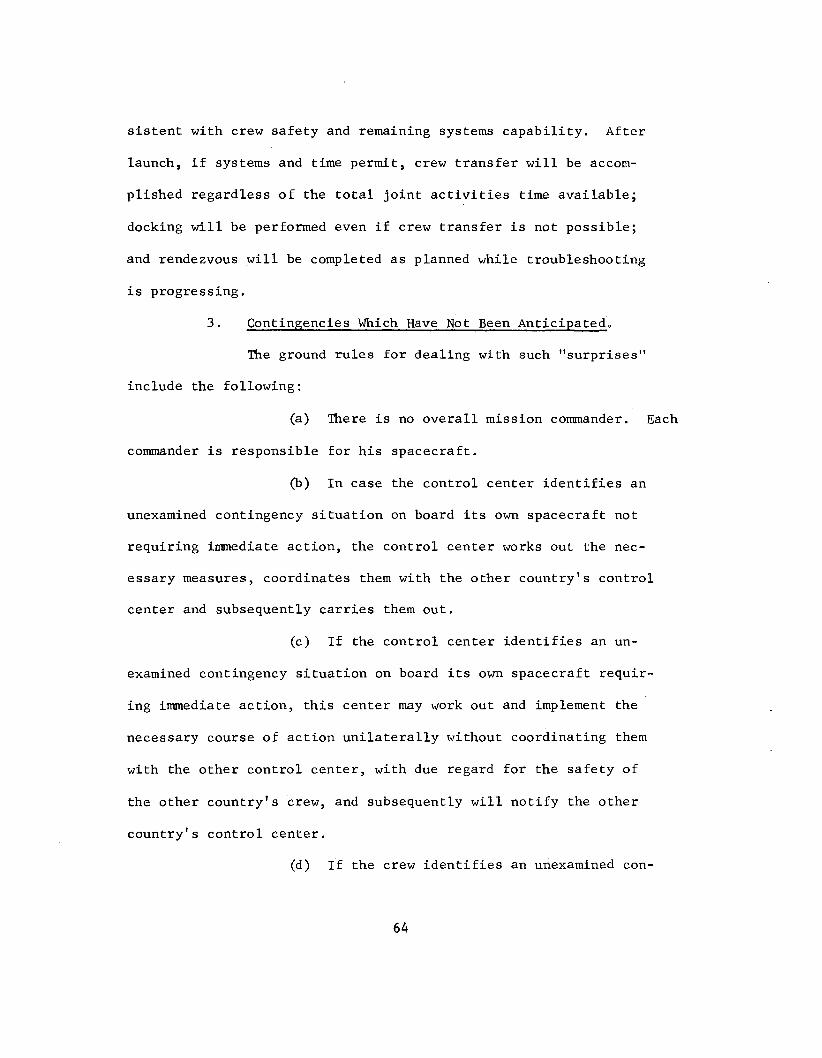
sistent with crew safety and remaining systems capability. After
launch, if systems and time permit, crew transfer will be accom-
plished regardless of the total joint activities time available;
docking w i l l be performed even if crew transfer is not possible;
and rendezvous will be completed as planned while troubleshooting
is progressing.
3 . Continpencies Which Have Not Been Anticipated.
The ground rules for dealing with such "surprises"
include the following:
(a) There is no overall mission commander. Each
commander is responsible for his spacecraft.
(b) In case the control center identifies an
unexamined contingency situation on board its own spacecraft not
requiring immediate action, the control center works out the nec-
essary measures, coordinates them with the other country's control
center and subsequently carries them out.
(c) If the control center identifies an un-
examined contingency situation on board its own spacecraft requir-
ing immediate action, this center may work out and implement the
necessary course of action unilaterally without coordinating them
with the other control center, with due regard for the safety of
the other country's crew, and subsequently will notify the other
country's control center.
(d) If the crew identifies an unexamined con-
64

tingency situation not requiring immediate action, the spacecraft
commander reports to the control center and acts in accordance : ~ i t l ~
ins tr'uc t ions.
(e) In case the crew identified an unexamined
contingency situation requiring immediate action, the spacecraft
commanders act according to a mutually agreed plan and inform the
control centers.
(f) In case the crew identifies an unexamined
contingency situation requiring immediate action, and coordination
between the spacecraft commanders is not possible, the decisions are
made by the spacecraft commanders independently, with due regard to
the safety of the other spacecraft's crew. Subsequently, the space-
craft commanders inform the control centers.
B. Hazard Analyses
The identification of hazards during the joint phase begin: ;
with the joint safety reports. These reports were prepared by each
country, on its hardware, and provide the other country with an
assessment of the safety and hazards. These assessments cover the
following areas: docking and ring latches, propulsion and control,
fire, pyros, and pressurization and communications. As the working
groups evolved, additional information became available arid this en-
abled NASA to prepare more detailed analyses. The scope and con-
clusions of these expanded safety studies prepared by NASA and as
nresented to the Panel are summarized here,

1. Pyrotechnic Devices.
A review of Soyuz-Apollo interfaces show that the
failure of any Soyuz device to function will not compromise crew
safety. The safety assessment also considers the hazard of pre-
mature firing, through such possibilities as inadvertent crew oper-
ations, auto ignition capability, firing circuit failure, spurious
signals, high shock level and ignition from an Apollo source. Their
conclusion at this time is that there are sufficient safeguards
against a firing being induced by Soyuz malfunctions. Compatibility
of Soyuz devices in the Apollo environment can be established
after a complete review of the results from the completed full scale
tests. Soyuz pyro-devices will be considered safe for the joint
mission upon the acceptable presentation of the full scale test re-
sults by the USSR at the January Joint Meeting.
2. Propulsion and Control.
JCS's Safety Office reviewed the capability of Soyuz
to support predocking maneuver requirements, to maintain attitude
for guide ring contact and capture, and to perform contingency
attitude control. They also investigated failures that could cause
loss of maneuver capability, loss of attitude hold capability, in-
advertent thruster firing, or l o s s of docking capability. Finally,
they considered the functional redundancies in sensors, control mode
selection, thruster selection, and propellant supply. Their assess-
ment concludes that the Soyuz control system has functional redundancy

to maintain a stable attitude for guide ring contact. They have not
identified any single functional failures that would cause l o s s of
attitude control. A single functional failure could result in an
inadvertent thruster firing but the thruster manifolds can be iso-
lated. Functional redundancy exists for the Soyuz sensors, control
mode selection, and propellant supply. A thruster failing in the
"on" mode would cause l o s s of that thruster. However, there is func-
tional redundancy for nominal docking and docked contingency attitude
control.
The open items to be closed at the January Working Group meeting
include documentation on tank safety factors and further detail on
the relay voting for dropout of faulty signals.
3 . Electrical Power System.
There is no interchange of power between spacecraft.
Soyuz is powered down while docked. The analysis of the electrical
power system shows that the Soviet design approach provides for
safety through tuo-wire distribution circuits, venting of battery
hydrogen, flame retardant cable casing, safety guards on switches
to critical circuits to prevent inadvertent actuation, voting logic
in automatic controls, overload protection, current limiting resistors
in pyrotechnic circuits, and series redundancy switching to prevent
short-circuit actuation. The general conclusion at this time is
that the safety approach is satisfactory. Open items to be resolved
in the January meeting include control of the charging current,
67

criteria for circuit protection and testing for component grounding.
4 . Controllable Penetrations.
JSC's Safety Office evaluated Soyuz valves exposed
to the vacuum of space and controllable by crew actions or system
operations. Their assessment also covered the depressurization de-
tection system and the capability for atmosphere replenishment.
Given the redundancy in the valves and detection system, as well as
the operational procedures, their conclusion is that there are no
constraining concerns or open safety issues.
5. Environmental Control System.
The elements of the atmosphere maintenance system
have been reviewed. These elements include the subsystems for
atmospher regeneration, gas analysis, pressure integrity check,
pressure venting and equalization, module pressurization, gas mix-
ture, and expansion bladder pressurization. The conclusion of the
Safety Office is that hazards have been reduced to an acceptable
level. Their assessment of the thermal control system is that the
hazards here have also been reduced to an acceptable level, No
hazards were identified in the water and waste management systems.
Hazards in food supply and personal hygiene are considered to be
minimal and acceptable. A review of the Soviet toxicity test and
control program leads NASA to conclude that concentrations of con-
taminants will be kept below harmful levels. Therefore, there are
no constraining concerns or open safety issues in the environmental
68