to study and do theoretical analysis of compact heat...
TRANSCRIPT

To Study and Do Theoretical Analysis
of Compact Heat Exchangers
Presented By:ME16
Group Id:130009401
Patel Jignesh A. (10ME17)
Patel Ravi R. (10ME19)
Patel Hardik A. (10ME15)
Patel Bhavesh A.(10ME09)
Guided By:
Prof. R.N.Mevada1
Definition:-
• Heat exchanger:
It is a device that provides exchange of thermal energy
between two or more fluids at different temperature.
• Types of heat exchanger:-
1. Double-Pipe heat exchangers
2. Shell and tube Heat Exchangers
3. Compact heat exchanger
4. Gasketed Plate heat exchanger
5. Condenser and evaporator
2

Compact Heat exchanger
• Types:-
1. Plate fin and tube fin
2. Tube boundle with small dia.
A heat exchanger having a surface area density greater than
about 700 m2/m3 is quite arbitrarily to as a compact heat
exchanger.
3

Fin and Tube Heat Exchanger : A Compact Heat
Exchanger
4

Applications
• Vehicular heat exchanger
• Condenser and evaporaters
• Refrigeration industry
• Aircraft oil coolers
• Automative radiators
• Oil coolers
• Intercoolers of compressors
• Other industries
5

INTRODUCTION
• This proposed scheme analyzes the heat transfer process
involved in the operation of an automotive radiator. The
analysis of a radiator encompasses nearly all of the
fundamentals discussed in a heat transfer class, including the
internal and external fluid flow through a heat exchanger and
the design and analysis of heat sinks and exchangers.
• The theoretical heat exchanger investigation begins with
analyzing the internal fluid flow through the radiator’s
circular or noncircular tubes, yielding the convective heat
transfer coefficient for water.
6

• The external fluid flowing across the radiator tubes and fins is
then analyzed to find the convective heat transfer coefficient
for the air.
• The heat sink design of the radiator must then be analyzed
using the Effectiveness method to find the theoretical
effectiveness
• This topic is specifically selected to integrate the numerous
areas from the subject of heat transfer. Through the many
challenges and successes met during this project.
7

• The convective heat transfer between a wall and the fluid is
given by
Q= hA(Tw -Tf)
Or
Q=(hA)p (Tw- Tf)
• Enhancement ratio:
E = hA/(hA)p
8

There are several methods to increase the hA
value:
• The heat transfer coefficient can be increased without an
appreciable increase in surface area.
• The surface area can be increased without appreciable changes
in the heat transfer co-efficient.
• Both the heat transfer coefficient and the surface area can be
increased.
9

OBSERVATION
EXPERIMENTAL SETUP
OBJECTIVE
RESEARCH
LITERATURE SURVEY
METHODOLOGY
10

TASK IS OVER
CONCLUSION
SOFTWARE DESIGN
THEORETICAL ANALYSIS
11
12
RESEARCH
• The first step of this project was to gather information on existing
radiator designs and general heat exchangers. After gathering
information, we gained a thorough understanding of how a
radiator works and the disadvantages of the current radiator
designs. This included a general patent search, using Google
Scholar, and technical journal search, using different books, that
related to radiators. Once we choose our design, we must research
a general testing method to use as a basis for our comparison of
our new design and the current designs.
• Current radiator designs of maruti 800 are extremely limited. The
main problem is that current radiators experience a large
resistance to heat transfer caused by air flowing over the radiator.
Current radiators also experiences head resistance, are very bulky,
and impose limitations on the design of the vehicle.
OBJECTIVES
• To study the design of radiator for given duty and find
enhancement in the performance of it by doing systematic
analysis.
• The main objective of compact heat exchangers is to produce
more efficient heat exchange equipment for minimizing cost,
which is to produce the physical size of a heat exchanger for a
given duty.
• To optimization high heat transfer rates under the specified
conditions.
13

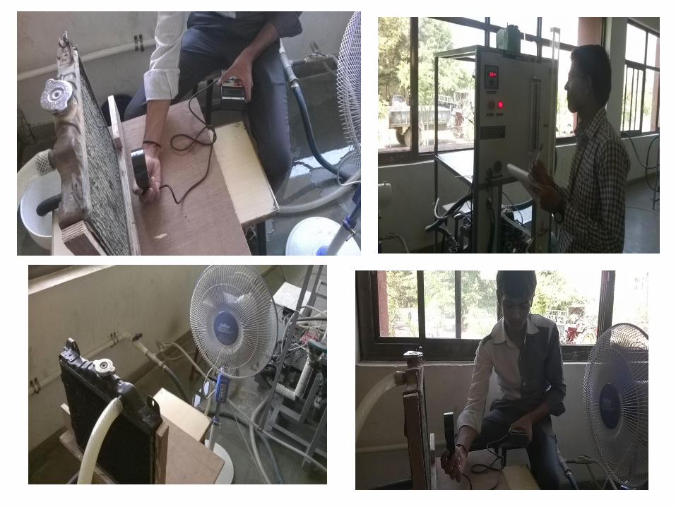
Figure 1: New radiator designed setup
System Configuration
14
EXPERIMENT

15
Figure 2: Old radiator designed setup

Hradiator
Lradiator
Wradiator
Tube Banks
Fins
Air Flow Coolant Outlet
Coolant Inlet
Figure 2: Schematic of radiator
• The coolant fluid (water) that passes through the engine block
enters on the high side of the radiator as the hot fluid. From here,
this hot fluid fills the tube banks of the radiator and makes a single
pass across the radiator.16

• Cool air is then forced across the radiator’s core, by a fan and
by using air produced by the motion of the vehicle, to absorb
and remove the heat from the coolant. During the entire
process two main forms of heat transfer occur:
• (1) convection due to the internal flow of fluid passing through
circular or non-circular tubes.
• (2) convection due to the external flow of air across the tube
bank.
Htube
Twater,in
Lradiator
Wtube
Twater,out
Figure 3: Schematic of single tube 17

SETUP
• An copper stock radiator of maruti800 will be tested with an
engine at idle conditions. The coolant used in the radiator is
pure water. The inlet and outlet temperatures for both the water
and the air will be measured using a thermocouple and multi
thermometer.
• For the water, a probe can be inserted in the tube right before
the fluid enters the radiator and right after it exits. The inlet
and outlet temperature of air will be measure with multi
thermometer.
• Inlet mass flow rate of water will be measure with Rotometer.
And inlet velocity of air can be measure with Anemometer.
18

PROCEDURE
• The engine run with predefine mass flow rate of water. Mass
flow rate set at different value by rotometer. Once the engine
reached this temperature, the fan in front of the radiator will be
turned on to begin cooling the radiator. The radiator, along
with the fan, then cooled the radiator until the temperatures
reached steady state.
• The inlet and outlet temperatures and the for air and water will
be then record. Air velocity also be record by anemometor.
• This experimental process will repeated four times in order to
give a range of results to compare with one another.
19
20
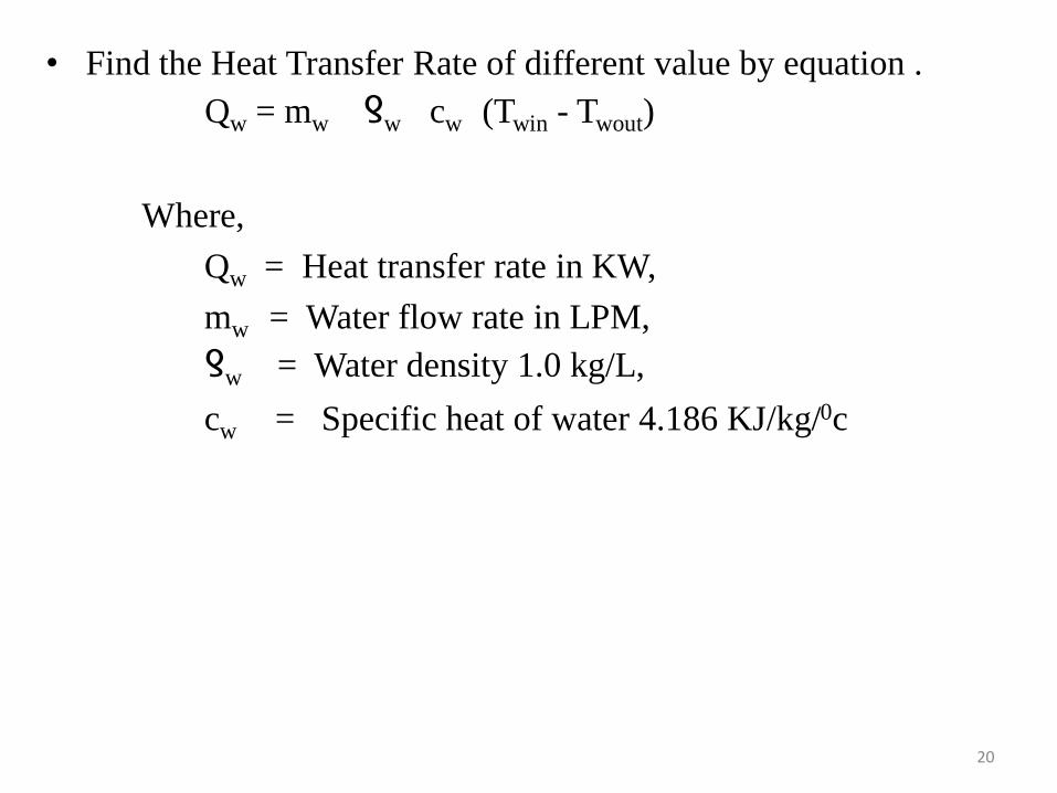
• Find the Heat Transfer Rate of different value by equation .
Qw = mw ƍw cw (Twin - Twout)
Where,
Qw = Heat transfer rate in KW,
mw = Water flow rate in LPM,
ƍw = Water density 1.0 kg/L,
cw = Specific heat of water 4.186 KJ/kg/0c

• SPECIFICATION
21
SPECIFICATION NEW RADIATOR OLD RADIATOR
MATERIAL COPPER COPPER
NO. OF TUBES 118 56
NO OF ROW OF TUBES 3 2
FIN GEOMETRY PLATE TYPE ZIG ZAG TYPE
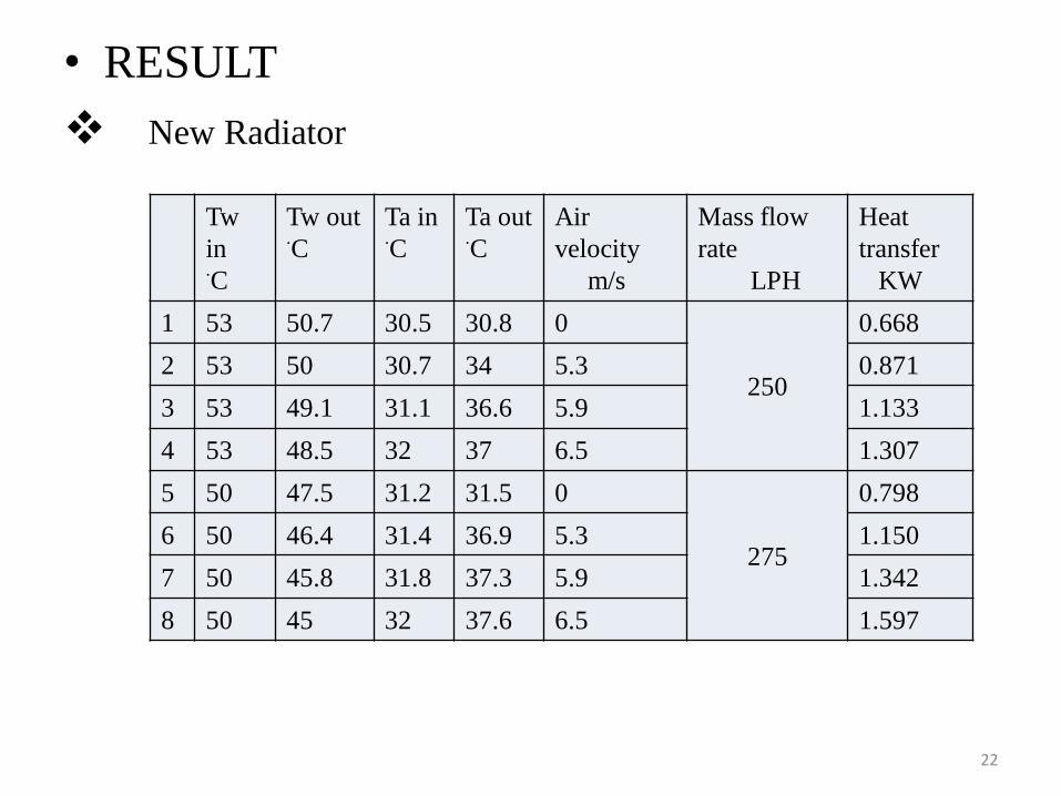
• RESULT
New Radiator
22
Tw
in .C
Tw out.C
Ta in.C
Ta out.C
Air
velocity
m/s
Mass flow
rate
LPH
Heat
transfer
KW
1 53 50.7 30.5 30.8 0
250
0.668
2 53 50 30.7 34 5.3 0.871
3 53 49.1 31.1 36.6 5.9 1.133
4 53 48.5 32 37 6.5 1.307
5 50 47.5 31.2 31.5 0
275
0.798
6 50 46.4 31.4 36.9 5.3 1.150
7 50 45.8 31.8 37.3 5.9 1.342
8 50 45 32 37.6 6.5 1.597

Tw in.C
Tw out.C
Ta in.C
Ta out.C
Air
velocity
m/s
Mass flow
rate
LPH
Heat
transfer
KW
9 46 44 32.5 33 0
500
1.162
10 46 43.6 31.9 36.7 5.3 1.395
11 46 42.7 30.5 33.5 5.9 1.918
12 46 42 29.6 31.8 6.5 2.325
13 42 40.4 32.5 33 0
1000
1.860
14 42 40 31.5 34.3 5.3 2.324
15 42 39.1 30 33.3 5.9 3.370
16 42 38.4 29 31.8 6.5 4.184
23

24
Tw
in .C
Tw out.C
Ta in.C
Ta out.C
Air
velocity
m/s
Mass flow
rate
LPH
Heat
transfer
KW
1 53 51.6 32 32.3 0
250
0.407
2 53 50.8 31.1 34 5.3 0.639
3 53 49.9 31.6 36.1 5.9 0.900
4 53 49 32.5 36.8 6.5 1.162
5 50 48 32.4 32.7 0
275
0.639
6 50 47.5 36 36.5 5.3 0.798
7 50 46.7 32.7 36.5 5.9 1.054
8 50 45.7 33.4 37.1 6.5 1.380
Old radiator

Tw
in.C
Tw out.C
Ta in.C
Ta out.C
Air
velocity
m/s
Mass flow
rate
LPH
Heat
transfer
KW
9 46 44.5 33.5 34 0
500
0.871
10 46 44 32.7 35.5 5.3 1.162
11 46 43 31.5 33 5.9 1.743
12 46 42.1 30 31.6 6.5 2.267
13 42 40.9 33.5 34.1 0
1000
1.278
14 42 40.3 31.6 33.3 5.3 1.975
15 42 39.3 30.5 33 5.9 3.138
16 42 38.8 29.8 30.8 6.5 3.720
25

• Effectiveness of new radiator
Q= 4.184 KW
Th in =42 Tc in =29
Th out=38.4 Tc out =30.6
Tc mean =
= 29.8
Cpc = 1.005 KJ/kg K
Q = m Cp ΔT
4.184 = m 1.005 1.6
m = 2.60 kg/s
26
2
296.30

Th min=
= 40.2
Cph = 4.174KJ/kgK
Q=m Cp ΔT
4.184= m 4.174 3.6
mh=0.278 kg/s
mh cph =0.278 4.174
= 1.160 KW/K
mc cpc = 2.60 1.005
= 2.613 KW/K
27
2
4.3842

28
Ɛ=
= mc cph(Th in-Th out) = 1.160(42-38.4) = 0.2761 = 27%
Cmin (Thin-Tcin) 1.160(42-29)
maxQ
Qactual

• Effectiveness of old radiator
Q = 3.720 KW
Th in = 42 Tc in =29.8
Th out= 39.8 Tc out =30.8
Tc mean =
= 30.3
Cpc = 1.005 KJ/kg K
Q = m Cp ΔT
3.720 = m 1.005 1
m = 3.70 kg/s
29
2
8.308.29

Th min=
= 40.9
Cph = 4.175KJ/kgK
Q=m Cp ΔT
3.720 = m 4.175 2.2
mh= 0.405 kg/s
mh cph = 0.405 4.175
= 1.690 KW/K
mc cpc = 3.70 1.005
= 3.7185 KW/K
30
2
8.3942

31
Ɛ=
= mc cph(Th in-Th out) = 1.160(42-39.8) = 0.180 = 18%
Cmin (Thin-Tcin) 1.160(42-29.8)
maxQ
Qactual

SOFTWARE DESIGN
32

33

34

NEW RADIATOR

76543210
51.0
50.5
50.0
49.5
49.0
48.5
Air velocity(m/ s)
Tw
ou
tlet(
0c)
250
250
250
250
MASS FLOW RATE 250LPH
NEW RADIATOR

76543210
32.00
31.75
31.50
31.25
31.00
30.75
30.50
Air velocity(m/ s)
Tair
in
let(
0c)
250
250
250
250
MASS FLOW RATE 250LPH
NEW RADIATOR
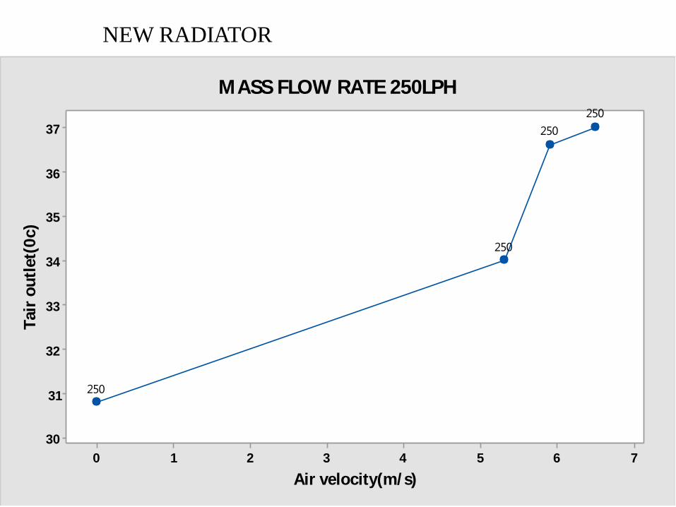
76543210
37
36
35
34
33
32
31
30
Air velocity(m/ s)
Tair
ou
tlet(
0c)
250
250
250
250
MASS FLOW RATE 250LPH
NEW RADIATOR

NEW RADIATOR

76543210
1.3
1.2
1.1
1.0
0.9
0.8
0.7
0.6
Air velocity(m/ s)
Heat
tran
sfer(
KW
)
250
250
250
250
MASS FLOW RATE 250LPH
NEW RADIATOR

NEW RADIATOR

NEW RADIATOR

NEW RADIATOR

44
NEW RADIATOR

45
NEW RADIATOR AND OLD RADIATOR

NEW RADIATOR AND OLD RADIATOR
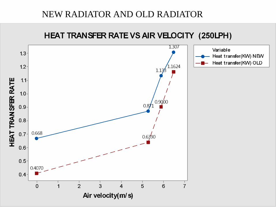
47
NEW RADIATOR AND OLD RADIATOR

48
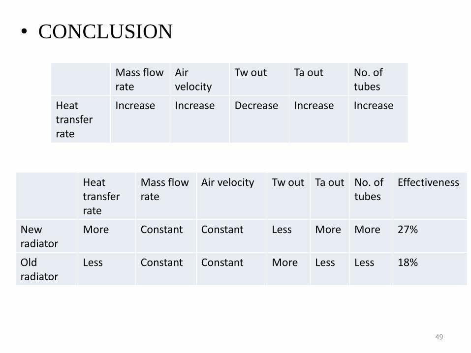
• CONCLUSION
49
Mass flow rate
Airvelocity
Tw out Ta out No. of tubes
Heat transfer rate
Increase Increase Decrease Increase Increase
Heat transfer rate
Mass flow rate
Air velocity Tw out Ta out No. of tubes
Effectiveness
New radiator
More Constant Constant Less More More 27%
Old radiator
Less Constant Constant More Less Less 18%

50
• The heat transfer processes for the radiator are analyzed in a real
life situation. The objectives of the project, to find the inlet and
outlet temperatures of the fluids in the radiator, were accomplished
successfully. There were numerous assumptions that were
necessary to complete the theoretical calculations. Although these
assumptions changed the final values for the theoretical heat
transfer rate, the differences are expected. When first analyzing the
radiator, there were many challenges and obstacles that hindered the
advancement of the project. These challenges presented with
opportunities to learn from mistakes and link concepts into an
integrated whole. This project provided an in depth understanding
of the theoretical knowledge learned in heat transfer and offered a
chance to use this information to solve real world problems.

51
• Future Work
• SOFTWARE ANALYSIS

LITERATURE SURVEY
Matthew Carl et al[1] The heat transfer processes for the radiator
are analyzed in a real life situation. The objectives of the project,
to find and compare the inlet and outlet temperatures of the fluids
in the radiator. There were numerous assumptions that were
necessary to complete the theoretical calculations. Although these
assumptions changed the final values for the theoretical outlet
temperatures and heat transfer rate, the differences are expected.
The theoretical values are good approximations of the real values
found experimentally.
52

Brandon Fell et al[2] Our task was to design a new concept for an
automotive radiator. It was required to reject an increased amount
of heat (5%) from current radiator designs while lowering the
fluid inlet temperature (10%). Our task is to design an automotive
radiator to work in conjunction with advanced nanofluids. The
new radiator design will be used in new General Motors hybrid
vehicles. These hybrid vehicles have multiple cooling systems for
the internal combustion engine, electric engine, and batteries.
Q. Yuet al[3] showed that one way to decrease the thermal
resistance associated with the air is to change the type of fin
material used. Instead of using aluminum fins, fins constructed of
carbon-foam were used. The fins were constructed out carbon-
foam that had a porosity of 70%, a thickness of 0.762 mm, and a
height of 8.725 mm. The fin density was set to 748 fins/m.
53

• Fin Dimensions and Efficiency
Figure: 6.7. Actual fin geometry
The geometry of the fins on the radiator is sinusoidal. The troughs ofthe fins touch the lower adjacent tube and the peaks of the fins touchthe upper adjacent tube. The heat from the tubes emanates through thefins. The fins and tubes are then cooled by the air from the fan, whichis traveling across the radiator. To simplify the geometry for the easeof calculations, the fins are assumed to be straight instead ofsinusoidal. This is a minor transition in geometry since the shape andposition of the actual fins are so close to the straight configuration.The following formulas are given below to calculate the finefficiency. The fin efficiency equation takes into account thegeometry of the fin and its dimensions to find the efficiency the finwill have. 54
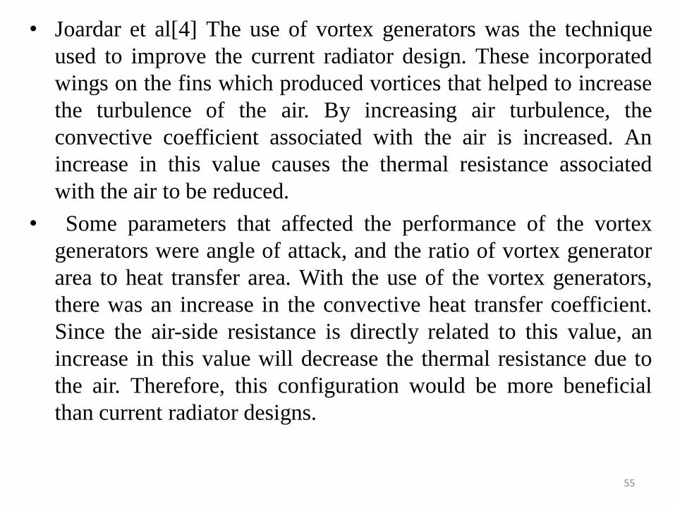
• Joardar et al[4] The use of vortex generators was the technique
used to improve the current radiator design. These incorporated
wings on the fins which produced vortices that helped to increase
the turbulence of the air. By increasing air turbulence, the
convective coefficient associated with the air is increased. An
increase in this value causes the thermal resistance associated
with the air to be reduced.
• Some parameters that affected the performance of the vortex
generators were angle of attack, and the ratio of vortex generator
area to heat transfer area. With the use of the vortex generators,
there was an increase in the convective heat transfer coefficient.
Since the air-side resistance is directly related to this value, an
increase in this value will decrease the thermal resistance due to
the air. Therefore, this configuration would be more beneficial
than current radiator designs.
55

56
Figure: 4.3. Vortex generators increase convective heat transfer

C. Harris et al[5] possible improvement to the automobile radiator
was seen through the analysis of micro heat exchangers. These heat
exchangers incorporated the use of micro-channels and were
fabricated from plastic, ceramic, or aluminum. One area was on a
heat transfer rate to volume basis in which the micro heat exchanger
was better by more than 300%. These improvements were achieved
by limiting the flow to smaller channels which increased the surface
area/volume ratio and reduced the convective thermal resistance
associated with the solid/fluid interface.
Prof. D. K. Chavan[6]The Heat Exchangers or Radiators used in
automobiles/IC Engines are either rectangular or square in shape, but
the air blown/sucked by means of the fan is in circular in area,
developing low velocity zones in the corners-hence it is proposed to
eliminate corners and develop circular radiators. The object of work
is to have a circular radiator which is compact-made with minimum
material-less costly-more efficient-that will work with minimum
power consumption of fan and maximum utilization of air flow.57

JP Yadav et al[7]In the testing, a comparative analysis between
different coolants has also been shown. Here, one of the coolants
is used as water and other as mixture of water in propylene glycol
in a ratio of 40:60. Here a big difference in the cooling capacity
of the radiator is seen when the flowing coolant from water is
changed to mixture. This is on the account of a very high value of
specific heat of water in comparison to the mixture. It therefore
can be concluded that the water is still the best coolant but its
limitation are that it is corrosive and contains dissolved salts that
degrade the coolant flow passage. By making a mixture with
ethylene glycol its specific heat is decreased but its other
properties are enhanced.
58

S. R. Patil et al[8] Automotive radiator is key component of
engine cooling system. Radiator size depends on heat load as well
packaging space availability. Heat load depends on heat rejection
required to keep engine surface at optimum temperature.
Generally LMTD or ε- NTU method is used to do heat transfer
calculations of radiator. Both methods have its own advantages
and preferred according to data availability. When radiator inlet
and outlet temperature are known LMTD gives faster solution.
When any of the temperature is unknown LMTD method
undergoes iterations to find solution. In this case ε-NTU is better.
59

Patankar and Prakash[9] presented a two dimensional anyalysis
for the flow and heat transfer in an interrupted plate passage
which is an idealization of the offset stripe fins heat
exchanger. The main aim of study is investi-gating the effect
of plate thickness on heat transfer and pressure drop in offset
strip fins channels.
60

REFERENCES
[1]Matthew Carl, Dana Guy, Brett Leyendecker, Austin
Miller,and Xuejun Fan. “THE THEORETICAL AND
EXPERIMENTAL INVESTIGATION OF THE HEAT
TRANSFER PROCESS OF AN AUTOMOBILE RADIATOR”.
2012 ASEE Gulf Southwest Annual Conference.
[2] Brandon Fell, Scott Janowiak, Alexander Kazanis , Contact
Jeffrey Martinez. “High Efficiency Radiator Design for Advanced
Coolant”. 2007
[3] Q. Yu, A.Straatman, and B. Thompson, “Carbon-Foam
Finned Tubes in Air-Water Heat Exchangers,” Applied Thermal
Engineering, 26 (2006) pp. 131-143.
61

[4] C. Harris, M. Despa, and K. Kelly, “Design and Fabrication of
a Cross Flow Micro Heat Exchanger,” Journal of
Microelectromechanical Systems, vol. 9, no. 4, pp. 502-508,
December 2004.
[5] A. Joardar and A.Jacobi, “Impact of Leading Edge Delta-
Wing Vortex Generators on the Thermal Performance of a Flat
Tube, Louvered-Fin Compact Heat Exchanger,” International
Journal of Heat and Mass Transfer, 48 (2005) pp. 1480-1493.
[6] Prof. D. K. Chavan, Prof. Dr. G. S. Tasgaonkar.”Thermal
Optimization of Fan assisted Heat Exchanger (Radiator) by
Design Improvements” International Journal of Modern
Engineering Research (IJMER) 2010, Vol.1, Issue1, pp- 225-228.
62

[7]JP Yadav and Bharat Raj Singh “Study on Performance
Evaluation of Automotive Radiator” International Journal of
Modern Engineering Research (IJMER) 2011, ISSN : 2229-7111,
Vol. 2.
[8] S. R. Patil , P. S. Amrutkar “Automotive Radiator Sizing and
Rating – Simulation Approach” IOSR Journal of Mechanical and
Civil Engineering 2005, PP : 01-05.
[9] Patankar S.V and Prakash C. 1981 An Analysis of Plate
Thickness on Laminar flow and Heat transfer in interrupted Plate
passages. International Journal of Heat and Mass transfer
24:1801-1810.
63

64

65
66

‹#›