to: parties interested in cast-in insert assemblies …subject: proposed revisions to the acceptance...
TRANSCRIPT

April 14, 2020 TO: PARTIES INTERESTED IN CAST-IN INSERT ASSEMBLIES IN CONCRETE SUBJECT: Proposed Revisions to the Acceptance Criteria for Cast-In Insert Assemblies in
Concrete, Subject AC502-0620-R1 (VC/HS).
Hearing Information: WebEx Event Meetings Tuesday, June 2, 2020 Wednesday, June 3, 2020 8:00 am Pacific Daylight Time Click each date above to register. Please register for both days.
Dear Colleague: You are invited to comment on proposed revisions to AC502, which will be discussed at the Evaluation Committee hearing noted above. The proposed revisions are requested by a report holder, prepared by ICC-ES Staff, to add recognition for oblique tension for use in cracked concrete for Seismic Design Categories A through F. The revisions to AC502 are be summarized as follows: 1. Addition of optional testing and evaluation requirements of cast-in insert assemblies for
oblique tension forces applied to the insert assemblies with insert wire attachment elements for splayed wire installations.
2. Addition of Figure 3 for cast-in insert assemblies with wire attachment elements.
3. Minor editorial changes to the criteria to improve clarity.
4. Correction to Table 2, footnote for Ns, such that the maximum tension test load shall be 0.5 times instead of 1.5 times the reference capacity for consistency with Acceptance Criteria for Mechanical Anchors in Concrete Elements AC193, Section 9.5.2 for strength design.
Should the committee approve the proposed revisions to the criteria, the ICC-ES staff will not recommend a compliance date. Compliance with the revised criteria will therefore be at the option of existing report holders, when they seek recognition for the optional tests to the proposed changes listed above.

AC502-0620-R1
2
You are invited to submit written comments on this or any other agenda item, or to attend the Evaluation Committee hearing and present your views in person. If you wish to contribute to the discussion, please note the following: 1. Regarding written comments and presentations:
a. You should submit these via e-mail to [email protected] or by U.S. mail to the Western
Regional (Brea) office to be received by the applicable due date.
b. Comments are to be received by May 05, 2020. These written comments will be forwarded to the committee before the meeting, and will also be posted on the ICC-ES web site shortly after the deadline for submission. Written comments that are not submitted by this deadline will not be considered at the meeting.
c. Rebuttal comments, from the proponent noted in this letter, are to be received by May 15, 2020. They will be forwarded to the committee before the meeting, and will also be posted on the ICC-ES web site shortly after the deadline for submission. Written rebuttal comments that are not submitted by the deadline will not be considered at the meeting.
d. Visual presentations, in PowerPoint format only, are to be received by May 15, 2020. These will be forwarded to the committee before the meeting, and will also be posted on the ICC-ES web site shortly after the deadline for submission. Presentations that are not submitted by the deadline cannot be viewed at the meeting. Note: Videos will not be posted on the web site.
Presentations will be retained with other records of the meeting. It is the presenter’s responsibility, prior to the presentation, to verify with ICC-ES staff that the presentation files have been transferred satisfactorily to the presentation computer.
e. ICC-ES will post to the web site, on May 29, 2020, memos by the ICC-ES staff, responding to the previously received public comments.
f. If you miss the deadlines for submission of written comments and visual presentations, your verbal comments can be presented at the meeting.
g. Proposed criteria, written public comments, visual presentations, and responses by ICC-ES staff for this agenda item are all available on our website.
2. Regarding verbal comments and presentations:
Please plan to speak for not more than ten minutes. As noted above, visuals must be in PowerPoint format. We have a computer, projector, and screen available to those making visual presentations. It is the presenter’s responsibility, prior to their presentation, to verify with ICC-ES staff that presentation files have been satisfactorily transferred to the presentation computer.

AC502-0620-R1
3
3. Keep in mind that all materials submitted for committee consideration are part of the public record and will not be treated as confidential. It is the presenter’s responsibility to certify to ICC-ES staff that no materials infringe copyright.
4. Please do not communicate with committee members before the meeting about any items
on the agenda. We appreciate your interest in the work of the Evaluation Committee. If you have any questions, please contact me at (800) 423-6587, extension 3288, or Howard Silverman, P.E. at extension 3996. You may also reach us by e-mail at [email protected].
Yours very truly,
Vincent Chui, P.E., S.E. Regional Engineering Director
VC:HS/raf Encl. cc: Evaluation Committee
October 2018 (Header revised December 3, 2019) Page 1 of 3
www.icc-es.org | (800) 423-6587 | (562) 699-0543 A Subsidiary of the International Code Council ®
ICC EVALUATION SERVICE, LLC,
RULES OF PROCEDURE FOR THE EVALUATION COMMITTEE
1.0 PURPOSE The purpose of the Evaluation Committee is to monitor the work of ICC-ES, in issuing evaluation reports; to evaluate and approve acceptance criteria on which evaluation reports may be based; and to sponsor related changes in the applicable codes.
2.0 MEMBERSHIP 2.1 The Evaluation Committee has a membership of
not fewer than nine, with one of the members named by the ICC-ES president each year to serve as the chairman–moderator.
2.2 All members of the committee shall be representatives of a body enforcing regulations related to the built environment.
2.3 Persons are appointed to the committee by the ICC-ES president, from among individuals who have formally applied for membership.
2.4 The ICC-ES Board of Managers, using simple majority vote, shall ratify the nominations of the president.
2.5 Committee membership is for one year, coinciding with the calendar year. Members may be renominated and reappointed, but no person shall serve for more than five consecutive terms.
2.6 In the event that a member is unable to attend a committee meeting or complete a term on the committee, the ICC-ES president may appoint a replacement to fill in at the meeting or for the remainder of the member’s term. Any replacement appointed for only one meeting must have prior experience as a member of the Evaluation Committee. Appointments under this section (Section 2.6) are subject to ratification as noted in Section 2.4. 3.0 MEETINGS
3.1 The Evaluation Committee shall schedule meetings that are open to the public in discharging its duties under Section 1.0, subject to Section 3.0.
3.2 All scheduled meetings shall be publicly announced. There shall be three in-person meetings per year.
3.3 More than half of the Evaluation Committee members, counting the chairman, shall constitute a quorum. A majority vote of members present is required on any action. To avoid any tie vote, the chairman may choose to exercise or not exercise, as necessary, his or her right to vote.
3.4 In the absence of the chairman–moderator, Evaluation Committee members present shall elect an alternate chairman from the committee for that meeting. The alternate chairman shall be counted as a voting committee member for purposes of maintaining a
committee quorum and to cast a tie-breaking vote of the committee.
3.5 Minutes shall be kept and shall be the official record of each meeting, including meetings by conference call.
3.6 An electronic record of meetings may be made by ICC-ES if deemed necessary; no other audio, video, electronic or stenographic recordings of the meetings will be permitted. Visual aids (including, but not limited to, charts, overhead transparencies, slides, videos, or presentation software) viewed at meetings shall be permitted only if the presenter provides ICC-ES before the presentation with a copy of the visual aid in a medium which can be retained by ICC-ES with its record of the meeting and which can also be provided to interested parties requesting a copy.
3.7 Parties interested in the deliberations of the committee should refrain from communicating, whether in writing or verbally, with committee members regarding agenda items. All written communications and submissions regarding agenda items must be delivered to ICC-ES and shall be considered nonconfidential and available for discussion in open session of an Evaluation Committee meeting. Such materials will be posted on the ICC-ES web site (www.icc-es.org) prior to the meeting. Comments and submissions not meeting the following deadlines will not be considered at the meeting:
Initial comments on agenda items shall be submitted at least 28 days before the scheduled meeting.
A rebuttal comment period shall follow, whereby rebuttal comments to the initial comments may be submitted by the proponent at least 21 days before the scheduled meeting.
Those planning on giving a visual presentation at the meeting must submit their presentation, in PowerPoint format only, at least 10 days before the scheduled meeting.
The committee reserves the right to refuse recognition of communications which do not comply with the provisions of this section.
4.0 CLOSED SESSIONS Evaluation Committee meetings shall be open except that at the discretion of the chairman, staff counsel may be necessary. Also, matters related to clients or potential clients covered by confidentiality requirements of ICC-ES Rules of Procedure for Evaluation Reports are discussed only during closed meetings.
5.0 ACCEPTANCE CRITERIA
5.1 Acceptance criteria are established by the committee to provide a basis for issuing ICC-ES evaluation reports on products and systems under codes referenced in Section 2.0 of the Rules of Procedure for Evaluation
ICC EVALUATION SERVICE, LLC, RULES OF PROCEDURE FOR THE EVALUATION COMMITTEE
October 2018 (Header revised December 3, 2019) Page 2 of 3
Reports. They also clarify conditions of acceptance for products and systems specifically regulated by the codes.
Acceptance criteria may involve a product, material, method of construction, or service. Consideration of any acceptance criteria must be in conjunction with a current and valid application for an ICC-ES evaluation report, an existing ICC-ES evaluation report, or as otherwise determined by the Evaluation Committee.
EXCEPTIONS: The following acceptance criteria are controlled by the ICC-ES executive staff and are not subject to committee approval:
The Acceptance Criteria for Quality Documentation (AC10)
The Acceptance Criteria for Test Reports (AC85)
The Acceptance Criteria for Inspections and Inspection Agencies (AC304)
5.2 Procedure: 5.2.1 Proposed acceptance criteria shall be
developed by the ICC-ES staff and discussed in open session with the Evaluation Committee during a scheduled meeting, except as permitted in Section 4.0 of these rules.
5.2.2 Proposed acceptance criteria shall be available to interested parties at least 30 days before discussion at the committee meeting.
5.2.3 The committee shall be informed of all pertinent written communications received by ICC-ES.
5.2.4 Attendees at Evaluation Committee meetings shall have the opportunity to speak on acceptance criteria listed on the meeting agenda, to provide information to committee members. In the interest of fairness, each person requesting to testify on a proposed acceptance criteria or proposed changes to an existing acceptance criteria will be given the same amount of time. The following time limits are established:
a. For entities offering their first testimony on any item, a 10-minute limit applies. This time limit applies to both verbal testimony and/or visual presentations.
b. Each person offering testimony may return to the microphone for one five-minute period to offer additional testimony and/or to rebut testimony given by others.
c. Each person offering testimony on the staff recommendation, on each criteria, is allowed one, two-minute trip to the microphone.
Time limits do not include time needed to answer questions from the staff and/or committee members. The chairman–moderator shall have limited authority to modify time limitations on testimony. The chairman–moderator shall also have the authority to adjust time limits as necessary in order to get through the hearing agenda.
Keeping of time for testimony by an individual will be by an automatic timing device. The time remaining shall be evident to the person testifying. Interruptions during testimony will not be tolerated. It is the responsibility of the chairman–moderator to maintain decorum and order during all testimony.
5.3 Approval of any action on an acceptance criteria shall be as specified in Section 3.3 of these rules. Possible actions made by the Evaluation Committee include:
Approval; Approval with Revisions; Disapproval; or Further Study. The Evaluation Committee must give the reason(s) for any Disapproval or Further Study actions.
5.4 Actions of the Evaluation Committee may be appealed in accordance with the ICC-ES Rules of Procedure for Appeal of Acceptance Criteria or the ICC-ES Rules of Procedure for Appeals of Evaluation Committee Technical Decisions.
6.0 COMMITTEE BALLOTING FOR ACCEPTANCE CRITERIA
6.1 Acceptance criteria may be issued without a public hearing following a 30-day public comment period and a majority vote for approval by the Evaluation Committee when, in the opinion of ICC-ES staff, one or more of the following conditions have been met:
1. The subject is nonstructural, does not involve life safety, and is addressed in nationally recognized standards or generally accepted industry standards.
2. The subject is a revision to an existing acceptance criteria that requires a formal action by the Evaluation Committee.
3. Other acceptance criteria and/or the code provide precedence for the revised criteria.
6.2 Negative votes must be based upon one or more of the following, for the ballots to be considered valid and require resolution:
a. Lack of clarity: There is insufficient explanation of the scope of the acceptance criteria or insufficient description of the intended use of the product or system; or the acceptance criteria is so unclear as to be unacceptable. (The areas where greater clarity is required must be specifically identified.)
b. Insufficiency: The criteria is insufficient for proper evaluation of the product or system. (The provisions of the criteria that are in question must be specifically identified.)
c. The subject of the acceptance criteria is not within the scope of the applicable codes: A report issued by ICC-ES is intended to provide a basis for approval under the codes. If the subject of the acceptance criteria is not regulated by the codes, there is no basis for issuing a report, or a criteria. (Specifics must be provided concerning the inapplicability of the code.)
d. The subject of the acceptance criteria needs to be discussed in public hearings. The committee member requests additional input from other committee members, staff or industry.
6.3 An Evaluation Committee member, in voting on an acceptance criteria, may only cast the following ballots:
• Approved
• Approved with Comments
• Negative: Do Not Proceed 7.0 COMMITTEE COMMUNICATION Direct communication between committee members, and between committee members and an applicant or concerned party, with regard to the processing of a
ICC EVALUATION SERVICE, LLC, RULES OF PROCEDURE FOR THE EVALUATION COMMITTEE
October 2018 (Header revised December 3, 2019) Page 3 of 3
particular acceptance criteria or evaluation report, shall take place only in a public hearing of the Evaluation Committee. Accordingly:
7.1 Committee members receiving an electronic ballot should respond only to the sender (ICC-ES staff). Committee members who wish to discuss a particular matter with other committee members, before reaching a decision, should ballot accordingly and bring the matter to the attention of ICC-ES staff, so the issue can be placed on the agenda of a future committee meeting.
7.2 Committee members who are contacted by an applicant or concerned party on a particular matter that will
be brought to the committee will refrain from private communication and will encourage the applicant or concerned party to forward their concerns through the ICC-ES staff in writing, and/or make their concerns known by addressing the committee at a public hearing, so that their concerns can receive the attention of all committee members.■
Revised October 2018

www.icc-es.org | (800) 423-6587 | (562) 699-0543 A Subsidiary of the International Code Council ®
PROPOSED REVISIONS TO THE ACCEPTANCE CRITERIA FOR CAST-IN INSERT ASSEMBLIES IN CONCRETE
AC502
Proposed April 2020
Previously approved June 2018
PREFACE
Evaluation reports issued by ICC Evaluation Service, LLC (ICC-ES), are based upon performance features of the International family of codes. (Some reports may also reference older code families such as the BOCA National Codes, the Standard Codes, and the Uniform Codes.) Section 104.11 of the International Building Code® reads as follows:
The provisions of this code are not intended to prevent the installation of any materials or to prohibit any design or method of construction not specifically prescribed by this code, provided that any such alternative has been approved. An alternative material, design or method of construction shall be approved where the building official finds that the proposed design is satisfactory and complies with the intent of the provisions of this code, and that the material, method or work offered is, for the purpose intended, at least the equivalent of that prescribed in this code in quality, strength, effectiveness, fire resistance, durability and safety.
ICC-ES may consider alternate criteria for report approval, provided the report applicant submits data demonstrating that the alternate criteria are at least equivalent to the criteria set forth in this document, and otherwise demonstrate compliance with the performance features of the codes. ICC-ES retains the right to refuse to issue or renew any evaluation report, if the applicable product, material, or method of construction is such that either unusual care with its installation or use must be exercised for satisfactory performance, or if malfunctioning is apt to cause injury or unreasonable damage.
Acceptance criteria are developed for use solely by ICC-ES for purposes of issuing ICC-ES evaluation reports.
ICC EVALUATION SERVICE® and ICC-ES® (and their associated logos) are registered trademarks and service marks of ICC Evaluation Service, LLC, and INTERNATIONAL CODE COUNCIL®, ICC®, INTERNATIONAL BUILDING CODE® and IBC® (and their associated logos)
are registered trademarks and service marks of its parent company, International Code Council, Inc.
No portion of this document (AC502) may be copied, reproduced, reprinted, republished, distributed, transmitted, or modified in any form or manner without the express prior written permission of ICC-ES. Any request for such permission should be addressed to ICC-ES at 3060
Saturn Street, Suite 100, Brea, California 92821. Any of the foregoing expressly authorized by ICC-ES must include all the copyright, trademark, service mark and other proprietary rights notices contained herein.
Copyright © 2020 ICC Evaluation Service, LLC. All rights reserved.

Page 2 of 9
PROPOSED REVISIONS TO THE ACCEPTANCE CRITERIA FOR CAST-IN INSERT ASSEMBLIES IN CONCRETE (AC502)
1.0 INTRODUCTION
1.1 Purpose: The purpose of this acceptance criteria is to establish requirements for cast-in insert assemblies in concrete to be recognized in an ICC Evaluation Service, LLC (ICC-ES), evaluation report under the 2018, 2015 and 2012 International Building Code® (IBC), and the 2018, 2015 and 2012 International Residential Code® (IRC). Basis of recognition are IBC Sections 104.11 and 1901.3, and IRC Section R104.11.
1.2 Scope: The scope of this criteria addresses cast-in insert assemblies used to attach architectural, mechanical, electrical and similar systems to the building structure that are not part of the primary load bearing or lateral-force resisting systems of the structure (i.e. non-structural components) installed in normal-weight concrete, and normal-weight or sand-lightweight concrete filled metal deck. The cast-in insert assemblies evaluated under this criteria shall rely on bearing and/or composite action with the concrete for purposes of transmitting vertical downward tension loads only , and oblique tension loads applied to the cast-in insert assemblies and transferred into the concrete member. The provisions of this criteria shall be applicable only to cast-in insert assemblies as defined in Section 1.4 of this criteria.
1.3 Codes and Referenced Standards: 1.3.1 2018, 2015 and 2012 International Building
Code® (IBC), International Code Council. 1.3.2 2018, 2015 and 2012 International Residential
Code® (IRC), International Code Council. 1.3.3 ACI 211.1-91 (2009), Standard Practice for
Selecting Proportions for Normal, Heavyweight and Mass Concrete, American Concrete Institute.
1.3.4 ACI 211.2-98 (2004), Standard Practice for Selecting Proportions for Structural Lightweight Concrete, American Concrete Institute.
1.3.5 ACI 213R-03, Guide for Structural Lightweight Aggregate Concrete.
1.3.6 ACI-318 (-14 and -11), Building Code Requirements for Structural Concrete, American Concrete Institute.
1.3.7 ACI 355.2-07, Qualification of Post-Installed Mechanical Anchors in Concrete, American Concrete Institute.
1.3.8 ANSI B18.2.1-96 Square and Hex Bolts and Screws – Inch Series.
1.3.9 ASTM C31 (-12 and -09), Standard Practice for Making and Curing Concrete Test Specimens in the Field, ASTM International.
1.3.10 ASTM C33 (-13 and -08), Standard Specification for Concrete Aggregates, ASTM International.
1.3.11 ASTM C39 (-14a and 09a), Standard Test Method for Compressive Strength of Cylindrical Concrete Specimens, ASTM International.
1.3.12 ASTM C42 (-13 and -04), Standard Test Method for Obtaining and Testing Drilled Cores and Sawed Beams of Concrete, ASTM International.
1.3.13 ASTM C150 (-12 and -09), Standard Specification for Portland Cement, ASTM International.
1.3.14 ASTM C330 (-14 and -09), Standard Specification for Lightweight Aggregates for Structural Concrete, ASTM International.
1.3.15 ASTM A370-17, Standard Test Methods and Definitions for Mechanical Testing of Steel Products, ASTM International.
1.3.16 ASTM E4-16, Standard Practices for Force Verification of Testing Machines, ASTM International.
1.3.17 ASTM E488-15, Standard Test Methods for Strength of Anchors in Concrete Elements, ASTM International.
1.3.18 ASTM F606-16, Standard Test Methods for Determining the Mechanical Properties of Externally and Internally Threaded Fasteners, Washers, Direct Tension Indicators, and Rivets, ASTM International.
1.4 Definitions: 1.4.1 Cast-in Insert Assemblies: The cast-in insert
assemblies consist of an insert receiver and insert element. See Figure 2 for vertical tension applications, and Figure 3 for oblique tension applications.
1.4.2 Low-Strength and High-Strength Concrete: Concrete within two nominal compressive strength ranges. The compressive strength of the cylinders tested in accordance with ASTM C31 and ASTM C39 shall be within these ranges:
Low-strength concrete: 2,500 to 4,000 psi (17 to 28 MPa);
High-strength concrete: 6,500 to 8,500 psi (45 to 60 MPa).
1.4.3 Insert Receiver: The insert installed in the formwork or metal deck prior to concrete placement and designed to receive an insert element. See Figure 2.
1.4.4 Insert Element: The insert element, which includes all evaluated components provided by the manufacturer, is jobsite attached into the insert receiver from below (e.g., underside of concrete slab or soffit of concrete filled metal deck) for suspending non-structural component attachments, see Section 3.2.3.2 for further description. See Figure 2 for vertical tension applications, and Figure 3 for oblique tension applications.
2.0 BASIC INFORMATION
2.1 General: The following information shall be submitted:
2.1.1 Product Description: Complete information pertaining to the cast-in insert assemblies, including material specifications, drawn-to-scale production drawings showing all dimensions and tolerances, description of the manufacturing process (including welds when applicable). Materials shall comply with recognized standards where applicable.
2.1.2 Manufacturer’s Printed Installation Instructions (MPII): Published instructions for installation of cast-in insert assemblies under all covered installation

PROPOSED REVISIONS TO THE ACCEPTANCE CRITERIA FOR CAST-IN INSERT ASSEMBLIES IN CONCRETE (AC502)
Page 3 of 9
conditions, as supplied with product packaging by the manufacturer of the cast-in insert assemblies.
2.1.3 Packaging and Identification: A description of the method of packaging and field identification of the cast-in insert assemblies. The insert receiver and insert elements of the cast-in insert assemblies shall bear an imprint that clearly identifies the manufacturer name (a registered trademark may serve as such identity) and model. Labeling of the packaging of both the insert receivers and insert elements shall include the manufacturer name, model and the ICC-ES evaluation report number.
2.1.4 Field Preparation: Information concerning methods of preparing the cast-in insert, formwork, and concrete for installation shall be described.
2.1.5 Qualification Test Plan: A qualification test plan shall be submitted to and approved by ICC-ES staff prior to any testing being conducted.
2.2 Testing Laboratories: Testing laboratories shall comply with Section 2.0 of the ICC-ES Acceptance Criteria for Test Reports (AC85) and Section 4.2 of the ICC-ES Rules of Procedure for Evaluation Reports.
2.3 Test Reports: Test reports shall comply with AC85 and include the following information:
2.3.1 Identification of the test standard used and the date of issue of the standard, and other relevant information concerning the test procedure, justification for any deviations from the referenced test standard, and any critical information relevant to the specific test.
2.3.2 A description of the sample size of randomly selected cast-in insert assemblies for each test protocol.
2.3.3 Production drawings of the tested cast-in insert assemblies, providing dimensions and identifying steel specifications.
2.3.4 Photographs of the test setup and typical failure modes shall be included in the test report.
2.3.5 Location of displacement instrumentation and their point of reference as well as load-versus-deformation curves, as plotted directly, or as reprinted from data acquisition systems.
2.3.6 Individual and average ultimate test load values with standard deviation and a description of the general behavior of tested cast-in insert assemblies during load application; and a description of the nature, type and location of failures of tested cast-in insert assemblies.
2.3.7 Description of the test setup and the cyclic protocol when cyclic testing is performed in accordance with Section 3.5 of this criteria.
2.3.8 Strength of concrete and metal deck test specimens, as applicable.
2.4 Product Sampling: Sampling shall comply with Section 3.1 of AC85.
3.0 TEST AND PERFORMANCE REQUIREMENTS
3.1 Testing Program: Testing requirements shall be in accordance with Table 1.
3.2 Test Materials:
3.2.1 Concrete: The concrete used in the cast-in insert assembly tests of Section 3.4 and 3.5 shall comply with ASTM E488 and ACI 355.2 Section 5.1.
3.2.1.1 Concrete mix design shall follow recommendations for proportioning in ACI 211.1, ACI 211.2, ACI 213R, or ACI 318, as applicable. Proportions may be varied to meet local requirements and to achieve desired nominal compressive strength. The reason for any variation shall be described in the test report. No cementitious additives shall be added to the concrete test members.
3.2.2 Concrete Compressive Strength Determination:
3.2.2.1 Concrete compressive strengths at time of tests shall comply with the ranges specified in Section 1.4.2 of this criteria and Section 5.1.3 of ACI 355.2.
3.2.2.2 Test members shall be cured a minimum of 21 days prior to the beginning of tests in accordance with Section A3.3 of ACI 355.2.
Exception: For tests to determine performance in high-early-strength or uncured concrete, a lesser curing period may be used.
3.2.2.3 Where high-early-strength concrete is used, curing shall be for a minimum of seven days, with a two-day allowable minus tolerance. Two cylinders shall be tested in accordance with ASTM C39 to determine compressive strength. The average compressive strength shall be determined within a 12-hour period immediately preceding or following any test series.
3.2.2.4 For concrete less than 90 days old, two tests of two cylinders, or cores, each prepared according to Section 3.2.1, shall be performed at the beginning and ending of testing of the cast-in insert assemblies in accordance with Table 1. The beginning of the test shall be concurrent with the initiation of testing. The beginning and ending strength results shall be averaged (four cylinders or cores, total) to establish the strength of the test members during the cast-in insert assembly test period.
3.2.2.5 For concrete aged 90 days or more, the compressive strength test shall be a single test of three cylinders or cores, performed within 30 days of any cast-in insert assembly testing.
3.2.2.6 Reported concrete compressive strength for any test series shall be determined from tests in this section, within the time limitations shown in Table 3. It shall be permitted to develop a strength vs. age relationship in accordance with ACI 355.2 A.3.3.1 for this purpose.
3.2.3 Steel Parts of Cast-in Insert Assemblies: 3.2.3.1 Insert Receiver: Provide material
properties for the insert receiver steel components. For other materials, see Section 3.2.3.3.
3.2.3.2 Insert Elements: 3.2.3.2.1 Insert elements with threaded rods
shall comply with ANSI/ASME Standard B18.2.1 or a recognized national standard. Determine steel tensile strength in accordance with ASTM F606 (see Table 1, Test No. 1 of this criteria). All steel properties of the insert element components threaded rod, including tensile strength and measured diameter shall be determined. This data is permitted to be obtained from the mill certification of

PROPOSED REVISIONS TO THE ACCEPTANCE CRITERIA FOR CAST-IN INSERT ASSEMBLIES IN CONCRETE (AC502)
Page 4 of 9
the steel from which the insert is manufactured. For other materials, see Section 3.2.3.3.
3.2.3.2.2 Insert elements with wires shall comply with ASTM A1023 or a recognized national standard. Determine wire tensile strength and the strength of the connection between the wire and threaded rod or and any other insert components in accordance with Table 1, Test No. 2 as described in Section 3.2.4. All steel properties of the wire, wire connector, adaptor clip and any other components, including tensile strength and measured gage size and the strength of connection between components shall be determined. For other materials, see Section 3.2.3.3.
3.2.3.2.3 The strength of additional components of the insert elements, and the strength of the connection between the insert element and wire or threaded rod shall be determined in accordance with Table 1, Test No. 2 as described in Section 3.2.4.
3.2.3.3 Other Materials: Where other materials (e.g., plastic) are used in the manufacture of the insert components, these shall be described in accordance with applicable standards.
3.2.4 Tension Strength of the Insert Assemblies (Table 1, Test No. 2): Perform static tension tests on the insert assemblies in a jig in accordance with Section 4.1 to determine the tension strength and failure mode of the insert assembly such as the connection of the insert element to the insert receiver and support element, and all connection components of the insert element. Each insert assembly configuration shall be tested. The length of insert element engagement into the insert receiver shall correspond to the minimum specified in the MPII.
3.2.5 Optional Oblique Tension Tests of the Insert Assemblies (Table 1, Test No. 2): For evaluation of insert assemblies with wire insert elements for use in oblique tension installations of wires, perform tension tests of the insert assemblies in a jig by rotating the insert receiver to the maximum intended angle from vertical plane (not to exceed 60 degrees) as illustrated in Figure 3 and in accordance with Section 4.1 to determine the oblique tension strength and failure mode of the insert assembly such as the adaptor clip and connection of the wire insert element to the insert receiver and support element, and all connection components of the wire insert element. Both the X-X and Y-Y axis of the insert receiver orientation shall be tested for non-symmetrical insert receivers as illustrated in Figure 3. The length of insert element engagement into the insert receiver shall correspond to the minimum specified engagement in accordance with the MPII.
3.3 Test Members: 3.3.1 General: Concrete test members shall be
prepared in accordance with Section 6.2 and 6.3 of ASTM E488 and Appendix A3 of ACI 355.2.
3.3.2 Concrete-filled Metal Deck: Concrete and metal deck of concrete filled metal deck test specimens shall be prepared as follows:
3.3.2.1 Concrete fill on metal decking specimens shall represent the minimum concrete fill thickness, maximum decking depth, minimum flute width and minimum decking thickness and decking strength for this application. Results of tests conducted in structural light-weight concrete fill shall be permitted to be used for
applications in normal-weight concrete fill. Metal decks used in all tests shall be evaluated by material property tests to determine the tensile strength, yield strength, and elongation in accordance with the appropriate standard for the metal grade. In addition, the base-metal thickness shall be determined, exclusive of coatings. Test results shall be based on the evaluation of three specimens in each thickness. Where measured properties vary from specified values, the influence of the variations on cast-in insert assembly tests shall be considered in the analysis.
3.3.2.2 Reinforcement may only be used to stabilize cast concrete test members during transportation or as required in Sections A3.1.2 and A3.2 of ACI 355.2. Reinforcing elements in concrete test members shall be outside the potential failure region of each test specimen or insert group. The test laboratory shall verify the location of the reinforcing.
3.4 Cast-in Insert Assembly Strength, Static Tension in Concrete: Perform tension tests in the minimum member depth sought for recognition to determine insert receiver tension strength in concrete in accordance with ASTM E488 (see Table 1, Test No. 3 and 4 of this criteria), and soffit of concrete filled metal deck, see Table 1, Test No. 5 of this criteria. The results of tests shall be applicable to the specific geometry, insert location, and material parameters tested. For internally threaded insert receivers, the insert element installed into the insert receiver in the concrete and concrete filled metal deck testing shall be Grade 5 or higher bolts or ASTM A193 Grade B7 threaded rods (or equivalent) in order to determine the capacity of the insert receiver in concrete and prevent insert element failure during the tests. Where steel failure of the insert element is observed during the tests, the nominal strength shall be reduced to account for overstrength of the insert element where applicable.
3.5 Optional Static Oblique Tension Tests in Concrete: For evaluation of insert assemblies with wire insert elements for use in oblique tension installations of wires, perform oblique tension tests at the maximum intended angle from the vertical plane (not to exceed 60 degrees) as illustrated in Figure 3 and in accordance with ASTM E488 (see Table 1, Test No. 3 and 4 of this criteria), and soffit of concrete over metal deck, see Table 1, Test No. 5 of this criteria. Test the insert receiver axis with the highest oblique tension strength and wire strength configuration in accordance with Section 3.2.5 test results.
3.6 3.5 Optional Simulated Seismic Tension Tests (Table 1, Tests No. 6 and 7):
3.6.1 3.5.1 Purpose: For recognition of cast-in insert assemblies for use in Seismic Design Category C, D, E or F, perform simulated seismic tension tests and oblique tension tests in accordance with Table 1, Test series 6 and 7 of this criteria, as applicable. The seismic load value for which recognition is sought desired shall be no larger than 100 percent of the static load in accordance with Section 3.64 for tension and Section 3.5 for oblique tension.
3.6.2 3.5.2 Test Conditions: 3.6.2.1 3.5.2.1 The cast-in insert assemblies shall
be subjected to a simulated pulsating sinusoidal seismic cycle, detailed in Figure 1 and Table 2, for tension. The frequency of the loading shall be within the range of 0.1 to 2 Hz.
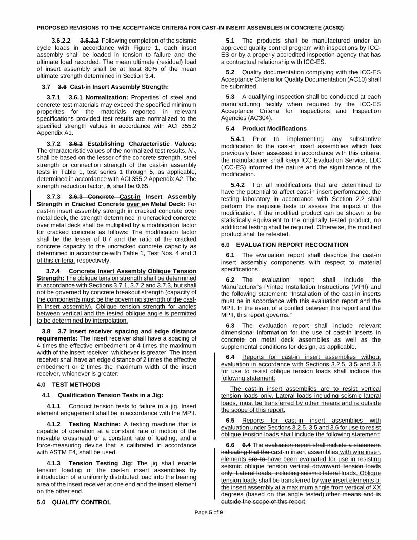
PROPOSED REVISIONS TO THE ACCEPTANCE CRITERIA FOR CAST-IN INSERT ASSEMBLIES IN CONCRETE (AC502)
Page 5 of 9
3.6.2.2 3.5.2.2 Following completion of the seismic cycle loads in accordance with Figure 1, each insert assembly shall be loaded in tension to failure and the ultimate load recorded. The mean ultimate (residual) load of insert assembly shall be at least 80% of the mean ultimate strength determined in Section 3.4.
3.7 3.6 Cast-in Insert Assembly Strength: 3.7.1 3.6.1 Normalization: Properties of steel and
concrete test materials may exceed the specified minimum properites for the materials reported in relevant specifications provided test results are normalized to the specified strength values in accordance with ACI 355.2 Appendix A1.
3.7.2 3.6.2 Establishing Characteristic Values: The characteristic values of the normalized test results, Nn, shall be based on the lesser of the concrete strength, steel strength or connection strength of the cast-in assembly tests in Table 1, test series 1 through 5, as applicable, determined in accordance with ACI 355.2 Appendix A2. The strength reduction factor, ɸ, shall be 0.65.
3.7.3 3.6.3 Concrete Cast-in Insert Assembly Strength in Cracked Concrete over on Metal Deck: For cast-in insert assembly strength in cracked concrete over metal deck, the strength determined in uncracked concrete over metal deck shall be multiplied by a modification factor for cracked concrete as follows: The modification factor shall be the lesser of 0.7 and the ratio of the cracked concrete capacity to the uncracked concrete capacity as determined in accordance with Table 1, Test Nos. 4 and 3 of this criteria, respectively.
3.7.4 Concrete Insert Assembly Oblique Tension Strength: The oblique tension strength shall be determined in accordance with Sections 3.7.1, 3.7.2 and 3.7.3, but shall not be governed by concrete breakout strength (capacity of the components must be the governing strength of the cast-in insert assembly). Oblique tension strength for angles between vertical and the tested oblique angle is permitted to be determined by interpolation.
3.8 3.7 Insert receiver spacing and edge distance requirements: The insert receiver shall have a spacing of 4 times the effective embedment or 4 times the maximum width of the insert receiver, whichever is greater. The insert receiver shall have an edge distance of 2 times the effective embedment or 2 times the maximum width of the insert receiver, whichever is greater. 4.0 TEST METHODS
4.1 Qualification Tension Tests in a Jig: 4.1.1 Conduct tension tests to failure in a jig. Insert
element engagement shall be in accordance with the MPII.
4.1.2 Testing Machine: A testing machine that is capable of operation at a constant rate of motion of the movable crosshead or a constant rate of loading, and a force-measuring device that is calibrated in accordance with ASTM E4, shall be used.
4.1.3 Tension Testing Jig: The jig shall enable tension loading of the cast-in insert assemblies by introduction of a uniformly distributed load into the bearing area of the insert receiver at one end and the insert element on the other end. 5.0 QUALITY CONTROL
5.1 The products shall be manufactured under an approved quality control program with inspections by ICC-ES or by a properly accredited inspection agency that has a contractual relationship with ICC-ES.
5.2 Quality documentation complying with the ICC-ES Acceptance Criteria for Quality Documentation (AC10) shall be submitted.
5.3 A qualifying inspection shall be conducted at each manufacturing facility when required by the ICC-ES Acceptance Criteria for Inspections and Inspection Agencies (AC304).
5.4 Product Modifications 5.4.1 Prior to implementing any substantive
modification to the cast-in insert assemblies which has previously been assessed in accordance with this criteria, the manufacturer shall keep ICC Evaluation Service, LLC (ICC-ES) informed the nature and the significance of the modification.
5.4.2 For all modifications that are determined to have the potential to affect cast-in insert performance, the testing laboratory in accordance with Section 2.2 shall perform the requisite tests to assess the impact of the modification. If the modified product can be shown to be statistically equivalent to the originally tested product, no additional testing shall be required. Otherwise, the modified product shall be retested.
6.0 EVALUATION REPORT RECOGNITION
6.1 The evaluation report shall describe the cast-in insert assembly components with respect to material specifications.
6.2 The evaluation report shall include the Manufacturer’s Printed Installation Instructions (MPII) and the following statement: “Installation of the cast-in inserts must be in accordance with this evaluation report and the MPII. In the event of a conflict between this report and the MPII, this report governs.”
6.3 The evaluation report shall include relevant dimensional information for the use of cast-in inserts in concrete on metal deck assemblies as well as the supplemental conditions for design, as applicable.
6.4 Reports for cast-in insert assemblies without evaluation in accordance with Sections 3.2.5, 3.5 and 3.6 for use to resist oblique tension loads shall include the following statement:
The cast-in insert assemblies are to resist vertical tension loads only. Lateral loads including seismic lateral loads, must be transferred by other means and is outside the scope of this report.
6.5 Reports for cast-in insert assemblies with evaluation under Sections 3.2.5, 3.5 and 3.6 for use to resist oblique tension loads shall include the following statement:
6.6 6.4 The evaluation report shall include a statement indicating that the cast-in insert assemblies with wire insert elements are to have been evaluated for use in resisting seismic oblique tension vertical downward tension loads only. Lateral loads, including seismic lateral loads. Oblique tension loads shall be transferred by wire insert elements of the insert assembly at a maximum angle from vertical of XX degrees (based on the angle tested).other means and is outside the scope of this report.

PROPOSED REVISIONS TO THE ACCEPTANCE CRITERIA FOR CAST-IN INSERT ASSEMBLIES IN CONCRETE (AC502)
Page 6 of 9
6.7 6.5 The evaluation report shall include a statement indicating that use of anchors cast-in insert assemblies is limited to supporting non-structural components.
6.8 The evaluation report shall include a statement indicating that vertical compression loads must be transferred directly to the concrete by bearing and not through the cast-in insert.
6.9 6.6 The evaluation report shall include a statement indicating that calculations and details, justifying the use of the products is in compliance with the applicable code and the evaluation report, must be submitted to the code official for approval. The calculations and details must include additional lateral bracing to provide a complete load path as part of the component design. The calculations and details must be prepared by a registered design professional where required by the statutes of the jurisdiction which the project is to be constructed.
6.10 6.7 For cast-in insert assemblies designed using load combinations in accordance with IBC Section 1605.3 (Allowable Stress Design), allowable tension loads shall be established using the equations below:
Tallowable, ASD = φαN n
where:
Tallowable, ASD = Allowable tension load (lbf or kN) Nn = Characteristic value of the cast-in insert
assembly as determined in accordance with Section 3.6 of this criteria.
α = Conversion factor calculated as a weighted average of the load factors for the controlling load combination. In addition, α shall include all applicable factors to account for non-ductile failure modes and required over-strength.
6.11 6.8 The evaluation report shall include requirements that job site special inspection shall conform to Sections 1705.1.1 and 1705.3 of the IBC and applicable portions of ACI 318, including specific requirements for the cast-in inserts.
6.12 6.9 The evaluation report shall include this statement: The special inspector shall make periodic inspections during installation of cast-in insert receivers and insert elements to verify insert type, insert dimensions, concrete type, concrete compressive strength, hole dimensions, insert spacing, edge distances, concrete thickness, insert embedment, and adherence to the manufacturer's published installation instructions. The special inspector shall be present as often as required in accordance with the “statement of special inspection”.■

PROPOSED REVISIONS TO THE ACCEPTANCE CRITERIA FOR CAST-IN INSERT ASSEMBLIES IN CONCRETE (AC502)
Page 7 of 9
TABLE 1 – TEST PROGRAM FOR EVALUATING CAST-IN INSERT ASSEMBLIES FOR USE IN CONCRETE g
Test no. Reference Purpose Test procedure
Crackf Opening
Width, in (mm) fc Min. no. of
replicates
1a 3.2.3
Tension test of insert elements to determine tensile strength, elongation and reduction in
area
ASTM F606, A370 - - 3
2 3.2.4, 3.2.5 Tension test of insert assemblies Test insert in a jig - - 3
3a 3.4, 3.5 Tension test in uncracked concrete ASTM E488 - low 5
3be 3.4, 3.5 Tension test in uncracked concrete ASTM E488 - high 5
4a 3.4, 3.5 Tension test in cracked concrete ASTM E488 0.012 (0.3) low 5 4be 3.4, 3.5 Tension test in cracked concrete ASTM E488 0.012 (0.3) high 5
5b,c 3.4, 3.5 Tension test in soffit of concrete filled metal deck ASTM E488 - low or high 5
6d 3.65 Seismic tension in cracked concrete
ASTM E488, Pulsating tension 0.020 (0.5) low (ref. test no. 4a) 5
7d 3.65 Seismic tension in soffit of concrete filled metal deck
ASTM E488, Pulsating tension - low or high (ref. test
no. 5) 5
a Tests not required if mill certificates are provided. b Recognition for use in normal weight concrete on metal deck shall be permitted to be based on tests conducted in sand-lightweight concrete on metal deck specimens. c Recognition for use in upper flute shall be permitted to be based on tests conducted in lower flute in concrete on metal deck specimens. d Optional tests – Required for recognition of cast-in insert assemblies to be used in Seismic Design Category C, D, E or F. e Optional tests – Required for recognition of tension load increase in high strength concrete in accordance with Section 3.64. f Concrete test specimens shall have a minimum crack width as specified in Table 1 induced along the entire depth of the test specimen centered on the anchor(s) of the cast-in insert assembly insert receiver, as applicable. The crack width shall be measured as the average of the crack width from one side of the top of the concrete member to the other side of the top of the concrete member. The crack may be induced with an inserted steel plate or with a slight kerf cut or formed groove centered on the insert receiver, and then the concrete specimen shall be pulled apart until the specified crack width is achieved. g Optional tests – Oblique tension tests only required where evaluation for oblique tension capacity is sought.

PROPOSED REVISIONS TO THE ACCEPTANCE CRITERIA FOR CAST-IN INSERT ASSEMBLIES IN CONCRETE (AC502)
Page 8 of 9
FIGURE 2 – CAST-IN INSERT ASSEMBLIES

PROPOSED REVISIONS TO THE ACCEPTANCE CRITERIA FOR CAST-IN INSERT ASSEMBLIES IN CONCRETE (AC502)
Page 9 of 9
TABLE 2—TENSION CYCLIC LOAD PROGRAM
LOAD LEVEL NUMBER OF CYCLES Ns 10 Ni 30 Nm 100
where: Ni = (Ns + Nm)/2 Nm = Ns/4 value Ns = The maximum tension load shall be 1.5 0.5 times the
tension value in accordance with Section 3.64 for vertical tension, and Section 3.5 for oblique tension
TABLE 3—STRENGTH TEST TIME LIMITATIONS
AGE OF CONCRETE AT BEGINNING OF ANCHOR CAST-IN INSERT
ASSEMBLY TEST
MAXIMUM TIME BETWEEN STRENGTH TESTS
(Test Period) COMMENTS
Less than 21 days 3 days See Sections 3.2.2.2 and 3.2.2.3, for special tests only
21–35 days 7 days None
36–56 days 14 days None
57–90 days 30 days None
More than 90 days 60 days See Section 3.2.2.5
FIGURE 3– CAST-IN INSERT ASSEMBLY OBLIQUE TENSION CONFIGURATION