tn455 crack evaluation 3 122614 -...
TRANSCRIPT

Technical Notes
Post-Tensioning Expertise and Design January 10, 2015
TN455_crack_evaluation
CRACK EVALUATION1
OF POST-TENSIONED MEMBERS
Bijan O Aalami2 CONTENTS R.1 IMPACT OF SUPPORT RESTRAINT ON FLOOR SAFETY
R.1.1 Restraint Cracks and Safety R.1.2 Unbonded Tendons; Safety and Restraint Cracks R.1.3 Bonded Tendons; Safety and Restraint Cracks
R.2 COMPARISON BETWEEN UNBONDED AND BONDED SYSTEMS R.3 REFERENCES R.4 NOTATIONS
R.1 IMPACT OF SUPPORT RESTRAINT ON FLOOR SAFETY Apart from the adverse impact of support restraint on the in-service performance of a floor slab [TN454, 2015], the restraint also influences the safety of post-tensioned members. This is more pronounced where the restraint leads to cracking. The following reviews the impact of the support restraint on the safety of post-tensioned members. R.1.1 Restraint Cracks and Safety Post-tensioning in floor slabs is generally designed to provide: v Precompression; v uplift; and v added strength. The focus of the following is the contribution of post-tensioning to the strength of a post-tension member. Figure R.1.1-1 illustrates the mechanism by which post-tensioning tendons contribute to the strength of a member in the absence of support restraints. This will be contrasted to the case in Fig. R.1.1-2 – where the member is subject to support restraints.
1 Copyright Bijan O. Aalami, 2015; [email protected]; www.PT-Structures.com 2 Professor Emeritus, San Francisco State University; Principal, ADAPT Corporation; www.adaptsoft.com
Technical Notes
TN455 - 2
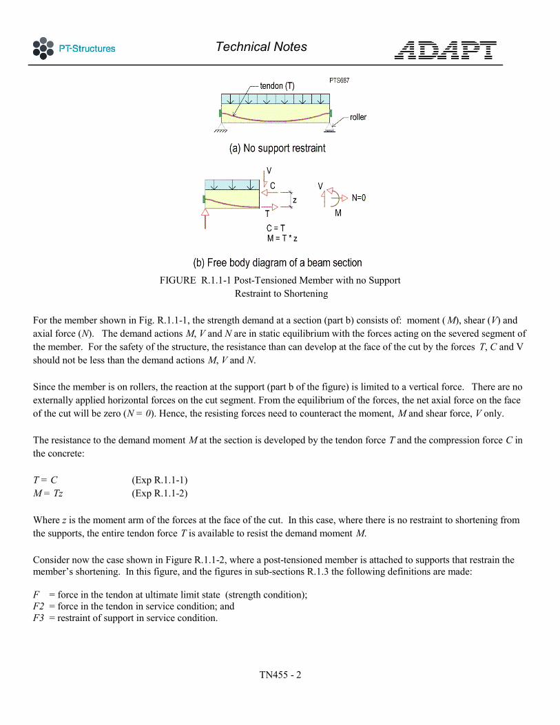
FIGURE R.1.1-1 Post-Tensioned Member with no Support
Restraint to Shortening
For the member shown in Fig. R.1.1-1, the strength demand at a section (part b) consists of: moment ( M), shear (V) and axial force (N). The demand actions M, V and N are in static equilibrium with the forces acting on the severed segment of the member. For the safety of the structure, the resistance than can develop at the face of the cut by the forces T, C and V should not be less than the demand actions M, V and N. Since the member is on rollers, the reaction at the support (part b of the figure) is limited to a vertical force. There are no externally applied horizontal forces on the cut segment. From the equilibrium of the forces, the net axial force on the face of the cut will be zero (N = 0). Hence, the resisting forces need to counteract the moment, M and shear force, V only. The resistance to the demand moment M at the section is developed by the tendon force T and the compression force C in the concrete: T = C (Exp R.1.1-1) M = Tz (Exp R.1.1-2) Where z is the moment arm of the forces at the face of the cut. In this case, where there is no restraint to shortening from the supports, the entire tendon force T is available to resist the demand moment M.
Consider now the case shown in Figure R.1.1-2, where a post-tensioned member is attached to supports that restrain the member’s shortening. In this figure, and the figures in sub-sections R.1.3 the following definitions are made: F = force in the tendon at ultimate limit state (strength condition); F2 = force in the tendon in service condition; and F3 = restraint of support in service condition.

Technical Notes
TN455 - 3
FIGURE R.1.1-2 Post-Tensioned Member with Support Restraint
At tendon stressing the supports shown absorb a part of the post-tensioning force, marked F3 in part (c) of the figure. The amount of the force F3 that is diverted to the supports depends on the stiffness of the supports; the remainder of the post-tensioning force results in precompression in the member. For ease of visualization, the member is modeled as shown in part (b). The springs attached at each end of the member represent the restraint of the supports to the shortening of the member.3 The discussion followed for the member in Fig. R.1.1-1 will be used here to determine the contribution of the tendon force to the safety of the member. Part (c) of Fig. R.1.1-2 is the free body diagram of the left segment of the member. The demand actions at the face of the cut are once more the moment M, shear V, and axial force N. In this case, however, from the equilibrium of the forces in the horizontal direction we have: N = F3 (Exp R.1.1-3)
Thus, in addition to the moment M and shear V, there is a net axial tension F3 that must be resisted by the actions developed at the face of the cut. From the equilibrium of the forces on the segment: C = F2 – F3 (Exp R.1.1-4)
Hence, the resisting moment at the face of the cut will be: M ~ F2z – F3e (Exp R.1.1-5) 3 There will also be a moment at the end of the member due to the shift of the restraining force ( F3) at the support from the support/member interface to the centroid of the member shown in part (b). This moment is not shown in the figure, since its presence does not impact the current discussion.

Technical Notes
TN455 - 4
Where e is the distance between the force F3 and the centroid of the compression force C. The approximation sign ( ~ ) is used, since the force F3 acts at the interface between the support and the member, but for the current discussion, it is shown at the centroid of the member, with the restraint modeled as a spring.
In summary, when a member is restrained at supports, the post-tensioning force available to resist the demand moment M is reduced. The amount of reduction, in this example F3, depends on the stiffness of the restraining supports. The preceding is a simplification of the mechanism for development of resistance in a post-tensioned member, intended to present the concept. With increase in applied load, there will be an increase in tendon strain, which in turn results in an increase in tendon force. At ultimate limit state, the force in the tendon ( F) is thus F2 + ∆F2, where ∆F2 is the increase in tendon force due to local strain. The amount of the increase depends on whether the tendon is bonded or unbonded. For bonded tendons, the increase is local and can bring the tendon’s stress to its ultimate strength ( fpu). For unbonded tendons the increase is typically considerably less.
To illustrate the concept, in the following the extreme condition of large support restraint is examined. In this condition, the entire post-tensioning is diverted to the supports, leading to cracks through the depth of a member. Non-prestressed reinforcement helps to control crack width and crack dispersion. To highlight the interaction of prestressing and the restraint of the supports, in the following the contribution of non-prestressed reinforcement is not accounted for. R.1.2 Unbonded Tendons; Safety and Restraint Cracks R.1.2-1 shows a member reinforced with unbonded tendons with a single crack that extends through the depth of the section (part a). The crack is from shrinkage of concrete and the full restraint of the supports A and B to free shortening of the member. Supports C and D are shown as roller supports. For simplicity, tendons are shown along a straight line; selfweight and external loads are not shown. Note that in part (a) of the figure, the tendon retains its force (F2) across the cracked section, but there is no compressive force on the face of the crack, since the member is assumed fully fixed against shortening at its end supports. The entire tendon force is diverted to the support A. An idealized free body diagram of the left segment of the member for the post-tensioning forces is shown in part (b). The restraint from the supports, F3 is equal to , the force in the tendon (F2 ) . With increase in the applied load, the member will develop hinge lines at the locations marked in Fig. R.1.2-2b. The downward displacement of the slab prior to collapse will elongate the tendons along their length, resulting in an increase (δF2) in the tendon force. The initial tendon force at location of through crack under service condition ( F2) will increase to its final value F as shown in part (c) of the figure. The impending failure mechanism re-establishes contact between the two sides of the crack, where a compressive force C will develop. For unbonded tendons, the increase in tendon force across the crack prior to failure will be partially transferred to the supports A and B4 because although the member itself is restrained against movement, the tendon can slide within its sheathing. At the ultimate state, the restraint from the supports increases to F4.
4 If the member length is longer than is common in building construction, the increase in tendon force can be absorbed by the increase in friction, but this seldom occurs in practical conditions.
Technical Notes
TN455 - 5
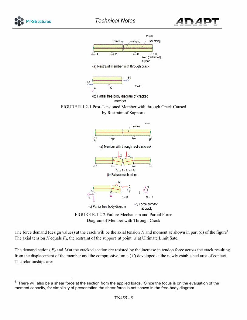
FIGURE R.1.2-1 Post-Tensioned Member with through Crack Caused
by Restraint of Supports
FIGURE R.1.2-2 Failure Mechanism and Partial Force
Diagram of Member with Through Crack
The force demand (design values) at the crack will be the axial tension N and moment M shown in part (d) of the figure5. The axial tension N equals F4, the restraint of the support at point A at Ultimate Limit Sate.
The demand actions F4 and M at the cracked section are resisted by the increase in tendon force across the crack resulting from the displacement of the member and the compressive force (C) developed at the newly established area of contact. The relationships are:
5 There will also be a shear force at the section from the applied loads. Since the focus is on the evaluation of the moment capacity, for simplicity of presentation the shear force is not shown in the free-body diagram.

Technical Notes
TN455 - 6
C = F – F4 (Exp R.1.1-6) M = C z, (Exp R.1.1-7) Where z is the lever arm between the centroids of the tension and compression forces, and F is the force in the tendon at the crack. The tensile force in the tendon that contributes to the resistance capacity of the cracked section is the difference between the force in the tendon at the crack (F) and the restraint of the support (F4). The partial free body diagram of the horizontal forces for the left segment of the member is shown in Fig. R.1.2-3. The figure shows the contribution of the friction forces (P) between a strand and its sheathing in developing the compression force (C). It is noted that the compressive force C that can be developed across the crack prior to the collapse of the member is limited to the friction force (P) that builds up between a strand and its sheathing (part b of the Figure). This is based on the initial premise that the support restraint at A is large enough to prevent the shortening of the member.
FIGURE R.1.2-3 Development of Friction Force P at Ultimate Strength
From part (b) of the figure: P = F - F4 (Exp R.1.1-8) From part (a) of the figure: C = F – F4 (Exp R.1.1-9) Where F4 is the restraint from the support at the ultimate limit state. Therefore, C = P (Exp R.1.1-10) To arrive at the upper bound for the moment that can possibly develop at the crack, the tendon is assumed to be stretched to its rupture force, recognizing that this is impractical for unbonded tendons, before a member can be considered “failed.” The force F in the tendon is calculated as:
Technical Notes
TN455 - 7
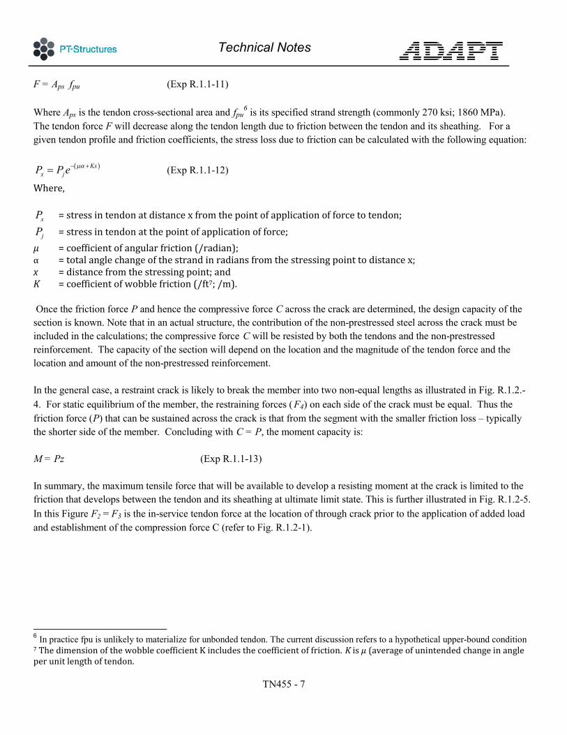
F = Aps fpu (Exp R.1.1-11) Where Aps is the tendon cross-sectional area and fpu
6 is its specified strand strength (commonly 270 ksi; 1860 MPa). The tendon force F will decrease along the tendon length due to friction between the tendon and its sheathing. For a given tendon profile and friction coefficients, the stress loss due to friction can be calculated with the following equation:
( )Kxx jP P e µα− += (Exp R.1.1-12)
Where,
xP = stress in tendon at distance x from the point of application of force to tendon; jP = stress in tendon at the point of application of force;
µ = coefficient of angular friction (/radian); α = total angle change of the strand in radians from the stressing point to distance x; x = distance from the stressing point; and K = coefficient of wobble friction (/ft7; /m). Once the friction force P and hence the compressive force C across the crack are determined, the design capacity of the section is known. Note that in an actual structure, the contribution of the non-prestressed steel across the crack must be included in the calculations; the compressive force C will be resisted by both the tendons and the non-prestressed reinforcement. The capacity of the section will depend on the location and the magnitude of the tendon force and the location and amount of the non-prestressed reinforcement. In the general case, a restraint crack is likely to break the member into two non-equal lengths as illustrated in Fig. R.1.2.-4. For static equilibrium of the member, the restraining forces ( F4) on each side of the crack must be equal. Thus the friction force (P) that can be sustained across the crack is that from the segment with the smaller friction loss – typically the shorter side of the member. Concluding with C = P, the moment capacity is: M = Pz (Exp R.1.1-13) In summary, the maximum tensile force that will be available to develop a resisting moment at the crack is limited to the friction that develops between the tendon and its sheathing at ultimate limit state. This is further illustrated in Fig. R.1.2-5. In this Figure F2 = F3 is the in-service tendon force at the location of through crack prior to the application of added load and establishment of the compression force C (refer to Fig. R.1.2-1).
6 In practice fpu is unlikely to materialize for unbonded tendon. The current discussion refers to a hypothetical upper-bound condition 7 The dimension of the wobble coefficient K includes the coefficient of friction. K is µ (average of unintended change in angle per unit length of tendon.

Technical Notes
TN455 - 8
FIGURE R.1.2-4 Partial Free Body Diagram of a
Non-Symmetrical Member Cracking
FIGURE R.1.2-5 Member with Unbonded Tendon; Tendon
Force Diagram at Service and Ultimate Limit State In the preceding diagram, the force (F – F4) is the force that will be available to resist applied moments – the moment capacity of the section. The force (F – F4) is the friction force between the strand and its sheathing. From the preceding diagram, it is concluded that when members reinforced with unbonded tendons experience excessive support restraints, the friction between a tendon and its sheathing plays a role in the strength available from the tendon at the member’s ultimate strength capacity. The larger the friction force between a tendon and its sheathing, the greater will be the available tendon strength to resist applied loads. R.1.3 Bonded Tendons; Safety and Restraint Cracks Members reinforced with bonded tendons develop a larger moment capacity at locations of restraint cracks compared to members that are reinforced with the same amount of unbonded post-tensioning. There are three reasons. First, bonded tendons can typically develop their specified strength ( fpu) prior to failure, whereas members reinforced with unbonded tendons tend to undergo large deflections, and reach failure due to crushing of concrete or excessive deflection,

Technical Notes
TN455 - 9
before tendons reach their specified strength (fpu). Consequently, ACI 3188 [ACI 318, 2011] and EC2 [EC2, 2004] specify a significantly lower permissible stress (fps) for unbonded than bonded tendons for flexural capacity design of concrete members. Depending on the span dimensions for unbonded tendons, ACI 318 limits the increase in tendon stress at ultimate strength to between 30 to 60 ksi (206 to 413 MPa), whereas in EC2 the increase is limited to merely 100 MPa 9 (15 ksi). This is about 7 to 9 % gain in strength over service condition, leaving about 30% of a tendon’s strength untapped at member failure. Second, for members reinforced with bonded tendons, the increase in demand moment at a point results in an increase in the tendon force at the same location. This local increase in tendon force is not compromised by the restraint of the supports. On the other hand, for unbonded tendons – as outlined in the previous sub-section – support restraints can diminish the effectiveness of local increase in tendon force in resisting an applied moment. This is explained in greater detail in what follows. Third, compared to unbonded tendons, for bonded tendons the higher friction of between the strands and the sheathing at stressing works advantageously at the strength limit state of a cracked section. Consider the member with a bonded tendon shown in Fig. R.1.3-1. Let the restraint from the supports be large enough to cause cracking as shown in part (a). The force in the tendon at the time of grouting follows essentially the friction diagram shown in part (b). Let the force in tendon at location of crack in service condition be F2. For the static equilibrium of the arrangement shown, F2 is equal to the restraint of the support (F3) while the gap at the crack is open. An increase in the applied moment at the crack location will tend to elongate the tendon locally leading to an increase in the tendon force to δ F2 (part c of the Figure). The demand actions at the location of crack (part d of the Figure) are M and N, where from equilibrium of the forces N is equal to F3, the force due to restraint of the support10. The tensile force available to resist the demand actions at the crack location is: T = F2 + δ F2 – F3 (Exp R.1.1-14) Since at location of crack F2 = F3, the available force (T) to resist the induced moment will be equal to δ F2 . Likewise from equilibrium of forces the compression force C is C = (F2 + δ F2) – F3 = δ F2 (Exp R.1.1-15) The moment that can be developed at the crack M is equal to: M = Cz = δ F2 z (Exp R.1.1-16)
8 ACI 318-11 Section 18.7 9 EC2 Section 5.10.8(2) 10 Obviously, there will be a shear at the cut and the tendon will not be normal at the section, leading to both horizontal and vertical force components. These will change the numerical values, but they do not affect the concept being discussed. Hence, they are not included in order to keep the focus on the critical aspects of the concept.
Technical Notes
TN455 - 10
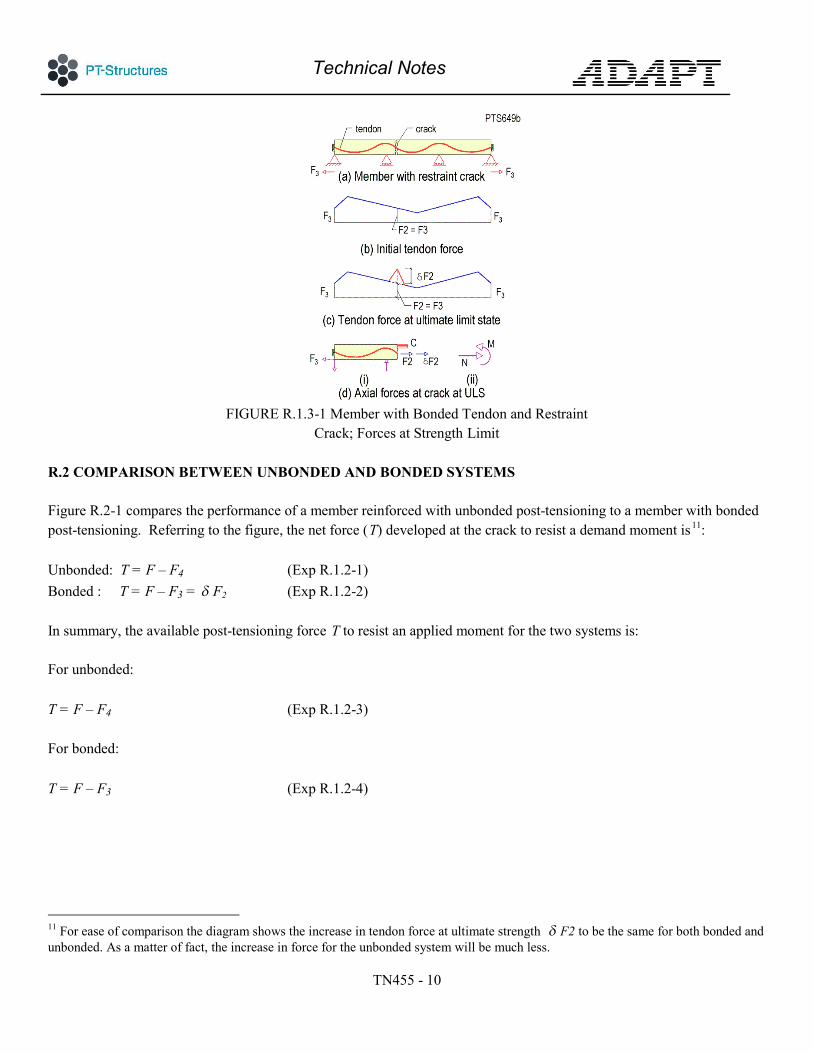
FIGURE R.1.3-1 Member with Bonded Tendon and Restraint
Crack; Forces at Strength Limit R.2 COMPARISON BETWEEN UNBONDED AND BONDED SYSTEMS Figure R.2-1 compares the performance of a member reinforced with unbonded post-tensioning to a member with bonded post-tensioning. Referring to the figure, the net force (T) developed at the crack to resist a demand moment is11: Unbonded: T = F – F4 (Exp R.1.2-1) Bonded : T = F – F3 = δ F2 (Exp R.1.2-2) In summary, the available post-tensioning force T to resist an applied moment for the two systems is: For unbonded: T = F – F4 (Exp R.1.2-3) For bonded: T = F – F3 (Exp R.1.2-4)
11 For ease of comparison the diagram shows the increase in tendon force at ultimate strength δ F2 to be the same for both bonded and unbonded. As a matter of fact, the increase in force for the unbonded system will be much less.

Technical Notes
TN455 - 11
FIGURE R.2-1 Comparative Distribution of Force in Tendon at Ultimate Limit State
for the bonded and unbonded post-tensioning systems
R.3 REFERENCES ACI 318-11, (2011), “Building Code Requirements for Structural Concrete (ACI 318-11) and Commentary,” American Concrete Institute, Farmington Hill, MI 48331, www.concrete.org, 503 pp. EC2 – 1992-1-1:2004, (2004) “Eurocode 2: Design of Concrete Structures, Part 1-1: General rules and rules for buildings,” European Committee for Standardization, CEN, Brussels. ADAPT TN454, Aalami, B. (2015), “Crack Mitigation in Post-Tensioned Members, “ ADAPT Corp. www.adpatsoft.com; www.PT-Structures, pp. 40, 2015 ADAPT TN458, (2015), “ Shortening Estimate of Post-Tensioned Members,” ADAPT Corp. www.adpatsoft.com; www.PT-Structures, pp. 16, 2015 R.4 NOTATIONS C = compression developed in section at ultimate limit state; F = Total force in tendon at ultimate limit state; F2 = prestressing force; F3 = Force at support restraint; also force in tendon at location of through cracks under service condition; F4 = Force in tendon at support restraint under ultimate limit condition; M = demand moment at location of through crack;
Technical Notes
TN455 - 12
N = demand axial force at location of through crack; T = amount of tendon force available to resist the demand moment; δ F2 = local increase in tendon force at ultimate limit state; www.ADAPTsoft.com www.PT-Structures.com
This publication is intended for the use of professionals competent to evaluate the significance and limitations of its contents and who will accept responsibility for the application of the materials it contains. The author and the affiliated organizations report the foregoing material as a matter of information and therefore disclaim any and all responsibility for application of the stated principles and procedures or for the accuracy of the sources. The author and the affiliated organizations in publishing these Technical Notes make no warranty regarding the recommendations contained herein, including warranties of quality, workmanship or safety, express or implied, further not limited to, implied warranties or merchantability and fitness for a particular purpose.