tms 5.1 tutorial - two rivers technologies · the equipment types in tms are divided between fixed...
TRANSCRIPT

TMS 5.1 Tutorial
Mechanical Integrity Data Management and Reporting System

2

3
TABLE OF CONTENTS
SECTION Page
Initial Startup 4
1 Fundamental Features 5
2 Equipment Data Forms 6
Fixed Equipment 6
Non-fixed Equipment 17
Grids 19
3 Inspection Data Forms 21
4 Reports 31
5 Setting Up New Fixed Equipment 40
Appendix 53
Standards and conventions 54
Thickness Evaluation Chart 58
Administrative Options 60
Short cuts 62
4
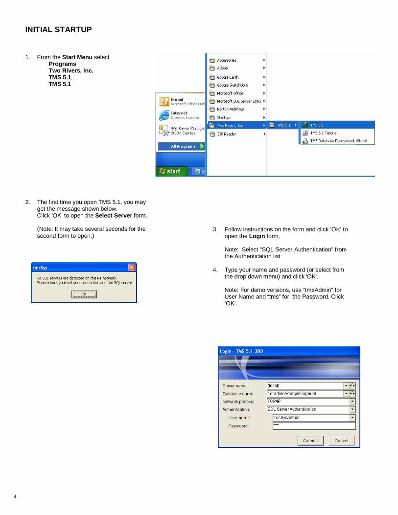
1. From the Start Menu select Programs Two Rivers, Inc. TMS 5.1, TMS 5.1
INITIAL STARTUP
2. The first time you open TMS 5.1, you may get the message shown below. Click ’OK’ to open the Select Server form. (Note: It may take several seconds for the second form to open.)
3. Follow instructions on the form and click ‘OK‘ to open the Login form. Note: Select "SQL Server Authentication" from the Authentication list
4. Type your name and password (or select from the drop down menu) and click 'OK'. Note: For demo versions, use “tmsAdmin” for User Name and “tms” for the Password. Click ‘OK‘.

5
Double Click on List Form In most cases, double-clicking (two left mouse button clicks in rapid succession) on an entry on a list form will open a detailed information form pertaining to the selected entry. For example, double-clicking on a piece of equipment on one of the Equipment List forms opens the General Information form for that piece of equipment.
1 FUNDAMENTAL FEATURES This section will give you an overview of navigation through TMS and discuss some of the fundamental functional features.
Caption and Menu Bar The TMS screen Caption shows the SQL Server database server, the TMS database name and the facility currently active . The Menu Bar is the main navigation tool in TMS . It is always active and shown at the top of the screen. The menu headings (Equipment, Lists , …) do not change. Navigating through TMS is straightforward. Simply select one of the major headings, then click on a menu item to open a related form. If you change from one major heading to another while forms or reports are open, those objects are closed automatically before the new list is opened.
Caption
Menu Bar
Right Click Menus (RCM) are available on most list forms as well as on many individual fields to allow the user a convenient way to choose a task or open an object. The RCM is opened by placing the cursor on the line or field of interest and then pressing the right button on the mouse.
Right Click Menus
Drop Down Lists Drop down lists are found on many fields to make data entry easier and more consistent. The drop down list is usually identified by the "down arrow point" on the right side of the field. In some cases, the arrow point is not visible until the user clicks on the field.

6
General Information Form You now can open the General Information form for the selected piece of equipment by either of the following actions
• Right click on the selected line and choose "General Information" from the menu, as shown above, or • Double click on the selected line.
Note: The General Information form may take several seconds to load, depending on the speed of your computer.
2 EQUIPMENT DATA FORMS This section is for use with the Sample Plant, TRT data for a quick tour of the equipment data forms. Fixed Equipment The equipment types in TMS are divided between fixed equipment (pressure vessels / heat exchangers, tanks and piping) and non-fixed equipment (everything else except pressure relief devices—PRDs.) Most TMS users usually will be using the fixed equipment General Information and Inspection Summary forms and reports for data entry, evaluation and reporting. Many of the exercises in this tutorial will be for pressure vessels; however, the main (upper) part of the General Information form for piping and tanks is similar to the pressure vessel form, but specific to the type of equipment. Structure & Use , Components and Component Details forms also vary for each type fixed equipment. Examples of the tank and piping General Information forms are shown on pages 13 and 14, respectively.
Equipment List 1. On the Menu Bar, click on 'Equipment', then 'Pressure Vessels’ to open the Pressure Vessel Equipment List .
2. Select "300 #3 Deaerator" on the Pressure Vessel Equipment List .
Note: This pressure vessel will be used as the example for many of the exercises in this section. If you wish, you may minimize the Pressure Vessel Equipment List form by clicking on the 'Minimize' button in the upper right corner of the form. (Don't close the form; it must be open while you are working with any pressure vessel form.)

7
The Structure & Use sub-form is visible when the General Information form opens. All the values you see may be edited by the user; however, we recommend you don't change them right now.
1. Click the 'Heat Exchanger' check box to activate the 'TEMA Designation' field and the fields on the 'Tube Bundle' sub-form.
2. Click on the 'Tube Bundle' tab to look at the available fields. Add information if you wish.
3. Move back to the Structure & Use sub-form, and uncheck the 'Heat Exchanger' box. Choose "Yes" on both messages.
Structure & Use
Heat Exchanger Tube Bundle

8
Important Note: TMS calculates the required minimum thickness (Tmin) based on hoop stresses due to internal pressure in accordance with recognized formulae and information entered by the user. These values are calculated only for convenience to get an initial estimate of a reasonable value for 'Tmin Governing'. 'Tmin Governing' is used by TMS in setting up graphs, calculating 'Years to Tmin", etc. The user of the program should always check the value of 'Tmin Governing' to verify that it is appropriate for the intended use. Many factors affect the determination of the required minimum thickness for any piece of equipment. Due to the significant structural and safety issues involved, such determination should be made only by an experienced qualified engineer.
3. Move the cursor to the 'Tmin Calculated' field and right click to open the menu.
4. Select "Tmin Report " to look at the calculation of the Tmin value. (Shown on facing page.)
5. Close the Tmin Calculation Details Report form by using the 'Close' button (X) on the form or the 'Close' button on the tool bar.
6. Close the Component Details form.
1. When you finish looking at the information in the Structure & Use sub-form, click on the ‘Components’ tab.
2. Double click on “E. Head” to open the Component Details form.
Components
Component Details

9

10
Inspection Schedule 1. Click on the 'Inspection Schedule' tab to view the 'Last Inspection Date', 'Inspection Interval' and 'Next Inspection Date' fields for
the different inspection types. The 'Last Inspection Date' for each type inspection is automatically displayed based on the information contained in the Inspection List form shown on the top of the facing page. In the example, the latest inspection date of "04/19/2008" includes ’Thickness’, ‘External' and 'Internal' inspection types, and all are shown on the 'Inspection Schedule' form.
The user can set the Inspection Interval directly or choose to have TMS calculate the inspection interval based on the appropriate API standard. For pressure vessels, as shown, the next inspection interval for ‘Internal’ and ’Thickness’ inspection is calculated by comparing one-half the remaining life based on thickness measurements and Tmin, and the maximum recommended interval of 10 years. The "calculated" inspection interval for External is set to the maximum recommended interval of 5 years.
2. To have TMS calculate the inspection interval for the next thickness inspection, place the cursor on the ‘Thickness' 'Inspection Interval' field and right click to open the menu.
3. Click "Calculate Inspection Interval" and answer "Yes" to the message boxes (shown on the facing page).
The 'Next Inspection Date' value defaults to the 'Last Inspection Date' value plus the 'Inspection Interval' when one of those two fields is changed. The user can also change the 'Next Inspection Date' manually.

11
4. Note that both the 'Retirement Date' and the 'Inspection Interval' values have changed.

12
Attributes 1. Click on the ‘Attributes’ tab.
Attributes are custom fields which may be defined by a Manager or higher level using Options / Administrative Options / Equipment Attributes .
2. Once an attribute has been defined, any user except Report User level may add an attribute value. To try this feature, select "Area Supervisor:" from the drop down list and add your name in the 'Attribute' field just to the right of the colon.
3. Use the drop down list to look at other currently defined attributes.
Related Equipment 1. Click on the 'Related Equipment' tab.
By using the drop down list, the user may select any number of pieces of equipment to be shown as related to the #3 Deaerator. The drop down list shows the type, Equipment ID and Name for every piece of equipment that has been entered into the TMS data files.
2. Add additional related equipment if you wish and put any comments in the 'Relationship Description' field.
NOTE: From the Main Menu , you can click on 'Options / System Options' to automatically update the corresponding related equipment.

13
To add a new link, select the blank top line then click on the Browse icon to search for the desired file. Once the file path is selected, press ‘Enter’ to save the path.
File Links 'File Links' are used to link to documents that are stored in other applications. Linked documents may be text, spreadsheets, drawings, photographs, etc. The only 'File Links' information stored in the TMS database is the file path and a description, as shown below. Because the linked documents are stored outside the TMS database, there is no limit on the size or number of linked files (other than the capacity of the storage device housing the files.) Equipment Inspection forms also have a file link feature on the 'Documents' tab so that documents that relate to a specific inspection date can be linked. NOTE: For network applications, it is important to store the linked files on a central server with a common drive name used by all TMS client computers.
To open an existing file, select the desired file path and click on the Open Folder icon.

14
Images The 'Images' feature is used to store some common graphic files (.jpg, jpeg, .gif and .bmp) directly in the database. The two major advantages of using 'Images' rather than 'File Links' to store graphic files are: (1) Unlike file links, the images are stored directly in the TMS database, so they can be accessed by any TMS client
computer with the appropriate user level, and
(2) 'Images' graphics can be incorporated into equipment "Complete Details" reports and 'Inspection Details' reports.
We recommend using efficient graphic files such as .gif and .jpg files. It is recommended that .bmp files not be used as they tend to be relatively large. Also, you may want to limit the number of graphic files stored in 'Images' to the most important ones.
To add a new graphic file, first click on the 'New Image' button.
Then click on the 'Load Image' button and browse to select the desired file.
NOTE: The image preview shown in the viewer may be skewed depending on its original proportions. Double click on the preview to open a window to see the image in correct proportion.
15
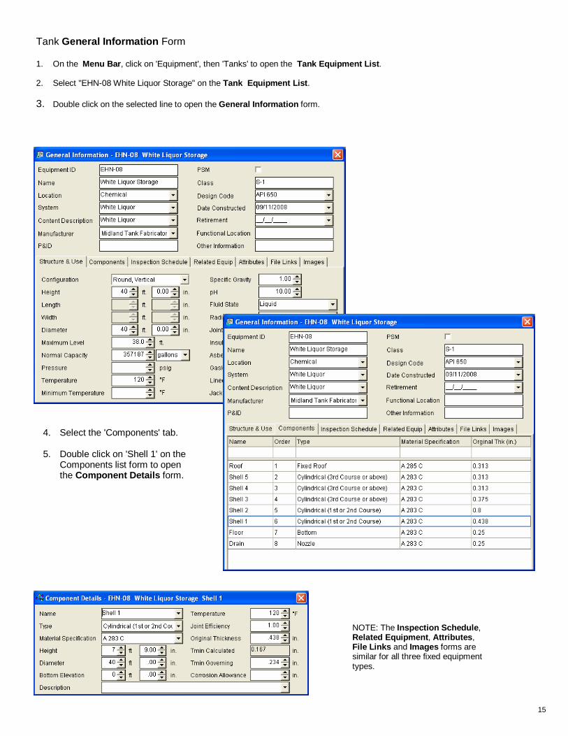
Tank General Information Form 1. On the Menu Bar , click on 'Equipment', then 'Tanks' to open the Tank Equipment List .
2. Select "EHN-08 White Liquor Storage" on the Tank Equipment List . 3. Double click on the selected line to open the General Information form.
4. Select the 'Components' tab.
5. Double click on 'Shell 1' on the Components list form to open the Component Details form.
NOTE: The Inspection Schedule , Related Equipment , Attributes , File Links and Images forms are similar for all three fixed equipment types.

16
Piping General Information Form 1. On the Menu Bar, click on 'Equipment', then 'Piping' to open the Piping Equipment List .
2. Select "01-2899 Ethylene Glycol Transfer Line". 3. Double click on the selected line to open the General Information form.
4. Select the Segments tab.
5. Double click on 'Seg 3' on the Segments list form to open the Segment Details form.
NOTE: 'Tmin Pressure' is calculated using internal pressure and hoop stress and 'Tmin Structural' is calculated as a percentage of the standard wall thickness or as a specific thickness set by the user. Tmin Governing defaults to the higher of the two values.

17
…. but the Structure & Use form is specific to each type of equipment. NOTE: The Related Equipment , Attributes , File Links and Images forms are the same for all equipment types.
Non-fixed Equipment The main part of the General Information form is very similar among the other types of equipment …..
Non– Fixed Equipment Now that you've gone through the General Information forms for fixed equipment, look at some non-fixed equipment by making other selections from the 'Equipment' heading on the menu bar. In addition to fixed equipment, TMS has 7 categories of non-fixed equipment. Examples of the General Information forms for Pumps and Electric Motors are shown below.
18
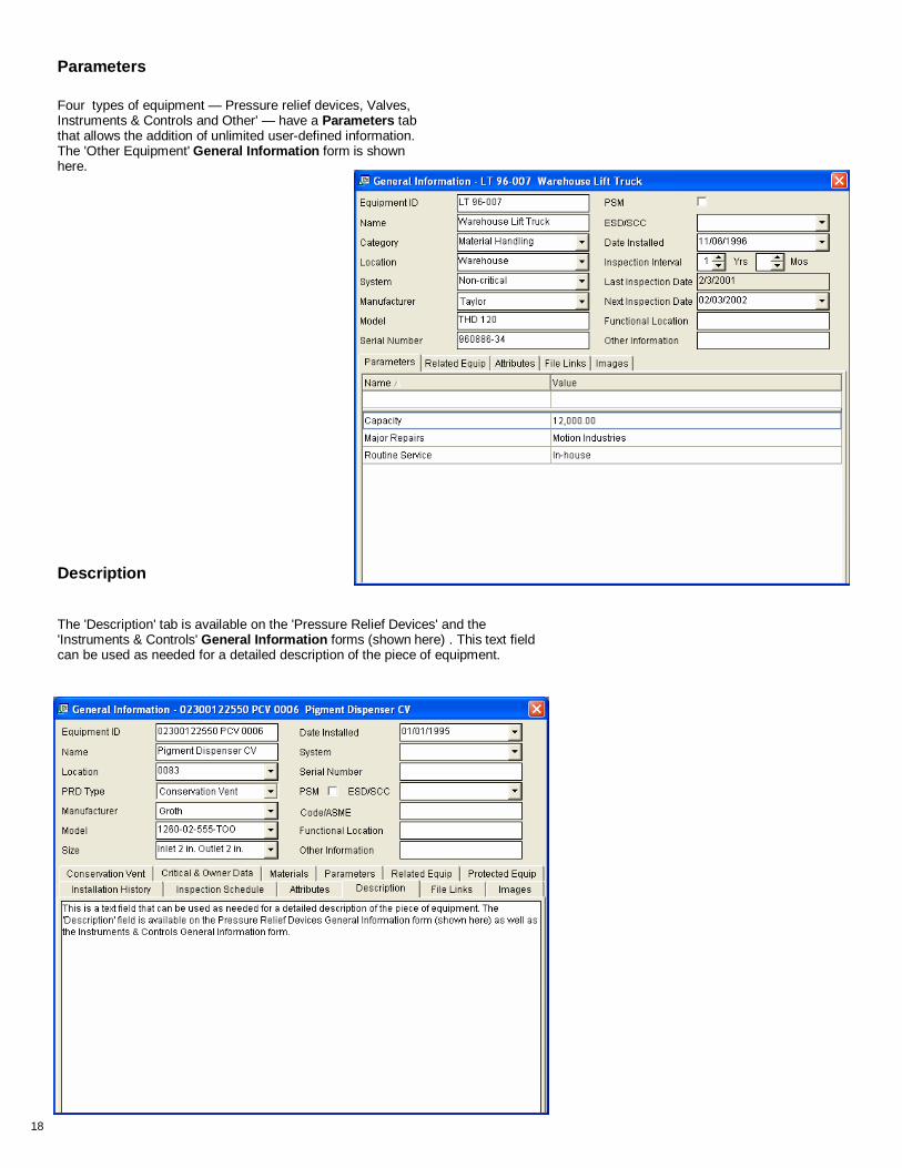
Four types of equipment — Pressure relief devices, Valves, Instruments & Controls and Other' — have a Parameters tab that allows the addition of unlimited user-defined information. The 'Other Equipment' General Information form is shown here.
Parameters
Description
The 'Description' tab is available on the 'Pressure Relief Devices' and the 'Instruments & Controls' General Information forms (shown here) . This text field can be used as needed for a detailed description of the piece of equipment.

19
Grids Grids are two dimensional arrays of thickness measurement locations and are a major feature of TMS. Thickness data entry, editing, evaluation and reporting are related back to the grid or grids for a specific piece of fixed equipment. A grid gives a practical and useful view of the thickness data for one or more components of a piece of equipment. To view grids: 1. On the Pressure Vessel Equipment List form,
select "300 #3 Deaerator".
2. Right click to show the drop down list and select ‘Grids'.
Note: Although the form you are viewing is already populated with thickness measurement data, new data can be entered in a grid from the keyboard, imported from an existing file or downloaded directly from a data logger. Also, the existing data can be edited or overwritten. (Don't change it now, however.) In most cases, you will be entering new thickness data into the grid using the Inspection Summary form shown on page 21. The 'Setting up new equipment' exercise beginning on page 40 will lead you through setting up a new thickness grid and entering data from the Inspection Summary form.
3. On the Grid List , select "Shell" .
4. Right click to show the drop down list and select 'View Grid', then ‘Thickness Readings‘ to view the Thickness Measurements grid form shown below.
6. Click on the 'Inspection Date' drop down menu to view thickness measurement data from previous inspections.

20
This page intentionally left blank.

21
3 INSPECTIONS Inspection forms are the heart of the TMS 5.1 inspection data entry process. Using these forms, the user is able to enter text data, thickness measurements, checklists, attached documents and cost data, all in one place. 1. Right click on "300 #3 Deaerator" and select
'Inspections' to open the Inspection List form.
2. Right click on 04/19/2008, Shelby County Industrial Services and select Inspection Summary .
3. Double click on the 'Description' field for the "NDE" label to open the Standard Inspection Summary Description form shown to the right. This form allows the user to store and apply standard descriptive phrases or paragraphs for frequently used descriptions.
The Inspection Summary form is used to capture all the information for a single inspection. Click on each tab to see the corresponding information.
Summary 1. The 'Summary' form is used to enter headings
('Label Name') and written descriptions of inspection, testing and evaluation.
2. Right click on the 'Description' field and select 'Zoom Field' to view the entire description shown below.

22
2. Use the right-click menu to view the options for importing, exporting and viewing the thickness data.
3. Select 'Column History Graph' to open the graph shown below.
Grids The 'Grids' form is used to select grids used for entering or viewing thickness measurement data. 1. Use the right-click menu or double click to
open the "All-Single Column" grid.

23
Thickness Testing Equipment The 'Equipment' form is used to select UT Thickness measurement equipment from pre-defined lists. Note: To add equipment to the list, select 'Lists \ Inspection Equipment' from the main menu, as shown below.
Personnel The 'Personnel' form is used to select inspection personnel from pre-defined lists. Note: To add personnel to the list, select 'Lists \ Inspection Personnel' from the main menu.

24
Documents The 'Documents' form is the same as 'File Links' on the General Information form, except that it links documents specifically related to the selected inspection date, such as photographs, digitized radiographs, additional reports, etc.
Time & Cost Time & Cost' allows the user to enter summary time and cost data for the inspection. This information can be reported in detail or summary form.
Images The 'Images' form is the same as 'Images' on the General Information form, except that it contains graphic files specifically related to the selected inspection date, such as photographs and digitized radiographs.

25
This page intentionally left blank

26
SmartChecklists One of the most widely used means of data collection is the checklist. The checklist format is effective because it combines a consistent outline of the information to be gathered along with a concise presentation of the results. However, because checklists are typically paper-based documents, the data obtained is not always easy to evaluate and may not even be readily available. The SmartChecklists feature is used to efficiently obtain and store data from surveys, periodic inspections and other applications where a checklist format is most appropriate. The checklist data is evaluated and reported in a manner that facilitates identifying problems, tracking trends and meeting industry and regulatory reporting requirements. SmartChecklists are set up in a consistent format, designed for ease of use and functionality. The checklist itself consists of a number of inspection items along with more detailed descriptions or explanations for each item. A checklist is designed with two or more standard response descriptions along with a corresponding integer value for each response description.
Data Collection SmartChecklists are designed to make collection simple and easy. Using drop-down menus, each checklist item is assigned a numeric value and a corresponding description. The data can be entered in two ways: Paper forms —facing page This is the time-honored method of collecting checklist data and in many cases is still the most effective. The SmartChecklists program allows the user to print out professional looking paper forms for field data collection. The results are then keyed into the SmartChecklist data forms.
Pocket PC. SmartChecklists can be uploaded to a PDA for use by interviewers or inspectors. After the checklists are completed, the results can be download directly to the PC

27

28
Notes The Notes form is a simple to use and powerful information storage and retrieval tool. Text information may stored either by direct entry from the keyboard or by "cutting and pasting" from another text document. Use the 'Subject' and 'Subheading' fields to develop your own filing system for notes.
1. On the Vessel Equipment List form, right click on "300 Deaerator".
2. On the menu, select 'Notes' to open the Notes list form.
3. Right click and choose View/Edit Note (or just double click on the line) to enter or edit data.

29
Tasks The Tasks form is a versatile tool that allows the user to schedule any sort of task at a future date. The task may be a special inspection, such as the eddy current test shown in the example, or maintenance, adjustment, repair, etc.
1. To create a new task, right click on the piece of equipment and select 'Tasks' to open the Tasks form.
2. Next, enter the desired data for 'Date Due', 'Type' and 'Contractor' in the 'New Record line, then press 'Enter'.
3. Right click or double click on the line you just entered to open the Task Details form.
4. Enter as much detail as is needed in the 'Description' window. Once a task is complete, fill in the 'Date Completed' field in the top part of the form, along with any additional comments or descriptions of the work. The record is then part of the task history for the piece of equipment.
There is also a Time & Cost form similar to the one previously discussed for inspections.

30
This page intentionally left blank

31
4 REPORTS There are well over 200 standard reports in TMS 5.1. Most of these reports have associated filter forms that allow the user to focus on specific information. This section will review a few of the most widely used reports and filters.
Note that the unfiltered report requires 51 pages.
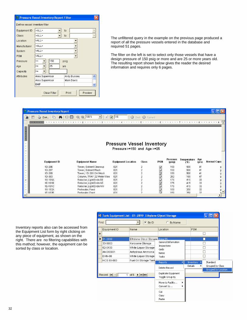
Inventory Inventory reports are lists of the same type equipment that can be sorted, filtered and/or grouped by selecting various fields and/or attributes from the appropriate Filter form as shown below.
32
The unfiltered query in the example on the previous page produced a report of all the pressure vessels entered in the database and required 51 pages. The filter on the left is set to select only those vessels that have a design pressure of 150 psig or more and are 25 or more years old. The resulting report shown below gives the reader the desired information and requires only 6 pages.
Inventory reports also can be accessed from the Equipment List form by right clicking on any piece of equipment, as shown on the right. There are no filtering capabilities with this method; however, the equipment can be sorted by class or location.
33
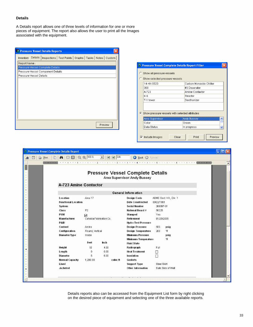
Details A Details report allows one of three levels of information for one or more pieces of equipment. The report also allows the user to print all the Images associated with the equipment.
Details reports also can be accessed from the Equipment List form by right clicking on the desired piece of equipment and selecting one of the three available reports.

34
Inspections There are more Inspections reports than any other type. On this page and the next are a couple of the most commonly used, but all are useful. (Take a look at the Inspection Checklist and Inspection History reports as well.)
The Inspection Details with Critical TMLs is available for tanks and piping as well as pressure vessels. It gives the reader a comprehensive look at the inspection summary and the most critical TMLs (those with the shortest time to TMin.) Images can be printed with the report as well.

35
The Inspection Dates report is available for all types of equipment. In this example, the report shows internal inspection dates due within a specified time period.
Note: A report for all upcoming inspection dates for all types equipment can be set up by selecting Options / System Options from the main menu, then clicking on the 'Inspection' tab. The report may be set to automatically open on startup of TMS. It also can be viewed by clicking on Reports from the main menu and selecting 'Scheduled Equipment Inspection' from the list.

36
Test Points The Test Points tab allows the user to choose either 'Test Points' or 'Test Points Details' reports. Each type can be extremely helpful (and save lots of time, especially if you have a large number of TMLs to analyze.)
You can view TML thickness or any of the other options shown in the Grid Type drop down list shown in the filter form to the right. Values above or below a specified value can be printed in a different color or highlighted (as shown in the example below.)

37
Graphs The Graphs tab allows the user to choose any of four thickness graphs. Note: The Settlement Graph is available only for tanks.
38
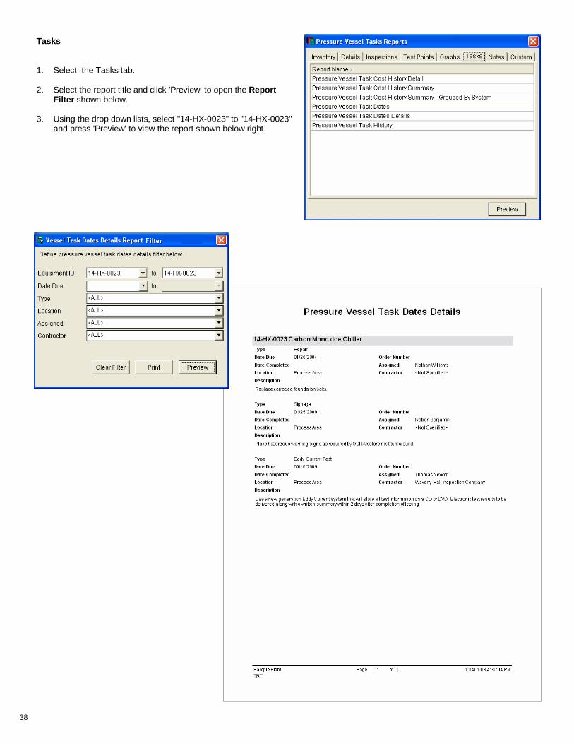
Tasks 1. Select the Tasks tab.
2. Select the report title and click 'Preview' to open the Report
Filter shown below.
3. Using the drop down lists, select "14-HX-0023" to "14-HX-0023" and press 'Preview' to view the report shown below right.

39
Notes History Note that this report can be searched by key word

40
8. From the main menu, click on 'Reports' then select 'Pressure Vessels'.
9. On the Pressure Vessel Reports form, select the 'Details' tab, then click on "Pressure Vessel Complete Details".
10. Press the 'Preview' button to open the Pressure Vessel Complete Details Report Filter form. Click on the 'Show selected pressure vessels' radio button, select "091771-ANB" and press 'Preview' to check your work. The report should look just like the one on the facing page. NOTE: You can also view the report by right clicking on '091771-ANB' on the Pressure Vessel Equipment List , then selecting 'Reports' / 'Details' /'Complete'.
5 SETTING UP NEW FIXED EQUIPMENT 1. Click on the Equipment menu.
2. Select 'Pressure Vessels' to open the Pressure
Vessel Equipment List .
3. Click on the ‘New Record Line’ and enter the following values: Equipment ID “091771-ANB” Name “Deaerator” Location “Power House” (Use the drop down list or just start typing.)
4. Press 'Enter'
5. Right click on the new record and select 'General Information.'
6. Fill in the information from the "Pressure Vessel Complete Details" report shown on the facing page. Note: Once you have entered information on the top part of the General Information form and the Structure & Use subform , click on the Components tab.
7. Enter the information for each component in the order shown on the report. (Note that for each new line, the Type, Materials Specifications and Original Thk will autofill with information from the last line entered.)
8. Open the Components Details form for each of the components by right - clicking or double clicking on the line. Enter a joint efficiency of 1.0 for each head component and 0.85 for each shell component.

41

42
1. Select 'Pressure Vessels' from the Equipment menu to open the Pressure Vessel Equipment List .
2. Click on "091771-ANB" and right click to open the RCM.
3. Click on 'Grids' to the Grid List form.
4. Right click on the Grid List form and select 'Create Grid'.
Setting up Test Point Grids
4. On the Test Point Setup Wizard , select the first option button 'Create Test Point Labels Manually'
5. In the Grid Name field, enter “Heads & Shell” and click 'Next' Note: Try to keep grid names short, about 12 characters max.
6. Select the first option button 'Enter number of columns'
7. Enter “4” and click 'Next'
8. Select the first option button 'Enter number of rows'
9. Enter “21” and click 'Next'
10. Select the first option button
11. Enter “0” and “90” and click 'Next'
12. Select the first option button
13. Enter “1” and “1”.
14. Check the 'Include Prefix' check box and enter "TML-".
15. Press 'Tab' to look at the sample row labels on the form.
16. Click 'Finish'
17. Click 'OK'

43
Assign Components to Grids 1. Right click (or double click) on "Heads & Shell"
on the Grid List form to open the Test Point Grid Details form.
2. In the 'Component' field for TML-1, type or choose “E. Head” from the drop down list. Repeat for TML-2 and TML-3.
3. For TML-4 through TML-8, choose "Shell 1".
4. For TML-9 through TML-13, choose "Shell 2".
5. For TML-14 through TML-18, choose "Shell 3".
6. For TML-19 through TML-21, choose "W. Head".
7. Check the box 'Use component original thickness and Tmin for grid scale'
8. Click ‘Lock‘.
Comments on setting up Grids General layout Always keep in mind that for circular pieces of equipment (almost everything), a grid "column" may be thought of as a line perpendicular to the circumference of the equipment (or of a component) and a "row" as a line parallel to the circumference. It does not matter if the piece of equipment has a horizontal or a vertical orientation. Be consistent in setting up grids. Think about how your thickness measurement locations will be laid out and design grids accordingly. It is best to have some written guidelines for grid configuration and naming conventions. Here are some suggestions: • Typical grid layouts – Single column or 2 dimensional grid. • Column names – Examples are degrees, compass headings, Top, Btm, clock position, etc. • Row names – Sequential numbers (with or without prefix and/or suffix) or distances.
How many grids per piece of equipment or piping? Although TMS 5.1 allows the user to set up any number of grids per piece of equipment, in general, the fewer the better. For example, In the example just completed, the grid "Heads & Shell" covers the main structure of the vessel, rather than creating 5 separate grids for "E. Head", "Shell 1", etc. For additional components, such as nozzles, another grid could be created. Why assign components to the grids? Assigning components to the grid tells the program what values to use for each row. For example, when TMS is calculating Retirement date for a piece of equipment, it uses the Tmin governing value for each component. In addition, assigning components makes it easy to find the test point locations on the various thickness reports and graphs. Make grid, component, row and column names as short as possible. The grid reports in TMS 5.1 are designed to get as much useful data on a page as possible while still being easy to read. As a result , the combined row names and assigned component names are limited to a total of about 14 characters.
NOTE: For an alternative and sometimes quicker way to assign components, see the Short Cuts section of this Tutorial.

44
Inspection Summaries - Fixed equipment 1. Close all forms except the Pressure Vessel
Equipment List .
2. Right click on "091771-ANB" and select 'Inspections'.
3. On the Inspection List form New Record, click on the down arrow in the 'Inspection Date' field and select today's date on the calendar. Then type in "Shelby County Industrial Services" in the 'Inspection Company' field.
4. Check the 'Thickness' and 'Internal' check boxes, and press 'Enter'.
5. Right click on the line you entered and select 'Inspection Summary' (or double-click) to open the Inspection Summary form.
Descriptive summary - The Summary ’ sub-form is used to enter descriptive text. You can easily customize this section by developing specific label names and standard paragraphs for inspection reports. Each ‘Description’ field can be as long as needed. 6. The ‘Summary’ tab will be selected when
the 'Inspection Summary' form opens. (If not or if you changed it, click on it now.)
7. Place the cursor on the 'Label Name’ field in the New Record line.
8. Click on the down arrow and open the drop down list, then select or enter “NDE”.
9. Press 'Enter'.
10. Click on the ‘Description’ field on the line you just entered, then double click to open the Standard Inspection Summary Description form shown to the left.
11. Use the navigation button (right arrow) to move to the 3rd description.
12. Click 'Apply' to enter the standard description shown, then click 'Close'.

45
16. If you need more room to see what you're typing or want to make changes, right click on the ‘Description’ field and select 'Zoom Field' to open the Zoom form shown below.
17. When you are finished with the Zoom form, click 'Save'.
13. Click on the new record line again and type in “Training” in the ‘Label Name’ field.
14. Press 'Enter'.
15. Place the cursor on the ‘Description’ field on the line you just entered and write your own description.

46
Grids The Grids sub-form is used to enter thickness measurements for the selected inspection date.
1. Select the ‘Grids’ tab.
2. Open the drop down list in the ‘Grid Name’ field and select “Heads & Shell” . Note: The ‘Grid Date’ always defaults to the same date as the inspection date.
3. Press ‘Enter’.
4. Double click or right click on the “Heads & Shell” record to open the ‘Thickness Measurements’ grid form.
Note that the grid is empty. Thickness measurement data can be entered in three ways: First, by typing the measurements directly into the grid. Second, by importing the readings from an existing Excel or Lotus spreadsheet file, or from a data logger file. NOTE: (TMS 5.1 imports from Panametrics 36DL Plus and 37 DL Plus files, and from Krautkramer-Branson DMS and DMS 2 files. ) Third, by importing directly from one of the data loggers listed above.
5. Click on one of the blank fields on the grid form, then right click to view the drop down menu.
6. Select ‘Import Test Points from File’ to open the Import Test Point Thickness Readings Wizard.

47
7. Select the ‘Data Logger File’ option on the Import Test Point Thickness Readings Wizard .
8. Click on the “open folder” icon and browse to the location of the 36DL data logger file “091771SH.txt”. (If you are in a training class, browse to the 'Training' folder in the same location as TMS 5.1 — typically My Documents\Two Rivers ).
9. Double click on the file name or click on it once and then on the ‘Open’ button to select. Notice that the complete file path is now displayed on the wizard form.
10. Click ‘Next’.
11. Select the ’36 DL Plus’ option and click ‘Next.
12. Select 'Horizontal' and the first 'Fill Pattern' option, then click ‘Finish'.
13. Click 'OK'.

48
Inspection Equipment and Inspection Personnel
Both the Inspection Equipment and Inspection Personnel sub-forms are populated using drop-down lists (except for the 'Comments' fields). The data for these lists must first be entered into the Inspection Equipment, Inspection Personnel and Inspe ction Tasks forms, respectively.
Enter new inspection equipment
1. On the Main Menu, select 'Lists'\'Inspection Equipment' to open the Test Equipment form.
2. On the new record line for each type equipment, enter the following information:
Model Manufacturer Serial Number
Test Equipment 37 DL Plus Panametrics TE 03-11789
Transducers 250-043-CR Krautkramer T 11020113
Calibration Blocks 118-540-310 Krautkramer T CB-12365
Enter new inspection personnel
3. On the Main Menu, select 'Lists' / 'Inspection Personnel' to open the Inspection Personnel form.
4. Put your own name on the New Record line and press 'Enter'. Then double click on your name to enter information about yourself.
Add calibration dates and intervals of your choice.
Additional Inspection Data The description and visual summary of the inspection are complete, and the thickness measurements have been imported into the grid. There are five more tabular forms that are used to record data for this inspection. It is unlikely that all seven tabular forms will be used for every inspection; however, you should be familiar with them. For the exercises below, refer to the text and screens shown on pages 23 and 24.
Enter new inspection tasks
5. On the Main Menu, select 'Lists' / 'Inspection Tasks to open the Inspection Tasks form.
6. Add the task "Neutron Infusion" on the New Record line and press 'Enter'.
7. Open the inspection form for "091771-ANB" and select the equipment, personnel and task data you just created.
8. Click on the 'Documents' tab and link to a MS Word or other text document. Then open the file on the same form.
9. Click on the 'Time & Cost' tab and enter 8 man-hrs of time and a cost of $320.. Also add $75 for materials
10. Click on the 'Images' tab and link to a graphic file such as a .jpg or .tif file. Then open the file on the same form.
Documents, Time & Cost and Images

49
1. Select a checklist template from the drop down list.
2. After the template is selected, right click on the Checklist Template field, then select 'Inspection Checklist'.
3. Click on the 'Code' field for the appropriate item, then select the Code / Condition Description from the list.
Using SmartChecklists on the Inspection Summary For m

50
Creating a new checklist Checklists are most valuable when they reflect the way you do your work, so the user has the option to create as many custom checklists as needed.
5. Type in the first item category label, "C.2.1 OVERVIEW" in the available field. (Highlight the word "Category" and replace it with the actual label.)
6. Press ‘Tab’ to move to the next line. NOTE: The first line of a checklist always must be a category.
1. On the Main Menu , select Lists then ‘Inspection Checklists’ to open the Checklist Wizard form.
2. On the Checklist Wizard form, select 'Add'.
3. On the Organize Checklist form, select the 'Add New’ button.
4. Enter checklist name and description and click 'Next'.

51
7. Enter the categories and items from the information on page 52. 8. Enter a detailed description for each item if necessary. Occasionally click the 'Save' button. Note: The ‘Instruction’ field is used to more completely describe an inspection item or to give detailed instructions. The instructions can be viewed on the computer screen, on a handheld device or on a hard copy ’Instructions’ report as required. After you have entered a few lines, the Organize Checklist form should look like the form below. Note that the form can be resized by clicking and dragging on the form boundaries as well as on the column and row dividers.
To make a line into a Category heading, just check the box in the first column.
9. When you have finished entering all the categories, items and instructions for this checklist, click on the 'Codes' button and assign 'Condition' descriptions. Note: The numeric codes will increment automatically beginning with "1". Just type in the descriptions in order and press 'Enter'.
10. When you are totally done, click the 'Finish' button.
11. On the Checklist Wizard form, right click on the name of the checklist you just created, the right click and select 'Display'.

52
Tank Out-of-Service
Inspection Item Instruction
C.2.1 OVERVIEW
a. Check that tank is clean and safe Check that the tank has been cleaned, is gas free, and safe for entry. for entry.
b. Check that the tank is completely Check that the tank is completely isolated from product lines, all electrical isolated. power, and steam lines.
c. Check that the roof is adequately Check that the rood is adequately supported, including fixed roof structure supported. and floating roof legs.
d. Check for presence of falling object Check for presence of falling object hazards, such as corroded-through roof hazards. rafters, asphalt stalactites and trapped hydrocarbons in unopened or plugged equipment or appurtenances, ledges, etc.
e. Inspect for slipping hazards on the Inspect for slipping hazards on the bottom and roof decks. bottom and roof decks.
f. Inspect structural welds on Inspect structural welds on accessways and clips. accessways and clips.
g. Check for areas that need Check surfaces needing inspection for a heavy-scale buildup and check additional cleaning. weld seams and oily surfaces where welding is to be done. Note areas needing more cleaning, including blasting.
C.2.2 TANK EXTERIOR
a. Inspect appurtenances opened Inspect appurtenances opened during cleaning such as lower floating swing during cleaning. sheave assemblies, nozzle interiors (after removal of valves.)
b. Hammer test or ultrasonically Hammer test or ultrasonically inspect the roof. inspect the roof.
c. Enter and inspect the floating roof Enter and inspect the floating roof pontoon compartments. pontoon. compartments.
C.2.3 BOTTOM INTERIOR SURFACE
a. Visually inspect and hammer test Using a flashlight held close to and parallel to the bottom plates, and using the entire bottom. the bottom plate layout as a guide, visually inspect and hammer test the entire bottom.
b. Measure and describe pitting. Measure the depth of pitting and describe the pitting appearance (sharp edged, lake type, dense, scattered, etc.)
c. Mark areas requiring patching or Mark areas requiring patching or further inspection. further inspection.
d. Mark locations for turning coupons Mark locations for turning coupons for inspection. for inspection.
e. Inspect all welds for corrosion and Inspect all welds for corrosion and leaks, particularly the shell-to-bottom leaks. weld.
f. Inspect sketch plates for corrosion. Inspect sketch plates for corrosion.
g. Locate and mark voids under the Locate and mark voids under the bottom. bottom.
h. Record bottom data on a layout Record bottom data on a layout sketch, using the existing bottom plates as sketch. a grid. List the number and sizes of patches required.

53
Appendix

54
Conventions, standards and protocols for TMS 5.1 TMS 5.1 is designed to provide a good combination of structure and flexibility for the user. An important part of making the program effective and efficient is for each organization to develop its own standards to be used consistently throughout the operation. Some time spent planning will pay off in consistency and ease of use. Many drop-down lists are included within TMS to help avoid misspellings and slightly different descriptions. Use the drop-down lists as much as possible. (Many of the lists also provide an auto-complete feature.) Specific Forms Listed below, generally grouped by form name and tab name, shown in bold, are some of the key fields to think about along with some recommendations and examples. Equipment List (Basic Equipment Information)
Category – be careful choosing the category; for example, don’t put a pressure vessel in the Tank category just because its name includes “tank”.
Equipment ID – must be unique within a category.
Equipment name
Location
General Information (Equipment Details – varies by equipment type)
Main portion (top) Content Class Design Code Type (Note: Will be replaced by “System” in TMS 5.0) Components or Segments tab (Fixed equipment only) Name Type (use the initial types in the drop down list whenever possible)
Material Specifications – New materials can be set up by typing directly in this field or completely set up using the Material Specification List in the appropriate table found under Options/Administrative Options/Pressure Vessel (or Tank or Piping) Materials.

55
This is very important. The terms used need to be consistent with published specifications and consistent with usage. For example, the human user knows that “SA-283-C”, “A 283 Grade C”, and even “SA283c” all refer to the same material. To the database, those are all different materials. (A large portion of data conversion is spent in cleaning up old data.) Also realize that 304, SS, 316L are not real specs, even though most people will know they all refer to some sort of stainless steel. If that is all that is known, you should establish a standard for even stuff you’re not sure about. Properties of Materials – (Pressure vessels and piping) This form is opened by double-clicking on a material name on the Material Specification List . Enter strength parameters versus temperature. TMS will use this strength data in calculating Tmin for certain shapes. Be very careful to enter the correct data. Suggestions: For pressure vessels use ASME Section II – Part D, Materials – Properties
designations and format, such as “SA-240-316L “
For tanks and piping, use ASTM type format, such as A-283-C and B-337. Those specs normally don’t use the dashes, but it helps in maintaining spacing.
You should establish conventions for additional material information such as Alloy Designation, Class, year of specification, etc.
Reference – use to record where the material information was obtained. Again, be consistent.
Since most facilities have a few standard materials that are used, it would be wise to designate one individual to populate the material spec forms so there is a single point of contact for questions. All users should be instructed to select materials from the drop down list and contact the designated individual if something new needs to be added.
Remember, the above are only suggestions. The important thing is to be consistent and clear within your operation (each facility and within the company if multiple sites are using the database.)
Attributes tab Attributes
Attributes name (part before colon) must be set up by an Administrator level user
Attribute value (part after colon)
56
File Links tab
File Path – It is recommended that the user develop a filing protocol for attached documents so that if the link is erased or written over, it is easy to find. Description
Parameters tab (PRDs, Valves, Instruments & controls, and Other Equipment categories)
Parameter
Value – This is a text field. If you will be entering numerical values, enter the value with as many leading zeros as necessary for proper filtering and sorting. For example, if you have entered a parameter of “Pressure” with a maximum value of 9999 psi, then a value of 500 would be entered as 0500 and a value of 50 would be entered as 0050.
Notes
Subject
Subheading
[Keyword] The Notes filter form allows searching by key word so a well-structured group of key words can give the user a third level of search capability
Maintenance & Repairs Type Grid List Name Description Test Point Setup Wizard (New grid) Typical grid layouts (single row; single column; or 2 dimensional grid)
Column names – Examples are degrees (best), compass headings, Top, Bottom, clock position, etc.
Row names – Sequential numbers (with or without prefix and/or suffix), distances, etc.

57
Inspection Summary Summary tab Label Name Standard Inspection Summary (double click on Description field to open)
In addition to the above, it would be very helpful to establish one or more standard inspection report formats. For example establish a format that always uses 5 (or 6 or 9 or whatever) specific label names in a specific order. The description field for each label would contain standard information and may or may not use standard paragraphs. The advantage of standard reports is that they can be specified for any inspector, whether plant personnel or an outside contractor, to provide a consistent, easy to follow format.
Documents tab Same as File Links tab Checklists tab
Since checklists can be customized, agree on which checklist will be used for a specific inspection. In TMS 5.1 there can be only one checklist per inspection.
Data logger Upload (from grid or wizard)
Need to make sure grid file names are easily identifiable (8 characters max) Piping Structural TMin
Located under the Options menu bar (Options/Administrative Options/Piping T-Min Options) this feature allows the user to select a convention for specifying a “structural Tmin for piping by choosing a fraction of the original wall thickness or a specific thickness for a range of pipe sizes.
General Practice Capitalization – As much as possible, decide to use proper capitalization. Many people like to use all caps because it is easier. However, this practice makes reading the finished product more difficult. If multiple people have entered data with a variety of capitalization styles, reports can be very ugly. Quotes – As a general rule, don’t use single quotes (‘) and double quotes (“). They are difficult software code to handle. In TMS 5.1 particularly, don’t use them in Equipment Name, Equipment ID or Location, in the names of components, Notes subjects, maintenance and repair task types, etc. About the only place to feel free to use them in TMS 5.1 is in the row names in Grids, such as 7’10”. The code has been written to recognize them in that instance.

58
Thk Data in G
rid fo
r one
Thickness Data Entry and Evaluation Chart The chart on the facing page is intended to help make sure you have everything you need for certain activities that involve thickness measurement storage and evaluation. Read down the left side of the list to find the task you want to accomplish. Then make sure that all the information and/or tasks required for that activity have been completed. Note: If you are unsuccessful when you try to calculate ‘Retirement Date’ or ‘Inspection Interval’, there are a couple of other things to check in addition to the items on the chart.
1. One or more of the thickness measurements on the latest inspection is below the value of ‘Tmin Governing’ (shown on the Component Details or Segment Details form). This means that the retirement date would be prior to the date of the latest inspection.
2. All the thickness measurement values on the latest inspection are equal to or above the Original Thickness value for the assigned component(s). (This occurs only when you have just one set of thickness measurements. If you have two or more sets of measurements, the original thickness is not used.)

59
Components assigned
to Grid
(s)
Tmin on Components
Orig Thk on Components
Thk Data in G
rid fo
r 2
or more in
spect Dates
Thk Data in G
rid fo
r one
or more In
spect Date
Ent
er T
hk R
eadi
ngs
X
X
X
Cal
c T
hk/T
min
Rat
io
X
X
X
X
X
X
X
Cal
c M
etal
Los
s
U
sing
Orig
Thk
X
X
X
X
X
X
X
U
sing
2 th
k rd
gs
X
X
X
X
Cal
c C
orr
Rat
e
U
sing
Orig
Thk
X
X
X
X
X
X
X
X
U
sing
2 th
k rd
gs
X
X
X
X
Cal
c R
etire
Dat
e
U
sing
Orig
Thk
X
X
X
X
X
X
X
X
X
U
sing
2 th
k rd
gs
X
X
X
X
X
X
X
Cal
c N
ext I
nsp
Dat
e
U
sing
Orig
Thk
X
X
X
X
X
X
X
X
X
X
U
sing
2 th
k rd
gs
X
X
X
X
X
X
X
X
Class Assigned
(Pipe Only)
Components Created
Date Constructed
Inspect Date(s) S
etup
Grid(s) S
etup
Equipment Setup

60
Administrative Options
The number of Administrative Options decreases from all TMS options available to the System Administrator level down to none for the User level. An individual's administrative will depend on his or her user level assigned by the System Administrator. The following screen shots give a brief overview of the list of available administrative options.
System Administrator
Administrator
Manager

61
This page intentionally left blank

62
Short cuts
Assign Grid components
1. Select 'E. Head' from the drop down list.
2. Press and hold the CTRL key to select the entire line.

63
3. Without releasing the CTRL key, click and hold the left mouse key and drag down to highlight the first three lines.
4. Release the mouse key and the warning message will appear. Then release the CTRL key.
5. Click 'Yes'.
6. Move to the next blank line (TML-4) and repeat the process. NOTE: When selecting a group of rows that includes lines not initially shown, drag the cursor down slowly.

64
Import Thickness Measurements from MS Excel NOTE: This method is especially useful for moving existing spreadsheet data that may be embedded in another document.
1. To begin, resize both TMS 5.1 and MS Excel so both applications fit on your computer screen. (Use the 'Restore down' button and adjust the size.)

65
2. Highlight the thickness measurements you want to import by holding down the left mouse button and dragging over the area to import. NOTE: Highlight only thickness measurements.
3. Release the mouse button and move the cursor to the edge of the highlighted area until the plus sign changes to the move symbol.
4. Press the left mouse button, drag the arrow over to one of the thickness grid cells and release the button to populate the grid. IMPORTANT! The area you select from the spreadsheet will populate the TMS thickness grid beginning in the upper left hand cell. Therefore you must make sure that the grid and the spreadsheet layouts match exactly.

66