t—mateo de alimenis campani (1678) - horology around 1500 by peter henlein (1480-1542), a...
TRANSCRIPT

Horologium, solo naturae motu, atque ingenio,dimetiens, et numerans momenta temporis,
constantissime aequalia.(A clock that, by natural motions alone,
indicates regularly equal divisions of time.)—Mateo de Alimenis Campani (1678)
The escapement is a feedback reg-ulator that controls the speed of amechanical clock. The first an-chor escapement used in a me-chanical clock was designed andapplied by Robert Hooke (1635-
1703) around 1657, in London. Although there isargument as to who invented the anchor escape-ment, either Robert Hooke or William Clement,credit is generally given to Hooke. Its applicationcatalyzed a rapid succession in clock and watchescapement designs over the next 50 years thatrevolutionized timekeeping. In this article, I con-sider the advances this escapement designmade possible and then describe how horolo-gists improved on this escapement in subse-quent designs.
Before continuing, it is important to stressthat the development of the escapement by gen-erations of horologists was largely an empiricaltrial-and-error process. As will be seen, this pro-cess was remarkably successful despite beingbased on only an intuitive understanding ofphysics and mechanical engineering principles.Even today, the understanding of the dynamics
April 2002 IEEE Control Systems Magazine 410272-1708/02/$17.00©2002IEEE
The author is with the Abbey Clock Clinic, Austin, TX78757, U.S.A.
2001
CO
RB
ISC
OR
P.
0272-1708/02/$17.00©2002IEEE

of linkages under impact, friction, and other realistic effectsis incomplete. Consequently, the explanations I give in thisarticle concerning the evolution and operation of the clockescapement are based largely on kinematic, geometric, andenergy transfer principles.
An escapement mechanism is a speed regulator, and ituses feedback to obtain precision operation despite imper-fect components. The presence of feedback is realized bythe interaction between the escape wheel andthe escape arm, which interact according totheir relative position and velocity. This interac-tion can be seen in [1] and [2], where theverge-and-foliot escapement, one of the earliestescapements, is analyzed. It is with this escape-ment that I begin this description of the evolu-tion of the anchor escapement.
Prior to the AnchorEscapementThe earliest record of a mechanical clock with anescapement, which is believed to date around1285, was a reference to a payment for a hiredclock keeper at St. Paul’s in London. All the earlymechanical timepieces are believed to have had averge and foliot as the controlmechanism for measuring the pas-sage of time. The verge-and-foliotdesign was clearly based on the ala-rum (the alarm mechanism, with ahammer and a bell instead of afoliot), which was invented severalcenturies earlier. No one knows ex-actly when the mechanical clockwas invented or by whom.
First, let us consider a clockconsisting of a set of gears and adriving weight, using the force ofgravity (see Fig. 1). In such a clock,the gears would spin uncontrolla-bly unless a control mechanism was applied at the otherend of the gear train. The control mechanism consists of anoscillating device that prevents the gear train from rotat-ing, except at specific intervals, when it releases one toothof the last gear in the train. By controlling the rate of rota-tion of the gears, it is possible to use this device to measuretime by incorporating an indicator and a scale at the end ofthe shaft of one of the gears.
The verge-and-foliot control mechanism consists of ashaft, called the verge, and a crossbar with a weight at-tached at each end, called the foliot (Fig. 2). The weights canbe moved to different positions on the crossbar, so that theradius (or distance) of the weights from the center deter-mine the period of oscillation. The control mechanism is anescapement because the energy is allowed to “escape” eachtime a gear tooth is released. The stored energy of the sys-
tem is the potential energy of the driving weight, which fallsslowly during operation. In early clocks, the driving weightcould weigh as much as 1,000 lb, and large towers were con-structed to accommodate its range of motion.
It is important to understand how the verge escapementworks to appreciate the circumstances that led to the inven-tion of the anchor escapement. The oscillator consists ofthe foliot, suspended at its center by a string, often made of
silk. For the foliot to oscillate, accelerating and de-celerating forces must be acting on it.
When a tooth of the escape wheel escapes, thiswheel rotates freely by about 2° (called drop) un-til another tooth strikes an arm protruding fromthe vertical shaft that is attached to the crossbar.The vertical shaft has two arms, called pallets, lo-cated with about 100° of angular separation andwith a vertical separation equal to the diameter ofthe escape wheel. The pallets rotate by about 100°until a pallet releases an escape tooth. An instantlater, another escape tooth strikes the other pal-let. As the pallets rotate, the escape tooth slidesacross the surface of the pallet, exerting a force onit. The work done on a pallet is therefore the ap-plied moment times the arc through which the es-
cape tooth moves during contact,and it is this moment that causesthe foliot to accelerate and rotate inone direction. In horology, the mo-ment applied during contact is tra-ditionally called impulse, althoughthe applied torque is not necessar-ily impulsive in the usual engineer-ing sense.
After another tooth strikes theother pallet, the foliot continues torotate in the same direction (as itwas rotating in before the toothstruck the other pallet), causingthe other pallet to push the escape
wheel backward as the foliot rotates. Since the escapewheel exerts a force on the pallet, the pushing of the es-cape wheel backward causes a decelerating force, which isopposite and equal in magnitude, to act on the pallet untilthe foliot stops. This backward action, called recoil, isequivalent to winding the clock by a small amount; in otherwords, energy is stored rather than wasted. After the foliothas stopped, it changes direction, since the escape wheelcontinues to exert a force on the pallet, and the foliot be-gins to accelerate in the opposite direction, continuing todo so until it has rotated by about 100° and the pallet al-lows the tooth to escape again. The escape wheel rotatesfreely again by about 2° until another tooth strikes theother pallet. This process is repeated indefinitely.
Since it was difficult to control many of the factors that af-fected the period of oscillation of the foliot, the early clocks
42 IEEE Control Systems Magazine April 2002
The Grahamescapement has been
the escapement ofchoice in almost all
finer pendulum clockssince 1715.
M.H
EA
DR
ICK

were poor timekeepers, with errors exceeding several hoursper day. The greatest problems were caused by changes intemperature and levels of friction. When the temperature in-creases, the crossbar becomes longer due to the thermal ex-pansion of the wrought iron, so the period increases, andthe clock loses time. Similarly, the clock gains time in coldertemperatures.
A warmer temperature causes the lubricants to becomethinner so that they create less resistance or drag, which re-sults in more energy reaching the foliot, and the clock gainstime. The lubricants used in early clocks were primitive (an-imal fats and fish or vegetable oils, especially olive oil) anddid not have preservatives. Clocks needed to be lubricatedfrequently because the lubricants were not hostile to bacte-ria, which accelerated their deterioration by causing theformation of fatty acids that corroded metal parts and re-sulted in the formation of sludge, increasing resistance.(Since the foliot rotates by about 100° in each direction andthe pallets are almost continuously in contact with the es-cape wheel, the action of the escapement is rather violentand requires a lot of energy to keep going. To reduce the re-quired power, it is necessary to reduce the levels of frictioninvolved, and thus there is a need for lubricants.)
The first modification of the verge-and-foliot clock wasthe replacement of the foliot weights with a wheel in smaller(nonchurch) clocks. By distributing the weight evenlyaround the perimeter of a circle, the foliot design was mademore aerodynamic. More importantly, changes in tempera-ture had less effect on timekeeping. In warmer tempera-tures, the crossbar expanded, causing the circle to becomedistorted, rather oval shaped. This means that, althoughpart of the circle had a greater diameter than before (caus-ing the clock to lose time), other parts of the circle were
pulled in and had smaller diameters than before (tending tomake the clock gain time and partially offsetting the effect oftime loss). This could be seen as a crude form of tempera-ture compensation. The wheel, or metal ring, that replacedthe foliot is called a balance wheel, and it was introducedaround 1400. The foliot continued to be used as well, how-ever, until around 1650.
Another modification was the replacement of the weightwith an elastic steel ribbon, called the mainspring. Its intro-duction around 1500 by Peter Henlein (1480-1542), a lock-smith from Nürnberg, is most significant because it madepossible the production of smaller and portable clocks (orvery large pocket watches). It was extremely difficult tomake a steel ribbon by hand with the production methodsavailable at that time.
Mainsprings were relatively short and did not provideconstant power. Power levels were high when the clockwas fully wound, decreasing gradually as the mainspringunwound. Early spring-driven timepieces were extremelyerratic timekeepers because they gained time drasticallyat the beginning of the wind and lost time drastically to-ward the end of the wind. Several devices were designed toimprove the moment-versus-angle curve of the mainspring,but the spring-driven timepiece always remained an inferiortimekeeper compared to an equivalent weight-driven time-piece.
A major improvement was the use of brass in clocks andwatches, beginning around 1560. Although the productionof brass can be traced back to Roman times, it was scarcebefore 1500, and more so in England than on the Europeancontinent. The use of brass in making timepieces increasedas it became more available. Brass is an alloy of about 60%copper and 40% zinc. Its properties, especially its resistance
April 2002 IEEE Control Systems Magazine 43
Figure 1. An early clock (from [4]). Figure 2. The verge escapement with foliot (from [4]).

to corrosion, make its use very beneficial. The corrosion ofiron products has always been a major problem. Surfaces af-fected by corrosion lose their smoothness, increasing fric-tion. Corrosion is accelerated by the abrasive action of ironoxide mixing with the lubricants. By fabricatingthe rubbing surfaces of dissimilar metals, the co-efficient of friction can be reduced considerably.
The reduction of friction has to do with the lat-tice structure of the metal atoms. When the latticestructures are different, the two surfaces do notfit together perfectly, and so there is less surfacecontact between the two rubbing surfaces andhence less friction. Brass-with-iron (or steel) hasa much lower coefficient of friction thaniron-with-iron or brass-with-brass. Adding a smallpercentage of lead to the brass alloy also reducesfriction levels, making the brass surface self-lubri-cating to some extent. The main reason brass re-sists corrosion is that the surface develops a layerof copper and zinc oxides (mainly zinc oxide,since zinc is more reactive thancopper), protecting the metal un-derneath. In very humid condi-t ions, zinc carbonate andsometimes copper sulphate canform, with the zinc carbonate pro-viding a protective layer. Iron ox-ides do not protect the iron metalunderneath, so corrosion can con-tinue unabated, particularly in hu-mid conditions.
Clocks made of iron and brassparts were considerably more du-rable than those made entirely ofiron. The parts that would experi-ence more severe wear were madeof iron (they were later made ofsteel), and those that would experi-ence less wear were made of brass.The larger gears were therefore made of brass, but thesmaller gears (called pinion gears) were made of iron. Theescape wheel was made of brass, but the pallets were madeof iron. Brass is also softer than iron, so brass parts are eas-ier to make, a very important point in an age, before the In-dustrial Revolution, when all parts were made entirely byhand.
The PendulumThe first clock to use a pendulum instead of a foliot or bal-ance wheel was produced by the Dutch mathematicianChristian Huygens in 1657 (although it is claimed that oth-ers invented the pendulum clock before he did). His clockwas a considerably better timekeeper than any clock beforeit, the reason for which is actually quite simple. Every es-capement needs a driving force, provided by a suspended
weight, and a restoring force, which makes the timekeepingdevice (i.e., the pendulum, balance wheel, or foliot) changedirection. In previous designs, the only restoring force wasrecoil. As discussed earlier, a lot of recoil action was needed,
and it created a lot of friction. Huygens’ clock,however, used both recoil and the force of gravityas restoring forces.
If the lubricants failed and there was a lot offriction between corroded pallet and escapewheel tooth surfaces, the force from the escapewheel may not be enough to cause the foliot tochange direction once it stopped. Therefore, theverge-and-foliot clocks were unreliable. In thependulum clock, the pendulum could be seen aswanting to change direction and return to a down-ward position because of gravity. Pendulumclocks were more reliable and much more consis-tent as timekeepers.
Many of the earliest pendulum clocks had verywide pendulum swings because of the verge es-
capement. Early pendula wereshort and light to minimize theamount of energy needed to keepthem in motion. Furthermore, thewide swing, combined with chang-ing conditions such as increasedfriction and drying of the lubri-cants, caused changes in the angleof swing and resulted in variationsin timekeeping because of a phe-nomenon called circular error byhorologists. This error is causedprimarily by the fact that the re-storing effect of the gravitationalforce increases as the sine of theangle of swing. The restoring forcecauses the period of oscillation todecrease as the amplitude in-creases. Since the verge escape-
ment had a very wide pallet swing, a new escapement designwas required.
The Anchor EscapementAs mentioned earlier, Hooke invented the first anchor es-capement around 1657. The date is only approximate, theimportant point being that the anchor escapement was in-vented soon after the pendulum clock, perhaps even in thesame year.
The anchor escapement has several advantages over theverge escapement, the most important of which is a muchsmaller angle of swing. The anchor is a steel lever with twolimbs, called pallets, rotating about a pivot shaft. The twopallets have impulse faces that interact with the escapewheel’s teeth. Instead of requiring a pendulum swing ofabout 100°, the anchor escapement reduces the pendulum
44 IEEE Control Systems Magazine April 2002
The Swiss lever designhas been used invirtually all Swiss,
American, andJapanese watches of
quality, probablyseveral hundredmillion watches.
M.H
EA
DR
ICK

swing to as little as 6°, requiring much less energy to keep itin motion. The pallets of the anchor escapement are posi-tioned much farther away from the axis of rotation, therebyrequiring a much smaller angle of rotation to obtain thesame arc. Less driving weight means less friction in the bear-ings of the gears, less friction between the gear teeth, andless friction between the brass escape wheel teeth and theiron pallet surfaces.
A smaller swing made it possible to use a much longerand heavier pendulum. A longer pendulum reduces wear inthe escapement. Although a heavier pendulum entails morefriction, it has more angular momentum, and thus its motionis less affected by interaction with the escape wheel. There-fore, a long and heavy pendulum has a swing that moreclosely resembles simple harmonic motion, despite contactwith the escape wheel. Energy transfer and recoil take placein the same manner as for the verge escapement.
The anchor escapement allowed new designs for the es-cape wheel and pallets that were much easier to manufac-ture. The ability in the 19th century to mass-produce roughcopies of pallets and escape wheels that could easily be fit-ted and finished by the clockmaker substantially reducedthe overall cost of producing a quality clock.
The design principles were remarkably simple. The es-cape wheel teeth needed to be tall and pointed, and theyneeded to be tapered to maximize strength. A shape such asa right-angled triangle could be used, although many de-signs had a curved front side and a straight back side, asshown in Fig. 3. The height of the teeth and the spacing be-tween them needed to be such that the pallets could enterthe space far more deeply than they did under normal run-ning conditions (with a typical amplitude of oscillation ofabout 10°); in other words, there needed to be plenty ofclearance. The radial length of each tooth (i.e., the distancefrom the center of the escape wheel to the tip of each tooth),as well as the angle between each pair of teeth, needed to beidentical. A tooth that was too short or unevenly spacedteeth resulted in irregular action of the escapement, detri-mentally affecting timekeeping.
The design of the pallets was similarly straightforward.Of critical importance was the impulse face. The angle ofeach impulse face was such that the desired angle of swingof the pendulum was achieved between the pallet’s point ofcontact with the escape tooth and the point at which it re-leased the tooth. In other words, if a wider swing was de-sired, the clockmaker created a steeper angle on the pallet.If a smaller swing was desired, the clockmaker created ashallower angle on the pallet.
Another issue in pallet design was symmetry. Each palletmust cause the pendulum to swing by the same angle. Eachpallet must therefore have the same steepness or shallow-ness; otherwise, the effect of the pallets would be asymmet-ric. Timekeeping is improved as the actions of the pallets areincreasingly equalized.
The distances from the midpoint of each pallet impulseface to the axis of rotation of the pallets need to be the sameor else the actions would be asymmetric. The weight of thepallet assembly (two pallets plus two pallet arms) needs tobe as low as possible. The other details of the pallet’s designcould be created as the clockmaker desired, and there aremany different styles of this escapement. An example of onestyle is shown in Fig. 3.
Most clocks with anchor escapements have pallets thatwere designed as outlined above. However, a few clock de-signs demonstrate the superior knowledge of theclockmaker, especially with regard to the energy transferefficiency of the escapement. For the force applied by theescape tooth on the pallet at the point of impulse to be ap-plied at a right angle to the force received by the pallet at itspoint of impulse and in its direction of motion at that point,the pallet impulse face must lie at a right angle to a line thatlies halfway between the two force vectors (in this case, at45°). This geometry was needed to maximize the transferof energy from the escape wheel to the pendulum.Clockmakers needed to understand vector analysis, atleast intuitively, to design an escapement with maximumefficiency.
The Hairspring andthe Suspension SpringIn about 1660, Robert Hooke discovered his law of elasticity,which states that for relatively small deformations of an ob-ject, the deformation is proportional to the applied force.Hooke applied a spring to the balance wheel of a watch witha verge escapement. This balance spring, made of temperedspring steel, was straight. A spiral form, however, which wenow know as the hairspring, was developed simultaneouslyby Christian Huygens and the Abbé d’Hautefeuille. The hair-spring was thin and relatively short, although adequate for
April 2002 IEEE Control Systems Magazine 45
Figure 3. An anchor escapement.

use with the verge escapement because the angle of swing ofthe balance wheel was about 100°.
The addition of the hairspring dramatically improved thetimekeeping and reliability of the watch because the hair-spring stored elastic energy to act as the restoring force.This restoring force brought the balance wheel back to themidpoint of its oscillation and thus allowed it to change di-rection and to oscillate back and forth. The hairspringcaused the action of the balance wheel to resemble simpleharmonic motion more closely than before. Adding a hair-spring to a balance wheel or to a foliot dramatically im-proved the timekeeping and reliability of the watch or clock.Fig. 4 shows a balance wheel and hairspring from an Englishpocket watch, circa 1820. The hairspring is typical of earlierhairsprings, with a few coils.
A flat suspension spring, which is a thin sheet of elasticspring steel, similarly benefited a pendulum clock with ei-ther a verge or an anchor escapement. This is particularlytrue for an anchor escapement because of the narrow swingof the pendulum. A narrow swing means that the returningforce (which is proportional to the sine of the swing angle)caused by gravity is small. It also means that the pendulumrequires much less weight to keep it oscillating, comparedto an identical pendulum with a wide swing, so there is lessrecoil. If the returning forces caused by gravity and recoilwere small, then most of the force that acts to change the di-rection of the pendulum would be caused by the elasticity ofthe suspension spring. The energy is not lost in friction orstored as gravitational potential energy. It is stored as elas-tic energy instead. Furthermore, virtually no energy (savefor that lost to internal heating) is lost at the axis of rotationof the pendulum compared to other forms of suspensionthat involve sliding friction. Since the advent of the suspen-sion spring around 1660, virtually every quality clock madewith a pendulum has been equipped with a suspensionspring. The importance of the suspension spring increasedwhen the anchor escapement was modified to eliminate re-coil action.
The Graham EscapementIn 1715, George Graham (1673-1751) of London is said tohave modified the anchor escapement to eliminate recoil,creating the deadbeat escapement, also called the Grahamescapement. This has been the escapement of choice in al-most all finer pendulum clocks since then. Graham modifiedthe arm of each steel pallet so that the lower portion of eachlimb was based on the arc of a circle with its center at theaxis of rotation of the pallets (see Fig. 5). The tip of each limbhad a surface, the angle of which, based on force directions(as outlined above), was designed to provide an impulse tothe pallet as the escape tooth slid across the surface of eachtip. The escape tooth strikes the pallet above the tip on thelower portion of the limb (see Fig. 6), where the escapewheel is rotating clockwise and is about to strike the en-trance pallet on the left side, above the impulse face. The
46 IEEE Control Systems Magazine April 2002
Figure 4. The balance and hairspring.
Figure 5. The Graham pallets.
Figure 6. The Graham escapement.

surface that the escape tooth strikes is the locking face,since it prevents the escape wheel from rotating farther.
When a pallet releases an escape tooth, the escape wheelrotates freely with about 2° of drop, until another toothstrikes the other pallet on its locking face, just beyond thetip. If the pendulum continues to swing after the drop hastaken place, the escape tooth slides up the locking face untilthe pendulum stops. The escape wheel is not pushed back-ward (recoil) as the tooth slides up the locking face becauseeach point along the locking face is at the same radial dis-tance from the axis of rotation (pivot shaft) of the pallets.The pendulum stops at the end of each swing, to some ex-tent because of gravitational force but mostly because ofthe elasticity of the suspension spring, which serves tochange the direction of motion of the pendulum and start itmoving again. The pendulum would behave similarly, how-ever, if recoil were present. Recoil interferes with the actionof the pendulum and causes it to stop sooner, reducing itsamplitude of oscillation. It is preferable to minimize interfer-ence in the action of the pendulum to exploit the naturalpendulum dynamics.
The escape wheel teeth in a Graham escapement areslightly different from those in a recoil escapement. In theGraham escapement, the teeth lean forward, in the directionof rotation of the escape wheel, to take advantage of thecurved locking faces of the pallets and thus achieve no recoil.In the original recoil anchor escapement, the teeth may leanbackward to avoid being at right angles to the pallet surfacesand reduce the risk of accidental damage to the tips of theteeth. Which way the teeth lean, however, is less importantthan the clearance they provide to allow the pallets to enterbetween teeth as the pallets swing in and out.
The energy that the escape wheel provides to the pendu-lum is needed to maintain the motion of the pendulum. Theclock is not self-starting. You must start the pendulumswinging. The anchor escapement is not self-starting sincethe energy that is transferred from the escape wheel to thepallets is only sufficient to overcome the effects of frictionbut is not sufficient to make the pendulum start oscillating.In contrast, the verge-and-foliot escapement is self-starting.
Temperature CompensationAs timepieces became more accurate, the effects of changesin temperature on timekeeping became more noticeable. In1721, George Graham invented the mercury pendulum,which used a vessel with mercury instead of a pendulumbob. The quantity of mercury in the vessel could be ad-justed such that the expansion of mercury offset the length-ening of the pendulum upon warming, thereby maintaininga constant center of gravity for a wide range of tempera-tures. A weight-driven clock with a Graham escapement anda mercury pendulum could achieve accuracy to within a fewseconds per day!
In 1726, John Harrison (1693-1776) is believed to have in-vented the gridiron pendulum. This pendulum had a set of
nine alternating brass and steel rods, framed together andadjusted so that the temperature effect on one metal offsetthe temperature effect on the other. Both the mercury andthe gridiron pendula were based on the same principle ofthermal expansion of metals.
The Grasshopper EscapementNo one can write about horology without mentioning the mostbrilliant horologist of all time—John Harrison. He devoted al-most his entire life to solving the problem of measuring longi-tude, in pursuit of a £20,000 prize offered by the BritishGovernment in 1714. Harrison built four clocks, the first threeof which were not suitable for use at sea, although they per-formed well on land. His first clock was tested at sea, but themotion of the ship affected the timekeeping of the clock.
These clocks had an entirely different escapement, not re-lated to the anchor escapements, called the grasshopper es-capement because of its action. Its limbs are fixed in aposition that is offset from the pendulum (see Fig. 7), andthey are free to rotate about their axes, appearing to jump inand out of the escape wheel teeth. While engaged with theteeth, they rotate with the escape wheel and with no slidingaction until they are released, so there is virtually no frictionin this escapement.
When the pallets are released, the counterweight at theother end of each pallet causes the pallets to jump up. Thevertical shaft in Fig. 7 is the upper portion of the pendulum.The grasshopper escapement has rarely been used becauseof the complexity and fragility of the design. I do not con-sider the grasshopper escapement to be related to the an-chor escapements because it does not really have ananchor, despite having two limbs. The structure of thegrasshopper escapement is sufficiently different andunique to merit placing it in a class of its own. The maincharacteristics of Harrison’s designs were the prevention ofrust, the reduction of friction, and the elimination of theneed for lubrication by use of self-lubricating and oil-richwoods, lignum vitae in particular. Harrison also attempted
April 2002 IEEE Control Systems Magazine 47
Figure 7. The Grasshopper escapement.

to compensate for temperature by using a bimetallic strip tocounteract the effects of temperature on the hairspring. Ifthe temperature became warmer, for example, the hair-spring would become slightly longer, and the bimetallicstrip would displace the end of the hairspring away from theregulating pins by a similar amount.
Harrison won the Longitude Prize with his fourth time-piece, which was actually a very large watch he had built tohis own specifications. What is particularly noteworthyabout this watch is that it had a verge escapement with a bal-ance wheel, demonstrating that very accurate timekeepingwas actually possible with this escapement. The balancewheel had a hairspring with an attachment at the outer endthat compensated for temperature. The pallets on the vergewere made of highly polished rubies to minimize friction.The gear train had a remontoire between the third andfourth wheels. The remontoire consisted of a secondaryspring and a lever that served to provide approximatelyconstant force to the escapement, despite the varyingtorque of the mainspring as it unwound. One reason whythis watch was able to perform well despite turbulence atsea was because of its hairspring. The hairspring provided
the main restoring force to the balance wheel by storing itskinetic energy as elastic energy and restoring the energy tothe balance wheel when it changed direction of rotation. An-other reason was frequency. By designing a watch that oscil-lated more quickly, the watch was less affected by themotion of the ship because resonance was avoided.
The Pinwheel EscapementThe first notable descendant of the Graham escapementwas the pinwheel escapement, invented by Lepaute in 1753.The main objective of this design was to reduce the angle ofswing of the pendulum. The pinwheel escapement was usedin a few of the finest clocks, which were called jewelers’ reg-ulators. However, this design is not superior to the Grahamescapement. If both escapements were designed on thesame geometric principles (so that the angles of their re-spective impulse faces were the same), the amplitude ofpendulum swing would also be the same, thereby failing toreduce the circular error in the motion of the pendulum. Thepinwheel escapement has the disadvantage of being partic-ularly difficult to make because of the pallets: they must benearly perfect or the escapement will not work at all! Theclearances are so small that any sizable error would result inbinding of the parts. The pallets are also asymmetrical, withone pallet located farther from its axis of rotation than theother. This design places the pallets next to each other,rather than on opposite sides of the escape wheel. As can beseen in Fig. 8, the escape wheel rotates clockwise and theupper entry pallet is closer to the pallets’ axis of rotationthan the lower exit pallet. In contrast, the pallets in a Gra-ham escapement are symmetric.
The most efficient anchor escapements are the Grahamand pinwheel escapements. The tooth or pin of the escapewheel slides across the impulse face, transferring energyfrom the escape wheel to the pallet and thus to the pendu-lum. Since the force vectors of the tooth and pallet are de-signed to be at right angles, the maximum achievable effi-ciency of these escapements is actually less than 50%. Thesliding surfaces require lubrication because of friction.
The Detached Lever Escapementin WatchesThomas Mudge (1717-1794) invented a new escapement forwatches around 1750. He appears to have adapted the Gra-ham escapement for use in a pocket watch, creating whatbecame known as the detached lever escapement. The vastmajority of all watches made since then were based onMudge’s design. Whereas the pallets and the balance wheelof the verge escapement were attached and interdependent,they were detached and independent of one another in thedetached lever escapement. This means that the balancewheel could oscillate back and forth freely and independ-ently of the pallets, interacting with the pallets only near themidpoint of its oscillations. The pallet assembly has threearms, one for each of the two pallets and a third arm with a
48 IEEE Control Systems Magazine April 2002
Figure 8. The pinwheel escapement.
Figure 9. Mudge’s detached lever escapement.
slot in the end, called a fork. The balance wheel has a pin un-der it that enters the slot in the fork as it goes by. The pin un-locks the pallets, and energy is transferred from the escapewheel to the pin. The pallet releases the escape wheel, andthe pin exits the fork. The pin continues to rotate with thebalance wheel until it changes direction and returns to en-gage the fork again. The balance wheel is free to rotate up toabout 300° before the pin strikes the fork on the other side.
The balance wheels of most watches are set up to rotatebetween 180° and 270° in each direction. The balancewheel’s pin interacts with the pallet fork in about 16°, lessthan 10% of the total oscillation. The balance wheel is nolonger restricted to rotating by only about 100°, enabling thewatchmaker to make increased use of the elastic property ofthe hairspring for improved timekeeping. Since the balancewheel has much greater amplitude of oscillation, a longerhairspring is required, like the one shown in Fig. 4. Harri-son’s watch would have been even more accurate if it hadbeen equipped with a detached lever instead of a verge es-capement!
Mudge’s watch included a safety pin to prevent the palletfork from moving over to the wrong side of the balancewheel while the balance wheel rotated. If the pallet fork wason the wrong side of the balance wheel, the balance wheel’spin would not engage with it correctly to unlock the palletsand receive energy from the escape wheel. However, this de-sign did not include a means for preventing the fork from ac-cidentally rubbing against the side of the balance wheelshaft (the part known to horologists as the roller table), in-terrupting the freedom of rotation of the balance wheel.
Notice that a fourth arm with a weight, shown with a circlein Fig. 9, was added for poise. The pallet assembly is poisedwhen the weight of the parts is evenly distributed about theaxis of rotation, so that the assembly is not heavier on oneside than the other. The weight of the corresponding parts ofthe pallet assembly needs to be equally distributed for sym-metric behavior. The word poised is used instead of balancedto avoid confusion with another part, the balance wheel(which, by the way, should also be poised).
The most important advantage of detached lever escape-ments in watches, including the English lever, the Swiss le-ver, and the pin-pallet escapements, is that these watcheswere essentially self-starting. If the movement of the bal-ance wheel was interrupted for any reason and the watchstopped, a slight movement of the watch in the pocket or onthe wrist would start the watch ticking again.
The English Lever Watch EscapementOther watchmakers did not adopt Mudge’s design untilabout 1820. Technology was slow to change, and the vergeescapement was still widely used in watches until about1840. Around 1820, a new design, based on Mudge’s de-tached lever escapement, emerged in the English Midlands.This new design, now called the English lever, slowly gained
April 2002 IEEE Control Systems Magazine 49
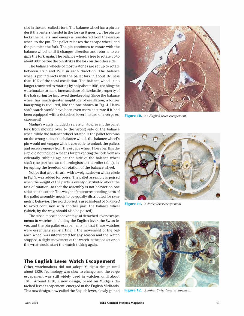
Figure 12. Another Swiss lever escapement.
Figure 11. A Swiss lever escapement.
Figure 10. An English lever escapement.
popularity until the verge escapement was phased outaround 1840.
The English lever incorporated a major improvementover Mudge’s design. To keep the fork away from the bal-ance wheel until the pin returns to engage the fork, force isnecessary to prevent the fork from rotating, keeping it in itsdesired place. Whereas Graham’s pallets had curved lock-ing faces to prevent recoil, the English lever had flat lockingfaces that leaned forward by about 15° to allow the escapewheel to rotate forward by about 1° during lock (see Fig. 10).When the pin (known to horologists as the roller jewel) onthe balance wheel engages the fork to unlock the pallet, theescape wheel must be pushed in the opposite direction(backward), requiring a little extra force to unlock. This ex-tra force is known as draw. You could say that this forceserves to draw the fork away from the balance wheel be-tween engagements. Draw is critical in watch design to en-sure consistent timekeeping, although it was not included inthe early lever designs.
The English lever escapement was used until the end ofwatch production in England, around 1900. This end was
caused by less expensive imports from the United Statesand Switzerland and by the failure of English watchmakersto adapt to changing technologies and markets.
The Swiss LeverThere are two major differences between the Swiss leverand the English lever. As shown in Fig. 11, the axes of rota-tion of the escape wheel, the pallets, and the balance wheelall lie on a straight line. This design feature makes it mucheasier to fabricate this escapement so that it is symmetric. Itis desirable to make the design of the pallets as symmetricalas possible so that the energy the balance wheel receivesfrom the pallet fork would be of the same magnitude for bothdirections. If there was asymmetry, the balance wheelwould rotate more in one direction than the other, whichwould make the timekeeping inconsistent, particularly ifthere was a change in the amplitude of oscillation of the bal-ance wheel, contributing to isochronal error. In theory, theperiod should be the same for all amplitudes. In reality, theperiod decreases slightly as the amplitude increases, caus-ing the watch to gain time. This difference is calledisochronal error: iso meaning “same” and chronos meaning“time.” Isochronal error of balance wheels should not beconfused with the circular error of pendula, caused by gravi-tational forces. Gravitational forces do not affect a properlydesigned balance wheel.
Fig. 12 shows the second major difference between theSwiss and the English lever escapements. The teeth of the es-cape wheel in the English lever are pointed. The escapewheel in the Swiss lever, called the club-tooth escape wheel,has a slope added to the end of each tooth for added strengthand to reduce drop. The ruby pallets are slightly narrower be-cause of this design change, so that the impulse faces of thepallets are shorter. Each escape tooth has an impulse face aswell, however, making the total length of impulse face equalto the sum of both the pallet’s impulse face and the tooth’simpulse face. A reduction in drop increases the transfer of en-ergy from the escape wheel to the balance wheel for everyrevolution of the escape wheel. The Swiss lever escapementis therefore more efficient. The pallet assembly is as light aspossible and is not poised, relying on draw to keep the forkaway from the balance wheel. A very small number ofhigh-grade watches do have poised forks, however.
The Swiss lever design appeared between 1860 and 1870. Ithas been used in virtually all Swiss, American, and Japanesewatches of quality produced since then (probably severalhundred million watches), and it is still being produced today.
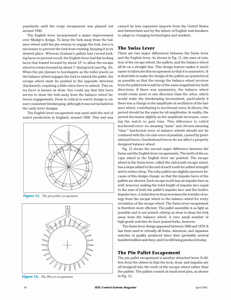
The Pin Pallet EscapementThe pin pallet escapement is another detached lever. It dif-fers from the others in that the lock, draw, and impulse areall designed into the teeth of the escape wheel rather thanthe pallets. The pallets consist of small steel pins, as shownin Fig. 13.
50 IEEE Control Systems Magazine April 2002
Figure 14. The Brocot escapement.
Figure 13. The pin pallet escapement.

The lowest grade pocket watches, such as thedollar watches, and the cheapest clocks, espe-cially alarm clocks, had pin pallet escapements.Again, probably several hundred million time-pieces were produced with several variations ofthis escapement. Some cheap mechanical alarmclocks are still being made with pin pallet escape-ments, using plastic escape wheels and steel pinsin plastic pallet assemblies. Escapements withplastic parts should never be lubricated becausethe lubricants may react with the plastic. Besides,plastics are said to be self-lubricating.
The Brocot EscapementThe Brocot escapement, invented by AchilleBrocot (1817-1878) in Paris around1860, is a pin pallet escapementthat was designed for use with pen-dulum clocks. The teeth of the es-cape wheel do not have drawdesigned into the locking facessince they follow the radial linesfrom the escape wheel’s axis of ro-tation, rather than appearing tolean forward (see Fig. 14). The im-pulse face is designed into the pal-lets rather than the escape teeth,which are pointed. The pin palletsconsist of larger steel pins in theform of a half circle. Some orna-mental clocks have Brocot escape-ments with ruby pins.
A well-adjusted Brocot escape-ment has no recoil, so it is muchmore efficient than a recoil escape-ment. The impulse surfaces of thepin pallets are curved, however, which means that the direc-tion of the force vector, acting to push the pallet, changes asthe escape tooth slides across the impulse face. This es-capement is about 20% less efficient than a similarly propor-tioned Graham escapement, which has straight impulsefaces. To design a similarly proportioned Brocot escape-ment, simply place Brocot pallets over the tips of Grahampallets, as shown in Fig. 15.
This comparison clarifies the similarity between theBrocot and Graham escapements. The escape wheel of theBrocot escapement should have perpendicular teeth ratherthan teeth that appear to lean forward, as in the Graham es-capement.
Other EscapementsEstimates are that several hundred different escapementswere designed in the 18th and 19th centuries. Most were mi-nor variations of the anchor escapements discussed above.There is, however, a different family of escapements that
should be mentioned briefly here. The cylinder,duplex, and chronometer watch escapements dif-fer in that they have no anchors and no pallets.The balance wheel receives energy directly fromthe escape wheel teeth.
By far the most important of these three es-capements is the chronometer. The escape toothprovides energy to the balance wheel while thetooth and the balance wheel’s roller jewel roll to-gether, in the same way the teeth in the gear trainroll together. The direction of the tooth’s and theroller jewel’s force vectors is therefore the sameat the midpoint of their engagement, so the effi-ciency of the energy transfer is nearly 100%. Sincethere is very little friction in this design, no lubri-
cation of the escapement is re-quired, an advantage for improvedtimekeeping.
High-grade marine chronome-ters, based on the chronometer es-capement, have served for over 200years at sea and are still being usedfor ship navigation. Their use hasmore recently decreased becauseof the new satellite navigation sys-tems.
ConclusionsThe influence of the anchor es-capements on horology is enor-mous. As many as 90% of allpendulum clocks produced sinceabout 1660 have had anchor es-capements of the recoil type. Al-though there are dozens ofdifferent styles, the design princi-
ples are essentially the same. Mechanical clocks with re-
April 2002 IEEE Control Systems Magazine 51
Figure 15. Brocot pin pallets over Graham pallets.
The influence of theanchor escapements
on horology isenormous. Nearly
90% of all pendulumclocks produced since1660 have had anchorescapements of the
recoil type.
M.H
EA
DR
ICK

coil escapements are still made today. Almost all finerclocks have been equipped with Graham escapements.
All timepieces with anchor escapements can be seen ashaving three sets of components. There is the driving com-ponent, consisting of a gear train with a source of potentialenergy (gravitational energy with a weight or elastic energywith a mainspring). There is the controlling component,consisting of an anchor and an oscillator, which interactswith the driving component and allows the energy in thedriving component to be expended in a controlled manner.The energy is used to repel the oscillator (the pendulum,balance wheel, or foliot) from its center of oscillation (or itsrest position). The driving component serves to replace en-ergy in the oscillator, energy lost due to friction. The thirdcomponent is the restoring component.
The restoring component consists primarily of an elas-tic spring (suspension spring or hairspring) that stores ki-netic energy from the moving oscillator. The spring causesthe oscillator to decelerate until it stops and then uses thepotential energy to accelerate the oscillator in the oppo-site direction (restoring the oscillator to its center of oscil-lation). Other restoring components include energy fromthe escapement, caused by recoil, and gravitation poten-tial energy.
These three components interact to simulate simple har-monic motion as closely and as predictably as possible,with the objective of measuring the passage of time. Thepassage of time is shown by the rate of descent of the weightor by indicators (the hour, minute, and second hands)mounted onto the shafts of the gears.
The modern watch industry, after being overwhelmed byquartz technology, now produces mechanical watches toserve primarily a luxury market. All new mechanicalwatches, with a few extremely rare exceptions, have Swisslever escapements. Modern methods of production havemade it possible to mass produce these accurate (to withina few seconds per day) and reliable watches with little needfor manual adjustment. The Swiss lever design evolved withthe development of industrial machinery since the Indus-trial Revolution and has recently been optimized with the
application of computer technology and computer-aideddesign programs.
Finally, as mentioned earlier, an escapement mechanismis a speed regulator that uses feedback to obtain precisionoperation despite imperfect components. Detailed analysisof this regulator, from mechanical and control engineeringpoints of view, is incomplete. My hope is that this history ofthe origin and evolution of the anchor escapement will moti-vate continued research into the dynamics and operation ofthese fascinating, ubiquitous, and useful devices.
References[1] A.M. Lepschy, G.A. Mian, and U. Viaro, “Feedback control in ancient waterand mechanical clocks,” IEEE Trans. Educ., vol. 35, no. 1, pp. 3-10, 1992.
[2] A. Roup and D.S. Bernstein, “On the dynamics of the escapement mecha-nism of a mechanical clock,” in Proc. Conf. Decision and Control, Phoenix, AZ,Dec. 1999, pp. 2599-2604.
[3] M.V. Headrick (1997) Clock and Watch Escapement Mechanics [Online].Available: http://www.geocities.com/mvhw/
[4] W.I. Milham, Time and Timekeepers. New York: MacMillan, 1923.
[5] J.E. Haswell, Horology. Wakefield, West Yorkshire, U.K.: E.P. Publishing,1928.
[6] E.J. Tyler, The Craft of the Clockmaker. New York: Crown, 1974.
[7] E.J. Tyler, Clocks and Watches. Berkshire, U.K.: Sampson Low, 1975.
[8] C. Clutton and G. Daniels, Watches. New York: Viking Press, 1965.
[9] E.L. Edwardes, The Story of the Pendulum Clock. Altrincham, U.K.: Sherratt,1977.
[10] F.J. Britten, Britten’s Watch and Clock Maker’s Handbook, Dictionary andGuide, 16th ed. London: Bloomsbury, 1978.
[11] D. Sobel, Longitude. New York: Walker, 1995.
[12] A. Smith, Clocks and Watches. New York: Crescent Books, 1975.
[13] D. de Carle, Watch and Clock Encyclopedia, 3rd ed. Suffolk, U.K.: N.A.G.Press, 1983.
[14] W.L. Goodrich, The Modern Clock. Arlington, VA: Arlington, 1984.
[15] C.M. Cipolla, Clocks and Culture 1300-1700. New York: Norton, 1978.
Mark V. Headrick attended the University of St. Andrews inScotland and the College of William and Mary in Virginia,graduating with a bachelor’s degree in business administra-tion and finance in 1988. He became interested in watchesand clocks while at St. Andrews and has been collecting andrepairing clocks since 1988.
52 IEEE Control Systems Magazine April 2002