tm3 transm receiver guide
TRANSCRIPT

7/23/2019 Tm3 Transm Receiver Guide
http://slidepdf.com/reader/full/tm3-transm-receiver-guide 1/66
E I O 0 0 0 0 0 0 1 4 2 6 . 0
2
www.schneider-electric.com
ModiconTM3
EIO000000142611/2015
Modicon TM3
Transmitter and Receiver ModulesHardware Guide
11/2015
7/23/2019 Tm3 Transm Receiver Guide
http://slidepdf.com/reader/full/tm3-transm-receiver-guide 2/66
2 EIO0000001426 11/2015
The information provided in this documentation contains general descriptions and/or technical
characteristics of the performance of the products contained herein. This documentation is not
intended as a substitute for and is not to be used for determining suitability or reliability of theseproducts for specific user applications. It is the duty of any such user or integrator to perform the
appropriate and complete risk analysis, evaluation and testing of the products with respect to the
relevant specific application or use thereof. Neither Schneider Electric nor any of its affiliates or
subsidiaries shall be responsible or liable for misuse of the information contained herein. If you
have any suggestions for improvements or amendments or have found errors in this publication,
please notify us.
No part of this document may be reproduced in any form or by any means, electronic or
mechanical, including photocopying, without express written permission of Schneider Electric.
All pertinent state, regional, and local safety regulations must be observed when installing and
using this product. For reasons of safety and to help ensure compliance with documented system
data, only the manufacturer should perform repairs to components.
When devices are used for applications with technical safety requirements, the relevant
instructions must be followed.
Failure to use Schneider Electric software or approved software with our hardware products may
result in injury, harm, or improper operating results.Failure to observe this information can result in injury or equipment damage.
© 2015 Schneider Electric. All rights reserved.
7/23/2019 Tm3 Transm Receiver Guide
http://slidepdf.com/reader/full/tm3-transm-receiver-guide 3/66
EIO0000001426 11/2015 3
Table of Contents
Safety Information . . . . . . . . . . . . . . . . . . . . . . . . . . . . . 5
About the Book. . . . . . . . . . . . . . . . . . . . . . . . . . . . . . . . 7
Part I TM3 General Overview. . . . . . . . . . . . . . . . . . . . . . 13Chapter 1 TM3 Description . . . . . . . . . . . . . . . . . . . . . . . . . . . . . . . 15
General Description. . . . . . . . . . . . . . . . . . . . . . . . . . . . . . . . . . . . . . . 15
Chapter 2 TM3 Installation . . . . . . . . . . . . . . . . . . . . . . . . . . . . . . . 192.1 TM3 General Rules for Implementing . . . . . . . . . . . . . . . . . . . . . . . . . 20Environmental Characteristics. . . . . . . . . . . . . . . . . . . . . . . . . . . . . . . 21Certifications and Standards . . . . . . . . . . . . . . . . . . . . . . . . . . . . . . . . 24
2.2 TM3 Expansion Module Installation. . . . . . . . . . . . . . . . . . . . . . . . . . . 25Installation and Maintenance Requirements . . . . . . . . . . . . . . . . . . . . 26Installation Guidelines . . . . . . . . . . . . . . . . . . . . . . . . . . . . . . . . . . . . . 29
Top Hat Section Rail (DIN rail) . . . . . . . . . . . . . . . . . . . . . . . . . . . . . . 30 Assembling a Module to a Controller or Receiver Module . . . . . . . . . 34Disassembling a Module from a Controller or Receiver Module . . . . . 36Direct Mounting on a Panel Surface . . . . . . . . . . . . . . . . . . . . . . . . . . 37
2.3 TM3 Electrical Requirements . . . . . . . . . . . . . . . . . . . . . . . . . . . . . . . 38Wiring Best Practices . . . . . . . . . . . . . . . . . . . . . . . . . . . . . . . . . . . . . 39Grounding the TM3 System. . . . . . . . . . . . . . . . . . . . . . . . . . . . . . . . . 43
Part II TM3 Transmitter and Receiver Modules. . . . . . . . 45Chapter 3 TM3XTRA1 Transmitter Module . . . . . . . . . . . . . . . . . . 47
TM3XTRA1 Presentation. . . . . . . . . . . . . . . . . . . . . . . . . . . . . . . . . . . 48TM3XTRA1 Characteristics . . . . . . . . . . . . . . . . . . . . . . . . . . . . . . . . . 50TM3XTRA1 Wiring Diagram . . . . . . . . . . . . . . . . . . . . . . . . . . . . . . . . 52
Chapter 4 TM3XREC1 Receiver Module. . . . . . . . . . . . . . . . . . . . . 55TM3XREC1 Presentation . . . . . . . . . . . . . . . . . . . . . . . . . . . . . . . . . . 56
TM3XREC1 Characteristics. . . . . . . . . . . . . . . . . . . . . . . . . . . . . . . . . 58TM3XREC1 Wiring Diagram . . . . . . . . . . . . . . . . . . . . . . . . . . . . . . . . 60
Glossary . . . . . . . . . . . . . . . . . . . . . . . . . . . . . . . . . . . . . . . . . 63
Index . . . . . . . . . . . . . . . . . . . . . . . . . . . . . . . . . . . . . . . . . 65

7/23/2019 Tm3 Transm Receiver Guide
http://slidepdf.com/reader/full/tm3-transm-receiver-guide 4/66
4 EIO0000001426 11/2015
7/23/2019 Tm3 Transm Receiver Guide
http://slidepdf.com/reader/full/tm3-transm-receiver-guide 5/66
EIO0000001426 11/2015 5
Safety Information
Important Information
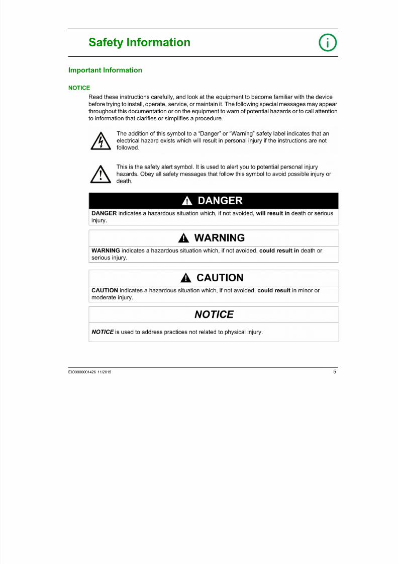
NOTICE
Read these instructions carefully, and look at the equipment to become familiar with the device
before trying to install, operate, service, or maintain it. The following special messages may appear
throughout this documentation or on the equipment to warn of potential hazards or to call attention
to information that clarifies or simplifies a procedure.

7/23/2019 Tm3 Transm Receiver Guide
http://slidepdf.com/reader/full/tm3-transm-receiver-guide 6/66
6 EIO0000001426 11/2015
PLEASE NOTE
Electrical equipment should be installed, operated, serviced, and maintained only by qualified
personnel. No responsibility is assumed by Schneider Electric for any consequences arising out ofthe use of this material.
A qualified person is one who has skills and knowledge related to the construction and operation
of electrical equipment and its installation, and has received safety training to recognize and avoid
the hazards involved.
7/23/2019 Tm3 Transm Receiver Guide
http://slidepdf.com/reader/full/tm3-transm-receiver-guide 7/66
EIO0000001426 11/2015 7
About the Book
At a Glance
Document Scope
This guide describes the hardware implementation of TM3 Transmitter and Receiver modules. It
provides the part description, characteristics, wiring diagrams, and installation details for TM3
Transmitter and Receiver modules.
Validity Note
This document has been updated for the release of SoMachine V4.1 SP2.
This document has been updated for the release of SoMachine Basic V1.4.
For product compliance and environmental information (RoHS, REACh, PEP, EOLI, etc.), go to
www.schneider-electric.com/green-premium.
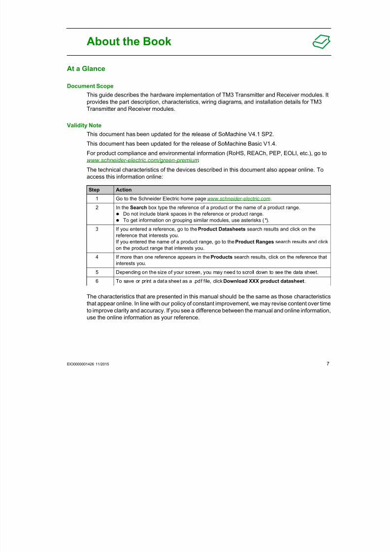
The technical characteristics of the devices described in this document also appear online. Toaccess this information online:
The characteristics that are presented in this manual should be the same as those characteristics
that appear online. In line with our policy of constant improvement, we may revise content over time
to improve clarity and accuracy. If you see a difference between the manual and online information,
use the online information as your reference.
Step Action
1 Go to the Schneider Electric home page www.schneider-electric.com.
2 In the Search box type the reference of a product or the name of a product range.
Do not include blank spaces in the reference or product range.
To get information on grouping similar modules, use asterisks ( * ).
3 If you entered a reference, go to the Product Datasheets search results and click on thereference that interests you.
If you entered the name of a product range, go to the Product Ranges search results and click
on the product range that interests you.
4 If more than one reference appears in the Products search results, click on the reference that
interests you.
5 Depending on the size of your screen, you may need to scroll down to see the data sheet.
6 To save or print a data sheet as a .pdf file, click Download XXX product datasheet.
7/23/2019 Tm3 Transm Receiver Guide
http://slidepdf.com/reader/full/tm3-transm-receiver-guide 8/66
8 EIO0000001426 11/2015
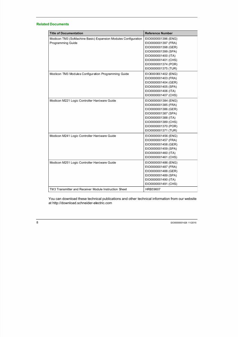
Related Documents
You can download these technical publications and other technical information from our website
at http://download.schneider-electric.com
Title of Documentation Reference Number
Modicon TM3 (SoMachine Basic) Expansion Modules Configuration
Programming Guide
EIO0000001396 (ENG)
EIO0000001397 (FRA)
EIO0000001398 (GER)
EIO0000001399 (SPA)
EIO0000001400 (ITA)
EIO0000001401 (CHS)
EIO0000001374 (POR)
EIO0000001375 (TUR)Modicon TM3 Modules Configuration Programming Guide EIO0000001402 (ENG)
EIO0000001403 (FRA)
EIO0000001404 (GER)
EIO0000001405 (SPA)
EIO0000001406 (ITA)
EIO0000001407 (CHS)
Modicon M221 Logic Controller Hardware Guide EIO0000001384 (ENG)
EIO0000001385 (FRA)EIO0000001386 (GER)
EIO0000001387 (SPA)
EIO0000001388 (ITA)
EIO0000001389 (CHS)
EIO0000001370 (POR)
EIO0000001371 (TUR)
Modicon M241 Logic Controller Hardware Guide EIO0000001456 (ENG)
EIO0000001457 (FRA)EIO0000001458 (GER)
EIO0000001459 (SPA)
EIO0000001460 (ITA)
EIO0000001461 (CHS)
Modicon M251 Logic Controller Hardware Guide EIO0000001486 (ENG)
EIO0000001487 (FRA)
EIO0000001488 (GER)
EIO0000001489 (SPA)
EIO0000001490 (ITA)
EIO0000001491 (CHS)
TM3 Transmitter and Receiver Module Instruction Sheet HRB59607
7/23/2019 Tm3 Transm Receiver Guide
http://slidepdf.com/reader/full/tm3-transm-receiver-guide 9/66
EIO0000001426 11/2015 9
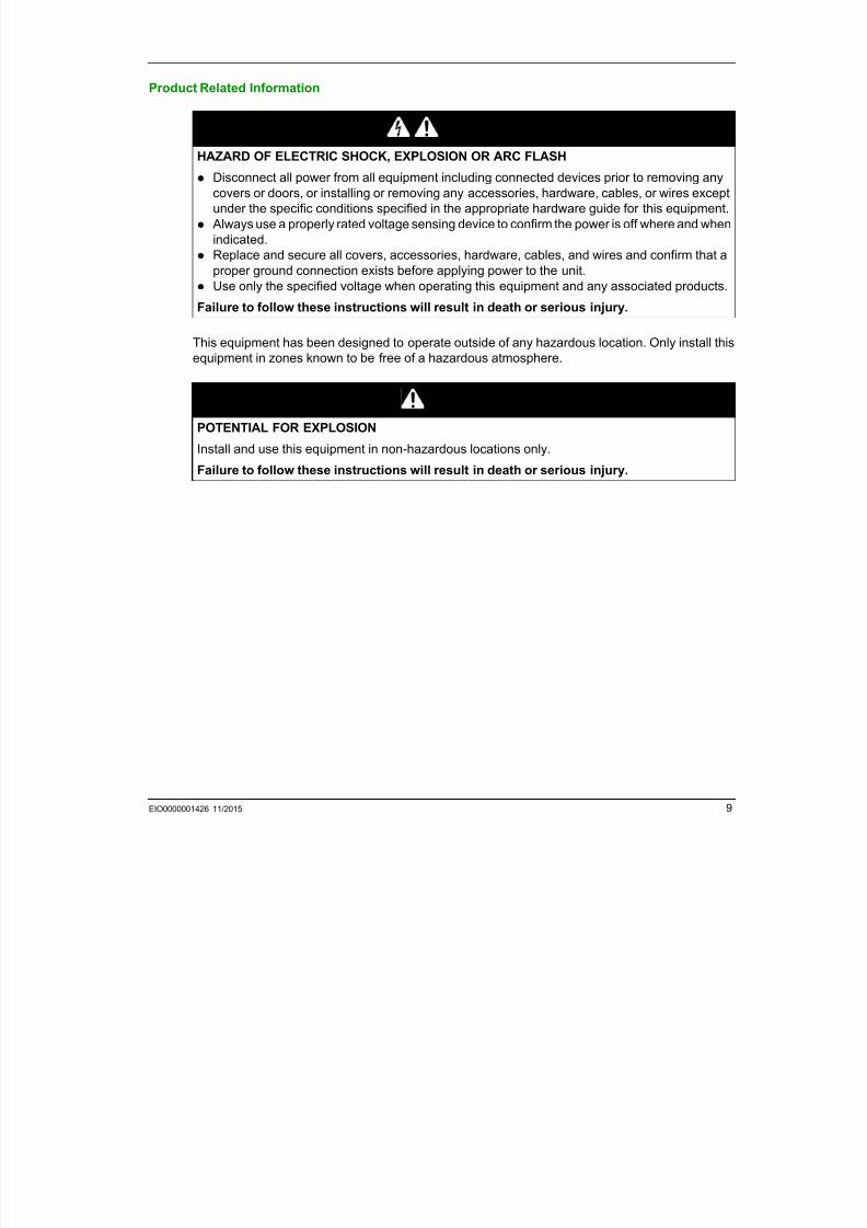
Product Related Information
This equipment has been designed to operate outside of any hazardous location. Only install this
equipment in zones known to be free of a hazardous atmosphere.
DANGERHAZARD OF ELECTRIC SHOCK, EXPLOSION OR ARC FLASH
Disconnect all power from all equipment including connected devices prior to removing any
covers or doors, or installing or removing any accessories, hardware, cables, or wires except
under the specific conditions specified in the appropriate hardware guide for this equipment.
Always use a properly rated voltage sensing device to confirm the power is off where and when
indicated.
Replace and secure all covers, accessories, hardware, cables, and wires and confirm that aproper ground connection exists before applying power to the unit.
Use only the specified voltage when operating this equipment and any associated products.
Failure to follow these instructions will result in death or serious injury.
DANGERPOTENTIAL FOR EXPLOSION
Install and use this equipment in non-hazardous locations only.
Failure to follow these instructions will result in death or serious injury.
7/23/2019 Tm3 Transm Receiver Guide
http://slidepdf.com/reader/full/tm3-transm-receiver-guide 10/66
10 EIO0000001426 11/2015
1
For additional information, refer to NEMA ICS 1.1 (latest edition), "Safety Guidelines for the Application, Installation, and Maintenance of Solid State Control" and to NEMA ICS 7.1 (latest
edition), "Safety Standards for Construction and Guide for Selection, Installation and Operation of
Adjustable-Speed Drive Systems" or their equivalent governing your particular location.
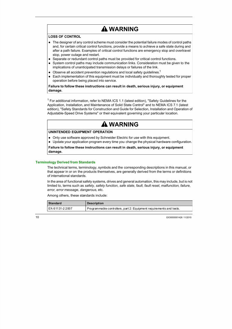
Terminology Derived from Standards
The technical terms, terminology, symbols and the corresponding descriptions in this manual, or
that appear in or on the products themselves, are generally derived from the terms or definitionsof international standards.
In the area of functional safety systems, drives and general automation, this may include, but is not
limited to, terms such as safety , safety function, safe state, fault , fault reset , malfunction, failure,
error , error message, dangerous, etc.
Among others, these standards include:
WARNINGLOSS OF CONTROL
The designer of any control scheme must consider the potential failure modes of control paths
and, for certain critical control functions, provide a means to achieve a safe state during and
after a path failure. Examples of critical control functions are emergency stop and overtravel
stop, power outage and restart.
Separate or redundant control paths must be provided for critical control functions.
System control paths may include communication links. Consideration must be given to the
implications of unanticipated transmission delays or failures of the link. Observe all accident prevention regulations and local safety guidelines.1
Each implementation of this equipment must be individually and thoroughly tested for proper
operation before being placed into service.
Failure to follow these instructions can result in death, serious injury, or equipment
damage.
WARNINGUNINTENDED EQUIPMENT OPERATION
Only use software approved by Schneider Electric for use with this equipment. Update your application program every time you change the physical hardware configuration.
Failure to follow these instructions can result in death, serious injury, or equipment
damage.
Standard DescriptionEN 61131-2:2007 Programmable controllers, part 2: Equipment requirements and tests.
7/23/2019 Tm3 Transm Receiver Guide
http://slidepdf.com/reader/full/tm3-transm-receiver-guide 11/66
EIO0000001426 11/2015 11
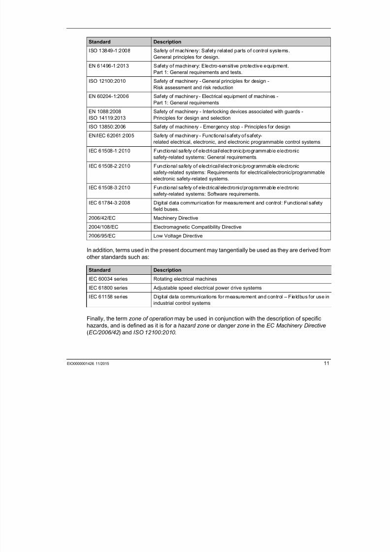
In addition, terms used in the present document may tangentially be used as they are derived from
other standards such as:
Finally, the term zone of operation may be used in conjunction with the description of specific
hazards, and is defined as it is for a hazard zone or danger zone in the EC Machinery Directive
(EC/2006/42 ) and ISO 12100:2010 .
ISO 13849-1:2008 Safety of machinery: Safety related parts of control systems.
General principles for design.
EN 61496-1:2013 Safety of machinery: Electro-sensitive protective equipment.
Part 1: General requirements and tests.
ISO 12100:2010 Safety of machinery - General principles for design -
Risk assessment and risk reduction
EN 60204-1:2006 Safety of machinery - Electrical equipment of machines -
Part 1: General requirements
EN 1088:2008
ISO 14119:2013
Safety of machinery - Interlocking devices associated with guards -
Principles for design and selection
ISO 13850:2006 Safety of machinery - Emergency stop - Principles for design
EN/IEC 62061:2005 Safety of machinery - Functional safety of safety-
related electrical, electronic, and electronic programmable control systems
IEC 61508-1:2010 Functional safety of electrical/electronic/programmable electronic
safety-related systems: General requirements.
IEC 61508-2:2010 Functional safety of electrical/electronic/programmable electronic
safety-related systems: Requirements for electrical/electronic/programmableelectronic safety-related systems.
IEC 61508-3:2010 Functional safety of electrical/electronic/programmable electronic
safety-related systems: Software requirements.
IEC 61784-3:2008 Digital data communication for measurement and control: Functional safety
field buses.
2006/42/EC Machinery Directive
2004/108/EC Electromagnetic Compatibility Directive2006/95/EC Low Voltage Directive
Standard Description
IEC 60034 series Rotating electrical machines
IEC 61800 series Adjustable speed electrical power drive systems
IEC 61158 series Digital data communications for measurement and control – Fieldbus for use in
industrial control systems
Standard Description

7/23/2019 Tm3 Transm Receiver Guide
http://slidepdf.com/reader/full/tm3-transm-receiver-guide 12/66
12 EIO0000001426 11/2015
NOTE: The aforementioned standards may or may not apply to the specific products cited in the
present documentation. For more information concerning the individual standards applicable to the
products described herein, see the characteristics tables for those product references.
ModiconTM3
TM3 General Overview

7/23/2019 Tm3 Transm Receiver Guide
http://slidepdf.com/reader/full/tm3-transm-receiver-guide 13/66
EIO0000001426 11/2015 13
EIO0000001426 11/2015
TM3 General Overview
Part I
TM3 General Overview
What Is in This Part?
This part contains the following chapters:
Chapter Chapter Name Page
1 TM3 Description 15
2 TM3 Installation 19

7/23/2019 Tm3 Transm Receiver Guide
http://slidepdf.com/reader/full/tm3-transm-receiver-guide 14/66
TM3 General Overview
14 EIO0000001426 11/2015
ModiconTM3
TM3 Description
EIO000000142611/2015
7/23/2019 Tm3 Transm Receiver Guide
http://slidepdf.com/reader/full/tm3-transm-receiver-guide 15/66
EIO0000001426 11/2015 15
EIO0000001426 11/2015
TM3 Description
Chapter 1
TM3 Description
General Description
Introduction
The TM3 transmitter expansion module is equipped with:
1 front connector RJ45 1 screw for functional ground connection
2 status LEDs (link and power)
The TM3 receiver expansion module is equipped with:
1 front connector RJ45
1 connector for power supply
2 status LEDs (link and power)
The TM3 transmitter module is connected to the logic controller through the TM3 bus. It isconnected using a connector at the left side of the module. The TM3 transmitter expansion module
is the last physical module of the local configuration (there is no bus connector on the right-hand
side of the module).
The TM3 receiver module is connected through the front connector RJ45 to the TM3 transmitter
module with an appropriate cable ( see page 17 ).
TM3 Transmitter and Receiver Modules
The following table shows the TM3 transmitter and receiver expansion modules:
Reference Description Terminal Type / Pitch
TM3XTRA1 ( see page 47 ) Data transmitter module for remote I/O 1 front connector RJ-45
1 screw for functional ground
connection
TM3XREC1 ( see page 55 ) Data receiver module for remote I/O 1 front connector RJ-45
Power supply connector / 5.08 mm
7/23/2019 Tm3 Transm Receiver Guide
http://slidepdf.com/reader/full/tm3-transm-receiver-guide 16/66
TM3 Description
16 EIO0000001426 11/2015
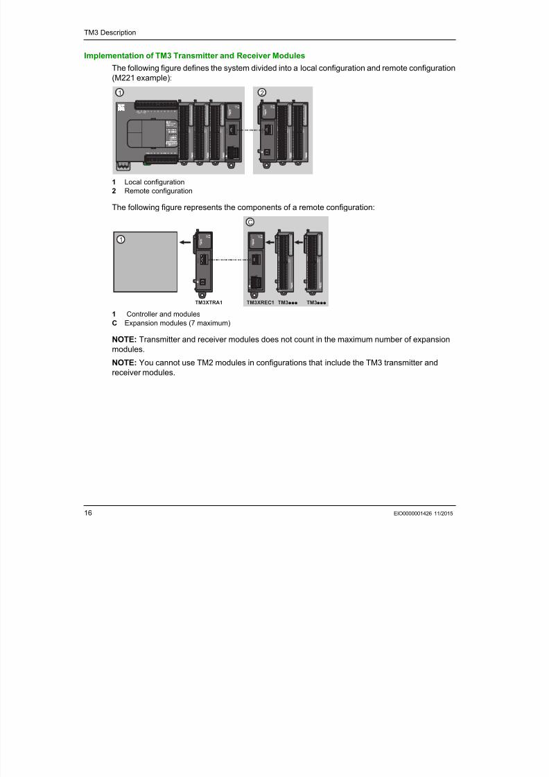
Implementation of TM3 Transmitter and Receiver Modules
The following figure defines the system divided into a local configuration and remote configuration
(M221 example):
1 Local configuration
2 Remote configuration
The following figure represents the components of a remote configuration:
1 Controller and modules
C Expansion modules (7 maximum)
NOTE: Transmitter and receiver modules does not count in the maximum number of expansion
modules.
NOTE: You cannot use TM2 modules in configurations that include the TM3 transmitter and
receiver modules.
21
0 1 2 3 4 5 6
0 1 2 3 4 5 6
7 8
Bus Receiver
CN2
T M 3 C O M
T M 3 X R E C 1
CN1
0 V
2 4 V c
Bus Transmitter
T M 3 C O M
T M 3 X T R A 1
CN1
Bus Receiver
CN2
T M 3 C O M
T M 3 X R E C 1
CN1
0 V
2 4 V c
Bus Transmitter
T M 3 C O M
T M 3 X T R A 1
CN1
C
TM3pppTM3XTRA1 TM3XREC1 TM3ppp
1
7/23/2019 Tm3 Transm Receiver Guide
http://slidepdf.com/reader/full/tm3-transm-receiver-guide 17/66
TM3 Description
EIO0000001426 11/2015 17
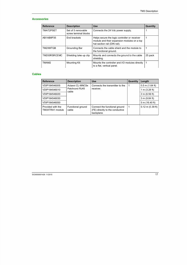
Accessories
Cables
Reference Description Use Quantity
TMAT2PSET Set of 5 removable
screw terminal blocks
Connects the 24 Vdc power supply. 1
AB1AB8P35 End brackets Helps secure the logic controller or receiver
module and their expansion modules on a top
hat section rail (DIN rail).
1
TM2XMTGB Grounding Bar Connects the cable shield and the module to
the functional ground.
1
TM200RSRCEMC Shielding take-up clip Mounts and connects the ground to the cableshielding.
25 pack
TMAM2 Mounting Kit Mounts the controller and I/O modules directly
to a flat, vertical panel.
1
Reference Description Use Quantity Length
VDIP184546005 Actassi CL-MNC5e
Patchcord RJ45
cable
Connects the transmitter to the
receiver.
1 0.5 m (1.64 ft)
VDIP184546010 1 m (3.28 ft)
VDIP184546020 2 m (6.56 ft)
VDIP184546030 3 m (9.84 ft)
VDIP184546050 5 m (16.40 ft)
Provided with the
TM3XTRA1 module
Functional ground
cable
Connect the functional ground
(FE) directly to the conductivebackplane.
1 0.12 m (0.39 ft)

7/23/2019 Tm3 Transm Receiver Guide
http://slidepdf.com/reader/full/tm3-transm-receiver-guide 18/66
TM3 Description
18 EIO0000001426 11/2015
ModiconTM3
TM3 Installation
EIO0000001426 11/2015
7/23/2019 Tm3 Transm Receiver Guide
http://slidepdf.com/reader/full/tm3-transm-receiver-guide 19/66
EIO0000001426 11/2015 19
TM3 Installation
Chapter 2
TM3 Installation
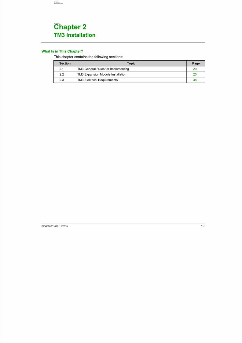
What Is in This Chapter?
This chapter contains the following sections:
Section Topic Page
2.1 TM3 General Rules for Implementing 20
2.2 TM3 Expansion Module Installation 25
2.3 TM3 Electrical Requirements 38
7/23/2019 Tm3 Transm Receiver Guide
http://slidepdf.com/reader/full/tm3-transm-receiver-guide 20/66
TM3 Installation
20 EIO0000001426 11/2015
TM3 General Rules for Implementing
Section 2.1
TM3 General Rules for Implementing
What Is in This Section?
This section contains the following topics:
Topic Page
Environmental Characteristics 21
Certifications and Standards 24
7/23/2019 Tm3 Transm Receiver Guide
http://slidepdf.com/reader/full/tm3-transm-receiver-guide 21/66
TM3 Installation
EIO0000001426 11/2015 21
Environmental Characteristics
Enclosure RequirementsTM3 expansion module components are designed as Zone B, Class A industrial equipment
according to IEC/CISPR Publication 11. If they are used in environments other than those
described in these standards, or in environments that do not meet the specifications in this manual
the ability to meet electromagnetic compatibility requirements in the presence of conducted and/or
radiated interference may be reduced.
All TM3 expansion module components meet European Community (CE) requirements for open
equipment as defined by IEC/EN 61131-2. You must install them in an enclosure designed for the
specific environmental conditions and to minimize the possibility of unintended contact with
hazardous voltages. Use metal enclosures to improve the electromagnetic immunity of your TM3
expansion module components. Use enclosures with a keyed locking mechanism to minimize
unauthorized access.
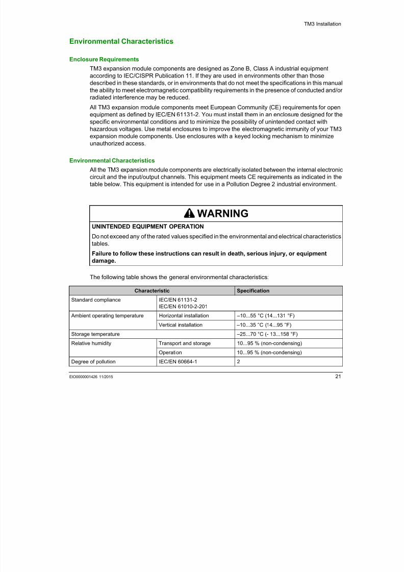
Environmental Characteristics
All the TM3 expansion module components are electrically isolated between the internal electronic
circuit and the input/output channels. This equipment meets CE requirements as indicated in thetable below. This equipment is intended for use in a Pollution Degree 2 industrial environment.
The following table shows the general environmental characteristics:
WARNINGUNINTENDED EQUIPMENT OPERATION
Do not exceed any of the rated values specified in the environmental and electrical characteristicstables.
Failure to follow these instructions can result in death, serious injury, or equipment
damage.
Characteristic Specification
Standard compliance IEC/EN 61131-2
IEC/EN 61010-2-201
Ambient operating temperature Horizontal installation –10...55 °C (14...131 °F)
Vertical installation –10...35 °C (14...95 °F)
Storage temperature –25...70 °C (- 13...158 °F)
Relative humidity Transport and storage 10...95 % (non-condensing)
Operation 10...95 % (non-condensing)
Degree of pollution IEC/EN 60664-1 2
7/23/2019 Tm3 Transm Receiver Guide
http://slidepdf.com/reader/full/tm3-transm-receiver-guide 22/66
TM3 Installation
22 EIO0000001426 11/2015
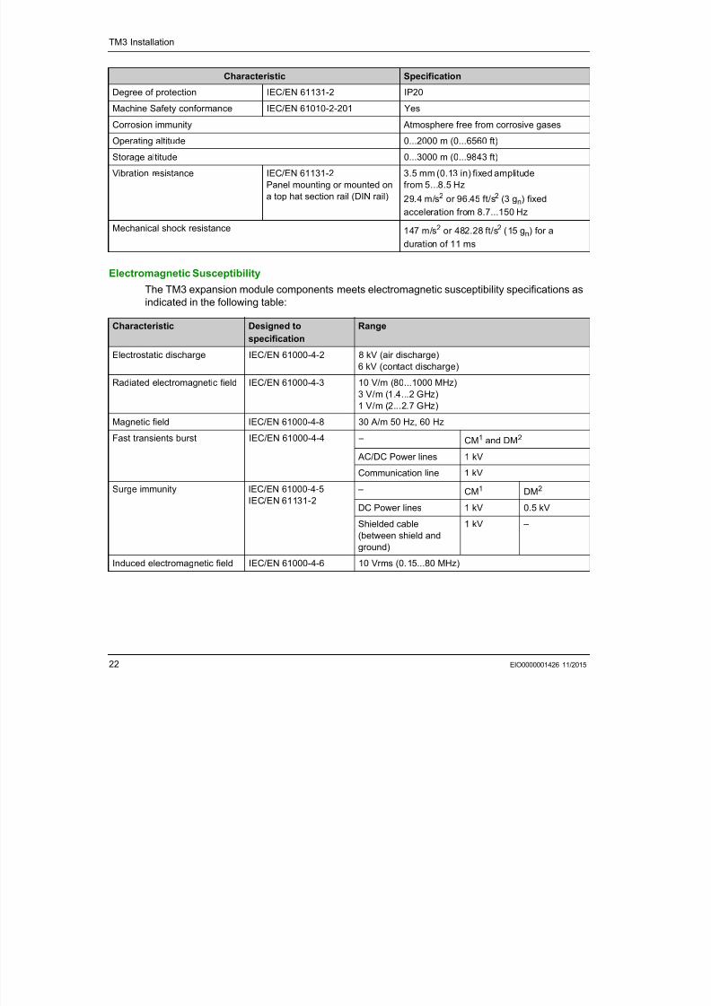
Electromagnetic Susceptibility
The TM3 expansion module components meets electromagnetic susceptibility specifications as
indicated in the following table:
Degree of protection IEC/EN 61131-2 IP20
Machine Safety conformance IEC/EN 61010-2-201 Yes
Corrosion immunity Atmosphere free from corrosive gases
Operating altitude 0...2000 m (0...6560 ft)
Storage altitude 0...3000 m (0...9843 ft)
Vibration resistance IEC/EN 61131-2
Panel mounting or mounted on
a top hat section rail (DIN rail)
3.5 mm (0.13 in) fixed amplitude
from 5...8.5 Hz
29.4 m/s2 or 96.45 ft/s2 (3 gn) fixed
acceleration from 8.7...150 Hz
Mechanical shock resistance 147 m/s2 or 482.28 ft/s2 (15 gn) for a
duration of 11 ms
Characteristic Specification
Characteristic Designed to
specification
Range
Electrostatic discharge IEC/EN 61000-4-2 8 kV (air discharge)
6 kV (contact discharge)
Radiated electromagnetic field IEC/EN 61000-4-3 10 V/m (80...1000 MHz)
3 V/m (1.4...2 GHz)
1 V/m (2...2.7 GHz)
Magnetic field IEC/EN 61000-4-8 30 A/m 50 Hz, 60 Hz
Fast transients burst IEC/EN 61000-4-4 – CM1 and DM2
AC/DC Power lines 1 kV
Communication line 1 kV
Surge immunity IEC/EN 61000-4-5
IEC/EN 61131-2
– CM1 DM2
DC Power lines 1 kV 0.5 kV
Shielded cable(between shield and
ground)
1 kV –
Induced electromagnetic field IEC/EN 61000-4-6 10 Vrms (0.15...80 MHz)
7/23/2019 Tm3 Transm Receiver Guide
http://slidepdf.com/reader/full/tm3-transm-receiver-guide 23/66
TM3 Installation
EIO0000001426 11/2015 23
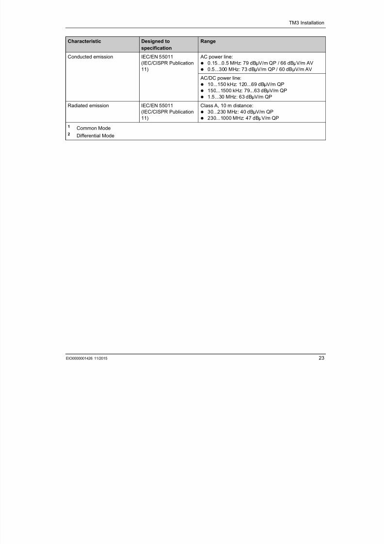
Conducted emission IEC/EN 55011(IEC/CISPR Publication
11)
AC power line: 0.15...0.5 MHz: 79 dBμV/m QP / 66 dBμV/m AV
0.5...300 MHz: 73 dBμV/m QP / 60 dBµV/m AV
AC/DC power line:
10...150 kHz: 120...69 dBμV/m QP
150...1500 kHz: 79...63 dBμV/m QP
1.5...30 MHz: 63 dBμV/m QP
Radiated emission IEC/EN 55011
(IEC/CISPR Publication11)
Class A, 10 m distance:
30...230 MHz: 40 dBμV/m QP
230...1000 MHz: 47 dBμV/m QP
1 Common Mode2 Differential Mode
Characteristic Designed to
specification
Range
7/23/2019 Tm3 Transm Receiver Guide
http://slidepdf.com/reader/full/tm3-transm-receiver-guide 24/66
TM3 Installation
24 EIO0000001426 11/2015
Certifications and Standards
IntroductionThe TM3 expansion modules are designed to conform to the main national and international
standards concerning electronic industrial control devices:
IEC/EN 61131-2
UL 508
The TM3 have obtained the following conformity marks:
CE
UL/CSA
EAC RCM
cCSAus Hazardous Location
The TM3 expansion modules comply with the main national and international Directives and
Regulations concerning electronic industrial control devices:
REACh v9
Europe RoHS:
Exemption annex III 7(a)
Exemption annex III 7(c)-I
Exemption annex III 34
China RoHS regulations
7/23/2019 Tm3 Transm Receiver Guide
http://slidepdf.com/reader/full/tm3-transm-receiver-guide 25/66
TM3 Installation
EIO0000001426 11/2015 25
TM3 Expansion ModuleInstallation
Section 2.2
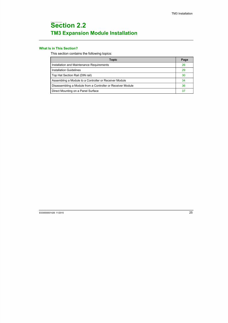
TM3 Expansion Module Installation
What Is in This Section?
This section contains the following topics:
Topic Page
Installation and Maintenance Requirements 26
Installation Guidelines 29
Top Hat Section Rail (DIN rail) 30
Assembling a Module to a Controller or Receiver Module 34
Disassembling a Module from a Controller or Receiver Module 36
Direct Mounting on a Panel Surface 37
7/23/2019 Tm3 Transm Receiver Guide
http://slidepdf.com/reader/full/tm3-transm-receiver-guide 26/66
TM3 Installation
26 EIO0000001426 11/2015
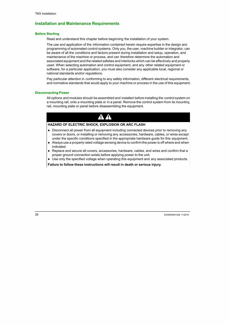
Installation and Maintenance Requirements
Before StartingRead and understand this chapter before beginning the installation of your system.
The use and application of the information contained herein require expertise in the design and
programming of automated control systems. Only you, the user, machine builder or integrator, can
be aware of all the conditions and factors present during installation and setup, operation, and
maintenance of the machine or process, and can therefore determine the automation and
associated equipment and the related safeties and interlocks which can be effectively and properly
used. When selecting automation and control equipment, and any other related equipment or
software, for a particular application, you must also consider any applicable local, regional ornational standards and/or regulations.
Pay particular attention in conforming to any safety information, different electrical requirements,
and normative standards that would apply to your machine or process in the use of this equipment.
Disconnecting Power
All options and modules should be assembled and installed before installing the control system on
a mounting rail, onto a mounting plate or in a panel. Remove the control system from its mountingrail, mounting plate or panel before disassembling the equipment.
DANGERHAZARD OF ELECTRIC SHOCK, EXPLOSION OR ARC FLASH
Disconnect all power from all equipment including connected devices prior to removing any
covers or doors, or installing or removing any accessories, hardware, cables, or wires exceptunder the specific conditions specified in the appropriate hardware guide for this equipment.
Always use a properly rated voltage sensing device to confirm the power is off where and when
indicated.
Replace and secure all covers, accessories, hardware, cables, and wires and confirm that a
proper ground connection exists before applying power to the unit.
Use only the specified voltage when operating this equipment and any associated products.
Failure to follow these instructions will result in death or serious injury.
7/23/2019 Tm3 Transm Receiver Guide
http://slidepdf.com/reader/full/tm3-transm-receiver-guide 27/66
TM3 Installation
EIO0000001426 11/2015 27
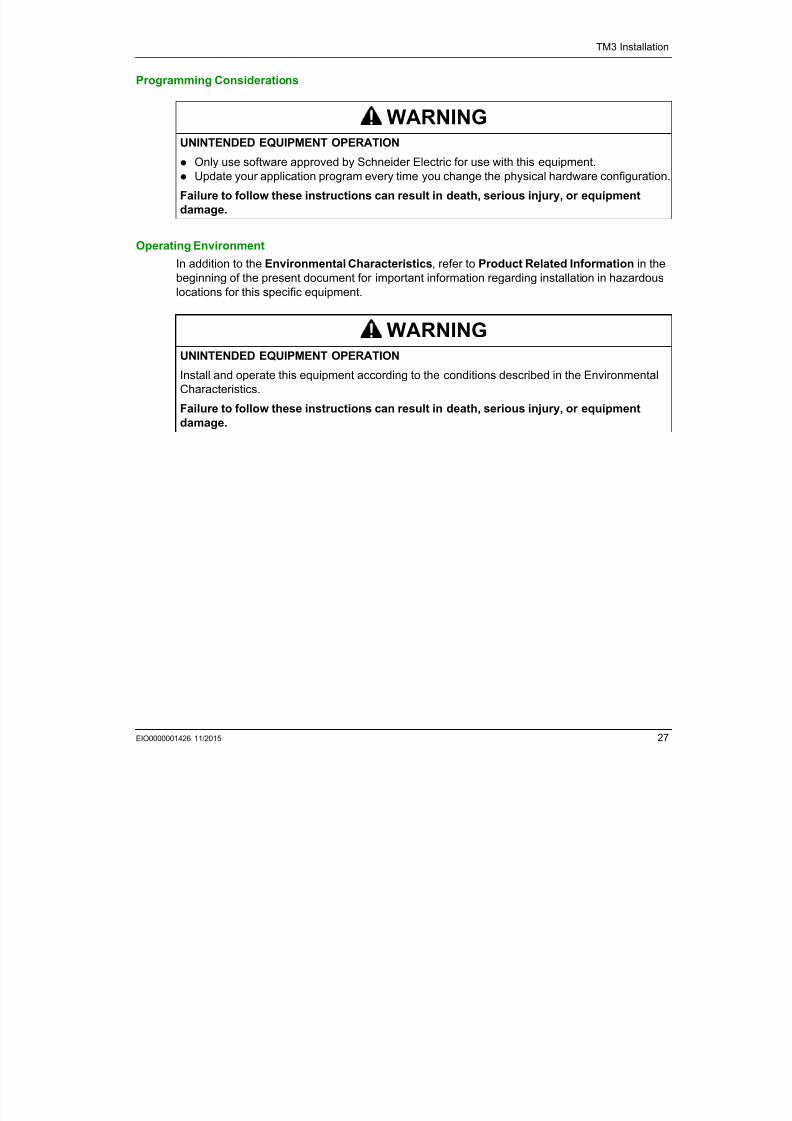
Programming Considerations
Operating Environment
In addition to the Environmental Characteristics, refer to Product Related Information in the
beginning of the present document for important information regarding installation in hazardous
locations for this specific equipment.
WARNINGUNINTENDED EQUIPMENT OPERATION
Only use software approved by Schneider Electric for use with this equipment.
Update your application program every time you change the physical hardware configuration.
Failure to follow these instructions can result in death, serious injury, or equipment
damage.
WARNINGUNINTENDED EQUIPMENT OPERATION
Install and operate this equipment according to the conditions described in the Environmental
Characteristics.
Failure to follow these instructions can result in death, serious injury, or equipment
damage.
7/23/2019 Tm3 Transm Receiver Guide
http://slidepdf.com/reader/full/tm3-transm-receiver-guide 28/66
TM3 Installation
28 EIO0000001426 11/2015
Installation Considerations
NOTE: JDYX2 or JDYX8 fuse types are UL-recognized and CSA approved.
WARNINGUNINTENDED EQUIPMENT OPERATION
Use appropriate safety interlocks where personnel and/or equipment hazards exist.
Install and operate this equipment in an enclosure appropriately rated for its intended
environment.
Use the sensor and actuator power supplies only for supplying power to the sensors or
actuators connected to the module.
Power line and output circuits must be wired and fused in compliance with local and nationalregulatory requirements for the rated current and voltage of the particular equipment.
Do not use this equipment in safety-critical machine functions unless the equipment is
otherwise designated as functional safety equipment and conforming to applicable regulations
and standards.
Do not disassemble, repair, or modify this equipment.
Do not connect any wiring to reserved, unused connections, or to connections designated as
No Connection (N.C.).
Failure to follow these instructions can result in death, serious injury, or equipmentdamage.
7/23/2019 Tm3 Transm Receiver Guide
http://slidepdf.com/reader/full/tm3-transm-receiver-guide 29/66
TM3 Installation
EIO0000001426 11/2015 29
Installation Guidelines
IntroductionTM3 expansion modules are assembled by connecting them to a logic controller or receiver
module.
The logic controller or receiver module and their expansion modules can be installed on a top hat
section rail (DIN rail).
Mounting Position and Minimum Clearances
The mounting position and minimum clearances of the expansion modules must conform with therules defined for the appropriate hardware system. Refer to the Installation chapter in the Controller
Hardware documentation for your specific controller.
WARNINGUNINTENDED EQUIPMENT OPERATION
Place devices dissipating the most heat at the top of the cabinet and ensure adequate
ventilation.
Avoid placing this equipment next to or above devices that might cause overheating.
Install the equipment in a location providing the minimum clearances from all adjacent
structures and equipment as directed in this document.
Install all equipment in accordance with the specifications in the related documentation.
Failure to follow these instructions can result in death, serious injury, or equipment
damage.
7/23/2019 Tm3 Transm Receiver Guide
http://slidepdf.com/reader/full/tm3-transm-receiver-guide 30/66
TM3 Installation
30 EIO0000001426 11/2015
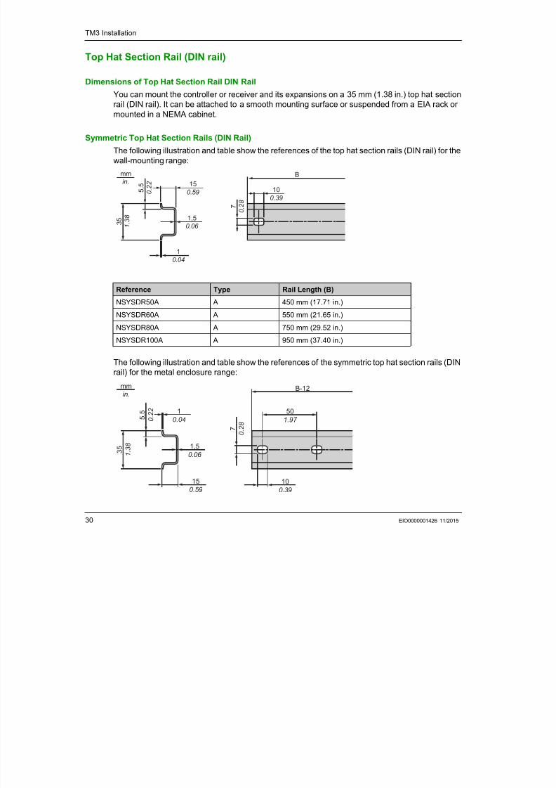
Top Hat Section Rail (DIN rail)
Dimensions of Top Hat Section Rail DIN RailYou can mount the controller or receiver and its expansions on a 35 mm (1.38 in.) top hat section
rail (DIN rail). It can be attached to a smooth mounting surface or suspended from a EIA rack or
mounted in a NEMA cabinet.
Symmetric Top Hat Section Rails (DIN Rail)
The following illustration and table show the references of the top hat section rails (DIN rail) for the
wall-mounting range:
The following illustration and table show the references of the symmetric top hat section rails (DIN
rail) for the metal enclosure range:
Reference Type Rail Length (B)
NSYSDR50A A 450 mm (17.71 in.)
NSYSDR60A A 550 mm (21.65 in.)
NSYSDR80A A 750 mm (29.52 in.)
NSYSDR100A A 950 mm (37.40 in.)
5 , 5
0 . 2
2
1,5
0.06 3 5
1 . 3
8
15
0.59
1
0.04
7 0 . 2
8
10
0.39
Bmm
in.
5 , 5 0 .
2 2
1,5
0.06 3 5
1 . 3
8
501.97
B-12
7 0 .
2 8
10.04
15
0.59
10
0.39
mm
in.
7/23/2019 Tm3 Transm Receiver Guide
http://slidepdf.com/reader/full/tm3-transm-receiver-guide 31/66
TM3 Installation
EIO0000001426 11/2015 31
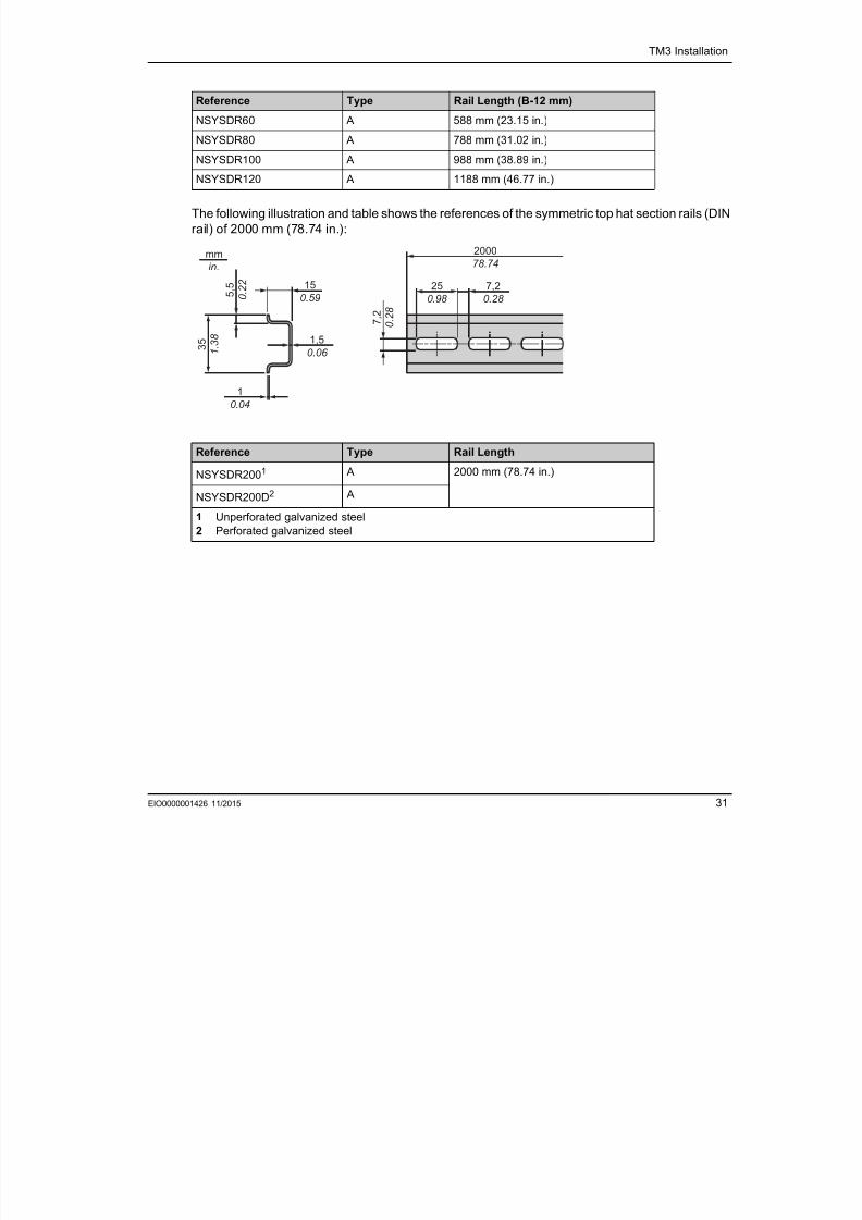
The following illustration and table shows the references of the symmetric top hat section rails (DIN
rail) of 2000 mm (78.74 in.):
Reference Type Rail Length (B-12 mm)
NSYSDR60 A 588 mm (23.15 in.)
NSYSDR80 A 788 mm (31.02 in.)
NSYSDR100 A 988 mm (38.89 in.)
NSYSDR120 A 1188 mm (46.77 in.)
Reference Type Rail Length
NSYSDR2001 A 2000 mm (78.74 in.)
NSYSDR200D2 A
1 Unperforated galvanized steel
2 Perforated galvanized steel
1
0.04
2000
78.74
3 5
1 . 3
8
5 , 5
0 . 2
2
7 , 2
0 . 2
8
15
0.59
1,5
0.06
25
0.98
7,2
0.28
mmin.
7/23/2019 Tm3 Transm Receiver Guide
http://slidepdf.com/reader/full/tm3-transm-receiver-guide 32/66
TM3 Installation
32 EIO0000001426 11/2015
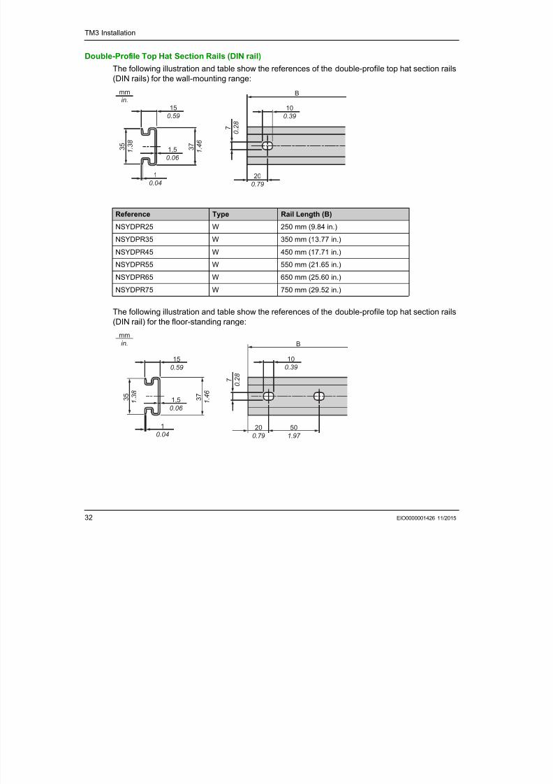
Double-Profile Top Hat Section Rails (DIN rail)
The following illustration and table show the references of the double-profile top hat section rails
(DIN rails) for the wall-mounting range:
The following illustration and table show the references of the double-profile top hat section rails
(DIN rail) for the floor-standing range:
Reference Type Rail Length (B)
NSYDPR25 W 250 mm (9.84 in.)
NSYDPR35 W 350 mm (13.77 in.)
NSYDPR45 W 450 mm (17.71 in.)
NSYDPR55 W 550 mm (21.65 in.)
NSYDPR65 W 650 mm (25.60 in.)
NSYDPR75 W 750 mm (29.52 in.)
B
10
0.39
20
0.79
7 0 . 2
8
15
0.59
3 7
1 . 4
6
1
0.04
3 5
1 . 3
8
mm
in.
1,5
0.06
B
10
0.39
50
1.97
20
0.79
7 0 . 2
8
1,5
0.06
15
0.59
3 5
1 . 3
8
3 7
1 . 4
6
1
0.04
mm
in.

7/23/2019 Tm3 Transm Receiver Guide
http://slidepdf.com/reader/full/tm3-transm-receiver-guide 33/66
TM3 Installation
EIO0000001426 11/2015 33
Reference Type Rail Length (B)
NSYDPR60 F 588 mm (23.15 in.)
NSYDPR80 F 788 mm (31.02 in.)
NSYDPR100 F 988 mm (38.89 in.)
NSYDPR120 F 1188 mm (46.77 in.)
7/23/2019 Tm3 Transm Receiver Guide
http://slidepdf.com/reader/full/tm3-transm-receiver-guide 34/66
TM3 Installation
34 EIO0000001426 11/2015
Assembling a Module to a Controller or Receiver Module
IntroductionThis section describes how to assemble an expansion module to a controller, Receiver module or
other modules.
After connecting new modules to the controller, either directly or through a transmitter/receiver,
update and redownload your application program before placing the system back in service. If you
do not revise your application program to reflect the addition of new modules, I/O located on the
expansion bus may no longer operate normally.
DANGERHAZARD OF ELECTRIC SHOCK, EXPLOSION OR ARC FLASH
Disconnect all power from all equipment including connected devices prior to removing anycovers or doors, or installing or removing any accessories, hardware, cables, or wires except
under the specific conditions specified in the appropriate hardware guide for this equipment.
Always use a properly rated voltage sensing device to confirm the power is off where and when
indicated.
Replace and secure all covers, accessories, hardware, cables, and wires and confirm that a
proper ground connection exists before applying power to the unit.
Use only the specified voltage when operating this equipment and any associated products.
Failure to follow these instructions will result in death or serious injury.
WARNINGUNINTENDED EQUIPMENT OPERATION
Only use software approved by Schneider Electric for use with this equipment.
Update your application program every time you change the physical hardware configuration.
Failure to follow these instructions can result in death, serious injury, or equipment
damage.
7/23/2019 Tm3 Transm Receiver Guide
http://slidepdf.com/reader/full/tm3-transm-receiver-guide 35/66
TM3 Installation
EIO0000001426 11/2015 35
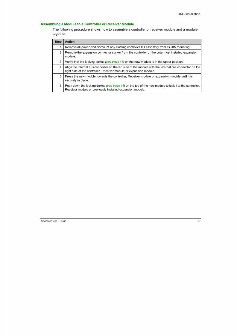
Assembling a Module to a Controller or Receiver Module
The following procedure shows how to assemble a controller or receiver module and a module
together.
Step Action
1 Remove all power and dismount any existing controller I/O assembly from its DIN mounting.
2 Remove the expansion connector sticker from the controller or the outermost installed expansion
module.
3 Verify that the locking device ( see page 48 ) on the new module is in the upper position.
4 Align the internal bus connector on the left side of the module with the internal bus connector on the
right side of the controller, Receiver module or expansion module.
5 Press the new module towards the controller, Receiver module or expansion module until it is
securely in place.
6 Push down the locking device ( see page 48 ) on the top of the new module to lock it to the controller,
Receiver module or previously installed expansion module.
7/23/2019 Tm3 Transm Receiver Guide
http://slidepdf.com/reader/full/tm3-transm-receiver-guide 36/66
TM3 Installation
36 EIO0000001426 11/2015
Disassembling a Module from a Controller or Receiver Module
IntroductionThis section describes how to disassemble a module from a controller or receiver module.
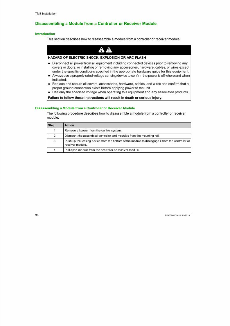
Disassembling a Module from a Controller or Receiver Module
The following procedure describes how to disassemble a module from a controller or receiver
module.
DANGERHAZARD OF ELECTRIC SHOCK, EXPLOSION OR ARC FLASH
Disconnect all power from all equipment including connected devices prior to removing any
covers or doors, or installing or removing any accessories, hardware, cables, or wires exceptunder the specific conditions specified in the appropriate hardware guide for this equipment.
Always use a properly rated voltage sensing device to confirm the power is off where and when
indicated.
Replace and secure all covers, accessories, hardware, cables, and wires and confirm that a
proper ground connection exists before applying power to the unit.
Use only the specified voltage when operating this equipment and any associated products.
Failure to follow these instructions will result in death or serious injury.
Step Action
1 Remove all power from the control system.
2 Dismount the assembled controller and modules from the mounting rail.3 Push up the locking device from the bottom of the module to disengage it from the controller or
receiver module.
4 Pull apart module from the controller or receiver module.
7/23/2019 Tm3 Transm Receiver Guide
http://slidepdf.com/reader/full/tm3-transm-receiver-guide 37/66
TM3 Installation
EIO0000001426 11/2015 37
Direct Mounting on a Panel Surface
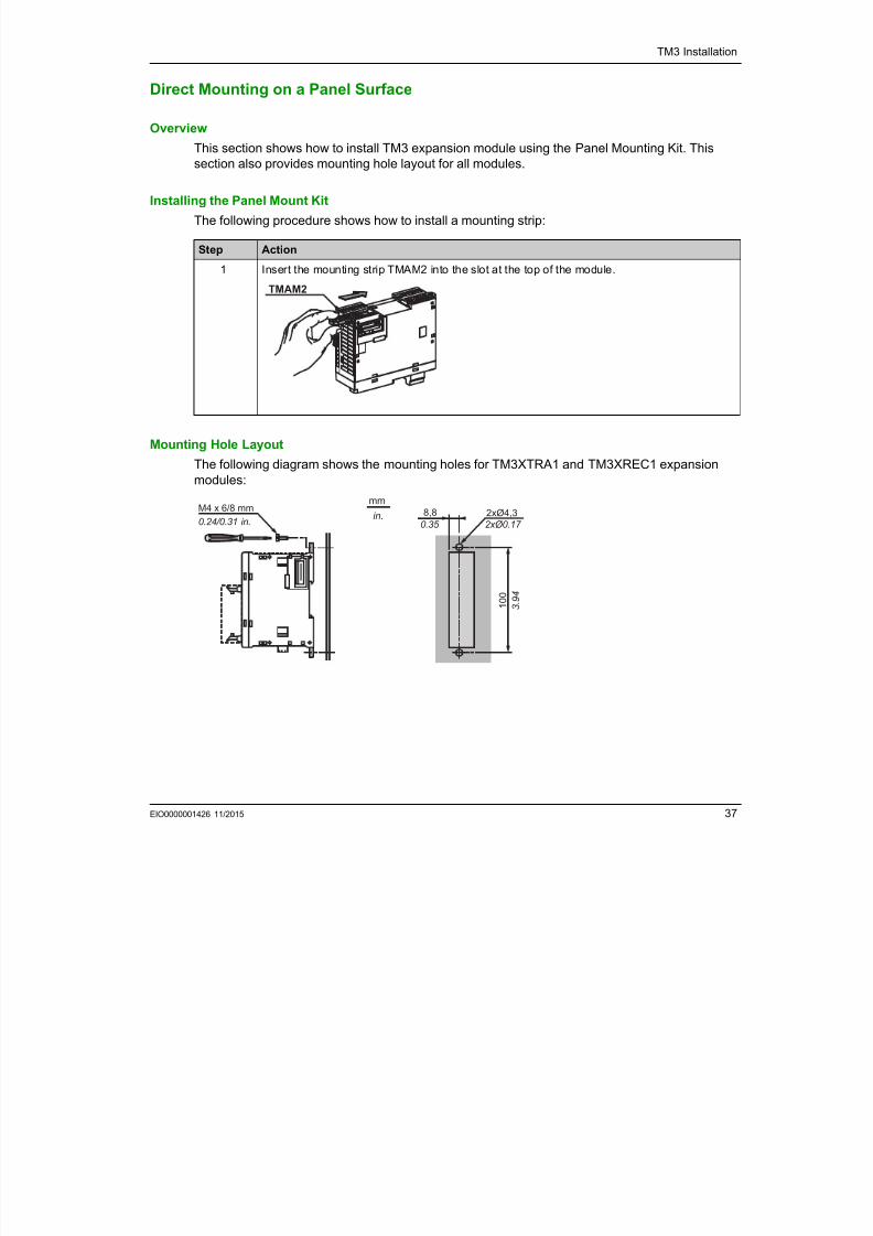
OverviewThis section shows how to install TM3 expansion module using the Panel Mounting Kit. This
section also provides mounting hole layout for all modules.
Installing the Panel Mount Kit
The following procedure shows how to install a mounting strip:
Mounting Hole Layout
The following diagram shows the mounting holes for TM3XTRA1 and TM3XREC1 expansion
modules:
Step Action
1 Insert the mounting strip TMAM2 into the slot at the top of the module.
TMAM2
M4 x 6/8 mm
0.24/0.31 in. 8,80.35 2xØ4,32xØ0.17
1 0 0
3 . 9
4
mm
in.
7/23/2019 Tm3 Transm Receiver Guide
http://slidepdf.com/reader/full/tm3-transm-receiver-guide 38/66
TM3 Installation
38 EIO0000001426 11/2015
TM3 ElectricalRequirements
Section 2.3
TM3 Electrical Requirements
What Is in This Section?
This section contains the following topics:
Topic Page
Wiring Best Practices 39
Grounding the TM3 System 43
7/23/2019 Tm3 Transm Receiver Guide
http://slidepdf.com/reader/full/tm3-transm-receiver-guide 39/66
TM3 Installation
EIO0000001426 11/2015 39
Wiring Best Practices
OverviewThis section describes the wiring guidelines and associated best practices to be respected when
using the TM3 system.
1 For additional information, refer to NEMA ICS 1.1 (latest edition), "Safety Guidelines for the
Application, Installation, and Maintenance of Solid State Control" and to NEMA ICS 7.1 (latest
edition), "Safety Standards for Construction and Guide for Selection, Installation and Operation of
Adjustable-Speed Drive Systems" or their equivalent governing your particular location.
DANGERHAZARD OF ELECTRIC SHOCK, EXPLOSION OR ARC FLASH
Disconnect all power from all equipment including connected devices prior to removing anycovers or doors, or installing or removing any accessories, hardware, cables, or wires except
under the specific conditions specified in the appropriate hardware guide for this equipment.
Always use a properly rated voltage sensing device to confirm the power is off where and when
indicated.
Replace and secure all covers, accessories, hardware, cables, and wires and confirm that a
proper ground connection exists before applying power to the unit.
Use only the specified voltage when operating this equipment and any associated products.
Failure to follow these instructions will result in death or serious injury.
WARNINGLOSS OF CONTROL
The designer of any control scheme must consider the potential failure modes of control paths
and, for certain critical control functions, provide a means to achieve a safe state during and
after a path failure. Examples of critical control functions are emergency stop and overtravel
stop, power outage and restart.
Separate or redundant control paths must be provided for critical control functions.
System control paths may include communication links. Consideration must be given to the
implications of unanticipated transmission delays or failures of the link.
Observe all accident prevention regulations and local safety guidelines.1
Each implementation of this equipment must be individually and thoroughly tested for proper
operation before being placed into service.
Failure to follow these instructions can result in death, serious injury, or equipment
damage.
7/23/2019 Tm3 Transm Receiver Guide
http://slidepdf.com/reader/full/tm3-transm-receiver-guide 40/66
TM3 Installation
40 EIO0000001426 11/2015
Functional Ground (FE) on the DIN Rail
The DIN Rail for your TM3 system is common with the functional ground (FE) plane and must be
mounted on a conductive backplane.
Protective Ground (PE) on the Backplane
The protective ground (PE) is connected to the conductive backplane by a heavyduty wire, usually
a braided copper cable with the maximum allowable cable section.
Wiring Guidelines
The following rules must be applied when wiring a TM3 system: I/O and communication wiring must be kept separate from the power wiring. Route these 2 types
of wiring in separate cable ducting.
Verify that the operating conditions and environment are within the specification values.
Use proper wire sizes to meet voltage and current requirements.
Use copper conductors.
Use twisted-pair, shielded cables for analog, and/or fast I/O.
Use twisted-pair, shielded cables for networks, and field bus.
1Multipoint grounding is permissible if connections are made to an equipotential ground plane
dimensioned to help avoid cable shield damage in the event of power system short-circuit currents.
NOTE: Surface temperatures may exceed 60° C. To conform to IEC 61010 standards, route
primary wiring (wires connected to power mains) separately and apart from secondary wiring (extra
low voltage wiring coming from intervening power sources). If that is not possible, double insulation
is required such as conduit or cable gains.
WARNINGUNINTENDED EQUIPMENT OPERATION
Connect the DIN rail to the functional ground (FE) of your installation.
Failure to follow these instructions can result in death, serious injury, or equipment
damage.
WARNINGUNINTENDED EQUIPMENT OPERATION
Use shielded cables for all fast I/O, analog I/O, and communication signals.
Ground cable shields for all fast I/O, analog I/O, and communication signals at a single point1.
Route communications and I/O cables separately from power cables.
Failure to follow these instructions can result in death, serious injury, or equipmentdamage.
7/23/2019 Tm3 Transm Receiver Guide
http://slidepdf.com/reader/full/tm3-transm-receiver-guide 41/66
TM3 Installation
EIO0000001426 11/2015 41
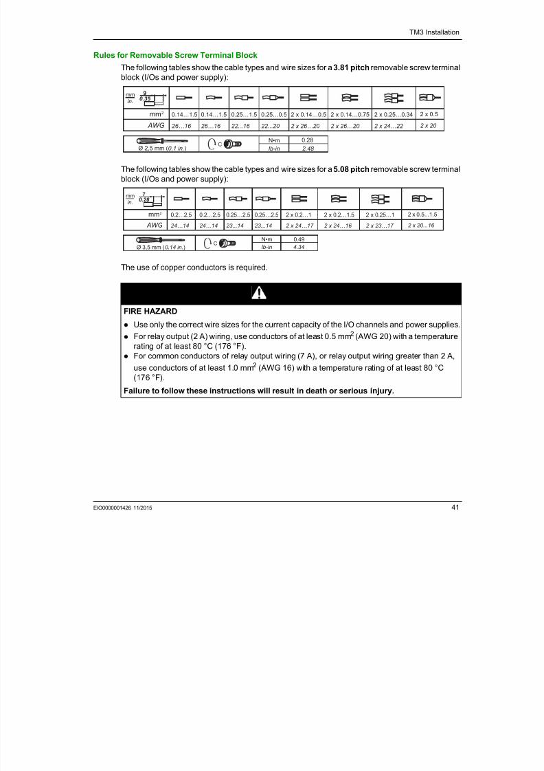
Rules for Removable Screw Terminal Block
The following tables show the cable types and wire sizes for a 3.81 pitch removable screw terminal
block (I/Os and power supply):
The following tables show the cable types and wire sizes for a 5.08 pitch removable screw terminal
block (I/Os and power supply):
The use of copper conductors is required.
DANGERFIRE HAZARD
Use only the correct wire sizes for the current capacity of the I/O channels and power supplies.
For relay output (2 A) wiring, use conductors of at least 0.5 mm2 (AWG 20) with a temperature
rating of at least 80 °C (176 °F).
For common conductors of relay output wiring (7 A), or relay output wiring greater than 2 A,
use conductors of at least 1.0 mm2 (AWG 16) with a temperature rating of at least 80 °C
(176 °F).
Failure to follow these instructions will result in death or serious injury.
Ø 2,5 mm (0.1 in.)
mm2
AWG
0.14…1.5
26…16
0.14…1.5
26…16
0.25…1.5
22...16
2 x 0.25…0.34
2 x 24…22
2 x 0.14…0.75
2 x 26…20
2 x 0.14…0.5
2 x 26…20
2 x 0.5
2 x 20
mm
in.
9
0.35
C0.28
2.48
lb-in
0.25…0.5
22...20
Ø 3,5 mm (0.14 in.)
mm2
AWG
0.2…2.5
24…14
0.2…2.5
24…14
0.25…2.5
23...14
2 x 0.25…1
2 x 23…17
2 x 0.2…1.5
2 x 24…16
2 x 0.2…1
2 x 24…17
2 x 0.5...1.5
2 x 20...16
mm
in.
7
0.28
C
lb-in
0.25…2.5
23...14
0.49
4.34
7/23/2019 Tm3 Transm Receiver Guide
http://slidepdf.com/reader/full/tm3-transm-receiver-guide 42/66
TM3 Installation
42 EIO0000001426 11/2015
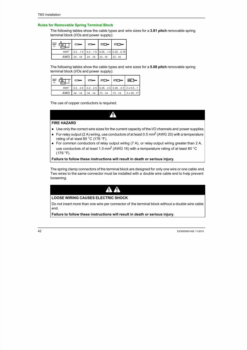
Rules for Removable Spring Terminal Block
The following tables show the cable types and wire sizes for a 3.81 pitch removable spring
terminal block (I/Os and power supply):
The following tables show the cable types and wire sizes for a 5.08 pitch removable spring
terminal block (I/Os and power supply):
The use of copper conductors is required.
The spring clamp connectors of the terminal block are designed for only one wire or one cable end.
Two wires to the same connector must be installed with a double wire cable end to help prevent
loosening.
DANGERFIRE HAZARD
Use only the correct wire sizes for the current capacity of the I/O channels and power supplies.
For relay output (2 A) wiring, use conductors of at least 0.5 mm2 (AWG 20) with a temperature
rating of at least 80 °C (176 °F).
For common conductors of relay output wiring (7 A), or relay output wiring greater than 2 A,
use conductors of at least 1.0 mm2 (AWG 16) with a temperature rating of at least 80 °C
(176 °F).
Failure to follow these instructions will result in death or serious injury.
DANGERLOOSE WIRING CAUSES ELECTRIC SHOCK
Do not insert more than one wire per connector of the terminal block without a double wire cable
end.
Failure to follow these instructions will result in death or serious injury.
mm2
AWG
0.2…1.5
24…16
0.2…1.5
24…16
0.25…1.5
23...16
mm
in.
9
0.35
0.25…0.75
23...19
mm2
AWG
0.2…2.5
24…14
0.2…2.5
24…14
0.25…2.5
23...14
mm
in.
10
0.39
0.25…2.5
23...14
2 x 0.5...1
2 x 20...17
7/23/2019 Tm3 Transm Receiver Guide
http://slidepdf.com/reader/full/tm3-transm-receiver-guide 43/66
TM3 Installation
EIO0000001426 11/2015 43
Grounding the TM3 System
OverviewThe effects of electromagnetic interference, cables carrying fast I/O, analog I/O, and the fieldbus
communication signals must be shielded.
1Multipoint grounding is permissible if connections are made to an equipotential ground plane
dimensioned to help avoid cable shield damage in the event of power system short-circuit currents.
The use of shielded cables requires compliance with the following wiring rules:
For protective earth ground connections (PE), metal conduit or ducting can be used for part of
the shielding length, provided there is no break in the continuity of the ground connections. For
functional ground (FE), the shielding is intended to attenuate electromagnetic interference and
the shielding must be continuous for the length of the cable. If the purpose is both functional and
protective, as is often the case for communication cables, the cable must have continuous
shielding.
Wherever possible, keep cables carrying one type of signal separate from the cables carryingother types of signals or power.
Protective Earth Ground (PE) on the Backplane
The protective earth ground (PE) is connected to the conductive backplane by a heavy-duty wire,
usually a braided copper cable with the maximum allowable cable section.
Shielded Cables Connections
Cables carrying fast I/O, analog I/O, and the fieldbus communication signals must be shielded. The
shielding must be securely connected to ground. Fast I/O and analog I/O shields may be
connected either to the functional ground (FE) or to the protective earth ground (PE) of your TM3
expansion module. The fieldbus communication cable shields must be connected to the protective
earth ground (PE) with a connecting clamp secured to the conductive backplane of your
installation.
WARNINGUNINTENDED EQUIPMENT OPERATION
Use shielded cables for all fast I/O, analog I/O, and communication signals. Ground cable shields for all fast I/O, analog I/O, and communication signals at a single point1.
Route communications and I/O cables separately from power cables.
Failure to follow these instructions can result in death, serious injury, or equipment
damage.
7/23/2019 Tm3 Transm Receiver Guide
http://slidepdf.com/reader/full/tm3-transm-receiver-guide 44/66
TM3 Installation
44 EIO0000001426 11/2015
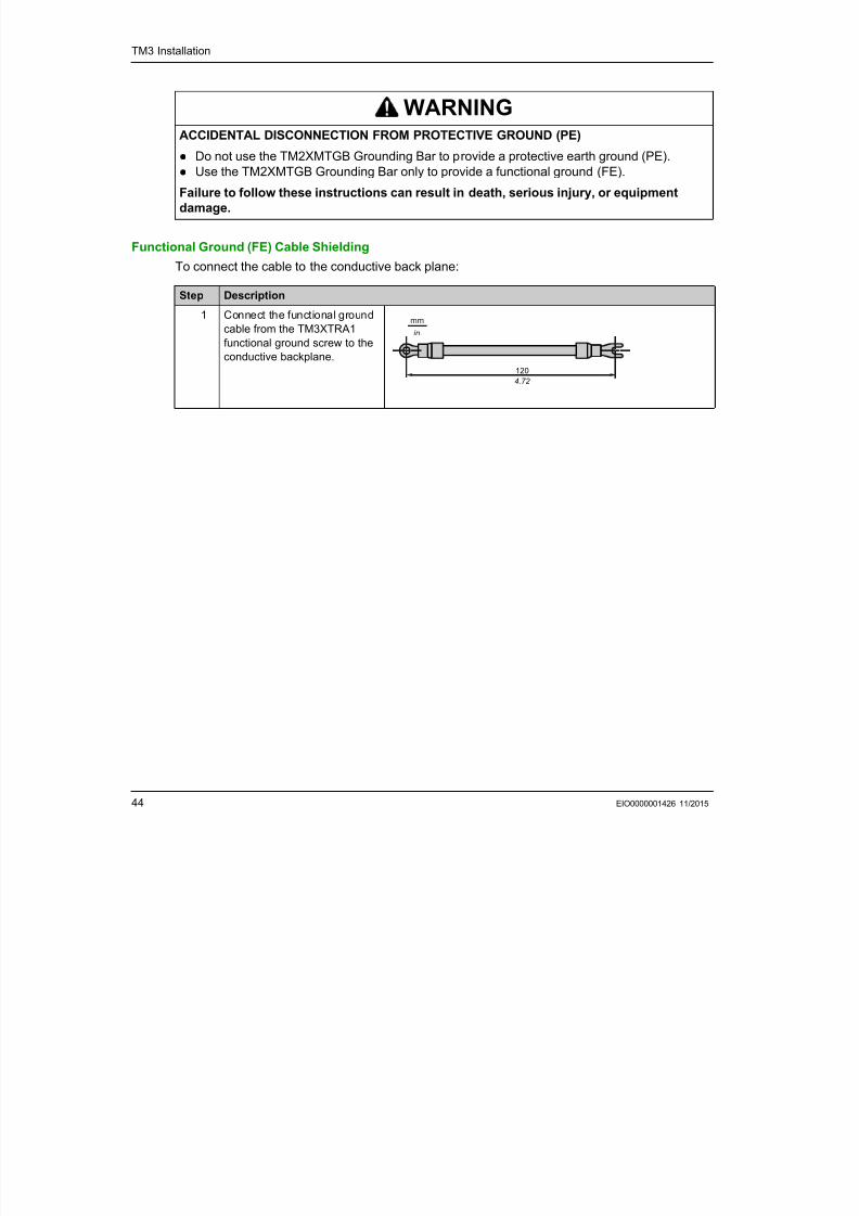
Functional Ground (FE) Cable Shielding
To connect the cable to the conductive back plane:
WARNING
ACCIDENTAL DISCONNECTION FROM PROTECTIVE GROUND (PE)
Do not use the TM2XMTGB Grounding Bar to provide a protective earth ground (PE).
Use the TM2XMTGB Grounding Bar only to provide a functional ground (FE).
Failure to follow these instructions can result in death, serious injury, or equipment
damage.
Step Description
1 Connect the functional ground
cable from the TM3XTRA1
functional ground screw to the
conductive backplane.
mm
in.
120
4.72
ModiconTM3
TM3 Transmitter andReceiver Modules
EIO0000001426 11/2015
7/23/2019 Tm3 Transm Receiver Guide
http://slidepdf.com/reader/full/tm3-transm-receiver-guide 45/66
EIO0000001426 11/2015 45
TM3 Transmitter andReceiver Modules
Part II
TM3 Transmitter and Receiver Modules
What Is in This Part?
This part contains the following chapters:
Chapter Chapter Name Page
3 TM3XTRA1 Transmitter Module 47
4 TM3XREC1 Receiver Module 55

7/23/2019 Tm3 Transm Receiver Guide
http://slidepdf.com/reader/full/tm3-transm-receiver-guide 46/66
TM3 Transmitter and Receiver Modules
46 EIO0000001426 11/2015
ModiconTM3
TM3XTRA1Transmitter Module
EIO0000001426 11/2015

7/23/2019 Tm3 Transm Receiver Guide
http://slidepdf.com/reader/full/tm3-transm-receiver-guide 47/66
EIO0000001426 11/2015 47
TM3XTRA1Transmitter Module
Chapter 3
TM3XTRA1 Transmitter Module
Overview
This chapter describes the TM3XTRA1 expansion module, its characteristics, and its connection
to the different sensors.
What Is in This Chapter?This chapter contains the following topics:
Topic Page
TM3XTRA1 Presentation 48
TM3XTRA1 Characteristics 50
TM3XTRA1 Wiring Diagram 52
TM3XTRA1 T itt M d l
7/23/2019 Tm3 Transm Receiver Guide
http://slidepdf.com/reader/full/tm3-transm-receiver-guide 48/66
TM3XTRA1 Transmitter Module
48 EIO0000001426 11/2015
TM3XTRA1 Presentation
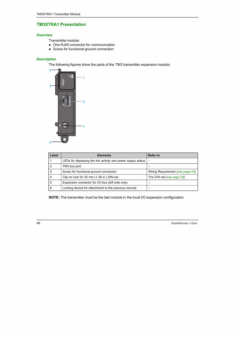
OverviewTransmitter module:
One RJ45 connector for communication
Screw for functional ground connection
Description
The following figures show the parts of the TM3 transmitter expansion module:
NOTE: The transmitter must be the last module in the local I/O expansion configuration.
Label Elements Refer to
1 LEDs for displaying the link activity and power supply status. –
2 TM3 bus port –
3 Screw for functional ground connection Wiring Requirement ( see page 43 )
4 Clip-on lock for 35 mm (1.38 in.) DIN-rail The DIN rail ( see page 30 )
5 Expansion connector for I/O bus (left side only). –
6 Locking device for attachment to the previous module –
Bus Transmitter
T M 3 C O M
T M 3 X T R A 1
CN1
1
5
6
4
3
2
TM3XTRA1 Transmitter Module
7/23/2019 Tm3 Transm Receiver Guide
http://slidepdf.com/reader/full/tm3-transm-receiver-guide 49/66
TM3XTRA1 Transmitter Module
EIO0000001426 11/2015 49
Status LEDs
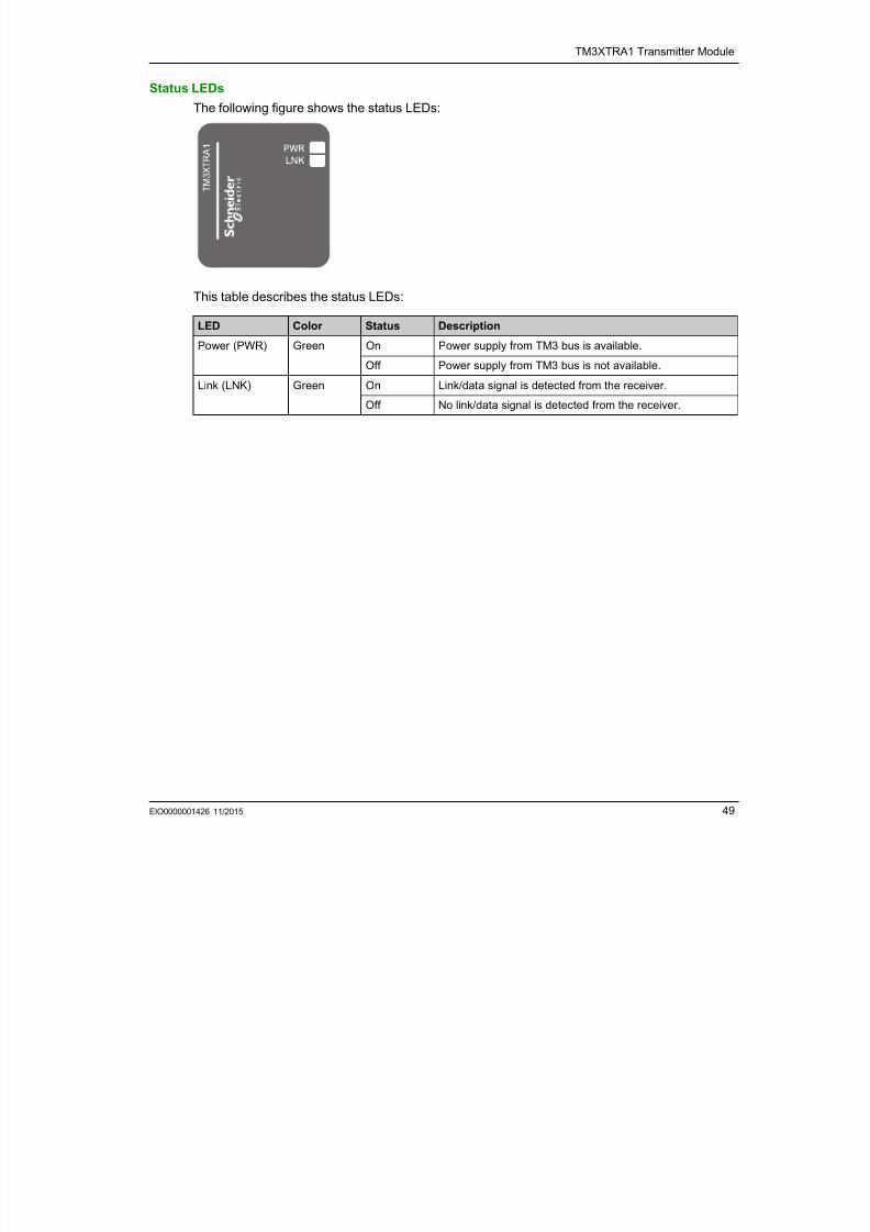
The following figure shows the status LEDs:
This table describes the status LEDs:
LED Color Status Description
Power (PWR) Green On Power supply from TM3 bus is available.
Off Power supply from TM3 bus is not available.
Link (LNK) Green On Link/data signal is detected from the receiver.Off No link/data signal is detected from the receiver.
TM3XTRA1 Transmitter Module
7/23/2019 Tm3 Transm Receiver Guide
http://slidepdf.com/reader/full/tm3-transm-receiver-guide 50/66
TM3XTRA1 Transmitter Module
50 EIO0000001426 11/2015
TM3XTRA1 Characteristics
Introduction
This section provides a description of the characteristics of the TM3XTRA1 expansion module.
See also Environmental Characteristics ( see page 21 ).
Dimensions
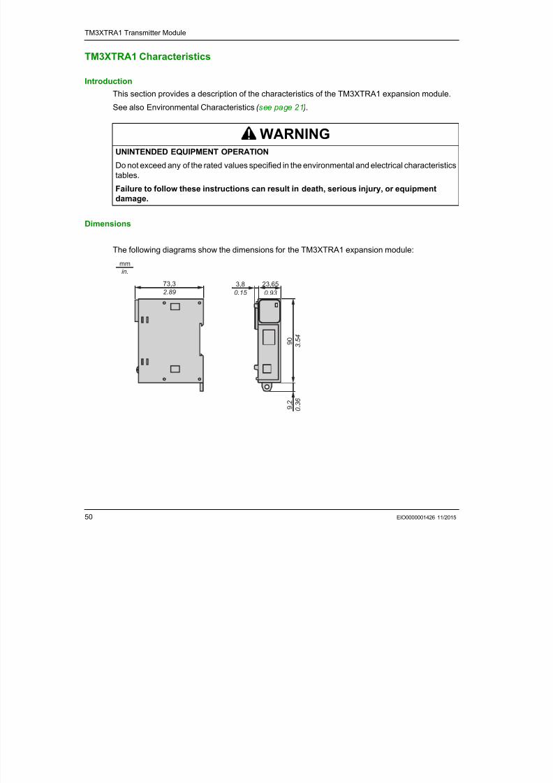
The following diagrams show the dimensions for the TM3XTRA1 expansion module:
WARNINGUNINTENDED EQUIPMENT OPERATION
Do not exceed any of the rated values specified in the environmental and electrical characteristicstables.
Failure to follow these instructions can result in death, serious injury, or equipment
damage.
73,3
2.89
23,65
0.93
3,8
0.15
9 0
3 . 5
4
9 , 2
0
. 3 6
mm
in.
TM3XTRA1 Transmitter Module
7/23/2019 Tm3 Transm Receiver Guide
http://slidepdf.com/reader/full/tm3-transm-receiver-guide 51/66
TM3XTRA1 Transmitter Module
EIO0000001426 11/2015 51
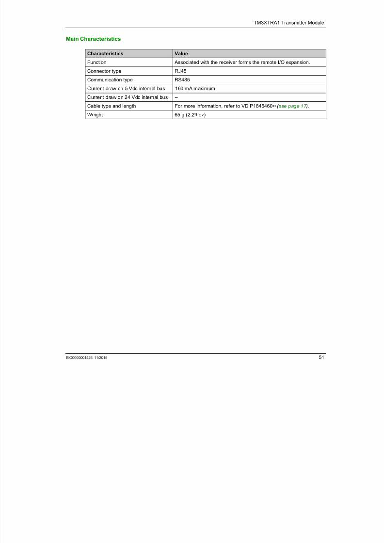
Main Characteristics
Characteristics Value
Function Associated with the receiver forms the remote I/O expansion.
Connector type RJ45
Communication type RS485
Current draw on 5 Vdc internal bus 160 mA maximum
Current draw on 24 Vdc internal bus –
Cable type and length For more information, refer to VDIP1845460•• ( see page 17 ).
Weight 65 g (2.29 oz)
TM3XTRA1 Transmitter Module
7/23/2019 Tm3 Transm Receiver Guide
http://slidepdf.com/reader/full/tm3-transm-receiver-guide 52/66
TM3XTRA1 Transmitter Module
52 EIO0000001426 11/2015
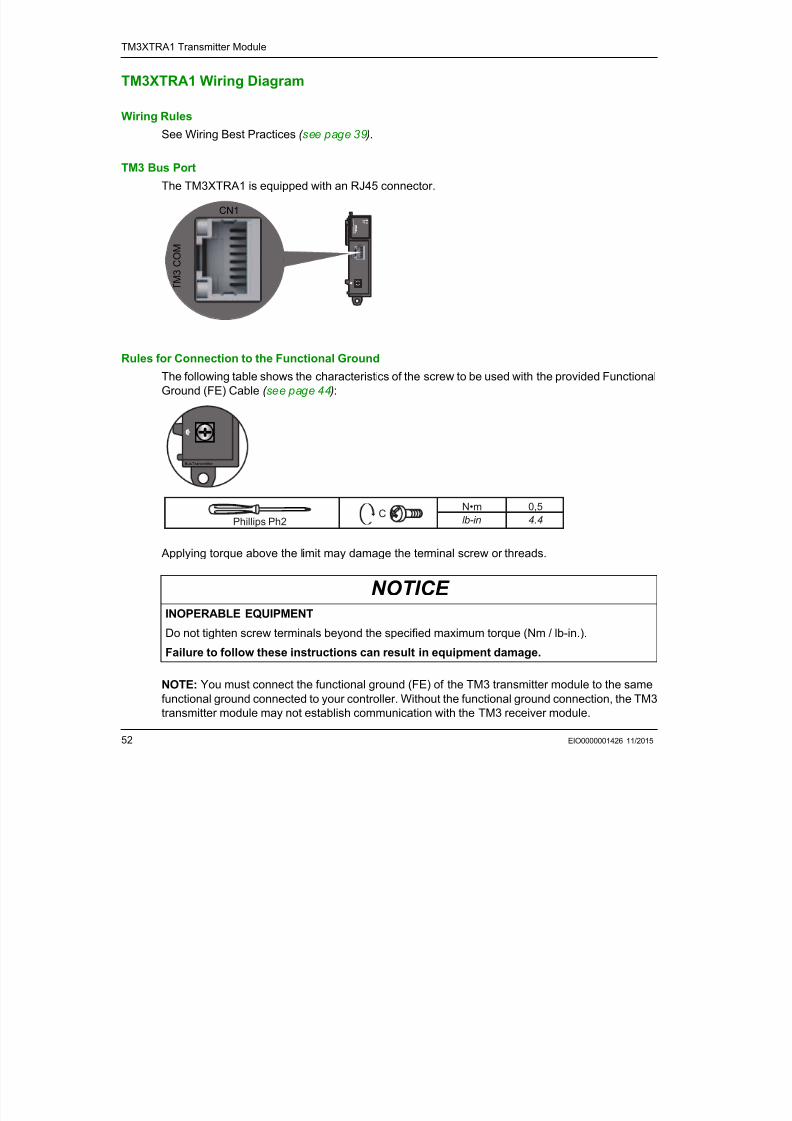
TM3XTRA1 Wiring Diagram
Wiring Rules
See Wiring Best Practices ( see page 39 ).
TM3 Bus Port
The TM3XTRA1 is equipped with an RJ45 connector.
Rules for Connection to the Functional Ground
The following table shows the characteristics of the screw to be used with the provided Functional
Ground (FE) Cable ( see page 44 ):
Applying torque above the limit may damage the terminal screw or threads.
NOTE: You must connect the functional ground (FE) of the TM3 transmitter module to the same
functional ground connected to your controller. Without the functional ground connection, the TM3transmitter module may not establish communication with the TM3 receiver module.
Bus Transmitter
T M 3 C O M
T M 3 X T R A 1
CN1
T M 3 C O M
CN1
NOTICE INOPERABLE EQUIPMENT
Do not tighten screw terminals beyond the specified maximum torque (Nm / lb-in.).
Failure to follow these instructions can result in equipment damage.
Bus Transmitter
0,5
4.4
N•m
lb-inPhillips Ph2C
TM3XTRA1 Transmitter Module

7/23/2019 Tm3 Transm Receiver Guide
http://slidepdf.com/reader/full/tm3-transm-receiver-guide 53/66
TM3XTRA1 Transmitter Module
EIO0000001426 11/2015 53
NOTICE
INOPERABLE EQUIPMENT Ensure that the functional ground cable is securely connected between the functional ground
screw of the TM3 transmitter module and the functional ground of the controller.
Monitor the status of the TM3 bus within your application to determine the correct behavior of
the TM3 bus in case of disconnection from the functional ground of the TM3 transmitter
module.
Failure to follow these instructions can result in equipment damage.
TM3XTRA1 Transmitter Module

7/23/2019 Tm3 Transm Receiver Guide
http://slidepdf.com/reader/full/tm3-transm-receiver-guide 54/66
54 EIO0000001426 11/2015
ModiconTM3
TM3XREC1 Receiver ModuleEIO0000001426 11/2015
7/23/2019 Tm3 Transm Receiver Guide
http://slidepdf.com/reader/full/tm3-transm-receiver-guide 55/66
EIO0000001426 11/2015 55
TM3XREC1 Receiver Module
Chapter 4
TM3XREC1 Receiver Module
Overview
This chapter describes the TM3XREC1 expansion module, its characteristics, and its connection
to the different sensors.
What Is in This Chapter?This chapter contains the following topics:
Topic Page
TM3XREC1 Presentation 56
TM3XREC1 Characteristics 58
TM3XREC1 Wiring Diagram 60
TM3XREC1 Receiver Module
7/23/2019 Tm3 Transm Receiver Guide
http://slidepdf.com/reader/full/tm3-transm-receiver-guide 56/66
56 EIO0000001426 11/2015
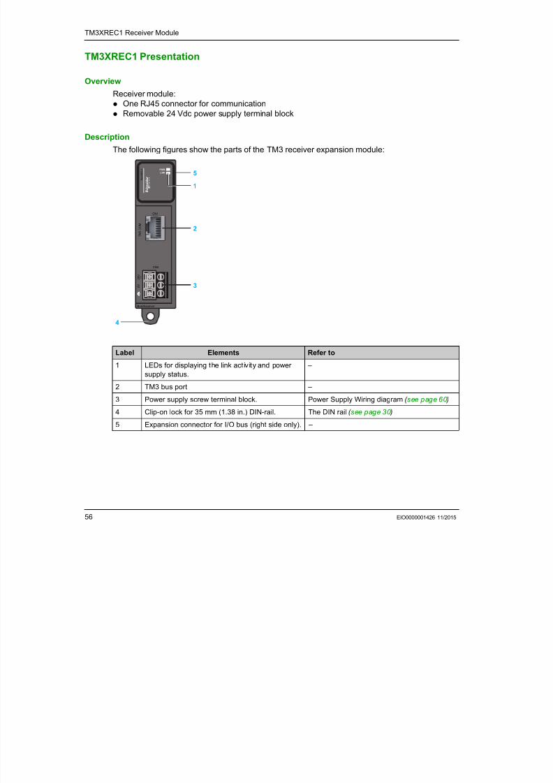
TM3XREC1 Presentation
Overview
Receiver module:
One RJ45 connector for communication
Removable 24 Vdc power supply terminal block
Description
The following figures show the parts of the TM3 receiver expansion module:
Label Elements Refer to
1 LEDs for displaying the link activity and power
supply status.
–
2 TM3 bus port –
3 Power supply screw terminal block. Power Supply Wiring diagram ( see page 60 )
4 Clip-on lock for 35 mm (1.38 in.) DIN-rail. The DIN rail ( see page 30 )
5 Expansion connector for I/O bus (right side only). –
Bus Receiver
CN2
T M 3 C O M
T M 3 X R E C 1
CN1
0 V
2 4 V c
5
4
1
2
3
TM3XREC1 Receiver Module

7/23/2019 Tm3 Transm Receiver Guide
http://slidepdf.com/reader/full/tm3-transm-receiver-guide 57/66
EIO0000001426 11/2015 57
Status LEDs
The following figure shows the status LEDs:
This table describes the status LEDs:
LED Color Status Description
Power (PWR) Green On Power supply for TM3 bus is available.
Off Power supply for TM3 bus is not available.
Link (LNK) Green On Link/data signal is detected from the transmitter.Off No link/data signal is detected from the transmitter.
TM3XREC1 Receiver Module
7/23/2019 Tm3 Transm Receiver Guide
http://slidepdf.com/reader/full/tm3-transm-receiver-guide 58/66
58 EIO0000001426 11/2015
TM3XREC1 Characteristics
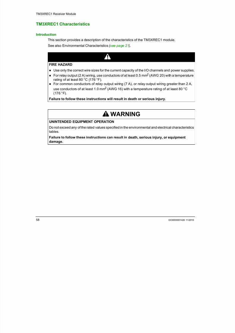
Introduction
This section provides a description of the characteristics of the TM3XREC1 module.
See also Environmental Characteristics ( see page 21 ).
DANGERFIRE HAZARD
Use only the correct wire sizes for the current capacity of the I/O channels and power supplies. For relay output (2 A) wiring, use conductors of at least 0.5 mm2 (AWG 20) with a temperature
rating of at least 80 °C (176 °F).
For common conductors of relay output wiring (7 A), or relay output wiring greater than 2 A,
use conductors of at least 1.0 mm2 (AWG 16) with a temperature rating of at least 80 °C
(176 °F).
Failure to follow these instructions will result in death or serious injury.
WARNINGUNINTENDED EQUIPMENT OPERATION
Do not exceed any of the rated values specified in the environmental and electrical characteristics
tables.
Failure to follow these instructions can result in death, serious injury, or equipment
damage.
TM3XREC1 Receiver Module
7/23/2019 Tm3 Transm Receiver Guide
http://slidepdf.com/reader/full/tm3-transm-receiver-guide 59/66
EIO0000001426 11/2015 59
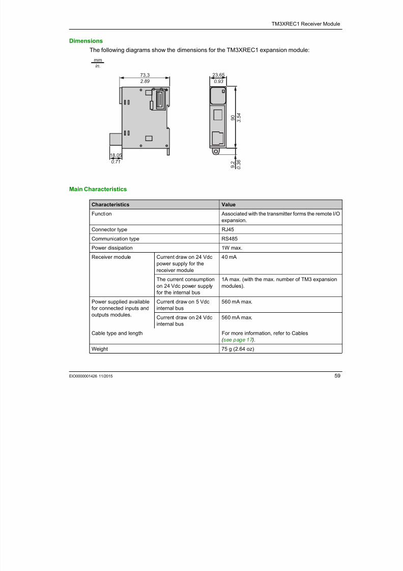
Dimensions
The following diagrams show the dimensions for the TM3XREC1 expansion module:
Main Characteristics
73,3
2.89
23,65
0.93
18,05
0.71
9 0
3
. 5 4
mm
in.
9 , 2
0 . 3
6
Characteristics Value
Function Associated with the transmitter forms the remote I/O
expansion.
Connector type RJ45
Communication type RS485Power dissipation 1W max.
Receiver module Current draw on 24 Vdc
power supply for the
receiver module
40 mA
The current consumption
on 24 Vdc power supply
for the internal bus
1A max. (with the max. number of TM3 expansion
modules).
Power supplied available
for connected inputs and
outputs modules.
Current draw on 5 Vdc
internal bus
560 mA max.
Current draw on 24 Vdc
internal bus
560 mA max.
Cable type and length For more information, refer to Cables
( see page 17 ).
Weight 75 g (2.64 oz)
TM3XREC1 Receiver Module
7/23/2019 Tm3 Transm Receiver Guide
http://slidepdf.com/reader/full/tm3-transm-receiver-guide 60/66
60 EIO0000001426 11/2015
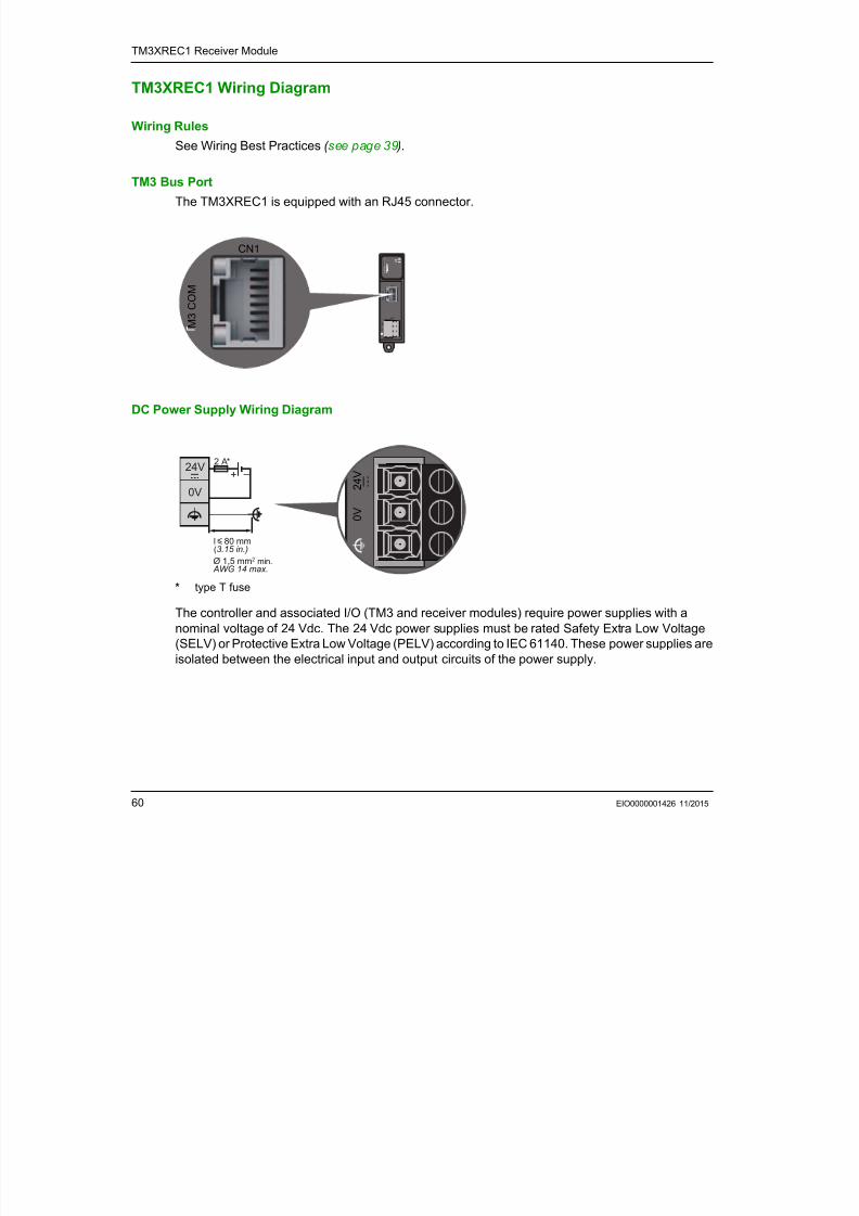
TM3XREC1 Wiring Diagram
Wiring Rules
See Wiring Best Practices ( see page 39 ).
TM3 Bus Port
The TM3XREC1 is equipped with an RJ45 connector.
DC Power Supply Wiring Diagram
* type T fuse
The controller and associated I/O (TM3 and receiver modules) require power supplies with a
nominal voltage of 24 Vdc. The 24 Vdc power supplies must be rated Safety Extra Low Voltage
(SELV) or Protective Extra Low Voltage (PELV) according to IEC 61140. These power supplies are
isolated between the electrical input and output circuits of the power supply.
Bus Receiver
CN2
T M 3 C O M
T M 3 X R E C
1
CN1
0 V
2 4 V c M
3 C O M
CN1
l y 80 mm(3.15 in.)
Ø 1,5 mm2 min. AWG 14 max.
–+24V
0V
2 A*
c
0 V
2 4 V c
TM3XREC1 Receiver Module
7/23/2019 Tm3 Transm Receiver Guide
http://slidepdf.com/reader/full/tm3-transm-receiver-guide 61/66
EIO0000001426 11/2015 61
1For compliance to UL (Underwriters Laboratories) requirements, the power supply must also be
of a type Class 2 with a maximum power output availability of less than 100 VA (approximately 4 Aat nominal voltage). A Class 2 circuit requires dry indoor use only in non-hazardous locations, and
must be grounded. You must separate Class 2 circuits from other circuits. If a non-Class 2 power
source is used, either power supply or transformer, you must impose a current limiting device such
as a fuse or a circuit breaker with a maximum rating of 4 A, but never exceeding the limits indicated
in the electric characteristics and wiring diagrams for this equipment. If the indicated rating of the
electrical characteristics or wiring diagrams are greater than 4 A, multiple Class 2 power supplies
may be used.
DC Power Supply Rules
If 2 separate power supplies are used for the receiver and the controller, the TM3 receiver module
power supply must be switched on before the controller power supply. If not, the TM3 bus does not
start, and all modules are in Reset state (all outputs are forced to 0).
When the TM3 receiver module and the controller are supplied by the same power supply, the
whole configuration starts together properly.
If only the TM3 receiver module is powered (controller not supplied), the TM3 modules after theTM3 receiver module are in Reset state (all outputs are forced to 0).
Further, you must connect the functional ground via the power supply, and the functional or
protective ground of the power supply to the same equipotential functional ground (FE) of the
controller and TM3 transmitter module.
NOTE: You must connect the functional ground (FE) of the TM3 receiver module to the same
functional ground connected to your controller and TM3 transmitter module. Without the functional
ground connection, the TM3 transmitter module may not establish communication with the TM3receiver module, or possibly damage your equipment.
WARNING
POTENTIAL OF OVERHEATING AND FIRE
Do not connect the equipment directly to line voltage.
Use only isolating PELV or SELV power supplies to supply power to the equipment1.
Failure to follow these instructions can result in death, serious injury, or equipment
damage.
TM3XREC1 Receiver Module

7/23/2019 Tm3 Transm Receiver Guide
http://slidepdf.com/reader/full/tm3-transm-receiver-guide 62/66
62 EIO0000001426 11/2015
NOTICE
INOPERABLE EQUIPMENT Ensure that the functional ground power supply connection of the TM3 receiver module is
securely connected to the functional ground of the controller system.
Monitor the status of the TM3 bus within your application to determine the correct behavior of
TM3 bus in case of disconnection from the functional ground.
Failure to follow these instructions can result in equipment damage.
ModiconTM3
Glossary
EIO0000001426 11/2015
7/23/2019 Tm3 Transm Receiver Guide
http://slidepdf.com/reader/full/tm3-transm-receiver-guide 63/66
EIO0000001426 11/2015 63
Glossary
E
EIA rack
(electronic industries alliance rack ) A standardized (EIA 310-D, IEC 60297, and DIN 41494
SC48D) system for mounting various electronic modules in a stack or rack that is 19 inches
(482.6 mm) wide.
EN
EN identifies one of many European standards maintained by CEN (European Committee for
Standardization), CENELEC (European Committee for Electrotechnical Standardization), or ETSI
(European Telecommunications Standards Institute).
expansion connector
A connector to attach expansion I/O modules.
HHE10
Rectangular connector for electrical signals with frequencies below 3 MHz, complying with IEC
60807-2.
I
IEC(international electrotechnical commission) A non-profit and non-governmental international
standards organization that prepares and publishes international standards for electrical,
electronic, and related technologies.
IP 20
(ingress protection) The protection classification according to IEC 60529 offered by an enclosure,
shown by the letter IP and 2 digits. The first digit indicates 2 factors: helping protect persons and
for equipment. The second digit indicates helping protect against water. IP 20 devices help protect
against electric contact of objects larger than 12.5 mm, but not against water.
N
NEMA
(national electrical manufacturers association) The standard for the performance of various
classes of electrical enclosures. The NEMA standards cover corrosion resistance, ability to help
protect from rain, submersion, and so on. For IEC member countries, the IEC 60529 standardclassifies the ingress protection rating for enclosures.
Glossary
7/23/2019 Tm3 Transm Receiver Guide
http://slidepdf.com/reader/full/tm3-transm-receiver-guide 64/66
64 EIO0000001426 11/2015
P
PE
(Protective Earth) A common grounding connection to help avoid the hazard of electric shock bykeeping any exposed conductive surface of a device at earth potential. To avoid possible voltage
drop, no current is allowed to flow in this conductor (also referred to as protective ground in North
America or as an equipment grounding conductor in the US national electrical code).
R
RJ45
A standard type of 8-pin connector for network cables defined for Ethernet.
T
terminal block
(terminal block ) The component that mounts in an electronic module and provides electrical
connections between the controller and the field devices.
ModiconTM3
Index
EIO000000142611/2015

7/23/2019 Tm3 Transm Receiver Guide
http://slidepdf.com/reader/full/tm3-transm-receiver-guide 65/66
EIO0000001426 11/2015 65
Index
Aassembling to a controller, 34
Ccertifications and standards, 24
controllers
disassembling a module, 36
Ddescription
transmitter and receiver, 15
dimensions
TM3XTRA1, 50
EElectromagnetic Susceptibility, 22
environmental characteristics, 21
Ggrounding, 43
Mminimum clearances, 29
mounting position, 29
Ppresentation
TM3XTRA1, 48
Sspecifications
transmitter and receiver modules, 15
TTM3XREC1, 56
TM3XREC1 receiver module, 55
TM3XTRA1, 50
presentation, 48
TM3XTRA1 transmitter module, 47
transmitter and receiver modules
description, 15
specifications, 15
Wwiring rules, 39
Index

7/23/2019 Tm3 Transm Receiver Guide
http://slidepdf.com/reader/full/tm3-transm-receiver-guide 66/66