tm general information 3-series & h-series gear pumps€¦ · tm liquiflo's rotogear...
TRANSCRIPT

TM
Liquiflo's Rotogear 3-series and H-series gear pumps handle flows from 0.1 to 58 GPM and up to 225 PSI* of pressure. They were specificallydesigned to meet the needs of the chemical processing industry and will handle a wide range of difficult pumping applications.
* For higher pressure applications, please contact factory.
ROTOGEAR®
GENERAL INFORMATION 3-SERIES & H-SERIES GEAR PUMPS
WHY USE GEAR PUMPS?
Gear Pumps are positive displacementpumps that are frequently used formetering and transferring viscous as well as thin fluids at higher differentialpressures.
Gear pumps are an economicalalternative to Diaphragm pumps formetering applications and do not pulseor require an air source to operate.They generally last longer in continuousduty applications than Diaphragm,Progressive Cavity or Peristaltic pumpsthat require frequent part replacements.However, the real value of a gear pumpderives from the flexibility and availabilityof materials of construction and thesealing arrangements which facilitateoptimizing the pump for the givenservice.
WHY USE MAG-DRIVE GEAR PUMPS?
Magnetically Coupled Pumps offera simple and cost effective solution tosealing toxic, noxious, crystallizing ormost other fluids that present problemsfor single seals and would thereforerequire use of a double mechanicalseal. Magnetically-coupled pumpseliminate the need for cooling loopsthat are required by double mechanicalseals. Two problems commonlyassociated with cooling loops areselecting a compatible barrier fluidand disposing of the barrier fluid inthe event of an inboard seal failure.
Liquiflo has extended the useful rangeof gear pumps into low-viscosity fluidsby using a wide variety of non-metallicself-lubricating components.
Advantages and attributes over othertypes of pumps are:◆ Low flow and high discharge
pressure◆ Virtually no pulsations◆ Self-priming◆ Lower NPSHR◆ Fewer wearing parts◆ Less auxiliary equipment required
(pulsation dampeners, compressors, dryers, etc.)
◆ Flow accuracies as low as 0.5%are achievable
◆ Easy to repair
Liquiflo has been producingmagnetically coupled pumps for more than twenty years with tens ofthousands of successful applications.Magnetically-coupled versions areavailable for all of Liquiflo's productlines including 2, 3, 4, & H-SeriesGear Pumps, and the Centry®
Series Centrifugal Pumps.
Advantages of Mag-Drive Pumps:◆ Less expensive than
double-sealed arrangements◆ Eliminates cooling loops required
on double seal arrangements◆ Eliminates the need to dispose
of barrier fluids
Bearings
WearPlates
Gears
MechanicalSeal
Housings
StuffingBox
All pump components shown are availablein a wide selection of materials to handledifficult chemical pumping applications.
Bearings Optional Silicon Carbide Bearings and hardened Shafts provide extended service life.
Wear Allow pump to be rebuilt Plates to like-new condition.
Gears Material selection includesmetal/non-metal self-lubricating combinations for thin fluids.
Housings Available in several materialsfor a wide range of corrosion resistance.
Stuffing Universal Stuffing Box willBox accept packing, single-
mechanical seal, double-mechanical seal and external mechanical seal arrangements.
Mechanical Type 9 Seal: available in a Seal wide selection of materials
for pumping virtually any chemicals.
ContainmentCan
InnerMagnet
Containment Available in 316 SS, Alloy-C orCan Tefzel-lined Alloy-C.
Eliminates leakage associated with mechanical seals.
Inner Liquiflo’s standard Inner Magnets Magnets are made from
Samarium Cobalt which can be used at elevated temperatures.
4

TM
High-Viscosity FluidsWater treatment polymers and food materials up to 80,000 cps are typicalof the high-viscosity service of theRotogear® Series of gear pumps. Onhigh-viscosity applications, it is preferableand more efficient to use larger pumpsrunning at slower speeds.
MATERIALS AVAILABLE
Liquiflo’s Rotogear® 3-Seriesand H-Series Gear Pumpscome in a wide range ofmaterials to meet all of yourchemical processingapplications.
REPAIR KITS
Repair Kits simplify inventory andspeed repair. All parts can also bepurchased separately.
Repair kits contain all componentsto completely rebuild your LiquifloGear Pump to like-new condition(all items except the housings are included).
Repair Kits Include:• Gears • Bearings • O-Rings• Shafts • Wear Plates • Retaining Rings• Keys • Pins • Seals (if applicable)
CARTRIDGE
A cartridge is a complete mag-drive pump less theouter magnet and pedestal.A cartridge replacement is aconvenient way to quickly replace a pump that requiresmaintenance.
HOUSINGS GEARS WEAR PLATES BEARINGS SHAFTS
316 SS 316 SS Carbon Carbon 316 SS
Alloy-C Alloy-C Ceramic Teflon Alloy-C
Titanium Glass-filled PTFE Teflon Ryton Titanium
Delrin Ryton Silicon Carbide Ceramic Coated
Ryton PEEK PEEK Tungsten Carbide
Carbon Coated
Low-Viscosity FluidsFrequently, gear pumps are the preferred solution in low-viscosity pumping applications because of their hydraulics (low flow, high pressureand pulseless flow), compactness,efficiency and low cost. Liquiflo’s wideselection of materials allow for pumpcustomization to reduce premature shaft,gear, and bearing wear on low-viscosityfluids. Liquiflo has successfully pumpedliquids with viscosities as low as 0.3 CPS.
MeteringLiquiflo gear pumps are used in variable flow systems where the motorRPM is controlled to regulate pumpoutput. Flow rate, pH levels or RPM cantrigger the control of feedback signals.(Refer to the Engineering section formore details on gear pumps inmetering applications). The Rotogear®
Series is available in a wide variety of flow ranges (11 sizes offered),simplifying selection for meteringapplications.
L I Q U I F L O C H E M I C A L P R O C E S S I N G P U M P S
Liquiflo Gear Pumps handle a wide range of applications including the pumping oflow-viscosity and high-viscosity fluids, as well as complex metering applications.
Positive displacementpumps should be installedwith a relief valve in thedischarge line. This willprotect the pump andpiping against any type ofline blockage includingthe inadvertent closing ofan isolation valve. Liquiflomanufactures two sizesof relief valves in both 316 SS and Alloy-C.
RELIEF VALVES
5t e l . 9 0 8 . 5 1 8 . 0 7 7 7 f a x . 9 0 8 . 5 1 8 . 1 8 4 7 w w w . l i q u i f l o . c o m

TM
6
LONG-COUPLED MAG-DRIVE (312, 314 & H12 only)
TYPICALMOUNTINGCONFIGURATIONS
CLOSE-COUPLED MAG-DRIVE
Close-Coupled Option eliminates manualalignment of pump and motor.
ANSI, DIN, JISFlanges are available
Sanitary Fittings areavailable for food &drug applications
OPTIONSLiquiflo has several options available for its complete line of Positive Displacement Gear Pumps, as well asoffering a complete line of standard pumps. Liquiflowill custom engineer its pumps and options to fityour specific requirements.
Temperature ControlJackets can maintain thepump at either elevatedor reduced temperatures.Commonly used whenpumping liquids thatsolidify or becomedifficult to pumpwhen the temperaturedecreases.
The S-Adapter isavailable for long-coupling mag-drivepumps; it isolates thepump from the motor.
SANITARYFITTINGS
RAISED-FACEFLANGES
CLAMP-ONTEMPERATURECONTROL JACKET
S-ADAPTER
GENERAL INFORMATION 3-SERIES & H-SERIES GEAR PUMPS
Features of Close-Coupled Design:• Eliminates difficulties and inconvenience of manually
aligning pump and motor
• Cast-iron bracket that rigidly supports pump & motor
• Dimensionally interchangeable with our Mag-Drive pumps
• Available for 56C, 143/145TC, IEC 71, 80, 90 frame motors
• Excellent for OEM applications
• Quickly and easily installed
CLOSE-COUPLED SEALED

TML I Q U I F L O C H E M I C A L P R O C E S S I N G P U M P S
SEALCONFIGURATIONS
FIG.1 LANTERN RING/PACKING SEAL
FIG.2 SINGLE MECHANICAL SEAL
FIG.4 DOUBLE MECHANICAL SEAL
FIG.3 EXTERNAL MECHANICAL SEAL
RANGE OF SEALS AVAILABLE
Liquiflo's Universal Front Housings will accommodate packing,as well as single and double mechanical seal configurations.
Fig. 1 Packing is suitable and the most economical for safe,non-hazardous liquids.
Fig. 2 Single Mechanical Seals are used when leakage needsto be minimized. Single seals have a viscosity limit of 5,000 cpsand a temperature limit of 500 ˚F.
Fig. 3 External Mechanical Seals are used to isolate the sealbody from the liquid being pumped or when pumping liquidunder vacuum conditions.
Fig. 4 Double Mechanical Seals require a flushing system and are typically used when pumping liquids that are abrasive,crystallize on contact with air, or are very dangerous.
SEAL MATERIALS AVAILABLE
PACKING SEAL SEAL SEAL WEDGES FACES SEATS
Braided Teflon Teflon Carbon CeramicGrafoil Grafoil Teflon Silicon Carbide
Silicon Carbide Tungsten Carbide
Gaskets
Seal Seat
HousingBolt
Plug
FrontHousing
Gland Bolts
GlandPlate
MechanicalSeal
FIG.5 EXPLODED VIEW OF SINGLE INTERNAL MECHANICAL SEAL
7t e l . 9 0 8 . 5 1 8 . 0 7 7 7 f a x . 9 0 8 . 5 1 8 . 1 8 4 7

t e l . 9 0 8 . 5 1 8 . 0 7 7 7 f a x . 9 0 8 . 5 1 8 . 1 8 4 7 w w w . l i q u i f l o . c o m
H-SERIES ROTOGEAR® EXTERNAL GEAR PUMPS
L I Q U I F L O C H E M I C A L P R O C E S S I N G P U M P S
TM
23

t e l . 9 0 8 . 5 1 8 . 0 7 7 7 f a x . 9 0 8 . 5 1 8 . 1 8 4 7 w w w . l i q u i f l o . c o m
H-SERIESROTOGEAR® EXTERNAL GEAR PUMPS
L I Q U I F L O C H E M I C A L P R O C E S S I N G P U M P S
SEALED
MAG-DRIVEClose-Coupled
SEALED H3F H5R H5F H7N H7R H7FMAG-DRIVE H3F-MC H5R-MC H5F-MC H7N-MC H7R-MC H7F-MC
Max Flow 1.4 GPM (5.3 LPM) 2.4 GPM (9.1 LPM) 3.4 GPM (13 LPM) 5.4 GPM (20.4 LPM) 8.6 GPM (32.5 LPM) 10.7 GPM (40.5 LPM)
Max Diff. Press. 225 PSI (15.5 BAR) 225 PSI (15.5 BAR) 225 PSI (15.5 BAR) 225 PSI (15.5 BAR) 225 PSI (15.5 BAR) 225 PSI (15.5 BAR)
Max Discharge 300 PSI (20.7 BAR) 300 PSI (20.7 BAR) 300 PSI (20.7 BAR) 225 PSI (15.5 BAR) 225 PSI (15.5 BAR) 225 PSI (15.5 BAR)
Max Temp. 500 ˚F (260 ˚C) 500 ˚F (260 ˚C) 500 ˚F (260 ˚C) 500 ˚F (260 ˚C) 500 ˚F (260 ˚C) 500 ˚F (260 ˚C)
Max Viscosity 100,000* CPS 100,000* CPS 100,000* CPS 100,000* CPS 100,000* CPS 100,000* CPS
Max Speed 1750 RPM 1750 RPM 1750 RPM 1750 RPM 1750 RPM 1750 RPM
NPSHR @ Max Speed 2 FT (0.6M) 2 FT (0.6M) 2 FT (0.6M) 5.2 FT (1.6M) 5.2 FT (1.6M) 5.2 FT (1.6M)
Weight (LBS)
Sealed 2.5 LBS (1.1 KGS) 3.5 LBS (1.6 KGS) 3.5 LBS (1.6 KGS) 6.5 LBS (2.9 KGS) 6.5 LBS (2.9 KGS) 6.5 LBS (2.9 KGS)
Mag-Drive 31 LBS (14 KGS) 32 LBS (15 KGS) 32 LBS (15 KGS) 36 LBS (16 KGS) 36 LBS (16 KGS) 36 LBS (16 KGS)
H-Series Up to 225 PSIdifferential pressure
Liquiflo’s H-Series high-pressuregear pumps are available in Sealedand Mag-Drive versions with flows up to approximately 30 GPM anddifferential pressures up to 225 PSI*.With similar outside dimensions to the 3-Series, the H-Series has larger shafts,bearings and seals for extended servicelife. These features allow it to handlehigher pressures and operate longer.
* 300 PSI possible on some models. Contact factory.
H-Series Specification Chart
* Higher viscosities possible. Contact factory.
TM
24

L I Q U I F L O C H E M I C A L P R O C E S S I N G P U M P S
COMPOSITE
GEAR PUMP
PERFORMANCE
CURVES
TEST FLUID: OIL
(100 CPS)
30
25
20
15
10
5
0
175
(12.1)
125
(8.6)
DIFFERENTIAL PRESSURE • PSI (BAR)
CA
PA
CIT
Y •
GP
M (L
PM
)
H7N • 1750 RPM
H3F • 1750 RPM
225
(15.5)
(114)
(95)
(76)
(57)
(38)
(19)
75
(5.2)
H5F • 1750 RPM
H7R • 1750 RPM
H7F • 1750 RPM
H12R • 1140 RPM
H12F • 1140 RPM
25
(1.7)H12R H12F
H12R-MC H12F-MC
22 GPM (83 LPM) 29 GPM (110 LPM)
225 PSI (15.5 BAR) 225 PSI (15.5 BAR)
270 PSI (18.6 BAR) 270 PSI (18.6 BAR)
500 ˚F (260 ˚C) 500 ˚F (260 ˚C)
100,000* CPS 100,000* CPS
1150 RPM 1150 RPM
5 FT (1.5M) 5 FT (1.5M)
52 LBS (23.6 KGS) 52 LBS (23.6 KGS)
70 LBS (32 KGS) 70 LBS (32 KGS)
TM
LONG-COUPLED ONLY
25

26
Bearings
Wear Plates
IdlerGear
Seal Type
Size/Model,Housings
& Port Type
DriveGear
DriveShaft
IdlerShaft
OptionalShaft
Coating
1 2 3
4
5
6
7
8
10
11
12
13
O-Rings
Bearing FlushOption(not shown)
Retaining Ringsfor Gears(not shown)
Anti-rotationPins for Bearings(not shown)
PUMP MODEL CODING
9
Sealed Pump
Mag-Drive Pump
TM
t e l . 9 0 8 . 5 1 8 . 0 7 7 7 f a x . 9 0 8 . 5 1 8 . 1 8 4 7 w w w . l i q u i f l o . c o m
L I Q U I F L O C H E M I C A L P R O C E S S I N G P U M P S
H - S E R I E SR O T O G E A R ®
E X T E R N A LG E A R P U M P
MagneticCoupling
14
8 Bore Size forOuter Magnet(not shown)
15
ContainmentCan
Other modelcode positions are the same asshown above forthe sealed pump.

27
TM
H3 H5 H7 H7N H12
F = Full Capacity ■ ■ ■ � ■R = Reduced Capacity � ■ ■ � ■
S = 316 SS NPT ■ ■ ■ ■ ■H = Alloy-C NPT ■ ■ ■ ■ ■L = 316 SS Flanged ■ ■ ■ ■ ■C = Alloy-C Flanged ■ ■ ■ ■ ■X = 316 SS BSPT ■ ■ ■ ■ ■Y = Alloy-C BSPT ■ ■ ■ ■ ■
1 = Alloy-C ■ ■ ■ ■ ■6 = 316 SS ■ ■ ■ ■ ■P = PEEK ■ ■ ■ ■ ■
1 = Alloy-C ■ ■ ■ ■ ■6 = 316 SS ■ ■ ■ ■ ■8 = Ryton ■ ■ ■ ■ ■P = PEEK ■ ■ ■ ■ ■
E = Carbon 60 ■ ■ ■ ■ ■3 = Teflon ■ ■ ■ ■ ■4 = Ceramic ■ ■ ■ ■ ■P = PEEK ■ ■ ■ ■ ■
E = Carbon 60 ■ ■ ■ ■ ■B = Silicon Carbide ■ ■ ■ ■ ■P = PEEK ■ ■ ■ ■ ■
0 = 0.625” (56C) ■ ■ ■ ■ �1 = 0.875” (143/145TC) ■ ■ ■ ■ ■2 = 14 mm (IEC 71 - B5) ■ ■ ■ ■ �3 = 19 mm (IEC 80 - B5) ■ ■ ■ ■ �4 = 24 mm (IEC 90 - B5) � ■ ■ ■ �5 = 1.125” (182/184TC) � � ■ ■ �
U = Single-Int Carbon - Ceramic ■ ■ ■ ■ ■L = Packing Teflon ■ ■ ■ ■ ■R = Packing Grafoil ■ ■ ■ ■ ■
0 = Standard Housings ■ ■ ■ ■ �1 = Ext. Brg Flush ■ ■ ■ ■ ■2 = Int. Brg Flush ■ ■ ■ ■ ■
0 = Material same as housing (uncoated) ■ ■ ■ ■ ■1 = Ceramic ■ ■ ■ ■ ■2 = Tungsten Carbide ■ ■ ■ ■ ■
0 = Teflon ■ ■ ■ ■ ■6 = 316 SS / PFA encap. ■ ■ ■ ■ ■B = Buna-N ■ ■ ■ ■ ■E = EPDM ■ ■ ■ ■ ■V = Viton ■ ■ ■ ■ ■K = Kalrez ■ ■ ■ ■ ■
0 = Material same as housing ■ ■ ■ ■ ■
0 = Teflon ■ ■ ■ ■ �1 = Alloy-C ■ ■ ■ ■ ■6 = 316 SS ■ ■ ■ ■ ■
S = 33 in-lbs ■ � � � �B = 120 in-lbs ■ ■ ■ ■ �C = 240 in-lbs � ■ ■ ■ �K = 250 in-lbs � � � � ■J = 500 in-lbs � � � � ■
8 = Temperature Trim ■ ■ ■ ■ ■9 = Viscosity Trim ■ ■ ■ ■ ■S = Single Wall Can ■ ■ ■ ■ ■D = Dual-Kan ■ ■ ■ ■ ■
2PositionModel
3PositionBasic Material &
Port Type
4PositionDrive Gear
5PositionIdler Gear
6PositionWear Plates
7PositionBearings
8PositionOuter Magnet Bore
(Mag Drive ONLY)
8PositionSeal Types
(Sealed pumps ONLY)
9PositionBearing Flush
10PositionShaft Coating
11PositionO-Rings
12PositionRetaining Rings
13PositionBearing Pins
14PositionMagnetic Coupling
(Mag Drive)
15Position(Options)
Pump Model1PositionModel
Sample Model No.
Position No.
H5 F S 6 P E E U 0 0 0 0 01 2 3 4 5 6 7 8 9 10 11 12 13 14 15
PUMP MODEL CODING
H5F S 6 P E E U 0 0 0 0 0
Pump Model H5F H5F PumpHousing Mat’l S 316 SS NPTDrive Gear Mat’l 6 316 SSIdler Gear Mat’l P PEEKWear Plate Mat’l E Carbon 60Bearing Mat’l E Carbon 60Seal Type U Single, Carbon-CeramicBearing Flush 0 NoneShaft Coating 0 NoneO-Rings 0 TeflonRetaining Ring 0 Same mat’l as housingsBearing Pins 0 TeflonMag Coupling N/AOptions N/A
1&2 3 4 5 6 7 8 9 10 11 12 13 14 15
1 & 23456789
101112131415
Pos. Description Selection
EXAMPLE:H5FS6PEEU00000, designates a ModelH5F Pump with Single Mechanical Seal.
Liquiflo’s Model Code describesboth the pump’s size and materialselected. This model code is required for the future identification of yourpump when reordering either a pump or replacement parts. Model code ispermanently stamped into pumphousing.
� Available
❍ No longer available in new pumps.Parts available only for repair and replacement.
� Not Available
Flanges available:
ANSI, DIN, JIS
Or slip joint flanges conforming to the dimensionsof the standard.
H3 H5 H7 H12
NPT/BSPT 1/4 1/2 3/4 11/4
ANSI 150# RF FLG 1/2 1/2 3/4 11/2
DIN PN16 10 15 20 40
JIS 10K 10 15 20 40
Liquiflo H-Series Gear PumpsSelection & Availability
t e l . 9 0 8 . 5 1 8 . 0 7 7 7 f a x . 9 0 8 . 5 1 8 . 1 8 4 7

TM
PORT SIZE 1/4” NPT/BSPT or 1/2” FLG
MAX FLOW 1.4 GPM; 5.3 LPM
MAX DIFFERENTIAL PRESSURE 225 PSI; 15.5 BAR
MAX DISCHARGE PRESSURE 300 PSI; 20.7 BAR
MAX TEMPERATURE 500˚F; 260˚C
MIN TEMPERATURE -40˚F; -40˚C
MAX VISCOSITY 100,000* CPS
NPSHR @ 1750 RPM 2 FT; 0.6 M
LIFT (DRY) 1.5 FT; 0.45 M
WEIGHT (without motor)SEALED 2.5 LBS; 1.1 KGSMAG-DRIVE 31 LBS; 14 KGS
DIFFERENTIAL PRESSURE (PSI)
1.6
1.4
1.2
1.0
0.8
0.6
0.4
0.2
0755025 1000
1750
1500
900
PO
WE
R (
BH
P)
FLO
W (
GP
M)
1750
600
600
1140
0.6
0.5
0.4
0.3
0.2
0.1
0125
0 1 2 3 4 5 6 7 8 9
BAR
LPM
6
5
4
3
2
1
0
H3F SEALEDH3F-MC MAG-DR IVE
DIFFERENTIAL PRESSURE (PSI)
100755025 2000
1750
1500
1140
900
PO
WE
R (
BH
P)
FLO
W (
GP
M)
600
1750
1.6
1.4
1.2
1.0
0.8
0.6
0.4
0.2
0
600
0.6
0.5
0.4
0.3
0.2
0.1
0175150125 225
0 2 4 6 8
BAR10 12 14 16
LPM
6
5
4
3
2
1
0
100 CPS Fluid (Oil)
P E R F O R M A N C E C U R V E S
1 CPS Fluid (Water)
Dimensional Data (inches)
Dimensional Data (inches)
Long-Coupled: H3F Sealed
Close-Coupled: H3F-MC & H3F Sealed
Sealed Close Coupled: Sealed or Mag-Drive
28
1.34
2.75
1.38
3.19
2.69
0.19
0.27 DIA. THRU
L
CP
N
0.63
0.375DIA.
SHAFT
2.68
.875
4.50 PORT
CL
9.31
7.25
5.94
3.50 3.06 2.50 2.506.50
2.68
1.34
0.41 DIA.THRU
4.00 SHAFT
CL
1.375PORT
CL
NOTES: (1) Add .312 inches for Bearing Flush Plug.(2) Minimum dimension.
SEAL CONFIGURATIONSPACKING
DIMENSION SINGLE MECHANICAL SEALDOUBLE MECHANICAL SEAL
CP(1) 6.94N 0.81 (2)
L 5.44
H - S E R I E SR O T O G E A R ®
G E A R P U M P
t e l . 9 0 8 . 5 1 8 . 0 7 7 7 f a x . 9 0 8 . 5 1 8 . 1 8 4 7
* Higher viscosities possible. Contact factory.
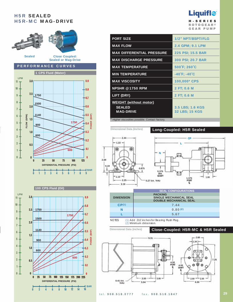
PORT SIZE 1/2” NPT/BSPT/FLG
MAX FLOW 2.4 GPM; 9.1 LPM
MAX DIFFERENTIAL PRESSURE 225 PSI; 15.5 BAR
MAX DISCHARGE PRESSURE 300 PSI; 20.7 BAR
MAX TEMPERATURE 500˚F; 260˚C
MIN TEMPERATURE -40˚F; -40˚C
MAX VISCOSITY 100,000* CPS
NPSHR @ 1750 RPM 2 FT; 0.6 M
LIFT (DRY) 2 FT; 0.6 M
WEIGHT (without motor)SEALED 3.5 LBS; 1.6 KGSMAG-DRIVE 32 LBS; 15 KGS
DIFFERENTIAL PRESSURE (PSI)
3.0
2.5
2.0
1.5
1.0
0.5
0
755025 1000
1750
1500
900
PO
WE
R (
BH
P)
FLO
W (
GP
M)
1750
600
600
1140
125
0.9
0.8
0.7
0.6
0.5
0.4
0.3
0.2
0.1
0
0 1 2 3 4 5 6 7 8 9
BAR
LPM
11
10
9
8
7
6
5
4
3
2
1
0
DIFFERENTIAL PRESSURE (PSI)
1750
1500
1140
900
PO
WE
R (
BH
P)
1750
600
100755025 2000 175150125 225
0.9
0.8
0.7
0.6
0.5
0.4
0.3
0.2
0.1
0
3.0
2.5
2.0
1.5
1.0
0.5
0
600
LPM
11
10
9
8
7
6
5
4
3
2
1
0
0 2 4 6 8
BAR10 12 14 16
100 CPS Fluid (Oil)
1 CPS Fluid (Water)
P E R F O R M A N C E C U R V E S
H5R SEALEDH5R-MC MAG-DR IVE
Long-Coupled: H5R Sealed
Close-Coupled: H5R-MC & H5R Sealed
Dimensional Data (inches)
Dimensional Data (inches)
Sealed Close Coupled: Sealed or Mag-Drive
4.50 PORT
CL
9.31
7.25
5.94
3.50 3.06 2.50 2.506.50
2.68
1.34
0.41 DIA.THRU
4.00 SHAFT
CL
29
TM
NOTES: (1) Add .312 inches for Bearing Flush Plug.(2) Minimum dimension.
SEAL CONFIGURATIONSPACKING
DIMENSION SINGLE MECHANICAL SEALDOUBLE MECHANICAL SEAL
CP(1) 7.44N 0.80 (2)
L 5.67
H - S E R I E SR O T O G E A R ®
G E A R P U M P
t e l . 9 0 8 . 5 1 8 . 0 7 7 7 f a x . 9 0 8 . 5 1 8 . 1 8 4 7
* Higher viscosities possible. Contact factory.
1.22
2.251.13
3.19
2.69
0.19
0.27 DIA. THRU
L
CP
N
1.00
0.375DIA.
SHAFT
0.875
2.44
1.375PORT
CL

TM
PORT SIZE 1/2” NPT/BSPT/FLG
MAX FLOW 3.4 GPM; 13 LPM
MAX DIFFERENTIAL PRESSURE 225 PSI; 15.5 BAR
MAX DISCHARGE PRESSURE 300 PSI; 20.7 BAR
MAX TEMPERATURE 500˚F; 260˚C
MIN TEMPERATURE -40˚F; -40˚C
MAX VISCOSITY 100,000* CPS
NPSHR @ 1750 RPM 2 FT; 0.6 M
LIFT (DRY) 4 FT; 1.2 M
WEIGHT (without motor)
SEALED 3.5 LBS; 1.6 KGSMAG-DRIVE 32 LBS; 15 KGS
DIFFERENTIAL PRESSURE (PSI)
4.0
3.5
3.0
2.5
2.0
1.5
1.0
0.5
0755025 1000
1750
1500
900
PO
WE
R (
BH
P)
FLO
W (
GP
M)
1750
600
600
1140
125
1.2
1.0
0.8
0.6
0.4
0.2
0
0 1 2 3 4 5 6 7 8 9
BAR
LPM
15
12
9
6
3
0
H5F SEALEDH5F-MC MAG-DR IVE
4.0
3.5
3.0
2.5
2.0
1.5
1.0
0.5
0
DIFFERENTIAL PRESSURE (PSI)
1750
1500
1140
900
PO
WE
R (
BH
P)
FLO
W (
GP
M)
600
100755025 2000 175150125 225
600
1.2
1.0
0.8
0.6
0.4
0.2
0
0 2 4 6 8
BAR10 12 14 16
1750
LPM
15
12
9
6
3
0
Long-Coupled: H5F Sealed
Close-Coupled: H5F-MC & H5F Sealed
100 CPS Fluid (Oil)
P E R F O R M A N C E C U R V E S
1 CPS Fluid (Water)
Dimensional Data (inches)
Dimensional Data (inches)
Sealed Close Coupled: Sealed or Mag-Drive
30
4.50 PORT
CL
9.31
7.25
5.94
3.50 3.06 2.50 2.506.50
2.68
1.34
0.41 DIA.THRU
4.00 SHAFT
CL
NOTES: (1) Add .312 inches for Bearing Flush Plug.(2) Minimum dimension.
SEAL CONFIGURATIONSPACKING
DIMENSION SINGLE MECHANICAL SEALDOUBLE MECHANICAL SEAL
CP(1) 7.44N 0.80 (2)
L 5.67
H - S E R I E SR O T O G E A R ®
G E A R P U M P
t e l . 9 0 8 . 5 1 8 . 0 7 7 7 f a x . 9 0 8 . 5 1 8 . 1 8 4 7
* Higher viscosities possible. Contact factory.
1.22
2.251.13
3.19
2.69
0.19
0.27 DIA. THRU
L
CP
N
1.00
0.375DIA.
SHAFT
0.875
2.44
1.375PORT
CL

Dimensional Data (inches)
Dimensional Data (inches)
DIFFERENTIAL PRESSURE (PSI)
6
5
4
3
2
1
0755025 1000
1750
1500
900
PO
WE
R (
BH
P)
FLO
W (
GP
M)
1750
600
600
1140
2.0
1.8
1.6
1.4
1.2
1.0
0.8
0.6
0.4
0.2
0125
0 1 2 3 4 5 6 7 8 9
BAR
LPM22
20
18
16
14
12
10
8
6
4
2
0
6
5
4
3
2
1
0
DIFFERENTIAL PRESSURE (PSI)
1750
1500
1140
900
PO
WE
R (
BH
P)
FLO
W (
GP
M)
1750
600
100755025 2000 175150125 225
600
2.0
1.8
1.6
1.4
1.2
1.0
0.8
0.6
0.4
0.2
0
LPM22
20
18
16
14
12
10
8
6
4
2
0
0 2 4 6 8
BAR10 12 14 16
100 CPS Fluid (Oil)
1 CPS Fluid (Water)
P E R F O R M A N C E C U R V E S
H7N SEALEDH7N-MC MAG-DR IVE
PORT SIZE 3/4” NPT/BSPT/FLG
MAX FLOW 5.4 GPM; 20.4 LPM
MAX DIFFERENTIAL PRESSURE 225 PSI; 15.5 BAR
MAX DISCHARGE PRESSURE 225 PSI; 15.5 BAR
MAX TEMPERATURE 500˚F; 260˚C
MIN TEMPERATURE -40˚F; -40˚C
MAX VISCOSITY 100,000* CPS
NPSHR @ 1750 RPM 5.2 FT; 1.6 M
LIFT (DRY) 6 FT; 1.8 M
WEIGHT (without motor)SEALED 6.5 LBS; 3 KGSMAG-DRIVE 36 LBS; 16 KGS
Long-Coupled: H7N Sealed
Close-Coupled: H7N-MC & H7N Sealed
1.66
3.32
3.94
0.19
0.28 DIA. THRU
L
CP
N
0.875
0.625SHAFTDIA.
1.25
1.31
2.62 2.000PORT
CL
10.72
7.25
5.94
3.50 3.75 2.50
6.50
3.321.66
0.41 DIA.THRU
2.50
4.50 PORT
CL4.00 SHAFT
CL
3.19
NOTES: (1) Add .312 inches for Bearing Flush Plug.(2) Minimum dimension.
SEAL CONFIGURATIONSPACKING
DIMENSION SINGLE MECHANICAL SEALDOUBLE MECHANICAL SEAL
CP(1) 8.20N 0.94 (2)
L 5.98
31
TM
H - S E R I E SR O T O G E A R ®
G E A R P U M P
t e l . 9 0 8 . 5 1 8 . 0 7 7 7 f a x . 9 0 8 . 5 1 8 . 1 8 4 7
* Higher viscosities possible. Contact factory.
Sealed Close Coupled: Sealed or Mag-Drive

TM
DIFFERENTIAL PRESSURE (PSI)
755025 1000
1750
1500
900
PO
WE
R (
BH
P)
FLO
W (
GP
M)
1750
600
600
1140
3.0
2.5
2.0
1.5
1.0
0.5
0125
0 1 2 3 4 5 6 7 8 9
BAR
LPM
36
32
28
24
20
16
12
8
4
0
10
9
8
7
6
5
4
3
2
1
0
H7R SEALEDH7R-MC MAG-DR IVE
10
9
8
7
6
5
4
3
2
1
0
DIFFERENTIAL PRESSURE (PSI)
1750
1500
1140
900
PO
WE
R (
BH
P)
FLO
W (
GP
M)
1750
600
100755025 2000 175150125 225
600
3.0
2.5
2.0
1.5
1.0
0.5
0
LPM
36
32
28
24
20
16
12
8
4
0
0 2 4 6 8
BAR10 12 14 16
Long-Coupled: H7R Sealed
Close-Coupled: H7R-MC & H7R Sealed
100 CPS Fluid (Oil)
P E R F O R M A N C E C U R V E S
1 CPS Fluid (Water)
PORT SIZE 3/4” NPT/BSPT/FLG
MAX FLOW 8.6 GPM; 32.5 LPM
MAX DIFFERENTIAL PRESSURE 225 PSI; 15.5 BAR
MAX DISCHARGE PRESSURE 225 PSI; 15.5 BAR
MAX TEMPERATURE 500˚F; 260˚C
MIN TEMPERATURE -40˚F; -40˚C
MAX VISCOSITY 100,000* CPS
NPSHR @ 1750 RPM 5.2 FT; 1.6 M
LIFT (DRY) 6 FT; 1.8 M
WEIGHT (without motor)SEALED 6.5 LBS; 3 KGSMAG-DRIVE 36 LBS; 16 KGS
Dimensional Data (inches)
Dimensional Data (inches)
32
1.66
3.32
3.94
0.19
0.28 DIA. THRU
L
CP
N
0.875
0.625SHAFTDIA.
1.25
1.31
2.62 2.000PORT
CL
10.72
7.25
5.94
3.50 3.75 2.50
6.50
3.321.66
0.41 DIA.THRU
2.50
4.50 PORT
CL4.00 SHAFT
CL
3.19
NOTES: (1) Add .312 inches for Bearing Flush Plug.(2) Minimum dimension.
SEAL CONFIGURATIONSPACKING
DIMENSION SINGLE MECHANICAL SEALDOUBLE MECHANICAL SEAL
CP(1) 8.20N 0.94 (2)
L 5.98
H - S E R I E SR O T O G E A R ®
G E A R P U M P
t e l . 9 0 8 . 5 1 8 . 0 7 7 7 f a x . 9 0 8 . 5 1 8 . 1 8 4 7
* Higher viscosities possible. Contact factory.
Sealed Close Coupled: Sealed or Mag-Drive

Dimensional Data (inches)
DIFFERENTIAL PRESSURE (PSI)
12
10
8
6
4
2
0755025 1000
1750
1500
900
PO
WE
R (
BH
P)
FLO
W (
GP
M)
1750
600
600
1140
3.5
3.0
2.5
2.0
1.5
1.0
0.5
0125
0 1 2 3 4 5 6 7 8 9
BAR
LPM45
40
35
30
25
20
15
10
5
0
12
10
8
6
4
2
0
DIFFERENTIAL PRESSURE (PSI)
1750
1500
1140
900
PO
WE
R (
BH
P)
FLO
W (
GP
M)
1750
600
100755025 2000 175150125 225
600
3.5
3.0
2.5
2.0
1.5
1.0
0.5
0
0 2 4 6 8
BAR10 12 14 16
LPM45
40
35
30
25
20
15
10
5
0
100 CPS Fluid (Oil)
1 CPS Fluid (Water)
P E R F O R M A N C E C U R V E S
H7F SEALEDH7F-MC MAG-DR IVE
PORT SIZE 3/4” NPT/BSPT/FLG
MAX FLOW 10.7 GPM; 40.5 LPM
MAX DIFFERENTIAL PRESSURE 225 PSI; 15.5 BAR
MAX DISCHARGE PRESSURE 225 PSI; 15.5 BAR
MAX TEMPERATURE 500˚F; 260˚C
MIN TEMPERATURE -40˚F; -40˚C
MAX VISCOSITY 100,000* CPS
NPSHR @ 1750 RPM 5.2 FT; 1.6 M
LIFT (DRY) 7 FT; 2.1 M
WEIGHT (without motor)SEALED 6.5 LBS; 3 KGSMAG-DRIVE 36 LBS; 16 KGS
Close-Coupled: H7F-MC & H7F SealedDimensional Data (inches)
Long-Coupled: H7F Sealed
Sealed Close Coupled: Sealed or Mag-Drive
1.66
3.32
3.94
0.19
0.28 DIA. THRU
L
CP
N
0.875
0.625SHAFTDIA.
1.25
1.31
2.62 2.000PORT
CL
10.72
7.25
5.94
3.50 3.75 2.50
6.50
3.321.66
0.41 DIA.THRU
2.50
4.50 PORT
CL4.00 SHAFT
CL
3.19
NOTES: (1) Add .312 inches for Bearing Flush Plug.(2) Minimum dimension.
SEAL CONFIGURATIONSPACKING
DIMENSION SINGLE MECHANICAL SEALDOUBLE MECHANICAL SEAL
CP(1) 8.32N 0.94 (2)
L 5.98
33
TM
H - S E R I E SR O T O G E A R ®
G E A R P U M P
t e l . 9 0 8 . 5 1 8 . 0 7 7 7 f a x . 9 0 8 . 5 1 8 . 1 8 4 7
* Higher viscosities possible. Contact factory.
TM
Mag-DriveSealed
DIFFERENTIAL PRESSURE (PSI)
25
20
15
10
5
0755025 1000
1140
600
PO
WE
R (
BH
P)
FLO
W (
GP
M)
1140
300
300
900
125
0 1 2 3 4 5 6 7 8 9
BAR
LPM
90
80
70
60
50
40
30
20
10
0
8
7
6
5
4
3
2
1
0
H12R SEALEDH12R-MC MAG-DR IVE
25
20
15
10
5
0
DIFFERENTIAL PRESSURE (PSI)
1140
900
600
PO
WE
R (
BH
P)
FLO
W (
GP
M)
1140
300
100755025 2000 175150125 225
300
8
7
6
5
4
3
2
1
0
LPM
90
80
70
60
50
40
30
20
10
0
0 2 4 6 8
BAR10 12 14 16
100 CPS Fluid (Oil)
P E R F O R M A N C E C U R V E S
1 CPS Fluid (Water)
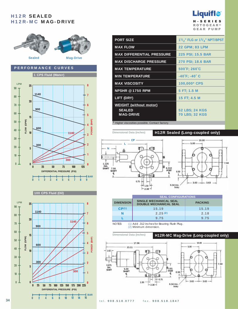
PORT SIZE 11/2” FLG or 11/4” NPT/BPST
MAX FLOW 22 GPM; 83 LPM
MAX DIFFERENTIAL PRESSURE 225 PSI; 15.5 BAR
MAX DISCHARGE PRESSURE 270 PSI; 18.6 BAR
MAX TEMPERATURE 500˚F; 260˚C
MIN TEMPERATURE -40˚F; -40˚ C
MAX VISCOSITY 100,000* CPS
NPSHR @ 1750 RPM 5 FT; 1.5 M
LIFT (DRY) 15 FT; 4.5 M
WEIGHT (without motor)SEALED 52 LBS; 24 KGSMAG-DRIVE 70 LBS; 32 KGS
0.50
17.06
7.50
13.11
3.63
5.00
10.00
0.34 DIA. THRU
3.63
1.62
0.875DIA.
SHAFT
2.38
0.751.50
5.00SHAFT
CL
3.81PORT
CL
NOTES: (1) Add .312 inches for Bearing Flush Plug.(2) Minimum dimension.
34
SEAL CONFIGURATIONS
DIMENSION SINGLE MECHANICAL SEAL PACKINGDOUBLE MECHANICAL SEAL
CP(1) 15.19 15.19N 2.25 (2) 2.18L 9.75 9.75
H12R-MC Mag-Drive (Long-coupled only)Dimensional Data (inches)
CPL
1.125DIA.
SHAFT
7.50
0.34 DIA. THRU
5.00
0.50
1.503.63
7.50SHAFT
CL
2.38
0.75 3.63
10.00
N
6.310PORT
CL
Dimensional Data (inches) H12R Sealed (Long-coupled only)
H - S E R I E SR O T O G E A R ®
G E A R P U M P
t e l . 9 0 8 . 5 1 8 . 0 7 7 7 f a x . 9 0 8 . 5 1 8 . 1 8 4 7
* Higher viscosities possible. Contact factory.

PORT SIZE 11/2” FLG or 11/4” NPT/BPST
MAX FLOW 29 GPM; 110 LPM
MAX DIFFERENTIAL PRESSURE 225 PSI; 15.5 BAR
MAX DISCHARGE PRESSURE 270 PSI; 18.6 BAR
MAX TEMPERATURE 500˚F; 260˚C
MIN TEMPERATURE - 40˚F; -40˚ C
MAX VISCOSITY 100,000* CPS
NPSHR @ 1750 RPM 5 FT; 1.5 M
LIFT (DRY) 17 FT; 5.2 M
WEIGHT (without motor)SEALED 52 LBS; 24 KGSMAG-DRIVE 70 LBS; 32 KGS
Mag-DriveSealed
DIFFERENTIAL PRESSURE (PSI)
35
30
25
20
15
10
5
0755025 1000
1140
600
PO
WE
R (
BH
P)
FLO
W (
GP
M)
1140
300
300
900
0 1 2 3 4 5 6 7 8 9
BAR
125
10
9
8
7
6
5
4
3
2
1
0
LPM
120
100
80
60
40
20
0
DIFFERENTIAL PRESSURE (PSI)
1140
900
600
PO
WE
R (
BH
P)
FLO
W (
GP
M)
1140
300
100755025 2000 175150125 225
300
10
9
8
7
6
5
4
3
2
1
0
35
30
25
20
15
10
5
0
LPM
120
100
80
60
40
20
0
0 2 4 6 8
BAR10 12 14 16
100 CPS Fluid (Oil)
1 CPS Fluid (Water)
P E R F O R M A N C E C U R V E S
H12F SEALEDH12F -MC MAG-DR IVE
H12F-MC Mag-Drive (Long-coupled only)Dimensional Data (inches)
0.50
17.06
7.50
13.11
3.63
5.00
10.00
0.34 DIA. THRU
3.63
1.62
0.875DIA.
SHAFT
2.38
0.751.50
CPL
1.125DIA.
SHAFT
7.50
0.34 DIA. THRU
5.00
0.50
1.503.63
7.50SHAFT
CL
2.38
0.75 3.63
10.00
N
6.310PORT
CL
5.00SHAFT
CL
3.81PORT
CL
35
TM
Dimensional Data (inches) H12F Sealed (Long-coupled only)
NOTES: (1) Add .312 inches for Bearing Flush Plug.(2) Minimum dimension.
SEAL CONFIGURATIONS
DIMENSION SINGLE MECHANICAL SEAL PACKINGDOUBLE MECHANICAL SEAL
CP(1) 15.19 15.19N 2.25 (2) 2.18L 9.75 9.75
H - S E R I E SR O T O G E A R ®
G E A R P U M P
t e l . 9 0 8 . 5 1 8 . 0 7 7 7 f a x . 9 0 8 . 5 1 8 . 1 8 4 7
* Higher viscosities possible. Contact factory.