tm 9-867 maintenance and care of hand tools - ibiblio
TRANSCRIPT

WAR DEPARTMENT TECHNICAL MANUAL
MAINTENANCEAND CARE OFHAND TOOLS
WAR DEPR TMEIENT . APRIL 1945

WAR DEPARTMENT TECHNICAL MANUAL
TM 9-867
MAINTENANCEAND CARE OFHAND TOOLS
WIAR DEPAR TMENT APRIL 1945
WAR DEPARTMENTWashington 25, D. C., 19 April 1945
TM 9-867, Maintenance and Care of Hand Tools, is published forthe information and guidance of all concerned.
A.G. 300.7 (20 Nov43)0.0. 461/60440 Raritan
BY ORDER OF THE SECRETARY OF WAR:
G. C. MARSHALL,Chief of Stafi.
OFFICIAL:J. A. ULIO,
Major General,The Adjutant General.
DISTRIBUTION: AAF (10); AGF (5); ASF (2); Dept (10); AAFComd (2); Arm & Sv Bd (1); S Div ASF (1);Tech Sv (2); SvC (10); PC&S (1); PE (Ord O)(5); Dist O 9 (5); Dist Br O 9 (3); Reg O 9(3); Establishments 9 (5); Decentralized SubO 9 (3); Gen & Sp Sv Sch (10); USMA (20);A (10); CHQ (10); D (2); B 2, 4-8, 18, 44 (1);R 2, 4-11, 17-19, 44, 55 (1); Bn 2-11, 17-19, 44,55 (1); C 2-11, 17-19, 44, 55 (1); AF (2);W (1); G (1); S (1); F (1).
Refer to FM 21-6 for explanation of distribution formula.

TM 9-867
CONTENTSSection Page
I Introduction ................................... 2
II Abrasive Wheels and Oilstones ................... 5
III Awls .......................................... 11
IV Bits and Boring Tools ........................... 14
V Braces and Hand Drills .......................... 24
VI Brushes ........................................ 26
VII Calipers ....................................... 29
VIII Chisels ........................................ 33
IX Clamps ........................................ 39
X Dividers ....................................... 42
XI Files and Rasps ................................ 44
XII Hammers, Mallets, Mauls, and Sledges............ 47
XIII Hand Grinders ................................. 51
XIV Hatchets, Axes, Mattocks, Adzes, and Shovels...... 53
XV Hydrometers ................................... 58
XVI Knives ....................................... 59
XVII Levels ........................................ 62
XVIII Nippers and Pliers .............................. 64
XIX Planes ........................................ 67
XX Punches ....................................... 74
XXI Reamers ....................................... 77
XXII Saws .......................................... 79
XXIII Scrapers ....................................... 89
XXIV Screwdrivers ................................... 92
XXV Shears ........................................ 96
XXVI Soldering Irons ................................ 100
XXVII Taps and Dies ............................... 103
XXVIII Vises .......................................... 107XXIX Wrenches ..................................... 109XXX References ..................................... 112
1

TM 9-867
Section I
INTRODUCTION
PURPOSE AND SCOPEThis manual is published for the information of arms and servicescharged with care of hand tools. It is intended to serve as a guideand ready source of definite information for personnel having someprevious knowledge in the operations covered. Insofar as prac-ticable, descriptive and use-of-tools information is omitted in orderto devote more space to care of tools. The efficiency of a mechanicand the tools he uses are determined to a great extent by the con-dition in which that mechanic keeps the tools. Likewise a mechaniccan be judged by the manner in which he handles and cares fortools. Micrometers, or any other precision tool, must be handledwith a careful, delicate touch and precision, commensurate with theextreme accuracy with which these tools are capable of measuring.It is with joy and great interest that everyone watches a skilledmechanic at his work, and this is largely due to the care and pre-cision with which he uses the tools of his trade. There is a place forevery tool and he keeps each tool in its place. He carefully wipeshis tools clean and dry before he places them in the tool box. If hedoes not expect to use a tool again for some time he lubricates it toprevent rusting.
NOTE: When storing tools under conditions of extreme humidity,moisture or salt air, it may be desirable to use preservative lubri-cating oil (medium) instead of the preservative lubricating oil(special) or engine oil (SAE 10) prescribed in this manual fornormal conditions.
LIST OF TOOLSAbrasive Wheels and Oilstones Braces and Hand Drills
Abrasive wheels BracesOilstones
Breast drillsAwls Hand drills
Handled seat awlBrad awlSaddler's sewing awl Brushes
Bits and Boring Tools Painter's dustAuger bits Sash toolCountersink bits Steel wireExpansive bitsScrewdriver bits StencilTwist drills - Varnish
2

CalipersFirm jointInside and outside microm-
etersInside and outside spring
Chisels
Blacksmith'sMachinist'sWoodworker's
ClampsC-typeHand screwHydraulic brake cylinderToolmaker's
DividersSpringWing
Files and Rasps
RoundHalf round raspFlatTaper
Hammers, Mallets, Mauls,and Sledges
HammersBell faced clawBlacksmith's cross peenBlacksmith's straight peenDing weightMachinist's ball peenPlain faced clawRivetingSoft face (copper, lead,leather, plastic, rawhide,rubber)Trimmer's
MalletsMaulsSledges
Blacksmith's cross peenBlacksmith's straight peen
Hand Grinders
Hatchets, Axes, Mattocks,Adzes, and Shovels
Hydrometers
KnivesDrawPocketPutty
Levels
Nippers and PliersNippers
Diagonal side cuttingHeavy typeLight type
Pliers
Adjustable combinationBrake springFlat-nosedHalf round-nosedRound-nosedSide cuttingTire chain repair
PlanesBench
ForeJackSmooth
Block
PunchesHollowSolid
CenterPinPrickTaper
3
TM 9-867

TM 9-867
ReamersHand reamers
StraightTaperExpansionAdjustable
Power reamersStraightTaper
Saws
BackBeadCompassCopingCrosscutDovetailHackKeyholeMiter boxNestedPatternmaker'sRipStairbuilder'sVeneer
ScrapersBearingCarbonFlatThree-cornered
ScrewdriversClutch-headOffsetPhillips typeSpiral ratchetStandard
Shears
BenchBolt cuttersCurved blade tinner'sScroll pivoter snipsStraight blade tinner's
Soldering Irons
ElectricNonelectric
Taps and Dies
TapsNational series hand tapsPipe
DiesNational series round diesPipe dies
SquareFour piece
Vises
Blacksmith'sMachinist'sPipeUtility bench
Wrenches
AdjustableBoxOpen endPipeSocketSocket head set screw
4

TM 9-867
Section II
ABRASIVE WHEELS AND OILSTONES
FLARINGCUP
RA PD87173
STRAIGHT BEVELED ANGLE FACE RECESSED ONE SIDE OFFSET AND RECESSED
ABRASIVE WHEELSMaintenance
* Handle wheels with care at all times; they break easily.
* Do not grind on sides or corners of wheel, unless it is impossibleto grind the job at hand on the face of the wheel. This ruleshould be observed, due to the difficulty of dressing the sidesof the wheel.
* When mounting wheel on spindle observe the following pre-cautions:
RA PD 87174
Test wheel by tapping with a cellulose face or rubber face hammeror mallet. A ringing sound indicates a satisfactory wheel. A dullthudding sound indicates a cracked wheel. Do NOT use a crackedwheel.
GASKET
RA PD 87175
Be sure wheel is equipped with blotter paper gaskets or safetywashers on each side. If safety washers are used, remove paper fromwheel and fit rubber sides next to wheel.
5

TM 9-867
Do not force wheel onto spindle. It must slide on easily with 0.003-to 0.005-inch clearance.
RA PD 87177
Tighten spindle nut just tight enough so flanges hold wheel firmly.Overtightening may crack wheel.
After installing, test wheel for breakage by starting. CAUTION:Stand clear!
* If wheel glazes easily (cutting particles become dull), decreaseits speed or use softer wheel.
* If wheel loads easily (pores or spaces between cutting particlesclog with material being ground), increase its speed or usesofter wheel.
TruingRemoval of material from cut-ting face of a wheel so surfaceruns true.
DressingRestoring sharpness of a wheelface which is "loaded" or dulled.
* a S
On grinding machines, these operations are best done with adiamond dressing tool rigidly supported in a fixed tool post. Abra-sive wheel dressers and abrasive type dressers are used on benchor pedestal grinders.
4-CUTTER TYPE DRE
TUBE TYPE DRESSER
RA PD 87178
6

TM 9-867
1. Set tool as shown, almostin contact with high point ofwheel.
2. Start wheel rotating. Start10 TO 15 tool traversing and feed into
wheel 0.001 to 0.002 inch atend of each pass until con-tact is made.
TvDIAMOND { + 3. Traverse cutter back andTOOL HOLDER- forth across wheel face, using
0.001-inch feed until soundindicates dresser is cutting
RA PD 87179 all around the wheel.
NOTE: For wet grinding, dress wet. For dry grinding, dress dry.
WHEEL DRESSER
GRINDER REST
\k J o~ ~~~A'-"'J "D J US T
REST AWAY FROM',~'~J ~ V _ rs 'WHEEL TO PERMIT LEG OF
*~ a/~ WHEEL DRESSER TO GUIDEON FRONT EDGE OF REST
RA PD 87180
1. Adjust tool rest to permit wheel dresser to contact abrasive wheelon centerline of wheel as illustrated.
2. Start wheel revolving, then support the dresser on tool rest withhandle tilted upward at angle shown in illustration.
3. Slowly press the wheel dresser against face of revolving wheeluntil it "bites," then move dresser from side to side across wheelto obtain a straight surface on the wheel. CAUTION: Hold thedresser rigidly enough on tool rest to prevent vibration.
4. Smooth wheel by passing an abrasive type dresser back andforth over the face of the wheel as shown below, smoothing with avery light pressure.
ABRASIVE WHEEL DRESSER
RA PD 87181
7
TM 9-867
Common Misuses and AbusesDo not operate wheel which has worn to a small diameter at samerevolutions per minute as when new. This causes wheel to actexcessively soft and wear fast because of the much reduced speedof grinding surface. Increase revolutions per minute to make up forsmaller size.
Wheels not in use must be stowedin racks. If left on the floor they areapt to get broken.
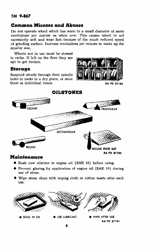
StorageSuspend wheels through their spindleholes in racks in a dry place, or storethem in individual boxes.
OILSTONES
SQUARE TIANGULARTRIANGULAR
ROUND EDGE SLIPRA PD *7183
Maintenance* Soak new oilstone in engine oil (SAE 10) before using.
* Prevent glazing by application of engine oil (SAE 10) duringuse of stone.
* Wipe stone clean with wiping cloth or cotton waste after eachuse.
RA PD 87182
* SOAK IN OIL 0 USE LUBRICANT 0 WIPE AFTER USE
RA PD 87184
8
C4ROLIND

TM 9-867
CleaningWash glazed or "gummed up" stone with dry-cleaning solvent oraqua ammonia. If this treatment fails to completely clean stone,scour it with aluminum oxide abrasive cloth or flint paper attachedto a flat block.
DressingTrue uneven surfaces on coarse, medium, or fine oilstones on side ofan old grinding wheel, a grindstone, or as follows: Cover a smoothcast-iron block with waterproof artificial abrasive paper. Place stoneon surface and lap in with water until true.
NOTE: Special shape stones canbe formed by making a groove ofmating shape in a cast-iron block.Use waterproof artificial abrasivepaper and water and draw stonethrough groove.
Repairing Broken Oilstone
or
0L~'^ -RR^A PDO 87186
Heat pieces on a hot plate todrive all oil from inside stone.
PD 87188
Dust broken edges thickly withflake or ground orange shellac.Carefully work shellac into allcracks and openings.
RA PD 87187
Scrub pieces with dry-cleaningsolvent or aqua ammonia toremove gum and dirt.
; 5 RA PD 87189
Reheat pieces to melt shellac,and clamp together until cooled.Dress stone if joints are uneven.
9
DRESSING OILSTC)

TM 9-867
If shellac is not available, mount broken pieces in wooden block.Cut recess in block, exact size of stone, depth about one-half thethickness of stone. Assemble pieces of stone and force into recessin block.
Common Misuses and AbusesDo not use stone dry. This causes glazing and clogging of stone.Apply engine oil (SAE 10) (or water in an emergency) before usingstone.
RA V RA PDWRONG 87190 RIGHT 87191
Do not store stone in a hot place. Heat will cause oil to form agummy residue on stone. Store in a cool, moist place.
WRONGRA PD 87192
1I ] I - i'
RIGHT
RA PD 87193
Do not attempt to do a honing job with the wrong stone. Such pro-cedure wastes time and energy and causes unnecessary stone wear.Use stones as follows:
STONE USE
Coarse To sharpen large and very dull or nicked tools.
To sharpen ordinary mechanics' tools not requiring fin-Medium ished edge such as tools for working soft wood, cloth,
leather, and rubber.
To sharpen tools requiring a very fine edge such asFine machinists', engravers', instrument workers', and cabinet
makers' tools.
StorageKeep stone clean and moistened with engine oil (SAE 10). If storedin a dry place, keep stone enclosed in a covered box.
10

TM 9-867
Section III
AWLS
FERRULE -.
HANDLE
BLADE
CONE /BRAD AWL /
5 PIECEQ (OO SADDLER'S
SEWING AWL
RA PD 87194
GRINDING AND TEMPERINGGeneralNormal order for reconditioning an awl blade is to harden, grind,and sharpen. Usually all three operations are not needed. Hardenand temper only if tempered part has been broken off, worn, orground away, or if tool has been overheated. Grind after hardeningand tempering, or if blade has lost its shape from repeatedsharpening.
Hardening and TemperingHeat about one and one-half inches of tip of blade to cherry red.Use a gasoline torch, gas furnace, or charcoal fire. Do not overheat.Quench about 3/4 inch of heated tip in clean, cold water to harden.
RA PDHEAT RA PD 87195 QUENCH 87196
Quickly rub hardened end with aluminum oxide abrasive cloth oroilstone to brighten it. Watch color return to tip from heatedportion of blade and quench when light straw color arrives at point.Polish blade with aluminum oxide abrasive cloth and crocus cloth.
11

TM 9-867
Grinding
Grind blade of cone-pointedawl to point. Rotate awl dur-ing grinding to keep point cen-tered. Be careful that the re-volving wheel does not catchthe point and cause damage.Dip blade frequently in wateror wet grind it.
SharpeningKeep point sharp by frequentlygiving it a few strokes on an oil-stone. Rotate cone-pointed awlslightly before each stroke. Donot use too much pressure onthe tool, to avoid ridge markson the surface of the stone.
If grinding a flat-pointed orspecial shaped awl blade, holdblade against abrasive wheel inpositions to preserve or restoreoriginal shape.
RA PD 87199
Replacing Handles· Clamp blade in soft-jawed vise and pull or tap old handle from
shank of blade. Pry ferrule from handle.* Tap ferrule onto new handle. Prick punch ferrule to handle.* Tap handle onto shank of blade and remove blade from vise.
FERRULE WSTALLATION
12
RA PD 87197 RA PD 87198

TM 9-867
Common Misuses* Do not use an awl with a loose handle.
This often results in injury to the user.
Make sure the handle is tight, thus preventing the tang from,injuring the user's hand.
· Do not use the awl with a prying or lever action.This results in breakage.
Exert force toward the point or cutting edge.
StorageDip awl in rust preventive compound (thin film). To protect thepoint of the awl, insert the point into a small cork, a small, shorttwig from a tree, or a soft wood block. Store in a dry place. Protectblade from contact with metals. Upon removal from storage, washmetal parts with dry cleaning solvent to remove rust preventivecompound.
13

TM 9-867
Section IV
BITS AND BORING TOOLS
K BITRA PD 87201
PARTS OF A TWIST DRILL
FLUTE
THE POINTRA PD 87202
14
·-~~~~~~~~~~~I

TM 9-867
GRINDING TWIST DRILLS
GeneralTwist drills may be ground in a drill holder fixture or free hand.Use fixture if available. Both methods are given in the followingpages.
Grind drill lips or cutting edges at anangle of 59 degrees, as illustrated below 0 0(50 to 60 degrees for drilling brass orbronze, 68 degrees for extremely hardmaterial). Both cutting edges mustmake same angle with drill axis, and 590 590both cutting edges must be of samelength. I
RIGHT
12oTO 15°
'-7 10~ 150 RIGHTRA PD 87204
Grind heel to an angle of 12 to 15 de-grees (9 degrees for drilling extremelyhard material). Failure to provide suffiRIGHTcient clearance is the principal cause RA PD 87203of drills splitting up the web.
95
LIPRIGHT ANGLE
RA PD 87205
....... ..._ 15.J.o. u -__ - 6

TM 9-867
Some Common Grinding Faults toGuard Against:
FAULT
Lip angle excessive.
RESULT
Drill will not centerproperly becausecone-shaped point is
WRONG too flat.
Lip angle too small.
WRONG
Point on center butcutting edges groundto different angles.
Cutting edge anglesare equal but lips areof different lengths.
Drills slower and re-quires more powerbecause of longerlength of cuttingedges, and requiresfrequent sharpening.
Only one cutting edgewill do work. This re-
"A sults in rapid drillAND "B" wear and causes holeUNEQUAL to be larger than drill.
A 1B This throws point andlip off center, causing
WRONG strain on drill, ma-chine, and work, and
DISTANCES causing hole to be"A" AND "B' much larger than
/ UNEQUAL drill.
Insufficient heel angleor clearance.
ANGLEUNDER 120
WRON4G
Cutting edges loseeffectiveness. Drillwon't drill and maysplit up center whenpressure is applied.
Excessive heel angleor clearance.
..-c.. l=- Cutting edges likelyto break down due to
WRONG excessive bite with in-RA PD 87206 sufficient support.
16

TM 9-867
Using Drill Holder Fixture*Exact procedure for grinding will vary with make of drill grindingmachine used. General procedure, which applies to conventionaltype machines, is given in the following steps:
Adjust machine to desired cutting edge and heel angles. Referto illustrations of lip angle and heel angle (page 15).
Place drill in V-blocks of holder. Turn so cutting edge will con-tact abrasive wheel as drill is fed into wheel.
Start motor and advance tailstock until drill makes contact withwheel.
Hold drill in place in V-blocks and swing holder spindle slowlythrough its arc. Without changing tailstock adjustment, revolvedrill one-half turn in V-blocks and sharpen other lip of drill insame manner.
_ u- ABRASIVE WHEEL
V-BLOCK
DRILL
:. I -I
Inspect drill point to see if it has been ground back far enough toeliminate all nicks. Repeat grinding and inspection operations untilperfect appearing points are obtained.
Free Hand Grinding1. Adjust tool rest to a convenientheight for resting back of forehand
~'- 6-Ž'V-- on it while grinding.
RA Po 87208
17

TM 9-867
2. Hold drill between thumb and index finger of right or lefthand. Grasp body of drill near shank with other hand.
3. Place forehand on drill rest with centerline of drill makingdesired angle with cutting face of wheel and slightly lower shankend of drill as illustrated.
RESTn /
RA PD 87210
RA PD 87209
4. Slowly place heel of drillagainst grinding wheel. Thengradually raise shank end ofdrill and twist drill in fingersin a counterclockwise directionwhile grinding wheel approachesthe -utting edge. Exert onlyenough pressure to grind thedrill without overheating. Fre- (quently cool drill in water whilegrinding. RA PD 87211
5. Check results of grindingwith a gage to determine if cut-ting edges are same length andat desired angle and if heel isground to angle of 12 to 15degrees.
18
TM 9-867
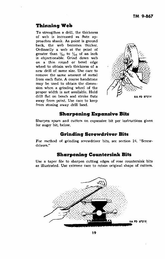
Thinning WebTo strengthen a drill, the thicknessof web is increased as flute ap-proaches shank. As point is groundback, the web becomes thicker. ,
Ordinarily a web at the point ofgreater than 1/32 to 1/16 of an inchis objectionable. Grind down webon a thin round or bevel edgewheel to obtain web thickness of anew drill of same size. Use care toremove the same amount of metalfrom each flute. A coarse handstonemay be used to obtain the dimen-sion when a grinding wheel of theproper width is not available. Holddrill flat on bench and stroke flute / RA PD 87214
away from point. Use care to keepfrom stoning away drill land.
Sharpening Expansive BitsSharpen spurs and cutters on expansive bit per instructions givenfor auger bit, below.
Grinding Screwdriver BitsFor method of grinding screwdriver bits, see section 24, "Screw-drivers."
Sharpening Countersink BitsUse a taper file to sharpen cutting edges of rose countersink bitsas illustrated. Use extreme care to retain original shape of cutters.
RA PD 87215
19

TM 9-867
SHARPENING AUGER BITS
SHANK
AUGER BIT
SCREW SPUR TWIST RA PD 87216
Sharpening Spurs AUGER :
Select an auger bit file or asmall mill file.
RA PD 872'
Hold auger bit against a solid surface with shank downillustrated.
spurs, using care to retainoriginal shape of spur. Stop fil-ing when a fine bur appears oncutting edge of spur. Check todetermine if spurs are equal in
RA PD 87219 length.Remove bur from spurs with a light touch of file. RA PD 872
20
17as
as
220

TM 9-867
Sharpening Cutters
Hold auger bit against a solidsurface with screw of auger bitpointing down.
Lightly file each cutter ontop side. Use care to maintainoriginal chisel-like shape of cut-ting edge.
CUTTINGEDGE
RA PD 87222
Stop filing when a fine burappears on cutting edge.
Check to determine if cuttingedges contact surface of a boardat same level.
RA PD 87221
viT•
CUTTING EDGES
RA PD 87223
Common Misuses to AvoidNever attempt to enlarge alikely to break or bend theor reamer to enlarge hole.
hole by tipping drill sidewise. You aredrill or hurt yourself. Use a larger drill
RA PDWRONG 87224
RA PDRIGHT 87224A
21

TM 9-867
Do not allow drills to overheat while in use or being sharpened.Heating destroys temper and makes tool worthless. Use propercutting oil or compound when drilling metal other than cast iron.Wet grind drills when sharpening.
WRONG RIGHT RA PDR7775
To drive a drill into a socket orsleeve, do not use a steel hammeror other hard object. This woulddamage cutting edges. First makecertain socket or sleeve and drillshank are clean, then tap drill toseat with a lead or brass mallet.
Do not place work-supporting blocksof work will snap off drill. Supportsecurely to prevent turning.
WRONG RIGHT
RA PD 87225A
far from drill. "Springiness"work near drill and clamp
WRONG RIGHT
22
RA PD 87226

TM 9-867
Do not allow drill to workloose in chuck. This willcause "chucking" and willbur or break drill. Keep drilltight in chuck.
RIGHTRA PD 87228
Never keep drills loose in tool boxes. This practice causes unneces-sary dulling of cutting edges. Keep in a rack or divided box whennot in use.
RA PDWRONG RIGHT 87229
StorageCoat bits and drills with rust preventive compound (thin film)and store in a dry place. Use racks or divided boxes to protectcutting edges from contact with metal. Upon removal from storage,wash with dry cleaning solvent to remove rust preventive compound.
23
WRONGRA PD 87227

TM 9-867
Section V
BRACES AND HAND DRILLS
TYPICALBREAST DRILL
4 JAWS
tRATCHET
TYPICAL HAND BRACE
TYPICAL SPIRAL HAND DRILL RA PD 87230
CAREKeep holding screws tight at all times. Loose screws may permitloose meshing of gears. This causes teeth to break.
Do not disassemble chuck except when necessary to make repairs,because of danger of losing springs.
Do not let tool rust. Scour off rust with crocus cloth or finealuminum oxide abrasive cloth. Apply lubricating preservative oil(special) or engine oil (SAE 10) lightly to surfaces which tend torust.
Keep tool lubricated at all times, in accordance with followinginstructions:
24
TYPICALHAND DRILL

TM 9-867
LUBRICATION DATA
TOOL PART LUBRICANT
Cap bearings GREASE, general purpose, No. 0,or GREASE, O.D., No. 0
Handle bearings
Ring and ratchetBrace Ring and ratchet OIL, engine, SAE 10, or OIL,mechanism
lubricating, preservative, specialSleeve and jawmechanism
Gear teeth
Handle bearings OIL, engine, SAE 10, or OIL,Breast and Drill chuck lubricating, preservative, specialhand drills mechanism
Spirals (push GREASE, general purpose, No. 0,type hand drills) or GREASE, O.D., No. 0
Common Misuses and Abuses
WRONGRA D 87231
Do not use tool with bit notfully inserted into chuck.This places a strain on jawsof chuck and may breakdrill. Insert bit fully intochuck. RIGHT
RA PD 87232
Do not use a "squeaking" brace or hand drill. A squeak means toolis wearing. Lubricate before using.
SQUEAK
WRONG RIGHTRA PD 87233
StorageFor permanent storage, wash tool in dry cleaning solvent to removelubricants. Coat all metal parts of tools with rust preventive com-pound (thin film) and store in a dry place where tool will be safefrom accident.
Upon removal from storage, remove rust preventive compoundfrom metal parts by washing with dry cleaning solvent.
25
TM 9-867
Section VI
BRUSHES
PAINT AND VARNISH BRUSHES
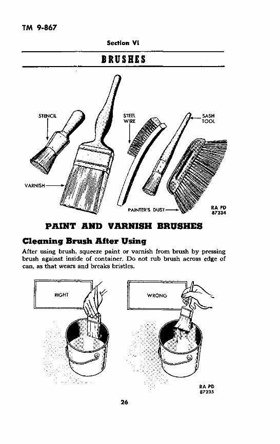
Cleaning Brush After UsingAfter using brush, squeeze paint or varnish from brush by pressingbrush against inside of container. Do not rub brush across edge ofcan, as that wears and breaks bristles.
RA PD87235
26
TM 9-867
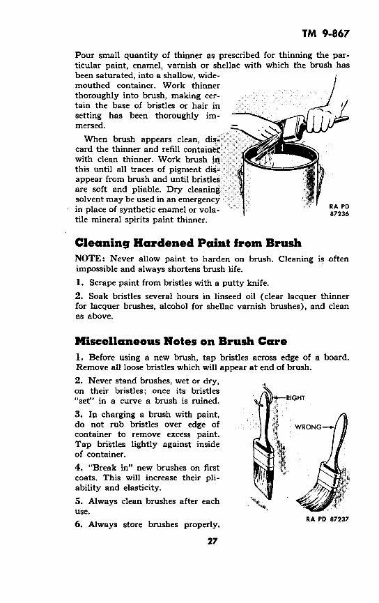
Pour small quantity of thinner as prescribed for thinning the par-ticular paint, enamel, varnish or shellac with which the brush hasbeen saturated, into a shallow, wide-mouthed container. Work thinnerthoroughly into brush, making cer-tain the base of bristles or hair insetting has been thoroughly im- -mersed.
When brush appears clean, dis- fcard the thinner and refill containerwith clean thinner. Work brush inthis until all traces of pigment dis K4iappear from brush and until bristlesare soft and pliable. Dry cleaningsolvent may be used in an emergencyin place of synthetic enamel or vola- 87236tile mineral spirits paint thinner.
Cleaning Hardened Paint from BrushNOTE: Never allow paint to harden on brush. Cleaning is oftenimpossible and always shortens brush life.
1. Scrape paint from bristles with a putty knife.
2. Soak bristles several hours in linseed oil (clear lacquer thinnerfor lacquer brushes, alcohol for shellac varnish brushes), and cleanas above.
Miscellaneous Notes on Brush Care1. Before using a new brush, tap bristles across edge of a board.Remove all loose bristles which will appear at end of brush.
2. Never stand brushes, wet or dry,on their bristles; once its bristles"set" in a curve a brush is ruined. RIGHT
3. In charging a brush with paint,do not rub bristles over edge of WRONGcontainer to remove excess paint.Tap bristles lightly against insideof container.
4. "Break in" new brushes on firstcoats. This will increase their pli-ability and elasticity.
5. Always clean brushes after eachuse.
RA PD 872376. Always store brushes properly.
27

TM 9-867
Overnight Storage1. Drill small hole in handle ofbrush. 1/ _
2. Suspend paint and enamel >*
brushes in linseed oil "keeper"so that bristles and setting are i 2completely submerged, but do t ?not allow bristles to touch bot- WRONG
tom of container.
3. Brushes used with shellac ?5 Ivarnish will be cleaned imme-diately after use, wrapped in Ipaper and kept flat, pending . A P
further use. RA PD 87238
Indefinite Storage1. Clean brush thoroughly and immersein linseed oil. Press out most, but notall, of linseed oil.2. Wrap in oiled paper or brown wrap-ping paper and store flat.
RA PD 87239 3. Once every six months, unwrapbrush and treat with linseed oil.
NOTE: Brushes used with lacquer or shellac varnish can bewrapped in paper and stored dry.
Care DUST BRUSHESBlow dust from brush with compressed air.
Clean soiled or stained brushes with dry cleaning solvent. Presssolvent from bristles and suspend brush by handle until dry.
StorageClean brush and wrap in paper. Store brush in flat position.
Care WIRE BRUSHESClean brushes in dry cleaning solvent and blow dry with com-pressed air.
StorageApply rust preventive compound (light) to bristles. Wrap ingreaseproof wrapping paper and store in a dry place.
Common Misuses and AbusesImproper cleaning and improper storage are the most commonabuses of brushes. Clean and store brushes in accordance withinstructions above.
28
TM 9-867
Section VII
CALIPERS
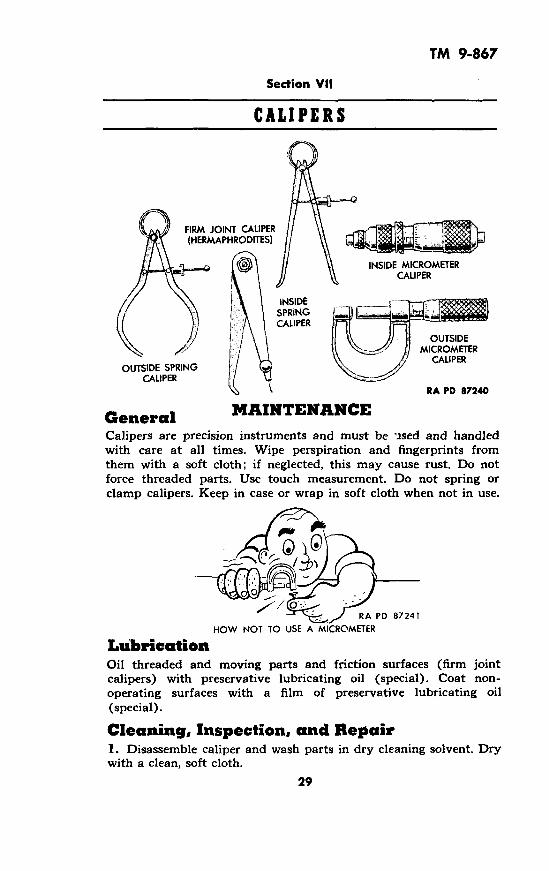
FIRM JOINT CALIPER(HERMAPHRODITES)
INSIDE MICROMETERCALIPER
INSIDESPRINGCALIPER
OUTSIDEMICROMETER
CALIPEROUTSIDE SPRING
CALIPER~,t RA PD 87240
General MAINTENANCECalipers are precision instruments and must be used and handledwith care at all times. Wipe perspiration and fingerprints fromthem with a soft cloth; if neglected, this may cause rust. Do notforce threaded parts. Use touch measurement. Do not spring orclamp calipers. Keep in case or wrap in soft cloth when not in use.
RA PD 87241
HOW NOT TO USE A MICROMETER
LubricationOil threaded and moving parts and friction surfaces (firm jointcalipers) with preservative lubricating oil (special). Coat non-operating surfaces with a film of preservative lubricating oil(special).
Cleaning, Inspection, and Repair1. Disassemble caliper and wash parts in dry cleaning solvent. Drywith a clean, soft cloth.
29

TM 9-867
2. Inspect all threaded parts to be sure all dirt is removed. Scarcelyvisible particles may cause uneven thread motion and binding.
3. Inspect parts to see if they are rusted, corroded, burred, bent,or worn. Scour with crocus cloth to remove rust or corrosion.Replace parts which are bent, broken, or worn.
4. Lubricate parts as instructed above, and reassemble caliper.
Repair Bent Firm Joint or Spring CaliperIf leg is bent, place caliper on soft metal block. Straighten bent legto original shape by tapping with brass hammer. Replace bentadjusting screws.
RATCHET STOP-------
THIMBLE CAP j
THREAD PLAY ADJUSTMENT NUT
FIXED NUT C
MICROMETER SCREW
-THIMBLE
-BARREL
-CLAMP RING .
)TYPICAL
MICROMETERCALIPER
CUTAWAY VIEW
30

TM 9-867
Adjustment of Micrometer CaliperTo compensate for thread wear, screw thimble from barrel. Tightenthread play adjustment nut on fixed nut a fraction of a turn ata time. Test fit of micrometer screw in fixed nut. Repeat tighteningand test until operation is free from both binding and play.
NOTE: Some micrometers have an automatic spring-controlledthread play adjustment.
Testing MicrometerCaliper
1Clean measuring faces with a soft cloth.Examine faces after cleaning and re-move any lint deposited by cleaningcloth.
2
Measure length of micrometer test gageof same length as minimum capacity ofmicrometer. Micrometer should read itsexact minimum capacity. For 0-1 inchmicrometer, screw thimble down untilspindle contacts anvil. Do not forcethimble. Reading should be 0.000 inch.
3
Measure length of a micrometer testgage of same length as maximumcapacity of micrometer. Micrometer RA Pa 87243should read its exact maximum capacity.
Check inside micrometers against outside micrometers or gageblocks.
If in checking it is found that micrometers do not read correctly,refer to proper authority for adjustment.
Never use inaccurate micrometers.
MisusesNever use micrometers with dirty anvil and/or threads.
Dirt on micrometer anvil gives incorrect readings. Dirty threadscause excessive wear and eventually inaccurate readings.
Do not carry micrometers in a pocket of work clothes, as dirtfrom the pocket works into the threads.
Keep micrometers in a covered box on the job and wipe anviland spindle clean with a soft, slightly oiled rag each time afterusing and before returning them to their places in the box. Keepcover closed to protect micrometers from dirt and grinding dust.
835846 0 - 49 - 3 31

TM 9-867
WRONG RIGHTRA PD 87244
Do not check a part that is moving or rotating. Damage to themicrometer and possible injury to the operator will result.
WRONG RIGHT RA PD 87245
StorageWrap in greaseproof wrapping and enclose in a covered box. Storeoughly and apply a film of preservative lubricating oil (medium).Wrap in greaseproof wrapping and enclose in a covered box. Store
in a dry place.
32
-
I
TM 9-867
Section VIII
CHISELS
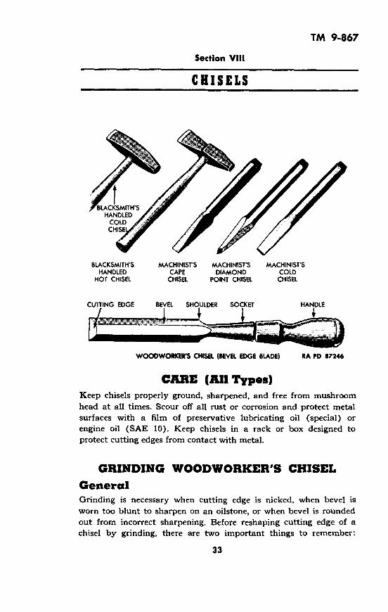
BLACKSMITH'SHANDLED
COLDCHISE
BLACKSMITH'S MACHINIST'S MACHINIST'S MACHINIST'SHANDLED CAPE DIAMOND COLD
HOT CHISEL CHISEL POINT CHISEL CHISEL
CUTTING EDGE BEVEL SHOULDER SOCKET HANDLE
WOODWORKERS CHISEL (BEVEL EDGE BLADE) RA PD 87246
CARE (All Types)Keep chisels properly ground, sharpened, and free from mushroomhead at all times. Scour off all rust or corrosion and protect metalsurfaces with a film of preservative lubricating oil (special) orengine oil (SAE 10). Keep chisels in a rack or box designed toprotect cutting edges from contact with metal.
GRINDING WOODWORKER'S CHISELGeneralGrinding is necessary when cutting edge is nicked, when bevel isworn too blunt to sharpen on an oilstone, or when bevel is roundedout from incorrect sharpening. Before reshaping cutting edge of achisel by grinding, there are two important things to remember:
33
TM 9-867
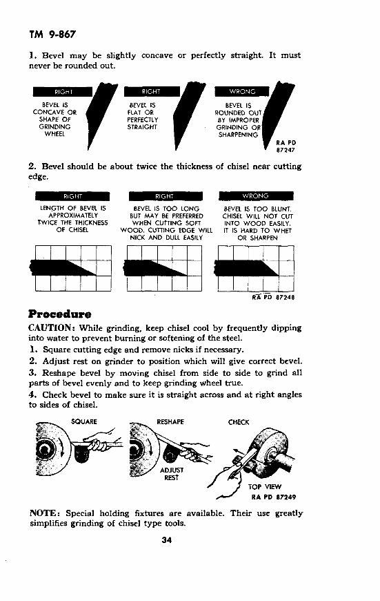
1. Bevel may be slightly concave or perfectly straight. It mustnever be rounded out.
BEVEL ISCONCAVE OR
SHAPE OFGRINDING
WHEEL
9 BEVEL ISFLAT ORPERFECTLYSTRAIGHT
BEVEL ISROUNDED OUTBY IMPROPER
GRINDING ORSHARPENING
RA PD87247
2. Bevel should be about twice the thickness of chisel near cuttingedge.
LENGTH OF BEVEL IS BEVEL IS TOO LONG BEVEL IS TOO BLUNT.APPROXIMATELY BUT MAY BE PREFERRED CHISEL WILL NOT CUT
TWICE THE THICKNESS WHEN CUTTING SOFT INTO WOOD EASILY.OF CHISEL WOOD. CUTTING EDGE WILL IT IS HARD TO WHET
NICK AND DULL EASILY OR SHARPEN
IRC'PD 87248
ProcedureCAUTION: While grinding, keep chisel cool by frequently dippinginto water to prevent burning or softening of the steel.1. Square cutting edge and remove nicks if necessary.2. Adjust rest on grinder to position which will give correct bevel.3. Reshape bevel by moving chisel from side to side to grind allparts of bevel evenly and to keep grinding wheel true.4. Check bevel to make sure it is straight across and at right anglesto sides of chisel.
RESHAPE CHECK
NOTE: Special holding fixtures are available. Their use greatlysimplifies grinding of chisel type tools.
34
U·rl4dine_li�fili I�im

TM 9-867
SHARPENING WOODWORKER'S CHISELWhettingAlways whet chisel after grinding. Once chisel is ground, it can bekept sharpened for a long time by whetting as often as necessary.
1. Clean oilstone and place enough oil on it to wet surface.
2. Place chisel on stone as shown in illustration to obtain correctangle.
3. Hold chisel firmly and moveit back and forth along entirelength of stone.
CAUTION: Avoid wearing agroove in stone. Move chiselevenly over entire stone.
4. Place flat side of chisel onstone as illustrated and removewire edge.
5. Repeat stoning of bevel and RA PD 87250
flat until chisel is sharp.
StroppingFor an extremely keen edge, finish with a few strokes on a leatherstrap, or by stropping first on one side and then on other on asoft wood block.
SOFT WOOD BLOCK _ STROP SIDES ALTERNATELYTEN OR TWELVE TIMES
UNTIL WIRE EDGE ISREMOVED
RA PD 87251
REPAIRING MUSHROOMED HEAD(Woodworkers' Chisel)
MUSHROOMED HEAD
HANDLE
DOTTED LINE SHOWSORIGINAL SHAPE
RA PD 87252
35

TM 9-867
Chisel heads become battered or mushroomed after considerableuse. To make a permanent repair:
1. Remove handle from chisel. Saw handle off at point of contactwith head.
2. Turn end of handle down to about v%6-inch diameter for about3/8 inch.
3. Cut leather or fiber washers to fit snugly over tip cut on endof handle. Be sure outside diameter of washers slightly exceedsoutside diameter of handle. Cut enough washers so their total thick-ness equals or slightly exceeds height of tip on end of handle.
./ RA PDw ? P87253~~~~~~87253
4. Glue washers onto end of handle. Clamp until glue dries.
5. Grind, sand, or cut washers down to conform to shape of handle.
REPLACING HANDLE(Woodworkers' Chisel)
1. Pull old handle from socket. If handle is broken off in socket,drill it out.
2. Shape end of new handle until it is a snug fit in socket.
3. Place blade in soft-jawed vise and tap handle to seat in socket.
MAINTENANCE OF BLACKSMITHS' ANDMACHINISTS' CHISELS
GrindingThe cutting angle of a chisel isdetermined according to the hard-ness and toughness of the mate-rials being cut. An included cut-ting edge angle-of 70 degrees doeswell for most work. While chiselsused on hard or tough metal re-quire greater strength backing upthe cutting edge, an angle up to90 degrees may be used for thispurpose. The cutting angle can bedecreased somewhat from 70 de-grees for cutting softer metals.
36
ANGLE "A" ISUSUALLY 700.
IT IS SOMETIMESGROUND AT
UP TO 90 ° FORCUTTING EXTREMELY
HARD METAL
CUTTINGEDGE
SLIGHTLYCURVED
RA PD 87254

TM 9-867
Set rest to secure desired bevel angle. Move chisel head from sideto side a little during grinding to slightly curve cutting edge. Turnchisel over to grind other bevel. Keep bevels same size or cuttingedge will not be centered. Dip chisel frequently in water to pre-serve temper. NOTE: After several grindings, cutting end of chiselmay be too thick. Such chisels can be heated and reforged, tem-pered, and ground.
Hardening and TemperingMachinists' ChiselsHeat whole chisel to cherry red in a gas furnace or charcoal fire.Grasp chisel in center with tongs. Dip cutting end in clear, coldwater to a depth of about 1Y4 inch. Turn chisel over and dip headend about 1 inch. Quickly polish hardened ends with a file, oraluminum oxide abrasive cloth. Watch color return from heatedcenter section of chisel to ends. Redip cutting end every time endbecomes purple. Redip head end every time it becomes blue. Whenred disappears from chisel, dip whole tool.
CHISEL I TONGS
GRASP CHERRY REDWATER IN CHISEL IN CENTER
WELL FILLED 1 . 0 AND DIP STRAIGHTCONTAINER DOWN
RA PD 87255
Removing Mush-roomed End FromMachinists' ChiselsIt is dangerous to use a metal-cutting chisel with a mush-roomed head. Grind head tooriginal shape. Harden chisel RA PDafter removing mushroom. 87256
Replacing Handles on Blacksmiths' ChiselsFollow procedure given under Hammers, Mallets, Mauls, andSledges (section 12).
Common Misuses and AbusesDrawing temper or burning during sharpening.
Exerting too much pressure against the wheel during sharpening
37

TM 9-867
causes excess heat at the cutting edge of the chisel. When and if thetemperature of the cutting edge goes above the temper drawingheat, it causes the cutting edge to lose the hardness required forcutting edges. If the cutting edge of the chisel colors to blue or paleblue, the loss of temper has taken place. Exerting light pressure andfrequent cooling in water while grinding is the proper preventivemaintenance. If the cutting edge becomes too soft due to too muchheat in grinding or too frequent grinding, the chisel must be hard-ened and the temper drawn in order to restore the proper hardness.
Storage (All Types of Chisels)Apply rust preventive compound (thin film) to chisels before stor-age and protect cutting edge from contact with metal or abrasives.Store in a dry place. After removal from storage, wash metal partswith dry cleaning solvent to remove rust preventive compound.
38

TM 9-867
Section IX
CLAMPS
TOOLMAKER'SCLAMP
HYDRAULIC BRAKE CLAMPRA PD 87257
MAINTENANCE
General-All ClampsThese are relatively heavy-duty but simple tools. Maintenancerequirements are few:
Keep screws lubricated with small quantity of preventive lubri-cating oil (special) or engine oil (SAE 10). Excessive lubricantinterferes with use of tool. Keep metal surfaces free of rust. Scouroff rust or corrosion with crocus cloth or aluminum oxide abrasivecloth. Coat surfaces with preservative lubricating oil (special) orengine oil (SAE 10).
Varnish hardwood jaws of hand screw clamps whenever finishbecomes damaged extensively enough to leave wood without protec-tive coating.
Replace all parts broken or damaged beyond repair.
LUBRICATESCREWS
REMOVERUST
VARNISHWOOD
RA PD 87258
39

TM 9-867
Replace C-Clamp Screw or Jaw1. Pry open crimped portion of swivel head and remove head fromball on end of screw. Turn the screw out of iaw.
C-CLAMPDISASSEMBLED
2. Using new parts as needed, turn the screw into position throughits boss at end of jaw. Slip swivel head onto ball on end of screwand crimp head sufficiently to hold it on ball.
Replace Handle on Hand Screw Clampor Toolmaker's ClampFile off peened ends of pin which attaches handle to screw. Driveout pin. Unscrew or drive handle from screw. Screw new handle inposition on screw with pinholes in handle and in screw alined. Tapin and peen pin.
Replace Jaw, Screw or Insert onHand Screw Clamp or Toolmaker's Clamp1. Remove handles in accordance with instructions above. Turnboth screws from the two jaws. Lift inserts (if any) from jaws.
-JAW JAW-
SCREWS
_ -:90MU gf~
INSERT
iHANDLE
3 ---- PIN- INSERT
RA PD 87260
2. Using new parts as necessary, place inserts (if any) in positionin jaws. Turn both screws into position in the two jaws. Installhandles on screws.
40
PIN
t AHANDLEA
RA PD 87259

TM 9-867
Common Misuses and AbusesDo not use a wrench or bar in tightening clamps. Too muchpressure may warp, bend, or break them. Tighten clamps by hand.When applying great pressure, observe clamps for indication ofundue strain.
WRONG RIGHT
RA PD 87261
Do not cock clamp to tighten. This procedure may warp, bend,or break clamps. Keep jaws parallel.
RA PDWRONG RIGHT 87262
Storage (All Clamps)Coat clamps with rust preventive compound (thin film) and storein a dry place. After removal from storage, wash metal parts withdry cleaning solvent to remove rust preventive compound.
41

TM 9-867
Section X
DIVIDERS
SPRING DIVIDERS
WING DIVIDERS
RA PD 87263
MAINTENANCEGeneralWipe fingerprints and moisture from dividers after use to preventrusting or corroding. Keep in case or wrap in soft cloth when notin use.
LubricationOil threads, pivots, and other surfaceslubricating oil (special).
Sharpening PointsSharpen divider points with asmall oilstone moistened withlight oil. Keep points towardinside of legs so points willmeet when dividers close. Holddividers stationary and strokewith stone. Give stone a slightrotating movement to preventflat spots.
Installing Pivot onSpring DividersInsert a block between legsabove screw. Squeeze legs to-gether to spread spring.
sparingly with preservative
RA PD 87264
42
TM 9-867
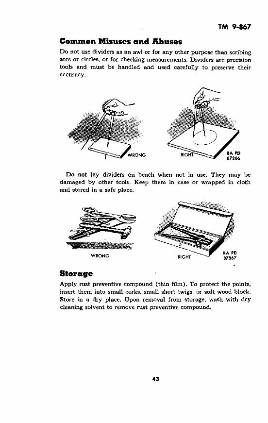
Common Misuses and AbusesDo not use dividers as an awl or for any other purpose than scribingarcs or circles, or for checking measurements. Dividers are precisiontools and must be handled and used carefully to preserve theiraccuracy.
WRONG ~~~~~~RA PD87266
Do not lay dividers on bench when not in use. They may bedamaged by other tools. Keep them in case or wrapped in clothand stored in a safe place.
RA PDWRONG RIGHT 87267
StorageApply rust preventive compound (thin film). To protect the points,insert them into small corks, small short twigs, or soft wood block.Store in a dry place. Upon removal from storage, wash with drycleaning solvent to remove rust preventive compound.
43

TM 9-867
Section XI
FILES AND RASPS
-HANDLE
TANG .- FERRULE
HEEL
EDGE
FACE
FLAT
V_• - HALF RA PDPOINT ROUND TAPER ROUND 87268
Care MrAINTENANCEPreserve sharpness of files. Keep them in a rack. If necessary tocarry files in a tool box, wrap them individually in cloth or paper.Keep files dry to prevent rusting. Do not use rust preventive com-pound. Do not abuse files. They are brittle and extremely dangerousif hammered or used as pry bars.
Installing HandleCAUTION: It is dangerous to use a file without a handle.
1. Select handle to fit tang. If neces-sary to use handle having hole toosmall for tang, heat same size tangof an old file and insert in handle toburn hole to proper size (snug fit).
2. Wet tang of file and insert it in han-dle. Tap back end of handle on a flatsurface until file is properly seated.Do not hammer file into the handle.
NOTE: Several types of "screw-on"handles are available. If using handleof this type, install as directed by _handle manufacturer. RA PD 87269
44

TM 9-867
Removing HandleHold file with left hand. Holdhandle with right hand. Pull file
from handle while rapping ferrule
end of handle against edge of
bench. '!!!!/
NOTE: If removing "screw-on"
type handle, remove in accord- RA PDance with handle manufacturer's - 87270instructions.
Cleaning Files1. The cutting action of a fileproduces small particles or chips FILINGS
called filings. These particles fre- ~WORKquently wedge between the teeth RA PD 87271of file and impair the free cuttingaction. Frequent cleaning isnecessary to obtain maximumefficiency of file. BRU
MOTION PARALTO TEETH
2. Brush filings from betweenteeth of file with wire brush. Pushbrush in a direction parallel withteeth.
· *~~ · " ~~~~ RA PD87272
3. Remove remaining particles from teeth by using a narrow strip
of soft metal such as brass or copper. A soft metal will not damageteeth.
CLEANING PIN(SOFT METAL)
45
TM 9-867
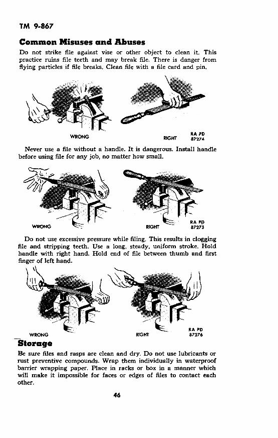
Common Misuses and AbusesDo not strike file against vise or other object to clean it. Thispractice ruins file teeth and may break file. There is danger fromflying particles if file breaks. Clean file with a file card and pin.
RA PDWRONG RIGHT 87274
Never use a file without a handle. It is dangerous. Install handlebefore using file for any job, no matter how small.
,k-E:- RA PDRIGHT 87275
Do not use excessive pressure while filing. This results in cloggingfile and stripping teeth. Use a long, steady, uniform stroke. Holdhandle with right hand. Hold end of file between thumb and firstfinger of left hand.
\\~~~~~ ,-
RA PDWRONG RIGHT 87276
StorageBe sure files and rasps are clean and dry. Do not use lubricants orrust preventive compounds. Wrap them individually in waterproofbarrier wrapping paper. Place in racks or box in a manner whichwill make it impossible for faces or edges of files to contact eachother.
46

TM 9-867
Section XII
HAMMERS, MALLETS, MAULS, and SLEDGES
HAMMER HAMMER
BALL-PEEN SOFT METAL ORHAMMER PLASTIC HAMMER
PLAIN FACED RIVETINGCLAW HAMMER HAMMER
WOODEN DOUBLE FACEMALLET SLEDGE
CAIGeneral
DING WEIGHTHAMMER
TRIMMER'SHAMMER
CROSS PEENSLEDGE
BELL-FACED CLAW HAMMER
STRAIGHT PEENSLEDGE
RUBBERMALLET
RA PD 87277
tE OF HEADS
Prevent rust formation by carefully wiping steel hammer heads dryafter exposure to moisture. When it is known in advance that toolwill be exposed to moisture, spread a film of preservative lubricatingoil (special) or engine oil (SAE 10) over head.
47835846 0 - 49 - 4

TM 9-867
Frequently inspect hammer type tools to see if handle is tightin head and to see if face is in satisfactory condition.
Replacing Handle1. Remove old handle fromhead. If handle is tight, sawoff old handle next to neck ofhammer head. Do not saw thehandle off so close to the headthat the saw teeth will touchthe head while sawing, thusdamaging the set of the saw.A hacksaw may also be used.
2. Drill a hole in old handleas illustrated.
3. Drive old handle from headand secure wedges. (Note posi-tion of wedges.)
4. Shape new handle to fithead. Use rasp or spoke shave.
5. Insert new handle to headto determine fit.
6. Assemble for tight fit bystriking end of handle withmallet to seat head firmly onhandle.
RA PD 87278
48
-�'�eo
� 11I

TM 9-867
7. Check results to determine ifhandle fits properly.
8. Saw off the projecting por-tion of handle close to hammerhead and cut slits for wedges.Avoid having saw teeth touchthe head during sawing.
9. Drive wedges into handle. Ifwooden wedges are used, re-place old wedges or make newones from straight grain softwood.
.1
RA PD 87279
10. File or grind end of handle even with head. Use wood rasp ifwooden wedges are used. Grinding may be employed if metalwedges are used.
RA PD 87280
Tightening HandleIf wedge comes loose, remove it and install larger wedge. If wedgeremains tight in handle, but handle loosens, drive thin hardwood oriron wedge into handle beside original wedge. A loose handle can betemporarily repaired by soaking in water. If unable to tighten,replace handle.
Grinding FaceIncorrect or abusive use of hammer type tools frequently results inuneven face wear. To reshape worn faces:
49
= --
anmr-

TM 9-867
1Determine if face should be plainor bell shaped by examining un-worn portion of face or by com- WORNparing with unworn tool of same FACEtype.
2Grind face to original shape. Fre-quently immerse head in waterto prevent burning. Do not re-move more stock than necessary.
3 RESTORED
On mallet type tools, grind equal FACE
amount of material from bothfaces to preserve balance.
RA PD 87281
Common MisusesDo not strike a hardened steel surface with a hammer.
This misuse is a serious safety hazard. Small pieces of sharp,hardened steel break from the hammer and also from the hardenedsteel. This has been responsible for many serious eye injuries. Itmay also cause damage to the work and/or the hammer.
Use a soft hammer in striking any hardened steel. If a softhammer is not available, place a piece of copper, brass, fiber, orwood on the hardened steel. Strike the soft material and not thehardened steel.
StorageCoat steel heads with rust preventive compound (thin film) andstore in a dry place. Upon removal from storage, wash metal partswith dry cleaning solvent to remove rust preventive compound.
50
TM 9-867
Section XIII
HAND GRINDERS
1L
ENCLOSEDGEAR CASE(OIL TIGHT)
RA PD 87282
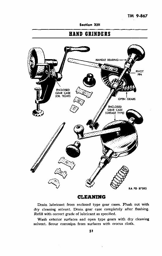
CLEANINGDrain lubricant from enclosed type gear cases. Flush out with
dry cleaning solvent. Drain. gear case completely after flushing.Refill with correct grade of lubricant as specified.
Wash exterior surfaces and open type gears with dry cleaningsolvent. Scour corrosion from surfaces with crocus cloth.
51
TM 9-867
LUBRICATIONLubricate grinders in accordance with following chart:
PART LUBRICATION LUBRICANTPART PERIOD LUBRICANTPERIOD
Enclosed gear cases Weekly OIL, engine, SAE 30(oiltight)
Enclosed gear cases Weekly GREASE, general purpose,(grease type) No. 0
Open gears DailyOIL, engine, SAE 10, or OIL,
Handle bearings Daily lubricating, preservative,
Pivot pins Daily special
Exterior nonwearing OIL, lubricating, preserva-surfaces tive, special
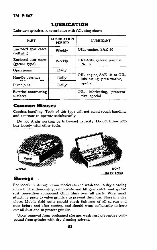
Common MisusesCareless handling. Tools of this type will not stand rough handlingand continue to operate satisfactorily.
Do not strain working parts beyond capacity. Do not throw intobox loosely with other tools.
WRONG RGHTRA PD 87283
StorageFor indefinite storage, drain lubricants and wash tool in dry cleaningsolvent. Dry thoroughly, relubricate and fill gear cases, and spreadrust preventive compound (thin film) over all parts. Wire smallattaching parts to valve grinders to prevent their loss. Store in a dryplace. Mobile field units should check tightness of all screws andnuts before and after storing, and should wrap sufficiently to keepout all dust and to protect grinder.
Upon removal from prolonged storage, wash rust preventive com-pound from grinder with dry cleaning solvent.
52

TM 9-867
Section XIV
HATCHETS, AXES, MATTOCKS, ADZES, and SHOVELS
BROAD HATCHET
4MATTOCK CARPENTER'S ADZE SHIP ADZE SHOVEL
RA PD 87284
Hatchets and Axes1
Remove nicks by holding hori-zontally against abrasive wheel.Move back and forth acrossstone.
2Grind cutting edge of hatchetto bevel indicated. Grind ax asdescribed below. Frequently coolin water to preserve temper.Move from side to side acrossface of grinding wheel.
53
GRINDING
REMOVE NICKSBY GRINDING
RA PD 87285

TM 9-867
AdzesRemove handle and grind to CORRECT HATCHET BEVELSsame level as when grinding ahatchet to hew to a line. Bevelon handle side only.
MattocksFollow procedure for grindinghatchet, and grind to originalbevel.
Correct Ax BevelsCareless grinding will ruin anyax by either destroying the RA PDtemper through heat caused by 87286
friction, or by making the edge FOR GENERAL FOR HEWING
so thin it will not stand up under USE TO A LINE
the force of a swinging blow. Do not use a high speed dry grindingwheel. An ax ground on a dry wheel will surely be ruined. Grindslowly on a wheel kept very wet.
When regrinding, start to grind from 2 to 3 inches back from thecutting edge and grind to about /2 inch from edge. Work for fan-shape effect, leaving reinforcement at corners adequate for suffi-cient strength. Then "roll off" on a convex bevel as shown in thecross-section illustration of an axbit at right. This illustration is CORRECT AXE BEVELS
exact gage "life size" and shapeof properly ground cutting edge. __
Remove all .scratches with GROUND WITH
whetstone or hone. A scratch on CONVEXhighly tempered steel will fre- _ - _quently cause material to break RIGHT
where it is scratchedr
GROUND GROUNDCONCAVE _ _ _ STRAIGHT
WRONG WRONG
RA PD 87287
The illustration above shows This illustration shows the cutthe most frequent mistake in ting edge ground with a longregrinding. It is ground con- straight bevel, better than thecave-the wrong way-leaving concave bevel, but still withoutinsufficient support behind the sufficient reinforcement back ofedge to withstand any ordinary the edge.blow. It will break very easily.
54
TM 9-867
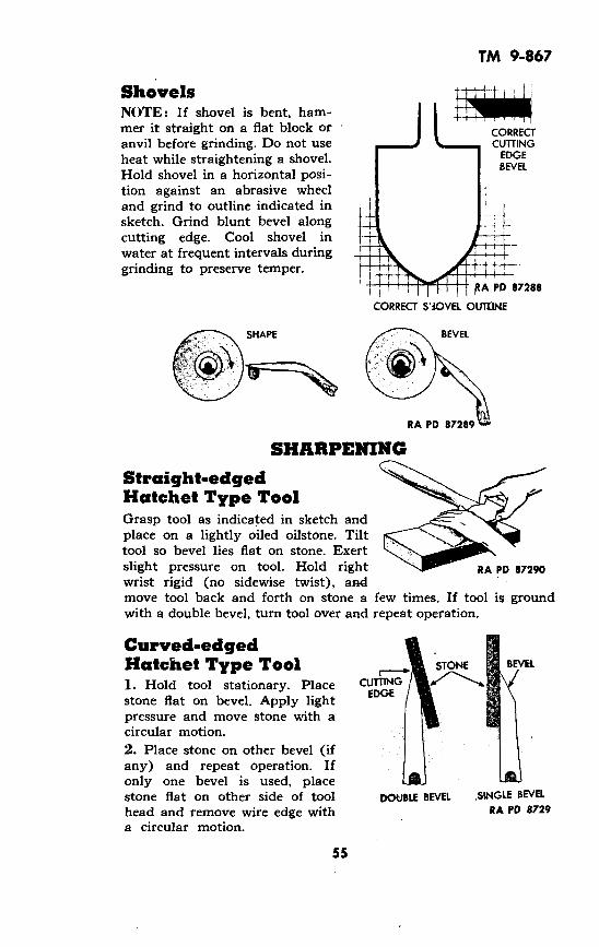
ShovelsNOTE: If shovel is bent, ham-mer it straight on a flat block oranvil before grinding. Do not useheat while straightening a shovel.Hold shovel in a horizontal posi-tion against an abrasive wheeland grind to outline indicated insketch. Grind blunt bevel alongcutting edge. Cool shovel inwater at frequent intervals duringgrinding to preserve temper.
CORRECTCUTTING
EDGEBEVEL
PA PD 87288
SHARPENING
Straight-edged `Hatchet Type ToolGrasp tool as indicated in sketch andplace on a lightly oiled oilstone. Tilttool so bevel lies flat on stone. Exertslight pressure on tool. Hold right RA PD 87290wrist rigid (no sidewise twist), andmove tool back and forth on stone a few times. If tool is groundwith a double bevel, turn tool over and repeat operation.
Curved-edgedHatchet Type Tool1. Hold tool stationary. Placestone flat on bevel. Apply lightpressure and move stone with acircular motion.2. Place stone on other bevel (ifany) and repeat operation. Ifonly one bevel is used, placestone flat on other side of toolhead and remove wire edge witha circular motion.
STONE BEVEL
CUTTING aEDGE
DOUBLE BEVEL SINGLE BEVELRA PD 8729
55
TM 9-867
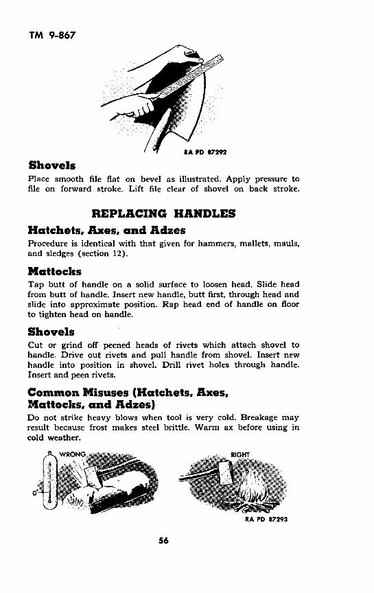
RA PD 87292
ShovelsPlace smooth file flat on bevel as illustrated. Apply pressure tofile on forward stroke. Lift file clear of shovel on back stroke.
REPLACING HANDLESHatchets, Axes, and AdzesProcedure is identical with that given for hammers, mallets, mauls,and sledges (section 12).
MattocksTap butt of handle on a solid surface to loosen head. Slide headfrom butt of handle. Insert new handle, butt first, through head andslide into approximate position. Rap head end of handle on floorto tighten head on handle.
ShovelsCut or grind off peened heads of rivets which attach shovel tohandle. Drive out rivets and pull handle from shovel. Insert newhandle into position in shovel. Drill rivet holes through handle.Insert and peen rivets.
Common Misuses (Hatchets, Axes,Mattocks, and Adzes)Do not strike heavy blows when tool is very cold. Breakage mayresult because frost makes steel brittle. Warm ax before using incold weather.
WRONG
= _i -e I
RA PD 87293
56
"
I

TM 9-867
Do not use tools as mauls or wedges. Breakage across or underthe eye often results. Use tools only for use intended.
WRONG RIGHT
RA PD 87294
Common Misuses (Shovels)Do not use shovel as a pry bar. Handles break easily. Avoid unduestrain on handle.
A L
WRONG RA PD 87295
Never returnwill harden andafter using.
shovel to storage without proper cleaning. Dirtshovel will rust. Always clean shovels thoroughly
StorageCoat metal surfaces with rust preventive compound (thin film) andstore in a dry place in racks or boxes with cutting edges protected.Upon removal from storage, wash rust preventive compound frommetal parts with dry cleaning solvent.
57

TM 9-867
Section XV.
HYDROMETERS
III
StorageStore in a cool place protecte,from direct sunlight. Wrap float i:lens tissue paper and pack hydrometer securely to prevent damage
58
CleaningWash body and float with soapand water. Use care when wash-ing float to keep from injuringmarkings. Battery acid depositswhich do not yield to soap andwater, can be removed with asolution of hot water and soda.
Care in UseProvide a well-protected con-tainer positioned in a handyplace near battery bench.Handle with extreme care andreplace to storage position whennot in use. Clean grease frombulb and tip with carbon tetra-chloride or soap and water.Flush with water and wipe dry.
dn
RA PD87297
I

TM 9-867
Section XVI
KNIVES
FOLDING HANDLE DRAW KNIFE
RA PD 87298
GRINDINGNOTE: Do not grind small knives such as saddler's or electrician'sknives except to shape a broken blade. Sharpen them on an oilstone.
Putty KnifeHold knife perpendicularlyagainst edge of abrasive wheel TOP VIEW
to "square up" worn blade. Dipin water often to preserve SIDE VIEW
temper. Keep blade at rightangles to surface of wheel and
move from side to side duringgrinding.
Do not grind away more stockthan necessary. Remove wireedge and smooth end on oil-stone.
59

TM 9-867
Draw KnifeA draw knife may be ground with a single bevel or a double bevel.Grind to same bevel as originally ground as revealed by inspectionof unworn portions at ends of cutting edge. Bevels may be straightor slightly concave. Never grind bevels convex. Make bevel approxi-mately twice the width of blade at point where bevel starts.Grinding procedure follows:
1. Adjust rest at midpoint ofwheel. Run knife back and forthfull length of blade maintainingoriginal shape, until nicks areremoved.
2. Adjust rest toward top ofwheel to provide correct bevel.Run knife back and forth fulllength of blade until bevel issecured.
3. If double bevel is sought, turnknife over and grind second bevel.CAUTION: Be sure to dip knifein water frequently to preventburning and subsequent loss oftemper.
RIGHTSTRAIGHT
BEVEL
RIGHT
CONCAVEBEVEL
WRONG
CONVEXBEVEL
CORRECT BEVEL LENGTH
RA PD 87300
RESTORE BEVEL
RA PD87301
SHARPENINGSmall KnivesSharpen on a medium or fine oil-stone moistened with a few dropsof oil. Apply blade to stone withback tilted slightly from stone. Holdblade obliquely across face of stoneand rub briskly back and forth.Repeat on other side of blade. Re-move wire edge by stropping on apiece of leather or canvas.
60
:: :y'DE $ f^ iti C? A_;-
RA PD 87302
68�

TM 9-867
Draw KnifePlace a medium or fine oilstone on a block sufficiently high tocause draw knife's handles to clear bench. Moisten oilstone with afew drops of clean light oil. Place knife blade on stone and tiltknife so bevel lies flat on stone. Rub blade on stone in a circularmotion so entire length of bevel contacts stone. If blade has adouble bevel, turn knife over and repeat operation. Remove wireedge by stropping on a piece of leather or canvas.
RA PD 87303
Common MisusesDo not use tool with prying or lever action.
Blade ends and/or sharp thin edges will break if strained beyondbreaking point.
Undue straining will loosen rivets and joints.Handle carefully and use only for purposes intended.
StorageCoat all metal parts of knives with rust preventive compound(thin film) at time of storing. Store in a dry place with cuttingedges protected from contact with metals or abrasives. Uponremoval from storage, wash metal parts with dry cleaning solventto remove rust preventive compound.
61

TM 9-867
Section XVII
LEVELS
5
PLUMB LEVEL
STRIDING LEVEL
RA PD 87304
CARE OF LEVELSTest1. Place level on a true horizontal surface and note level indication.Reverse level end for end. If bubble appears on one side of hairlineon first reading and on other side for second reading, level is outof adjustment.
A B
B 1. LEVEL TEST A
2. Place plumb level against atrue vertical -surface and noteplumb reading. Twist level one-half turn about its vertical axisand again take reading. If bubbleappears on opposite sides of hair-line in the two readings, plumblevel is out of adjustment.
2.PLUMB
TEST
RA PD87305
62
A I
F�
TM 9-867
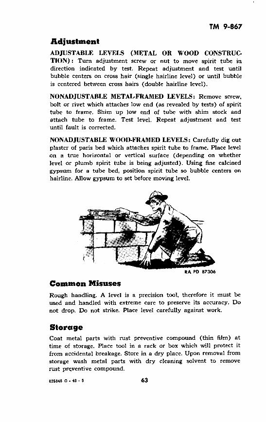
AdjustmentADJUSTABLE LEVELS (METAL OR WOOD CONSTRUC-TION): Turn adjustment screw or nut to move spirit tube indirection indicated by test. Repeat adjustment and test untilbubble centers on cross hair (single hairline level) or until bubbleis centered between cross hairs (double hairline level).
NONADJUSTABLE METAL-FRAMED LEVELS: Remove screw,bolt or rivet which attaches low end (as revealed by tests) of spirittube to frame. Shim up low end of tube with shim stock andattach tube to frame. Test level. Repeat adjustment and testuntil fault is corrected.
NONADJUSTABLE WOOD-FRAMED LEVELS: Carefully dig outplaster of paris bed which attaches spirit tube to frame. Place levelon a true horizontal or vertical surface (depending on whetherlevel or plumb spirit tube is being adjusted). Using fine calcinedgypsum for a tube bed, position spirit tube so bubble centers onhairline. Allow gypsum to set before moving level.
RA PD 87306
Common MisusesRough handling. A level is a precision tool, therefore it must beused and handled with extreme care to preserve its accuracy. Donot drop. Do not strike. Place level carefully against work.
StorageCoat metal parts with rust preventive compound (thin film) attime of storage. Place tool in a rack or box which will protect itfrom accidental breakage. Store in a dry place. Upon removal fromstorage wash metal parts with dry cleaning solvent to removerust preventive compound.
63835846 0 - 49 - 5
TM 9-867
Section XVIII
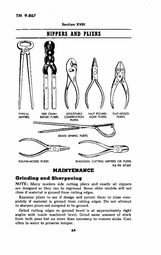
NIPPERS AND PLIERS
! 0 A t
TYPICAL TIRE CHAIN ADJUSTABLE HALF ROUND- FLAT-NOSEDNIPPERS REPAIR PLIERS COMBINATION NOSE PLIERS PLIERS
PLIERS
BRAKE SPRING PLIERS
ROUND-NOSED PLIERS DIAGONAL CUTTING NIPPERS OR PLIERSRA PD 87307
MAINTENANCE
Grinding and SharpeningNOTE: Many modern side cutting pliers and nearly all nippersare designed so they can be reground. Some older models will notclose if material is ground from cutting edges.
Examine pliers to see if design will permit them to close com-pletely if material is ground from cutting edges. Do not attemptto sharpen pliers not designed to be ground.
Grind cutting edges so ground bevel is at approximately rightangles with inside machined bevel. Grind same amount of stockfrom both jaws but no more than necessary to remove nicks. Cooloften in water to preserve temper.
64

TM 9-867
CORRECTLY GROUND CUTTING EDGESNOTE: Jaws on some pliers will not open wide enough to permitgrinding. On such pliers, press out recessed taper pin or removespecial bolt and nut which attach the two halves of pliers togetherand separate jaws for grinding. Peen pin well when assemblingpliers which are pinned together.
CleaningWash pliers in dry cleaning solvent and wipe dry with a cleancloth. Clean dirt from serrated jaw faces with a wire brush. Whencompletely dry, lubricate pivot pin with one or two drops ofpreservative lubricating oil (special) or engine oil (SAE 10).
Renewing Jaw Face SerrationsPlace the pliers in a vise protectedwith soft jaws and renew serrationwith a four- or five-inch three-cornered file. If the jaws of thepliers can be separated and themechanic has access to a small sur-face grinder, new serrations can beground. Diamond dress a narrowwheel to an included angle of 60 RA PD 87309
degrees (30 degrees on each side of centerline) and grind theserrations with each jaw held separately in a grinding vise.
GRINDING WHEEL
65

TM 9-867
Common Misuses
Do not use pliers on a nut.This batters nut and plier jawserrations unnecessarily. Use awrench on nuts.
Do not use pliers as a pry bar.Handles may bend or break.Use tools only for purpose forwhich they are designed.
WRONG
WRONG
RA PD 87311StorageAt time of storage, apply rust preventive compound (thin film).Store in a dry place. Upon removal from storage, wash with drycleaning solvent to remove rust preventive compound.
66

TM 9-867
Section XIX
PLANES
GRINDING PLANE IRONSGeneralIrons must be ground when cutting edge is nicked, when bevel isworn too blunt, when bevel is rounded out, or when cutting edgeis worn to improper shape.
1. Cutting edges should be straight on smooth and block planeirons, slightly curved on jack plane irons, andon fore plane irons.
very slightly curved
SMOOTH ORBLOCK PLANE IRON
, tROUND CUTTING EDGE
CORNERS PERFECTLYSLIGHTLY STRAIGHT
FORE PLANEIRON
90X1 32 IN.0 i
tCUTTING EDGE VERY
SLIGHTLY CURVED(1/32 IN. BULGE)
JACK PLANEIRON
90 1 16 IN. 90'
CUTTING EDGE CURVEDSLIGHTLY
(1/16 IN. BULGE)RA PD 87313
67
TM 9-867
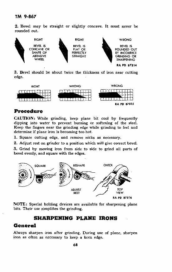
2. Bevel may be straight or slightly concave. It must never berounded out.
RIGHT RIGHT WRONG
BEVEL IS BEVEL IS BEVEL ISCONCAVE OR FLAT OR ROUNDED OUT
SHAPE OF PERFECTLY BY INCORRECTABRASIVE STRAIGHT GRINDING OR
WHEEL SHARPENING
RA PD 87314
3. Bevel should be about twice the thickness of iron near cuttingedge.
RIGHT WRONG WRONG
RA PD 87315
ProcedureCAUTION: While grinding, keep plane bit cool by frequentlydipping into water to prevent burning or softening of the steel.Keep the fingers near the grinding edge while grinding to feel anddetermine if plane iron is becoming too hot.1. Square cutting edge, and remove nicks as necessary.2. Adjust rest on grinder to a position which will give correct bevel.3. Grind by moving iron from side to side to grind all parts ofbevel evenly, and square with the edges.
SQUARE RESHAPE CHECK
ADJUST TOPREST VIEW
RA PD 87316
NOTE: Special holding devices are available for sharpening planebits. Their use simplifies the grinding.
SHARPENING PLANE IRONSGeneralAlways sharpen iron after grinding. During use of plane, sharpeniron as often as necessary to keep a keen edge.
68

TM 9-867
Procedure1. Grasp iron with both hands, palms downward. Place iron bevelon lightly oiled stone with iron at bevel angle.
2. Apply light pressure to iron and rub back and forth over surfaceof stone. Do not alter angle of iron to stone during process. Roundoff corners enough to allow for depth of cut.
3. After whetting bevel side, turn iron over and hold perfectly flaton stone. Give it two or three strokes to remove wire edge.
BEVELFLAT ON
STONE
WHETTING BEVEL REMOVING WIRE EDGE RA PD 87317
Regrinding Chip CapThe chip cap is made of soft steel and the sharp edge is easilydented or marred, thus requiring regrinding.
1. Separate the chip cap and plane iron and remove the chip capscrew.
2. Grind the lower surface of the curved end on the side of agrinding wheel.
_ _, :: .< , i a 13 JTOP VIEW
END VIEW
RA P 87310RA PD 87318
69
TM 9-867
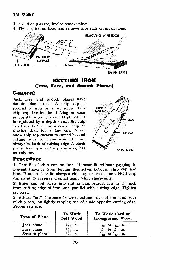
3. Grind only as required to remove nicks.4. Finish grind surface, and remove wire edge on an oilstone.
REMOVING WIRE EDGE
ABOUT 100 /
FSHING$ -~' SURFACE
ALTERNATE
RA PD 87319
SETTING IRON(Jack, Fore, and Smooth Planes)
GeneralJack, fore, and smooth planes havedouble plane irons. A chip cap issecured to iron by a set screw. This DOUBLE
chip cap breaks the shaving as soon PLANE IRtN
as possible after it is cut. Depth of cutis regulated by a depth screw. Set chip IRON
cap back farther for a coarse chip orshaving than for a fine one. Never CHP CAP
allow chip cap corners to extend beyondHIP CAPcutting edge of plane iron; it mustalways be back of cutting edge. A blockplane, having a single plane iron, has RA PD 87320
no chip cap.
Procedure1. Test fit of chip cap on iron. It must fit without gapping toprevent shavings from forcing themselves between chip cap andiron. If not a close fit, sharpen chip cap on an oilstone. Hold chipcap so as to preserve original angle while sharpening.2. Enter cap set screw into slot in iron. Adjust cap to /4 inchfrom cutting edge of iron, and parallel with cutting edge. Tightenset screw.3. Adjust "set" (distance between cutting edge of iron and edgeof chip cap) by lightly tapping end of blade opposite cutting edge.Proper sets are:
To Work To Work Hard orType of Plane Soft Wood Crossgrained Wood
Jack plane 1/6 in. 1/32 to 1/64 in.Fore plane '16 in. 1/32 to 1/64 in.Smooth plane 1/32 in. 1/32 to 1/64 in.
70

TM 9-867
ADJUSTING FROGGeneralFrogs must be set square with plane sides and set forward withsufficient clearance for chips to pass through without clogging.
FROG
RA PD 87321
Common Misuses to AvoidNever lay plane face down. The blade mayAlways lay plane on edge when not in use.
be nicked or dulled.
RA PDRIGHT 87322
Do not plane with grain of wood sloping down. The wood is likelyto tear and jam the plane. Always have grain of wood slopingupward in direction of planing stroke.
WRONG RIGHT RA PD 87323
71
TM 9-867
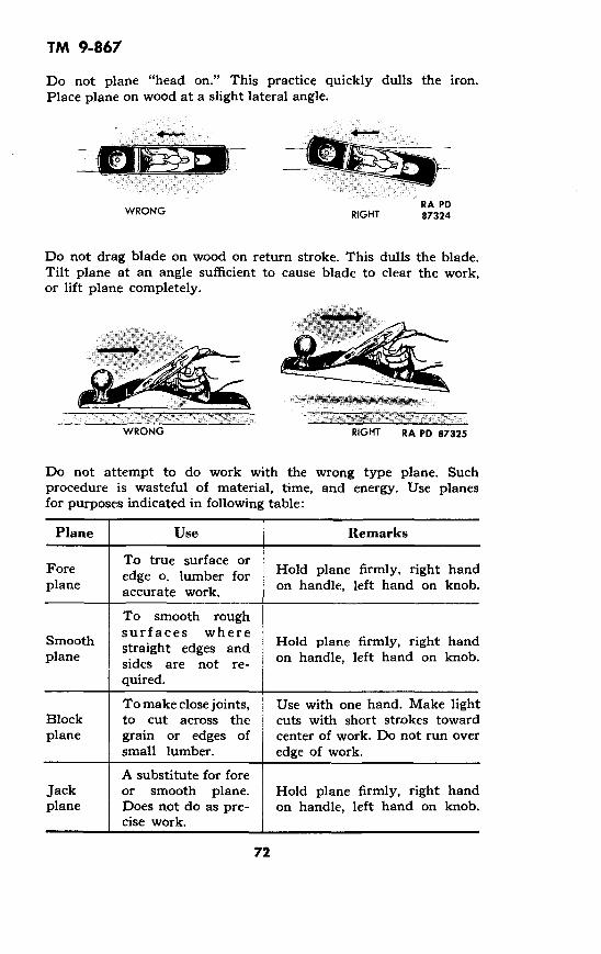
Do not plane "head on." This practice quickly dulls the iron.Place plane on wood at a slight lateral angle.
WRONG RIGHTRA PD87324
Do not drag blade on wood on return stroke. This dulls the blade.Tilt plane at an angle sufficient to cause blade to clear the work,or lift plane completely.
I
WRONG RIGHT RA PD 87325
Do not attempt to do work with the wrong type plane. Suchprocedure is wasteful of material, time, and energy. Use planesfor purposes indicated in following table:
Plane Use Remarks
To true surface orFore edge o lumber for Hold plane firmly, right handplane accurate work, on handle, left hand on knob.
To smooth roughsurfaces where
Smooth straight edges and Hold plane firmly, right handplane sides are not re- on handle, left hand on knob.
quired.
To make close joints, Use with one hand. Make lightBlock to cut across the cuts with short strokes towardplane grain or edges of center of work. Do not run over
small lumber. edge of work.
A substitute for foreJack or smooth plane. Hold plane firmly, right handplane Does not do as pre- on handle, left hand on knob.
cise work.
72
- '
TM 9-867
LubricationKeep irons and screw threads coated with a thin film of preserva-tive lubricating oil (special).
StoragePlane irons should always be withdrawn fully into the plane bedwhen tool is stored. Before storing, coat all metal parts of planeswith rust preventive compound (thin film). Store planes in boxesor in racks in a manner to protect cutting edges of irons fromcontact with wood, metals, or abrasives. Store in a dry place. Uponremoval from storage, wash metal parts with dry cleaning solventto remove rust preventive compound.
73

TM 9-867
Section XX
PUNCHES
TAPER PUNCH
HOLLOW PUNCH PRICK PUNCH
CENTER PUNCH
PIN PUNCH 9RA PD 87326
GRINDING AND SHAPING
Blunt End PunchesGrind pin punch, taper punch, or other blunt end punch so endis perfectly flat and at right angles to centerline of punch.
RIGHT WRONG WRONG WRONGEND IS FLAT END IS FLAT END IS END IS
AND AT BUT NOT AT ROUNDED HOLLOWEDRIGHT ANGLE RIGHT ANGLE OR BULGED OUT OR -
TO PUNCH TO PUNCH CURVEDAXIS AXIS INWARD
1. Set rest horizontal and at centerof grinding wheel.2. Start wheel and feed punch intogrinding surface of wheel at rightangles to surface.3. Twist punch during grinding toget flat end on punch.4. Cool punch frequently in water )to preserve temper. RA PD 873275. Do not grind away more metalthan necessary to get a satisfactoryend.
74

TM 9-867
Cone-pointed PunchesCenter punches and prick punches are ground to cone points.Correct point angle for center punches is about 90 degrees. Rightpoint angle for prick punch is approximately 30 degrees. Theseangles may be altered for special work.
.... \ ~300
CENTER PUNCH 900 PRICK PUNCH
RA PD 87328 RA PD 87329
Correct Punch Point AnglesAdjust rest so punch meets faceof wheel at desired angle (seeillustration). Rotate punch duringgrinding to make point symmetri-cal. Dip punch in water at fre-quent intervals to avoid "burning."Do not grind away more materialthan necessary to secure satisfac- RA PD 87330tory point.
Repairing Mush-roomed HeadGrind to original shape. Alwaystemper punch after repairingmushroomed head or it will quick- RA PD 87331ly mushroom again.
TemperingPunches must be hardened and tempered if point has been groundback past hardened section, if punch has been heated, or if mush-roomed head has been removed. Procedure for hardening andtempering is exactly like that described for machinist's chisels(section 8).
Common Misusesto AvoidNever use a punch whichhas a mushroomed head. XThere is danger of in-jury from flying pieces.Grind head to original
RA PD shape and temper punch RIGHTWRONG 87332 before using. RA PD 87333
75

Do not use a cone-pointedpunch to drive out a pin. Thepunch may spread the pin andruin the work. Use a pin punchor taper punch to do this work.
StorageCoat punches with rust pre-ventive compound (thin film),and store in a dry place. Uponremoval from storage, washwith dry cleaning solvent toremove compound.
76
TM 9-867
WRONG
RA PD 87334
RIGHT
RA PD 87335

TM 9-867
Section XXI
REAMERS
HAND
POWER REAMER
EXPANSION REAMER
ADJUSTABLE REAMER RA PD 87336
MAINTENANCEReamers, being precision cutting tools used for accurate sizing ofholes, must be used, handled, and stored with every precaution toprevent denting, marring, or damage to the cutting edges.
Reamers must not be thrown into a tool box or allowed to liearound unprotected on the bench.
Wrap reamers in slightly oiled cloths, using preservative lubricat-ing oil (special), when they are not in use on the bench or in toolcrib storage.
Partitioned boxes or drawers make excellent tool crib storage.Each reamer must have its own storage space.
77

TM 9-867
Adjustable Reamer CareAdjustable reamers should not be adjusted beyond the maximumsize for which the reamer was made.
When using removable blade reamers, make sure the adjustmenthas been properly made. The blades must be properly tightenedbetween the adjusting nuts. Any looseness may cause breakageduring use.
Misuses of ReamersTurning a reamer backward to remove it from the work.
This results in dulling cutting edges, necessitating grinding toresharpen. Grinding reamers makes them cut undersize. Alwaysturn forward (clockwise) with a reamer, using the same rotation forremoving as for cutting.
Turning a hand reamer with machine power.This practice often breaks reamers, due to use of too much power,
jamming or fitting, and clogging. Avoid using hand reamers withpower.
CleaningBlow clean with air, wipe with a clean rag, and wrap in a ragslightly dampened with oil.
StorageCoat reamers with rust preventive compound (thin film) and storein a dry place. Store in racks or divided boxes to protect cuttingedges from contact with metal. Upon removing from storage, washwith dry cleaning solvent to remove rust preventive compound.
78

TM 9-867
Section XXII
SAWS
c ~KEYHOLE..5L -a
COMPASS
NAIL SAW
RA PD 87337
CLEANING AND OILING(All Types of Saws)
Saws should be kept dry at all times. When necessary to use sawunder unfavorable weather conditions, wipe moisture from bladeafter using. Always oil blade with a clean cloth dampened withpreservative lubricating oil (special) after using saw. Do not permitblade to rust. Clean off all signs of rust from blade with crocuscloth. Apply oil to blade after cleaning off rust.
SHARPENING WOOD-CUTTING SAWSGeneralThere are two general types of teeth used on wood-cutting handsaws. Saws having one type of teeth are called rip saws and areused for cutting with the grain of wood. Saws having the othertype of teeth are called crosscut saws. They are used to cut acrossthe grain of wood. Before attempting to sharpen saws, a clearpicture of the shape of these teeth is necessary.
835846 0 - 49- 6 79
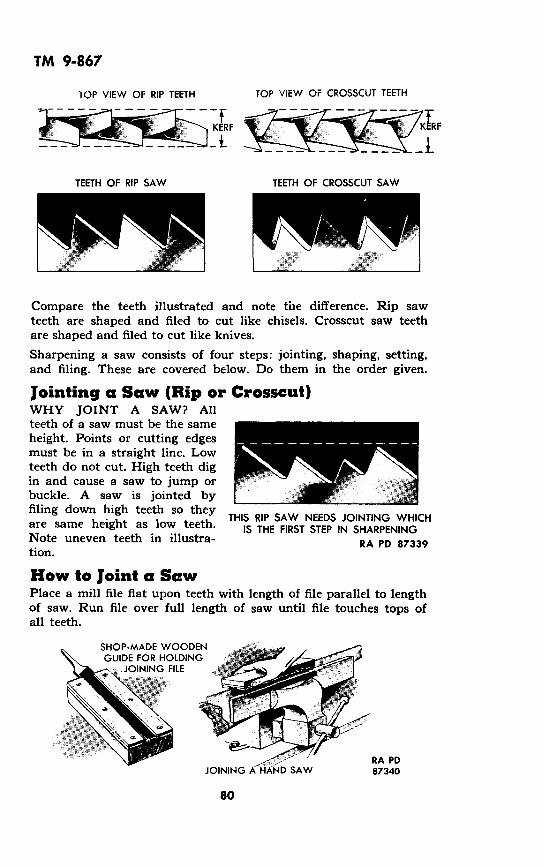
TOP VIEW OF RIP TEETH
TEETH OF RIP SAW
TOP VIEW OF CROSSCUT TEETH
TEETH OF CROSSCUT SAW
Compare the teeth illustrated and note the difference. Rip sawteeth are shaped and filed to cut like chisels. Crosscut saw teethare shaped and filed to cut like knives.
Sharpening a saw consists of four steps: jointing, shaping, setting,and filing. These are covered below. Do them in the order given.
Jointing a Saw (Rip or Crosscut)WHY JOINT A SAW? Allteeth of a saw must be the sameheight. Points or cutting edgesmust be in a straight line. Lowteeth do not cut. High teeth digin and cause a saw to jump orbuckle. A saw is jointed by
filing down high teeth so they THIS RIP SAW NEEDS JOINTING WHICHare same height as low teeth. IS THE FIRST STEP IN SHARPENINGNote uneven teeth in illustra- RA PD 87339tion.
How to Joint a SawPlace a mill file flat upon teeth with length of file parallel to lengthof saw. Run file over full length of saw until file touches tops ofall teeth.
SHOP-MADE WOODENGUIDE FOR HOLDING
JOINING FILE
RA PDJOINING A HAND SAW 87340
80
TM 9-867
_F-KERF R
- t - I
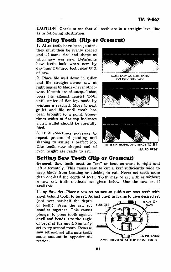
TM 9-867
CAUTION: Check to see that all teeth are in a straight level lineas in following illustration.
Shaping Teeth (Rip or Crosscut)1. After teeth have been jointed,they must then be evenly spacedand of same size and shape aswhen saw was new. Determinehow teeth look when new byexamining unused teeth near buttof saw.
SAME SAW AS ILLUSTRATED2. Place file well down in gullet ON PREVIOUS PAGEand file straight across saw atright angles to blade-never other-wise. If teeth are of unequal size,press file against largest toothuntil center of flat top made byjointing is reached. Move to nextgullet and file until tooth hasbeen brought to a point. Some'times width of flat top indicatesa new gullet should be carefullyfiled.
3. It is sometimes necessary torepeat process of jointing andshaping to assure a perfect job
RIP TEETH SHAPED AND READY TO SETThe teeth now shaped and of
RA PD 87341even height are ready to set.
Setting Saw Teeth (Rip or Crosscut)General. Saw teeth must be "set" or bent outward to right andleft alternately. This causes saw to cut a kerf sufficiently wide tokeep blade from bending or sticking in cut. Never set teeth morethan one-half the depth of teeth. Teeth may be set with or withouta saw set. Both methods are given below. Use the saw set ifavailable.
Using Saw Set. Place a saw set on saw so guides are over teeth withanvil behind tooth to be set. Adjust anvil in frame to give desired set(not over one-half the depth 1 BLADE OFof teeth). Press the saw set FLUNGER-- SAWhandles together. This causesplunger to press tooth againstanvil and bends it to the angleof bevel of the anvil. Similarlyset every second tooth. Reversesaw set and set alternate teethsame amount in opposite di- RA PD 87342rection. ANVIl (BEVELED AT TOP FRONT EDGE)
81

TM 9-867
Without Saw Set. Prepare a steel BEVEL
or hardwood block similar tosketch. Dimensions shown areminimum; block may be larger.Angle of the bevel must be deter-mined by examination of the saw 3
to be set; however, angle A must RA PD 87343
be not less than 146 degrees orsaw teeth will break off when set.
Place saw on block as shown insketch. Clamp saw and blocktogether. Place a blunt end punch PUNCH
on tooth to be set. Strike punchsmartly with a hammer to settooth. Similarly set every second SAW BLADE
tooth which is over block. Moveblock along to set remaining BLO
teeth. Apply block to other side BLOCKof saw to set alternate teeth. RA PD 87344
FILING THE RIP SAWNumber of teeth per inch determines point size of saw; for example,a saw having eight teeth per inch of blade is an 8-point saw. Forfiling 4y/2-, 5-, or 6-point saw, use a 7-inch slim taper file; for9- and 10-point saws, use a 5- or 5X2-inch slim taper file.
CLAhMrP HANDLE
4 FILEBLADE RA PD 87344A
FIRST POSITION FOR FILING RIPSAW
1. Joint saw lightly as an aid to filing.2. Place saw in filing clamp with handle at the right. Bottom oftooth gullets should be Y8 inch above jaws of clamp. If more ofblade projects, file will chatter or screech. This will dull filequickly. Start at point of rip saw indicated in above illustration.Pick out first tooth set toward you. Place file in gullet to left ofthis tooth. Hold file level and at angle indicated (right angle). Fileshould set well down in gullet. Study unworn teeth near handle-factory shaped teeth are an excellent guide.
82

TM 9-867-'FILE
o'er~~~1 N\
POSITION OF FILE BETWEEN TEETH AMOUNT OF TOOTH FILED AWAY INFIRST POSITION
RA PD 87345
File should cut on push stroke. It files back of tooth to left andfront of tooth to right at same time. File teeth until one-half of flattops, made as a guide, are cut away. Lift file from gullet and skipnext gullet to right. Place file in second gullet toward handle.Repeat filing operation at same angle as before, and continueskipping one gullet until you reach handle end of saw.3. Turn saw blade around in clamp, placing handle of saw to left.Take position indicated in following figure.
HANDLE
I
SECOND POSITION FOR FILING RIPSAW
Place file in gullet to right of firstthe first of gullets you skippedwhen filing other side of saw. Atcorrect angle (right angle), fileuntil you cut away other half offlat top and teeth are shaped topoints. Continue this operationin every second gullet until youreach saw handle. All teethshould be same height and shape.
tooth set toward you. This is
AMOUNT OF TOOTH FILED AWAYIN SECOND POSITION
RA FD 87347
FILING CROSSCUT SAWCrosscut saw filing is exactly the same as rip saw filing with onehighly important exception-the angle at which file is held. A cross-cut saw is filed so teeth have a 45-degree bevel. Handle end of fileis held about 15 degrees below the horizontal. Study followingillustrations.
83

TM 9-867
450FS CLAMP
FIRSTPOSITION x =- T.-. n.... = ._..A..]
LFILE BLADE
/,IE
HANDLE FILE
450
_/
i "/.~ m. SECONDHANDLE BLADE C MPOSITION
HANDLE BLADE CLAMP \
FILE
FILING CROSSCUT SAW
RA PD 87348
After one side of saw is filed, turn it around and file other side.Never file all teeth from same side, as this causes saw to run to oneside.
NOTE: Variations in bevel in crosscut saw for work on medium orhard woods are desirable, but only experience will indicate whatis best.
Additional Filing Hints1. Tighten clamp securely to reduce vibration.
2. Use file recommended for work.
3. Adjust stroke so file is eased into gullet.
4. File at rate of about 60 strokes per minute-no more.
5. Use long, steady, uniform stroke.
6. Raise file on return stroke.
7. Exert enough pressure on file to keep it cutting on forwardstroke. Do not slide file.
8. Shape teeth with a worn file. Sharpen with a new one.
84

TM 9-867
REPLACING HANDLES(Most Types of Saws)
Remove the special screws and nuts which attach handle to blade.Slide handle off blade. Position new handle on butt end of bladewith screw holes in handle and blade alined. Install the specialscrews and nuts which attach handle to blade.
Common Misuses (Wood-cutting Saws)Do not lay saws on floor or place loose in a tool box. Such treat-ment may lead to dulled or bent teeth or sprung blades. Hang sawsup when not in use.
WRONGRIGHT
¶RA PD 87349
Never saw into nails with a wood-cutting saw. This will dull, bend,or break teeth. Remove nails from repair or alteration work beforesawing.
WRONG RIGHT
RA PD 87350
Do not twist off strips of waste with blade. This dulls and bendsteeth and may spring blade. Break off strips of waste with handor mallet.
i RA PDWRONG RIGHT 87351
85
4·

TM 9-867
Do not allow waste side of work to break off as cut is made. Thispractice causes work to split. Support waste side and cut clearthrough work.
WRONG RIGHTRA PD 87352
Do not allow end of saw to strike floor. There is danger of springingthe blade. Raise work high enough to get clearance. If work cannotbe raised, limit the stroke.
:000: 4 '/j\N // t\:
RA PD 87353
Care and Adjustment of HacksawsSelect blade with proper number of teeth per inch to handle job athand. Following table shows blades to use for various jobs to bedone with hand hacksaws.
Material Teeth Per InchAluminum .............................. 14Brass--cast (soft) ....................... 18Brass--cast (hard) ...................... 18Brass tubing ............................ 24Cast iron ............................... 18Copper ................................. 14Cold-rolled steel ........................ 18High-speed steel ........................ 18Iron pipe conduit ........................ 24Steel tubing ............................ 24Structural steel ......................... 18Tool steel .............................. 18
Install blade in frame to cut on forward stroke. When in use, maketension of blade great enough so it cannot buckle under pressure
86

TM 9-867
of the stroke. On the other hand, do not strain blade so much thatslight canting of the frame will break it.
Relieve blade tension when saw is not in use.
Common Misuses (Hacksaws)Do not attempt to do job with wrong type blade. It makes workhard to do and results in blade spoilage. Use blade recommendedin table under "Care and Adjustment of Hacksaws," on page 86.
TEETH TOO SMALL- TEETH COARSE TEETH- TWO OR MORENO CHIP TOO COARSE- AMPLE CHIP TEETH ON
CLEARANCE- STRADDLES CLEARANCE METALTEETH CLOG WORK RA PD
WRONG RIGHT 87354
Do not attempt to cut insecurely fastened work. Blade breakageoften results. Anchor work securely.
RIGHT
iRON RA PD 87355
Do not use a new blade in a cut started with another blade. Thenew blade is likely to wedge and break. Turn work over and startnew cut from opposite side.
WRONG RIGHT
-I..
RA PD 37356
87

TM 9-867
WRONGRA PD 87357
Never start cuts on sharpangles. This practice is likelyto strip saw teeth. Start thecut with blade held at a slightangle to the surface.
RIGHTRA PD 87358
Do not install blade so teeth point toward handle. Blade will notcut properly. Point teeth away from handle, tighten securely, andretighten after first few strokes.
RA PDRIGHT 87359WRONG
Do not apply too great or insufficient pressure to blade. Eitherabuse ruins blades. Apply just enough pressure on face stroke tomake teeth "bite."
TOO GREAT PRESSURE- CORRECT PRESSURE-BLADEBLADE BREAKS CUTS ON FORE STROKE
RA PD 87360
StorageApply rust preventive compound (thin film) to blades to preventrust, and store so teeth will not be dulled by contact with othertools. Upon removal from storage, wash metal parts with drycleaning.solvent to remove compound.
88
"C -- 'I'll, �

TM 9-867
Section XXIII
SCRAPERS
SINGLE HANDLEBOX SCRAPER
FLAT SCRAPER
THREE CORNEREDBEARING SCRAPER
BEARING SCRAPER
CARE AND CLEANINGProtect cutting edges of bearingcloth case when not in use.
scrapers by enclosing blade in a
Keep scrapers clean at all times. Wash them in dry cleaningsolvent and wipe them with a clean cloth.
SHARPENING
CROSS SECTIONS OFBEARING SCRAPERS
RA PD 87362
Bearing ScrapersSelect an oilstone "slip" of exactlythe right size to fit interior bevelof hollow-ground scraper. Holdscraper firmly on a bench and rubslip back and forth full length ofbevel a few times.
Flat ScrapersFlat scrapers are sharpened with a file or on an oilstone, forming abevel on one side only.
89
CARBONSCRAPER
RA PD 87361

TM 9-867
BOX SCRAPERS
GeneralTwo types of edges are usedon box scrapers, squareturned edge and bevel turnededge. For fine work, usesquare turned edge; for fastwork, use bevel turned edge.
Square TurnedEdgeAdjust guide of a fine abra-sive wheel to right angleswith face of wheel. Grind tipof scraper blade, as illus-trated, until perfectly square.
Clamp blade in vise andsmooth off edge with a finemill file. Use care to keepedge flat and at right anglesto sides of blade.
Use a burnishing tool or asmooth piece of steel such asthe heel of a file or the sideof a chisel blade to rub thescraping edge of tool as illus-trated. Use considerable pres-sure. Stop burnishing as soonas the edges are turned asillustrated.
RIGHT _ R
SQUARE TURNEDEDGE
IGHT
BEVEL TURNEDEDGE
_4.-
U.Bevel Turned Edge RA PD 87368
Adjust rest of an abrasive wheel to get a bevel of about 45 degrees.Grind scraper as illustrated until indicated bend is obtained. Dipfrequently in water to prevent burning. Do not grind away moremetal than necessary to obtain a nick-free and straight bevel.
SIDE VIEW TOP VIEW CORRECT BEVELRA PD87364
90
I I I I

TM 9-867
Place bevel flat on a fine oilstone.Swaying the entire body from the %feet, rub blade (in a figure eight <
motion) over surface of stone.Brush feather edge from scraperby rubbing flat side of bladelightly over stone.
Clamp blade in vise as illus-trated. With a burnishing tool,or other piece of flat smooth steel, .rub edge with sufficient pressureto turn it as shown in sketch.
Common MisusesDo not use scrapers as chisels,screwdrivers, knives, awls, orpunches. Such use will dull the RA PD 87365
scraper, and may bendor break it. Use tools
which they are intended.
Never toss scrapers intoboxes or onto other tools -
when not in use. Theiredges will be dulled. Keep
(0 scrapers in racks or di-RA PD vided boxes when not in
WRONG 87366 RA PD 87367use.
WRONG R IRA PD 87368
StorageCoat scrapers with rust preventive compound (thin film) at timeof storing, and store in a dry place. Upon removal from storage,wash metal parts with dry cleaning solvent to remove rust preven-tive compound.
91

TM 9-867
Section XXIV
SCREWDRIVERS
CROSS RECESS (PHILLIPSI
RA PD 87369
CARE AND CLEANINGWash grease and grime from screwdrivers with dry cleaning solvent.Scour rust from blade with crocus cloth or aluminum oxide abrasivecloth. Keep blade coated with a film of preservative lubricating oil(special) or engine oil (SAE 10). Lubricate spirals and frictionsurfaces of spiral ratchet screwdrivers with preservative lubricatingoil (special) or engine oil (SAE 10).
GRINDINGStandard Type ScrewdriverScrewdriver tips should be ground with sides parallel to keep toolfrom lifting from screw slot when in use.
CAUTION: Dip screwdriver in water frequently during grinding toprevent loss of temper by overheating.
RIGHT RIGHT WRONG
SIDES OF TIP SIDES OF TIP SIDES ARE GROUNDARE PARALLEL. ARE SLIGHTLY AT AN ANGLE IN
TOOL WILL NOT U HOLLOWED OR AN ATTEMPT TOLIFT WHEN TWIST SHAPE OF MAKE TOOL WORK
IS APPLIED GRINDING WHEEL IN ANY. SIZE SCREW.
RA PD 87370
92

TM 9-867
1. Adjust rest to hold screwdriver at right angles to grindingsurface of wheel. Grind end square. Do not grind away morematerial than necessary to remove nicks and "square up" end.
1. REMOVE NICKS 2. GRIND SIDES
RA PD 87371
2. Adjust rest to hold screwdriver against wheel to give desiredparallel or concave shape. Grind both sides until tip is of requiredthickness.
Cross Recess and Clutch Head ScrewdriversTools of this type require special holding fixtures to grind. In anemergency, these tools can be shaped by grinding or filing. Usecare to maintain original angles and bevels.
TemperingIf hardened tip has been broken off or ground away, or if tool hasbeen heated, screwdriver must be hardened and tempered.
Heat about one and one-half inches of tip of blade to cherryred with a gasoline torch, gas furnace, or charcoal fire. Dip about3/4 inch of tip in clean, cold water. Quickly rub hardened end withaluminum oxide abrasive cloth or oilstone to brighten it. Watchcolor creep back into tip from heated portion of blade. Quenchwhen light blue color reaches tip.
Polish blade withemery cloth andcrocus cloth in
,' aturn. Grind bladeto proper shape.
CommonMisuses toAvoid PBARDo not use ascrewdriver as apry bar. It will RIGHT
WRONG bend or break. UseRA PD 87372 pry bar for prying. RA PD 87373
93
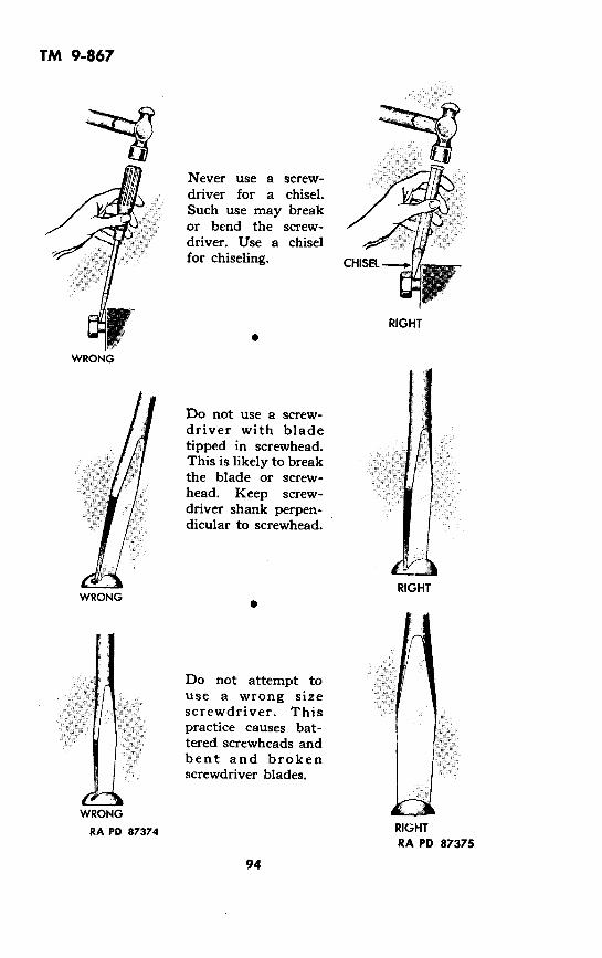
TM 9-867
63,
Never use a screw-driver for a chisel.Such use may breakor bend the screw-driver. Use a chiselfor chiseling.
RIGHT.
Do not use a screw-driver with bladetipped in screwhead.This is likely to breakthe blade or screw-head. Keep screw-driver shank perpen-dicular to screwhead.
Do not attempt touse a wrong sizescrewdriver. Thispractice causes bat-tered screwheads andbent and brokenscrewdriver blades.
RIGHT
RA PD 87375
94
WRONG
WRONG
/
WRONG
RA PD 87374

TM 9-867
Never use pliers or wrench on screwdriver blade. Blade is likely tobend or point break off. Apply only what pressure can be put onhandle by hand.
RA PDWRONG RIGHT 87376
StorageSpread rust preventive compound (thin film) over metal parts ofscrewdrivers, and store in a dry place. Upon removal from storage,wash metal parts with dry cleaning solvent to remove rust pre-ventive compound.
835846 0 - 49 - 7 95

TM 9-867
Section XXV
SHEARS
STRAIGHTBLADE
TINNER'SSHEARS
RA PDCURVED BLADE TINNER'S SHEARS 87377
CARE AND CLEANINGWash grease or other dirt from shears with dry cleaning solvent anddry with a soft cloth. Lubricate pivot screw or bolt with a dropof preservative lubricating oil (special) or engine oil (SAE 10).Scour rust from shears with fine aluminum oxide abrasive cloth.Apply a light film of oil to shears with a cloth to prevent rust.Keep pivot screw or bolt tight enough to prevent side play but nottight enough to cause binding.
96

TM 9-867
GRINDINGShears must be ground if cutting edge is nicked or if bevel is dis-torted from improper sharpening. Dull shears can usually besharpened on an oilstone without grinding. Never grind shears ifsharpening will suffice; most shears are useless after two or threeregrindings. A single bevel is used. It may be flat or concave. Itmust not be convex. Study the following cross-section views ofcorrect and incorrect bevels.
IRIGHT
BEVEL ISPERFECTLYFLAT ORSTRAIGHTACROSS
L RIGHT
BEVEL ISSLIGHTLY
CONCAVE ORSHAPE OF
GRINDING WHEEL
I
WRONG
BEVEL ISROUNDED OUT
FROM INCORRECTGRINDING ORSHARPENING
WRONG
BEVEL ISON WRONG
SIDE.SHEARS WILL
NOT CUT
Bevel angles vary with type ofwork for which shears are used.Bevel usually makes an angle offrom 60 to 85 degrees with flatinside surface of blade. Paper-cutting and cloth-cutting shearsare usually ground to a 60-degreebevel; tin-cutting shears are usu-ally ground to a bevel of approxi-mately 85 degrees. Bevel angle canusually be determined by examin-ing an undamaged portion ofblade. If bevel has been distortedits entire length, examine an un-damaged pair of similar typeshears to ascertain what correctbevel should be.
II I WRONG
DOUBLE BEVEL iIS USED.
SHEARS WILLNOT CUT |
BEVEL ANGLE
ANGLE "A" VARIES FROM 600 TO85° DEPENDING ON USE FOR
WHICH SHEARS ARE DESIGNEDRA PD 87378
97
General

TM 9-867
ProcedureCAUTION: Use a fine grain wheel, properly dressed. Dip shearsinto water frequently during grinding to prevent loss of temper.
1. Adjust rest to position which will give correct bevel.
2. Start wheel and place shears blade on rest, bevel side down.Move blade into contact with wheel. Move shears blade continuallyfrom side to side during grinding. Keep motion uniform to ensurestraight cutting edge.
3. Turn shears over on rest and grind other blade.
RA PD 87379
SharpeningApply blade to lightly oiled oilstone so flat surface lies flat onstone with blade crossing stone at right angles. Draw blade smartlyacross stone from heel to point, so as to remove wire edge. Starteach stroke at heel of blade. Stone other blade in same manner.
1 [
RA PD 87380
Common MisusesNever use shears as screwdrivers, hammers, or pry bars. Theybreak easily. Use any tool only for the purpose for which it wasdesigned.
98

TM 9-867
RIGHT
SCREWDRIVER -_
RA PD 87381
Do not attempt to cut heavier materials than shears are meant tohandle. It will dull and possibly break the blades. Use shears de-signed to do the job.
WIRECUTTERS
RIGHT RA PD87382
Never toss shears into a tool boxlikely to be broken. Hang themuncrowded shelf when not in use.
WRONG
They will become dull and areon hooks or lay them on an
RA PDRIGHT 87383
StorageApply rust preventive compound (thin film) to shears at time ofstoring. Store in a dry place with cutting edges protected fromcontact with other objects. Wash off rust preventive compoundwith dry cleaning solvent upon removal from storage.
99
WRONG

TM 9-867
Section XXVI
SOLDERING IRONS
SOLDERING COPPER
ELECTRICSOLDERING IRON
RA PD 87384
PREPARING FOR USE
Soldering CopperThis involves cleaning, heating, hammering, annealing, filing point,and tinning. Some of these steps are not required every time acopper is conditioned. To perform satisfactorily, a copper musthave a well-formed, well-cleaned, and well-tinned point.
1. File all old solder and scale from point end. This is important.If neglected, solder and scale will prevent proper tinning of point.
RA PD 87385
100

TM 9-867
2. Heat copper to a dull red. Do not direct heat at point becauseof danger of burning it. Use gas flame, blowtorch, or charcoal fire.3. File point to proper shape. Point should taper back to efficientworking angle, depending on size of copper. Point should be slightlyrounded.4. Plunge red-hot copper into cold water. This anneals copper,making it softer for filing, easier to tin, and more efficient atgiving off heat.5. File all rough spots from point end of copper, finishing with afine file to a flat, smooth surface. This polishing makes tinninglast longer.
6. Heat copper so it will just melt solder. Wipe copper on wetrag to clean surfaces. Place a few drops of solder on block ofammonium chloride (sal ammoniac). Rub copper on ammoniumchloride and in melted solder until copper acquires a bright tinnedsurface.
AMMONIUM CHLORIDE POOL F SOLDER
TIN POINT RA PD 87386
7. Clean tinned point each time it is removed from heater. Whenpits form on copper back of tinned area, heat copper and dip inwater to remove scale.
Electric Soldering IronShape and clean point by filing. Tin point in manner similar toprocedure for tinning soldering copper. However, do not use ex-ternal source of heat and do not dip iron in water.
REPAIR(Electric Soldering Iron)
1. If iron does not heat with plug installed in a "live" receptacle,an open circuit is indicated in plug, cord, or element. Visuallyinspect the parts to see if there is a bent plug prong or "pulled"connection. Feel along length of wire for breaks inside insulation.If open circuit cannot be found by visual inspection, disconnectcord from iron. Test cord and element separately with test lamp.Replace faulty part.
101

TM 9-867
2. If fuse "blows" when iron is plugged into receptacle, a shortcircuit is indicated in plug, cord, or element. Inspect plug and cord,looking for damaged insulation. If unable to locate short, test cordand element separately, with test lamp. Replace short-circuitedparts.
Common MisusesDo not leave electric soldering iron connected for long periods onthe chance it may be wanted. This practice is hard on elementsand wasteful of current. Disconnect electric soldering iron whennot in use.
WRONG RIGHT RA PD 87387
Do not throw coppers into tool box. Therethe point. Hang coppers up or place on annot in use.
WRONG
is danger of batteringuncrowned shelf when
'! -i i _: ii
! ! i 'i ii
RIGHT
. SE
- t \;
23_i
I: I0 ini _
RA PID87389
StorageCoat iron shaft and ferrule with rust preventive compound (thinfile), and store in a dry place.
102
QAI
00
INI I -!
!-,, 1

TM 9-867
Section XXVII
TAPS AND DIES
TAPER TAP
PLUG TAP
ROUND SPLIT DIE
BOTTOMING TAP
DIE STOCK
PIPE DIEHEAD AND
RATCHETSTOCK
PIPE DIE
! '--TAP WRENCHES
RA PD 87389
103
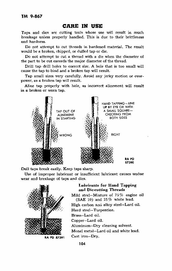
TM 9-867
CARE IN USETaps and dies are cutting tools whose use will result in muchbreakage unless properly handled. This is due to their brittlenessand hardness.
Do not attempt to cut threads in hardened material. The resultwould be a broken, chipped, or dulled tap or die.
Do not attempt to cut a thread with a die when the diameter ofthe part to be cut exceeds the major diameter of the thread.
Drill tap drill holes to correct size. A hole that is too small willcause the tap to bind and a broken tap will result.
Tap small sizes very carefully. Avoid any jerky motion or over-power, as a broken tap will result.
Aline tap properly with hole, as incorrect alinement will resultin a broken or worn tap.
HAND TAPPING-LINEUP BY EYE OR WITH
TAP OUT OF A SMALL SQUARE-h | l lALINEMENT M~i i CHECKING FROMIN STARTING BOTH SIDES
WRONG "* ~~~~ RIGHT
RA PD87390
Dull taps break easily. Keep taps sharp.
Use of improper lubricant or insufficient lubricant causes unduewear and breakage of taps and dies.
Lubricants for Hand Tappingand Die-cutting Threads
Mild steel-Mixture of 75 % engine oil(SAE 10) and 25% white lead.
High carbon and alloy steel-Lard oil.
Hard steel-Turpentine.Brass-Lard oil.
Copper-Lard oil.Aluminum-Dry cleaning solvent.Monel metal-Lard oil and white lead.
RA PD 87391 Cast iron-Dry.
104

TM 9-867
For tapping blind holes, tap drill sufficiently deep so there isamDle room for chips, or a broken tap will result.
CHIPS BIND TAP-DRILL HOLE DEEPERTO PREVENT BINDING ANDRESULTANT TAP BREAKING
HOLE HAS SUFFICIENT DEPTH TOKEEP CHIPS FROM BINDING
RA PD 87392
Remove all chips from a blind hole before using final bottomingtap. This prevents breakage of bottoming tap.
Select proper size tap wrench. A large wrench on a small tapmay cause undue strain and breakage will result.
Taps must be kept in a box, as illustrated, when not in use.
WRONG
RIGHT-HAVE AN ARRANGEMENTSO TAPS AND DIES WILL NOT SIRIKEEACH OTHER OR ANY OTHER TOOLS
RA PD 87393
Sharpening TapsDull leading or chamfered threads cause much tap breakage. Keeptaps sharp by proper grinding.
RIGHT
RA PD 87394
105
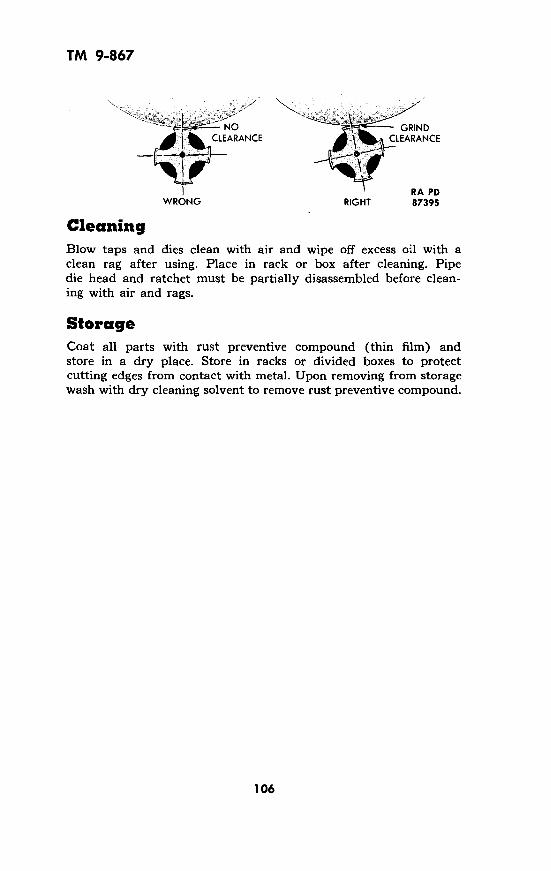
TM 9-867
~~NO GRINDCLEARANCE e CLEARANCE
RA PDWRONG RIGHT 87395
CleaningBlow taps and dies clean with air and wipe off excess oil with aclean rag after using. Place in rack or box after cleaning. Pipedie head and ratchet must be partially disassembled before clean-ing with air and rags.
StorageCoat all parts with rust preventive compound (thin film) andstore in a dry place. Store in racks or divided boxes to protectcutting edges from contact with metal. Upon removing from storagewash with dry cleaning solvent to remove rust preventive compound.
106

TM 9-867
Section XXVIII
VISES
MACHINIST'S VISE
BLACKSMITH'SVISE
PIPE VISE UTILITY VISE RA PD 87396
CleaningWash grease and dirt from vise with dry cleaning solvent. Wipedry with a cloth. Clean jaws with a wire brush. Pick chips frombetween serrations with a file scorer or a flattened iron wire.
LubricationLubricate slide and worm lightly with preservative lubricating oil(special) or engine oil (SAE 10). Lubricate sparingly; excessiveamounts help cause a messy shop.
Common MisusesDo not use vise jaws as a heavy anvil. There is danger of breakingjaws or battering inserts. Use an anvil for anvil jobs.
7
WRONGLRIGHT
RA PD 87397
107
7;0-�
t\~ '.
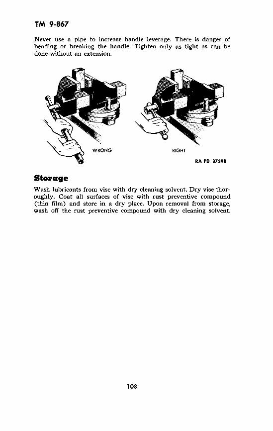
TM 9-867
Never use a pipe to increase handle leverage. There is danger ofbending or breaking the handle. Tighten only as tight as can bedone without an extension.
WRONG RIGHT
RA PD 87398
StorageWash lubricants from vise with dry cleaning solvent. Dry vise thor-oughly. Coat all surfaces of vise with rust preventive compound(thin film) and store in a dry place. Upon removal from storage,wash off the rust preventive compound with dry cleaning solvent.
108
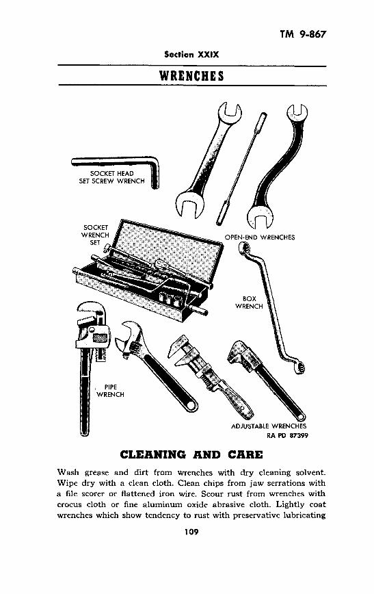
TM 9-867
Section XXIX
WRENCHES
SOCKET HEADSET SCREW WRENCH
ADJUSTABLE WRENCHES
RA PD 87399
CLEANING AND CAREWash grease and dirt from wrenches with dry cleaning solvent.Wipe dry with a clean cloth. Clean chips from jaw serrations witha file scorer or flattened iron wire. Scour rust from wrenches withcrocus cloth or fine aluminum oxide abrasive cloth. Lightly coatwrenches which show tendency to rust with preservative lubricating
109

TM 9-867
oil (special) or engine oil (SAE 10). Lubricate slide and worm ofadjustable wrenches with a drop or two of the oil.
MAINTENANCEGrinding and FilingOpen-end and adjustable wrenches with battered, nicked, or spreadjaws can sometimes be made serviceable by grinding snd/or filing.When attempting this repair, enlarge open-end wrenches to nextstandard size. Make jaw faces perfectly flat and parallel. Dip wrenchin water frequently when grinding to preserve temper.
Removing Play from Adjustable Wrench1. Remove screw which acts as worm axle from wrench. Lift wormand worm spring from wrench.
2. Stretch worm spring. Insert spring into cupped end of wormand reassemble wrench. Tighten worm axle screw securely.
3. Prick punch wrench adjacent to screw to lock screw in position.
DISASSEMBLE WRENCH STRETCH WORM SPRING LOCK SCREWRA PD 874
Renewing Pipe Wrench Jaw SerrationsUsing a fine three-cornered or taper file,carefully deepen lowpoints between ser-rations. '
MisusesDo not push on awrench. It's danger-ous. Arrange work so
WRONG you can pull on RIGHTRA PD 87401 wrench. RA PD 87402
110
400
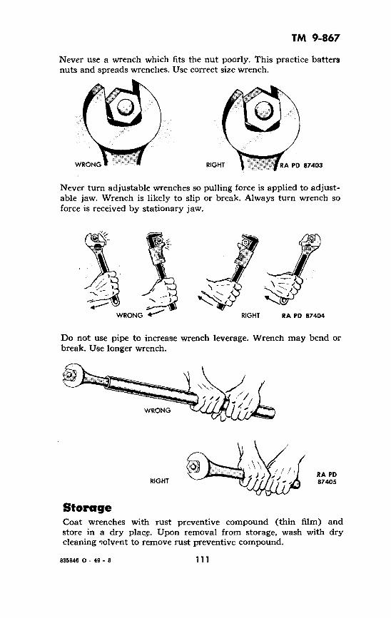
TM 9-867
Never use a wrench which fits the nut poorly. This practice battersnuts and spreads wrenches. Use correct size wrench.
WRONG RIGHT FRA PD 87403
Never turn adjustable wrenches so pulling force is applied to adjust-able jaw. Wrench is likely to slip or break. Always turn wrench soforce is received by stationary jaw.
WRONG I- RIGHT RA PD 87404
Do not use pipe to increase wrench leverage. Wrench may bend orbreak. Use longer wrench.
WRONG
RIGHTRA PD87405
StorageCoat wrenches with rust preventive compound (thin film) andstore in a dry place. Upon removal from storage, wash with drycleaning solvent to remove rust preventive compound.
111835846 0 - 49- 8

TM 9-867Section XXX
REFERENCES
PUBLICATIONS INDEXES.
The following publications indexes should be consulted frequentlyfor latest changes or revisions of references given in this section andfor new publications relating to materiel covered in this manual:
1. Ordnance supply catalog index (index toSNL's) ............................. ASF Cat.
ORD 2
2. Ordnance major items and combinations,and pertinent publications .......... SB 9-1
3. List of publications for training (listingCCBP's, FM's, FT's, MTP's, TB's,TM's, TR's, TC's and LO's) .......... FM 21-6
4. List of training films, film strips, and filmbulletins ............................ FM 21-7
5. Military training aids (listing graphictraining aids, models, devices, and dis-plays) .............................. FM 21-8
6. List and index of administrative and supplypublications (listing new AR's, Cir's,GO's, and WDP's, T/O & E's, T/O's,T/E's, T/S's, T/BA's, MR's, RR's,WDP's,SB's, MWO's, and Forms) .... WD Pam 12-6
STANDARD NOMENCLATURE LISTS.1. Common Tool Lists.
Abrasion and compression tools (generalabrasives, hand grinders, hand presses,sharpening stones, etc.) ................
Benches, tool boxes, cabinets, bins, toolchests, tool rolls, etc., of general application
Cutting, boring, and tweezer tools (saws,shears, planes, files, rasps, chisels, bits,reamers (hand), pliers, pincers, etc.).....
ASF Cat.ORD 5 SNL J-1
ASF Cat.ORD 5 SNL J-15
ASF Cat.ORD 5 SNL J-2
112

TM 9-867REFERENCES - Contd.
Geometrical tools and instruments (squares,compasses, rules, gages, calipers, microm-eters, dividers, levels, protractors, scribers,surface plates, etc.) .................... ASF Cat.
ORD 5 SNL J-3Hand tool appurtenances (file cleaners,
handles, heads, tool checks, tool racks,etc.) ................................. ASF Cat.
ORD 5 SNL J-8Lifting, holding, and forming tools (bit
braces, saw frames, vises, clamps, hoists,block and tackle, molds for castings,anvils, jacks and slings, etc.) ............ ASF Cat.
ORD 5 SNL J-5Measuring and testing instruments (elec-
trical, air, liquid, etc.) .................. ASF Cat.ORD 5 SNL J-9
Miscellaneous kits and tool-sets ........... ASF Cat.ORD 5 SNL J-20
Paint, spraying equipment and related items ASF Cat.ORD 5 SNL J-14
Percussion, digging, and wrecking tools (ham-mers, mallets, mauls, sledges, axes, hatchets,picks, mattocks, shovels, crowbars, pinchbars, etc.) ............................ ASF Cat.
ORD 5 SNL J-6Punch, drift, fastening, and scraping tools
(awls, needles, punches, drifts, screwdrivers,wrenches, scrapers, riveters (hand sets),etc.) ................................. ASF Cat.
ORD 5 SNL J-4Small tools (twist drills, countersinks,
counterbores, cutting-off tool cutters,cutters, etc.) .......................... ASF Cat.
ORD 5 SNL J-10Tire repair and maintenance tools and equip-
ment ................................. ASF Cat.ORD 5 SNL J-16
Welding, forging, soldering and brazingequipment (blow-torches, soldering coppers,melting ladles, and welding outfits) ....... ASF Cat.
ORD 5 SNL J-7
113

TM 9-867REFERENCES - Contd.
2. Maintenance Tool Lists.Tools, maintenance, for repair of pack, light
and medium field artillery; and armamentof these calibers for airplane and combatvehicles .............................. ASF Cat.
ORD 6 SNL C-18Tools, maintenance, for repair of small and
hand arms, and pyrotechnic projectors... ASF Cat.ORD 6 SNL B-20
Tool-sets for maintenance of antiaircraftartillery .............................. ASF Cat.
ORD 6 SNL D-14Section 2
Tool-sets for maintenance of antiaircraftmateriel (37-mm and 40-mm) ........... ASF Cat.
ORD 6 SNL A-35Section 2
Tool-sets (common), specialists' and organi-zational .............................. ASF Cat.
ORD 6 SNL G-27Section 2
Tool-sets for maintenance of heavy fieldartillery .............................. ASF Cat.
ORD 6 SNL D-14Section 1
Tool-sets for maintenance of sighting and firecontrol equipment ..................... ASF Cat.
ORD 6 SNL F-272
Tool-sets for maintenance of small and inter-mediate caliber ground, aircraft, andantiaircraft materiel; cannon and mortars. ASF Cat.
ORD 6 SNL A-35Section 1
Tool-sets (special), motor vehicles ......... ASF Cat.ORD 6 SNL G-27Section 1
3. Shop Loads Tool Lists. (truck and railway)
Car, railway, machine shop, M1 (for ord-nance company, maintenance-railwayartillery) ............................. ASF Cat.
ORD 7 SNL E-53
114

TM 9-867REFERENCES - Contd.
Truck, 214-ton, 6 x 6, small arms repair, M7,M7A1, and M7A2 ..................... ASF Cat.
ORD 7 SNL G-138Truck, 21/2-ton, 6 x 6, automotive repair, M8
and M8A1 ............................. ASF Cat.ORD 7 SNL G-139
Truck, 214-ton, 6 x 6, artillery repair, M9and M9A1 ............................ ASF Cat.
ORD 7 SNL G-140Truck, 212-ton, 6 x 6, instrument repair, M10
and M1OA1 ........................... ASF Cat.ORD 7 SNL G-141
Truck, 212-ton, 6 x 6, welding, M12 andM12A1 ............................... ASF Cat.
ORD 7 SNL G-142Truck, 214-ton, 6 x 6, tool and bench, M13. ASF Cat.
ORD 7 SNL G-143Truck, 21
2-ton, 6 x 6, machine shop, M16,M16A1 and M16A2 .................... ASF Cat.
ORD 7 SNL G-146Truck, 21/ 2-ton, 6 x 6, electrical repair, M18,
M18A1, and M18A2 ................... ASF Cat.ORD 7 SNL G-149
Truck, 214-ton, 6 x 6, instrument bench, M23 ASF Cat.ORD 7 SNL G-178
Truck, 214-ton, 6 x 6, Signal Corps generalrepair, M31; Truck, 212-ton, 6 x 6, smallarms repair (Signal Corps), M7 ......... ASF Cat.
ORD 7 SNL G-229Truck, tire repair, 212-ton, 6 x 6, M32
(Loads A and B) and Trailer, tire repair,1-ton, 2-wheel, M25 (Loads A and B).... ASF Cat.
ORD 7 SNL G-234Truck, 214-ton, 6 x 6, Signal Corps repair,
M30 ................................. ASF Cat.ORD 7 SNL G-235
Ordnance maintenance sets ............... ASF Cat.ORD 6 SNL N-21
4. Organizational Tool Lists.Special ammunition surveillance, testing,
inspection, and renovation tools andsupplies .............................. ASF Cat.
ORD 5 SNL P-ll
115

TM 9-867REFERENCES - Contd.
Tool-set, unit equipment, special for posts,camps and stations ....................
Tool-sets, for ordnance service commandautomotive shops ......................
5. Cleaning and Preserving.
Cleaning, preserving and lubricating materi-als; recoil fluids, special oils, and miscel-laneous related items ...................
Lubricating equipment, accessories andrelated dispensers ......................
Soldering, brazing and welding materials,gases and related items .................
ASF Cat.ORD 6 SNL N-23
ASF Cat.ORD 6 SNL N-30
ASF Cat.ORD 5 SNL K-1
ASF Cat.ORD 5 SNL K-3
ASF Cat.ORD 5 SNL K-2
EXPLANATORY PUBLICATIONS.
Basic maintenance manual ................ TM 37-250Cleaning, preserving, sealing, lubricating and
related materials issued for ordnancemateriel .............................. TM 9-850
Dictionary of United States Army terms... TM 20-205Ordnance Maintenance: Tire repair and
retread ............................... TM 9-1868Welding, theory and application ........... TM 9-2852
116
U.S. GOVERNMENT PRINTING OFFICE: 0-1949