tm 9-2350-273-bd - free military army manuals! · tm 9-2350-273-bd technical manual operators,...
TRANSCRIPT

TM 9-2350-273-BD
TECHNICAL MANUAL
OPERATORS, ORGANIZATIONAL,DIRECT SUPPORT AND
GENERAL SUPPORT MAINTENANCE
F O R CHAPTER 1 INTRODUCTION
M 4 8 / M 6 0CHAPTER 2 ASSESSING BATTLEFIELD DAMAGE
S E R I E SCHAPTER 3 ENGINE
C H A P T E R 4 FUEL SUPPLY SYSTEMTANK, COMBATF U L L - T R A C K E D C H A P T E R 5 COOLING SYSTEM
1 0 5 - M M G U N CHAPTER 6 ELECTRICAL SYSTEM
.
ITEM NSNINSIDE FRONT COVER
CHAPTER 7 POWERTRAIN / STEERING
CHAPTER 8 BRAKES
CHAPTER 9 TRACK AND SUSPENSION
CHAPTER 10 ARMAMENT AND FIRE CONTROL
CHAPTER 11 COMMUNICATION SYSTEM
APPENDIX A ALTERNATE SOURCES OF SUPPLY
APPENDIX B SPECIAL AND FABRICATED TOOLS
APPENDIX C POL SUBSTITUTES
H E A D Q U A R T E R S , D E P A R T M E N T O F T H E A R M Y
JANUARY 1984
CHANGE
NO. 1
TM 9-2350-273-BDC-1
HEADQUARTERSDEPARTMENT OF THE ARMY
Washington D. C., 21 November 1990
TECHNICAL MANUAL
OPERATORS, ORGANIZATIONALDIRECT SUPPORT AND
GENERAL SUPPORT MAINTENANCEBATTLEFIELD DAMAGE
ASSESSMENT AND REPAIR
for
M48/M60 COMBAT VEHICLES
TM 9-2350-273-BD, 31 January 1984 is changed as follows:
1. Remove old pages and insert new pages as indicated below.
2. New or changed material is indicated by a vertical bar in the margin of the page.
Remove Pages Insert Pages
None D-1 and D-2 (D-2 blank)None E-1 thru E-3 (E-4 blank)
File this change sheet in front of the publication for reference purposes.
By Order of the Secretary of the Army:
CARL E. VUONOGeneral, United States Army
Chief of StaffOfficial:
THOMAS F. SIKORABrigadier General, United States Army
The Adjutant General
Distribution:TO be distributed IAW DA Form 12–37-E, (Block No. 1676) Operator, Unit, Direct Support
and General Support maintenance requirements for TM 9-2350-273-BD.
Approved for Public release; distribution is unlimited.


TM 9-2350-273-BD
WARNING
THIS TECHNICAL MANUAL CONTAINS NON-STANDARD MAINTENANCE PROCEDURES. ALLNORMAL SAFETY PROCEDURES SHOULD BEOBSERVED WHEN THE TACTICAL SITUATIONPERMITS. EXTRA CARE WILL BE TAKEN WHEN THETACTICAL SITUATION REQUIRES PERFORMINGMAINTENANCE WITH AMMUNITION UP-LOADEDAND WHEN FUELS AND LUBRICANTS ARE SPILLEDIN HULL AND TURRET.
WARNINGRADIOACTIVE MATERIAL
WARNING
The antireflective coating on all infrared opticscontains thorium fluoride which,is slightly radioactive.The only potential hazard involves ingestion (swallowingor inhaling) of this material. Dispose of broken lens,etc. in accordance with AR 385-11.
a

TM 9-2350-273-BD
You can be blinded if you look into a laser beam whenyou are not wearing laser safety goggles. Never armthe laser rangefinder (LRF) at personnel,
If laser beam reflects from a flat, mirror-like surface,it can blind you unless you are wearing laser safetygoggles.
High voltage is used in the operation of this equipment.DEATH ON CONTACT
may result if personnel fa i l to observe safetyprecautions. Learn the areas containing high voltage ineach piece of equipment. Be careful not to contacthigh voltage connections when installing or operatingthis equipment. Before working inside the equipment,turn power off and ground points of high potentialbefore touching them.
For artificial respiration, refer to FM 21-11.
b

Technical Manual
9-2350-273-BD
HEADQUARTERSDEPARTMENT OF THE ARMY
WASHINGTON, D. C., 31 January 1984
OPERATOR’S, ORGANIZATIONALDIRECT SUPPORT AND GENERAL SUPPORT
MAINTENANCE
BATTLEFIELD DAMAGEASSESSMENT AND REPAIR
forM48/M60 COMBAT VEHICLES
REPORTING OF ERRORSYou can help to improve this manual by calling attention to errors and byrecommending improvements. Your letter, DA Form 2028 (RecommendedChanges to Publications and Blank Forms) and/or DA Form 2028-2(Recommended Changes to Equipment Technical Manuals), may be used.Copies of DA Form 2028-2 are attached in the back of the manual for youruse. Please mail your recommended changes directly to Commander, USArmy Tank-Automotive Command, ATTN: DRSTA-MB-BDAR, Warren, MI48090. A reply will be furnished directly to you.
CHAPTER 1. INTRODUCTION PageSection I. General . . . . . . . . . . . . . . . . . . . . . . . . . . . . . . . . . . . . . . . . . . . . . . . . . . . . . . . . . . . . . . . . . . . . . . . . . 1-1Section II. Battlefield Damage Assessment and
Repair-Standards and Practices . . . . . . . . . . . . . . . . . . . . . . . . . . . . . . . . . . . . . . . 1-6Section 111. Battlefield Damage Assessment and Repair -
Responsibilities and Tasks . . . . . . . . . . . . . . . . . . . . . . . . . . . . . . . . . . . . . . . . . . . . . . . 1-8
CHAPTER 2. ASSESSING BATTLEFIELD DAMAGE
Section 1. General . . . . . . . . . . . . . . . . . . . . . . . . . . . . . . . . . . . . . . . . . .. . . . . . . . . . . . . . . . . . . . . . . . . 2-1Section 11. Assessing Battlefield Damage . . . . . . . . . . . . . . . . . . . . . . . . . . . . . . . . . . . . . . . . . . 2-3Section 111. Battlefield Damage Assessment/Repair Form . . . . . . . . . . . . . . . . ...2-21
CHAPTER 3. ENGINE
Section I. General . . . . . . . . . . . . . . . . . . . . . . . . . . . . . . . . . . . . . . . . . . . . . . . . . . . . . . ............ . . .3-1Section 11. Engine Failure . . . . . . . . . . . . . . . . . . . . . . . . . . . . . . . . . . . . . . . . . . . . . . . . . . . . . . . . . . . . . . . .3-3Section 111. Engine Air Intake Systems . . . . . . . . . . . . . . . . . . . . . . . . . . . . . . . . . . . . . . . . . . . . . . 3-5Section IV. Engine Exhaust Systems . . . . . . . . . . . . . . . . . . . . . . . . . . . . . . . . . . . . . . . . . . . . . .... 3-7Section V. Engine Lubrication Systems . . . . . . . . . . . . . . . . . . . . . . . . . . . . . . . . . . . ..... . . . . 3-9Section VI. Engine Fuel Systems . . . . . . . . . . . . . . . . . . . . . . . . .. . . . . . . . . ..... . . . . . . . . ... 3-13Section VII. Engine Structure and Internal Components . . . . . . . . . . . . . . . . . . . . . ...3-15
i

TM 9-2350-273-BDINDEX
CHAPTER4. FUEL SUPPLY SYSTEM
Page
Section I.Section II.Section III.Section IV.Section V.
CHAPTER 5.
Section I.Section II.
CHAPTER 6.
Section I.Section II.Section III.Section IV.
General . . . . . . . . . . . . . . . . . . . . . . . . . . . . . . . . . . . . . . . . . . . . . . . . . . . . . . . . . . . . . . 4-1Fuel Storage Systems . . . . . . . . . . . . . . . . . . . . . . . . . . . . . . . . . . . . . . . . . . . . . . . . . . . . . .4-4Fuel Pumps . . . . . . . . . . . . . . . . . . . . . . . . . . . . . . . . . . . . . . . . . . . . . . . . . . . . . . . . . . . . . . . . . . . . 4-6Fuel Lines And Valves . . . . . . . . . . . . . . . . . . . . . . . . . . . . . . . . . . . . . . . . . . . . . . . . . . . . . 4-8Fuel Filters . . . . . . . . . . . . . . . . . . . . . . . . . . . . . . . . . . . . . . . . . . . . . . . . . . . . . . . . . . . . . . . . . . . .4-9
COOLING SYSTEM
General . . . . . . . . . . . . . . . . . . . . . . . . . . . . . . . . . . . . . . . . . . . . . . . . . . . . . . . . . . . . . . . . . . . . . . . . . 5-1BDAR Procedures . . . . . . . . . . . . . . . . . . . . . . . . . . . . . . . . . . . . . . . . . . . . . . . . . . . . . . . . . . .5-3
ELECTRICAL SYSTEM
General . . . . . . . . . . . . . . . . . . . ....... . . . . . . . . . . . . . . . . . . . . . . . . . . . . . . . . . . . . . . . . . . . . . 6-1General Electrical Repairs. . . . . . . . . . . . . . . . . . . . . . . . . . . . . . . . . . . . . . . . . . . . . . 6-3Motors, Starters, Alternators . . . . . . . . . . . . . . . . . . . . . . . . . . . . . . . . . . . . . . . . . . .6-4Turret Power . . . . . . . . . . . . . . . . . . . . . . . . . . . . . . . . . . . . . . . . . . . . . . . . . . . . . . . . . . . . . . . . . .6-8
CHAPTER 7. POWERTRAIN/STEERING
Section I. General . . . . . . . . . . . . . . . . . . . . . . . . . . . . . . . . . . . . . . . . . . . . . . . . . . . . . . . . . . . . . . . . . . . . . . . . . 7-1Section II. Transmission . . . . . . . . . . . . . . . . . . . . . . . . . . . . . . . . . . . . . . . . . . . . . . . . . . . . . . . . . . . . . . . . . .7-3Section III. Final Drive . . . . . . . . . . . . . . . . . . . . . . . . . . . . . . . . . . . . . . . . . . . . . . . . . . . . . . . . . . . . . . . . . . . . .7-5Section IV. Steering Systems . . . . . . . . . . . . . . . . . . . . . . . . . . . . . . . . . . . . . . . . . . . . . . . . . . . . . . . . . . . . 7-7
CHAPTER 8. BRAKES
Section I. General . . . . . . . . . . . . . . . . . . . . . . . . . . . . . . . . . . . . . . . . . . . . . . . . . . . . . . . . . . . . . . . . ..... . . . 8-1Section II. Brake BDAR . . . . . . . . . . . . . . . . . . . . . . . . . . . . . . . . . . . . . . . . . . . . . . . . . . . . . . . . . . . . . . . . . . .8-3
CHAPTER 9. TRACK AND SUSPENSION
Section I. General . . . . . . . . . . . . . . . . . . . . . . . . . . . . . . . . . . . . . . . . . . . . . . . . . . . . . . . . . . . . . . . . . . . . . . . . . .9-1Section II. Track . . . . . . . . . . . . . . . . . . . . . . . . . . . . . . . . . . . . . . . . . . . . . . . . . . . . . . . . . . . . . . . . . . . . . . . . . . . . 9-3Section III. Drive and Road Wheels . . . . . . . . . . . . . . . . . . . . . . . . . . . . . . . . . . . . . . . . . . . . . . . . . . . 9-7Section IV. Suspension Components . . . . . . . . . . . . . . . . . . . . . . . . . . . . . . . . . . . . . . . . . . . . . . . . . . .9-11
CHAPTER 10. ARMAMENT AND FIRE CONTROL SYSTEMS
Section I. General . . . . . . . . . . . . . . . . . . . . . . . . . . . . . . . . . . . . . . . . . . . . . . . . . . . . . . . . . . . . . . . . . . . . . . . . . .10-1Section II. Armament BDAR . . . . . . . . . . . . . . . . . . . . . . . . . . . . . . . . . . . . . . . . . . . . . . . . . . . . . . . . . . . .10-4
ii
TM 9-2350-273-BDINDEX
CHAPTER 11. COMMUNICATIONS SYSTEMS
Section I.Section II.Section III.Section IV.Section V.
APPENDIX A
Section I.Section II.Section III.Section IV.
APPENDIX B
Section I.Section II.Section III.Section IV.Section V.
APPENDIX C
Section I.Section II.
General . . . . . . . ...... . . . . . . . . . . . . . . . . . . . . . . . . . . . . . . . . . . . . . . . . . . . . . . . . . ... 11-1General Operating Procedures . . . . . . . . . . . . . . . ............ . . ...... 11-3Fault Assessment Tables and Procedures . . . . . . . .........11-6Expedient Repair Procedures ..... . . . . . . . . . . . . . . . . . . . . . ...11-16Common Vehicle Cording Diagrams . . . . . . . . . . . . . . . . . . . . . . . . . . . . . . 11-58
General . . . . . . . . . . . . . . . . . . . . . . . . . . . . . . . . . . . . . . . . .... . . . ....... . . . . . . . . . .A-1Foreign Ownership of US Weapons Systems . . . . . . . . . . . . . . . . . . .. .....A-2Expendable Supplies . . . ....... . . . . . . . . . . . . . . . . . . . . . . . . . . . . . . . . . . . .A-6Interchangeable Parts with Same NSN . . . . . . . . . . . . . . . . ...... A-11
General .. . ....... . . . . . . . . . . . . . . . . . . . . . . . . . . . . . . . . . . . . . . . . . . . . . . ....... B-1Tools . . . . . . . .... . . . . . . . . . . . . . . . . . . . . . . . . . . . . . . . . . . . . . . ....... . . . . . .B-2Test Equipment . . . . . . . . . . . . . . . . . . . . . . . . . . . . . . . . . . . . . . . . . . . . . . . . . . . . . . . . . .B-7Welding Expedients . . . . . . . . . . . . . . . . . . . . . . . . . . . . . . . . . . . . . . . . . . . . . . .... B-9Improvised Containers . . . . . . . . . . . . . . . . . . . . . . . . . . . . . . . . . . . . . . . . . . . . . . . . . B-11
General . . . . . . . . . . . . . . . . . . . . . . . . . . . . . . . . . . . . . . . . . . . . . . . . . . . . . . . . . . . . . ..... C-1Tables . . . . . . . ........ . . . . .... . . . . . . . . . . . . . . . . . . . . . . . . . . . . . . . . . . . C-4
iii/(iv blank)


TM 9-2350-273-BD
CHAPTER 1
INTRODUCTION
BDAR FIXES SHALL BE USED ONLY IN COMBATAT THE DISCRETION OF THE COMMANDER
AND SHALL BE REPAIRED BY STANDARD MAINTENANCE PROCEDURESAS SOON AS PRACTICABLE AFTER THE MISSION IS COMPLETED.
SECTION I. General
1-1. Purpose.
a. This technical manual (TM) is for use by operators, organizational, and directsupport/general support maintenance personnel. It provides procedures andguidelines for battlefield repairs on the M48/M60 Tank under the forward supportmaintenance concept during combat.
b. The purpose of Battlefield Damage Assessment and Repair (BDAR) is to rapidlyreturn disabled combat vehicles to the operational commander by expedientlyfixing, by-passing, or jury-rigging components to restore the minimum essentialsystems required for the support of the specific combat mission or to enable thevehicle to self-recover. These repairs may be temporary and may not restore fullperformance capability.
1-2. scope.
a. This TM describes BDAR procedures applicable specifically to the M48/M60tanks. Expedient repairs of a general nature applicable to systems or sub-systemscommon to more than one combat vehicle are covered in TM 9-2350-276-BD.
b. Many expedient repair techniques helpful in preparing a tank for recovery areincluded in FM 20-22, Vehicle Recovery Operations. Details of such procedures arenot duplicated in this TM, although certain quick fix battlefield operations whichwould, in some cases, prepare the vehicle for recovery or self-recovery will bedescribed. Users of this manual should refer to FM 20-22 for further recovery-associated expedient repairs.
C. All possible types of combat damage and failure modes can not be predicted norare all effective field expedient repairs known. This TM provides guidelines forassessing and repairing battlefield failures of the M48/M60 tank and is not intendedto be a complete catalog of all possible emergency repairs. The repairs describedhere will serve as guidelines and will stimulate the experienced operator ormechanic to devise expedients as needed to rapidly repair equipment in a combat crisis.
1-1

TM 9-2350-273-BDINTRODUCTION
1-3. Application.
a. The procedures in this manual are designed for battlefield environments andshould be used in situations where standard maintenance procedures are impractical.These procedures are not meant to replace standard maintenance practices, but ratherto supplement them strictly in a battlefield environment. Standard maintenanceprocedures will provide the most effective means of returning a damaged vehicle toready status provided that adequate time, replacement parts, and necessary tools areavailable. BDAR procedures are only authorized for use in an emergency situation in abattlefield environment, and only at the direction of the commander.
b. BDAR techniques are not limited to simple restoration of minimum functionalcombat capability. If full functional capability can be restored expediently with alimited expenditure of time and assets, this should be done.
c. Some of the special techniques in this manual, if applied, may result inshortened life or damage to components of the M48/M60 tank. The commander mustdecide whether the risk of having one less tank available for combat outweights the riskof applying the potentially destructive expedient repair technique. Each techniquegives appropriate warnings and cautions, and lists systems limitations caused by thisaction.
1-4. Definitions.
a. The term “battlefield damage” includes all incidents which occur on thebattlefield and which prevent the vehicle from accomplishing its mission, such ascombat damage, random failures, operator errors, accidents, and wear-out failures.
b. The term “repair’ or “fix" in this manual includes any expedient action thatreturns a damaged part or assembly to a full or an acceptably degraded operatingcondition, including:
(1) Short cuts in parts removal or installation.
(2) Installation of components from other vehicles that can be modified to fitor interchange with components on the vehicle.
(3) Repair using M48/M60 parts that serve a non-critical function elsewhereon the same tank for the purpose of restoring a critical function.
(4) Bypassing of non-critical components in order to restore basic functionalcapability.
(5) Expeditious cannibalization procedures.
1-2

TM 9-2350-273-BDINTRODUCTION
(6) Fabrication of parts from kits readily available materials.
(7) Jury-rigging.
(8) Use of substitute fuels, fluids or lubricants.
c. “Damage Assessment"is a procedure to rapidly determine what is damaged,whether it IS repairable, what assets are required to make the repair, who can do therepair (i.e. crew, maintenance team (MT ), or maintenance support team (MST), andwhere the repair shouldsteps:
(1)
(2)
(3)
(4)
(5)
(6)
(7)
(8)
(9)
Determine
Isolate the
Determine
be made. The assessment procedure includes the following
if the repair can be deferred, or if it must be done.
damaged areas and components.
which components must be fixed.
Prescribe fixes.
Determine if parts or components, materials, and tools are available.
Estimate the manpower and skill required.
Estimate the total time (clock-hours) required to make the repair.
Establish the priority of the fixes.
Decide where the fix shall be performed.
(10) Decide if recovery is necessary and to what location.
d. A Maintenance Team (MT) consists of organizational mechanics, who may betrained in assessing battle damage and field repair procedures. MT are called to out-of-action vehicles to supplement (or confirm) the crew’s original damage assessment. MTassessment determines if field repairs will be conducted or if recovery is required.Depending on available time, the MT will assist the crew in restoring the vehicle tomission capability.
e. A Maintenance Support Team (MST) consists of direct support/general supportmechanics and technical specialists, who are trained in assessing battle damage inaddition to their speciality. The MST is called by the MT when vehicle damage exceedsMT assessment capability or organizational repair capability.
1-3

TM 9-2350-273-BDINTRODUCTION
f. The MT/MST assessor is a senior member of the forward MT/MST. He is asystems mechanic/technician trained in BDAR techniques. He must know:
(1) The unit’s mission and the commander’s requirements.
(2) The maintenance capability of the unit, including the available skills,—tools, repair parts, and materials.
(3) HOW to detect contamination and effect
(4) The unit’s maintenance workload.
decontamination of equipment.
(5) The maintenance capability of all accessible rally and maintenancecollection points.
g. The term fully mission capable (FMC) means that the tank can perform all itscombat missions without endangering the life of the crew. To be FMC the tank mustbe complete and fully operable with no faults listed in the “Equipment is not ready/available if” column of the operator’s Preventive [Maintenance Checks and Services(PMCS).
h. The term combat capable means that the tank meets the minimum functionalcombat capability requirements. (See paragraph 1- 10.)
i. The term combat emergency capable means that the tank meets the needs forspecific tactical maneuver or firing missions; however, all systems are not functional.Also, additional damage due to the nature of an expedient repair may occur to the tankif it is used. The commander must decide if these limitations are acceptable for thatspecific emergency situation.
j. The term self-recovery capble means that the tank meets the needs forrecovery under self-power. It could Include hazardous equipment conditions such aspartial brakes or limited steering.
k. The term cannibalization as used in this TM means any use of repair parts orcomponents obtained frorn another combat vehicle either damaged or of lower priorityto the immediate mission. In this TM, the term is used to include controlled exchange.
1-5. BDAR Recommendations and QDR/EIR.
a. Personnel originating new BDAR procedures should forward them directly toCommander, US Army Tank-Automotive Command, ATTN: DRSTA-MB-BDAR, Warren,MI 48090. Personnel are encouraged to develop and report new BDAR ideas, techniquesand procedures.
1-4

TM 9-2350-273-BDINTRODUCTION
b. Equipment Improvement Recommendations (EIR) may be submitted by anyonewho knows of an unsatisfactory condition with equipment design or use. You do nothave to show a new design or list a better way to do a procedure, just tell why thedesign is unfavorable or why a procedure is hard. EIR may be submitted on SF 368,Quality Deficiency Report. Mail these directly to Commander, US Army Tank-Automotive Command, DRSTA-MC, Warren, MI 48090. A reply will be sent directly toyou.
1-5
TM 9-2350-273-BDINTRODUCTION
SECTION II. Battlefield Damage Assessment and Repair - Standards and Practices
1-6. BDAR Characteristics.
BDAR capability requires simplicity, speed, and effectiveness. Some BDARprocedures include repair techniques that violate standard peacetime maintenancepractices. In a combat emergency situation, greater risks are necessary andacceptable.
1-7. Training.
The unit commander should ensure that an adequate number of members of hisorganization, including supervisors, are trained in BDAR procedures applicable to hisequipment. Each tank crewman should be trained to perform initial battle damageassessment for his crew position.
1-8. Waiver of Precautions.
Under combat conditions, BDAR may be performed on M48/M60 Tanks which arefueled and/or armed. Other similar precautions may be waived at the discretion of thecommander. See paragraph 1-13e.
1-9. Environment.
BDAR may be required in a chemically toxic environment or under other adverseconditions with severe limitations in personnel, facilities, equipment, and materials.Performance of repair tasks may be necessary while wearing protective gear.Expedient decontamination procedures are described in FM 3-220.
1-10. Serviceability y and Operability (Operating Characteristics).
The Minimum Functional Combat Capability (MFCC) criteria for the M48/M60Tanks are as follows:
NOTE
These criteria may be waived for recovery or if the tactical situation demandsotherwise.
a. Armament and Fire Control
(1) Turret must traverse 360 degrees and elevate with no oscillations eithermanually or by power.
(2) Main gun must be capable of firing without damage to the recoil system.
(3) Must have an operational fire control device (primary or secondary).
1-6

TM 9-2350-273-BDINTRODUCTION
b. Mobility.
(1) Must have operational track on both sides of the tank.
(2) May be missing roadwheels with the following stipulations:
(a) May not be missing more than a total of three individual road wheels oneach side.
(b) The first, second, and last roadwheel stations must each have completesets of roadwheels.
(c) There must be a complete set of roadwheels between any twoincomplete roadwheel stations.
(3) Drive train must be functional and must be capable of reverse and at leastone forward gear.
(4) Power train performance degradation cannot exceed that level which wouldcause the tank to be incapable of traveling 15 miles per hour on a level, unimprovedroad.
(5) Must be capable of normal braking/stopping from 15 mph and brakes musthold on a 30 percent slope.
(6) Vehicle steering system must be operational.
c. Communications. Must have intercom between tank commander and driver.
1-1 L Permanent Repair.
Upon completion of the mission, or at the next practicable opportunity, the vehiclewill be recovered or evacuated to the appropriate maintenance facility for permanentstandard repair as required.
1-7

TM 9-2350-273-BDINTRODUCTION
SECTION III. Battlefield Damage Assessment and Repair - Responsibilities and Tasks
1-12. General.
a. Battlefield damage assessment and repair procedures are applicable at all levelsfrom crew through general support maintenance depending on the extent of the damage,the time available, the skills required, and the parts, components, tools, and materialsavailable. Within these limits, each maintenance level will rapidly take whateveraction is necessary and possible to restore the tank to the combat ready conditionrequired for continuation of the mission.
b. Battlefield damage repair kits consisting of essential tools, may be carried on-board each tank to enable the crew to rapidly fix the simplest and most common typesof damage/failure (See Appendix B, Special and Fabricated Tools).
1-13. Commander and Crew.
a. The crew of the damaged vehicle will make the first assessment immediatelyafter damage has occurred. Crew members will provide the tank commander with aninitial damage assessment which will include notice of system failure and all majorvehicle systems visibly damaged, inoperative or impaired. If possible all systems will bechecked at the same time by different crew members. If the failure is due to hostilefire, the report will include the location of impact and the manning status. Immediacyof the report is more important than how long it will take to get back into action. Theinitial report, therefore, may omit repair time estimates. The tank commander mustmake an initial out-of-action report to the platoon leader including these essentials:
(1) Tank damaged (out-of-action or impaired).
(2) Location of tank.
(3) Firepower status.
(4) Mobility status.
(5) Manning status.
(6) Current and anticipated enemy action.
b. If communication capability is darn aged, the tank commander should approachthe nearest friendly radio and make his report.
c. In the forward battle area it is imperative that the crew attempt to move thetank to a covered or concealed position to prevent additional combat damage. This isthe first priority. If the tank is not capable of self movement, use any vehicle,including other tanks to recover the vehicle or to get concealment. If this is not
1-8

TM 9-2350-273-BDINTRODUCTION
possible, then the turret should at least be turned in the direction of engaging fires inorder to limit damage and possibly return fire.
d. A battlefield Damage Assessment/Repair Forms are provided in Chapter 2 topermit a systematic assessment by the crew. Assessment checks include looking at thedamaged parts, determining what system they belong to, and deciding how they can befixed or jury-rigged to permit immediate operation (full or partial).
e. A safety check should be made for any obvious hazards.
(1) Is there an ammunition round in the tube?
(2) Are any ammunition rounds critical due to shock, fire, or physical damage?
(3) Have any combustibles such as fuel, hydraulic fluid, or oil accumulated?
(4) Does wiring appear to be safe? Could arcing occur to stored ammo orleaking combustibles?
(5) Is the fire extinguishing system operational? If not, then one crew membershould be stationed in the turret, either with a hand fire extinguisher or prepared tomanually operate the turret fire extinguisher. A second crew member should bestationed outside the turret with the other fire extinguisher. He should also beprepared to manually actuate the engine compartment fire extinguisher.
f. A functional/operatlonal test should be performed next on those systems whichappear undamaged. For systems with a built-in self-test feature, this will be done.Only those systems found to be damaged or inoperative, shall be identified.
g. The tank commander shall report to the platoon leader the results of the crew’sdamage assessment, naming the major known causes of the vehicle’s immobility and/orlack of fire power. If repair by crew is possible, he shall report a total estimatedrepair time and what functions may be restored.
h. The platoon leader will respond with directives and, if required, will call anMT to the location of the damaged vehicle for assistance. If possible, sufficientinformation will be provided to enable the MT to bring any needed repair parts orspecial tools.
i. The crew shall proceed to make any possible field expedient repairs to restorefire power, communications and/or vehicle mobility to the limit of their skills,materials, and tools available.
1-14. Organizational Maintenance and Maintenance Teams (MT).
a. The organizational maintenance team (MT) and assessor operate out of thecompany or battalion trains. The MT assessor performs his assessment and the
1-9
TM 9-2350-273-BDINTRODUCTION
maintenance team completes repairs if possible at the damage site. If the site is withindirect fire or under enemy observation, movement to a more secure site in defilade maybe necessary. This is still considered “on-site”.
b. If the tank has been left unattended in the forward battle area, the immediatearea of the tank should be checked for mines and the tank should be checked for boobytraps before starting the battle damage assessment. The MT should also make thesafety checks listed in paragraph 1-13e.
c. The MT assessment will be more thorough than the crew's, using organizationalmaintenance support tools and equipment as needed. MT assessment includes:
(1) Reviewing the crew’s out-of-action report, if available.
(2) Interviewing commander and crew if available.
(3) Visually inspecting damaged parts and systems.
(4) Performing a self-test.
(5) Making tests with organizational test equipment, if required.
(6) Performing additional vehicle operational tests, as necessary.
d. Using this information and following the steps of paragraph 1-4c, the MT will:
(1) Determine what must be repaired or replaced.
(2) Determine sequence and priority of repair actions.
(3) Estimate repair times for each repair task.
(4) Total the repair task times and determine if the repairs can be performed inthe time available.
(5) Determine repair location and, if other than on-site, arrange for recovery ofthe vehicle to the repair site.
e. If all critical repairs can be made within the available time with the skills,materials, tools, and equipment at hand, the MT, assisted by the crew, will proceed withthe on-site repair.
f. If the damage exceeds the repair capability of the MT, and time is available foran MST on-site fix, the MST shall be called.
1-10
TM 9-2350-273-BDINTRODUCTION
If time for an MST on-site fix is not available, but the tank is repairable, theMT shall provide for recovery of the tank to a designated collection point.
h. If the tank is not repairable, the MT shall provide for one of the following:
(1) Recovery to a maintenance collection point for evacuation to the rear.
(2) On-site stripping (if approved by Commander, coordinated with supportmaintenance).
(3) Abandonment/destruction (if directed by commander).
i. Tank hulls should never be abandoned if recovery/evacuation is possible becausehulls can almost always be rebuilt, no matter how badly damaged they are. If the tankis damaged catastrophically and evacuation is not possible, remove items in thefollowing order:
(1)
(2)
(3)
Needed spares on-site.
Sensitive, high value, limited size items.
Other needed spares or repair parts.
j. If the vehicle is contaminated, the MT shall mark the vehicle withcontamination markers and arrange for recovery to a decontamination site.
1-15. Direct Support/General Support Maintenance Team.
a. The MST shall assist the MT as needed, using direct support maintenance toolsand equipment. MST assessment and repair procedures are the same as those of the MTexcept at a higher maintenance level. If possible, the MT will tell the MST what toolsand spare parts are needed to perform the repairs. While waiting for the MST to arrive,the crew, under the supervision of the MT, will open up the vehicle and make it readyfor the MST to perform the BDAR when it arrives.
b. Damaged tanks removed to designated repair sites shall be selected for repairby the MST in order of:
(1) Most essential to the completion of the mission.
(2) Can be repaired in the least amount of time.
1-16. Time Limits for Repairing Damage.
a. In combat, the time available for BDAR is limited. One of the factors to beconsidered in the selection of a repair site is the amount of time available at the sitebased on the tactical situation. Every assessment must include an estimate of total
1-11

TM 9-2350-273-BDINTRODUCTION
elapsed time for allselected repair site
tasks required to restore the vehicle. The time available at themust equal or exceed the estimated time required to accomplish all
tasks associated with the BDAR.
b. Determining where BDAR will take place should be based on the guidelines inTable 1-1. These are general rules which must be adjusted by the commander based onhis best estimate of how the most responsive maintenance support can be provided. Hemust consider the tactical situation, maintenance backlog, personnel, tools, TM DE, andrepair parts available. The guidelines are based on a defensive scenario and can beextended when applied to the offense.
Table 1-1. Summary of BDAR Time Guidelines
LOCATION ELEMENTS PERFORMING BDAR TIME GUIDELINES
Breakdown Site 1.2.3.
Battalion Trains 1.(OMCP) 2.
3.
Brigade Support 1.Area 2.
3.
Division Suppport 1.Area 2.
Corps Support 1.
Operator/Crew 2 HoursBattalion Maintenance Team (MT)Maintenance Support Team (MST) fromForward Suppport Maintenance Company
Battalion Maintenance Platoon 6 HoursMaintenance Support Team (MST) fromForward Support Maintenance CompanyMaintenance Support Team (MST) fromMaintenance Battalion.
Forward Support Maintenance Co. 24 HoursMaintenance Support Team (MST) fromMaintenance BattalionMaintenance Support Team (MST) fromCOSCOM
Maintenance Battalion 36 HoursMaintenance Support Team (MST) fromCOSCOM
COSCOM Maintenance Companies 96 Hours
1-12

TM 9-2350-273-BDINTRODUCTION
1-17. Recording BDAR Repairs.
a. All components of an M48/M60 Tank, which are repaired using BDAR or otherexpedient techniques, shall be marked with a tag, DD Form 1577, or similar conspicuoustag. It is not necessary to fill out the form. The purpose of marking an item which hasbeen repaired using BDAR techniques is to quickly enable mechanics to recognize theseparts when the vehicle is subsequently returned for authorized permanent repair.
b. Since it is impractical to attach tags to expediently repaired componentslocated on the outside of the vehicle, the fix shall be noted on DD Form 1577 or similartag, and the tags stored in the compartment normally reserved for the vehicle log book.
c. A tag should also be placed conspicuously in the tank commander’s positionwhen a BDAR procedure has resulted in a degraded operating capability. This tagshould be marked “BDAR” and noted with its specific limitations or cautions.
d. When a component is cannibalized from a repairable vehicle, a tag should beattached in the space created by the missing part to alert downstream repair personnelquickly that the part has been removed.
e. When the vehicle is recovered/evacuated for permanent standard repair, and DAForms 2404 and 2407 are used, the notation “BDAR” shall be added in the spaceprovided for description of deficiencies.
f. DA PAM 738-750 provides for disposition of DA Form 2404 and copy number 3of DA form 2407. When “BDAR” is noted on these forms, they shall be mailed to:Combat Data Information Center, AFFDL/FES/CDIC, Wright Patterson AFB, Ohio45433. The information on these forms will provide data for designing vehicles to beless susceptible to combat damage and easier to repair when damaged.
1-13 (1-14 blank)


TM 9-2350-273-BD
CHAPTER 2
ASSESSING BATTLEFIELD DAMAGE
BDAR FIXES SHALL BE USED ONLY IN COMBATAT THE DISCRETION OF THE COMMANDER
AND SHALL BE REPAIRED BY STANDARD MAINTENANCE PROCEDURESAS SOON AS PRACTICABLE AFTER THE MISSION IS COMPLETED.
SECTION 1. General
2-1. Scope
This chapter provides Guidelines to use to assess battlefield damage to the M48/60tanks. It directs you to an expedient repair procedure, or to the standard system TM ifan expedient repair procedure for your problem doesn’t exist.
2-2. General
Use this TM in conjunction with the vehicles Technical Manuals (TM) and LubricationOrder (LO). This chapter explains how to use this manual to assess and fix battlefielddamage that prevent the M48/60 tank from moving, shooting, and/or communicating.This chapter contains the general fault assessment tables, general troubleshooting andmaintenance instructions including combat damage report forms. General faultassessment tables, specific fault assessment tables, and detailed assessment proceduresare used to locate the damage; and an expedient repair procedure tells how to fix thedamage. An index of the expedient repair procedures is located in each chapter. If youdon’t know or aren’t sure of exactly what your problem is, you should use the assessmenttables and procedures to find the fault.
2-3. Application
Use the following steps to find and fix battlefield damages:
a . Do the Preventive Maintenance Checks and Services (PMCS) in the TM andLO. At the same time look for obvious damage to the vehicle.
b. If applicable, do the troubleshooting/ repair recommended in the TM,
c . If you find the problem, determine its effect on the operation (mobility,firepower, or communication) of the vehicle.
2-1

TM 9-2350-273-BDASSESSING BATTLEFIELD DAMAGE
d. If you can’t fix the problem using the PMCS’s and procedures in the standardTM and LO, use the assessment table 2-1 to assess and fix the problem.
e . If the problem does not affect vehicle operation, the commander will decidewhether to attempt to fix the problem or continue with the mission.
f . If the damage does affect vehicle operation, do one of the following
(1) Replace the bad part/assembly with a good one (from supply or othersource or vehicle).
(2) Replace the bad part/assembly with a substitute, if one exists.
(3) Use the expedient repair procedures in this manual to repair the damage.
g. After repairing the damaged system, replace all lost fluids and/orlubricants. If the ones specified by the standard LO or TM are not available, refer toAppendix C for a possible substitute.
2-2

TM 9-2350-273-BDASSESSING BATTLEFIELD DAMAGE
SECTION II. Assessing Battlefield Damage
2-4. General.
a . This section provides an overall damage assessment procedure to evaluate themobility, communications and firepower functions of individual vehicles.
b. The assessment procedures are designed to assure that all necessary aspects ofa combat vehicle capability are evaluated during the assessment process. Theprocedures refer you to:
(1) procedures in this manual if a “quick-fix” is possible,
(2) the standard TM if the best repair is covered in the system TM, or
(3) a higher maintenance level if access to devices or materials to do thequick-fix are available only at those levels.
c. Each procedure:
(1) contains general information about the problem,
(2) lists materials and/or tools required other than those commonly availableto the crew, MT, and MST (If the listed items are not available, improvise. Anythingthat will do the job is acceptable.),
(3) lists the estimated number of soldiers needed and the estimated timerequired to complete the repair,
(4) states the operational limitations caused by the repair action beforeexperiencing further damage/degradation to the vehicle,
(5) provides other expedient options you can use depending on the availabilityof personnel, materials, tools, and/or time (This does not include standard maintenanceprocedures or recovery).
d. Following each assessment procedure is an index of the procedures contained inthat chapter. If you know exactly what your problem is, you can use the index to findthe proper expedient repair procedure.
e. Additional data is contained in the Appendices.
(1) Appendix A lists alternate sources of supply to include foreign ownershipof US combat vehicles expendable supplies which are recommended for use toimplement various BDAR repairs and interchangeable parts with the same NSN fromother combat vehicles which maybe utilized for repairs on the M48/60 tank.
2-3

TM 9-2350-273-BDASSESSING BATTLEFIELD DAMAGE
(2) Appendix B lists special or fabricated tools used in performing BDARrepairs.
(3) Appendix C lists substitutes for the petroleum, oil, and lubricants (POL).
2-5. Assessment Process.
a. The assessment procedures are structured using the logic process shown infigure 2-1 below.
Figure 2-1. Battlefield Damage Assessment Process.
2-4
TM 9-2350- 273-BDASSESSING BATTLEFIELD DAMAGE
b. All assessment procedures follow the sequence:
(1) visually inspect (repair, if necessary),
(2) functionally test (repair, if necessary) and,
(3) assess the performance.
The field fixes will enable the crew to continue operations in some cases, but willusually be most useful to the MT/MST for scheduling and accomplishing fix-forwardrepairs and assessing combat capabilities for reporting to commanders.
c. There are three kinds of assessments performed on damaged equipment.
(1) The first assessment is extent and kind of damage and how it affectsvehicle operation and capabilities.
(2) The second is whether the damage needs to be repaired and,
(3) The third is assessment of where and how to repair the damage.
d. Assessments of damage may be made in turn by operator/crew, MT, and MSTassessors.
(1) Extent and kind of damage is readily assessable.
(2) Whether or not to repair the damage may be readily assessable. However,whether to attempt repair and when and how to repair the damage may be judgementcalls. No procedure can take all possible situations into account. Assessment ofwhether the damage needs to be repaired will be made jointly by the MT and vehiclecommander as they evaluate the vehicle for further operation or recovery.
(3) Assessment of where and how to repair the damage will be made by theMT usually with some suggestions by crew/operator. MST's may redirect or changeMT’s decisions.
2-6. Overall Vehicle Assessment Procedure.
a. This procedure can be used by the crew, but it will be of more use to an MT orMST assessor working to “quick-fix” vehicles for a mission or self-recovery. Theprocedure provides for assessing the kind of damage and determining
(1) the effect of the damage and if it needs to be fixed,
(2) if the damage can be fixed using BDAR or if only regular maintenance
2-5
TM 9-2350-273-BDASSESSING BATTLEFIELD DAMAGE
operations can fix it,
(3) how long it will take to fix it.
b. This is accomplished by structuring this manual in rank order, from the vehiclethree-function overview down to the specific. Each major function (shoot, move,communicate) and each subsystem that makes up a part of providing that function, hasa stand-alone assessment procedure to make it easier to quantify each significantproblem encountered in battlefield damaged equipment.
c . As an example, a vehicle develops a engine speed control problem. The overallvehicle assessment table directs the user to perform a number of visual and funtionalchecks, which will narrow down the number of areas possibly at fault. The overallvehicle assessment table provides references to chapter and/or sections.
d. At any point on each of the assessment levels, the assessor can abort theprocedure and direct recovery, evacuation or other actions if the tactical situationdictates.
e. Refer to Table 2-1, Vehicle/System Assessment to begin the assessmentprocess.
2-6

TM 9-2350-273-BDASSESSING BATTLE FIELD DAMAGE
Table 2-1. Vehicle/System Assessment.
ITEM/ACTION FAULT ISOLATION BDAR REFERENCE
NOTE
Items checked in this procedure must work to provide minimum functional combatcapability. Even if all systems work the vehicle may be unsafe and may not satisfynormal required operating capabilities or may not receive mission-essential maintenance.
A. MOBILITY ASSESSMENT.
1. VISUALLY INSPECT . . . .
2-7

TM 9-2350-273-BDASSESSING BATTLEFIELD DAMAGE
Table 2-1. Vehicle/System Assessment (Cont).
ITEM/ACTION FAULT ISOLATION BDAR REFERENCE
2-8

TM 9-2350-273-BDASSESSSING BATTLEFIELD DAMAGE
Table 2-1. Vehicle/System Assessment (Cont).
ITEM/ACTION FAULT ISOLATION BDAR REFERENCE
This completes the mobility assessments. Continue with assessments of armament and firecontrol if required. If after systems are operational, prepare to report.
2-9

TM 9-2350-273-BDASSESSING BATTLEFIELD DAMAGE
Table 2-1. Vehicle/System Assessment (Cont).
ITEM/ACTION FAULT ISOLATION
B. ARMAMENT AND FIRE CONTROL ASSESSMENT.
1. VISUALLY INSPECT . . . . .
BDAR REFERENCE
2-10

TM 9-2350-273-BDASSESSING BATTLEFIELD DAMAGE
Table 2-1. Vehicle/System Assessment (Cont).
2-11

TM 9-2350-273-BDASSESSSING BATTLEFIELD DAMAGE
Table 2-1. Vehicle/System Assessment (Cont).
2-12

TM 9-2350-273-BDASSESSING BATTLEFIELD DAMAGE
Table 2-1. Vehicle/System Assessment (Cont).
2-13

TM 9-2350-273-BDASSESSING BATTLEFIELD DAMAGE
Table 2-1. Vehicle/System Assessment (Cont).
This completes assessments of armament and fire control systems. Continue withassessments of the communication system if required. If communication systems areoperational, prepare to report.
2-14

TM 9-2350-273-BDASSESSING BATTLEFIELD DAMAGE
Table 2-1. Vehicle/System Assessment (Cont).
ITEM/ACTION FAULT ISOLATION
C. COMMUNICATIONS ASSESSMENTS.
BDAR REFERENCE
1. VISUALLY INSPECT . . . .
WARNING
Before assessing and handling communications equipment turn off thepower to all components of the communications system. Damagedequipment can cause severe shock to personnel and additional damageto equipment.
Damage to:
Antenna(s):- Evaluate extent of damage
using procedures in . . . . . . . . . . . . . . . . . . . . .. CHAPTER 11
R. F. Cables:- Evaluate extent of damage
using procedures in . . . . . . . . . . . . . . . . . . . . .. CHAPTER 11
Radio mounts:- Evaluate extent of damage
using procedures in . . . . . . . . . . . . . . . . . . . . .. CHAPTER 11
Radio:- Evaluate extent of damage
using procedures in . . . . . . . . . . . . . . . . . . . . .. CHAPTER 11
Receiver:- Evaluate extent of damage
using procedures in . . . . . . . . . . . . . . . . . . . . .. CHAPTER 11
AM 1780 amplifier:- Evaluate extent of damage
using procedures in . . . . . . . . . . . . . . . . . . . . .. CHAPTER 11
Control boxes:- Evaluate extent of damage
using procedures i n . . . . . . . . . . . . . . . . . . . . . CHAPTER 11
2-15

TM 9-2350-273-BDASSESSING BATTLEFIELD DAMAGE
Table 2-1. Vehicle/System Assessment (Cont).
ITEM/ACTION FAULT ISOLATION BDAR REFERENCE
CVC helmets:- Evaluate extent of damage
using procedures m . . . . . . . . . . . . . . . . . . . . . . CHAPTER 11
Speech security system:- Evaluate extent of damage
using procedures m . . . . . . . . . . . . . . . . . . . . . . CHAPTER 11
2. FUNCTIONAL TEST PRECONDITIONS . . . .
NOTE
Insure that no current-conducting wires will short out to each otheror to ground, when power to equipment is turned on.
NOTE
Turn on power to each communication system as it is functionallytested.
3. SELF-TEST AND FUNCTIONAL CHECK . . . . .
a. RADIO:Radio does not work
- Evaluate cause of malfunctionusing procedures in . . . . . . . . . . . . . . . . . . . . .. CHAPTER 11
b. AUXILIARY RECEIVER:Auxiliary receiver does not work
- Evaluate cause of malfunctionusing procedures in . . . . . . . . . . . . . . . . . . . . .. CHAPTER 11
2-16

TM 9-2350-273-BDASSESSING BATTLEFIELD DAMAGE
Table 2-1. Vehicle/System Assessment (Cont).
ITEM/ACTION FAULT ISOLATION BDAR REFERENCE
Intercommunications equipment does not work- Evaluate cause of malfunction
using procedures m . . . . . . . . . . . . . . . . . . . . . . CHAPTER 11
Speech security system does not work- Evaluate cause of malfunction
using procedures m . . . . . . . . . . . . . . . . . . . . . . CHAPTER 11
This completes assessment of the communication systems. Summarize assessment findings,and prepare to report assessment findings in move/shoot/communicate order to commanderfor vehicle status/disposition determination.
2-17

TM 9-2350-273-BDASSESSING BATTLEFIELD DAMAGE
2-7. Index of Failures and Field Fixes
Table 2-2 below lists the BDAR procedures in this TM in alphabetical order.
Table 2-2. BDAR Procedural Index
FAILURE PARA
Air Cleaner Damaged or Leaking . . . . . . . . . . . . . . . . . . . . . . . . . . . . . . . . . . . . . . . .. . . . . . . . . . . . . . . . .3-7Alternator Interchangeability . . . . . ...... . . . . . . . . . . . . . . . . . . . . . . . ..... . . . . . . . . . . . . . . . . . . . . . 6-6
Brake Fluid Leakage at Slave Cylinder . . . . . . . . . . . . . . . . . . . . . . . . . . . . . . . . . . . . . . . . . . . . .......8-7Brakes Locked, Linkage Jammed . . . . . . . . . . . . . . . . . . . . . ........ . . . . . . . . . . . . . . . . . . . . . . . . . . . . . . .8-6Brake Master Cylinder Failure . . . . . . . . . . . . . . . . . . . ..... . . . . . . ........ . . . . . . . . . . . ... . .. 8-5Breech Block Will Not Close, Closing Spring Broken . . . . . . . ...... . . . . . . . . . . . . . . . ... 10-6Bore Evacuator Damaged . . . . . . . . . . . . . . . . . . . . . . . . . . . . . . . . . . . . . . . . . . . . . . . . . . . . . . . . . . . . . . . . . . . . . . . .10-5
Cables Are Too Short, BDAR Installation . . . . . . . . . . . . . . . . . . . . . . . . . . . . . . . . . . . . . . . . . . . . . . . 11-31Center Guides . . . . ........ . . . . . . . . . . . . . . . . . . . . . . . . . . . . . . . . . .... . . . ..................... . . . . . . . . . . . . .. . 9 -7Coaxial Cable Repair . . . . . . . . . . . . . . . . . . . . . . .... . . . . . . . . . . . . . . . . . . . . . ........ . . . . . ....... 11-29Common Vehicle Cording Diagrams . . . . . . . . . . . . . . . . . . . . . . . . . . . . . . . . . . . . . . . . . . . . . . . . . . . . . . . . . 11-35Compensating Idler Arm Broken . . . . . . . . . . . . . . . . . . . . . . . . .... . . . . . . . . . . . . . . . . . . . . ..... . . 9-16Cooling Fan Failure . . . . . . . . . . . . . . . . . . . . . . . . . . . . . . . . . . . . . . . . . . . . . . . . . . . . . . . . . . . . . . . . . . . . . . . . . . . . . . . .5-4
Drive Sprocket Hub Sheared Off . . . . . . . . . . . . . . . . . . . . . . . . . . . . . . . . . . . . . . . . . . . . . . . . . . . . . . . . . . . .9-10
Emergency Tow Starting, At Reduced Speed . . . . . . . ....... . . . . . . . . . . . . . . . . . . . . . . . . . . .6-7Engine Inoperative, Engine Interchangeability . . . . . . . . . . . . . . . . . . ....... . . . . . . . . . . . . 3 5Engine Starter Will Not Energize, Defective Neutral Safety Switch . . . . . . . . ...6-9Engine/Transmission Housing Damage . . . . . . . . . . . . . . . . . . . . . . . . . . . . . . . . . . . . . . . . . . . . . . . . ..... 3-17Exhaust System Damage . . . . . . . . . . . . . . . . . . . . . . . . . . . . . . . . . . . . . . ... . . . . ......3-9
Fiberglass Whip Antenna Replacement . . . . . . . . . . . . . . . . . . . . . . . . . . . . . . . . . . . . . . . . . . . . . . . . . . . . .11-20Field Expedient Radio Mount Repair . . . . . . . . . . . . . . . . . . . . . ....... . . . . . . . . . . . . . . . .......11-24Field Expedient Radio System . . . . . . . . . . . . . . . . . . . . . . . . .... . . . . . . . . . . . . . . . . . . . . . . . . . . . . . . . . . . . 11-23Final Drive Mounting Studs Broken or Sheared . . . . . . . . . . . . . . . . . . . . . . . . . . . . . . . . . . . . . . . . .7-5Foreign Equipment Interchangeability (Allied Radios) . . . . . . . . . . . . . . . . . . . . . ........ 11-27Foreign Equipment Interchangeability (AN/VRC-12 Series) . . . . . . . . . . . . . . . . . . . . . . . . 11-25Foreign Equipment Interchangeability (Soviet Intercom R-124) . . . . . . . . . . . . . . . ...11-28Foreign Equipment Interchangeability (Soviet Radio R-123M) . . . . . . . . . . . . . . . . . . . . 11-26Fuel Filter Clogged or Frozen . . . . . . . .... . . . . . . . . . . . . . . . . . . . . . . . . . . . . . . . . . . . . . . . . .. . . . . .4-11Fuel Line Frozen . . . . . . . . . . . . . . . . . . . . . . . . . . . . . . . . . . . . . . . . . . . . . . . . . . . . . . . . . . . . . . . . . . . . . . . . . . . . . . . . . . . .4-9Fuel Pump (In-Tank) Inoperative . . . . . . . . . . . . . . . . . . . . . . . . . . . . . . . . . . . . . . . . . . . . . . . . . . . . ...... l . 4-7Fuel Tank Substitute . . . . . . . . . . . . . . . . . . . . . . ....... . . . . . . . . . . . . . . . . . . . . . . . . . . . . . . . . . . . . . . . . . . . . . . 4-5
2-18

TM 9-2350-273-BDASSESSING BATTLEFIELD DAMAGE
Table 2-2. BDAR Procedure Index (Continued)
FAILURE PARA
General Interchangeability Information . . . . . . . . . . . . . . . . . . . . . . . . . . . . . . . . . . . . . .. . . . . . . . ...0... 11-34Ground Plane Antenna Field Expedient . . . . . . . . . . . . . . . . . . . . . . . . . . . . . . . . . . . . . . . . . . . . . . . . . . . .111-21Gun Does Not Fire; Hard-wire Blasting Machine to Main Gun . . . . . . . . . . . . . . . . . . . .Gun Does Not Return to Battery . . . . . . . . . . . . . . . . . . . . . . . . . . . . . . . . . . . . . . . . . . . . . . ...
‘ Gun Mount Interchangeability . . . . . . . . . . . . . . . . . . . . . . . . . . . . . . . . . . . . . . . . . . . . . . . . . . . . . . . . . . . . . . .Gun Tube Interchangeability . . . . . . . . . . . . . . . . . . . . . . . . . . . . . . . ............ . . . . . . . . . . . . . . . . . . . . . .Gun Tube Unserviceable; Recovery Vehicle Not Available . . . . . . . . . . . . . . . . . . . . . . . . .
Intercom Cable Repair . . . . . . . . . . . . . . . . . . . . . . . . . . . . . . . . . . . . . . . . . . . . . . . . . . . . . . . . . . . . . . . . . . . . . . . . . . .Intercom System Field Expedient . . . . . . ...... . . . . . . . . . . .... . . . . . . . . . . . . . . . . . . . . . . . . . . . . . .Isolation of Non-Essential Systems (General) . . . . . ...... . . . . . . ........ . . . . . . . . . . . . . .Isolation of Non-Essential Systems (Voltage Suppressors) . . . . . . . . . . . . . . . . . . . . . . . . . . .
Loader's Safety Switch Failure . . . . . . . . . . . . . . . . . . . . . . . . . . . . . . . . . . . . . . . . . . . . . . . . . . . . . . . . . . . . . . . .
Main Accumulator Damaged . . . . . . . . . . . . . . . . . . . . . . . . . . . . . . . . . . . . . . . . . . . . . . . . . . . . . . . . . . . . . . ....Main Gun Inoperative; Electrical Power Loss . . . . . . . . . . . . . . . . . . . . . . . . . . . . . . . . . . . . . . . . . . . .Manual Pump Fluid Loss . . . . . . . . . . . . . . . . . . . . . . . . . . . . . . . . . . . . . . . . . . . ..... . . . . . . . . . . . . . . . . . .Metallic Whip Antenna Broken . . . . . . . . . . . . . . . . . . . . . ........ . . . . . . . . . . . . . . . . .-. . . . . . . . . . . . ..Metallic Whip Antenna Replacement . . . . . . . . . . . . . . . . . . . . . . . . . . . . . . . . . . . . . . . . . . . . . . . . . . . . . . . 11-18 Metallic Whip Antenna Replacement . . . . . . . .... . . . . . . . . . . . . . . . . . . . . . . . . . . . . . . .... 11-19M85 Gun Inoperative, Power Loss . . . . . . . . . . . . . . . . . . . . . . . . . . . . . . . . . . . . . . . . . . . . . . .. 10-15
10-810-710-1110-1210-4
11-3011-2211-3211-33
10-14
10-1910-910-1811-17
Oil Cooler Damaged . . . . . . . . . . . . . . . . . . . . . . . . . . . . . . . . . . . . . . . . . . . . . . . . . . . . . . . . . . . . . . . . . . ......... 3-13Oil Level Low . . . . . . . . . . . . . . . . . . . . . . . . . . . . . . . . . . ........ . . . . . . . . . . . . . . . . . . . . . . . . . . . . . . . . . . . . . . . . . . .3-12
Position 2, 3, 4, or 5 Missing or Damaged . . . . . . . . . . . . . . . . . . . . . . . . . . . . . . . . . . . . . . . . . . . . . . . . .9-15Pump Failure, Lubrication System . . . . . . . . . . . . . . . . . . . . . . . . . . . . . . . . . . . . . . . . . . . . . . . . . . . . . . . . . . .3-11
Roadwheels . . . . . . . . . . . . . . . . . . . . . . . ..... . . . . . . ........ . . . . . . . . . . . . . . . . . . . . . . . . .... . . . . . . . . . . .... 9-12Roadwheel Arm Damaged . . . . . . . . . . . . . . . . . . . . . . . . . . . . . . . . . . . . . . . . . . . . . . . . . . . . .... . . . . . ..9-18Roadwheel Arm Housing Bolts Sheared . . . . . . . . . . . . . . . . . . . . . . . . . . . . . . . . . . . . . . . . . . . 9-19Roadwheel/Hub Damage . . .......... . . . . . . . . . . . . . . . . . . . . . . . . . . . . . . . . . . . . . . . . . . . . . . . . . . . . .... 9-13
Shock Absorbers . . . . . . . . . . . . . . . . . . .............. . . . . . . . . . . . . . . . . . . . . . . . . . . . . . . . . . . . . . . . . . . . . . . . . . . .9-21Slipring, Defective . . . . . . . . . . . . . . . . . . . . . . . . . . . . . . . . . . . . . . . . . . . . . . . . . . . . . . . . . . . . . . . . . . . . . . . ... . . . . . .10-16Starter Failure . . . . . . . . . . . ... . . . . . . . . . . . . . . . . . . . . . . . . . . . . . . . . . . . . . . . . . . . . . . . . . . . . . . . . . . . . .. . . . ...Steering Linkage Failure
9-8. . . . . . . . . . . . . . . . . . . . . . . . . . . . . . . . . . . . . . . . . . . . . . . . . . . . . . . . . . . . ........7-6
Support Roller Damaged . . . . . . ..... . . . . . . . . . . . . . . . . . . . . . . . . . . . . . . . . . . . . ....... . .... 9-11Suspension System Interchangeability . . . . . . . . . . . . . . . . . . . . . . . . . . . . . . . . . . . ... 9-17
2-19

TM 9-2350-273-BDASSESSING BATTLEFIELD DAMAGE
Table 2-2. BDAR Procedure Index (Cont’d)
FAILURE
Throttle Linkage Broken . . . . . . . . . . . . . . . . . . . . . . . . . . . . . . . . . . . . . . . . . . . . . . . . . . . . . . . . . . . . . . . . . . . . . . . . . 3-15Track Partially Thrown . . . . . . . . . . . . . . . . . . . . . . . . . . . . . . . . . . . . . . . . . . . . . . . . . . . . . . . . . . . . . . . . . . . . . . . . ...9-5Track Wedge Lost . . ... . . . . . . . . . . . . .. . . .... . . . . . ... . . . ............. . ..... 9-6Traction Inadequate . . . . . . . . . . . . . . . . . . . . . . . . . . . . . . . . . . . . . . . . . . . . . . . . . . . . . . . . . . . . . . . . . . . . . . . . . . . . . . . 9-8Transmission Slippage . . . . . . . . . . . . . . . . . . . . . . . . . . . . . . . . . . . . . . . . . . . . ...... . . . . . . . . . . . . . . . . . . . . . . . . 7-4Torsion Bars ................. . . . . . . . . . . . . . . . . . . . . . . . . . . . . . . . . . . . . . . . . . . . . . . . . . . . . . . . . 9-20Turret Interchangeability . . . . . . . . . . . . . . . ............... . . . . ................ 10-10Turret No Hydraulic Power . . . . . . . . . . . . . . . . . . . . . . . . . . . . . . . . . . . . . . . . . . . . . . . . . . . . . . . . . . . . . . . . . . . . .6-10Turret Power Pack Damage . . . . . . . . . . . . . . . . . . . . . . . . . . . . . . . . . . . . . . . . . . . . . . . . . . . ...... . . . . . . . 10-13Turret Power Pack Interchangeability . . . . . . . ...... . . . . . . . . ... . . . . . . . . . . . . . . . . . .. 10-17
PARA
2-20

TM 9-2350-273-BDASSESSING BATTLEFIELD DAMAGE
SECTION III. Battlefield Damage Assessment/Repair Forms
2-9. General.
a . This section illustrates and describes the forms used in battlefield damageassessment. The forms are designed to assist Commanders in rapidly assessingbattlefield damaged equipment, systematically assessing equipment to determine whichsubsystem(s) are affected, and the time, personnel and material required to effectrepair. These forms will also assist in performing “vehicle triage." Vehicle triage isdefined as a system of deciding in which order battlefield damaged equipment willreceive repair, according to time, urgency, material and personnel required toaccomplish the repair. The forms illustrated are to be used in assessing battlefielddamage.
NOTE
These forms are locally reproducible and should be reproduced innecessary quantities to support local needs.
b. The battlefield damage assessment/repair forms are designed to assure that allnecessary aspects of combat capability are evaluated during the assessment process.
c. All assessment procedures follow the sequence, (1) visually inspect (repair ifnecessary), (2) functionally test, (repair if necessary), and (3) assess the performance.The net assessment and field fixes will enable the vehicle to continue the mission orself-recover, but will typically be more useful to the MT/MST for scheduling andaccomplishing both BDAR “quick fixes” and fix-forward repairs. Battlefield damageassessment will also provide the Commander with the necessary information for timelydecisions as to whether to continue to “fight the vehicle” or recover it at theappropriate level.
Reporting of battlefield damage should be accomplished in accordance withlocal Standing Operating Procedures (SOP).
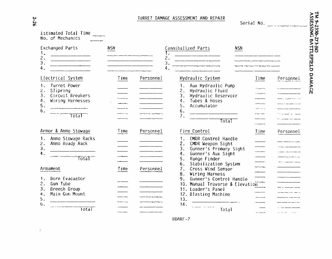
. There are four forms to be used when assessing battlefield damage, BDARF-5,(System Summary), BDARF-6 (Hull Damage Report), BDARF-7 (Turret DamageReport), BDARF-8 (Communications Damage Report). These forms can be used by thecrew, a MT, or a MST.
(1) BDARF-5 is used to determine:
Can the vehicle move, shoot and communicate?
What subsystems are affected?
Is the damage repairable?
If repairable, are there limitations?
Estimated time to repair?2-21

TM 9-2350-273-BDASSESSING BATTLEFIELD DAMAGE
Estimated number of personnel to effect repair.
What materials are required?
Recover status (recovery vehicle required or self-recovery.)
Once these questions are answered, a determination can be made as to whether thevehicle should be repaired on-site, recovered to a collection point and repaired, orrecovered to the rear.
(2) BDARF-6, -7, and -8 address specific systems and subsystems. Theseforms are designed to assist the assessor to rapidly assess the damage and rapidlydetermine the appropriate BDAR fix. The portion of this form which addresses partsshould be filled out only when the tactical situation permits. Where possible theseforms should follow the damaged equipment or be sent to the rear as a record of whatdamages occurred and what repairs were effected and where.
2-22

2-23
TM 9-2350-273-BD

TM 9-2350-273-BD
2-24

TM
9-2350-273-BD
2-25
TM 9-2350-273-BD
2-26

TM 9-2350-273-BD
2-27 (2-28 blank)
BDARF-8

TM 9-2350-273-BD
CHAPTER 3
BDAR FIXES SHALL BE USED ONLY IN COMBATAT THE DISCRETION OF THE COMMANDER
AND SHALL BE REPAIRED BY STANDARD MAINTENANCE PROCEDURESAS SOON AS PRACTICABLE AFTER THE MISSION IS COMPLETED.
SECTION I. General
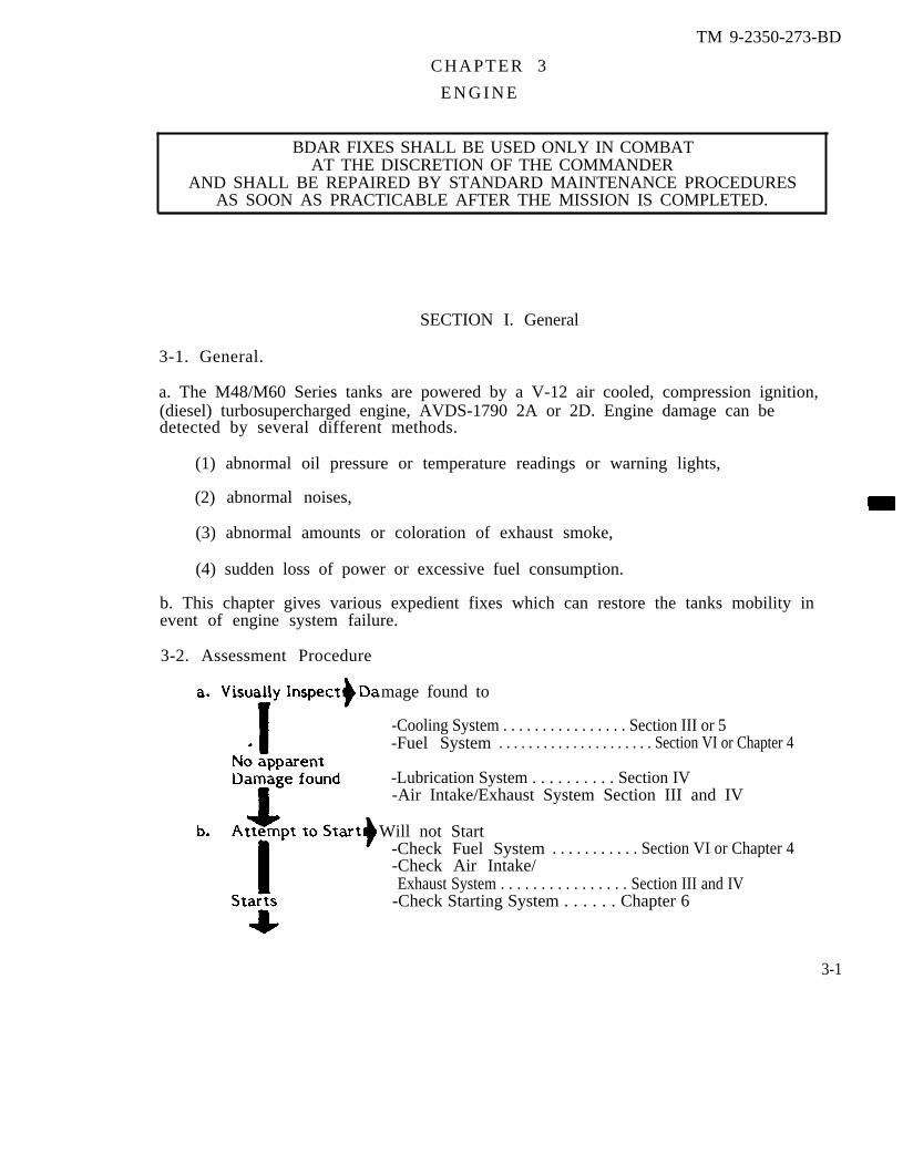
3-1. General.
a. The M48/M60 Series tanks are powered by a V-12 air cooled, compression ignition,(diesel) turbosupercharged engine, AVDS-1790 2A or 2D. Engine damage can bedetected by several different methods.
(1) abnormal oil pressure or temperature readings or warning lights,
(2) abnormal noises,
(3) abnormal amounts or coloration of exhaust smoke,
(4) sudden loss of power or excessive fuel consumption.
b. This chapter gives various expedient fixes which can restore the tanks mobility inevent of engine system failure.
3-2. Assessment Procedure
mage found to
-Cooling System . . . . . . . . . . . . . . . . Section III or 5-Fuel System . . . . . . . . . . . . . . . . . . . . . Section VI or Chapter 4
-Lubrication System . . . . . . . . . . Section IV-Air Intake/Exhaust System Section III and IV
Will not Start-Check Fuel System . . . . . . . . . . . Section VI or Chapter 4-Check Air Intake/Exhaust System . . . . . . . . . . . . . . . . Section III and IV
-Check Starting System . . . . . . Chapter 6
3-1
E N G I N E

TM 9-2350-273-BDENGINE
Damage Detected when Operating or system not
-Mechanical Failures . . . . . . . . ..Section VII-(Internal Engine Failures) ....Section VII-Cooling System Failures.....Section V/Chapter 5-Lubrication SystemFailures . . . . . . . . . . . . . . . . . . . . . . . . . . . .Section IV/Chapter 4
3-3. BDAR Procedure Index. Para.
Engine Inoperative, Engine Interchangeability . . . . . . . . . . . . . . ...3-5Air Cleaner Damaged or Leaking . ......... . . . . . . . . . . . . . . . . . . . . . 3-7Exhaust System Damage . . . . . . . . . . . . . . . . . . . . . . . . . . . . . . . . . . . . . . . . . . . . . . . . 3-9Pump Failure, Lubrication System . . . . . . . . . . . . . . . . . . . . . . . . . . . . . . . . . . 3-11Oil Level Low . . . . . . . . . . . . . . . . . . . . . . . . . . . . . . . . . . . . . . . . . . . . . ......... . . . 3-12Oil Cooler Damage . . . . . . ...... . . . . . . ....... . . . . . . . . . . . . . . . . . . . . . . . . . . 3-13Throttle Linkage Broken . . . . . . . . . . . . . . . . . . . . . . . . . . . . . . . . . . . . . . . . . . . . . . 3-15Engine/Transmission Housing Damage . . . . . . . . . . . . . . . ........ 3-17
WORKING
3 - 2

TM 9-2350-273-BDENGINE
SECTION II. Engine Failure
3-4. General.Basic engines in M48/M60 vehicles are the same but motor supports, manifolds, exhaustor cooling systems require different brackets to fit a particular vehicle. Accessoriesand brackets must be swapped from the unserviceable engine to make the replacementengine fit another application.
3-5. ENGINE INOPERATIVE, ENGINE INTERCHANGEABILITY
General Information:Availability of engines may become restricted to those found in damaged vehicles.Basic engines from other vehicles can be modified or configurations rearranged to fitthe vehicle needing the engine. The AVDS 1790 engine will fit M48A5, M60, M60A1,M60A3, or M88A1. The M88A1 powerpack has a model 1410 transmission, and M48/M60vehicles have a model CD850 transmission. When engines are exchanged, the originaltransmission must be mated to the replacement engine.
Limitations:l None.
Personnel/Time Requiredl 3 soldiers.l 6 hours.
Materials/Tools:l Engine M48/M60 or M88A1.l Lift device.
Other Options:l Remove transmission/final drive connection links and use the vehicle as a towedfiring platform if the firepower systems function. The towed vehicle electrical powerwill rapidly discharge. Use manual controls to conserve power.
Procedural Steps:
1. Remove powerpack.
2. If required, change transmission on powerpack.
3. Transfer needed bracketry, parts and hardware for a specific installation to thesubstitute engine.
a. The 1790-2C engine w/650 AMP generator requires wiring harness 7722353 and1165541.
b. The 1790-2D engine w/300 AMP generator requires wiring harness 11682724and 11672723.
3-3
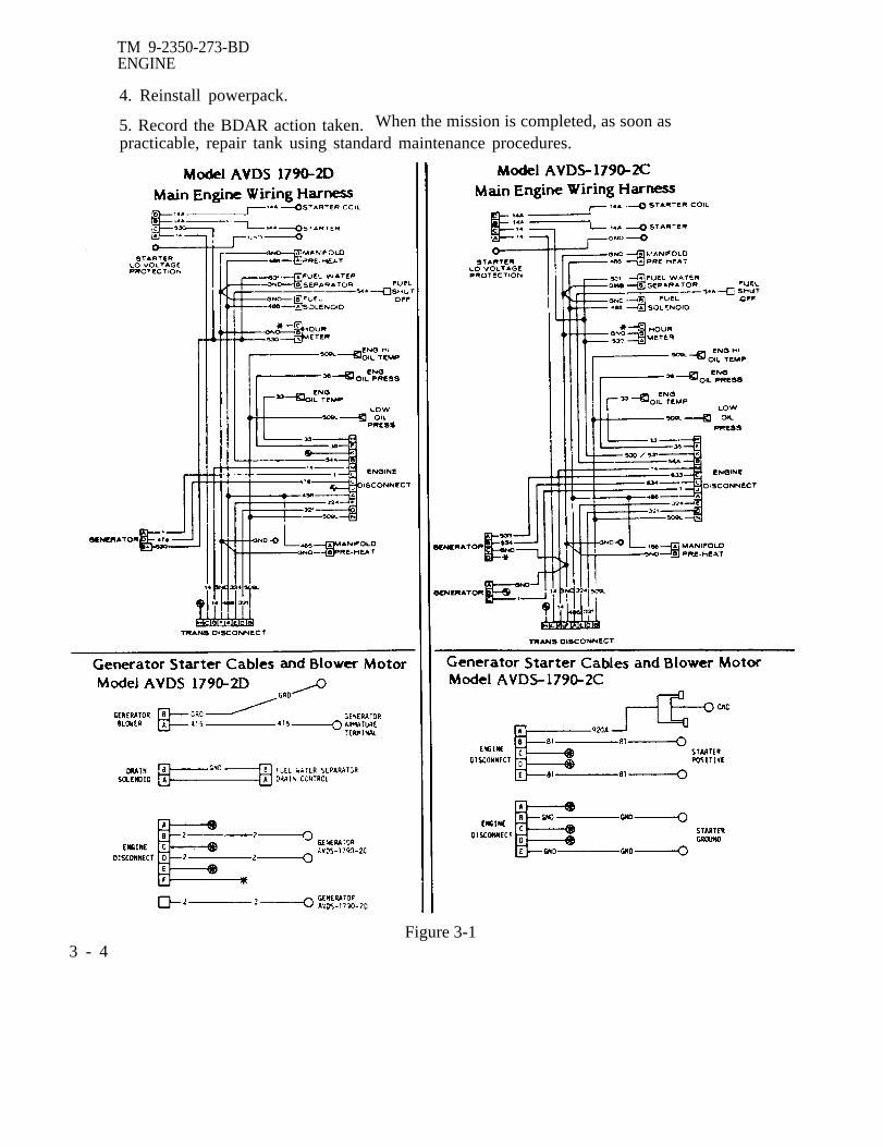
TM 9-2350-273-BDENGINE
4. Reinstall powerpack.
5. Record the BDAR action taken. When the mission is completed, as soon aspracticable, repair tank using standard maintenance procedures.
Figure 3-13 - 4

TM 9-2350-273-BDENGINE
SECTION III. Engine Air Intake Systems
3-6. General.
Turbocharged engines use exhaust gases to drive the turbocharger to compress air andforce it into the cylinder under pressure. The engine air intake system is thereforevacuum and pressure. Repairs to turbocharged air intake systems must be done withmaterials that do not block the air flow. The materials must be securely attached toprevent them from being sucked into the system up to the turbocharger inlet. Therepairs must seal so that the air pressure is maintained from the turbocharger outlet tothe intake manifold.
Figure 3-2. Engine Air Intake.
3-7. AIR CLEANER DAMAGED OR LEAKING
General InformationExternal location makes air cleaner vulnerable to damage. Dust ingestion will causeextensive internal engine wear. Holes or cracks in the air cleaner housing or ductingmust be repaired or covered to keep dirt out of the air intake. Tape, auto body filler orany other available material should be used to seal the air intake system. If the aircleaner or ducting cannot be sealed they should be elimated using this procedure.
Limitations: Degraded air intake efficiency
Personnel/Time Required: 1 soldier 30-60 minutes
3-5

TM 9-2350-273-BDENGINE
Materials/Took Clean rags Cloth Bur lap Fine mesh screen wire
Other Options: Operate for short time periodsof time without air filtration system.
Procedural Steps:
1. Gain access to air inlet by opening top deck grille doors.
2. Remove air inlet hoses, (right and left), if both air cleaners are damaged.
The denser the material, the more it restrictsair intake, thus reducing engine power output.
3. Place cloth or screen wire over air inlet as shown. Secure material with air intakehose clamps or wire to prevent engine from sucking material into engine.
4. Record the BDAR action taken. When the mission is completed, as soon aspracticable, repair tank using standard maintenance procedures.
3 - 6

TM 9-2350-273-BDENGINE
SECTION IV. Engine Exhaust Systems
3-8. General.The engine exhaust system is the exhaust manifold, header pipes, muffler and otherexhaust ducts. Since these engines are turbocharged, the exhaust gases are also routedthrough the turbocharger.
Fig 3-3. M48/M60 Exhaust Systems.
3-9. EXHAUST SYSTEM DAMAGE
General Information:To repair holes or cracks in the exhaust system, cans or similar metal items can be cutand bent to cover holes. A source for the large clamps needed is the generator airducting system of a nonrepairable vehicle. Air ducting is needed to cool thegenerator/alternator. Avoid using the clamp from the tank under repair because if thecooling is disabled, the generator/alternator could be damaged.
Limitations:o Some loss of power at high operating speeds. Generator/Alternator damage ifcooling duct is incomplete.
Personnel/Time Requiredo 2 soldierso less than 2 hours
3 - 7

TM 9-2350-273-BDENGINE
Materials/Tools: Generator air ducting clamps
Other Options: Use welder to repair holes in exhaust system.
Procedural Step:
1. Remove top deck.
2. Locate hose clamp on vehicle that can be removed and is large enough in diameterto fit manifold.
3. Cut can or other metal at least 1/4 inch larger than hole in manifold. Bend metal tofit curve of manifold.
4. When hole is 1/2 inch or less in diameter one hose clamp can be placed aroundmanifold and clamp tightened over the hole.
5. When hole is 1/2 to 1 inch in diameter, cut metal can to a size just larger than thehole. Place metal over the hole and secure with one or two hose clamps.
6. When hole is larger than 1 inch, cut metal can to a size just larger than the hole.Place metal over the hole and secure with two or more hose clamps.
7. Record the BDAR action taken. When the mission is completed, as soon aspracticable, repair tank using standard maintenance procedures.
3 - 8
TM 9-2350- 273-BDENGINE
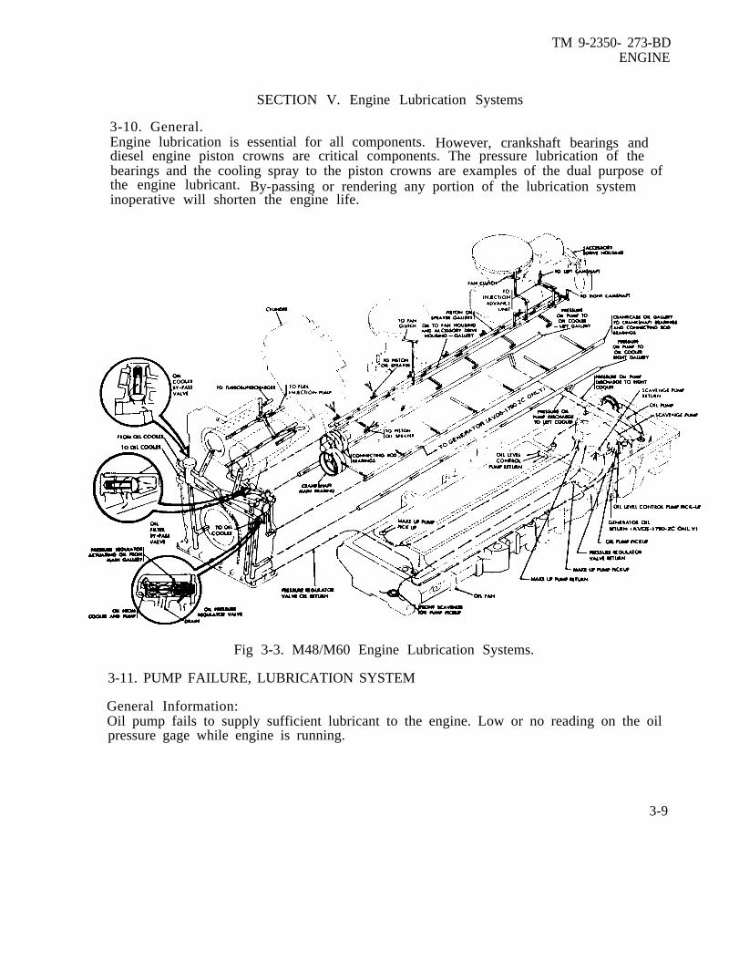
SECTION V. Engine Lubrication Systems
3-10. General.Engine lubrication is essential for all components. However, crankshaft bearings anddiesel engine piston crowns are critical components. The pressure lubrication of thebearings and the cooling spray to the piston crowns are examples of the dual purpose ofthe engine lubricant. By-passing or rendering any portion of the lubrication systeminoperative will shorten the engine life.
Fig 3-3. M48/M60 Engine Lubrication Systems.
3-11. PUMP FAILURE, LUBRICATION SYSTEM
General Information:Oil pump fails to supply sufficient lubricant to the engine. Low or no reading on the oilpressure gage while engine is running.
3-9

TM 9-2350-273-BDENGINE
Limitations: Short moves at low speed only
Personnel/Time Required: 1 soldier 30 minutes
Materials/Tools: Engine oil
NOTE
Transmission oil, other type vehicle oil or dieselfuel may be used when engine oil is not available.
Procedural Steps:
CAUTION
Use this procedure only in extreme emergency and operate thevehicle for short periods of time and at low speeds. The valve trainparts will not be lubricated.
1. Check oil level.
2. Obtain enough engine oil to overfill crankcase by 3 or 4 quarts. New oil or used oilmay be used.
3. Overfill the crankcase. The crankshaft will be submerged in oil and as it rotates itwill splash the lubricant over the main engine parts.
4. Record the BDAR action taken. When the mission is completed, as soon aspracticable, repair tank using standard maintenance procedures.
3-12. OIL LEVEL LOW
General Information:Oil level low in the engine crankcase. Substitute lubricants may be used to raise oillevel. Oils other than those designed for use in engines will provide only limitedlubrication. Driver must employ caution and operate the vehicle at lower revolutionsper minute (RPM) (1600) to prevent damage. Diesel fuel is a thin oil and provides onlylimited lubrication. Do not dilute the lubrication oil more than approximately 3 partsdiesel fuel to 1 part engine oil except in extreme emergencies. Drive slower to preventdamage to the engine. If the engine oil is supplemented with any oil other than thatgiven in the LO, it will be necessary to change the engine oil and filters as soon aspossible.
3-10

TM 9-2350-273-BDENGINE
Limitations:● Reduced lubrication will limit engine life.
Personnel/Time Required:● 1 soldier● 10 minutes
Materials/Tools:● Cooking oil● Diesel fuel● Hydraulic fluid● Used oil
Other Options:● Drain oil from transmission or a hydraulic system and add oil to engine crankcase tobring oil level to at least the ADD OIL mark on gage.
WARNING
Do not mix gasoline with lubricating oil. Gasoline provides nolubrication and could cause an explosion in the crankcase or create afire hazard.
Procedural Steps:
1. Fill the engine crankcase at least to the ADD OIL mark with any availablelubricating oil.
2. Record the BDAR action taken. When the mission is completed, as soon aspracticable, repair tank using standard maintenance procedures.
3-13. OIL COOLER DAMAGE
General Information:Abnormal oil pressure due to a plugged or damaged oil cooler. Operating enginewithout oil cooling will cause engine overheating leading to engine failure.
Limitations:● Self recovery is possible but requires slow speed operation, monitoring of oiltemperatures and frequent stops for engine cooling.
Personnel/Time Required● 3 soldiers● 3 hrs
Other Options:● Continue operations; monitor oil temperature and level.
3-11

TM 9-2350-273-BDENGINE
Procedural Steps:
1. Depending on damage,disconnect either inletor outlet oil coolerline from engine.
2. Disconnect theother line fromcooler and connectto engine.
3. Record the BDARaction taken. Whenthe mission iscompleted, as soonas practicable, repairtank using standardmaintenance procedures.
3-12

TM 9-2350-273-BDENGINE
SECTION VI. Engine Fuel Systems
3-14. General.The engine fuel system provides the pressurized fuel needed for proper operation of acompression ignition engine. An electrical fuel pump provides fuel to the fuel injectionpump which distributes high-pressure fuel pulses to the 12 injectors. The pulse is timedto the compression stroke of the piston in each cylinder. Fuel is injected into thecylinders in the proper quantities to ensure complete combustion. The engine houses awater separator assembly which is equipped with an automatic dump sensor. As watercontacts the sensor the system will drain the contaminated fuel. Three fuel filtersreside the separator ensure that water or other contaminants do not enter the fuelinjection circuit.
Fig 3-4. Engine fuel system.
3-13
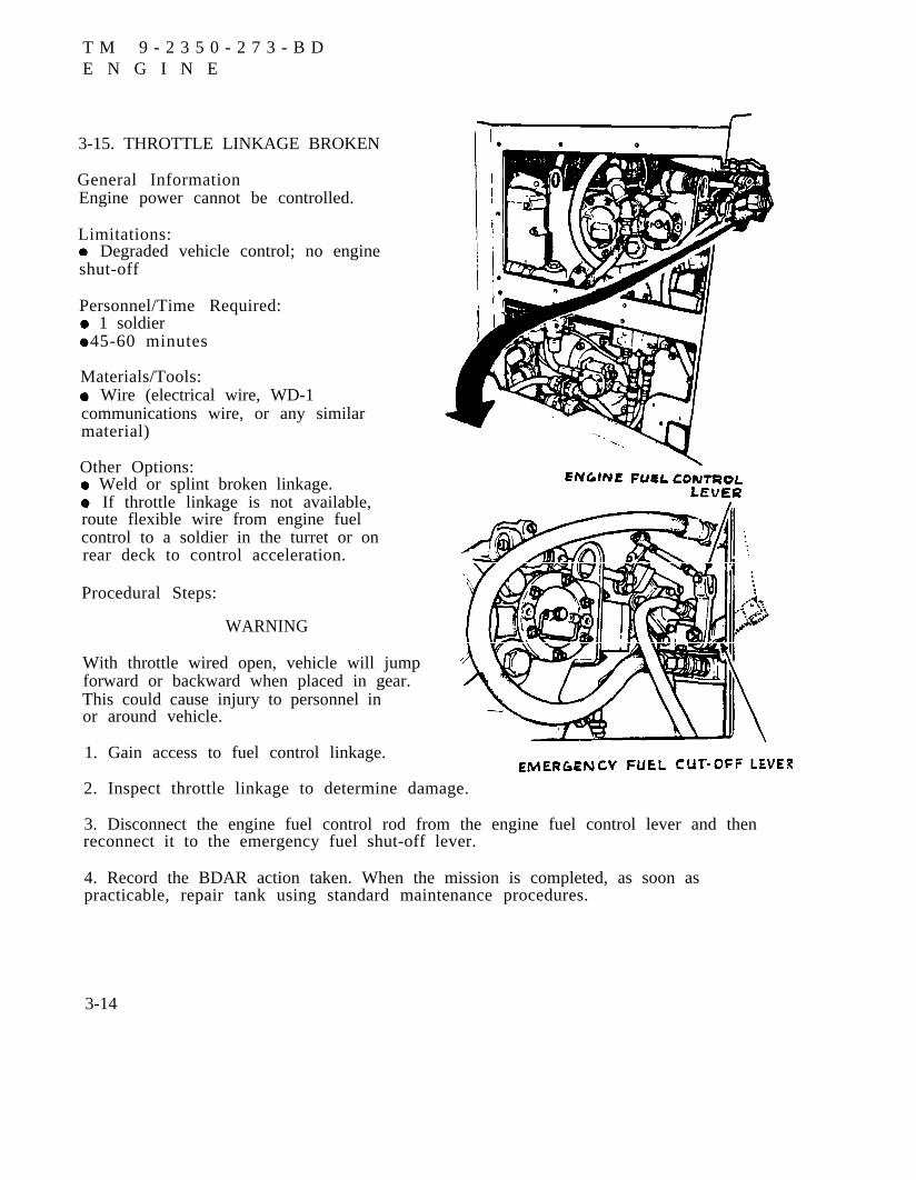
3-15. THROTTLE LINKAGE BROKEN
General InformationEngine power cannot be controlled.
Limitations: Degraded vehicle control; no engineshut-off
Personnel/Time Required: 1 soldier 45-60 minutes
Materials/Tools: Wire (electrical wire, WD-1communications wire, or any similarmaterial)
Other Options: Weld or splint broken linkage. If throttle linkage is not available,route flexible wire from engine fuelcontrol to a soldier in the turret or onrear deck to control acceleration.
Procedural Steps:
WARNING
With throttle wired open, vehicle will jumpforward or backward when placed in gear.This could cause injury to personnel inor around vehicle.
1. Gain access to fuel control linkage.
2. Inspect throttle linkage to determine damage.
3. Disconnect the engine fuel control rod from the engine fuel control lever and thenreconnect it to the emergency fuel shut-off lever.
4. Record the BDAR action taken. When the mission is completed, as soon aspracticable, repair tank using standard maintenance procedures.
3-14
T M 9 - 2 3 5 0 - 2 7 3 - B DE N G I N E

TM 9-2350-273-BDENGINE
SECTION VII. Engine Structure And Internal Components
3-16. General.Engine internal components are not easy BDAR fixes because of the tolerances andbalances necessary to contain the pressure and forces of the burning fuel, and the needfor mechanical integrity of the reciprocating, rotating parts. The best repair forinternal engine components is replacement parts from the supply system.
a. It is possible, however, to mix and match parts from two or more damagedengines to reassemble one good engine with used parts. For example, if one engine hasa damaged cylinder set or top end, the good cylinder/head set can be matched with agood, used short block to build a serviceable spare.
b. Certain internal engine component failures such as cam followers or rockerarm shaft galling may be ignored. Other failures, such as broken rings and galledpistons will result in engine destruction if the vehicle is operated.
Fig. 3-6. Typical Engine Mechanical Construction - Combat Vehicles
3-15

TM 9-2350-273-BDENGINE
3-17. ENGINE/TRANSMISSION HOUSING DAMAGE
General Information:Small cracks or holes may develop in a cylinder block or transmission housing due tovibrations or severe shock forces like mine explosions. Any battle damage to the powerpack should be assessed by the MT.
Limitations: Degraded reliability
Personnel/Time Required: 3 soldiers 12-24 hours
Materials/Tools: Oxy-Acetylene torch for brazing Bulk issue fiberglass or epoxy kit TIG or MIG welding gun for aluminum Permatex, any grade Lift capability
Other Options: Continue operations.
Procedural Steps:
1. Remove power pack when required.
2. Clean damaged area.
3. Fill small cracks or holes in low stress areas either with permatex, fiberglass, orepoxy.
4. Many cracks and holes in stress areas can be repaired by a TIG or MIG welding gunfor aluminum, but precautions must be taken to prevent the housing from warping. Ironcastings can be brazed using an oxy-acetylene torch.
5. Re-install power pack.
6. Record the BDAR action taken. When the mission is completed, as soon aspracticable, repair tank using standard maintenance procedures.
3-16

TM 9-2350-273-BD
CHAPTER 4
FUEL SUPPLY SYSTEM
BDAR FIXES SHALL BE USED ONLY IN COMBATAT THE DISCRETION OF THE COMMANDER
AND SHALL BE REPAIRED BY STANDARD MAINTENANCE PROCEDURESAS SOON AS PRACTICABLE AFTER THE MISSION IS COMPLETED.
SECTION I. General
4-1. General.
The fuel is stored in aluminum fuel tanks located on each side of the powerpack. Each fueltank has an electric fuel pump to provide fuel to the engine. The fuel is routed throughaluminum and steel fuel lines to a paper element fuel filter and then through steelreinforced rubber hoses to another electrical fuel pump on the engine. The engine can drawfuel without the in tank fuel pumps operating but they are needed as a back up system toprovide the fuel requirement of the AVDS 1790 engine.
4 - 1
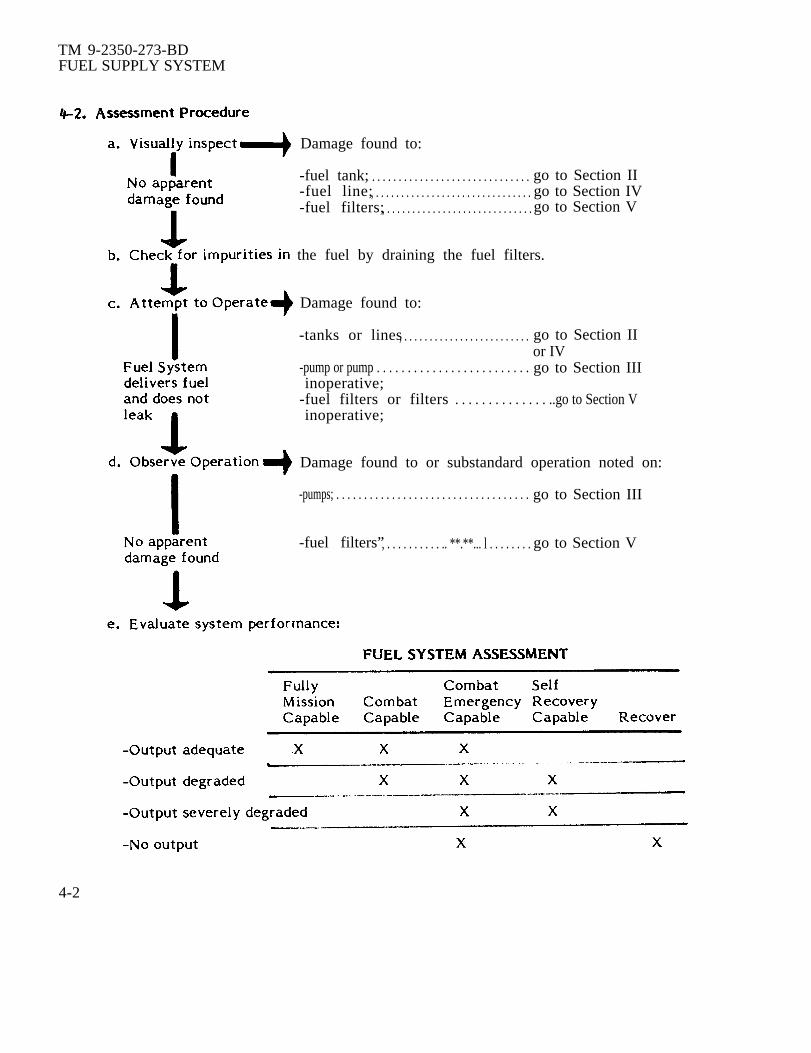
TM 9-2350-273-BDFUEL SUPPLY SYSTEM
Damage found to:
-fuel tank; . . . . . . . . . . . . . . . . . . . . . . . . . . . . . . go to Section II-fuel line;, . . . . . . . . . . . . . . . . . . . . . . . . . . . . . . . go to Section IV-fuel filters;, . . . . . . . . . . . . . . . . . . . . . . . . . . . . . go to Section V
the fuel by draining the fuel filters.
Damage found to:
-tanks or lines, . . . . . . . . . . . . . . . . . . . . . . . . . go to Section IIor IV
-pump or pump . . . . . . . . . . . . . . . . . . . . . . . . . go to Section IIIinoperative;
-fuel filters or filters . . . . . . . . . . . . . . ..go to Section Vinoperative;
Damage found to or substandard operation noted on:
-pumps; . . . . . . . . . . . . . . . . . . . . . . . . . . . . . . . . . . . go to Section III
-fuel filters”, . . . . . . . . . . .. **.**... l . . . . . . . . go to Section V
4-2

TM 9-2350-273-BDFUEL SUPPLY SYSTEM
4-3. BDAR Procedure IndexPara.
Fuel Tank Substitute . . . . . ..... . . . . . . . . . . . . . . . . . . . . . . . . . . . . . . . . . . . . . . . . . . . . . . . . . . . . . . . . .4-5Fuel Dump (In-Tank) Inoperative . . . . . . . . . . . . . . . . . . . . . . . ..... . . . . . . ........ . . . . . . . . . . 4-7Fuel Line Frozen . . . . . . . . ...... . . . . . . . . . . . . . . . . . . . . . . . . . . . . . . . . . . . . . . . . . . . . . . . . . . . . . . . . . . . . 4-9Fuel Filter Clogged or Frozen . . . . . . . . . . . . . . . . . . . . . . . . . . . . . . . . . . . . . . . . . . . . . . . . . . . . . . . . . . 4-11
4-3

TM 9-2350-273-BDFUEL SYSTEM SUPPLY
SECTION II. Fuel Storage Systems.
4-4. General.Fuel is stored in enclosed aluminum containers. Fuel tanks are susceptible tocontamination from dirt, water or other impurities. The fuel tanks are susceptible tocorrosion which may result in leaks. Purging a contaminated fuel system and repairingleaks are the prime BDAR solutions. The tank is particularly susceptible to cracks.
&5. FUEL TANK SUBSTITUTE
General InformationFuel tank is damaged beyond immediate repair, a temporary tank may be used. Anysuitable container, such as a 5-gallon gas or oil can, a 55 gallon drum, etc, can besecured to the outside of the vehicle in a position above the engine.
Limitations: Turret traversing will be limited. Frequent refueling required.
P e r s o n n e l / R e q u i r e d : 2 soldiers 1 to 1-1/2 hours
Materials/Tools: Rubber fuel line Wood blocks Rope or straps
Procedural Steps:
1.
2.
3.
4.
5.
6.
Secure container on outside of tank using wood blocks and rope.
Obtain fuel line or hose and secure it to the container.
Gain access to the engine mechanical fuel pumps.
Disconnect the fuel line at the fuel inlet connector as shown.
Connect the fuel line from the container to the fuel inlet connection.
Fill the container with fuel and purge the air from the fuel line, tighten connection.
4 - 4

TM 9-2350-273-BDFUEL SUPPLY SYSTEM
7. Tie or block the engine access doors to protect the fuel line from damage.
8. Record the BDAR action taken. When the mission is completed, as soon aspracticable, repair tank using standard maintenance procedures.
4-5

TM 9-2350-273-BDFUEL SUPPLY SYSTEM
SECTION III. Fuel Pumps
4-6. General .Engine will not start, no fuel to injector pump. The in-tank fuel pumps are generallyinterchangeable between combat vehicles. The difference is in the bracketry used tomount the pump in the fuel tanks. The electrical pump unit can be removed and used onthe brackets to fit the M48/M60 series tank.
4-7. FUEL PUMP O N-T A NK) I NOPERATIVE
General Information:Engine will not start, no fuel to injector pump. Install a substitute fuel pump. Thein-tank fuel pumps are generally interchangeable between combat vehicles.
Limitations: None
Personnel/Time Required: 2 soldiers 3 hours
Materials/Tools: In-tank fuel pump from any of the following
- 2-1/2 ton truck- 5 ton truck- M109/Ml 10 SP Howitzer- M 1 tank
Other Options:l Use the heater’s fuel pump to provide fuel to the engine.
Procedural Steps:NOTE
If engine stops, check fuel valve to assurevalve is in “BOTH” position. If fuel flow valveis in “BOTH” position, both pumps have failed.Only one fuel pump is needed to supply fuel tothe engine with fuel flow valve in “BOTH” postion.
1. Gain access to left or right engine compartment (in-tank) fuel pump mounting coverassembly that has defective fuel pump.
2. Remove fuel pump cover assembly with attached defective fuel pump. Removedefective pump from cover assembly.
4 - 6
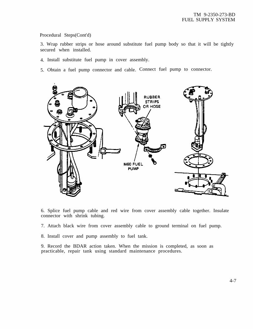
TM 9-2350-273-BDFUEL SUPPLY SYSTEM
Procedural Steps(Cont'd)
3. Wrap rubber strips or hose around substitute fuel pump body so that it will be tightlysecured when installed.
4.
5.
Install substitute fuel pump in cover assembly.
Obtain a fuel pump connector and cable. Connect fuel pump to connector.
6. Splice fuel pump cable and red wire from cover assembly cable together. Insulateconnector with shrink tubing.
7. Attach black wire from cover assembly cable to ground terminal on fuel pump.
8. Install cover and pump assembly to fuel tank.
9. Record the BDAR action taken. When the mission is completed, as soon aspracticable, repair tank using standard maintenance procedures.
4-7
TM 9-2350-273-BDFUEL SUPPLY SYSTEM
SECTION IV. Fuel Lines And Valves
4-8. General.Any fix which will stop leaks or by-pass a blocked line is acceptable. Metal and rubberline repairs are covered in TM 9-2350-276-BD.
4-9. FUEL LINE FROZEN
General Information:Engine will not start because of frozen fuel lines. Diesel fuel may accumulate water bycondensation causing a freezing problem during cold weather. Fuel tanks should bechecked for water.
Limitations: None
Personnel/Time Required: 2 soldiers 30 to 60 minutes
Materials/Tools: Air duct tubing
Other Options: Use a Herman Nelson heater to warm the lines. Use another vehicle’s exhaust to heat the lines.
Procedural Steps:
1. Disconnect heater air duct tubing at personnel heater.
2. Route a long duct or connect a series of short ducts long enough to reach the frozenarea.
3. Start personnel heater and heat the frozen lines.
4. Attempt to start engine,
5. After the engine starts, purge water from fuel system.
6. Record the BDAR action taken. When the mission is completed, as soon aspracticable, repair tank using standard maintenance procedures.
4-8

TM 9-2350-273-BDFUEL SUPPLY SYSTEM
Section V. Fuel Filters
4-10. General.There are 2 filter devices in the fuel system. The primary filter is on the engine and 3filter elements are in the fuel water separator also on the engine. The filters must beperiodical y drained to prevent water or dirt from entering the engine fuel system.
4-11. FUEL FILTER CLOGGED OR FROZEN
General InformationClogged or frozen fuel filters will stop the flow of fuel to the injector pump. Lack offuel will stop the engine from running or if frozen will prevent the engine from starting.Clogged filters must be repaired or by-passed and frozen filters must be thawed.
Limitations: Unfiltered fuel if filters are bypassed.
Personnel/Time Required: 1 soldier 60 minutes
Materials/Tool* None
Other Options For frozen filters, heat with the personnel heater air ducted to the enginecompartment or heat with another vehicle's exhaust.
For clogged filters, remove filter element.
Procedural Steps:
1. Gain access to the fuel filters.
2. Clean away all grease and oil from filter connectors.
3. Drain the fuel lines and filter canisters.
4. Check for fuel leakage, tighten connections if required. Purge fuel lines; if thefailure is not corrected, go to step 5.
5. Primary filter may be by-passed by disconnecting lines from filter and connectingthem together as shown.
4-9

TM 9-2350-273-BDFUEL SUPPLY SYSTEM
Procedural Steps (Conf'd)
6. The secondary filter may be by-passed by disconnecting the main injector supply linefrom the filter and connecting it directly to fuel pump line using the existing elbow .
7. Check for fuel leakage after by-passing the filter.
8. Record the BDAR action taken. When the mission is completed, as soon aspracticable, repair tank using standard maintenance procedures.
4-10

TM 9-2350-273-BD
C H A P T E R 5
COOLING SYSTEM
BDAR FIXES SHALL BE USED ONLY IN COMBATAT THE DISCRETION OF THE COMMANDER
AND SHALL BE REPAIRED BY STANDARD MAINTENANCE PROCEDURESAS SOON AS PRACTICABLE AFTER THE MISSION IS COMPLETED.
SECTION I. General
5-1. General. Cooling system problems may be indicated by a variety of faults.Typically the driver’s indicator panel will show overheating. However, sporadicoverheating or constant high temperature may indicate an impending major coolingsystem problem.
5-2. Assessment Procedure
Damage found to:
-fans; . . . . . . . . . . . . . . . . go to Para 5-4
-fan drive; . . . . . . . . . go to Para 5-4
-shrouds; . . . . . . . . . . go to TM 9-2350-276-BD
-ducts; . . . . . . . . . . . . . go to TM 9-2350-276-BD
-engine . . . . . . . . . . . ..go to TM 9-2350-276-BDcompartment covers;
-engine . . . . . . . . . . . ..go to TM 9-2350-276-BDcompartment seals;
Damage found to:
-fan air intake; . . go to Para 5-4
-fan drive; . . . . . . . . go to Para 5-4
-engine . . . . . . . . . . . ..go to TM 9-2350-276-BDcompartment covers;
-engine . . . . . . . . . . . ..go to TM 9-2350-276-BDcompartment seals;
5-1

TM 9-2350-273-BDCOOLING SYSTEM
c. Evaluate system performance:
Note 1
Careful operation under these conditions will not damage the engine if it is operatedonly to reposition or move the vehicle under light acceleration for short periods oftime. The engine oil temperature must be allowed to cool to under 200°F betweenoperations.
5-3. BDAR Procedure Index. Para.
Cooling Fan Failure . . . . . . . . ..... . . . . . . . . . . . . . . . . . . . . . . . . . . ... . . . . . . . . . . . . . . 5-4
5 - 2

TM 9-2350-273-BDCOOLING SYSTEM
SECTION II. BDAR Procedures
5-4.. COOLING FAN FAILURE
General Information:The AVDS-1790 engine utilizes two cooling fans. The fan at the front of the engineprimarily cools the engine oil coolers. The rear fan cools the transmission oil coolers.A damaged fan should be replaced. However, the transmission can function muchlonger at a higher temperature than the engine. The rear fan can be installed on thefront drive. However, the rear fan drive must not be disabled because it drives theengine fuel injector pump. Fans from AVDS-1790 series engines are interchangeable onthe M48A5, M60, M60A1, M60A3, and M88A1 vehicles. If a fan is defective operate atlow speeds and monitor power pack oil temperatures.
Limitation: Reduced mobility
Personnel/Time Required: 2 to 3 soldiers Less than 2 hours
Materials/Tools: Replacement fan, or rear fan Spacer, fan hub sleeve, NSN 4910-00-795-7952
Procedural Steps:
1. Remove rear deck.
2. Remove defective fan assembly.
3. When replacement fan is not available,replace the front fan with rear fan. Theoverflow of air from front fan will helpcool the transmission.
4. Install the fan spacer in place ofthe removed fan.
5-3

TM 9-2350-273-BDCOOLING SYSTEM
Procedural Steps (Cont'd)
5. Reinstall rear deck.
6. When both fan assemblies are defective, the vehicle must be recovered.
7. Record the BDAR action taken. When the mission is completed, as soon aspracticable, repair tank using standard maintenance procedures.
5 -4

TM 9-2350-273-BD
C H A P T E R 6
ELECTRICAL SYSTEM
BDAR FIXES SHALL BE USED ONLY IN COMBATAT THE DISCRETION OF THE COMMANDER
AND SHALL BE REPAIRED BY STANDARD MAINTENANCE PROCEDURESAS SOON AS PRACTICABLE AFTER THE MISSION IS COMPLETED.
SECTION I. General
6-1. General.The electrical system is a 24-volt direct current power supply. Storage is provided bysix 12-volt batteries located to the rear of the driver under the turret basket floor.Recharging is provided by either a 650 AMP oil cooled alternator or a 300 AMP aircooled AC generator. A slave receptacle is provided for emergency power should thevehicle’s power fail. The starter is a 24 vDC electric motor protected by a neutralsafety switch which prevents starter operation unless the transmission is in neutral.Circuit protection is provided by circuit breakers. When tripped, the circuit breakerswill automatically reset as they cool down.
6-2. Assessment Procedure
damage found to:
-batteries; . . . . . . . . . go to TM 9-2350-276-BD-cables; . . . . . . . . . . . . . go to Section II-wiring, . . . . . . . . . . . . go to Section II-circuit . . . . . . . . . . . . go to TM 9-2350-276-BDbreakers;
-voltage . . . . . . . . . . . go to Section IIIregulator
-alternator; . . . . . . go to Section III
-alternator . . . . . . . . . . . . . . . . . . . . .go to Section IIIoutput function;
-voltage . . . . . . . . . . . . . . . . . . . . . . . . . go to Section IIIregulator function
-circuit breakers . . . . . . . . . . . . go to TM 9-2350-276-BD
6-1

TM 9-2350-273-BDELECTRICAL SYSTEM
c. Evaluate system performance:
6-3. BDAR Procedure Index. Para.
Alternator Interchangeability . . . . . . . . . . . . . . . . . . . . . . . . . . . . . . . . . . . . . ..... . . . . . . . . . . . . . . . . . . . . .6-6Emergency Tow Starting, At Reduced Speed . . . . . . . . . .... . . . . . . . ...... . . . . . . . . . . . . . .. 6-7Starter Failure . . . . . . . . . . . . . . . . . . . . . . . . . . . . . . . . . . . . . . . . . . . . . . . . . . . . . . . .... . . . . . . ....... . . . . . . . . . . ... 6-8Engine Starter Will Not Energize, Defective Neutral Safety Switch ................... . . . . . . . ...6-9Turret, No Hydraulic Power . . . . . . . . . . . . . . . . . . . . . . . . . . . . . . . . . . . . . . . . . . . . . . . . . . . . . . . . . . . . . . . . . . .6-10
6-2

TM 9-2350-273-BDELECTRICAL SYSTEM
SECTION II. General Electrical Repair
6-4. General.Electrical repairs fall into several categories.
a. By-passing a switch or system.
b. Substituting with a like item or lower powered item.
c. Isolating a circuit.
The priority of the function, available tools and parts will dictate the type of repair tobe attempted. General electrical repair procedures are given in TM 9-2350-276-BD.Electrical components which are interchangeable may be found in Appendix A or thefollowing sections of this chapter.
6-3

TM 9-2350-273-BD .ELECTRICAL SYST'EM
SECTION 111. Motors, Starters, Alternators
6-5. General.Repair on automotive motors should be limited to relays, solenoids and brushes.Damage to casings and windings cannot be expediently repaired.
6-6. ALTERNATOR INTERCHANGEABILITY
General Information:Alternator failure will degrade the vehicle’s combat operations. Emergency usage onbattery power is only operation possible, but will require frequent recharging fromanother vehicle or an outside power source. The alternator should be replaced.
Limitations: None
Personnel/Time Required: 2 soldiers 4 hours
Materials/Tools: Cannibalized alternator Corresponding regulator
Other Options: Vehicle can be driven without alternator
Procedural Steps:
1. Remove power pack.
2. Obtain alternator from another vehicle or unserviceable engine.
3. Examine the replacement alternator to determine if it is an exact replacement. Ifthe exact replacement cannot be found, the AVDS 1790-2D alternator can beinterchanged with the AVDS 1790-2C alternator.
NOTE
Interchanging alternators requires the exchange of engine wiring harnesses 7722353 and1165541 (AVDS 1790-2C) with 11682724 and 11672723 (AVDS 1790-2D). The voltageregulator must also be changed if changing the wiring harnesses and alternator (Seefigure 3- 1).
Interchanging alternators also requires the installation or removal of oil cooledalternator cooler hoses or air cooling ductwork. Utilize as many parts as possible fromthe same source.
6-4

TM 9-2350-276-BDELECTRICAL SYSTEM
Procedural Steps (Cont'd)
4. Re-install power pack.
5. Record the BDAR action taken. When the mission is completed, as soon aspracticable, repair tank using standard maintenance procedures.
6-7. EMERGENCY TOW STARTING , AT REDUCED SPEED
General Information:Loss of electrical power or starter failure in degraded towing environments will preventnormal tow start operations. The vehicle can be tow-started at speeds as low as 10mph.
Limitations None.Personnel/Time Required: 3 soldiers 30 minutes
Materials/Tools: Tank or other vehicle capable of towing the tank Tow cables
Procedural Steps:
1.
2.
3.
CAUTION
to 10 MPH minimum
Equipment damage may result if the right steer is not releasedpromptly after engine starts. Failure to release right steer controlwill apply excessive pressure on steering system causing oversteer ofvehicle when engine is started.
Connect the disabled vehicle front to rear of tow vehicle with tow cables.
Bring vehicle speed to 10 MPH minimum.
WARNING
If the right steer is not released promptly,personnel may be injured by being jerked againstthe vehicle or by flying objects caused by violentvehicle movement.
Shift the towed tank into the lowest forward gear and apply hard right steer. Thehard right steer will double the transmission pump rate and- crank the engine fastenough to start.
6-5

TM 9-2350-273-BDELECTRICAL SYSTEM
Procedural Steps (Cont’d)
4. As soon as the engine starts, release the right steer.
5. Stop vehicles and disconnect tow cables or tow bar.
6. Record the BDAR action taken. When the mission is completed, as soon aspracticable, repair tank using standard maintenance procedures.
6-8. STARTER FAILURE
General InformationStarter will not operate. Replace starter with cannibalized starter from M48A5,M60A1, M60A3, M88A1, AVLB or CEV.
Limitations: None
Personnel/Time Required: 3 soldiers 3-4 hours
Materials/Tools: Starter Lift capability
Other Option: Tow Start
Procedural Steps:.
1. Remove power pack.
2. Remove defective starter.
3. Install the new or used starter cannibalized from one of the vehicles with an AVDS-1790 engine.
4. Re-install power pack.
5. Record the BDAR action taken. When the mission is completed, as soon aspracticable, repair tank using standard maintenance procedures.
6-9. ENGINE STARTER WILL NOT ENERGIZE, DEFECTIVE NEUTRAL SAFETYSWITCH
General Information:If the engine starter will not energize because the neutral safety switch is defective;the neutral safety switch can be replaced with the rear deck clearance switch.6-6

TM 9-2350-273-BDELECTRICAL SYSTEM
Limitations Equipment fail-safe system neutralized when deck clearance switch is removed.
Personnel/Time Required: 1 soldier 30-60 minutes
Materials/Tools: Safety switch Tape
Other Options:
or deck clearance switch
The vehicle will start in any gear when theneutral safety switch has been by-passed.Accidental starts may cause death to personnalfront of vehicle.
l By-pass the neutral safety switch byconnecting the wires together.
Procedure Steps:
1. Remove defective safety switch.
2. Install another neutralsafety switch or replace it with thedeck clearance switch if a switchis not available.
CAUTION
Operation of vehiclewithout a deck clearanceswitch could cause equipmentdamage.
3. Record the BDAR action taken.When the mission is completed, assoon as practicable, repair tankusing standard maintenance procedures.
6-7

TM 9-2350-273-BDELECTRICAL SYSTEM
SECTION IV.
6-10. TURRET, NO HYDRAULIC POWER
General Information:
Turret Power
The turret hydraulic power is needed to operate the turret. The manual back-up systemcan be used without the main hydraulic power being functional but the operation wouldbe seriously degraded. The stabilization system will be inoperative. This procedure willgive a method to power up the hydraulic system.
Limitations None
Personnel/Time Required 2 soldiers 1 to 2 hours
Materials/Tools Mul t imeter Tape Soldering iron
Assessment Steps:
1. Turn MASTER power switch ON.
2. Check that ELEV/TRAV power indicator light lights.
a. If yes, go to step 13.b. If no, go to step 3.
3. Turn MASTER power switch OFF.
6-8

TM 9-2350-273-BDELECTRICAL SYSTEM
Assessment Steps (Cont'd)
4.
5.
6.
7.
8.
9.
10.
11.
12.
Disconnect turret power cable at turret power relay box, connector 31.
Turn MASTER power switch ON.
Check for power at turret power cable connector.
a. If power is present, go to step 70
b. If power is not present, repair turret power cable.
Reconnect turret power cable.
Disconnect turret control wiring harness from connector J3.
Check for power at socket B of connector J3 on the turret relay box.
a. If power is present, go to step 13.b. If power is not present, go to step 10.
Remove cover of turret power relay box.
Remove wire (CKT 625) from circuit breaker.
Connect this wire to circuit breaker bus bar using existing screw.
6-9

TM 9-2350-273-BDELECTRICAL SYSTEM
Assessment Steps (Cont'd)
13. Remove hydraulic pump motor cable from connector J2 on turret power relay box.
14. Check for power at connector J2.
a. If power is present, repair the hydraulic pump motor or use manual back-upsystem.b. If power is not present, go to step 15.
15. Reconnect hydraulic pump motor cable.
6-10
TM 9-2350-273-BDELECTRICAL SYSTEM
Assessment Steps (Cont'd)
16. Disconnect pressure switch connector.
17. Check for power at socket A.
a. If power is present, go to step 18.b. If power is not present, repair turret control wiring harness or use manualback-up system.
18. Using ohms scale check pressure gauge (pressure below 1225 psi).
19. Check for continuity through pressure switch.
a. If present, go to procedural step 1.b. If not present, replace pressure switch or use manual power.
Procedural Steps
1. Remove cover from turret power relay box.
2. Check continuity of power control circuit breaker across bus bars and across wireterminals S1 and S2.
a. If present at both checks, replace power relay or use manual power.b. If not present, go to step 3.
3. Remove one leg of power lead (CKT 100) from bus bar.
4. Connect to bus bar between defective circuit breaker and power relay.
5. Remove wire from terminal S1 and connect to terminal S2 using existing screw.
6. Record the BDAR action taken. When mission is completed, as soon as practicable,repair tank using standard maintenance procedures.
6-11
(6-12 blank)

TM 9-2350-273-BD
CHAPTER 7
P O W E R T R A I N / S T E E R I N G
BDAR FIXES SHALL BE USED ONLY IN COMBATAT THE DISCRETION OF THE COMMANDER
AND SHALL BE REPAIRED By STANDARD MAINTENANCE PROCEDURESAS SOON AS PRACTICABLE AFTER THE MISSION IS COMPLETED.
SECTION I. General
7-1. General.The powertrain consists of a CD850-6A two-speed forward, one-speed reverse,automatic transmission which delivers power to two final drives to drive the tracks.The CD850 transmission houses the steering mechanisms and brake bands. Thetransmission provides the tank with a neutral steer capability which allows it to turn inits own radius by driving one track forward and the other in reverse.
7-2. Assessment Procedure.
a. Pre-conditions: Vehicle brakes should be in working condition. The vehicleengine must run to assess the powertrain using this procedure.
-housings; . . . . . . . . . . . . . . . . . . . . . . . ..go to Para 3-17-drives;.............................. .....go to Section III-linkages; . . . . . . . . . . . . . . . . . . . . . . . . . go to Section IV or
TM 9-2350-276-BD
damage found to:
-forward gears; . . . . . . . . . . . . . . . . go to TM 9-2350-276-BD-reverse gears; . . . . . . . . . . . . . . . . . . go to TM 9-2350-276-BD-steering capability ; . . . . . . . . . . . . go to Section IV
7-1
TM 9-2350-273-BDPOWERTRAIN/STEERING
Assessment Procedure Cont.
d. Check Powertrain/steering performance:
POWERTRAIN/STEERING ASSESSMENT
-All gears and steering
-Reverse, one forward gearand steering
-One gear only and steering
-One gear only; no steering
-No gears, no steering
Note 1
Fully Combat SelfMission Combat Emergency RecoveryCapable Capable Capable Capable Recover
Use as towed platform or stationary gunumount.
7-3. BDAR Procedure Index: Para
Transmission Slippage . . . . . . . . . . . . . . . . . . . . . . . . 7-4Final Drive Mounting Studs Broken or Sheared . . . . . . . . . . . ...7-5Steering Linkage Failure . . . . . . . . . . . . . . . . . . . . . . . . . . ...7-6
7-2

TM 9-2350-273-BDPOWERTRAIN/STEERING
SECTION II. Transmission
7-4. TRANSMISSION SLIPPAGE
General InformationWhen the transmission is slipping, the engine overspeeds relative to vehicle movement.The procedure below is the only known battlefield expedient that can be performed onthe transmission in less than 2 hours to correct transmission slippage. The transmissionconverter pressure must be raised to above 60 psi for transmission to operate. Drainingand replacing transmission oil with OE 30 or OE 50 oil will not correct transmissionslippage caused by pump or disk wear.
Limitations Potentially short transmission service life.
Personnel/Time Required: 2 soldiers 2 hours
Materials/Tool: Steel washer; minimum l/2-inch inside diameter, maximum l-inch outside diameter.
Procedural Steps:
NOTE
This procedure will increase the pressure to theconverter approximately 10 psi per washer and raise theconverter pressure above 60 psi. Transmission will notoperate if pressure is below 60 psi.
1. Remove two flat washers fromhydraulic power pack side mount.Re-install bolts and lock washersin side mount.
2. Gain accessvalve body.
7-3
TM 9-2350- 273-BDPOWERTRAIN/STEERING
Procedural Steps (Cont’d)
3. Remove cap frorn converter controlvalve located on side of valve body.
4. Pull out piston and spring inside valve body.
5. Remove the spring but leave existingwashers on piston.
6. Install the two washers, removed fromhydraulic power pack, on top of the existing washers.
7. Re-install spring on piston and place the large diameter end of piston in the cap.
8. Insert the piston and cap into the valve body and re-tighten the cap.
9. Record the BDAR action taken. When the [mission is completed, as soon aspracticable, repair tank using standard maintenance procedures.
7-4

TM 9-2350-273-BDPOWERTRAIN/STEERING
SECTION III. Final Drive
7-5. FINAL DRIVE MOUNTING STUDS BROKEN OR SHEARED
General Information:Loose final drive mounting studs can cause the final drive to work loose and shear thestuds. Severe damage to the transmission, final drive and/or track may result if thedamage is not repaired promptly.
Limitations: Option 1: None with a complete set of replacement studs; if less then a completeset, degraded mobility. Option 2: Welded repair requires periodic inspection.
Personnel/Time Required: 2 soldiers 4 hours per final drive
Materials/Tools: Replacement stud(s) Welding equipment Lift capability
Procedural Steps:
Option 1
1. Break track and remove sprocket and hub assembly from final drive.
2. Remove broken/sheared studs from final drive.
3. Install replacement bolts or studs (use every other stud from the opposite final driveif required).
4. Re-install sprocket and hub assembly.
5. Reconnect track and adjust tension.
Option 2.
1. Break track and remove sprocket and hub assembly from final drive.
2. Ensure that the final drive housing is seated to the hull, and weld the final drivehousing to the hull.
3. Re-install sprocket and hub assembly.
7-5

TM 9-2350- 273-BDPOWERTRAIN/STEERING
Procedural Steps (Cont'd)
4. Reconnect track and adjust tension.
Record the BDAR taken. When the mission is completed, as soon as practicable, repairtank using standard maintenance procedures.
7-6

TM 9-2350-273-BDPOWERTRAIN/STEERING
SECTION IV. Steering Systems
7-6. STEERING LINKAGE FAILURE
General InformationUnable to control vehicle, no steeroperating the push rods.
Limitations:● Degraded mobility
Personnel/Time Required● 2 soldiers● 30 minutes
Materials/Tool:● Cannibalized linkage assembly
Other Options:● Weld or splint linkage using proceduresfor linkage repair inTM 9-2350-276-BD.
Procedural Steps:
WARNING
Do not move turret whilemanually steering the vehicle.Turret movement could result insevere injury or death.
1. To steer vehicle with broken linkage, station a crew member on the left side ofturret for access to the linkage.
b. Push the steering rod to the rear to turn the vehicle left.
b. Pull the steering rod forward to turn the vehicle right.
2. Maintain communications with the driver by intercom for instructions.
3. Record the BDAR action taken. When the mission is completed, as soon aspracticable, repair tank using standard maintenance procedures.
7-7(7-8 blank)
ing capabilities. Steer the vehicle by manually


TM 9-2350-273-BD
C H A P T E R 8
B R A K E S
BDAR FIXES SHALL BE USED ONLY IN COMBATAT THE DISCRETION OF THE COMMANDER
AND SHALL BE REPAIRED BY STANDARD MAINTENANCE PROCEDURESAS SOON AS PRACTICABLE AFTER THE MISSION IS COMPLETED.
SECTION I. General
8-1. General.The vehicle service brake is a hydromechanical system. A master cylinder and twoslave cylinders are used to apply the brake bands-inside the transmission and stop thetank. The steering system uses braking action to steer the tank by applying brakingaction to one side or the other. This allows the steering to be used to stop the tankshould the hydraulic brake system fail. The parking brake has mechanical linkage to thetransmission which locks the transmission in a braked condition.
8-2. Assessment Procedure
a. Assessment Preconditions: Before testing the vehicle brakes, clear theimmediate area or, if in a restricted area, restrain the vehicle to be tested withchains or cables. The brakes can be tested using either the test vehicle power or itcan be towed by the restraining vehicle up a slight grade for the test.
Damage found to;
-pedal and linkage; . . . . ..go to TM 9-2350-276-BD-hydraulic lines; .............. go to TM 9-2350-276-BD-brake cylinders; . . . . . . . . go to Section II
Damage found to:
-no stopping power; . . . . go to Section II
-pulling or other . . . . . . . . go to Section IIerratic action; or TM 9-2350-276-BD
-parking brakes; . . . . . go to Section II
8-1

TM 9-2350-273-BDBRAKES
d. Evaluate performance
BRAKE ASSESSMENT
Fully CombatMission Combat Emergency SelfCapable Capable Capable Recovery Recover
-Brakes normal
-Brakes degraded
-Brakes severelydegraded
-No brakes
8-3. BDAR Procedure Index
Brake Master Cylinder Failure . . . . . . . . . . . . . . . . . . . . . . . . . . . . 8-5Brakes Locked, Linkage Jammed . . . . . . . . . . . . . . . . . . . . . . . . . 8-6Brake Fluid Leakage at Transmission Slave Cylinder . . . . . . . . . 8-7
8-2

TM 9-2350-273-BDBRAKES
SECTION II. Brake BDAR8-4. General.The service brakes are actuated by a master cylinder and two slave cylinders. Cylinderleakage and internal corrosion are the most common modes of failure. Several methodsare available to regain the use of the brakes if repair parts are not available.
8-5. BRAKE MASTER CYLINDER FAILURE
General InformationMaster cylinder failure will degrade the stopping capability of the tank. The mastercylinder should be replaced with a new or substitute item. A 5-ton truck mastercylinder is physically the same on the outside. The internal fluid return ports aredifferent but the bore diameter is the same. The piston cups are the same as those onM48/M60.
Limitations● None
Personnel/Time Required● 1 soldier● 2 hours
Materials/Took● Repair kit for master cylinder● A 5-ton truck master cylinder
Other Options● Disassemble master cylinder and clean.● Use hills to slow or stop tank.● Brush against other objects, trees, earth banks, to slow or stop the tank.● Use neutral and steer to brake the vehicle.
Procedural Steps
NOTE
Bleed brake system after performing brake work.
Option 1:
1. Remove unserviceable master cylinder.
2. Remove master cylinder from bracket.
3. Insert new cups into the master cylinder from a repair kit if one is available oruse 5-ton master cylinder cups.
8-3

Procedural Steps (Cont'd)
4. Attach master cylinder to bracket and install in vehicle.
Option 2:
1. A 5-ton truck master cylinder is an alternate replacement.
2. Attach master cylinder to bracket and install in vehicle.
Record the BDAR action taken. When the mission is completed, as soon as practicable,repair tank using standard maintenance procedures.
8-6. BRAKES LOCKED, LINKAGE JAMMED
General Information:Vehicle will not move; engine stalls or bogs down when attempting to drive away.Brakes appear to be locked. Check the brake linkage for jamming or binding. Ifcorrecting the binding linkage does not free the brakes, the brake plates in thetransmission have seized, and the transmission must be replaced.
Limitations● No braking capability, use lowest range when going down-hill.● Use chocks when parking on an incline.
Personnel/Time Required:● 1 soldier● 1 hour
8-4
T M 9 - 2 3 5 0 - 2 7 3 - B DB R A K E S

TM 9-2350-273-BDBRAKES
Materials/Tools:● Safety wire● Communications wire● Cord● Boot lace● String-like material
Other Options:● If the brakes cannot be unlocked, disconnect the U-joints to recover the vehicle.
Procedural Steps:
1. Open rear grille doors.
2. Remove transmission shroud.
3. Remove cotter pins from bellcrank pins on left and right brake rods.
4. Remove pins from bellcrank, freeing the rods.
5. Pull brake rods out as far as possible (both right and left rods). Ensure that bothleft and right brakes are unlocked.
6. Secure brake control rods by tying string or wire to left rod end and hook to point“A” and right rod end hook to point “B” as shown .
7. Record the BDAR action taken. When the mission is completed, as soon aspracticable, repair tank using standard maintenance procedures.
8-5

8-7. BRAKE FLUID LEAKAGE AT TRANSMISSION SLAVE CYLINDER
General InformationBrake fluid leakage at transmission slave cylinder normally occurs at the fluid lineconnections. Leakage occurs from over-tightening the fitting and powerpack vibration.
Limitations:● Limited braking if line is crimped
Personnel/Time Required● 2 soldiers● 1-2 hours
Materials/Tools:● New or serviceable ring seal● Spark plug gasket from gasoline engine● Fine tooth file● Hydraulic fluid, fuel, oil, or alcohol
Other Options:CAUTION
Braking capability will be severely alteredif slave cylinder fluid supply line is crimped.Braking capability will not be available for thatside of vehicle. This will cause vehicle to steer toone side when braking.
l If slave cylinder cannot be repaired, cr
Procedural Steps:
1. Gain access to leaking slave cylinder.
2. Remove slave cylinder.
mp the fluid supply line so fluid will not leak.
3. Clean, file or scrape uneven spots on ring seal to a smooth mating surface for re-installation; See figure 1, item 1.
4. Re-install the slave cylinder using a new or used ring seal. A used ring-seal may beinstalled if reclamation procedures in step 3 have been accomplished. A spark plug sealfrom gasoline engine may be used as a ring seal.
5. Fill brake system with fluid. Use hydraulic fluid, fuel, oil, or alcohol when brakefluid is not available. Water may be used in above-freezing temperature.
6. Record the BDAR action taken. When the mission is completed, as soon aspracticable, repair tank using standard maintenance procedures.
8-6
TM 9-2350-273-BDB R A K E S

TM 9-2350-273-BDBRAKES
Figure 1. Brake lines.
Figure 2. Slave cylinder.
8-7(8-8 blank)


TM 9-2350-273-BD
C H A P T E R 9
TRACK AND SUSPENSION
BDAR FIXES SHALL BE USED ONLY IN COMBATAT THE DISCRETION OF THE COMMANDER
AND SHALL BE REPAIRED BY STANDARD MAINTENANCE PROCEDURESAS SOON AS PRACTICABLE AFTER THE MISSION IS COMPLETED.b
SECTION I. General
9-1. General.
a. When track or suspension components are damaged, the tank can operate byeliminating some positions. Maintaining a tight track and uniform ground pressure willbe a problem. As more roadwheels, arms, and torsion bars are damaged, there is less tosupport the vehicle load. This will result in reduced ground clearance and heavierloading on remaining components. The crew of the tank must control the speeds, limitthe agility of movement and select smoother terrain if the tactical situation permits.Imbalance and mismatch from side to side will not only cause a control problem for thedriver, but will consume engine power and directly affect the top speed of the vehicle.
b. Many items within the suspension assembly are identical regardless of position, butsome have minor differences from left to right and front to rear. In an emergencysituation, these parts can be used as a substitute despite the fact they carry a differentNSN.
9-2. Assessment Procedure.
a. Visually Inspect: Damage found to
-Track; . . . . . . . . . . . . . . . . . . . . . . . . . . . go to Section II-Roadwheels;........................... go to Section III-Drive Sprockets; . . . . . . . . . . . . . . . go to Section III
-Support Rollers; . . . . . . . . . . . . . . . . go to Section IV-Roadwheel Arms; . . . . . . . . . . . . . . go to Section IV-Idler Assemble . . . . . . . . . . . . . . . . . go to Section II-Shock Absorbers; . . . . . . . . . . . . . . . go to Section IV
9-1

TM 9-2350-273-BDTRACK AND SUSPENSION
Damage found to:
-Track; . . . . . . . . . . . . . . . . . . . . . . . . . . . . . go to Section II-Roadwheels;. . . . . . . . . . . . . . . . . . . . . . go to Section III-Drive Sprockets; . . . . . . . . . . . . . . . go to Section III-Support Rollers; . . . . . . . . . . . . . . . . go to Section IV-Roadwheel Arms; . . . . . . . . . . . . . . go to Section IV-Idler Assembly; . . . . . . . . . . . . . . . . . go to Section II-Shock Absorbers; . . . . . . . . . . . . . . . go to Section IV-Torsion Bars;...................... go to Section IV
-All components serviceable X x x x-Both tracks, drive sprockets, x x xidlers, and positions 1 and6 with 3 other positionsserviceable
-Both tracks, drive sprockets, x x xidlers and positions 1 and 6serviceable
-Either track, drive sprocket, xidler or position 1 and 6unserviceable
9-3 BDAR Procedure Index Para
Track Partially Thrown . . . . . . . . . . . . . . . . . . . . . . . ...9-5Track Wedge Lost . . . . . . . . . . . . . . . . . . . . . . . . . . . ...9-6Center Guides . . . . . . . . . . . . . . . . . . . . . . . . . . 9-7Traction Inadequate . . . . . . .... . . . . . . . . . . . . . . . . . 9-8Drive Sprocket Hub Sheared Off . . . . . . . . . . . . . . . . . . . 9-10Support Roller Damaged . . . . . . . . . . . . . . . . . . . . . . ...9-11Roadwheels . . . . . . . . . . . . . . . . . . . . . . . . . . . . 9-12Roadwheel/Hub Damage . . . . . . . . . . . . . . . . . . . . . . ...9-13Position 2, 3, 4, or 5 Missing or Damaged . . . . . . . . . . ...9-15Compensating Idler Arm Broken . . . . . . . . . . . . . . . . . ...9-16Suspension System Interchangeability . . . . . . . . . . . . . ...9-17Roadwheel Arm Damaged . . . . . . . . . . . . . . . . . . . . . ...9-18Roadwheel Arm Housing Bolts Sheared . . . . . . . . . . . . ...9-19Torsion Bars . . . . . . . . . . .... . . . . . . . . . . . . . . . 9-20Shock Absorbers . . . . . . . . . . . . . . . . . . . . . . . . . . . . ...9-21
9-2

TM 9-2350-273-BDTRACK AND SUSPENSION
SECTION II. Track
9-4. General.
a. The steel grousers are exposed when the rubber blocks are badly worn, chunked ormissing. This will not keep a vehicle from operating. Worn rubber on either theroadwheel or the track block is not important. Steel on steel operation is possible;however, it will create more noise and will be inefficient, thus reducing operatingrange.
b. Inspect the track and when extreme rubber wear is apparent check for crackingsplintering of the steel components.
9-5. TRACK PARTIALLY THROWN
General InformationVehicle movement is limited, or track will require breaking in order for it to bereinstalled.
Limitations● None
Personnel/Time Required● 3 soldiers● 30 minutes
Materials/Tools● Spare track shoe● Wedging material, such as● Long pole, wood, metal or● Tanker's bar
Procedural Steps:
block of wood, etcsimilar material
WARNING
or
Wedging material may be thrown violently bythe track pressure. This could cause injuryor death to
1. Locate wedging material.
2. Loosen track tension.
personnel.
3. Place wedging material on top of compensating idler wheel, between wheel andtrack as shown.
9-3
TM 9-2350-273-BDTRACK AND SUSPENSION
Procedural Steps (Cont'd)
4. Hold wedging material in place with pole.
5. Move vehicle slowly so wedging material will move with the wheel and lift track offwheel.
6. Using tanker's bar, pry track in place. If tanker’s bar is not available, move vehicleback and forth about a foot. Track should straighten itself out. Lateral steering maybe applied to put a side load on the track.
7. Remove wedging material and readjust track tension.
8. Record the BDAR action taken. When the mission is completed, as soon aspracticable, repair tank using standard maintenance procedures.
9-6. TRACK WEDGE LOST
General Information:The wedge holds the end connector on the track shoe pins. If the end connector comesoff, the track will come apart. Close inspection is required to find a missing wedge.Perform this procedure only if a replacement wedge cannot be found.
Limitations● None
Personnel/Time Required● 2 soldiers● 30 minutes
Materials/Tools● Welding equipment● 3/4 Inch bar steel stock or equivalent
Procedural Steps:
Option 1:
1. Drive end connectors in placewith hammer.
2. Weld bar stock to end of track shoepins as shown.
Option 2:
1. Release track tension.
2. Remove one track shoe.
9-4

TM 9-2350-273-BDTRACK AND SUSPENSION
Procedural Steps (Cont'd)
3. Use end connector from existing shoes to reconnect the shortened track.
4. Readjust track tension.
Record the BDAR action taken. When the mission is completed, as soon as practicable,repair tank using standard maintenance procedures.
9-7. Center Guides.
a. Every other guide can be missing and the vehicle will be functional. However, highspeed or hard turns in soft or sandy soils, might throw the track. Several missing guidesnot located together will have no effect on vehicle operation. This applies also toguides that are badly worn or that have a tooth broken off. The base or hub of thecenter guide must be present even if the tooth is broken off. The center guide is partof the structure of the track. If this is missing, the track pin could bend and break.
b. Inspect to ensure that the bases or hubs of broken or badly worn center guides arepresent. Alternate the serviceable replacements when some guide bases are cracked orbroken.
9-8. TRACTION INADEQUATE
General Information:The vehicle may slip on ice, snow, and mud. The center guides may be modified andreversed to improve traction.
Limitations:● None
Personnel/Time Required● 2 soldiers● 1 to 2 hours
Materials/Tools:● Cutting torch● hacksaw● ruler
9-5

TM 9-2350-273-BDTRACK AND SUSPENSION
Procedural Steps:
CAUTION
Guide prongs must be cut off 1- 1/4 inches to preventdamage to fenders and air cleaners.
1. Remove every fifth centerguide from track.
2. Cut 1-1/4 inches from each prong Of guides.
3. Install modified centerguides with prongs extending from outer perimeter of track.
4. Record the BDAR action taken. When the mission is completed, as soon aspracticable, repair tank using standard maintenance procedures.
Figure 1. Slippage on Ice, Snow, and Mud.
9-6

TM 9-2350-273-BDTRACK AND SUSPENION
SECTION III. Drive and Road Wheels
9-9. General.
a. There is little that can be done to repair a sprocket that has sustained damage.However, if the hub is intact, there may be some things done that can make itfunctional.
b. Usually, the sprocket must be replaced with a new or cannibalized item. The vehiclecannot operate with either the inner or outer sprocket missing on a side, but it canfunction with one or several non-consecutive teeth missing from the sprocket.Operations should be limited to low-speed, gradual turns. -
9-10. DRIVE SPROCKET HUB SHEARED OFF
General InformationLoose sprocket hub because of sheared sprocket hub studs can be repairedprocedure. Operating with improperly tightened sprocket studs can causestuds. Vehicle cannot be propelled when one drivetrain is inoperative.
Limi ta t ion● None
Personnel/Time Required● 4 soldiers● 3 hours
Materials/Tools:● Arc welding equipment
Procedural Steps:
1. Break track.
2. Remove drive sprocket as shown.
3. Attempt to remove broken studs.
4. If hub is damaged, remove ahub from another damaged vehicle.
5. If new studs are available,replace studs and install hub.
following thisshearing of
9-7

TM 9-2350-273-BDTRACK AND SUSPENSION
6. If studs are not available, or old studscannot be removed. Weld the hub on as shown.
7. Use the remaining parts of studs toalign hub to final drive and weld inplace with a continuous bead.
8. Reinstall track assembly.
9. Record BDAR action taken. Whenthe mission is completed, as soonas practicable, repair tank usingstandard maintenance procedures.
9-11. SUPPORT ROLLER DAMAGED
a. Return rollers keep the trackfrom sagging as it moves from thesprocket to the idler and arenecessary to keep the track frombeing thrown caused by hittingthe hull center section. Withno rollers, tank operation shouldbe restricted to self evacuation.
b. Return roller damage thatwould provide jagged edges whichcould snag the track mustbe corrected. A roller that will not turn is less of a problem than a bare stub shaftwhich would catch the track and break or throw it. F-or rollers that will not turn,disassemble and clean. The bearings may be damaged and need replacing.
If the roller is broken attempt to turn so that the smoothest segment is up and providesa sliding surface for the track. Weld the bearing and roller hub in this position so theywill not turn.
Other Options:l When the roller is totally missing or cannot be made to provide a smooth slidingsurface, it will be necessary to cut off the hub with a torch.
9-8

TM 9-2350-273-BDTRACK AND SUSPENSION
9-12. ROADWHEELS.
a. Operating with less than the standard number of roadwheels will do two things; One,it imposes heavier loads and therefore increased wear, but this will not be measurableover several battlefield days. Second, it will reduce the number of “slots” available forcenter guides and alinement of the track. Assuming that only roadwheels have beenlost and all arms are functioning, it is better to operate with single wheels in somepositions than to leave a position completely blank. Two rules should be followedFirst, if possible, do not put two single wheel positions next to one another. Second,when single wheels must be consecutive, make them alternating single inner and singleouter.
b. Wear plates are desirable but not critical. Missing wear plates will significantlyshorten the life of a wheel but a wheel should still last several battlefield days.
c. At least two roadwheels bolts can be missing in non-consecutive positions.
9-13. ROADWHEEL/HUB DAMAGE
General Information: The tank cannot operate if specific roadwheels are damaged. TheM48/M60 tank can be operated in a degraded mode if it is equipped on both sides with arear sprocket, an idler wheel, a center or a front and rear track support, roadwheels 1and 6, and two other nonadjacent roadwheels such as 2 and 4 or 3 and 5. All suspensionsystem components can be replaced, if the bearing seats in the hull are serviceable. Ifa roadwheel in a required location is damaged, it may be replaced with an undamagedroadwheel taken from a position where a roadwheel is not essential. All roadwheels areinterchangeable. Vehicles are still operable if all rubber on wheels and track supportsare lost; however, the track must be adjusted to compensate.
Limitation=● Degraded mobility
Personnel/Time Required:● 2 soldiers● 1-2 hours
Materials/Tools:● Length of pipe● Bar steel● Four inch diameter wood
Other Option:● The M1 tank roadwheel will mount on the M48/M60 series vehicle roadwheel hub. M 1tank roadwheels must be mounted in pairs on M48/M60 series tanks as they are smallerin diameter.
Procedural Steps:
1. Inspect to see which roadwheels are damaged.9-9

TM 9-2350-273-BDTRACK AND SUSPENSION
Procedural Steps (Cont'd)
Z. As an alternative to removing complete roadwheel arm assembly, the roadwheel armcan be tied up out of the way.
3. To tie a roadwheel arm up, remove torsion bar.
4. Position the vehicle across a ditch narrow enough to permit the front and rearroadwheels to support the weight of the vehicle and deep enough to permit the track tosag away from the defective roadwheel. If a ditch is not available, a trench can be dug.The vehicle in this position will allow the roadwheel assembly to drop and remove thestress on the torsion bar.
5. Remove the torsion bar byremoving its capscrew and endplug, replace capscrew in torsionbar, and pry behind the capscrewhead with a tanker's crowbaras shown.
6. Reposition the vehicle on level ground and remove the roadwheel. Lay a six-footlength of pipe across two torsion bar support housings, and tie the roadwheel arm in theraised position to the six foot pipe, steel bar, or 4 x 4 board, with rope or chain asshown.
7. Record the BDAR action taken. When the mission is completed, as soon aspracticable, repair the vehicle using standard maintenance procedures.9-10

TM 9-2350-273-BDTRACK AND SUSPENSION
SECTION IV. Suspension Components
9-14. General.
a. When a roadwheel and arm assembly has been damaged or the hull is damaged sothat the roadwheel and arm won't work, it may be necessary to disable this assembly sothat it will not interfere with the operation of the track or other roadwheel positions.This can be done by positioning the vehicle across a ditch narrow enough to permit thefront and rear roadwheels to support the weight of the vehicle, and deep enough topermit the track to sag away from the defective roadwheel. If a ditch is not available,a trench or hole can be dug. The roadwheel position can be disabled.
b. Idler, No. 1 and No. 6 roadwheel positions are essential for M48/M60 mobility. Ifthese positions are damaged, the vehicle cannot be operated and must be recovered.
9-15. POSITION 2, 3, 4, OR 5 MISSING OR DAMAGED.
General Informationa. These positions are interchangeable among themselves except that torsion bars havea pretwist adaptable to one side only. The vehicle can operate with one, two or eventhree of these missing. If three positions are unserviceable, they should not be adjacentpositions.
b. Inspect for broken or damaged parts and check for oil leaks, and signs ofoverheating. Abnormal leakage may be tolerated. It may be necessary to disassemblethe roadwheel position components to determine the problem. Do not disassembleunless bearing or journal damage is suspected.
(1) Determine which suspension positions must be replaced or eliminated. Cleardamaged parts by removing, bending or tying up, so that there is nothing to interferewith the function of the track or suspension. If necessary, remove parts with a cuttingtorch.
(2) Using procedures in the maintenance manual, remove, replace, or interchangethe desired suspension elements. More care must be used than in the routine procedureto replace seals and gaskets, because you have to re-use them. It should be expectedthat there will be oil or grease leaks during this operation. Check oil level frequently.
(3) Re-assemble the track if it has been broken.
9-11

TM 9-2350-273-BDTRACK AND SUSPENSION
NOTE
The use of a torsion bar from the opposite side should be considered a last possiblechoice. The bar will have a very short life. It must be replaced as soon as possible andshould be discarded.
(4) Retension track.
(5) Plug open holes.
(6) Record the BDAR action taken. When the mission is completed, as soon aspracticable, repair the vehicle using standard maintenance procedures.
9-16. COMPENSATING IDLER ARM BROKEN
General InformationThe compensating idler arm is required to maintain track tension. Short tracking onM48/M60 vehicle is not possible. Replacement from another vehicle is the only optionavailable. Units are interchangeable between M48A5, M60A1, M60A3 and M88A1. TheM60A3 unit is made of a stronger alloy and has a different part number, but it will fiton the other vehicles; bushing and sleeves are the same part numbers.
9-17. SUSPENSION SYSTEM INTERCHANGEABILITY
General InformationDamage to track and suspension components will remove or seriously hinder the tanksmobility and proper repair parts may not be available through the supply system.
Limitations● Possible degraded stability
Personnel/Time Required● 2-3 soldiers● 1-4 hours
Procedural Steps:
1. Break track and remove damaged components.
9-12

TM 9-2350-273-BDTRACK AND SUSPENSION
Procedural Steps (Cont):
2. Cannibalized serviceable components, track, roadwheels, hubs, roadwheel arms,sprockets, and hubs from any of the following vehicles:
a. M60 Series.
b. M48A5.
c. M88A1.
d. CEV 728.
e. AVLB.
NOTE
Some components have different part numbers but willinterchange with M60/M48 components.
3. Roadwheels may be used from the M 1 tank but must be used in pairs due to thesmaller outside diameter.
4. Clean and lubricate replacement components.
5. Install components on the damaged tank.
6. Record the BDAR action taken. When the mission is completed, as soon aspracticable, repair tank using standard maintenance procedures.
9-18. ROADWHEEL ARM DAMAGED
General InformationIf the roadwheel arm assembly has been damaged beyond use and the roadwheels aremissing, the remaining part of the roadwheel arm could interfere with the track.Number one or number six must be in position.
Limitations:● Reduced stability
Personnel/Time Required:● 2 soldiers● 2-4 hours
Materials/Tool:● Welding equipment
9-13

TM 9-2350-273-BDTRACK AND SUSPENSION
Other Options● Weld broken or damaged arm
Procedural Steps:
1. Release track tension.
2. Remove damaged components.
3. If roadwheel arm is not in a critical position, tie it UP to eliminate interferingwith the track.
4. If the roadwheel arm is damaged in a critical position, remove a roadwheel arm froma non-critical position and install it in the critical position.
NOTE
Replacement arms without shock absorber mounts can be used in positionsnormally equipped with shock absorbers. Vehicle stability willbe greatly decreased.
5. If the roadwheel arm used is from 3, 4, or 5 position and is being used to replace 1,2, or 6 position, cut the shock strut attachment from the damaged arm and weld it tothe replacement arm.
6. Reconnect and tension track.
7. Record the BDAR action taken. When the mission is completed, as soon aspracticable, repair tank using standard maintenance procedures.
9-19. ROADWHEEL ARM HOUSING BOLTS SHEARED
General InformationThe roadwheel arm housing can be damaged by travel over desert or rocky terrain ormine damage.
Limitations:● None, if all bolts are installed● Degraded mobility if all bolts are not available
Personnel/Time Required● 3 soldiers● 2 hours
9-14
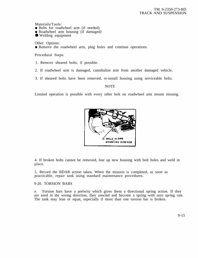
TM 9-2350-273-BDTRACK AND SUSPENSION
Materials/Tools:● Bolts for roadwheel arm (if needed)● Roadwheel arm housing (if damaged)● Welding equipment
Other Options:● Remove the roadwheel arm, plug holes and continue operations.
Procedural Steps:
1. Remove sheared bolts, if possible.
2. If roadwheel arm is damaged, cannibalize arm from another damaged vehicle.
3. If sheared bolts have been removed, re-install housing using serviceable bolts.
NOTE
Limited operation is possible with every other bolt on roadwheel arm mount missing.
4. If broken bolts cannot be removed, line up new housing with bolt holes and weld inplace.
5. Record the BDAR action taken. When the mission is completed, as soon aspracticable, repair tank using standard maintenance procedures.
9-20. TORSION BARS
a. Torsion bars have a pretwist which gives them a directional spring action. If theyare used in the wrong direction, they unwind and become a spring with zero spring rate.The tank may lean or squat, especially if more than one torsion bar is broken.
9-15

TM 9-2350-273-BDTRACK AND SUSPENSION
Procedural Steps (Cont'd)
b. It is most desirable to have torsion bars in positions 1, 2, and 7. Positions 4 and 5are least critical.
c. Torsion tube covers protect the torsion bars from rust and physical scratching ornotching which could shorten the life of the bar. In a combat emergency, the coversare not necessary to the operation of the vehicle.
9-21. SHOCK ABSORBERS
Shock absorbers stabilize the vehicle. The vehicle can function without one or more ofthe shock absorbers but the ride and gun stabilization will be degraded and will getincreasingly worse. The shock absorber depends on the oil with which it is filled forboth, damping and lubrication. The indication of a defective shock absorber will be asignificant loss of oil or feeling cold to the touch.
9-16

TM 9-2350-273-BD
C H A P T E R 1 0
ARMAMENT AND FIRE CONTROL SYSTEM
BDAR FIXES SHALL BE USED 0NLY IN COMBATAT THE DISCRETION OF THE COMMANDER
AND SHALL BE REPAIRED BY STANDARD MAINTENANCE PROCEDURESAS SOON AS PRACTICABLE AFTER THE MISSION IS COMPLETED.
SECTION I. General
10-1. General.
Armament and fire control systems are two classes of equipment. Fire control systems areessentially aids to improve the accuracy and speed of armament firing operations. Allarmament systems provide manual back up devices should the power controlled systems fail.This chapter provides information primarily intended to overcome armament systemfailures. Fire control systems becauseprocedures. Refer to the standard TIM
10-2. Assessment Procedure
of their complexity do not lend themselves to BDARfor fire control repairs.
Damage found to:
-cannon assembly; . . . . . go to para 10-4 thru10-9.
-sighting system; . . . . . . go to specificmaintenance TM
-hull Turret Race; . . . . go to para 10-10-breech assembly; . . . . . go to para 10-6-traversing gear box;. go to normal
maintenance TM-elevation cylinder; . . . . go to specific
maintenance TM-hydraulic system; . . . . go to TM 9-2350
-276-BD

TM 9-2350-273-BDARMAMENT AND FIRE CONTROL SYSTEMS
-gun elevation/ . . . . . . . . . . . . . . . . . . . ..go to specifictraversing system maintenance TMs
-m ain gun power; . . . . . . ... . . . . . . . . . . . go to Para 10-9. .-sighting sytem . . . . . . . . . . . . . . . . . . . go to spcificmaintenance TMs
-Commander’s . . . . . . . . . . . . . . . . . . . . . . go to Para 10-15weapons station;
-coax machine gun . . . . . . . . . . . . . . ..go to specificmaintenance TMs
-turret blower . . . . . . . . . . . . . . . . . . . . . . go to TM 9-2350-system; 276-BD
- System operatesnormally
- System is degraded,however, redundantsystem available
- System is degraded.No redundant system.
- Main gun will notelevate or depress.
- Main gun will nottraverse.
- Main gun incapableof firing.
- Turret damaged beyondrepair.
10-2
TM 9-2350-273-BDARMAMENT AND FIRE CONTROL SYSTEMS
10-3. BDAR Procedure Index. Para
Gun Tube is Unserviceable; Recovery Vehicle Not Available . . . . . . . . . . . . . . . . . . 10-4Bore Evacuator Damaged . . . . . . . . . . . . . . . . . . . . . . ........ ... . . . . . . . . . . . . . . . . . . . . . . . . . . . . . . . . 10-5Breech Block Will Not Close; Closing Spring Broken . . . . . . . ..... . . . . . . . . . . . . . . . . . . . . . 10-6Gun Does Not Fire, Gun Does Not Return To Battery . . . . . . . . . . . . . . . . . . . . . ..... 10-7Gun Will Not Fire; Hard-wire Blasting Machine to Main Gun . . . . . . . . . . . . . . . . . . 10-8Main Gun Inoperative; Electrical Power Loss . . . . . . . ....... . . . . . . . . . .... ....... 10-9Turret Interchangeability . . . . . . . . . . . . . . . . . . . . . . . . .... . . . . . . . . . . . . . . . . . . . . . . . . . . . . . . . . . . . . . . 10-10Gun Mount Interchangeability . . . . . . . . . . . . . . . . . . . . . . . . . . . . . . . . . . . . ...... . . . . . . . . . . . ... . . 10-11Gun Tube Interchangeability . . . . . . . . . . . . . . . . . . . . . . . . . . . . . . . . . . . . . . . . . . . . . . . . . . . . . . . . . . . . . . . . 10-12Turret Power Pack Damage . . . . . . . . . . . . . . . . . . . . . . . . . . . . . . . . . . . . . . . . . . . . . . . . . . . . . . . . . . . . . . . . . 10-13Loader's Safety Switch Failure . . . . . . . . . . . . . . . . . . . . . . . . ... . . . . . ........ . . . . . . . . . .....10-14M85 Gun Inoperative; Power Loss . . . . . . . . . . . . . . . . . . . . . . . . . . . . . . . . . . . . . . . . . . . . . . . . . . ...... 10-15Slipring Defective . . . . . . . . . . . . . ... . . . . . . . . . . . . . . . . . . . . . . . . . . . . . . . . . . . . . . . . . . . . . . . . . . . . . . . . . . ... 10-16Turret Power Pack Interchangeability . . . . . . . . . . . . . . . . . . . . . . . . . . . . . . . . . . . . . . . . . . . . . . . . . . 10-17Manual Pump Fluid Loss . . . . . . . . . ..... . . . . . . . . . . . . . . . . . . . . . . . . . . . . . . . . . . . . . . . . . . . . . . . . . . . . . 10-18Main Accumulator Damaged . . . . . . . . . . . . . . . . . . . . . . . .... . . . . . . . . . . . . . . . . . . ...........10-19
WARNING
Parts of the electrical harness system carries a 300 AMPcurrent potential, which could cause serious accidentalinjuries. Disconnect battery ground terminals when makingconnections.
CAUTION
When arc welding on turret, ground welding equipment to turretonly. When arc welding on hull, ground welding equipment tohull only. Parts of slipring and bearing race can be damagedfrom high currents conducted between hull and turret if weldingequipment is not grounded correctly.
10-3

TM 9-2350-273-BDARMAMENT AND FIRE CONTROL SYSTEMS
SECTION II. Armament BDAR
10-4. GUN TUBE IS UNSERVICEABLE; RECOVERY VEHICLE NOT AVAILABLE
General InformationThis procedure gives instructions for replacing a main gun tube by using another tankrather than a recovery vehicle to hoist the main gun tube.
Limi ta t ion● None
Personnel/Time Required● 3 soldiers● 2 hours
Materials/Tool*● Cargo strap (or rope, or cable) capable of withstanding approximately 2500 pounds.● Sling capable of withstanding approximately 2500 pounds.● An operable (M 1, or M48/M60).● Stiff wire (such as a piece cut from a coat hanger) approximately 7 inches long (or 1-1/2 inch MS90728 screw and two flat washers).● Wood block approximately 2 feet long.● Two guide ropes.● Gun tube wrench (if wrench is not available, it is possible to turn the tube using arope or cargo strap and a tanker bar or 2 x 4 wood board).
Other Options:● Fabricate an A-frame or use a strong tree and vehicle with winch.
Procedural Steps:
CAUTION
The gun tube outer shell can be damaged during handlingoperations if it is not removed.
1. Remove operable tank's front gun tube outer shell if applicable.
2. Remove damaged tank's front and rear gun tubes outer shells, if applicable and boreevacuator.
3. Raise operable tank’s main gun to fully elevated position.
4. Position damaged tank’s main gun slightly below zero degrees elevation.
10-4
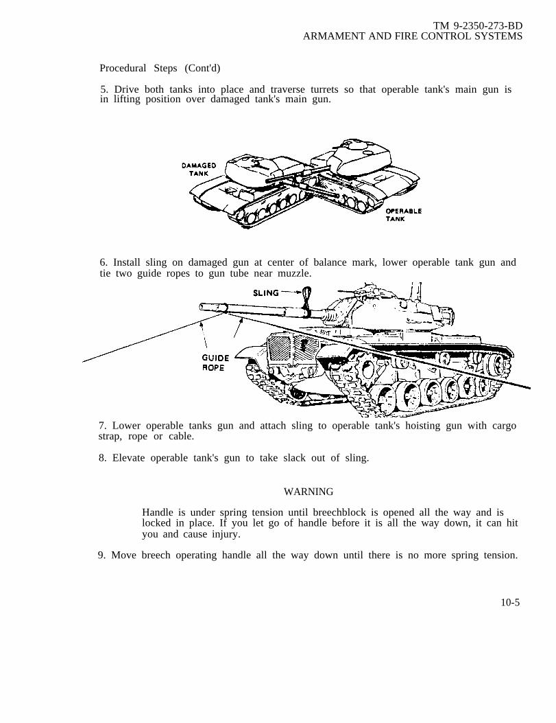
TM 9-2350-273-BDARMAMENT AND FIRE CONTROL SYSTEMS
Procedural Steps (Cont'd)
5. Drive both tanks into place and traverse turrets so that operable tank's main gun isin lifting position over damaged tank's main gun.
6. Install sling on damaged gun at center of balance mark, lower operable tank gun andtie two guide ropes to gun tube near muzzle.
7. Lower operable tanks gun and attach sling to operable tank's hoisting gun with cargostrap, rope or cable.
8. Elevate operable tank's gun to take slack out of sling.
WARNING
Handle is under spring tension until breechblock is opened all the way and islocked in place. If you let go of handle before it is all the way down, it can hityou and cause injury.
9. Move breech operating handle all the way down until there is no more spring tension.
10-5
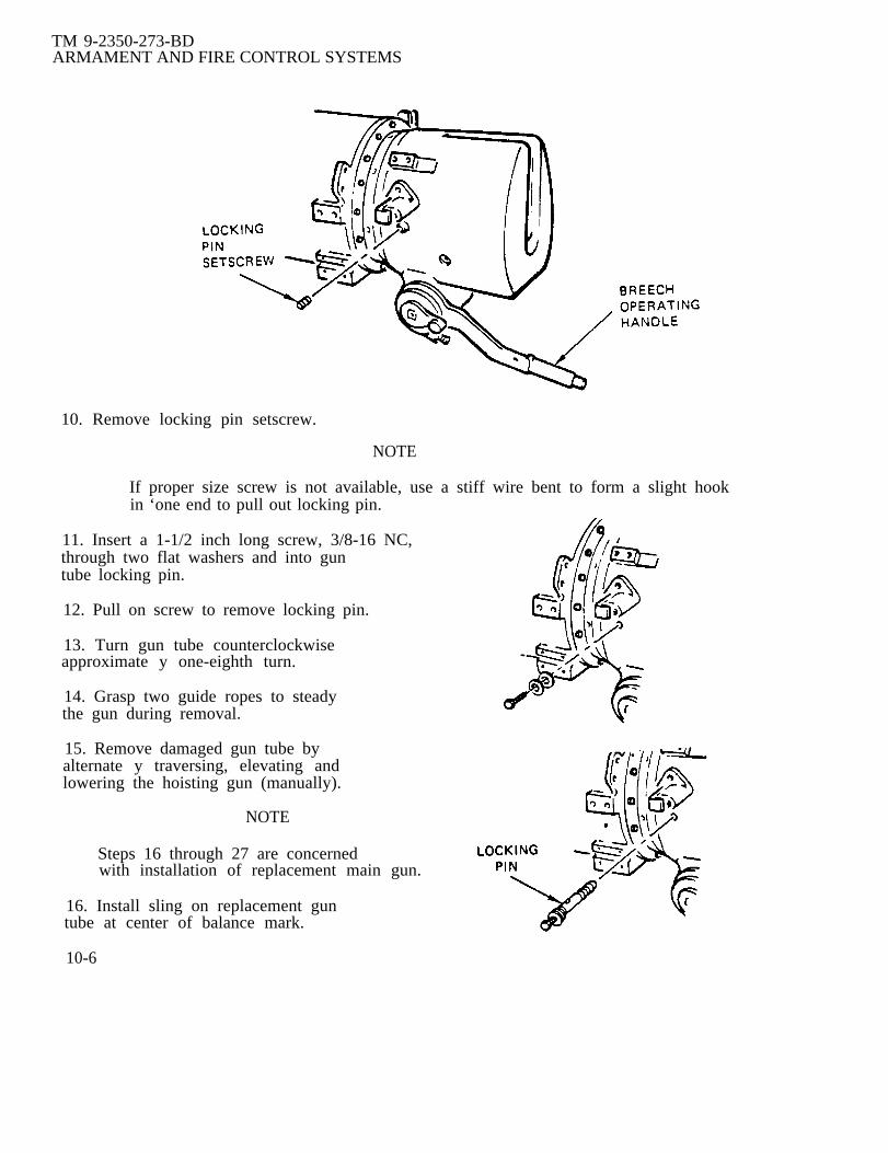
TM 9-2350-273-BDARMAMENT AND FIRE CONTROL SYSTEMS
10. Remove locking pin setscrew.
NOTE
If proper size screw is not available, use a stiff wire bent to form a slight hookin ‘one end to pull out locking pin.
11. Insert a 1-1/2 inch long screw, 3/8-16 NC,through two flat washers and into guntube locking pin.
12. Pull on screw to remove locking pin.
13. Turn gun tube counterclockwiseapproximate y one-eighth turn.
14. Grasp two guide ropes to steadythe gun during removal.
15. Remove damaged gun tube byalternate y traversing, elevating andlowering the hoisting gun (manually).
NOTE
Steps 16 through 27 are concernedwith installation of replacement main gun.
16. Install sling on replacement guntube at center of balance mark.
10-6

TM 9-2350-273-BDARMAMENT AND FIRE CONTROL SYSTEMS
Procedural Steps (Cont'd)
17. Tie two guide ropes to replacement gun tube near muzzle.
18. Attach sling to hoisting gun with cargo strap, rope, or cable.
19. Elevate hoisting gun to take slack out of sling.
20. Grasp two guide ropes to steady the gun during installation.
21. Install replacement gun tube in tank by alternate y traversing, elevating andlowering the hoisting gun (manually).
22. Turn gun tube clockwise approximately one-eighth turn.
23. Install locking pin in breech and secure with locking pin setscrew.
24. Remove sling and cargo strap from gun tubes.
25. Install hoisting tank's front gun tube (outer shell).
26. Install replacement gun's front and rear gun tubes (outer shells) and bore evacuatorchamber.
27. Record the BDAR action taken. When the mission is completed, as soon aspracticable, repair tank using standard maintenance procedures.
10-5. BORE EVACUATOR DAMAGED
General InformationAs a round is propelled through the gun tube, gas pressure is forced inside the boreevacuator. As the round leaves the tube, bore evacuator pressure rushes out behind theround, exhausting excessive smoke and fumes. If the evacuator is damaged or leaks,this pressure is lost, causing excessive smoke and fumes to enter the turret as thebreech block opens. This procedure repairs puncture damage to the bore evacuator.Smoke fumes limit the crews capabilities to operate inside the turret.
Limitations:● None
Personnel/Time Required:● 1 soldier● 1 hour
Materials/Tools:● Welding equipment● Sheet metal, l/4-inch thick (size dependent on damage)
10-7
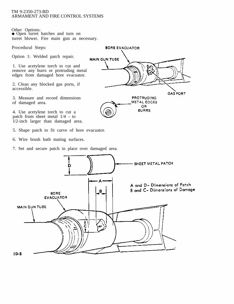
10-8
TM 9-2350-273-BDARMAMENT AND FIRE CONTROL SYSTEMS
Other Options:● Open turret hatches and turn onturret blower. Fire main gun as necessary.
Procedural Steps:
Option 1: Welded patch repair.
1. Use acetylene torch to cut andremove any burrs or protruding metaledges from damaged bore evacuator.
2. Clean any blocked gas ports, ifaccessible.
3. Measure and record dimensionsof damaged area.
4. Use acetylene torch to cut apatch from sheet metal 1/4 - tol/2-inch larger than damaged area.
5. Shape patch to fit curve of bore evacuator.
6. Wire brush bath mating surfaces.
7. Set and secure patch in place over damaged area.

TM 9-2350-273-BDARMAMENT AND FIRE CONTROL SYSTEMS
Procedural Steps (Cont'd)
CAUTION
When arc welding on turret, ground welding equipment to turret only. Parts ofslip ring and race bearings can be damaged from high currents conductedbetween hull and turret if welding equipment is not grounded correctly.
CAUTION
Disconnect electrical connectors from laser rangefinder before arc weldinganywhere on tank. Rangefinder can be damaged by electrical current causedduring arc welding.
8. Use gas or arc to weld a continuous bead around the patch. Check weld for cracksor openings, and repair if necessary.
Option 2: Fabricated clamp repair.
Limitations:● NonePersonnel/Time Required:● 1 soldier● 1 hour
Materials/Tools:● Acetylene torch● Asbestos paper or other suitable fire resistant material● Grinder● Hexagon head nuts, 3/8-inch (as required)● Lockwashers (as required)● Machine screws, 3/8-inch x l-inch (as required)● Sheet metal, l/4-inch thick, about 21-inches long and wide enough to overlapdamage.
Procedural Steps:
1. Use acetylene torch and grinder to cut and remove any burrs or protruding metaledges that may affect air-tight seal.
2. Clean any blocked gas ports, if accessible.
3. Measure and record dimensions of damaged area.
10-9

10-10
TM 9-2350-273-BDARMAMENT FIRE AND CONTROL SYSTEMS
Procedural Step (Cont'd)
If damage is extensive,ensure a proper seal.
NOTE
clamp should be made same width as bore evacuator to
4. Use acetylene torch to cut two 10-1/2 inch long metal strips at least l-inch widerthan damaged area.
TM 9-2350-273-BDARMAMENT AND FIRE CONTROL SYSTEMS
Procedural Steps (Cont'd)
5. Shape each metal band to fit curve of bore evacuator. When metal bands are placedaround bore evacuator, a gap between 1/8 to l/4-inch should exist between halves (seeillustration).
6. Remove bands from bore evacuator and line inside surface of each band withasbestos paper or some other suitable fire resistant material.
7. Drill 3/8-inch evenly spaced holes in each end of both bands (see illustration).
8. Set bands in place over damaged area.
9. Secure bands against bore evacuator with screws, nuts, and lockwashers.
Record the BDAR action taken. When the mission is completed, as soon as practicable,repair tank using standard maintenance procedures.
10-6. BREECH BLOCK WILL NOT CLOSE, CLOSING SPRING BROKEN
General InformationIf the breech-closing mechanism fails to function as a result of broken leaf springs,function can be restored by repositioning broken spring leafs.
Limitations:● Increased stress on remaining unbroken springs.
Personnel/Time Required:● 1 soldier● 15-20 minutes
Materials/Tools:● Replacement leaf springs
Other Options● Use replacement leaf springs or entireleaf spring assembly from an M1 tank.
Procedural Steps:
1. Remove breech closing mechanismfrom breech spring assembly.
10-11

TM 9-2350-273-BDARMAMENT AND FIRE CONTROL SYSTEMS
Procedural Steps (Cont):
2. Remove leaf spring assembly from closingmechanism assembly by driving the retainingpins from each end.
3. Reassemble springs, placing as manyunbroken springs as possible betweenbroken springs.
4. Install leaf spring assembly andretaining pins in breech closing mechanism.
5. Install breech closing mechanism inbreech spring assembly.
6. Adjust spring tension by turningspring tension adjuster toward breechend of main gun with spanner wrenchuntil click is heard.
7. Record the BDAR action taken.When the mission is completed, asas practicable, repair tank usingstandard maintenance procedures.
10-7. GUN DOES NOT FIRE; GUN DOES NOT RETURN TO “BATTERY”
General Information:If the main gun does not return to “battery” after firing, the firing circuit will be opencausing a failure to fire from any trigger, switch, or position.
Limitations:
Personnel/Time Required:● 2 soldier● 4-10 minutes
10-12

Materials/Tools:● Rex. cable. or
TM 9-2350-273-BDARMAMENT AND FIRE CONTROL SYSTEMS
strap approximately 40 feet long.● Wood block (2" x 4"- 12 inches long).
WARNING
Do not circumvent the safety features when the main gun is ‘lout-of-battery”.Causing the main gun to fire when “out-of-battery" could result in equipmentdamage and injury to personnel.
Procedural Steps:
1. Traverse turret so main gun is forward over driver’s compartment.
2. Lock turret.
CAUTION
Do not force gun ‘tout-of-battery” more than 12 inches.
3. Select a tree orobstacle.
4. Drive tank very
Components may be damaged.
another tank and drive to a point where main gun tube just touches
slowly forward to force main gun “out-of-battery” 4 to 6 inches.
5. Reverse tank and quickly back tank away from obstacle.
6. If main gun returns to “battery” position, continue mission. If not, do steps 7through 11.
7. Guide rope down bore of main gun and out through breech as shown on the next page.
8.
9.
10.
Inside turret, tie rope to 2 x 4.Place 2 x 4 against breech of maingun.
Outside tank, tie rope to solid objectsuch as a tank or tree.
Very slowly back-up tank until maingun moves to “in-battery” position.
10-13
TM 9-2350-273-BDARMAMENT AND FIRE CONTROL SYSTEMS
Procedural Steps (Cont'd)
CAUTION
Cease firing if length of recoil is excessive or if recoil actionis irregular.
11. Clear bore of main gun.
12. Repeat the recoil exercise (steps 1 through 6).
WARNING
If the gun does not return to battery, do not fire the weapon.The weapon will be destroyed causing equipment damageand personnel injuries or cleat h.
13. Record the BDAR action taken. When the mission is completed, as soon aspracticable, repair tank using standard maintenance procedures.
10-8. GUN WILL NOT FIRE; HARD-WIRE BLASTING MACHINE TO MAIN GUN
General Information:If all other methods to fire the main gun fail, the blasting machine can be wireddirectly to the main gun primer to fire the main gun.
Limitations:● Safety circuits are bypassed
Personnel/Time Required:● 1 soldier● 15 minutes
Material/Tools:● Knife● Tape
Other Options:● Use magneto-type field-phone● Refer to para. 10-9, main gun inoperative; electrical power loss procedure
Procedural Steps:
1. Cut connector off blasting machine cable.
2. Remove cable from cable clamps.
10-14

ARMAMENTTM 9-2350-273-BD
AND FIRE CONTROL SYSTEMS
3.
4.
5.
6.
7.
8.
Strip approximately one inch of insulation from white and blue wires.
Secure white wire to terminal E 1 on main gun primer.
Secure blue wire to terminal E2 on main gun primer.
Bend other wires out of the way and tape (to insulate) the other wire ends.
Crank blasting machine handle two to four times to fire main gun.
Record the BDAR action taken. When the mission is completed. as soon aspracticable, repair the vehicle using standard maintenance procedures.
10-9. MAIN GUN INOPERATIVE; ELECTRICAL POWER LOSS
General InformationMain gun will not fire from any switch or position. Magneto from telephone set or fieldtelephone produces enough voltage to fire gun manually.
Limitations● Only commander or gunner can fire the main gun.
Personnel/Time Required:● 1 soldier● 20-30 minutes 10-15

TM 9-2350-273-BDARMAMENT AND FIRE CONTROL SYSTEMS
Materials/Tools:● TA- 1/PT telephone set● TA-312/PT field telephone● wire strippers or knife
Other Options:● Hard wire blasting machine to gun.
Procedural Steps:
1.
2.
3.
4.
Remove wires from blasting machine.
Strip wires back one-half inch.
Connect wires to field telephone in place of blasting machine.
Use hand crank on field telephone to generate voltage needed to fire main gun. Donot touch the wires when cranking the telephone set.
5. Record the BDAR action taken. When the mission is completed, as soon aspracticable, repair tank using standard maintenance procedures.
10-10. TURRET INTERCHANGEABILITY
General Information:Turret is damaged beyond repair. Turrets can be exchanged from one system’s chassisto another with modifications.
Limitations:● NBC equipment might not be operational.
Personnel/Time Required:● 3 soldiers● 10-18 hours
Materials/Tool:●
●
●
●
●
●
Replacement turretCutting torch or sawM88A1 VTR or 20-ton crane`Turret standSlip ring shim or similar materialDrill
10-16

TM 9-2350-273-BDARMAMENT AND FIRE CONTROL SYSTEMS
Procedural Steps:
1. Remove damaged turret.
2. To install M48A5 turret on M60 series tank chassis: (See table 10-1 forinterchangeability.)
a. Modify M48A5 turret platform to accept M60 series tank slip ring.
(1) Use cutting torch or saw to cut M48A5 platform slip ring hole to the size ofM60 series tank platform slip ring hole.
(2) Use new or used slip ring shims or similar material to raise slip ring highenough (approximately one-half to two inches) to accept the shorter M48A5 turret.
b. Install turret and connect all connections.
3. To install M60 series turret on M48A5 chassis: (See table 10-1 forinterchangeability.)
a. Change platform legs. Use shorter legs from damaged M48A5 turret on the M60series turret.
b. After short legs are installed, adjust turret power pack to correct height orredrill mounting brackets for new position.
c. Install turret on chassis.
d. Make all connections.
4. Check all fluid connections for leakage and electrical connections for properoperation.
INTERCHANGEABILITY TABLE 10-1
TURRET CHASSIS CHASSIS CHASSISM48A5 M60A1 M60A3
M48A5 No rework Step 2 Step 2
1M60A1 Step 3 No rework No rework
M60A3 Step 3 No rework No rework
5. Record BDAR action taken. When mission is completed, as soon as practicable,repair tank using standard maintenance procedures.
10-17

TM 9-2350-273-BDARMAMENT AND FIRE CONTROL SYSTEMS
10-11. GUN MOUNT INTERCHANGEABILITY
General InformationGun mount is damaged. The M68 gun mounts are interchangeable on the M48A5,M60A1, and British L7A1 tanks.
Limitations:● None
Personnel/Time Required:● 3 soldiers● 4 hours
Materials/Tools:● Lift capability● Replacement gun mount● 2 point sling● Chain hoist
Procedural Steps:
1. Obtain a gun mount from another vehicle.
2. Attach boom from wrecker to gun mount and attach chain hoist as shown.l0-18
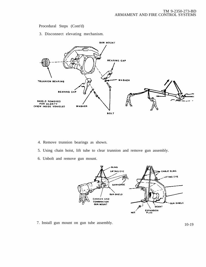
TM 9-2350-273-BDARMAMENT AND FIRE CONTROL SYSTEMS
Procedural Steps (Cont'd)
3. Disconnect elevating mechanism.
4. Remove trunnion bearings as shown.
5. Using chain hoist, lift tube to clear trunnion and remove gun assembly.
6. Unbolt and remove gun mount.
7. Install gun mount on gun tube assembly. 10-19

TM 9-2350-273-BDARMAMENT AND FIRE CONTROL SYSTEMS
Procedural Steps (Cont'd)
8. Using boom, lift gun mount and tube assembly and re-install into turret.
9. Re-install trunnion bearings.
10. Reconnect elevating mechanism.
11. Record the BDAR action taken. When the mission is completed, as soon aspracticable, repair tank using standard maintenance procedures.
10-12. GUN TUBE INTERCHANGEABILITY
General Information:Gun tube is damaged and requires replacement. The 105MM gun tubes areinterchangeable on the M48A5, M60A1, M60A3,M1, the British L7A1 and the GermanL7A3 Tanks.
Limitations:● None
Personnel/Time Required:● 2 soldiers● 1-2 hours
Materials/Tools:● Lift capability
Procedural Steps:
1. Remove heat shields, if applicable.
2. Attach block and tackle or boomfrom wrecker, to bottom of tube.
3. Remove pin holding gun tube in place.
4. Using girth wrench, turn gun tubeone-eight turn counterclockwise or tounlock-position mark on shield.
5. Attach guide ropes to end of
6. Remove tube assembly.
tube.
7. Insert replacement gun tube intoshield assembly.
10-20

TM 9-2350-273-BDARMAMENT AND FIRE CONTROL SYSTEMS
Procedural Steps (Cont'd)
8. Using girth wrench, turn tubeclockwise one-eight turn or to lockposition mark on shield.
9. Replace holding pin.
10. Reinstall heat shields.
11. Record BDAR action taken. When the mission is completed, as soon as practicable,repair tank using standard maintenance procedures.
10-13. TURRET POWER PACK DAMAGE
General InformationA hole can be cut in the turret floor to reduce the time required (normally 4 hours) toreplace a damaged or inoperative turret power pack.
Limitations:● None
Personnel/Time Required:● 2 soldiers● 1 hour
Materials/Tools:● Acetylene torch● Wood blocks● Replacement motor
Procedural Steps:
1. Traverse the turret so that the power pack is not over the battery compartment.
WARNING
Ensure area to be cut is free of grease, oil and hydraulic fluid byflushing with water. Hydraulic fluid is extremely flammable and maycause serious injury to personnel if ignited.
2. Using a torch cut a hole in the turret floor slightly larger than the power packmotor, directly below power pack.
3. Replace damaged or failed motor by using the following procedures:
a. Turn turret to driver’s access. This is the only position where the motor canbe removed.
b. Place wood blocks under motor to support it. 10-21
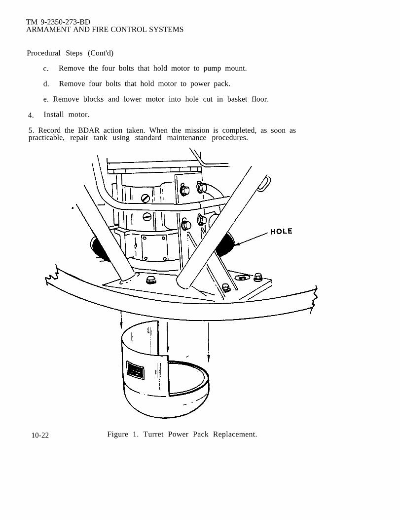
TM 9-2350-273-BDARMAMENT AND FIRE CONTROL SYSTEMS
Procedural Steps (Cont'd)
c. Remove the four bolts that hold motor to pump mount.
d. Remove four bolts that hold motor to power pack.
e. Remove blocks and lower motor into hole cut in basket floor.
4. Install motor.
5. Record the BDAR action taken. When the mission is completed, as soon aspracticable, repair tank using standard maintenance procedures.
10-22 Figure 1. Turret Power Pack Replacement.

TM 9-2350-273-BDARMAMENT AND FIRE CONTROL SYSTEMS
10-14. LOADER’S SAFETY SWITCH FAILURE
General Information:Gun will not fire by any switch or the blasting machine. The loader’s safety switch canbe by passed using this procedure.
Limitations:● No safety device.
Personnel/Time Required:● 1 soldier● 30-60 minutes
Materials/Tools:● Wire cutters● Wire stripper or knife
Procedural Steps:
WARNING
The loader's safety system is disabled.held together during each firing. Takenot touch each other, or contact metaltimes.
The wires have tocare that they doobjects at all other
1. Identify and cut circuits 113B and 113C between safety switch and harnessconnectors as shown. Make sure the lengths of the two wires are different, soof the dangling wires will not accidently touch each other.
the ends
NOTEBe careful not to cut circuit 113G, which is the groundwire for the blasting machine. If circuit 113G is cut,the blasting machine is disconnected from the firing circuit.
2. Strip 1/2 inch of the insulation from the harness side of circuits 113B and 113C. Toactivate the firing circuit, manually touch the ends of these two wires together.
10-23

TM 9-2350-273-BDARMAMENT AND FIRE CONTROL SYSTEMS
Procedural Steps (Cont'd)
3. Record the BDAR action taken. When the mission is completed, as soon aspracticable, repair tank using standard maintenance procedures.
10-15. M85 GUN INOPERATIVE; POWER LOSS
General InformationM85 machine gun will not fire due to loss of electrical power. A simple procedure willrestore the firing circuit.
Limitations:● None
Personnel/Time Required:● 1 soldier● 15 minutes
Material/Tools:● Wire● Wire strippers, or knife
Other Options:● Fire weapon manually.
Procedural Steps:
WARNING
Ensure M85 machine gun is clearof ammo before attempting fix.Failure to do so could result ininadvertent firing of gun, resultingin injury or death to personnel.
1. Cut and strip wire goingto the M85 trigger control.
2. Cut and strip wire from thehot side of the nearest working domelight.
3. Connect a wire from the dome lightto M85 trigger control.
5. Record the BDAR action taken.When the mission is completed, as soonas practicable, repair tank usingstandard maintenance procedures.10-24

TM 9-2350-273-BDARMAMENT AND FIRE CONTROL SYSTEMS
10-16. SLIPRING DEFECTIVE
General Information:The slipring is the connecting link for transferring electrical power from the hull to theturret. This procedure gives an expedient to transmit the electrical power past adefective slipring.
Limitation:Traversing is limited.
Personnel/Time:● 2 soldiers● 4 hours
Material/Tools:● Tape● Soldering iron● Multimeter or expedient continuity tester.● Twine or cord● Solder, rosin-core
Other Options:● Replace defective slipring
Assessment Steps:
1. Turn MASTER switch off.
2. Manually traverse the turret to gain access to the battery compartment.
3. Remove slipring cover.
4. Disconnect hull power harnessfrom the slipring.
10-25

TM 9-2350-273-BDARMAMENT AND FIRE CONTROL SYSTEMS
Assessment Steps (Cont'd)
5. Turn MASTER switch to ON.
6. Check for 24 vDC at hull power harness connector.
7. Turn MASTER switch to OFF.
8. Disconnect turret power harness.
10-26
TM 9-2350-273-BDARMAMENT AND FIRE CONTROL SYSTEMS
Assessment Steps (Cont'd)
9. Connect hull power harness to slipring.
10. Turn MASTER switch to ON.
11. Check for power at slipring turret connector.
a. If power is present, go to topic” TURRET NO HYDRAULIC POWER”, refer topara 6-10.
b. If no power is present, go to step 12.
12. Bypass slipring by using battery ground cable.
13. Turn MASTER switch to OFF.
Procedural Steps
1. Remove one battery ground cable and remove terminal lugs from each end.
2. Disconnect hull power harness from slipring.
3. If terminals required to fit hull and turret power harness connectors are available,solder to each end of the battery ground cable if terminals are not available, stripapproximately one inch of insulation from each end and tin with solder.
4. Connect battery cable to hull and turret power harness connectors.
5. Reinforce connections using cord, twine, or tape.
6. Record the BDAR action taken. When the mission is completed, as soon aspracticable, repair the vehicle using standard maintenance procedures.
10-27

TM 9-2350-273-BDARMAMENT AND FIRE CONTROL SYSTEMS
10-17. TURRET POWER PACK INTERCHANGEABILITY
General Information:Power pack damaged beyond repair. Power packs from the M109, Ml 10, Ml and M48series vehicles are interchangeable. Reservoirs and motors may vary in size andcapability, but they will function.
Limitations:● None
Personnel/Time Required:● 1 soldier● 1 hour
Materials/Tool:● Power pack● Hydraulic fluid
Procedural Steps:
1. Disconnect electrical connections.
2. Disconnect all hydraulic lines and plug them.
3. Unbolt and remove power pack.
4. Clean the mounting surfaces carefully.
5. Install new or used power pack.
6. Reconnect electrical connections.
7. Reconnect all hydraulic lines.
8. Replace any lost hydraulic fluid.
9. Perform operational check and inspect for fluid leaks.
10. Record BDAR action taken. When the mission is completed, as soon as practicable,repair tank using standard maintenance procedures.
10-28
TM 9-2350-273-BDARMAMENT’ AND FIRE CONTROL SYSTEMS
10-18. MANUAL PUMP FLUID LOSS
General Information:Hydraulic system damaged, manual pump will not operate without fluid.
Limitations:● Frequent checks for leaks● Degraded turret operations
Personnel/Time Required:● 1-2 soldiers● 1 hour
Materials/Tools:● Two large cans● Hydraulic fluid, or oil
Other Options:● See TM 9-2350-276-BD,Hydraulics.
Procedural Steps:
1. Disconnect hydraulic lines atpowerpack going to manual pump.
2. Cut tops out of cans, orpunch large holes into tops of cans.
3. Bend lines carefully so thatthey will hang into cans.
4. Fill input can with fluid,it will act as a reservoir,so the pump will operate.
5. When manual pump is operatedthe second can will catch fluidso it can be returned to input can.
6. Record the BDAR action taken. When the mission is completed, as soon aspracticable, repair tank using standard maintenance procedures.
10-29

TM 9-2350-273-BDARMAMENT AND FIRE CONTROL SYSTEMS
10-19 MAIN ACCUMULATOR DAMAGED
a The hydraulic system used for gun operation can be operated in a degradedmode if the hydraulic lines are plugged or isolated on the system side of theaccumulator. Operation will be eratic without the buffer action provided by theaccumulator pressure.
b. The accumulator may also be replaced with an accumulator from an Ml tankor other M48/M60 series tank. The brake system accumulator from the Ml tank mayalso be used but the capacity is lower.
l0-30

TM 9-2350-273-BD
CHAPTER 11
COMMUNICATION SYSTEMS
BDAR FIXES SHALL BE USED ONLY IN COMBATAT THE DISCRETION OF THE COMMANDER
AND SHALL BE REPAIRED BY STANDARD MAINTENANCE PROCEDURESAS SOON AS PRACTICABLE AFTER THE MISSION IS COMPLETED.
SECTION I. General
11-1. Scope.
This chapter contains the fault assessment and expedient repair proceduresneeded to locate and fix battlefield damage to the vehicle’s communications system.
11-2. General.
The procedures in this chapter are used to repair battlefield damage to theAN/VIC-1 intercommunications set, the radio systems, the KY-57 (KY-38) speechsecurity system and all associated wiring and cables.
11-3. Functional Details.
a. The AN/VIC-l intercom set consists of the AM-1780 amplifier, four C-2298 orC-10456 control boxes, one C-2742 remote switching control box, four CVC helmets andall associated wiring and cables. The AN/VIC-1 allows voice intercom to take placebetween the vehicle commander and all crew members.
b. Three basic configurations of radio systems are installed in most trackedvehicles. All three radio systems supply non-secure frequency modulation (FM) voiceradio capabilities through the AN/VIC-1 intercom set to the tank commander and allcrew members. All three radio systems utilize the MT- 1029 mount for the basicreceiver-transmitter and the MT- 1898 mount for the auxiliary receiver. The MX-6707matching unit is used in conjunction with all receiver-transmitters and the AB-558 mastbase is used in conjunction with the auxiliary receivers. The AS- 1729 antenna system isused with all receiver-transmitters and either the MS-116A, MS-117A, and the MS-118Aantenna elements or the AT-1095 antenna element is used with the auxiliary receivers.All associated wiring and cables are the same for each system.
(1) The AN/VRC-12 consists of a RT-246 receiver-transmitter with 10 presetchannels which can be automatically switched and tuned by means of the C-2742remote switching control box and a R-442 auxiliary receiver.
11-1

TM 9-2350-273-BDCOMMUNICATIONS SYSTEM
(2) The AN/VRC-47 consists of a RT-524 receiver-transmitter and R-442auxiliary receiver.
(3) The AN/VRC-64 consists of a RT-841 receiver-transmitter, an AM-2060amplifier and a R-442 auxiliary receiver.
c . The two current speech secur i ty sys tems provide for secure voicecommunications when used in conjunction with any of the receiver-transmittersmentioned above.
(1) The Vinson speech security system consists of a J-3513 interconnection box,335-14 distribution box, KY-57 speech security device, MT-4626 mount and allassociated wiring and cables.
(2) The Nestor speech security system consists of a 3-2731 distribution box, 3-3024interconnection box, KY-38 speech security device, MT-3823 mount, AM-4979 amplifierand all associated wiring and cables.
11-2

TM 9-2350-273-BDCOMMUNICATIONS SYSTEM
SECTION II. General Operating Procedures
11-4. General
This section contains general operating procedures for the AN/VRC-12 seriesradios (AN/VRC-12, AN/VRC-47 and AN/VRC-64) when used in conjunction with theAN/VIC-1 intercommunications set. TM 11-5830-340-12 lists operating procedures forthe system, but for convenience, the main points have been reproduced here.
a . Normal Radio Operation with AN/VIC-l Intercommunications Set.
(1) Turn turret power on. Turn MAIN PWR on the AM-1780 to NORM.This position makes power available to the radio and the aux receiver connected to theAM-1780. See figure 11-1.
(2) Turn POWER switch on the radio (connected to 3501) to either HIGH orLOW. This supplies power to the AM-1780.
(3) Turn POWER CKT BKR switch on the AM-1780 to ON. This suppliespower to the AM- 1780 and to all control boxes connected to the AM- 1780.
(4) Turn INSTALLATION SWITCH on the AM-1780 to OTHER position.This is the normal position which allows the radio accessories connected to the controlboxes to operate both the radio and the intercom equipment.
(5) Use the RADIO TRANS switch on the AM-1780 to select crew membersallowed to transmit with the radio.
CDR and CREW - if all crew members are allowed to transmit.CDR ONLY - if only the crew commander is allowed to transmit.LISTENING SILENCE - if no one is allowed to transmit.
(6) Select the desired loudness of the intercom and radio signals with theINT ACCENT switch on the AM-1780,
OFF position - both signals have the same loudness.ON position -the loudness of the radio signals is reduced below the level ofthe intercom signals.
(7) TO turn off the AM-1780 and radio equipment, turn the MAIN PWRswitch on the AM- 1780 and the POWER switch on the radio to OFF.
b. Normal Intercom Operation with the AN/VIC-1 Intercommunications Setwithout radios.
1 1 3

TM 9-2350-273-BDCOMMUNICATIONS SYSTEM
(1) Turn turret power on. Turn MAIN PWR switch on the AM-1780 to INTONLY. Power is now available for only intercom equipment. See figure 11-1.
(2) Turn POWER CKT BKR switch on the AM-1780 to ON. This suppliespower to AM-1780 and all control boxes connected to the AM- 1780.
NOTE
Do not place INSTALLATION switch in the INTONLY position when the AM-1780 is connectedto a radio system.
(3) Turn INSTALLATION SWITCH on the AM-1780 to OTHER.
(4) “INTERCOM ONLY” operation is now possible using the control boxes andthe audio accessories connected to them.
(5) To turn off the AM-1780, place the MAIN PWR and POWER CKT BKRswitches to OFF.
Figure 11-1. AM-1780 Amplifier
11-4
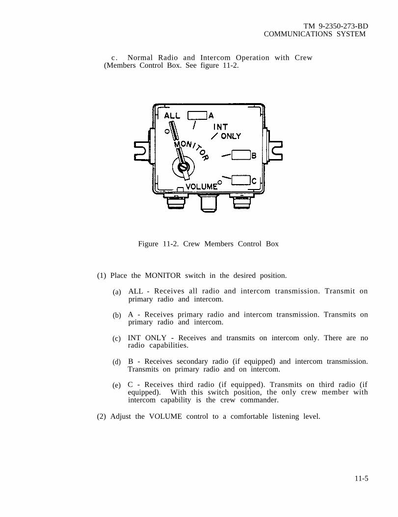
TM 9-2350-273-BDCOMMUNICATIONS SYSTEM
c. Normal Radio and Intercom Operation with Crew(Members Control Box. See figure 11-2.
Figure 11-2. Crew Members Control Box
(1) Place the MONITOR switch in the desired position.
(a)
(b)
(c)
(d)
(e)
ALL - Receives all radio and intercom transmission. Transmit onprimary radio and intercom.
A - Receives primary radio and intercom transmission. Transmits onprimary radio and intercom.
INT ONLY - Receives and transmits on intercom only. There are noradio capabilities.
B - Receives secondary radio (if equipped) and intercom transmission.Transmits on primary radio and on intercom.
C - Receives third radio (if equipped). Transmits on third radio (ifequipped). With this switch position, the only crew member withintercom capability is the crew commander.
(2) Adjust the VOLUME control to a comfortable listening level.
11-5

TM 9-2350-273-BDCOMMUNICATIONS SYSTEM
SECTION III. Fault Assessment Tables and Procedures
11-5. Fault Assessment Procedures.
a. Be sure to read Chapter 2 before starting troubleshooting. The appearance ofan assembly or component may indicate its general condition and reflect the type ofdamage it has suffered. Examine for dented surfaces or holes, torn insulation, severedcables, or other evidence of damage. This might indicate the source of trouble and theneed for repairs. Also check component boxes for unusual odors. After obvious damagehas been repaired, attempt to operate the communications system to check for damagethat might not be so obvious. Procedures below direct you to a detailed assessmentprocedure. The detailed assessment procedure leads to an expedient repair procedure,if one exists, for the particular battlefield damage or to another chapter in this manual.
b. Intercommunications Set Assessment.
Damage:
-AM 1780 Inoperative . . . . . . . . . . . . . . . . . go to para 11-6
C-2298 or C-10456 . . . . . . . . . . . . . . . . . . . . . . go to para 11-7Inoperative
Damage:
-Radio Inoperative . . . . . . . . . . . . . . . . . . . . . . go to para 11-8(No Power)
-Radio does not receive . . . . . . . . . . . . . . . go to para 11-9
-Radio does not transmit . . . . . . . . . . . . . go to para 11-10
-Radio Inop. in “New Squelch” pos go to para 11-11
-Aux Receiver Inoperative . . . . . . . . . . . go to para 11-12
Damage:
-System Inoperative (No Power) . . . go to para 11-13
-System Inoperative . . . . . . . . . . . . . . . . . . . . go to para 11-1411-6

11-6. OBSERVABLECONTROL BOX
TM 9-2350-273-BDCOMMUNICATIONS SYSTEM
SYMPTOM: THE INTERCOM DOES NOT WORK ON ANY
Detailed Assessment Steps:
1. Make sure the DC power is available to the turret by checking the dome light orother electrical equipment in the turret.
2. Make sure the MK-2096 Mini-Transient Voltage Suppressor is operational bychecking for a red light on the suppressor. If the light is lit, replace or remove thesuppressor.
3. Make sure that the MX-7777 or MX-7778 Transient Voltage Suppressor isoperational by depressing the Battle-Override switch. If the suppressor is bad, replaceor repair as necessary.
4. Check that communication equipment is turned on and the switches are in theproper positions. (Refer to para. 11-4.)
5. Check that cables are connected to the proper connectors, correctly aligned, andtightly connected to the receptacles.
6. Jiggle the cables to check for intermittent opens or shorts.
a. If a defective cable is found, follow the procedures listed below:
(1) Replace the defective cable in accordance with standard repairprocedures.
(2) Replace the defective cable with an acceptable replacement cablerefer to para 11-34.
(3) Repair the defective cable in accordance with the repair proceduresin para. 11-30 or TM-9-2350-276-BD.
b. If a defective cable is not found, then follow theprocedures in TM 11-5820-401-12.
troubleshooting
11-7. OBSERVABLE SYMPTOM: THE INTERCOM WORKS ON SOME CONTROLBOXES BUT NOT ALL
Detailed Assessment Steps:
1.
2.and
Repeat steps 4 thru 6 in para. 11-6.
Replace CVC helmet and connectingconnecting cable.
cable with a known operational CVC helmet
11-7
TM 9-2350-273-BDCOMMUNICATIONS SYSTEM
Detailed Assessment Steps (Cont'd)
a. If the problem no longer exists, replace the defective CVC helmet orconnecting cable.
b. If the problem has not been corrected, go to step 3.
3. Disconnect CX-4723 cable leading to the non-operational control box at the AM-1780, and switch it with another CX-4723 cable at the AM-1780 receptacles.
If the same problem occurs in the control box now connected to thatreceptacle, repair or replace the AM-1780.
b. If the problem stays with the same control box, go to step 4.
4. Switch the CX-4723 cables back to their original positions on the AM-1780, andreplace the non-operational control box with a known operational control box.
a. If the problem no longer exists, replace or repair the control box.
b. If the problem still exists, replace or repair the CX-4723 cable between thecontrol box and the AM- 1780.
5. If the cable and/or the control box cannot be repaired or replaced, install the fieldexpedient intercom described in para. 11-22.
11-8. OBSERVABLE SYMPTOM: RADIO AND/OR INTERCOM ARE NOT WORKINGPROPERLY
Detailed Assessment Steps:
1. If the radio is working properly but the intercom is not working properly, refer topara. 11-6 and/or 11-8.
2. Make sure the control settings on the AM- 1780 are correct.
3. Make sure the switches on all control boxes are set to ALL.
4. Set all switches on all CVC helmets to the LISTEN or center position.
5* Check CVC helmets and connecting cables in turn by substituting a knownoperational CVC helmet and connecting cable at each control box.
a. If the problem no longer exists, replace or repair the CVC helmet orconnecting cable using standard maintenance procedures.
b. If the problem still exists, go to step 6.
11-8

TM 9-2350-273-BDCOMMUNICATIONS SYSTEM
Detailed Assessment Steps (Cont’d)
6. Make sure the radio is firmly seated in the mount by loosening the mount to radioclamps. Move the radio forward. Line up the guide pins and slide the radio firmly backinto the mount. Tighten the clamps.
a. If the problem no longer exists, no further actions are necessary.
b. If the problem still, exists go to step 7.
7. Replace radio with a known operational radio.
a. If the problem no longer exists repair the radio using standard maintenanceprocedures.
b. If the problem still exists, go to step 8.
8. Make sure all cables are connected properly.
a. If a defective cable is found follow the procedures listed below:
(1) Replace the defective cable in accordance with standard repairprocedures.
(2) Replace the defective cable with an acceptable replacement cable listedin para 11-34.
(3) Repair the cable in accordance with the procedures in para. 11-30 or theelectrical chapter of TM 9-2350-276-BD.
b. If a defective cable is not found, follow the troubleshooting procedures in TM 11-5820-401-12.
11-9. OBSERVABLE SYMPTOM: THE RADIO DOES NOT RECEIVE THE STATION
Detailed Assessment Steps:
1. Check that all switch settings are as described in para. 11-4.
a. If the problem still exists, refer to para. 11-7 to check for possible intercomproblems.
b. If the blower motor does not run or the above procedures do not isolate thefault, go to step 2.
2. Make sure the radio is firmly seated in the mount by loosening the clamps. Movethe radio forward. Line up the guide pins and slide the radio firmly back into themount. Tighten the clamps.
11-9

TM 9-2350-273-BDCOMMUNICATIONS SYSTEM
Detailed Assessment Steps (Cont'd)
3. Make sure the circuit breaker has not been tripped by turning the radio powerswitch to OFF BREAKER RESET and then back to LOW or HIGH.
4. Make sure the MK-2096 Transient Voltage Suppressor is operational by checkingfor a red light on the suppressor. If the light is lit, replace or remove the suppressor.
5. Make sure the MK-7777 or MK-7778 Transient Voltage Suppressor is operationalby depressing the Battle-Override switch. If the suppressor is bad, replace or repair asnecessary.
6. Check the antenna coax cables from the radio to the MX-6707 to make sure theyare connected properly.
a. If a defective cable is found, follow the procedures listed below:
(1) Replace the defective cable in accordance with standard repairprocedures.
(2) Replace the defective cable with an acceptable replacement cable listedin para 11-34, then go to step 7.
(3) Repair the cable in accordance with the procedures in para. 11-29.
b. If a defective cable is not found, go to step 7.
7. Replace radio with a known operational radio. If the problem no longer exists,then the radio should be replaced or repaired using standard maintenance procedures.
11-10. OBSERVABLE SYMPTOM: THE DISTANT STATION DOES NOT ANSWER RADIOCALLS.
Detailed Assessment Steps:
1. Make sure the radio is transmitting by listening for sidetone when transmitting.
2. Make sure the tuning controls on the radio are set on the proper frequency bytuning them to a different frequency and then resetting them on the assignedfrequency.
3. Make sure there is sufficient transmitter power to reach the distant station bytransmitting on HIGH power and/or repositioning the vehicle with the whip antennauntied.
4. Check radio by attempting to communicate on an alternate frequency.
11-10

TM 9-2350-273-BDCOMMUNICATIONS SYSTEM
Detailed Assessment Steps (Cont'd)
a. If communications are adequate on the alternate frequency, go to step 6.
b. If there are no communications on the alternate frequency, go to step 5.
5. Check the transmitter for normal operation by attempting to communicate withanother nearby station.
a. If there is no output or if the output is low, then go to step 10.
b. If the output power is within acceptable limits, go to step 6.
6. Ensure the antenna tuning circuits located in the antenna matching unit byhaving someone listen for the sound of relays operating when the frequency is changed.
a. If the sound of relays operating is not heard, manually tune the MX-6707to the proper frequency.
b. If the sound of relays operating is heard, then go to step 7.
7. Make sure the antenna elements are tightly screwed together by turning offthe transmitter and retightening the antenna sections.
8. Ensure that the antenna coax cable connectors are tight.
9. Inspect the coax cable for breaks or torn insulation.
a. If a defective cable is found, follow these procedures:
(1) Replace the defective cable in accordance with standard repairprocedures.
(2) Replace the defective cable with an acceptable replacement cablelisted in para 11-34.
(3) Repair the cable in accordance with the procedures in para. 11-29.
b. If a defective cable is not found, then follow the procedures indicated instep 10.
10. Replace the radio with a known operational radio. Operate radio.
a. If communication has been restored, repair the radio in accordance withstandard maintenance procedures.
b. If the problem still exists, refer to the troubleshooting procedures inTM 11-5820-401-12.
11-11

TM 9-2350-273-BDCOMMUNICATIONS SYSTEM
11-11. OBSERVABLE SYMPTOM: RADIO DOES NOT WORK IN “NEW” SQUELCH"ON"
Detailed Assessment Steps:
10 Verify that the distant station is transmitting with the squelch switch in theNEW ON position by setting your squelch to NEW OFF and telling the distant station toplace his squelch in NEW OFF.
2. Verify that the distant station is too far away for squelch operation byattempting to communicate with the distant station in the NEW ON squelch position.
3. Make sure the antenna system is properly connected.
4. Make sure the antenna system is properly orientated by untying the whipantenna and/or by repositioning the vehicle.
5. Check the antenna tuning circuits located in the antenna matching unit byhaving someone listen for the sound of relays operating when the frequency is changed.
a. If the sound of relays operating is not heard, manually tune the MX-6707to the proper frequency.
b. If the problem still exists, go to step 6.
6. Replace the radio with a known operational radio.
a. If communication has been restored, repair the radio in accordance withstandard maintenance procedures.
b. If the problem still exists, refer to the troubleshooting procedures in TM11-5820-401-12.
11-12. OBSERVABLE SYMPTOM: THE AUXILIARY RECEIVER IS NOT OPERATINGPROPERLY.
Detailed Assessment Steps:
1. Verify that the aux receiver is firmly connected to its mount by loosening thereceiver. Move the receiver forward. Line up the guide pins and push the aux receiverfirmly back into place. Tighten the clamps.
2. Verify that the aux receiver circuit breaker has not been tripped by turningthe aux receiver power switch to OFF and then back to ON RESET.
11-12

TM 9-2350-273-BDCOMMUNICATIONS SYSTEM
Detailed Assessment Steps (Cont'd)
3. Check that the cables are connected properly and are in good condition.
a. If a defective cable is found, follow the procedures listed below:
(1) Replace the defective cable in accordance with standard repairprocedures.
(2) Replace the defective cables with an acceptable replacement cablelisted in para 11-34.
(3) Repair the cable in accordance with the procedures in para. 11-30 orTM 9-2350-276-BD.
b. If the problem still exists, go to step 4.
4. Check that the aux receiver tuning controls are set correctly by attempting toreceive a signal from a transmitter operating on a different frequency. Retune the auxreceiver to the assigned frequency.
a. If the problem no longer exists, no further actions are necessary.
b. If the problem still exists, go to step 5.
5. Replace the aux receiver with a known operational aux receiver.
a. If communication has been restored, repair the receiver using standardmaintenance procedures.
b. If the problem still exists, follow the troubleshooting procedures inTM 11-5820-401-12.
11-13. OBSERVABLE SYSMPTOM: THE KY-57 (KY-38) SPEECH SECURITY SYSTEMDOES NOT HAVE POWER
Detailed Assessment Steps:
Make sure the circuit breaker has not been tripped by turning off the KY-57(KY-38) power switch and then turning it back to ON.
Make sure the KY-57 (KY-38) is securely mounted by loosening the clamps andmoving the KY-57 (KY-38) forward. Line up the guide pins and slide the KY-57 (KY-38)firmly back into the mount. Tighten the clamps.
3. Check that cables are connected properly.
11-13

TM 9-2350-273-BDCOMMUNICATIONS SYSTEM
Detailed Assessment Steps (Cont'd)
4. Check cables for damaged or torn insulation.
NOTE
Do not attempt to repair any cables. Repair might breach security.
a. If a defective cable is found, follow the procedures listed below:
(1) Replace the defective cable in accordance with standard repairprocedures.
(2) Replace the defective cable with an acceptable replacement cablelisted in para 11-34.
b. If the problem still exists, go to step 5.
5. Replace KY-57 (KY-38) with a known operational KY-57 (KY-38).
a. If the problem no longer exists, repair the KY-57 (KY-38) using standardmaintenance procedures.
b. If the problem still exists, refer to the troubleshooting procedures inTM 11-5810-256-OP-4.
11-14. OBSERVABLE SYMPTOM: UNABLE TO
Detailed Assessment Steps:
1. Check the KY-57 (KY-38) system by(plain text) mode with a distant station.
COMMUNICATE USING THE KY-57
attempting to communicate in the PT
a. If PT communication is not possible, refer to paragraph 11-5.
b. If PT communication is possible, go to step 2.
2. Make sure the proper code is being used by zeroing the KY-57 (KY-38) andthen resetting it with the ‘properOperating Instruction (CEOI)).
3. Attempt to communicateproper code settings are being used.
11-14
code. (See applicable Communication Electronic
with a different distant station to make sure the

TM 9-2350-273-BDCOMMUNICATIONS SYSTEM
Detailed Assessment Steps (Cont'd)
a. If communication is restored, attempt to notify the original distantstaiton in PT that he is using improper code.
b. If communication is not established, go to step 4.
4. Make sure the proper pre-operating procedures are being used. (Refer to TM 11-5810-256-OP-4.)
5. Make sure the KY-57 (KY-38) system is properly installed by checking allcables.
6. Replace the KY-57 (KY-38) with a known operational KY-57 (KY-38).
a. If communication has been restored, repair the KY-57 using standardmaintenance procedures.
b. If communication has not been restored, refer to the troubleshootingprocedures in TM 11-5810-256-OP-4.
11-15

TM 9-2350-273-BDCOMMUNICATIONS SYSTEM
SECTION IV. Expedient Repair Procedures
11-15. GENERAL: This section contains expedient repair proceduresand/or intercommunications needed to complete the mission.
11-16. Procedural Index.
Do not touch bare wires on expedient antennas with the
to restore radio
radio keyed. You could get burned and/or shocked.
CAUTION
Field expedient antennas are fragile and will not take muchabuse. The continued use of expedient antennas may resultin damage to receiver/transmitters.
The index below is provided as a quick reference to locate specific problems or repairprocedures. In the event that the specific repair does not appear to be contained in thissection, refer to paragraph 11-5 or the electrical chapter.
Title Para.
Metallic Whip Antenna Broken . . . . . . . . . . . . ........ . . . . . . . . . . . . . . . . . . . . . . . . . . . . . . . . . . . . . . . . . . . . . . . . . . . . . . ..11-17Metallic Whip Antenna Replacement . . . . . . . . . . . . . . . . . . . . . . . . . ... . . . . . . . . . .... . . . . . . . . . . . . . . . . . . 11-18Metallic Whip Antenna Replacement, Long Wire Antenna . . . . . . . . . . . . . . . . . . . . . . . . . . . . . . . . . . ....11-19Fiberglass Whip Antenna Replacement . . . . . . . . . . . . . . . . . . . . . . . . . . . . . . . . . . . . . . . . . . . . . . . . . . . . . . . . . . . . . 11-20Ground Plane Antenna Field Expedient . . . . . . . . . . . . . . . . . . . . . . . . . . . . . . . . . . . . . . . . . . . . . . . . . . . . . ...... 11-21Intercommunication System Field Expedient . . . . . . ........ . . . . . . . . . . . . . . . . . . . . . . . . . . . . . . . . . . . . . . 11-22Field Expedient Radio System . . . . . . . . . . . . . . . . . . . . . . . . . . . . . . . . . . . . . . . . . . . . . . . . . . . . . . . . . . . . . . . . . . . . . . . . . 11-23Field Expedient Radio Mount Repair . . . . . . . . . . . . . . . . . . . . . . . . . . . . . . . . . . . . . . . . . . . . . . . . . . . . . . . . . . . . . . . . 11-24Foreign Equipment Interchangeability y (AN/VRC-12 Series) . . . . . . . . . . . . . ......... 11-25Foreign Equipment Interchangeability y (Soviet Radio R- 123M) . . . . . . . . . . . . . . . . . . . . . . . . . . . . 11-26Foreign Equipment Interchangeability (Allied Radios) . . . . . . . . . . . . . . . . . . . . . . . . . . . . . . . . . . . . . . . . 11-27Foreign Equipment Interchangeability (Soviet Intercom R-124) . . . . . . . . . . .... . . . . . .... 11-28Coaxial Cable Repair . . . . . . . . . . . . . . . . . . . . . . . . . . . . . . . . . . . . . . . . . . . . . . . . . . . . . . . . . . . . . . . . . . . . . . . . . . . . . . . . . . . . . . 11-29Intercommunication Cable Repair . . . . . . . . . . . . . . . . . . . . . . . . . . . . . . . . . . . . . . . . . . . . . . . . . . . . . . . . . . . . . . . . . . . . 11-30Cables Are To Short BDAR Installation . . . . . . . ...... . . . . . . . . . . . . . . . . . . . . . . . . . . . . . . . . . . . . . . . . . . . . 11-31Isolation of Non-Essential Systems (General) . . . . . . . . . . . . . . . . . . . . . ........ . . . . . . . . . . . . . ........ 11-32Isolation of Non-Essential Systems (Voltage Suppressors) . . . . . . . . . . . . . . . . . . . . . . . . . . . . . . . . . . . 11-33
11-16
TM 9-2350-273-BDCOMMUNICATIONS SYSTEM
11-17. METALLIC WHIP ANTENNA BROKEN
General Information:This procedure gives splicing instructions for the repair of a metallic whip antenna if allpieces of the broken antenna are available.
Limitations:l Slight reduction in reception and transmission range.
Personnel//Time Required:l 1 soldierl 15 minutes
Materials/Tools:l Stick, dry, 4 to 6-inch lengthl Wire, copper or cable, stripped telephone, WD-l/TT, l-foot length
Other Options:l Field expedient antenna (Refer to para. 11-18 or 11-19.)l Field expedient ground plane antenna (Refer to para. 11-21.)
Procedural Steps:
1. Scrape off the paint 3 to 6 inches from the broken ends of the antenna with sand,rocks, metal, sandpaper, or a knife. Wipe scraped areas clean.
2. Overlay the cleaned ends. Place a dry stick on top of the overlaid ends and wraptightly together with wire.
3. If time and equipment are available, solder the connection.
4. Record the BDAR action taken. When the mission is completed, as soon aspracticable, repair vehicle using standard maintenance procedures.
11-17

TM 9-2350-273-BDCOMMUNICATIONS SYSTEM
11-18. METALLIC WHIP ANTENNA REPLACEMENT
General InformationThis procedure gives instructions for the construction of a field expedient antenna if noother antenna is available.
Limitations:● Slight reduction in reception and transmission range.
Personnel/Time Required:● 1 soldier● 15 minutes
Material Tools:● Pole, wooden or stick, 10-foot length● Tape, electrical, string or rope● Wire, copper or cable, telephone, WD-l/TT, 10-foot length
Other Optionsl Field expedient replacement antenna (refer to para. 11-19).l Field expedient ground plane antenna (refer to para. 11-21).
Procedural Steps:
1. Scrape the paint from the top two or three inches of the antenna stub.
2. Attach nine feet of copper wire or telephone cable along the length of the polewith tape. Scrape the insulation from the remaining one foot of wire.
NOTE
Total length of wire and antenna stub should not exceed ninefeet.
3. Hold the pole along side the remaining section and base of the antenna. Wrap thebare one foot of wire tightly around the scraped portion of the broken antenna andwooden pole.
4. Lay the short end of the bare wire on top of the stub. Push wire into the stub holeand jam in place with a wooden peg. Tape peg to stub.
11-18
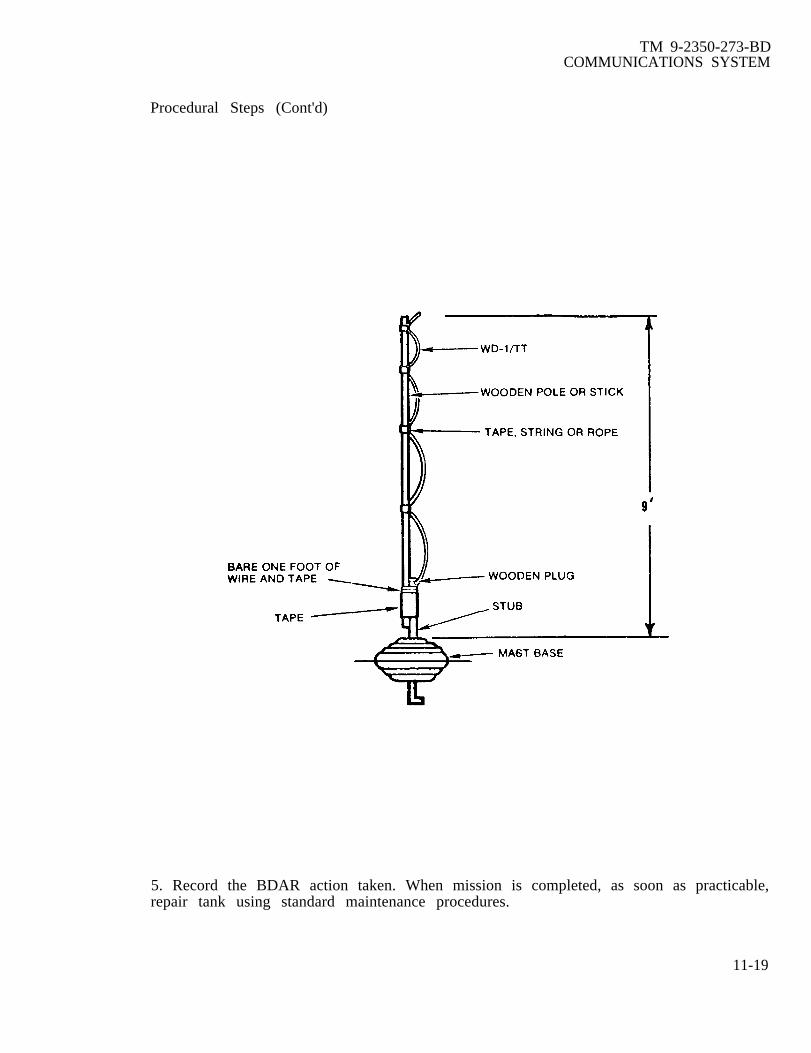
TM 9-2350-273-BDCOMMUNICATIONS SYSTEM
Procedural Steps (Cont'd)
5. Record the BDAR action taken. When mission is completed, as soon as practicable,repair tank using standard maintenance procedures.
11-19

TM 9-2350-273-BDCOMMUNICATIONS SYSTEM
11-19. METALLIC WHIP ANTENNA REPLACEMENT; LONG WIRE ANTENNA
General Information:This procedure gives instructions for the construction of a long wire antenna for usewith the auxiliary receiver if the auxiliary antenna is broken or has been diverted foruse with the receiver/transmitter.
Limitations:● Cannot be used for transmission.● Reduction in reception.
Personnel/Time Required:● 1 soldier● 5 minutes
Material/Tools:● Cable, telephone, WD-l/TT 8-foot length.● Tape, electrical.
Other Options:● Repair broken metallic whip antenna (Refer to para. 11-17.)● Field expedient metallic whip antenna. (Refer to para. 11-18.)● Field expedient ground plane antenna. (Refer to para. 11-21.)
Procedural Steps:
CAUTION
Do not use this antennathe radio equipment.
for transmission. It could damage
1. Strip approximately two inches of insulation from both leads on one end of thetelephone cable.
2. Attach one bare lead to a screw on the R-442 auxiliary receiver.
3. Attach the other bare lead to the center of the antenna connection on the receiverby bending the wire double and jamming it into the hole.
4. Tape or tie the wire to the antenna connector to prevent it from being pulled orvibrated out of the hole.
5. Throw the loose end of the wire out the loader’s hatch.
6. Record the BDAR action taken. When the mission is completed, as soon aspracticable, repair vehicle using standard maintenance procedures.
11-20

TM 9-2350-273-BDCOMMUNICATIONS SYSTEM
11-20. FIBERGLASS WHIP ANTENNA REPLACEMENT
General Information:Since it is not practical to splint a broken fiberglass whip, this procedure givesinstructions for construction of a field expedient antenna if no other antenna isavailable.
Limitations:● Loader’s hatch cannot be completely closed.● May result in degraded performance.
Personnal/Time Required:● 1 soldier● 30 minutes
Materials/Tools:● Cable, coaxial, RG-8 (NSN 6145-00-161-0887) or RG-58 (NSN 6145-00-161-0908), 20-foot length● Pencil, nail or sharp stick● Pole, wooden or stick, 10-foot length● Rope● Tape electrical
Other Options:● Utilize the R-442 auxiliary receivercables between receiver/transmitter.● Replace antenna with: field expedient
Procedral Steps:
1. Measure off and mark but do not cut
metallic whip antenna by exchanging coaxial
ground plane antenna. (Refer to para. 11-21.)
five feet of coaxial cable.
2. In one foot steps, strip the outer insulation from the cable to expose the braidedshield wire. Use care so that the shield wire is not cut.
3. Bend the cable into a loop, holding it with one hand. Using a pencil or nail, and asclose to the remaining insulation as possible, carefully separate the braided shield fromthe insulated center conductor.
4. Work the pencil or nail between the shield wire and center conductor to form ahole. While keeping the loop formed, place a finger in the hole and slowly pull thecenter conductor out of the shield.
5. Tape the center conductor to the top portion and the braided shield to the bottomportion of a ten-foot pole. Tape as necessary to hold cable securely in place.
11-21

TM 9-2350-273-BDCOMMUNICATIONS SYSTEM
Procedural Steps (Cont'd)
6. Fasten @e to antenna base with rope or tape.
7* Feed remaining coaxial cable through loader’s hatch to the radio.
8. If there is a BNC connector (twist type lock) on the cable, attach it to the radioantenna connector. If not, do as follow
a. Carefully strip the outer insulation of the coaxial cable to expose enoughbraided shield to reach a screw near the antenna connector on the radio case.
b. Use a pencil or nail and carefully separate the braided shield from around thecenter conductor. Twist into a pigtail.
c. Strip the inner insulation to expose enough center conductor to push into theantenna connector.
d. Wedge the center conductor into the antenna connector and attach the pigtailto a screw on the radio case.
9. Record the BDAR actionpracticable, repair vehicle using
taken. When the mission is completed, as soon asstandard maintenance procedures.
11-22
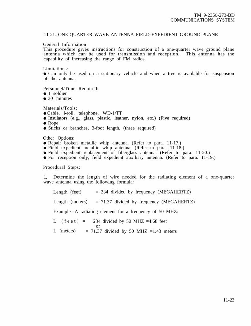
TM 9-2350-273-BDCOMMUNICATIONS SYSTEM
11-21. ONE-QUARTER WAVE ANTENNA FIELD EXPEDIENT GROUND PLANE
General Information:This procedure gives instructions for construction of a one-quarter wave ground planeantenna which can be used for transmission and reception. This antenna has thecapability of increasing the range of FM radios.
Limitations:● Can only be used on a stationary vehicle and when a tree is available for suspensionof the antenna.
Personnel/Time Required:● 1 soldier● 30 minutes
Materials/Tools:● Cable, l-roll, telephone, WD-1/TT● Insulators (e.g., glass, plastic, leather, nylon, etc.) (Five required)● Rope● Sticks or branches, 3-foot length, (three required)
Other Options:● Repair broken metallic whip antenna. (Refer to para. 11-17.)● Field expedient metallic whip antenna. (Refer to para. 11-18.)● Field expedient replacement of fiberglass antenna. (Refer to para. 11-20.)● For reception only, field expedient auxiliary antenna. (Refer to para. 11-19.)
Procedural Steps:
1. Determine the length of wire needed for the radiating element of a one-quarterwave antenna using the following formula:
Length (feet) = 234 divided by frequency (MEGAHERTZ)
Length (meters) = 71.37 divided by frequency (MEGAHERTZ)
Example- A radiating element for a frequency of 50 MHZ:
L ( f e e t ) = 234 divided by 50 MHZ =4.68 feetor
L (meters) = 71.37 divided by 50 MHZ =1.43 meters
11-23

TM 9-2350-273-BDCOMMUNICATIONS SYSTEM
Procedural Steps (Cont'd)
2. Cut the required length from telephone wire.
3. Cut three reflector elements approximately the same length as the radiatingelement. Strip the insulation from one end of the three reflectors. Twist together andconnect to an insulator.
4. Tie together three sticks, approximately the same length as the radiating element,to form a triangular support for the lower end of the reflector elements.
5. Connect the lower end of the reflector elements and triangular support using threeinsulators.
6. Connect one end of the radiating element to the insulator at the upper end of thereflector elements. Make sure radiator does not touch the three reflectors.
7. Connect an insulator and a suspension rope or wire to the upper end of theradiating element. If wire is used for suspension, make sure suspension wire does nottouch the radiator.
11-24

TM 9-2350-273-BDCOMMUNICATION SYSTEM
Procedural Steps (Cont'd)
8. Cut a piece of telephone cable long enough to reach from the radio to the desiredheight of the antenna.
9. Strip the insulation from one end of the two cable wires. Untwist the wires enoughto splice one wire to a bare section of the radiating element and the other wire to abare section of the reflectors.
10. Toss the suspension rope or wire over the limb of a tree, and pull the antenna up tothe desired height.
11. Strip insulationwire to a screw onantenna connector.
from the other endthe radio (ground)
of the two-wire cable.and the other wire to
Untwist and connect onethe center of the radio
12. If communications are not satisfactory, reverse the connections at the radio.
13. Record the BDAR action taken. When the mission is completed, as soon aspracticable, repair vehicle using standard maintenance procedures.
11-22. INTERCOMMUNICATIONS SYSTEM FIELD EXPEDIENT
General Information:This procedure gives instructions for constructing field expedient intercoms.
Limitations:● If the AM-1780 is non-operational, the radio systems will not be usable through theintercom.
Personnel/Time Requred:● 1 soldier● 10 minutes
Materials TOOls:● One TA-312/PTintercom exists.
or TA-l/PT field telephone for each station where requirement for
● Cable, telephone, WD-1/TT, 10 to l5-foot length.
Other Option(s):● Replace with Soviet R-124 intercom. (Refer to paragraph 11-28).
CAUTION
Do not crank or ring the field telephone because damagecould occur to the AM-1780 and/or the entire AN/VIC-1system.
11-25

TM 9-2350-273-BDCOMMUNICATIONS SYSTEM
Procedural Steps:
1. If one or more of the control boxes becomes inoperable but the AM-1780 is stilloperational, install TA-312 or TA-1 field telephones at the station(s) where the badcontrol boxes are located and run field telephone wire back to the AM-1780. The WD-l/TT should be hooked upon the “line” jacks of the AM-1780.
2. If the AM-1780 is not operational, replace the entire intercom system with TA-312or TA-1 telephones and field telephone wire. Run the wire in a circle throughout thevehicle so that all telephones are connected to the same wire.
3. Record the BDAR action taken. When the mission is completed, as soon aspracticable, repair vehicle using standard maintenance procedures.
11-26

TM 9-2350-273-BDCOMMUNICATIONS SYSTEM
11-23. FIELD EXPEDIENT RADIO SYSTEMS
General Information:There are no known methods of constructing a field expedient radio. It should be noted,however, that hand signals, signal, flags, flashlights, telephones, and messengers can beused in place of a radio. Communications can be restored by substituting optionalequipment identified below. It should also be noted that if the intercom is not fullyoperational and the radio is operational but will not work with the intercom, radiocommunications can be partially restored by connecting the CVC helmet or an H-189handset directly to the radio. Further, if the receiver transmitter is damaged, theauxiliary receiver can be tuned to the proper frequency and used for reception only.
Limitations:● Depending on extent of equipment damage or failure, partial to total loss of radiocommunications.
Personnel/Time Required:● 1 soldier● 30 minutes
Materials/Tools:● Cable, telephone, WD-1/TT,● Field Telephone TA-312/PT, or TA-1/PT● Flag set
Procedural Steps:
1. Substitute radio with:
a. AN/VRC-12 series on foreign equipment. (Refer to para. 11-25.)
b. Soviet equipment. (Refer to para. 11-26.)
c. Foreign Allied equipment. (Refer to para. 11-27.)
2. Record the BDAR action taken. When the mission is completed, as soon aspracticable, repair tank using standard maintenance procedures.
11-24. FIELD EXPEDIENT RADIO MOUNT REPAIR
General Information Because of the configuration of plugs and jacks located on themount and the way that the radio sets and mounts are mated, the fixes are very limited.Power and signal cables are routed in and out of the mount through cables and plugs andin turn with a plug and jack method to the radio. If any of those plugs and jacks aredamaged, the only feasible alternative is to replace the mount.
Limitations:● None.
Personnel/Time Required:● 1 soldier● 45 minutes
11-27

TM 9-2350-273-BDCOMMUNICATIONS SYSTEM
Procedural Steps:
1. Turn off power to the radios.
2. Remove radio from damaged mount.
3. Carefully remove damaged mount from vehicle.
4. Remove all cables from damaged mount and note their positions.
5. Remove undamaged plugs from mount and reconnect them to the proper cables.
6. Check for blown fuse in mount. The fuse junction box is located on top of radioreceptacle plug. Replace a blown fuse with a piece of solder or wire.
FOR TEMPORARY FUSECONNECT LENGTH OF SOLDER
BETWEEN SCREWS
MT- 1029. Junction Box Cover
7. Turn power on.
8. Measure voltage on J-21 (Power Cable) at terminals a (negative) and B (positive).Voltage should be between 22 and 30 VDC.
9* Turn power off.
10. Attach radio receptacle plug to radio.
11. Strap or tie down radio to prevent falling.
12. Make sure radio is grounded by connecting a wire from a screw on the radio to anyconvenient screw or bolt on the vehicle.
13. Turn on power and radio. Check radio for power operation.
14. Record the BDAR action taken. When the mission is completed, as soon aspracticable, repair the vehicle using standard maintenance procedures.
11-28

TM 9-2350-273-BDCOMMUNICATIONS SYSTEM
11-25. FOREIGN EQUIPMENT INTERCHANGEABILITY (AN/VRC-12 SERIES)
General Information:This procedure contains interchangeability information to be used if standard radiocomponents are not available.
Limitation:● None.
Personal/Time Required:● 1 soldier● 15 minutes
Materials/Tools:● Component, radio, AN/VRC-12 series from foreign vehicle.
Other Options:● Field expedient radio systems. (Refer to para. 11-23.)● Replace radio with:
1. Soviet equipment. (Refer to para. 11-26.)2. Foreign allied equipment. (Refer to para. 11-27.)
Procedural Steps:
1. The following foreign countries use the standard AN/VRC-12 series radio which canbe installed in the US model tanks with no modifications required using standardprocedures:
a. Belgium d. Netherlandsb. Israel e . S p a i nc. South Korea f. Sweden
2. Record the BDAR action taken. When the mission is completed, as soon aspracticable, repair vehicle using standard maintenance procedures.
11-26. FOREIGN EQUIPMENT INTERCHANGEABILITY (SOVIET RADIO R-123M)
General Information:This procedures gives installation and operating instructions for the Soviet R-123Mtransceiver.
Limitations:● This radio cannot be wired through the AN/VIC-1 intercom. Therefore, it can only beused by one man.
Personnel/Time Required:● 1 soldier● 1 hour
11-29

TM 9-2350-273-BDCOMMUNICATIONS SYSTEM
Materials/Tools:● Wire, 4-conductor, 18-gauge 5-foot length or cable, telephone, WD-l/TT, 5-footllength, (two required) (cut back three steel strands of the two sections)●
●
●
●
●
●
●
●
Connector, UG-273Handset, H-189/GR, or standard CVC helmetPlate, Soviet chestTransceiver, Soviet, R-123M (with power supply)Wire, 2-conductor, 12-gauge (minimum size), 3-foot lengthRope, lo-foot lengthGun, solderingSolder, rosin-core
Other Options:● Substitute radio with:
1. Foreign allied equipment (Refer to para. 11-27).2. Foreign AN/VRC-12 series equipment. (Refer to para. 11-25.)
Procedural Steps:
NOTE
The AN/VIC-1 intercom should not have the R-123M wiredthrough it. For proper operation of the intercom while theR-123M is being used, set the INSTALLATION SWITCH onthe AM-1780 to INT ONLY position.
1. Locate the power cable that runs from the turret wall to connection J-21 on thebottom of MT-1029. Remove the cable from the J-21 connection. Without removingthe connector from the cable, strip back and remove approximately four inches of theouter insulation. Stagger the splices, and scrape approximately 1/4 to l/2-inch of theinner insulation off each of the four wires in the cable.
2. Use a jumper cable of at least 12-gauge wire, and attach both the red and thewhite wires in this power cable to the positive side of the Soviet power supply. (PointA.)
11-30

TM 9-2350-273-BDCOMMUNICATIONS SYSTEM
Procedural Steps (Cont'd)
3. Use another jumper cable of at least 12-gauge wire, and attach both the black andthe green wires in this power cable to the negative side of the power supply. (Point B.)
4. Install the R-123M onto the MT-1029, and tie down with rope or web sling.
5. Remove the outer cover on the female end of the UC-273 connector to make it amale connector and insert it into the antenna connection point located on the right sideof the R-123M immediately below the AHTEHHA sign. Attach the RF cable.
NOTE
o Frequency must be set manually on the MX6707. Ifpossible use the auxiliary antenna.
o Use the four-conductor wire to hook up either a H- 189handset or a CVC helmet to the Soviet chest plate.
11-31

11-32
TM 9-2350-273-BDCOMMUNICATlONS SYSTEMS
Procedural Steps (Cont'd)
6. H-189 Handset:
a. Insert and connect the four wires through the handset to the black, white,green, and red wire connections on the switch.
b. Hook the black wire to one of the inside jacks on the Soviet chest plate and thewhite wire to the other inside jack. (Points A and B.)
c. Hook the green wire connection to one of the outside jacks and the red wire tothe other outside jack (points C and D).
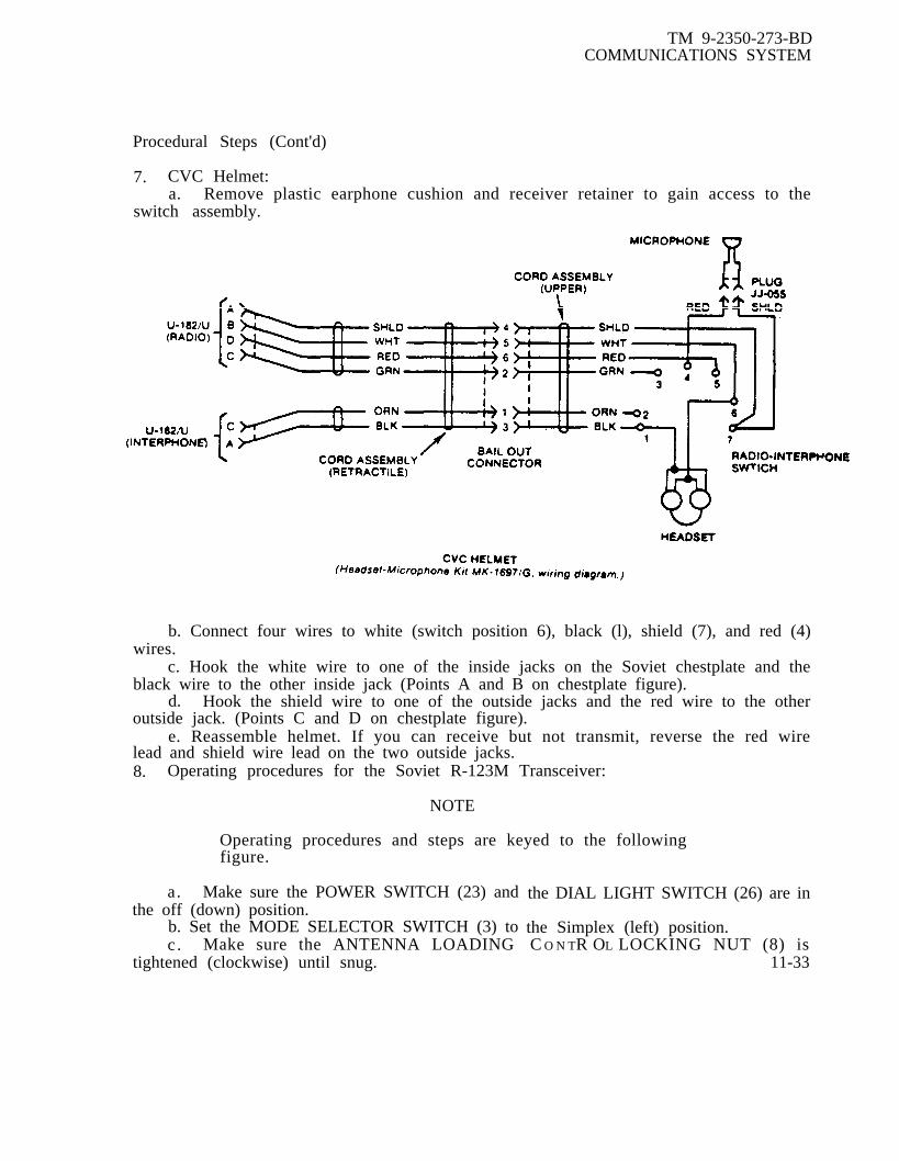
TM 9-2350-273-BDCOMMUNICATIONS SYSTEM
Procedural Steps (Cont'd)
7. CVC Helmet:a. Remove plastic earphone cushion and receiver retainer to gain access to the
switch assembly.
b. Connect four wires to white (switch position 6), black (l), shield (7), and red (4)wires.
c. Hook the white wire to one of the inside jacks on the Soviet chestplate and theblack wire to the other inside jack (Points A and B on chestplate figure).
d. Hook the shield wire to one of the outside jacks and the red wire to the otheroutside jack. (Points C and D on chestplate figure).
e. Reassemble helmet. If you can receive but not transmit, reverse the red wirelead and shield wire lead on the two outside jacks.8. Operating procedures for the Soviet R-123M Transceiver:
NOTE
Operating procedures and steps are keyed to the followingfigure.
a. Make sure the POWER SWITCH (23) andthe off (down) position.
b. Set the MODE SELECTOR SWITCH (3) toc . Make sure the ANTENNA LOADING
tightened (clockwise) until snug.
the DIAL LIGHT SWITCH (26) are in
the Simplex (left) position.C O N TR OL LOCKING NUT (8) is
11-33

TM 9-2350-273-BDCOMMUNICATIONS SYSTEM
Procedural Steps (Cont'd)
d. Turn the SQUELCH CONTROL KNOB (2) counterclockwise (off).e. Turn the VOLUME CONTROL KNOB (16) all the way clockwise.
Turn the VOLTAGE CHECK/OPERATE SWITCH (28) to the receiver circuitsportion of the scale; 1,2B (approximately the one o’clock position).
& Turn the power source on. The input voltage to the R-123M power supplyshould be 24 + 1 vDC for best operation.
11-34
TM 9-2350-273-BDCOMMUMCATIONS SYSTEM
Procedural Steps (Cont'd)
h. Turn the POWER SWITCH (23) and the DIAL LIGHT SWITCH (26) to the on (up)position. At this time the FREQENCY DIAL VIEWING WINDOW (5) and theINDICATOR METER (12) will light. After the tubes are heated, a rushing noise will beheard in the earphones. Adjust the VOLUME CONTROL KNOB (16). for the desiredvolume level.
Check the power supply in the receive mode by noting the reading on theINDICATOR METER (12) and turning the VOLTAGE CHECK/OPERATE SWITCH (28)clockwise to the 6,3B and the 150B positions. The needle on the INDICATOR METER(12) should be in the shaded portion of the scale for all three readings. If not in theshaded portion, check the power supply for bad fuses and replace any bad ones.
CAUTION
The receiver and transmitter are tunedsimultaneously. Do not operate thetransmitter without using an antenna ordummy load. Transmitting into an antennabase without connecting an antenna maydamage the transmitter portion of the radio.
j=Check the power supply in the transmit mode by placing the VOLTAGE
CHECK/OPERATE SWITCH (28) to the 1,2B position on the transmitter circuits portionof the scale (approximately the 7 o’clock position). The INDICATOR METER (12) shouldread in the shaded portion of the scale. If not in the shaded portion, check the powersupply for bad fuses and replace any bad ones.
k. Place the VOLTAGE CHECK/OPERATE SWITCH (28) in the 150B position byrotating the switch clockwise. Momentarily place the chest plate switch and the CVChelmet or H-189 switch in the transmit position. Note the reading on the INDIATORMETER (12~ it should be in the shaded portion of the scale. Release the switches.
1. Place the VOLTAGE CHECK/OPERATE SWITCH (28) alternately in the 250Band 600B positions by rotating the switch clockwise. To obtain an indication, it isnecessary to momentarily depress the switches to transmit. Both the readings should bein the shaded portion of the scale.
. Place the VOLTAGE CHECK/OPERATE SWITCH (28) in the operate # 1(PAbOTA 1) position.
n. Place the PRESET CHANNEL/CONTINUOUS TUNE SELECTOR SWITCH (18)in either the I or II position. Position I will be used if the desired operating frequency isbetween 20 and 35.75 MHZ and position II will be selected if the desired operatingfrequency will be between 35.8 to 51.5 MHZ. Band selections are also shown by theBAND INDICATOR (13) lights.
11-35

TM 9-2350-276-BDCOMMUNICATIONS SYSTEM
Procedural Steps (Cont'd)
o. To calibrate the FREQUENCY DIAL, rotate the FREQUENCY TUNING KNOB(27) while looking into the FREQUENCY DIAL VIEWING WINDOW (5) and select thefrequency listed below that is the closest to the desired operating frequency.
Band I: 22.050 MHZ 28.350 MHZ 34.650 MHZ
Band H: 36.225 MHZ 40.950 MHZ 42.525 MHZ 45.675 MHZ 48.825 MHZ
The frequencies are noted on the frequency dial with an extended graduation linecapped by an arrowhead.
P. Set the MODE SELECTOR SWITCH (3) to the receive only (right) position.
q* Depress and hold the TONE CALL BUTTON (25). A tone should be heard inthe earphones. Rotate the FREQUENCY TUNING KNOB (27) until a zero beat isobtained. While rotating the FREQUENCY TUNING KNOB (27) the tone should beheard to progress from a high pitch to a low pitch then to a high pitch again. Theproper setting of the FREQUENCY TUNING KNOB (27) is the point at which the tone isat its lowest pitch or totally absent.
Note the relative positions of the index line and the frequency graduation linethrough the FREQUENCY DIAL VIEWING WINDOW (5). If the index line is within 1/5of a frequency graduation (5 KHZ), no adjustment of the index line is necessary.Proceed after releasing the TONE CALL BUTTON (25). If the index line is not within1/5 of a graduation (5 KHZ) the following adjustments must be made:
1. Release the TONE CALL BUTTON (25). Using a screwdriver, remove theINDEX LINE ADJUSTMENT (4) plug.
NOTE
This adjustment is quite stiff. Care should be exercised tonot change the frequency setting while adjusting the indexline.
2. Insert the screwdriver into the hole disclosed and contact the index lineadjustment. Rotate the adjustment right or left until the index line exactly correspondsto the selected frequency graduation line.
3. Replace the INDEX LINE ADJUSTMENT (4) plug.
4. Check the setting by repeating steps (q) and (r). When no adjustment isrequired, proceed to the next step.
s. Return the MODE SELECTOR SWITCH (3) to the Simplex position (left).
11-36

TM 9-2350-273-BDCOMMUNICATIONS SYSTEM
Procedural Steps (Cont'd)
t . Set the PRESET CHANNEL/CONTINUOUS TUNE SELECTOR SWITCH (18) tothe preset #1 position.
u. Set the PRESET CHANNEL BAND SELECTOR (11) to correspond with thedesired band. Frequencies between 20.0 and 35.75 MHZ are set on Band I (switch up);frequencies between 35.8 and 51.5 HMZ are set on Band 11 (switch down). Bandselections are indicated by the BAND INDICATOR lights (13).
v. Open the PRESET LOCKING SCREW ACCESS COVER (19) on the front paneland loosen the PRESET LOCKING SCREW (6) marked "1“ by turning the locking screwcounterclockwsie until the slot is at right angles with the red circle. To release thepreset locking screw, use the special key (not shown) attached to the case of the radio.
w. Turn the FREQUENCY TUNING CONTROL KNOB (27) to the desiredfrequency by aligning the desired frequency with the indicator line within theFREQUENCY DIAL VIEWING WINDOW (5). While holding the FREQUENCY TUNINGCONTROL KNOB (27) turn the PRESET LOCKING SCREW (6) clockwise with thespecial key until it is aligned with the red circle.
x. Loosen the ANTENNA LOADING CONTROL LOCKING NUT (8) two or threeturns counterclockwise.
. Put the chest plate switch in the transmit position and hold. Turn theANTENNA LOADING CONTROL KNOB (9) for maximum deflection on the INDICATORMETER (12) and maximum brilliance on the RF INDICATOR LAMP (7).
NOTE
Several peaks will be noted on the indicator meter whileloading the antenna. Tune to the maximum peak and to themaximum brilliance on the indicator lamp. For a moresensitive meter to help chooose between peaks, turn theVOLTAGE CHECK/OPERATE SWITCH (28) to the operate#2 (PAbOTA 2) position. After determining the mostadvantageous loading position, return the VOLTAGECHECK/OPERATE SWITCH (28) to the operate #1 (PAbOTA1) position. Release the chest plate switch.
z. While holding the ANTENNA LOADING CONTROL KNOB (9), tighten theANTENNA LOADING CONTROL LOCKING NUT (8). Check this step by depressing thechest plate switch to the transmit position. If the indication on the INDICATORMETER (12) is not the same as noted in step (y), loosen the ANTENNA LOADINGCONTROL LOCKING NUT (8) and repeat step (y). If proper loading has beenaccomplished release the chest plate switch and proceed.
11-37

TM 9-2350-273-BDCOMMUNICATIONS SYSTEM
Procedural Steps (Cont’d)
aa. Repeat steps (s) through (w) to preset frequencies on settings 2, 3, and 4.
NOTE
Only two frequencies can be preset on Band I and two morecan be preset on Band II. Example: If the PRESETCHANNEL BAND SELECTOR (11) is set at Band I positionfor preset #1 and #2, only Band II frequencies can beselected for presets #3 and #4. Any combination of bandsand presets may be used.
ab. You are now ready to operate in the preset mode. Any time you want toselect a preset frequency, simply turn the PRESET CHANNEL/CONTINUOUS TUNESELECTOR SWITCH (18) to the desired preset number.
ac. To operate in theCHANNEL/CONTINUOUS TUNElabelled I and II. “I” correspondsfrequencies.
continuous tuneSELECTOR SWITCHto Band I frequencies
mode, turn the PRESET(18) to the lower positions,
and “II” corresponds to Band H
ad. Turn the FREQUENCY TUNING KNOB (27) to the desired frequency.
ae. Load the antenna by accomplishing steps (w) thru (z).
CAUTION
Observe a 1:3 transmit to receive ratio e.g., 3 minutestransmit to 9 minutes receive, to minimize the possibility ofoverheating the power supply and power output tubes.
af. You are now ready to operate in the continuous tune mode. The tuningcontrols are very sensitive; therefore, the continuous mode should not be selected if theradio is to be moved or subjected to vibrations.
9. Record the BDAR action taken. When the mission is completed, as soon aspracticable, repair tank using standard maintenance procedures.
11-38
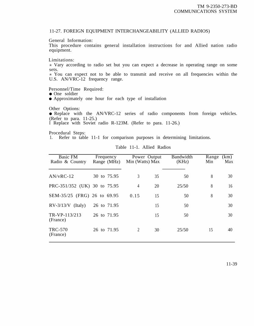
TM 9-2350-273-BDCOMMUNICATIONS SYSTEM
11-27. FOREIGN EQUIPMENT INTERCHANGEABILITY (ALLIED RADIOS)
General Information:This procedure contains general installation instructions for and Allied nation radioequipment.
Limitations:✬ Vary according to radio set but you can expect a decrease in operating range on somesets.✬ You can expect not to be able to transmit and receive on all frequencies within theU.S. AN/VRC-12 frequency range.
Personnel/Time Required:● One soldier● Approximately one hour for each type of installation
Other Options:● Replace with the AN/VRC-12 series of radio components from foreign vehicles.(Refer to para. 11-25.)l Replace with Soviet radio R-123M. (Refer to para. 11-26.)
Procedural Steps:1. Refer to table 11-1 for comparison purposes in determining limitations.
Table 11-1. Allied Radios
Basic FM Frequency Power Output Bandwidth Range (km)Radio & Country Range (MHz) Min (Watts) Max (KHz) Min Max
AN/vRC-12 30 to 75.95 3 35 50 8 30
PRC-351/352 (UK) 30 to 75.95 4 20 25/50 8 16
SEM-35/25 (FRG) 26 to 69.95 0.15 15 50 8 30
RV-3/13/V (Italy) 26 to 71.95 15 50 30
TR-VP-113/213 26 to 71.95 15 50 30(France)
TRC-570 26 to 71.95 2 30 25/50 15 40(France)
11-39

TM 9-2350-273-BDCOMMUNICATIONS SYSTEM
Procedural Steps (Cont'd)
NOTE
The Allied countries listed in the table have agreed toutilize the same connectors for cables within the radiosystem. All power cable connectors should be the sameregardless of which country's radio is examined.
2. Remove the radio and its accompanying mount from the foreign vehicle. Notewhich cable connector supplies power to the mount.
3. Remove the radio and its accompanying mount from your vehicle. Note that thepower cable is J-21.
4. Install the foreign vehicle radio and mount in the place vacated by the USAN/vRC-12.
5. Install the cable that previously ran to 3-21 in the connector socket for input poweron the foreign radio mount.
6. If the foreign vehicle had an intercom system, hook up the cable that runs betweenJ-22 on the U.S. radio mount and 3-501 on the AM-1780. This cable must be hooked upto the same connections to which the foreign vehicle intercom master control box wasconnected.
7. Be sure to take one foreign vehicle CVC helmet for use in case the U.S. CVChelmet will not adapt to the front of the foreign radio. Prior to using the foreign CVChelmet at the radio face, attempt to operate the radio through the AM-1780. If theAM- 1780 does not key the foreign radio then there is a wiring difference and theforeign CVC helmet can be connected directly to the microphone input connection onthe front face of the foreign radio.
8. Record the BDAR taken. When the mission is completed, as soon as practicable,repair tank using standard maintenance procedures.
11-28. REPLACE AN/VIC INTERCOM WITH SOVIET R-124 INTERCOM
General Information:This procedure gives installation and operating instructions for the Soviet R-124intercom.
Limitations:● The AN/VRC-12 series radio cannot be wired through this intercom. Therefore, theradio can only be operated by one man.
11-40

TM 9-2350-273-BDCOMMUNICATIONS SYSTEM
Personnel/Time Required:● 1 soldier● 1 hour
Materials/Tools:● Handset, H-189/6R, (each chestplate), or standard CVC helmet● Intercom, Soviet, R-124● Plate, chest, Soviet (one for each control box)● Tape, electrical.● Wire, 4-conductor, 18-gauge, 5-foot length or cable, telephone, WD-l/TT, 5-footlength (two required)● Gun, soldering● Solder, rosin-core
Other Option:● Field expedient intercom (refer to para. 11-22).
Procedural Steps:
NOTE
All wires in the R-124 interconnecting cables are soldereddirectly to the internal connecting points in the individualboxes. Use care in removal/installation. Do not disconnectindividual boxes unless absolutely necessary.
1. Remove the R-124 from Soviet vehicle and install in U.S. vehicle.
2. Wire the H-189/GR handset or CVC helmet using the procedures listed in para.11-26.
NOTE
Power is obtained in the same manner as listed in step 1 of para. 11-26.
3. Attach the red and white wires from the power cable to the black terminal on thebottom of the A-1 box of the R-124. Attach the black and green wires from the powercable to the ground strap on the A-l box. See position 6 in the following illustration.
11-41

TM 9-2350-273-BDCOMMUNICATIONS SYSTEM
procedural Steps (Cont'd)
4. Operating procedures for the R-124.
NOTE
Operating Procedures are keyed to the intercom.
1. A-1 MAIN JUNCTION BOX2. FUNCTION SWITCH3. FUSE4. VOLUME CONTROL5. CVC RECEPTACLE6. VOLTAGE CONNECTION POINT7. R-112 CONNECTION CABLE8. R-123 CONNECTION CABLE I NOT SHOWN)
9. A-4 TERMINATING BOX10. CVC RECEPTACLE11. A-3 INTERCONNECTING BOX12. CVC RECEPTACLE13. A-2 CONTROL BOX14. CVC RECEPTACLE15. FUNCTION SWITCH
a. Connect the CVC helmet to the chest plate switch. Connect the chest plateswitch to any of the R-124 receptacles (5, 10, 12, or 14 in the intercom figure).
b. Set FUNCTION SWITCH (2) and FUNCTION SWITCH (15) to the intercom BCposition. (Both function switches must be in the BC position to allow all four boxesaccess to intercom.)
c. Adjust VOLUME CONTROL (4) for desired audio level in the headsets.
5. Record the BDAR action taken. When the mission is completed, as soon aspracticable, repair tank using standard maintenance procedures.
11-42
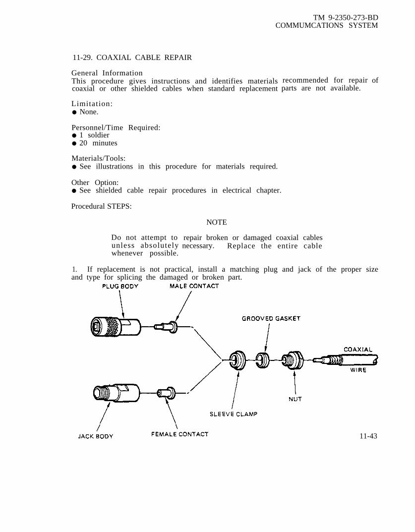
TM 9-2350-273-BDCOMMUMCATIONS SYSTEM
11-29. COAXIAL CABLE REPAIR
General InformationThis procedure gives instructions and identifies materialscoaxial or other shielded cables when standard replacement
Limitation:● None.
Personnel/Time Required:● 1 soldier● 20 minutes
Materials/Tools:● See illustrations in this procedure for materials required.
Other Option:● See shielded cable repair procedures in electrical chapter.
Procedural STEPS:
Do not attempt tounless absolutelywhenever possible.
recommended for repairparts are not available.
NOTE
repair broken or damaged coaxial cables necessary. Replace the entire cable
of
1. If replacement is not practical, install a matching plug and jack of the proper sizeand type for splicing the damaged or broken part.
11-43
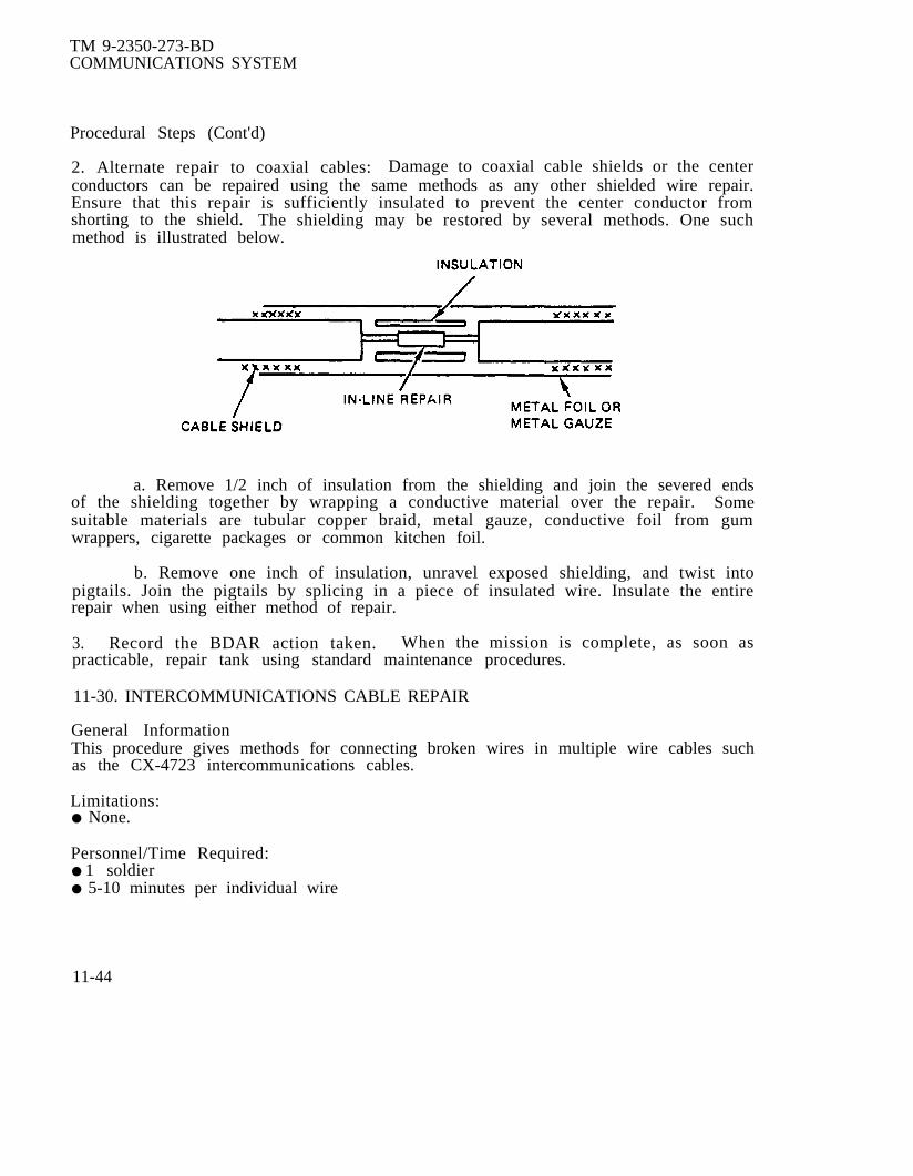
TM 9-2350-273-BDCOMMUNICATIONS SYSTEM
Procedural Steps (Cont'd)
2. Alternate repair to coaxial cables: Damage to coaxial cable shields or the centerconductors can be repaired using the same methods as any other shielded wire repair.Ensure that this repair is sufficiently insulated to prevent the center conductor fromshorting to the shield. The shielding may be restored by several methods. One suchmethod is illustrated below.
a. Remove 1/2 inch of insulation from the shielding and join the severed endsof the shielding together by wrapping a conductive material over the repair. Somesuitable materials are tubular copper braid, metal gauze, conductive foil from gumwrappers, cigarette packages or common kitchen foil.
b. Remove one inch of insulation, unravel exposed shielding, and twist intopigtails. Join the pigtails by splicing in a piece of insulated wire. Insulate the entirerepair when using either method of repair.
3. Record the BDAR action taken. When the mission is complete, as soon aspracticable, repair tank using standard maintenance procedures.
11-30. INTERCOMMUNICATIONS CABLE REPAIR
General InformationThis procedure gives methods for connecting broken wires in multiple wire cables suchas the CX-4723 intercommunications cables.
Limitations:● None.
Personnel/Time Required:● 1 soldier● 5-10 minutes per individual wire
11-44

TM 9-2350-273-BDCOMMUNICATIONS SYSTEM
Materials/Tools:● Knife● Tape● Soldering iron● Solder, rosin-core
Other Options:● See other methods for splicing wires and cables in the electrical chapter in this TMand TM 9-2350-276-BD.
Procedural Steps:
1. Turn off power or unplug cable at both ends if possible or at end nearest thedamaged area.
2. Peel back outside insulation about 3 inches on each side of damaged area.
3. Identify wires with broken insulation only and those with actual separated wires.
4. Tape those with broken insulation but with wire intact.
5. Cut clean ends on broken wires.
6. Strip insulation back 1/2 inch.
7. Matching color coding on wires, twist together, solder if possible, or tighten withpliers if available.
8. Bend twisted wires back along length of wire.
9. Tape repaired wire with length of tape.
10. When all wires are repaired, tape around entire bundle and try to seal insulationends peeled back in Step 2.
11. Plug cable back into equipment, turn on power, and test.
12. Record BDAR action taken. When the mission is complete, as soon as practicable,repair vehicle using standard maintenance procedures.
11-31. CABLES ARE TOO SHORT BDAR INSTALLATION
General Information:This procedure gives methods for connecting two or more cables together to make thedesired cable length. This procedure is for CX-4723 cable. Other types of cables canbe extended using similar methods.
Limitations:● Preferred method - none.● Alternate methods - possible lowered volume.
11-45

TM 9-2350-273-BDCOMMUNICATIONS SYSTEM
Personnel/Time Required:● 1 soldier● 20 minutes
Materials/Tools:● Preferred method:
Box, control, C-10456 or C-2298 VRC● Alternate method:
Gun, solderingSolder, rosin-core
Other Options:● See other methods for splicing cables in electrical system chapter of this TM and TM9-2350-276-BD.
● The preferred method uses a junction box such as a C-2298 control box between twoCX-4723 cables.
● Another method is fabricating a junction by removing the 3-801 and 3-804 connectorsfrom a C-2298 control box. Solder jumper wires between the corresponding connectorpins. Insulate the jumper wires and the rear of the connectors.
● A less desirable method is to remove one connector from each cable and splice thecorresponding wires from the two cables together. Insulate the splice.
● Record the BDAR action taken. When the mission is complete, as soon aspracticable, repair vehicle using standard maintenance procedures.
11-32. ISOLLATION OF NON-ESSENTIAL SYSTEMS (GENERAL)
General Information:This procedure lists general guidelines for the isolation of non-essential systems.
Limitation:✬ Varies depending on which system is isolated.
Personnel/Time Required:● 1 soldier● 5-30 minutes
Materials/Tools:● Crimp-on end caps, electrical tape or other insulating material.
Other Options:● Insulate/isolate non-essential wiring or cabling with crimp-on end caps, tape, or anyother insulating material. Secure wires to some structure and tag them for rapididentification.
11-46

TM 9-2350-273-BDCOMMUNICATIONS SYSTEM
Other Options (Cont'd)
● Any intercom control box can be considered non-essential if one is willing to operatewithout it. Disconnect the cable leading to that particular control box at AM-1780 andconsider using field expedient means for intercom. Also, consider switching controlboxes and/or cables within the vehicle to provide intercom at the desired points. Forrepairs of this type, existing cabling can be rerouted if the original cables have beendamaged.
Record the BDAR action taken. When the mission is complete, as soon as practicable,repair tank using standard maintenance procedures.
11-33. ISOLATION OF N ON-ESSEN TIAL SYSTEM S (VOLTAGE SUPPRESSORS)
General Information:This procedure gives instructions for the isolation and by-passing of both the MK 2096and the MX-7777/MX-7778 Transient Voltage Suppressors.
Limitations:● Possible loss of all communications.
Personnel/Time Requied:● 1 soldier● 5-10 minutes
Procedural Steps:
CAUTION
Without the transient voltage suppressor in the circuit, voltage spikes will berouted through the communications equipment and damage could occur. By-pass the suppressor only as a last resort.
Option 1. Removal of MK-2096 transient voltage suppressor:
a. Locate the MK-2096 under the radio mount.
b. Unscrew the MK-2096 from the connector.
c. The MK-2096 is now removed from the circuit.
Option 2. Removal of MX-7777/MX-7778 transient voltage suppressor:
a. Locate the MX-7777/MX-7778 in the vicinity of the driver’s compartment.
11-47

TM 9-2350-273-BDCOMMUNICATIONS SYSTEM
Procedural Steps (Cont’d)
b. Remove the CX 10613/G cable which runs between the vehicle powerreceptacle and the rear of the voltage suppressor.
c. Remove the Bendix connector which is attached to one ofon the top of the suppressor.
two possible plugs
d. Plug this Bendix connector directly into vehicle power receptacle.
e. The suppressor is now out of the circuit.
Record the BDAR action taken. When the mission is complete, as soon as practicable,repair tank using standard maintenance procedures.
11-34. GENERAL INTERCHANGEABILITY INFORMATION
General Information;Repairs made to combat damaged equipment should be the same as repairs made duringthe normal maintenance posture. However, due to the extreme nature of damage thatmight be found in combat-damaged equipment, normal maintenance procedures mightnot be sufficient. In the interest of rapidly repairing damage to communications systemin this situation, it will often be faster to exchange some components rather than repairthem. The following is a partial listing of interchangeable parts for the AN/VIC-1 andthe AN/VRC-12 as installed in most common tracked vehicles on the battlefield. It isprovided as a guide only and is not necessarily y a complete listing of all componentsfrom other vehicles that could be substituted. Further assistance can be obtained bystudying the cording diagrams located in paragraph 11-35. This listing considers onlyUS equipment. For information on foreign equipment interchangeability, refer toparagraph 11-25 through 11-28. Any component that has been replaced should be turnedin for repair through the normal channels and thereby returned to the inventory. Whentime permits, route all replaced cables to conform to the original configuration. Ifhaste is essential, route replaced cables as necessary and secure them where possible toprevent damage to the cables.
11-48

TM 9-2350-273-BDCOMMUNICATIONS SYSTEM
INTERCHANGEABILITY LISTING
Nomenclature
1. ANTENNAS
AS-1729
AS-1729
AT- 1095
AT-1730
Auxiliary Antenna
Auxiliary Antenna
MS-116A
MS-117A
MS-118A
MX-6707
AT-912
AB-15
AB-558
2. INTERCOM
AM-1780
C-2296
C-2297
N/A
N/A
Top Element
Bottom Element
N/A
N/A
Bottom Element
Middle Element
Top Element
Matching unit
Matching unit
Mast Base
Mast Base
CompatibleComponent
AS-1729
AuxiliaryAntenna
AT-1095
AS-1730
AT-1095
AuxiliaryAntenna
MS-116A
MS-117A
MS-118A
AT-912
MX-6707
AB-558
AB-15
Amplifier AM-1780
Outside C-2296
Drivers C-2297Control Box
CompatibleVehicle
All with radio
All with Aux.Receiver
All with radio
All with radio
All with radio
All with Aux.Receiver
All with Aux.Receiver
All with AuxReceiver
All with Aux.Receiver
Some with radio
Most with radio
Most with AuxReceiver
Most with Aux.Receiver
Notes
2
1
2
2
2
2
2
2
2
3
3
2
2
All w/AN/VIC-1 2
M60, M551 2AVLB, MAB
M60, M551 2AVLB, MAB
11-49

TM 9-2350-273-BDCOMMUNICATIONS SYSTEM
INTERCHANGEABILITY LISTING (Continued)
Nomenclature
C-2298
C-2298
C-2742
C-10456
C-10456
3. CABLES
CG-1773
CG-1773
CG-1773
CG-1773
CG-1773
CG-1773
CX-4720
CX-4720
CX-4720
CX-4720
CX-4720
CX-4721
CX-4721
11-50
Description
MemberControl Box
MemberControl Box
FrequencySelector Box
Control Box
Control Box
4'0"
5'0"
6'0"
6'6"
7'0"
8'0"
2'0”
3'0"
4'0"
8'0"
10'0”
26”
3'0"
CompatibleComponent
C-10456
C-2298
C-2742
C-10456
C-2298
CG-1773
CG-1773
CG-1773
CG-1773
CG-1773
CG-1773
CX-4720
CX-4720
CX-4720
CX-4720
CX-4720
CX-4721
CX-4721
CompatibleVehicle Notes
M1, M2, M3
All w/AN/VIC/l
All w/RT-246
M1, M2, M3
All w/AN/VIC-l
M113, M88
M151, M2, M3
M60, M578
M561
M60, M151
AVLB, M2, M3
MAB, M561
M151, M561
M113
M110
AVLB
M551,M113, M151
M1, M561
2
2
2
2
1,7
2,5
2,5
2,5
2,5
2,5
2,5
2,5
2,5
2,5
2,5
2,5
2,5
2,5

TM 9-2350-273-BDCOMMUNICATIONS SYSTEM
Nomenclature
INTERCHANGEABILITY LISTING (Continued)
CX-4722
CX-4722
CX-4722
CX-4722
CX-4722
CX-4722
CX-4722
CX-4722
CX-4723
CX-4723
CX-4723
CX-4723
CX-4723
CX-4723
CX-4723
CX-4723
CX-4723
Description
4'0"
3'0"
4'0"
5'0"
6'0"
7'0"
8'0"
20'0"
2'0"
3'0"
4'0"
4'6"
5'0"
6'0"
7'0"
8'0"
9'0"
CompatibleComoponent
CX-4721
CX-4722
CX-4722
CX-4722
CX-4722
CX-4722
CX-4722
CX-4722
CX-4723
CX-4723
CX-4723
CX-4723
CX-4723
CX-4723
CX-4723
CX-4723
CX-4723
CompatibleVehicle
M2, M3
M113
M88
M2, M3
M60, M561
M151, M578
M2, M3
M901
M551, M551MAB
M551, M561M2, M3, MAB
M901, M109
M561
Notes
2,5
2,5
2,5
2,5
2,5
2,5
2,5
2,5
2,5
2,5
2,5
2,5
Ml, M2, M3, M88 2,5M113, M901, M561,M551, M577, AVLB
AVLB 2,5
M1, M2 2,5M3, M110
M2, M88, M110 2,5M151, MAB
M60, M88, M113, 2,5M577, M578, M901
11-51
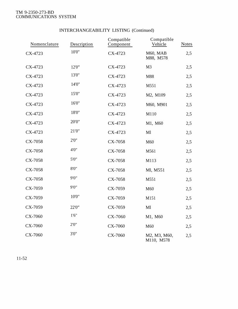
TM 9-2350-273-BDCOMMUNICATIONS SYSTEM
INTERCHANGEABILITY LISTING (Continued)
Nomenclature
CX-4723
CX-4723
CX-4723
CX-4723
CX-4723
CX-4723
CX-4723
CX-4723
CX-4723
CX-7058
CX-7058
CX-7058
CX-7058
CX-7058
CX-7059
CX-7059
CX-7059
CX-7060
CX-7060
CX-7060
Description
10'0"
12'0”
13'0"
14'0"
15'0"
16'0"
18'0"
20'0"
21'0"
2'0"
4'0"
5'0"
8'0"
9'0"
9'0"
10'0"
22'0”
1'6"
2'0"
3'0"
CompatibleComponent
CX-4723
CX-4723
CX-4723
CX-4723
CX-4723
CX-4723
CX-4723
CX-4723
CX-4723
CX-7058
CX-7058
CX-7058
CX-7058
CX-7058
CX-7059
CX-7059
CX-7059
CX-7060
CX-7060
CX-7060
CompatibleVehicle
M60, MABM88, M578
M3
M88
M551
M2, M109
M60, M901
M110
M1, M60
Ml
M60
M561
M113
Ml, M551
M551
M60
M151
Ml
M1, M60
M60
M2, M3, M60,M110, M578
Notes
2,5
2,5
2,5
2,5
2,5
2,5
2,5
2,5
2,5
2,5
2,5
2,5
2,5
2,5
2,5
2,5
2,5
2,5
2,5
2,5
11-52

TM 9-2350-273-BDCOMMUNICATIONS SYSTEM
INTERCHANGEABILITY LISTING (Continued)
Nomenclature
CX-7060
CX-7060
CX-7060
CX-7060
CX-8650
CX-9640
CX-9640
CX-13089
CX-13089
CX-13089
CX-13089
B-4005084
4. CVC HELMETS
CVC
DH-132
5. MOUNTS
MT-1029
MT-1898
MT-3823
Description
4'0"
6'0"
9'0"
14'0"
Y Cord
1'6"
2’6”
2'1"
3'0"
7'0"
10'0”
8'0"
MK-1039
MK-1697
Radio
Aux Receiver
KY-38
CompatibleComponent
CX-7060
CX-7060
CX-7060
CX-7060
CX-8650
CX-9640
CX-9640
CX-13089
CX-13089
CX-13089
CX-13089
CG-1773
DH-132
CVC
MT-1029
MT-1898
MT-3823
CompatibleVehicle Notes
Ml, M2, M60
M110
M2, M3
M3, M578
All w/AN/VIC-l
M109
M109
M109
M88
M2, M3
M578
AVLB, M2, M3
Most withAN/VIC-l
Older Vehiclesw/AN/VIC-l
All with radio
All with Aux.Receiver
All w/KY-38
2,5
2,5
2,5
2,5
2,6
2,5
2,5
2,5
2,5
2,5
2,5
2,5
2,6
2,6
2,8
2,8
2
11-53

TM 9-2350-273-BDCOMMUNICATIONS SYSTEM
INTERCHANGEABILITY LISTING (Continued)
CompatibleNomenclature Description Component
MT-4626 KY-57 MT-4626
AM-2060 RT-841 AM-2060
6. RADIO EQUIPMENT
RT-246
RT-524
RT-841
R-442
Receiver RT-246,Transmitter RT-524,
RT-841
Receiver RT-246,Transmitter RT-524,
RT-841
Receiver RT-246,Transmitter RT-524,
RT-841
Auxiliary R-442Receiver
7. TRANSIENT VOLTAGE SUPPRESSORS
MK-2096 Mini- MK-2096Suppressor
MK-7777, MK-7778 Suppressor MK-2096MK-7778MK-7777
8. SPEECH SECURITY EQUIPMENT
AM-4979 Amplifier AM-4979
J-2731 Distribution J-2731Box
3-3024 Interconnecting 3-3024Box
KY-38 SSE KY-38
11-54
CompatibleVehicle
All w/KY-57
All w/RT-841
All with radio
All with radio
All with radio
AH with Aux.Receiver
M1, M2, M3
All w/AN/VIC-l
M113
M113, M60M577, M578,M88
M88, Ml 13,M577, M578,M60
All w/KY-38
Notes
2
2
2,9
2,9
2,9
2,9
2
2
2
2
2

TM 9-2350-273-BDCOMMUNICATIONS SYSTEM
INTERCHANGEABILITY LISTING (Continued)
Nomenclature Description
KY-57 SSE
Z-ACD( ) Power Unit
9. SSE CABLES FOR KY-38
CX-10475
CX-10475
CX-10475
CX-10539
CX-10539
CX-11996
CX-11996
CX-11996
CX-11996
CX-12126
CX-12126
CX-12195
CX-12195
CX-12195
CX-12925
Power Cable
1'7"
4'0"
10'0"
4'0"
6'0"
6'0" x 3'0"
12'0” x 3’0”
14'0" x 3'0"
10’0” x 5’0”
5'0"
8'0"
4'0"
6'0"
10'0"
6'0"
Y
CompatibleComponent
KY-57
Z-ACD( )
CX-10475
CX-10475
CX-10475
CX-10539
CX-10539
CX-11996
CX-11996
CX-11996
CX-11996
CX-12126
CX-12126
CX-12195
CX-12195
CX-12195
CX-12925
Power Cable
CompatibleVehicle Notes
All w/KY-57 2
All w/KY-38 2
M60 2,5
M113, M88, 2,5M577, M578
M113 2,5
M113, M48, M577 2,5
M113, M60 2,5
M88 2,5
M48, M60 2,5
M60, M113 2,5
M577, 578 2,5M113
M113 2,5
M113 2,5
M578, M88 2,5M113, M577
M113, M48 2,5
M60 2,5
M113 2,5
All w/KY-38 2
11-55

TM 9-2350-273-BDCOMMUNICATIONS SYSTEM
NOTE #1 -
NOTE #2 -
NOTE #3 -
NOTE #4 -
NOTE #5 -
NOTE #6 -
NOTE #7 -
NOTE #8 -
NOTE #9 -
NOTES ASSOCIATED WITH INTERCHANGEABILITY LISTING
System is slightly degraded. Replace with original component as soon aspossible.
No degradation. Continue normal mission.
No degradation, electronically compatible; however, adapter bracket mayhave to be locally fabricated as AT-912 may not bolt into same holes. Alsoantenna element AT- 1096 must be used in lieu of antenna element AS-1730.
This precludes usage of RT-524 and should not be done unless RT-524 isinoperative.
Any cable with the same number can be substituted if it is of an equallength to, or longer than, the cable being replaced. Most of the time ashorter cable can also be used by routing it in the most direct path betweencomponents. Additionally, two shorter cables can be spliced together toattain the desired length.
Ensure for comparability of connector. If the older type CVC helmet issubstituted for the DH-132 series helmet then the cord assembly CX-8650B/GR must also be exchanged with the CVC helmet.
This exchange will remove the capability to key the intercom or radio byany means other than by the switch located on the CVC helmet.
If the mount is from any vehicle other than a vehicle with theAN-WC- 1 intercom then the “Pivot terminal link” must be in positionas shown below.
If the R/T or aux receiver is from a vehicle not utilizing speech securityequipment then the x-mode position switch may have to be
- -
changed. Turn your R/T ON and see below procedures:
A Set the R/T SQUELCH control on OLD ON.
B Remove the cover from the X-MODE receptacle, if the CALL lightcomes on, the switch is in X-MODE
11-56

NOTE
c
D
E
F
G
H
I
J
K
L
TM 9-2350-273-BDCOMMUNICATIONS SYSTEM
BUTif the CALL light does not come on, the switch is in NORMAL.Organizational or higher maintenance should then:
Remove R/T from mount, turn R/T upside down.
Remove bottom cover from R/T.
Loosen assembly A4000 captive screws.
Raise assembly A4000 and lock brace.
Turn X-MODE-NORMAL switch to X-MODE.
Be sure leaf springs are equally curved.
Lower assembly A4000 and tighten captive screws.
Be sure assembly hinge pin is pushed all the way in.
Replace bottom cover of R/T.
Replace R/T on to mount.
If the AUX receiver is to be used in the X-MODE communications hookup itmust be opened up and its switch set to X-MODE.
. .
The AUX receiver switch must be placed in NORMAL after you are through withthe X-MODE hook-up.
#10 - Loss of automatic channel selection if RT-246 is being used.
11-57

TM 9-2350-273-BDCOMMUNICATIONS SYSTEM
Section V. Common Vehicle Cording Diagrams
11-35. General.
Cording diagrams for common U.S. vehicles on the battlefield have beenprovided in this section to aid in identifying components and cables that areinterchangeable. These diagrams also assist in identifying cables without having totrace them throughout the vehicle.
Cording Diagram For: Page
KY-57 General Configuration (Unclassified) . . . . . . . . . . . . . . . . . . . . . . . . . . . . . . . . . . . . . . . . . . . . . . . . 11-60
AN/VIC-l and AN/VRC-12 in M1 Tank . . . . . . . . . . . . . . . . . . . . . . . . . . . . . . . . . . . . . . . . . . . . . . . . . . . . . . . . 11-61
AN/VRC-46, AN/VRC-64, or two AN/GRC-160’s with AN/VIC-l in . . . . . . . . . . . . ...11-62M 2 (chassis)
AN/VRC-46, AN/VRC-64 or (two) AN/GRC-160’s with AN/VIC-l 11-63in M 3 (chassis)
, . . . . . . . . . . . . . .
AN/VRC-46, AN/VRC-64 or (two) AN/GRC-160’s with AN/VIC-l ,......................... 11-64in M2 and M3 (turret)
AN/VIC-l and AN/VRC-12 in M60A1 Tank . . . . . . ....... . . . . . . . . . . . . . . . . . . . . . . . . . . . . . . . . . . . 11-65
AN/VRC-46, AN/VRC-64, or AN/GRC-160 with AN/VIC-l in M88A1 . . . . . . . . . . . . 11-65
AN/VRC-46, AN/VRC-53, AN/GRC-125, AN/VRC-64, or AN/GRC-160 . . . . . . ...11-66and AN/VIC-l in M578
AN/VIC-l in Ml13 and M577 . . . . . . . . . . . . . . . . . . . . . . . . . . . . . . . . . . . . . . . ..... . . . . . . . . . . . . . . . .. 11-67
AN/VRC-12 in M113 Family . . . . . . . . . . . . . . . . . . . . . . . . . . . . . . . . . . . . . . . . . . . . . . . . . . . . . . . . . . . . . . . . .. 11-67
AN/GRC-160 and AN/VIC-l in Improved TOW Vehicle M901 . . . . . . . . . . . . . . . . . . . . . . . . . 11-68
AN/VIC-1 in M109A2 and M109A3 . . . . . . . . . . . . . . . . . . . . . . . . . . . . . . . . . . . . . . . . . . . . . . . . . . . . ....... 11-69
AN/VIC-l in M107 or 8-in M110. . . . . . . . . . . . . . . . . . . . . . . . . . . . . . . . . . . . . . . . . . . . . . . . . . . . . . . . . . . . . . . . . .11-69
AN/VRC-12 in l/4-ton M151A1 . . . . . . . . . . . . . . . . . . . . . . . . . . . . . . . . . . . . . . . . . . . . . . . . . . . . . . . . . . . . . . . . . . 11-70
11-58

TM 9-2350-273-BDCOMMUNICATIONS SYSTEM
Cording Diagram For (Cont'd):
AN/VIC-l in Mobile Floating Assult Bridge/Ferry . . . . . . . . . . . . .... . . . . . . . . . . . . . . . . . . . ... 11-70
AN/VRC-12 and AN/VIC-l in AVLB (M60 chassis) . . . . . . . . . . . . . . . . . . . . . . . . . . . . . . . . . . . . . . . . 11-71
AN/VRC-12 or AN/VRC-47 in M561 . . . . . . . . . . . . . . . . . . . . . . . . ..... . . . . . . . . . . . . . . . . . . . . . . . . . . . . . . 11-71
AN/VIC-l in M561 Commo Vehicle with I/C Equipment . . . . . . . . . . . . . . . . . . . . . . . . . . . . . . . . 11-72in Cab or in Rear
11-59
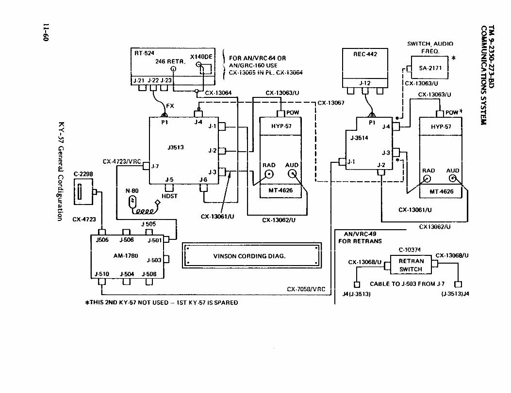
TM 9-2350-273-BD
11-60
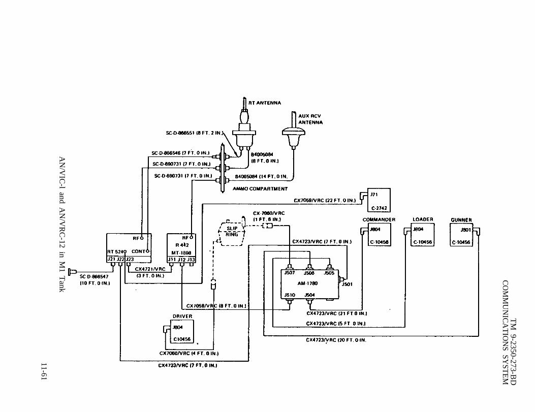
TM
9-2350-273-BD
CO
MM
UN
ICA
TIO
NS SY
STE
M
AN
/VIC
-l and AN
/VR
C-12 in M
1 Tank
11-61
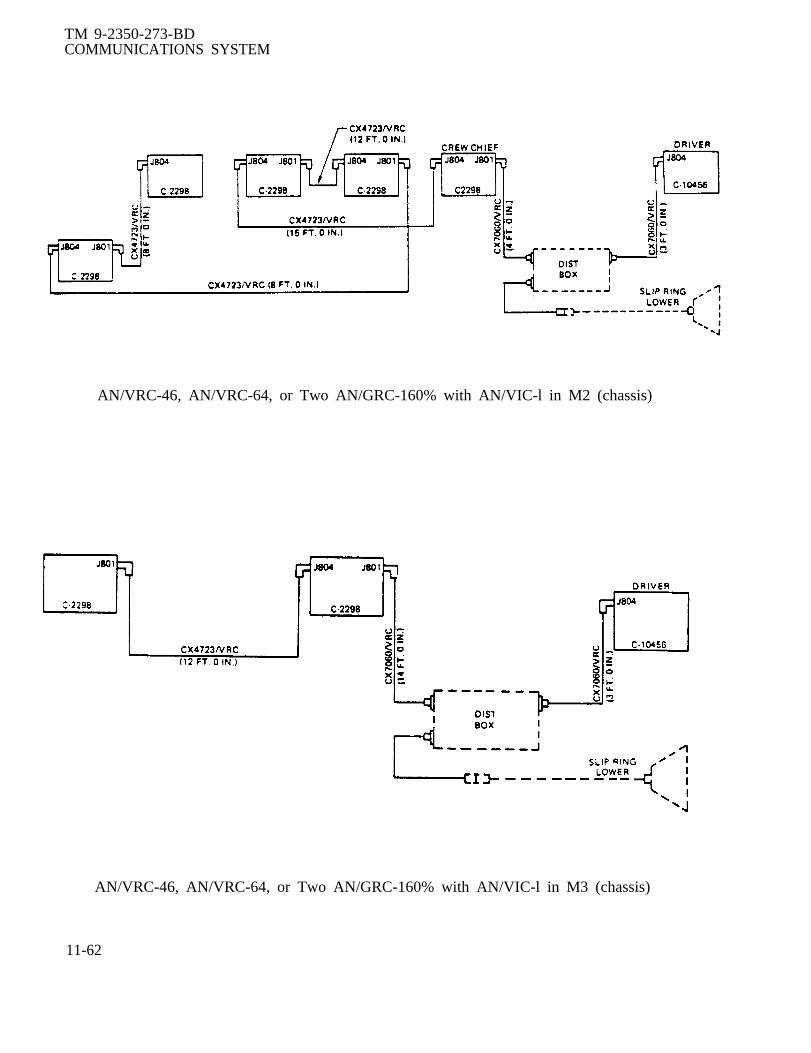
TM 9-2350-273-BDCOMMUNICATIONS SYSTEM
AN/VRC-46, AN/VRC-64, or Two AN/GRC-160% with AN/VIC-l in M2 (chassis)
AN/VRC-46, AN/VRC-64, or Two AN/GRC-160% with AN/VIC-l in M3 (chassis)
11-62
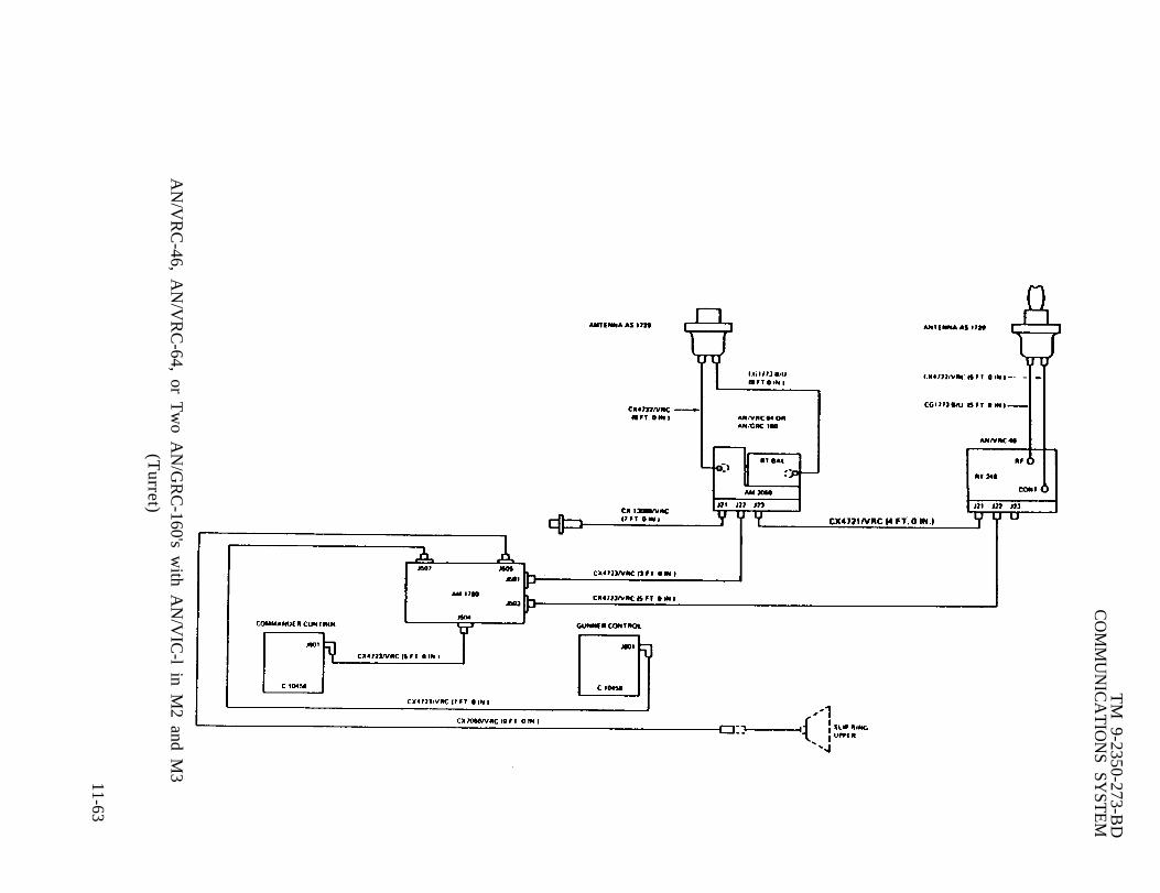
TM
9-2350-273-BD
CO
MM
UN
ICA
TIO
NS SY
STE
M
AN
/VR
C-46, A
N/V
RC
-64, or Tw
o AN
/GR
C-160's w
ith AN
/VIC
-l in M2 and M
3(T
urret)
11-63

TM 9-2350-273-BD
11-64

TM 9-2350-273-BD
11-65

TM 9-2350-273-B
11-66
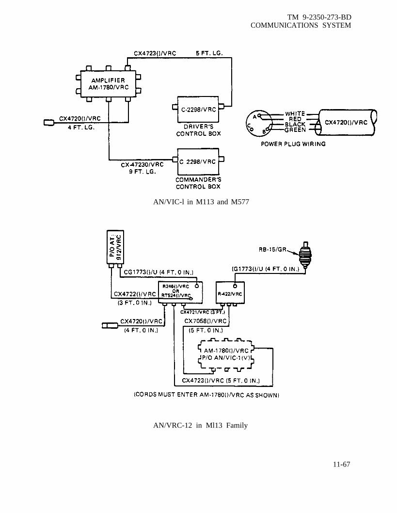
TM 9-2350-273-BDCOMMUNICATIONS SYSTEM
AN/VIC-l in M113 and M577
AN/VRC-12 in Ml13 Family
11-67

TM 9-2350-273-BD
11-68

TM 9-2350-273-BDCOMMUNICATIONS SYSTEM
AN/VIC-l in M109A2 and M109A3
AN/VIC-l in M107 and M110
11-69

TM 9-2350-273-BDCOMMUNICATIONS SYSTEM
AN/VRC-12 in l/4-ton Truck, M151A1
11-70 AN/VIC-1 in Mobile Floating Assault Bridge/Ferry

TM 9-2350-273-BDCOMMUNICATIONS SYSTEM
NOTE: THERE IS A 40 FT. AUDIO EXTENSION CABLE AND RFCABLE BETWEEN THE MX-6707 AND THE R/T.
AN/VRC-12 and AN/VIC-l in AVLB (M60 Chassis)
AN/VRC-12 or AN/VRC-47 in M561
11-71

TM 9-2350-273-BDCOMMUNICATIONS SYSTEM
AN/VIC-l in M561 Commo Vehicle, Radio Sets in Rear
AN/VIC-1 in M561 Commo Vehicle, Radio Sets in Cab
11-72
TM 9-2350-273-BD
A P P E N D I X A
A L T E R N A T E S O U R C E S O F S U P P L Y
BOAR FIXES SHALL BE USED ONLY IN COMBATAT THE DISCRETION OF THE COMMANDER
AND SHALL BE REPAIRED BY STANDARD MAINTENANCE PROCEDURESAS SOON AS PRACTICABLE AFTER THE MISSION IS COMPLETED. b
SECTION I. General.
A-1. General.This appendix lists alternate sources of supply to include foreign ownership of UScombat vehicles, expendable supplies, and spares or repair parts from other systemswhich may be utilized for repairs on the M48/60 tank.
A-1

TM 9-2350-273-BDAPPENDIX A
SECTION II. Foreign Ownership of US Weapons Systems
A-2. General.Repair parts are expected to be in short supply. Parts may be available from othernations involved in the immediate combat areas. Friendly nations owning US weaponssystems may have stocks of repair parts or equipment available for cannibalization.The following tables identify nations owning American combat vehicles.
A-2

TM 9-2350-273-BDAPPENDIX A
Table A-1
North American and Europe
TankM60/M48 M113Family FOV
x
x
Austria
Belgium
Britian
Canada
Denmark
Fed Rep Ger x
Greece x
Italy x
Netherlands
Norway x
Portugal x
Spain x
Turkey x
Switzerland
x
x
x
x
x
x
x
x
x
x
x
S.P.HowM110
x
x
x
x
x
x
x
S.P. S.P. S.P.How How HowM109 M108 M107 Lance
x
x x x
x
x
x
x
x
x
x
x
x
x x x
x
x
x
x
x
x
x
x
A-3

TM 9-2350-273-BDAPPENDIX A
Table A-2Asia
Japan
New Zealand
Pakistan
Philippines
Singapore
South Korea
Taiwan
Thailand
Viet Nam
TankM60/M48Family
x
x
x
x
x
S.P. SOP. S.P. SOP.M113 How How How HowFOV M110 M109 M108 M107 Lance
x
x
x
x
x
x
x
x
x
x x
x x x
x x
A-4

TM 9-2350-273-BDAPPENDIX A
Egypt
Iran
Ethopia
Zaire
Israel x
Jordan x
Kuwait
Lebanon x
Libya
Morocco x
North Yeman x
Oman x
Saudia Arabia x
Sudan x
Tunisia x
TabIe A-3Africa and Middle East
TankM60/M48 M113Family FOV
x x
x x
x
x
x
x
x
x
x
x
x
x
x
x
S.P. S.P. SOP. S.P.How How How HowM11O M109 M108 M107 Lance
x x
x
x
x x
x
x
x
x x
A-5

TM 9-2350-273-BDAPPENDIX A
SECTION III. Expendable Supplies
A-3 General.This appendix lists items recommended for the support of the M 109 Howitzer in acombat environment. The lists include expendable supplies and materials which may beused to expedite BDAR repairs in a combat situation. The items listed may be requiredfor Battlefield Damage Assessment and Repair at maintenance levels from crewthrough DS.
The column marked “Level” indicates the maintenance level at which it is recommendedthese items be stocked or carried. The unit commander may modify the items in thelist and the maintenance levels carrying the items, based on current missionrequirements and recent operational experience.
The items marked “C” (Crew) are recommended to be carried on the vehicle for use incombat emergencies at the discretion of the unit commander. Those items marked“MT” are recommenced to be carried be each Battlefield Damage Assessment and RepairMaintenance Team (MT). Some of these items may already be available atorganizational maintenance, however, additional items will be required to stock eachMT. Those items marked “O” are recommended to be stocked at organizational leveland those marked “MST” are recommended to be carried by the DS Maintenance SupportTeam (MsT).
A-6

TM 9-2350-273-BDAPPENDIX A
ITEMNUMBER LEVEL
1
2
3
4
5
6
7
8
9
10
11
12
13
14
15
0
0
0
MT
c
c
c
c
MT
MT
o
0
c
c
o
EXPENDABLE SUPPLIES
NSN DESCRIPTION
8040-00-831-3403 Adhesive, epoxy 1 pt
8040-00-828-7385 Adhesive/Sealant, siliconerubber, GE RTV 103
8040-00-738-6429 Adhesive, epoxy
5999-00-661-0416 Cap, electrical: crimp style
8030-00-159-5032 Cement, epoxy, devcon F-2
4730-00-289-5909 Clamp, hose: 3/8 in. to 1 in.
4730-00-908-3193 Clamp, hose: 1 1/16 in. to2 in.
5350-00-192-5047 Cloth, abrasive: al-oxide1/09 in. w, 11 in. lg (50sheets)
5315-00-598-5916 Cotter pin assortment
5940-00-296-5326 Ferrule, electrical:wristlock type 22-14 wire size
U/I
kt
tu
kt
pkg
kt
ea
ea
pkg
At
(10 in pkg) pkg
5330-00-291-1605 Gasket, cork, 1/32 in. sh
5330-00-171-9134 Gasket, cork, 3/16 in. sh
5330-00-467-3615 Gasket, material, 1/32 in.(w.o.g. resistant) sh
5330-00-223-5845 Gasket, material, 1/64 in.(w.o.g. resistant) sh
5330-00-467-3615 Gasket, material, 1/32 in.(w.o.g. resistant) sh
A-7

TM 9-2350-273-BDAPPENDIX A
EXPENDABLE SUPPLIES AND MATERIALS - Continued
ITEMNUMBER
16
17
18
19
20
21
22
23
24
25
26
27
28
29
30
A-8
LEVEL
o
0
0
0
0
MT
o
0
c
MT
MT
MT
MT
MT
o
NSN
4720-00-62 >-9178
4720-00-169-5112
4720-00-288-9873
8010-00-515-2487
5310-00-297-3751
5330-00-966-8657
9650-00-26&5050
5410-00-793-2021
4020-00-968-1352
5320-01-004-0238
5320-01-028-6621
5320-00-510-7823
5320-00-408-6073
8030-00-656-1426
533-00-054-5273
DESCRIPTION
Hose, non-metallic, 1/4 in. ID
Hose, non-metallic, 1/2 in. ID
Hose, non-metallic, 3/4 in. ID
Lacquer, insulating,electrical
Nut Assortment
Packing Assortment (O-rings)
Pig Lead, 5 lb
Repair Kit, electronicequipment shelter(fiberglass)
Rope, polypropylene(600 ft roll)
Rivet, pop, steel, SB4-2,1/8 in. dia 1/8 in. lg(quantity 100)
Rivet, pop, steel, SB4-4,1/4 in. dia 1/4 in. lg(quantity 50)
Rivet, pop, aluminum,AB4-2A 1/8 in. dia 1/8
Rivet, pop, aluminum,
in. lg
AB6-2A 3/16 in. dia 1/8 in. lg
Sealing Compound, gasket,non-hardening
Screen Wire Mesh60 in. x 150 ft
u / I
f t
f t
f t
pt
a t
ea
lb
ea
roll
hd
ea
hd
pt
roll

ITEMNUMBER
31
32
33
34
35
36
37
38
39
40
41
42
43
44
45
46
TM 9-2350-273-BDAPPENDIX A
EXPENDABLE SUPPLIES AND MATERIALS - Continued
LEVEL
o
0
0
MT
MT
MT
c
MT
c
c
MT
c
MT
MT
MT
MT
NSN
8030-00-935-1083
8030-00-965-2004
8030-00-881-5238
5305-00-275-4073
5940-00-840-0139
5940-00-500-8723
5975-00-451-5001
5820-00-783-9035
9905-000-537-8957
8030-00-889-3535
5970-00-543-1005
7510-00-802-8311
5940-00813-0698
5940-00-577-3711
5940-00-283-5280
5940-00-143-4780
DESCRIPTION U/I
Sealant, asphalt base, 8-lb can
Sealant, synthetic rubber1 pt kt
Sealant and Puttying CompoundKit: kit no. 3 qt
Set Screw Assortment
Splice, conductor: crimpstyle, wire size 10
Splice, conductor: crimpstyle, wire size 10
Strap, tiedown (nlyon)
Strap, clamp, perforated
Tag, blank, white
Tape, anti-seizing pipeplug, teflon, 1/2 in. wide
Tape, electrical
Tape, filament-reinforced:3/4 in., 50 yd roll
Terminal, lug: crimp style,stud sz 6, wire SZ, 22-18
Terminal, lug: crimp stylestud sz 10, wire sz 22-18
Terminal, lug: crimp style,stud sz 6, wire sz 16-14
Terminal, lug: crimp stylestud sz 10, wire sz 16-14
kt
a t
ea
ea
hd
f t
bd
ea
roll
roll
ea
hd
e a
ea
A-9

TM 9-2350-273-BDAPPENDIX A
EXPENDABLE SUPPLIES AND MATERIALS - Continued
ITEMNUMBER
47
48
A-8
49
50
51
52
53
54
55
56
57
58
LEVEL
MT
MT
Mt
MT
MT
MT
MT
MT
MT
c
c
MT
NSN
5940-00-143-4794
5940-00-804-9185
5940-00-804-9184
5970--00-815-1295
5970-00-812-2967
5970-00-812-2968
5970-00-812-2969
5310-00-209-2312
5310-00-275-4290
6145-00-152-6499
6145-00-435-8613
5315-00-271-4251
DESCRIPTION
Terminal, lug: crimp style,stud sz 10, unspec
Terminal, quick disconnect,wire sz 18
Terminal, quick disconnect,wire sz 14-16
Tubing, shrink, 1/4 in.
Tubing, shrink, 1 in.
Tubing, shrink, 1/6 in.
Tubing, shrink, 1/8 in.
Washer, lock, assortment
Washer, flat, assortment
Wire, wire sz 14
Wire, wire size 18
Woodruff Key Assortment
u / I
ea
pkg
pr
f t
f t
f t
f t
a t
a t
f t
f t
a t
A-10

TM 9-2350-273-BDAPPENDIX A
SECTION IV. Interchangeability Parts With Same NSN
A-4 General.
This section lists and cross-references by National Stock Number (NSN) and nameweapon systems having these parts. Parts pertaining to the turret are listed in tableA-4. Parts pertaining to the hull are listed in table A-5.
A-11

TM 9-2350-273-BD
A-12
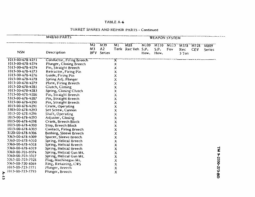
A-13
TM 9-2350-273-BD

A-14
TM 9-2350-273-BD
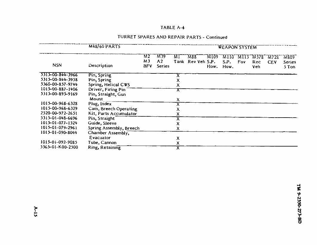
TM 9-2350-273-BD
A-15


TM
9-2350-273-BD
A-17
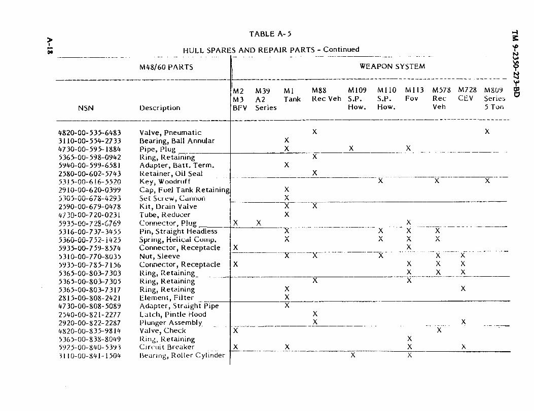
A-18
TM 9-2350-273-BD

TM 9-2350-273-BDA-19 (A-20 blank)


TM 9-2350-273-BD
A P P E N D I X B
SPECIAL AND FABRICATED TOOLS
BDAR FIXES SHALL BE USED ONLY IN COMBATAT THE DISCRETION OF THE COMMANDER
AND SHALL BE REPAIRED BY STANDARD MAINTENANCE PROCEDURESAS SOON AS PRACTICABLE AFTER THE MISSION IS COMPLETED.
SECTION I. General
B-1. General.
This appendix lists items recommended for the support of the vehicle in a combatenvironment. The items listed may be required for Battlefield Damage Assessment andRepair at maintenance levels from crew through DS. Also listed are expedient tools forperforming BDAR repairs using non-standard equipment.
B-1

TM 9-2350-273-BDAPPENDIX B
SECTION II. Tools
B-2. General.
Tools listed in this appendix will enhance crew members and mechanics at all levels toaccomplish Battlefield Damage and Assessment repairs in a more expedient manner.Some tools listed may already be on hand in the unit.
The column marked "Level” indicates the maintenance level at which it is recommendedthese items be stocked or carried. The unit commander may modify the items in thelist and the maintenance levels carrying the items, based on current missionrequirements and recent operational experience.
The items marked “C” (Crew) are recommended to be carried on the vehicle for use incombat emergencies at the discretion of the unit commander. Those items marked“MT” are recommended to be carried by each Battlefield Damage Assessment andRepair Maintenance Team (MT). Some of these items may already be available atorganizational maintenance, however, additional items will be required to stock eachMT. Those items marked “O” are recommended to be stocked at organizational andthose marked “MST” are recommended to be carried by the DS maintenance supportteams (MsT).
B-2

TM 9-2350-273-BDAPPENDIX B
SECTION II. Tools
TOOLS
ITEMNUMBER
1
2
3
4
5
6
7
8
9
10
11
12
13
14
15
16
LEVEL
c
c
MT
MT
MT
c
c
c
c
o
c
c
c
c
c
c
NSN
5110-00-277-4591
5110-00-927-1063
5120-00-203-6431
5120-00-278-2423
5120-00-278-6520
5120-00-227-8074
5110-00-241-91535110-00-241-9156
5110-00-234-6559
5110-00-289-9657
4940-00-561-1002
5110-00-263-0349
5110-00-240-5943
5120-00-221--1536
5120-00-239-8251
5120-00-247-5177
DESCRIPTION
Blade, hand hancksaw: 24 teethper in., 10 in.
Blade, hacksaw, flat (tungsten)
Clamp, C: 6 in. (2 required)
Crimping Tool: terminal, handw/cutting pin, stripper
Cutter, tubing, close quarters
Extension, socket wrench: 1/2 in.sq dr 10 in. lg
File, hand half rnd 10 in.
File, hard rnd style
Frame, hand hacksaw, 10 in. and12 in. blade accommodated
Gun, thermal: PN 8031088
Handle, file
Knife, pocket: w/clevis,screwdriver, wire scraper andcutting blade
Knife, putty
Lifter, roadwheel arm
Pliers: linemans w/side cutter,8 in.
Pliers: Irnd nose w/cutter, 6 in.
B-3
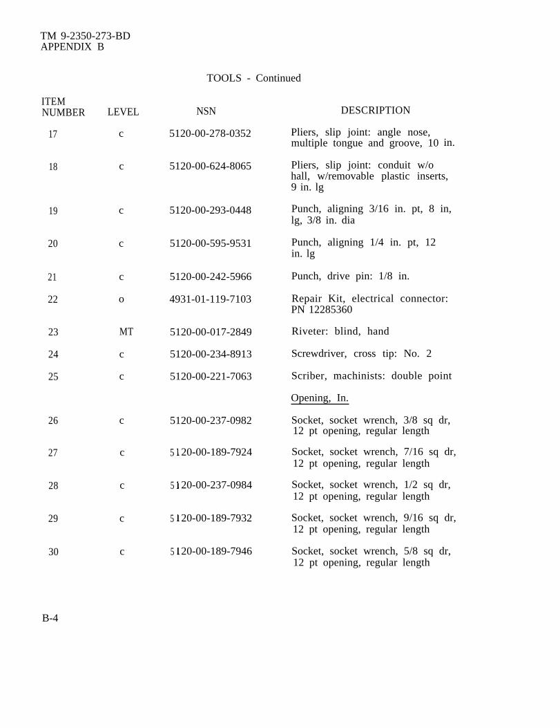
TM 9-2350-273-BDAPPENDIX B
TOOLS - Continued
ITEMNUMBER LEVEL NSN
17 c 5120-00-278-0352
18 c 5120-00-624-8065
19
20
21
22
23
24
25
26
27
28
29
30
c
c
c
o
MT
c
c
c
c
c
c
c
5120-00-293-0448
5120-00-595-9531
5120-00-242-5966
4931-01-119-7103
5120-00-017-2849
5120-00-234-8913
5120-00-221-7063
5120-00-237-0982
5
5
5
5
20-00-189-7924
20-00-237-0984
20-00-189-7932
20-00-189-7946
DESCRIPTION
Pliers, slip joint: angle nose,multiple tongue and groove, 10
Pliers, slip joint: conduit w/o
in.
hall, w/removable plastic inserts,9 in. lg
Punch, aligning 3/16 in. pt, 8 in,lg, 3/8 in. dia
Punch, aligning 1/4 in. pt, 12in. lg
Punch, drive pin: 1/8 in.
Repair Kit, electrical connector:PN 12285360
Riveter: blind, hand
Screwdriver, cross tip: No. 2
Scriber, machinists: double point
Opening, In.
Socket, socket wrench, 3/8 sq dr,12 pt opening, regular length
Socket, socket wrench, 7/16 sq dr,12 pt opening, regular length
Socket, socket wrench, 1/2 sq dr,12 pt opening, regular length
Socket, socket wrench, 9/16 sq dr,12 pt opening, regular length
Socket, socket wrench, 5/8 sq dr,12 pt opening, regular length
B-4

ITEMNUMBER LEVEL
31
32
33
34
35
36
37
38
39
40
41
42
43
44
c
c
c
c
c
c
c
MT
MT
c
MT
c
c
c
TM 9-2350-273-BDAPPENDIX B
TOOLS - Continued
NSN
5120-00-235-5870
5120-00-189-7985
5120-00-189-7933
5120-00-189-7934
5120-00-189-7935
5120-00-189-7927
5120-00-242-3349
5110-00-803-6339
6625-01-102-6878
5140-00-498-8772
5120-01-128-5511
5120-01-121-4981
5120-00-240-5328
DESCRIPTION
Opening, In. - Continued
Socket, socket wrench, 11/16 sq dr,12 pt opening, regular length
Socket, socket wrench, 3/4 sq dr,12 pt opening, regular length
Socket, socket wrench, 13/16 sq dr,12 pt opening, regular length
Socket, socket wrench, 7/8 sq dr,12 pt opening, regular length
Socket, socket wrench, 15/ 16 sq dr,12 pt opening, regular length
Socket, socket wrench, 1 sq dr,12 pt opening, regular length
Socket, deepwell, 1/2 in. dr,3/4 in.
Splitting Tool, nut, 7/8 in. cap
TA-1 Continuity and Test ProbeKit: PN 12303622
Tool Box, portable: steelw/removable tray 21 in. lg,8-1/2 in. w, 7-3/8 in. h
Tool Set, supplement,organizational: PN 12310894
Web Strap Assembly, adjustable:PN 12273481
Wrench, plug, sraight bar hex:PN 12284998
Wrench, adjustable: 8 in.
B-5

TM 9-2350-273-BDAPPENDIX B
TOOLS - ContinuedITEMNUMBER LEVEL NSN DESCRIPTION
Opening, In. - Continued
45 c 5120-00-277-4244 Wrench, plier: straight jaw,8-1/2 in.
46 c 5120-00-148-7917 Wrench Set, combination box withopen end, 12 components, 5/16 in.- 1 in.
47 c 5120-00-148-7918 Wrench Set, open end, fixed, 6components 3/16 in. - 1-1/ 16 in.
B-6

TM 9-2350-273-BDAPPENDIX B
SECTION III. Test Equipment
B-3. FIELD EXPEDIENT TEST EQUIPMENT
General InformationSometimes, in the process of assessing the battlefield damage, it is necessary to makevoltage and resistance measurements to determine where the fault is. Standard testequipment (voltmeter, ohmmeter, SWR meter, etc.) should be used whenever possible.If standard test equipment is not available, field expedient equipment can be fabricatedusing parts commonly found on the vehicle and in the forward maintenance areas. Thefollowing paragraph provides fabrication instructions for making a voltmeter,ohmmeter, and RF transmitter output tester.
NOTE
Accurate measurements are not available. These are Go - No-Go meters.
1. Making a Voltmeter.
A voltmeter can be madefrom a light bulb and two pieces of wire.The pieces of wire can be connected tothe case and center terminal of thebulb by means of solder, twisting, orsimply holding the wire ends againstthe bulb (see illustration). The voltagerating of the bulb should be close tothe value of the expected voltage beingmeasured. For voltages in the 18 to 30vdc range, any light bulb on the driver’smaster panel, driver’s instrument panel,gunner’s panel, commander’s panel, orgunner’s primary sight can be used. Forvoltages of 5 vdc or less a two-batterycell flashlight bulb can be used. Thepresence of voltage will cause the bulb toglow. Polarity of dc voltage does not haveto be observed; even ac voltage can be measured.Twist exposed wire ends together and applysolder, if available, and solder. Touch tovoltage source when ready to make measurement.
B-7
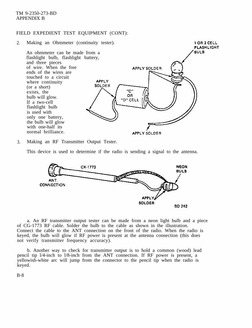
TM 9-2350-273-BDAPPENDIX B
FIELD EXPEDIENT TEST EQUIPMENT (CONT):
2. Making an Ohmmeter (continuity tester).
An ohmmeter can be made from aflashlight bulb, flashlight battery,and three piecesof wire. When the freeends of the wires aretouched to a circuitwhere continuity(or a short)exists, thebulb will glow.If a two-cellflashlight bulbis used withonly one battery,the bulb will glowwith one-half itsnormal brilliance.
3. Making an RF Transmitter Output Tester.
This device is used to determine if the radio is sending a signal to the antenna.
a. An RF transmitter output tester can be made from a neon light bulb and a pieceof CG-1773 RF cable. Solder the bulb to the cable as shown in the illustration.Connect the cable to the ANT connection on the front of the radio. When the radio iskeyed, the bulb will glow if RF power is present at the antenna connection (this doesnot verify transmitter frequency accuracy).
b. Another way to check for transmitter output is to hold a common (wood) leadpencil tip l/4-inch to l/8-inch from the ANT connection. If RF power is present, ayellowish-white arc will jump from the connector to the pencil tip when the radio iskeyed.
B-8

TM 9-2350-273-BDAPPENDIX B
SECTION IV. Welding Expedients
B-4. CONTROLLED AMPERAGE
General InformationBattlefield repairs requiring welding can be done by using the auxiliary generator (LittleJoe) from the M88 or generator recovery vehicle if a regular welder is not available.
Limitations● Possible degraded armor protection
Materials/Tools:● Auxiliary generator (24 vdc)● Control unit from a welder or similar control● Welders helmet and gloves● Welding rod, coat hangers, or barbed wire● Heavy gauge cable (2.0 gauge or larger)● Vise grips or clamps● Fuel line
Personnel/Time Required● 2 soldier● 1-2 hours
Other Options:● Use uncontrolled amperage● Weld using vehicle battery power
Procedural Steps:
1. Remove auxiliary generator from M88 recovery vehicle and place close to area to bewelded. Connect heavy gauge cables to (+) and (-) output posts. Also connect controlunit to (+) and (-) output posts. Tighten terminal securely.
2. Connect negative (-) cable to tank hull with clamp close to area to be welded.Connect welding rod to positive (+) cable with vise grips. Insulate vise grips withgloves, rags, or several layers of dry paper.
WARNING
Use welder's helmet to protect eyes and face from arc. Do nottouch exposed cable or vise grips with bare hands; metalgets very hot. Do not perform this task in rain or on wet groundbecause of electrical shock hazard.
B-9

TM 9-2350-273-BDAPPENDIX B
Procedural Steps (Cent}
3. Start auxiliary generator, strike arc, and weld. Set control unit for amperage levelrequired by the thickness of the metal.
4. Record the BDAR action taken. When the mission is completed, as soon aspracticable, repair vehicle using standard maintenance procedures.
B-5. UNCONTROLLED AMPERAGE
General Information:Battlefield repairs requiring welding can be accomplished by using auxiliary generator(Little Joe) from M88 recovery vehicle or a generator if a regular welder is notavailable. Welding will be difficult without amperage control.
Limitations:● Possible degraded armor protection
Personnel/Time Required● 2 soldiers● 1-3 hours
Materials/Tools● Auxiliary generator (24 vdc)● Heavy gauge cable (2.0 gauge minimum)● Vise grips or clamps● Fuel line● Welder helmet and gloves● Welding rod, coat hangers, or barbed wire
Other Options:● Weld using the vehicle battery power
Procedural Steps
1. Remove auxiliary generator from M88 recovery vehicle and place close to area to bewelded. Connect heavy gauge cables (+) and (-) output posts and tighten securely.
2. Connect negative (-) cable to vehicle hull with clamp close to area to be welded.Connect welding rod to positive (+) cable with vise grip and insulate area against heatwith gloves, rags, or several layers of dry paper.
B-lo

TM 9-2350-273-BDAPPENDIX B
Procedural Steps (Cont):WARNING
Use welder's helmet to protect eyes and face from arc. Do not touch exposedcable or vise grips with bare hands; metal will get very hot. Do not performthis task in rain or on wet ground because of possible electric shock.
3. Start auxiliary generator, strike arc, and weld. Use small diameter welding rod forthin metal; use large welding rod for thick metal. Continue to weld until repair issatisfactory.
4. Record the BDAR action taken. When the mission is completed, as soon aspracticable, repair vehicle using standard maintenance procedures.
SECTION V. Containers
B-6. IMPROVISED CONTAINER
General InformationMany repairs require the draining of the fluid systems (fuel, coolants, or oils). Animprovised container can be used to catch the fluids.
Limitations:● None
Personnel/Time Required:● 2 soldiers● 20-30 minutes
Materials/Tools:● Large plastic sheet● Poncho● Tarpalin
Procedural Step
1. Dig a basin large enough to hold liquid.
2. Line the hole with a liner to hold the fluids.
3. Drive the vehicle over the hole.
4. Drain the liquid.
5. Dip the liquid from the hole using a steel helmet, can or canteen cup.
6. Record the BDAR action taken. When the mission is completed, as soon aspracticable, repair the vehicle using standard maintenance procedures.
B-11(B-12 blank)

TM 9-2350-273-BDAPPENDIX C
A P P E N D I X C
P O L S U B S T I T U T E S
BDAR FIXES SHALL BE USED ONLY IN COMBATAT THE DISCRETION OF THE COMMANDER
AND SHALL BE REPAIRED BY STANDARD MAINTENANCE PROCEDURESAS SOON AS PRACTICABLE AFTER THE MISSION IS COMPLETED.
APPENDIX C
PETROLEUM, OIL AND LUBRICANT (POL) SUBSTITUTES FOR DIESEL ENGINES
SECTION I. General
C-1. General.
a. POL products available within the US and NATO military supply systems,commercial products and, captured products may be acceptable substitutes for POLshortages. Some POL will be destructive if used. This appendix provides tables on howto blend or mix good fuels with poor or non-fuels to increase the available quantity offuel. This appendix also presents information on lubricants and hydraulic fluids. Thetables divide POL products into three categories as follows:
Primary. The correct product for the system.
Alternate. A product that closely matches the primary but will result inreduced performance. Using the alternate POL will have no effect on the durability ofthe system. There are no restrictions on the duration of use.
Emergency or Expedient. A product that can be used for a short period oftime only. These products are a last resort only and will result in a significantreduction in performance and in serious harm to the system with continued use.
b. POL products are usually identified by NSNs or part numbers which identifythe product, however, specification numbers and product names may also be a means ofidentifying the product. Guidance provided is keyed to specification numbers, productnames, application (automotive, aviation, marine), and the type of user (military,commercial and foreign).
c. NATO products can usually be assumed to be direct replacements for USMilitary products, but there are some products which do not meet the same userapplications. The American Society of Testing and Measurements (ASTM)specifications relate to commercial products found in the US.
d. This section will list a few elementary characteristics of importance, althoughyou will have no means of measuring or predicting them. You can use the basic fuels,as provided, in order or priority. It will tell you how to mix one or more fluids toproduce a usable fuel and finally tell how to remove or flush a fuel from the system.
C-1

TM 9-2350-273-BDAPPENDIX C
e. Table C-1 identifies fuels or products that can be used as fuels. One of thebest means to increase the available fuel is to use potential substitutes as extenders bymixing them with the primary fuels and not using them as the sole fuel source. Thisallows some products which could not ordinarily be burned (or pumped) to be used bydiluting them. Because of the dangers of varying combustibility of fuels, increased byvaporization during filling, the blending process is very important. The most direct andexpedient procedure to mix fuels is to add the two fuels at the same time from twoseparate fuel lines. If added directly to the vehicle fuel tanks as separate fuels there isnot sufficient turbulence in filling or shaking by normal driving to provide a properlymixed fuel. In vehicles with more than one tank, you could end up with a distinct fueltype in each tank.
C-2. FUEL BLENDING.
a. In following the blending procedure it must be remembered that the basic fuelis the better of the two fuels and the extender is the poorer. The blending fuel is theextender. While you can use up to 50 percent (half and half) of the extender you shouldnot use more than is needed to obtain the supply needed. Also, ensure a fuel tank orcontainer is available to hold the quantity of fuel needed to perform the mixingoperation.
b. Blending Procedure. The preferred location to accomplish blending is at a fueldispensing site or in fuel dispensing vehicles that utilize their own pumps. The leastdesirable is using vehicle’s fuel tanks. Blending in vehicle fuel tanks should only be doneas a last resort because it is imprecise and time consuming.
(1) Blending in Fuel Dispensing Vehicles. Add the blending fuel to the fueltank and mix by reconnecting the pump inlet hose to the vehicle and recirculating thefuel for a minimum of 15 minutes.
(2) B1ending in 55 Gallon Drums. Add the blending fuel directly into a drumand mix by rolling the drum.
(3) B1ending in Gravity Feed Tanks (Stationary) Not Equipped With FuelTransfer Pumps. Blending fuel can be added manually or by using the pump and meterof a fuel dispensing vehicle. Add the blending fuel and mix by recirculating from thetank outlet to the tank truck pump inlet.
NOTE
Blending in the fuel tanks of using equipment and vehicles should beundertaken only as a last resort. Add both fuels to the fuel tankat the same time with dual nozzles, or from fuel cans.
c. If expedient fuels are not used completely during the operation, they should bedrained or pumped out. Fill the vehicle fuel tanks with 10-15 gallons of an approvedprimary fuel and run the engine for at least 1/2 hour. Operate the engine under a loador drive the vehicle a sufficient distance to bring the engine up to operatingtemperature.
C-2
TM 9-2350-273-BDAPPENDIX C
C-3. LUBRICANTS AND HYDRAULIC FLUIDS.
This section lists a few elementary characteristics of importance although thereare no expedient means of measuring or predicting them. A list of basic fluids whichcan be used is provided in order or priority. Cautions on incompatible fluids arementioned and a means suggested to flush the system.
b. Table C-2 provides a list of basic fluids which can be used as substitutes(alternate and expedient). It is structured around the vehicle lube order. Alternateproducts shown are NATO equivalents to the US specifications and can really beconsidered primary fluids. There are no corresponding ASTM designators. Theexpedients are emergency only substitutions. They may cause one of three problemseither individually or in combination.
(1) They may not allow proper or efficient operations because of improperviscosity.
(2) They may cause high wear rate because of improper viscosity.
(3) They may cause seal damage or create deposits because of improper chemicalcomposition.
c. There are no established time constraints on these expedients but the shorterthe time used the better.
C-4. FLUSHING LUBRICANT AND HYDRAULIC SYSTEMS.
a. Expedient lubricant and hydraulic fluids must be removed as soon as possible,and the system cleaned and inspected.
b. For those systems using oils, flushing involves draining, refilling with theproper product, operating to insure complete circulation and when possible stableoperating temperature (this usually means at least 1/2 hour), a redrain and refill. Forthe transmission and hydraulic system a second period of operations and a third drainand refill are needed. Installation of new filters is desirable. Filters must as aminimum be removed and cleaned. As a last resort only, operate without filters. Whilesystems should not be disassembled to inspect seals, maintenance organizations shouldbe prepared to replace seals that show signs of leaking. Organizations must observeseals on these systems during subsequent operations.
c. For systems using grease, it is normally necessary to disassemble the systemand wash the parts, especially the bearings, in a suitable solvent. The parts are thenwiped dry, inspected for wear and pitting, replaced if needed and repacked with theproper product.
C-3

TM 9-2350-273-BDAPPENDIX C
Section II. Tables
TABLE C-1. FUELS AND SUBSTITUTE FUELS
(Listed in Order of Priority)
Primary Fuels
1. VV-F-800 (Diesel Fuels) (DF-1, DF-2, DF-A)2. NATO-F-54 (Diesel Fuel, Military)3. ASTM-D-975 (Automotive Diesel) (l-D & 2-D)4. NATO -58 (Kerosene)5. ASTM-D3699 (Kerosene)6. Any blend of the above.
Alternate Fuels
1.2.3.4.5.6.7.8.9.10.11.12.13.
MIL-T-5624 (Aviation Turbine Fuel) (JP-4 & JP-5)*NATO-F-40 (Avaiation Turbine Fuel)ASTM-D-1655 (Aviation Turbine Fuel) (Jet B)NATO-F-44 (Aviation Turbine Fuel)MIL-T-83133 (Avaition Turbine Fuel) (JP-4)NATO-F-34 (Aviation Turbine Fuel)ASTM-D-1655 (Aviation Turbine) (Jet A-1)ASTM-D-2880 (Turbine Fuel) (0-GT, 1-GT, 2-GT, 3-GT, 4-GT)MIL-F-16884 (Marine Diesel) (DFM)NATO-F-76 (Navy Distilate Fuel)MIL-F-815 (Navy Distilate) (FO-1 & FO-2)NATO-F-75 (Navy Distilate) (Low Pour Point)ASTM-D-396 (Fuel Oil) (No. 1 & 2)
With Fuel Extenders (Blends up to half and half -50 percent extender)
Base Extender
14. Any Primary Fuel15. Any Alternate Fuel
Any Alternate Fuel
16.Any Alternate Fuel
MIL-F-815 Any lighter primary or alternate17. NATO-F-76 Any lighter primary or alternate18. Any Diesel Fuel PD-680 (Type I & II) (Dry Cleaning
Solvent)ASTM-D-484 (K, I, II, III, IV) (D.C.S.)ASTM-D-235 (I thru IV) (Pet. Spirits)
*Better than a 50 percent chance these will have acceptable cetane.
C-4
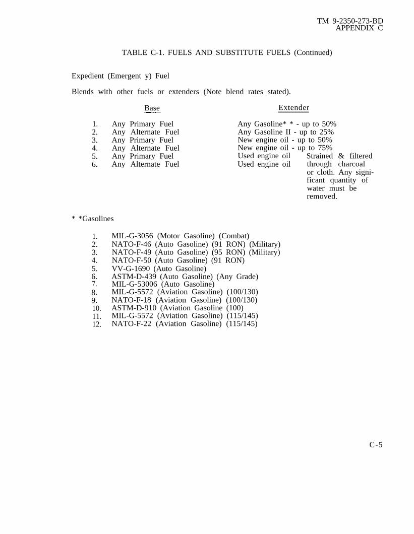
TM 9-2350-273-BDAPPENDIX C
TABLE C-1. FUELS AND SUBSTITUTE FUELS (Continued)
Expedient (Emergent y) Fuel
Blends with other fuels or extenders (Note blend rates stated).
Base Extender
1. Any Primary Fuel Any Gasoline* * - up to 50%2. Any Alternate Fuel Any Gasoline II - up to 25%3. Any Primary Fuel New engine oil - up to 50%4. Any Alternate Fuel New engine oil - up to 75%5. Any Primary Fuel Used engine oil Strained & filtered6. Any Alternate Fuel Used engine oil through charcoal
or cloth. Any signi-ficant quantity ofwater must beremoved.
* *Gasolines
1.2.3.4.5.6.
8.9.10.11.12.
MIL-G-3056 (Motor Gasoline) (Combat)NATO-F-46 (Auto Gasoline) (91 RON) (Military)NATO-F-49 (Auto Gasoline) (95 RON) (Military)NATO-F-50 (Auto Gasoline) (91 RON)VV-G-1690 (Auto Gasoline)ASTM-D-439 (Auto Gasoline) (Any Grade)MIL-G-53006 (Auto Gasoline)MIL-G-5572 (Aviation Gasoline) (100/130)NATO-F-18 (Aviation Gasoline) (100/130)ASTM-D-910 (Aviation Gasoline (100)MIL-G-5572 (Aviation Gasoline) (115/145)NATO-F-22 (Aviation Gasoline) (115/145)
C-5
7.

TM 9-2350-273-BD
C-6

TM 9-2350-273-BDC-7 (C-8 blank)


TM 9-2350-273-BDAPPENDIX D
APPENDIX D
Not Used
Change 1D-l(D-2 blank)

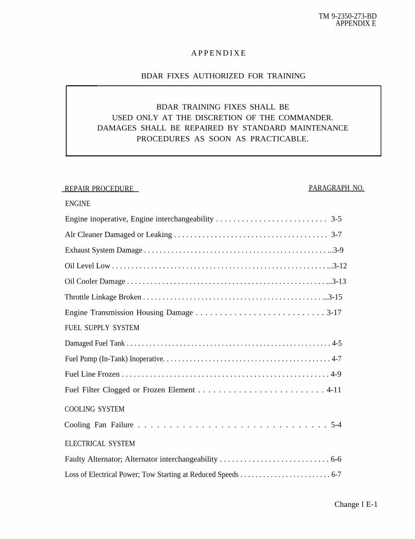
TM 9-2350-273-BDAPPENDIX E
A P P E N D I X E
BDAR FIXES AUTHORIZED FOR TRAINING
BDAR TRAINING FIXES SHALL BEUSED ONLY AT THE DISCRETION OF THE COMMANDER.
DAMAGES SHALL BE REPAIRED BY STANDARD MAINTENANCEPROCEDURES AS SOON AS PRACTICABLE.
REPAIR PROCEDURE PARAGRAPH NO.
ENGINE
Engine inoperative, Engine interchangeability . . . . . . . . . . . . . . . . . . . . . . . . . . 3-5
Alr Cleaner Damaged or Leaking . . . . . . . . . . . . . . . . . . . . . . . . . . . . . . . . . . . . . . 3-7
Exhaust System Damage . . . . . . . . . . . . . . . . . . . . . . . . . . . . . . . . . . . . . . . . . . . . . . . ...3-9
Oil Level Low . . . . . . . . . . . . . . . . . . . . . . . . . . . . . . . . . . . . . . . . . . . . . . . . . . . . . . . ...3-12
Oil Cooler Damage . . . . . . . . . . . . . . . . . . . . . . . . . . . . . . . . . . . . . . . . . . . . . . . . . . . ...3-13
Throttle Linkage Broken . . . . . . . . . . . . . . . . . . . . . . . . . . . . . . . . . . . . . . . . . . . . . . ...3-15
Engine Transmission Housing Damage . . . . . . . . . . . . . . . . . . . . . . . . . . . 3-17
FUEL SUPPLY SYSTEM
Damaged Fuel Tank . . . . . . . . . . . . . . . . . . . . . . . . . . . . . . . . . . . . . . . . . . . . . . . . . . . . . . 4-5
Fuel Pump (In-Tank) Inoperative. . . . . . . . . . . . . . . . . . . . . . . . . . . . . . . . . . . . . . . . . . . . 4-7
Fuel Line Frozen . . . . . . . . . . . . . . . . . . . . . . . . . . . . . . . . . . . . . . . . . . . . . . . . . . . . 4-9
Fuel Filter Clogged or Frozen Element . . . . . . . . . . . . . . . . . . . . . . . . . 4-11
COOLING SYSTEM
Cooling Fan Failure . . . . . . . . . . . . . . . . . . . . . . . . . . . . . . 5-4
ELECTRICAL SYSTEM
Faulty Alternator; Alternator interchangeability . . . . . . . . . . . . . . . . . . . . . . . . . . . 6-6
Loss of Electrical Power; Tow Starting at Reduced Speeds . . . . . . . . . . . . . . . . . . . . . . . . 6-7
Change l E-1

TM 9-2350-273-BDAPPENDIX E
APPENDIX EBDAR FIXES AUTHORIZED FOR TRAINING (CONT’D)
REPAIR PROCEDURE PARAGRAPH NO.
ELECTRICAL SYSTEM (Continued)
Starter Failure . . . . . . . . . . . . . . . . . . . . . . . . . . . . . . . . . . . . . . . . . . , . . . . . . . . . . . . . ...6-8
Engine Starter Will Not Energize; Defective Neutral Safety Switch . . . . . . . . . . . . . . . ...6-9
Turret; No Hydraulic Power . . . . . . . . . . . . . . . . . . . . . . . . . . . . . . . . . . . . . . . . . . . . ...6-10
SUSPENSION SYSTEM
Track Partially Thrown . . . . . . . . . . . . . . . . . . . . . . . . . . . . . . . . . . . . . . . . . . . . . . . . . . ...9-5
Track Wedge Lost . . . . . . . . . . . . . . . . . . . . . . . . . . . . . . . . . . . . . . . . . . . . . . . . . . . . . ...9-6
Traction Inadequate . . . . . . . . . . . . . . . . . . . . . . . . . . . . . . . . . . . . . . . . . . . . . . . . . . . ...9-8
Drive Sprocket Hub Sheared Off. . . . . . . . . . . . . . . . . . . . . . . . . . . . . . . , . . . . . . . . ...9-10
Support Roller Damaged . . . . . . . . . . . . . . . . . . . . . . . . . . . . . . . . . . . . . . , . . . . . . . . ...9-11
Roadwheel Hub Damage...,.. . . . . . . . . . . . . . . . . . . . . . . . . . . . . . . . . . . . . . . . . ...9-13
Suspension System Positions 2, 3, 4, or 5 Missing or Damaged . . . . . . . 9-15
Compensating IdlerArm Broken.. . . . . . . . . . . . . . . . . . . . . . . . . . . . . . . . . . . . . . . . ...9-16
Suspension System interchangeability . . . . . . . . . . . . . . . . . . . . . . . . . . . . . . . . . . . . ...9-17
Roadwheel Arm Damaged . . . . . . . . . . . . . . . . . . . . . . . . . . . . . . . . . . . . . . . . . . . . . ...9-18
Roadwheel Arm Housing Bolts Sheared . . . . . . . . . . . . . . . . . . . . . . . . . . . . . . . . . . ...9-19
Torsion Bars Bent . . . . . . . . . . . . . . . . . . . . . . . . . . . . . . . . . . . . . . . . . . . . . . . . . . . . ...9-20
Shock Absorbers Defective . . . . . . . . . . . . . . . . . . . . . . . . . . . . . . . . . , . . . . . . . . . . ...9-21
ARMAMENT AND FIRE CONTROL SYSTEM
Gun Tube Unserviceable; Recovery Vehicle Not Available . . . . . . . . . . . . . . . . . . . . ...10-4
Bore Evacuator Damaged . . . . . . . . . . . . . . . . . . . . . . . . . . . . . . . . . . . . . . . . . . . . . ...10-5
Breech Block Will Not Close; Closing Spring Broken . . . . . . . . . . . . . . . . . . . . . . . . . . ..10-6
Gun Does Not Fire; Gun Does Not Return To Battery . . . . . . . . . . . . . . . . . . . . . . . . ...10-7
Gun Will Not Fire; Hard Wire Blasting Machine To Main Gun . . . . . . . . . . . . . . . . . . . . . 10-8
E-2 Change 1

TM 9-2350-273-BDAPPENDIX E
APPENDIX EBDAR FIXES AUTHORIZED FOR TRAINING
REPAIR PROCEDURE PARAGRAPH NO,ARMAMENT AND FIRE CONTROL SYSTEM (Continued)
Main Gun Inoperative; Electrical Powerless . . . . . . . . . . . . . . . . . . . . . . . . . . . . . . . . ...10-9
Turret Interchangeability . . . . . . . . . . . . . . . . . . . . . . . . . . . . . . . . . . . . . . . . . . . . . . . ...10-10
Gun Mount Interchangeability . . . . . . . . . . . . . . . . . . . . . . . . . . . . . . . . . . . . . . . . . . . ...10-11
Gun Tube Interchangeability..,.. . . . . . . . . . . . . . . . . . . . . . . . . . . . . . . . . . . . . . . . ...10-12
Turret PowerPack Damage . . . . . . . . . . . . . . . . . . . . . . . . . . . . . . . . . . . . . . . . . . . . ...10-13
Loaders Safety Switch Failure.. . . . . . . . . . . . . . . . . . . . . . . . . . . . . . . . . . . . . . . . . ...10-14
M85 Gun Inoperative; Powerless . . . . . . . . . . . . . . . . . . . . . . . . . . . . . . . . . . . . . . . ...10-15
Slipring Defective . . . . . . . . . . . . . . . . . . . . . . . . . . . . . . . . . . . . . . . . . . . . . . . . . . . . ...10-16
Turret Power Pack Interchangeability . . . . . . . . . . . . . . . . . . . . . . . . . . . . . . . . . . . . . ...10-17
Manual Pump Fluid Loss . . . . . . . . . . . . . . . . . . . . . . . . . . . . . . . . . . . . . . . . . . . . . . ...10-18
Main Accumulator Damaged . . . . . . . . . . . . . . . . . . . . . . . . . . . . . . . . . . . . . . . . . . . ...10-19
*U.S. GOVERNMENT PRINTING OFFICE: 1990 543-016/40003
Change 1 E-3/(E-4 blank)

TM 9-2350-273-BDINDEX
INDEX
Paragraph,Table Number
Air Cleaner Damaged Or Leaking . . . . . . . . . . . . . . . . . . . . . . . . . . . . . . . 3-7Alternate Sources Of Supply
Expendable Supplies . . . . . . . . . . . . . . . . . . . . . . . . . . . . . . . . . . . . . . . A-3Foreign Ownership Of US Weapons Systems . . . . . . . . . . . . . . . . . . . . . . . A-2Interchangeable Parts, Same NSN . . . . . . . . . . . . . . . . . . . . A-4
Alternator Interchangeability . . . . . . . . . . . . . . . . . . . . . . . 6-6Armament And Fire Control
Assessment Procedure . . . . . . . . . . . . . . . . . . . . . . . . . . . . . . . . . . . . . . . . 10-2BDAR Procedure Index . . . . . . . . . . . . . . . . . . . . . . . . . . . . . . 10-3General . . . . . . . . . . . . . . . . . . . . . . . . . . . . . . . . . . . . . . . . . . . . . 10-1
AssessmentApplication . . . . . . . . . . . . . . . . . . . . . . . . . . . . . . . . . . . . . . . . . . . . . . . . . . . . . . . . . . . . . . . . . . 2-3Process . . . . . . . . . . . . . . . . . . . . . . . . . . . . . . . . . . . . . . . . . . . . . . . . . . . . . . . . . . . . . . . . . . . . . . .. 2-5
Battlefield Damage Assessment/Repair FormsFormsGeneral . . . . . . . . . . . . . . . . . . . . . . . . . . . . . . . . . . . . . . . . . . . . . . . . . . 2-9
BDARApplication . . . . . . . . . . . . . . . . . . . . . . . . . . . . . . . . . . . . . . . . . . . . . . . . . . . . . . . . . . . 1-3Characteristics . . . . . . . . . . . . . . . . . . . . . . . . . . . . . . . . . . . . . . . . . . 1-6Definitions . . . . . . . . . . . . . . . . . . . . . . . . . . . . . . . . . . . . . . . . . 1-4Environment . . . . . . . . . . . . . . . . . . . . . . . . . . . . . . . . . . . . 1-9Permanent . . . . . . . . . . . . . . . . . . . . . . . . . . . . . . 1-11Recommendations And QDR/EIR . . . . . . . . . . . . . . . . . . . 1-5Serviceability And Operability . . . . . . . . . . . . . . . . . . . . . . . . . . 1-10Training . . . . . . . . . . . . . . . . . . . . . . . . . . . . . . . . . . . . 1-7Waiver Of Precautions . . . . . . . . . . . . . . . . . . . . . . . . . . . . . . . . . . . . . . . . . . . . . 1-8
BDAR Procedural IndexAlphabetical . . . . . . . . . . . . . . . . . . . . . . . . . . . . . . . . . . . T2-2Armament And Fire Control . . . . . . . . . . . . . . . . . . . . . . . . 10-2Brakes . . . . . . . . . . . . . . . . . . . . . . . . . . . . . . . . . . . . 8-2Communications Systems . . . . . . . . . . . . . . . .. . . . . . . . . . . . . . . . . . . . . 11-5Cooling System . . . . . . . . . . . . . . . . . . . . . . . . . . . . . . . . . . . . . 5-2Electrical Systems . . . . . . . . . . . . . . . . . . . . . . . . 6-2Engine . . . . . . . . . . . . . . . . . . . . . . . . . . . . . . . . . . . . . 3-2Fuel Supply System . . . . . . . . . . . . . . . . . . . . . . . . . . . . . . . . . . . . . . . . . . . . . . 4-2Powertrain/Steering . . . . . . . . . . . . . . . . . . . . . . . . . . . . . . . . . 7-2Track And Suspension . . . . . . . . . . . . . . . . . . . . . . . . . . 9-2
Index 1

TM 9-2350-273-BDINDEX
Paragraph,Table Number
Brake BDAR, General . . . . . . . . . . . . . . . . . . . . . . . . . . . . . . . . . . . . . . . . . . . . . . . . . . . . . . . . . . . . . . . . . . .8-4Brake Fluid Leakage Of Slave Cylinder . . . . . . . . . . . . . . . . . . . . . . . . . . . . . . . . . . . . . . . . . . ...8.7Brakes
Assessment Procedure . . . . . . . . . . . . . . . . . . . . . . . . . . . . . . . . . . . . . . . . . . . . . . . . . . . . . . . . . . . . . . 8-2BDAR Procedure Index . . . . . . . . . . . . . . . . . . . . . . . . . . . . . . . . . . . . . . . . . . . . . . . . . . . . . . . . . . . . .8-3General . . . . ............... . . . . . . . . . . . . . . . . . . . . . . . . . . . . 8-1
Brakes Locked, Linkage Jammed . . . . . . . . . . . . . . . . . . . . . . . . . . . . . . 8-6Brake Master Cylinder Failure . . .. . . . . . . . . . . . . . . . . . . . . . . . . . . . . . 8-5Breech Block Will Not Close, Closing Spring Broken ..... . . . . . . . . 10-6Bore Evacuator Damaged . . . . . . . . . . . . . . . . . . . . . . . . . . . . . . . . . . . . . . . . . . . . . . . . . . . . . . . . . . . . 10-5
Cables Are Too Short, BDAR Install Action . . . . . . . . . . . . . . . . . . . . . . 11-31Center Guides . . . . . . . . . . . . . . . . . . . . . . . . . . . . . . . . . . . . . . . . . . . . . . . . . . . . . . . . . . . . . . . . . . . . . . . . . . . . . . . .9-7Coaxial Cable Repair . . . . . . . . . . . . . . . . . . . . . . . . . . . . . . . . . . . . . . . . . . . . . . . . . . . . . . . . . . . . . . . . . . . . . . 11-29Common Vehicle Cording Diagrams. . . . . . . . . . . . . . . ... . . . . . . . . . . . . 11-35Communications
Common Vehicle Cording Diagrams . . . . . . . . . . . . . . . . . . . . . . . . . . . . . . . . . . . . . . . . . . . 11-35Expedient Repair Procedure . . . . . . . . . . . . . . . . . . . . . . . . . . . . . . . . . . . . . . . . . . . . . . . . . . . . . . 11-17-11-33Fault Assessment Procedures . . . . . . . . . . . . . . . . . . . . . . . . . . . . . . . . . . . . . . . . . . . . . . . . . . . . 11-5Functional Details . . . . . . . . . . . . . . . . . . . . . . . . . . . . . . . . . 11-3Interchangeability Information . . . . . . . . . . . . . . . . . . . . . . . . . . . . . . . . . . . . . . . . . . . . . . . . . . 11-34Operating Procedures . . . . . . . . . . . . . . . . . . . . . . . . . . . . . . . . . . . . . . . . . . . . . . . . . . . . . . . . . . . . . . . 11-4
Compensating Idler Arm Broken . . . . . . . . . . . . . . . . . . . . . . . . . .... 9-16Cooling Fan Failure . . . . . . . . . . . . . . . . . . . . . . . . . . . . . . . . . . . . . . . . . . . . . . . . . . . . . . . . . . . . . . . . . . . . . . . . 5-4Cooling System
Assessment Procedure . . . . . . . . . . . . . . . . . . . . . . . . . . . . . . . . . . . . . . . . . . . . . . . . . . . . . . . . . . . . . . 5-2BDAR Procedure Index . . . . . . . . . . . . . . . . . . . . . . . . . . . . . . . . . . . . . . . . . . . . . . . . . . . . . . . . . . . . . 5-3General .. . . . . . . . . . . . . . . . . . . . . . . . . . . . . . . . . . . . . . . 5-1
Drive And Roadwheels, General . . . . . . . . . . . . . . . . . . . . . . . . . . . . . . . . . . . . 9-9Dirve Sprocket Hub Sheared Off . . . . . . . . . . . . . . . . . . . . . . . . . . . . . . . . . . . . . . . . . . . . . . . . . . . . . . 9-10
Electrical Repair, General . . . . . . . . . . . . . . . . . . . . . . . . . . . . . . . . . . . . . . . . . . . . . . . . . . . . . . . . . . . . . . . 6-4Electrical System
Assessment Procedure . . . . . . . . . . . . . . . . . . . . . . . . . . . . . . . . . . . . . . . . . . . . . . . . . . . . . . . . . . . . . . 6-2
BDAR Procedure Index . . . . . . . . . . . . . . . . . . . . . . . . . . . . . . . . . . . . . . . . . . . . . . . . . .. 6-3General . . . . . . .. . . . . . . . . . . . . . . . .. . . . . . . . . . . . . . . . . . . . . . . 6-1
Emergency TOW Starting, At Reduced Speed . .. . . . . . . . . . . . . . . . . . . 6-7Engine
Air Intake System, General . . . . . . . . .. . . . . . . . . . . . . . . . . . . . . . . . . . . . . . . . 3-6
Index 2

TM 9-2350-273-BDINDEX
Paragraph,Table Number
Assessment Procedure . . . . . . . . . . . . . . . . . . . . . . . . . . . . . . . . . . . . . . . . . . . . . . . . . . . . . . . . . . . .3-2BDAR Procedure Index . . . . . . . . . . . . . . . . . . . . . . . . . . . . . . . . . . .. . 3-3Failure, General l . ..... . . . . . . . . . . . . . . . . . . . . . . . . . . . . . . . . . . . . . . . 3-4Fuel Systems, General . . . . . . . . . . . . . . . . . . . . . . . . . . . . . . . .3-14General . . . . . .. . . . . . . . . . . . . . . . . . . . . . . . . . . . . . . . . . . . . . . . . . . . . . . . . . . . .3-1Lubrication System, General . . . . . . . .. . . . . . . ... . . . . . . . . . . . . . . . .... 3-10Structure And Internal Components, General . . . . . . . . . . . . . . . . . . . . . . . . . . . . . . 3-16
Engine Inoperative, Interchangeability . . . . . . . . . . . . . . . . . . . . . . . . . . 3-5Engine Starter Will Not Energize, Defective
Neutral Safety Switch . . . . . . . . . . . . . . . . . . . . . . . . . . . . . . . . . . . . . . . . . . . . . . . . . . ......6-9Engine/Transmission Housing Damage . . . . . . . . . . . . . . . . . . . 3 1 7Exhaust System Damage . . . . . . . . . . . . . . . . . . . . . . . . . 3-9
Fiberglass Whip Antenna Replacement . . . . ..... . . . . . . . . . . . . . . . . . . . . . . . . . . . . 11-20Field Expedient Radio Mount Repair . . . . . . . . . . . . . . . . . . . . . . . . . . . . . . . . . . . . . . . . . . .... 11-24Field Expedient Radio System . . . . . . . . . . . . . . . . . . . . . . . . . . . . . . . . . . . . . . . . . . . . . . . ......11-23Final Dirve Mounting Studs Broken Or Sheared . . . . . . . . . . . . . . . . . . . . . . . . .... 7-5Foreign Equipment Interchangeability (Allied Radios) . . . . . . . . . . . . . . . . . . . . . . . . 11-27Foreign Equipment Interchangeability (AN/ARC- 12 Series) . . . . . . . . . . . . . . . . 11-25Foreign Equipment Interchangeability y (Soviet Intercom R-124) . . . . . . . . . . . 11-28Foreign Equipment Interchangeability (Soviet Radio R-123M) . . . . . . . . . . . . . 11-26Fuel Filter Clogged Or Frozen . . . . . . . . . . . . . . . . . . . . . . . . . . . . . . . . . . . . . . . . . . . . . . . . . . . . . . . . .4-11Fuel Line Frozen . . . . . . . . . . . . . . . . . . . . . . . . . . . . . . . . . . . . . . . . . . . . . . . . . . . . . . . . . . . . . . . . . . . . . . . . . . . . 4-9Fuel Pump (In-Tank) Inoperative . . . . . . . . . . . . . . . . . . . . . . . . . . . . . . . . . . . . . . . . . . . . . . . . . . . . . . 4-7Fuel Supply System
Assessment Procedure . . . . . . . . . . . . . . . . . . . . . . . . . . . . . . . . . . . . . . . . . . . . . . . . . . . . . . . . . . . . . . 4-2Filters, General . . . . . . . . . . . . . . . . . . . . . . . . . . . . . . . . . . . . . . ... . . . . . . . . . . . . . . . . . . . . . . . . . . 4-10Lines And Valves, General . . . . ..... . . . . . . . . . . . . . . . . . . . . . . . . . . . . . . . . . . . . . . . . .4-8Pumps, General . . . . . . . . . . . . . . . . . . . . . . . . . ... . . . . . . 4-6Storage System, General . . . . . . . . . . . . . . . . . . . . . . . . . . . . . . . . . . . . . . . . . . . . . . . . . . . . . . . . . . .4-4General . . . . . . . . . . . . . . . . . . . . . . . . . . . . . ...................... . . . . . . . . . . . . . . . . . . . . .. 4-1
Fuel Tank Substitute l . . . . ...... . . . . . . . . . . . . . . . . . . . . . . . . . . . . . . . . . . . . . . . . . . . . .....4-5General Interchangeability Information . . . . .. . . . . . . . . . . . . . . . . . . . . . . . . . . . 11-34Ground Plane Antenna Field Expedient . . . . . . . . . . . . . . . . . . . . . . . . . . . . . ... 11-21Gun Does Not Fire; Hard-wire Blasting Machine To Main Gun . . . . . . . . . . . . 10-8Gun Does Not Return To Battery . . . . . . . . . . . . . . . . . . . . . . . . . . . . . 10-7Gun Mount Interchangeability . . . . . . . . . . . . . . . . . . . . . . . . . . . . . . . . . . . . . . . . . . . . . . . . . . . . . . . . . . 10-11Gun Tube Interchangeability . . . . . . . . . ... . . . . . . . . . . . . . . . . . . . . . . . . . . . . . . . . . . . . . . . . . . 10-12Gun Tube Unserviceable; Recovery Vehicle Not Available . . . . . . . . . . . . . . . . . . 10-4
Index 3

TM 9-2350-273-BDINDEX
Paragraph,Table Number
Intercom System Field Expedient . . . . . . . . . . . . . . . . . . . . . . . . . . . . . . . . . . . . . . . . . . . . . . . . . . . . . 11-22Intercommunications
Cable Repair . . . . . . . . . . . . . . . . . . . . . . . . . . . . . . . . . . . . . . . . . . . . . . . . . . . . . . . . . . . . ... 11-30Does Not Work On Any Control Box . . . . . . . . . . . . . . . . . . . . . . . . . . . . . . . . . . . . . . . . . . . 11-6Intercom Not Working Properly . . . . . . . . . . . . . . . . . . . . . . . . . . . . . . . . . . 11-8Repair Procedures . . . . . . . . . . . . . . . . . . . . . . . . . . . . . . . . . . . . . . . . . . . . . . . . . . . . . . . . . . . . . . . . . . . . 11-22, 11-28Works On Some Control Boxes, Not All . . . . . . . . . . . . . . . . . . . . . .. . . . . . . . 11-7
Isolation Of Non-Essential Systems (General). . . . . . ..... . . . . . . . . . . . . . . . . . . . . . 11-32Isolation Of Non-Essential Systems (Voltage Suppressors) . . . . . . . . . . . . . . . . . . . 11-33
Loader's Safety Switch Failure . . . . . . . . . . . . . . . . . . . . . . . . . . . . . . . . . . . . . . . . . . . . . . . . . . . . . . . . . 10-14
Main Accumulator Damaged. . . . . . . . . . . . . . . . . . . . . . . . . . . . . . . . . . . . . . . . . . . . . . . . . . . . . . . . . . . . 10-19Main Gun Inoperative Electrical Power Loss . . . . . . . . . . . . . . . . . . . . . . . . . . . . . . . . . . . . 10-9Manual Pump Fluid Loss . . . . . . . . . . . . . . . . . . . . . . . . . . . . . . . . . ... . . . . . . . . . . . . . . . . . . . . . 10-18Metallic Whip Antenna Broken . . . . . . . . . . . . . . . . . . . . . . . . . . . . . . . . . . . . . . . . . . . . . . . . . . . . . . . . . 11-17Metallic Whip Antenna Replacement . . . . . . . . . . . . . . . . . . . . . . . . . . . . . . . . . . . . . . . . . . . . . . . . 11-18Metallic Whip Antenna Replacement . . . . . . . . . . . . . . . . . . . . . . . . . . . . . . . . . . . . . . . . . . . . . . . . 11-19M85 Gun Inoperative, Power Loss . . . . . . . . . . . . . . . . . . . . . . . . . . . . . . . . . . . . . . . . . . . . . . . . . . . . . 10-15Motors, Starters, Alternators, General . . . . . . . . . . . . . . . . . . . . . . . . . . . . . . . . . . . . . . . . . .. 6-5
Oil Cooler Damaged . . . . . . . . . . . . . . . . . . . . . . . . . . . . . . . . . . . . . .... . . . . . . . . . . . . . . . . . . . . . . . . . . . 3-13Oil Level Low . . . . . . . . . . . . . . . . . . . . . . . . . . . . . . . . . . . . . . . . . . . . . . . . . . . . . . . . . . . . . . . . . . . . . . . . . . . . 3-12
Powertrain/SteeringAssessment Procedure . . . . . . . . . . . . . . . . . . . . . . . . . . . . . . . . . . . . . . . . . . . . . . . . . . . . . . . . . . . . . . 7-2BDAR Procedure Index . . . . . . . . . . . . . . . . . . . . . . . . . . . . . . . . . . . . . . . . . . . . . . . . . . . . . . . . . . . . . 3-3General . . . . . . . . . . . . . . . . . . . . . . . . . . . . . . . . . . . . . . . . . . . . . 7-1
POL SubstitutesFlushing Systems. . . . . . . . . . . . . . . . . . . . . . . . . . . . . . . . . . . . . . . . . . . . . . . . . . . . . . . . . . . . . . . . . . C-4Fuel Blendingl . . . . . . . . . . . . . . . . . . . . . . . . . . . . . . .. . . . . . . . . . . . . . . . . . .....C-2Fuel Susbtitutes . . . . . . . . . . . . . . . . . . . . . . ... . . . . . . . . . . . . . . . .... . . . . . . . . . . .T C-1General . . . . . . . . . . . . . . . . . . . . . . . . . . . . .... . . . . . . . . . . . . . . . . C-1Lubricant Substitutes . . . . . . . . . . . . . . . . . . . . . . . . . . . . . . . . . . . . . . . . . . . . . . . . . . . . . . . . . . . . . . . T C-2Lubricant And Hydraulics Fluids . . . . . . . . . . . . . . . . . . . . . . . . . . . . . . . . . . . . . . . . . . . . . C-3
Pump Failure, Lubrication Systems . . . . . . . . . . . . . . . . . . . . . . . . . . . . . . . . . . . . . . . . . . . . . . . . . . 3-11
Index 4

TM 9-2350-273-BDINDEX
Paragraph,Table Number
RadioAux Receiver Is Not Operating Properly . . . . . . . . . . . . . . . . . . . . . . . . . .. . . . . . . 11-12Distant Station Does Not Answer Radio Calls . . . . . . . . . . . . . . . . . 11-10Does Not Receive The Distant Station . . . . . . . . . . . . . . . . . . . . . . . . . . . . . . . . . . . . . . . 11-9Does Not Work In New Squelch "ON" . . . . . . . . . . . . . . . . . . . . . . . . . . . . . . . . . . . . . . . . . 11-11Not Working Properly . . . . . . . . . . . . . . . . . . . . . . . ... . . . . . . . . . . . . . . 11-8
Recording BDAR Repairs . . . . . . . . . . . . . . . . . . . . . . .. . . . . . . . . . . . . . . . . . . ... 1-17Responsibilities And Tasks
Commander And Crew . . . . . . . . . . . . . . . . . . . . . . . . . . . . . .. . . . . . . . .. 1-13Direct Support/General Support Maintenance Team (MST) . . . . . . . . . . . 1-15Organizational Maintenance And Maintenance Teams (MT) . . . . . . . . . . 1-14
Road wheels . . . . . . . . . . . . . . . . . . . . . . . . . . . . . . . . . . . . . ..... . . . . . . . . . . . . . . . . . . . . . . . . . . . . . . . . . . . . . . 9-12, 9-9Roadwheel Position 2, 3, 4, or 5 Missing Or Damaged . . . . . . . . . . . . . . . . . . . . . . . . 9-15
Roadwheel Arm Damaged . . . . . . . . . . . . . . . . . . . . . . . . . . . . . . . .. 9-18Roadwheel Arm Housing Bolts Sheared . . . . . . . . . . . . . . . . . . . . . . . . . . . . . . . . . . . . . . 9-19Roadwheel/Hub Damage . . . . . . ....... . . . . . . . . . . . . . . . . . . . . . . ...... . . . . . . . . . . . . . . 9-13
Shock Absorbers . . . . . . . . . . . . . . . . . . . . . . . . . . . . . . . . . . . . . . . .... . . . . . . . . . . . . . . ... . .9-21Slipring, Defective . . . . . . . . . . . . . . . . . . . . . . . . . . . . . . . . . . . ...... . . . . . . . . . . . . . . . . . . . . . . . . . . . . . 10-16Special And Fabricated Tools
Improvised Containers . . . . . . . . . . . . . . . . . . . . . . . . . . . . . . . . . . . . .. . B-6Test Equipment . . . . . . . . . . . . . . . . . . . . . . . . . . . . . . . . . . . . . . . . . . . . . . . . . . . . . . . ...B-3Tools, General . .... . . . . . . . . . . . . . . . . . . . . . . . . . . . . . . . . . . . . . . . . . . . .B-2
Speech Security System KY-57(KY-38)No Power . . . . . . . . . . . . . . . . . . . . . . . . . . . . . . . . . . . . . . . . . . . . . . . . . . . . . . . . . . . . . . . . . . 11-13Usable To Communicate . . . . . . . . . . . . . . . . . . . . . . . . . . . . . . . . . . . . . . . . . . . . 11-14
Starter Failure . . . . . . . . . . . . . . . . . . . . . . . . . . . . . . . . . . . . . . ... . . . . . . . 9-8Steering Linkage Failure . . . . . . . . . . . . . . . . . . . . . . . . . . . . . . . . . . . . . . . . . . . . . . . . . . . . . . . . . . . . . 7-6Support Roller Damaged . . . . . . . . . . . . . . . . . . . . . . . . . . . . . . . . . . . . . . . . . . . . . 9-11Suspension components, General . . . . . . . . . . . . . . . . . . . . . . . . . . . . . . . . . . . . . . . . . . . . . . . 9-14Suspension System Interchangeability . . . . . . . . .... . . . . . . . . . . . . . . . . . . . . . . . . . . . . . .9-17Throttle Linkage Broken . . . . . . . . . . . . . . . . . . . . . . . . . . . . . . . . . . . . . . . . . . . . . . . . . . . . . . . . . .3-15Track And Suspension
Assessment Procedures. . . . . . . . . . . . . . . . . . . . . . . . . . . . . . . . . . . . . ...... . . . . . . . . . . . .9-2BDAR Procedure Index . . . . . . . . . . . . . . . . . . . . . . . . . . . . . . . . . . . . . . . . . . . . . . . . . . . . . . . . . . . 9-3General . . . . . . . . . . . . . . . . . . . . . . . . . . . . . . . . . . . . . . . . . . . . . . . . . . . . . . . . . . . . . . . . . . . . . . . . .9-1
Track, General . . . . . . . . . . . . . . . . . . . . . . . . . . . . . . . . . . . . . . . . . . . . . . . . . . . . . . . . . . . 9-4Track Partialy Thrown . . . . . . . . . . . . . . . . . . . . . . . . . . . . . . . . . . . . . . . . . . . . . . . . . . . . . . . ... 9-5Track Wedge Lost . . . . . . . . . . . . . . . . . . . . . . . . . . . . . . . . . . . . . . . . . . . . . . . . . . . . . . . . . . . . . . . . . . . . . . . 9-6Traction Inadequate . . . . . . . . . . . . . . . . . . . . . . . . . . . . . . . . . . . . . . . . . . . . . . 9-8Transmission Slippage . . . . . . . . . . . . . . . . . . . . . . . . . . . . . . . . . . . . . . . . . . . . . . . . . . . . . . . . . . . . . . . . . . . . .7 -4
Index 5

TM 9-2350-273-BDINDEX
Paragraph,Table Number
Torsion Bars . . . . . . . . . . . . . . . . . . . . . . . . . . . . . . . . . . . . . . . . . . . . . . . . . . . . . . . . . . . . . . . . . . . . . . . . . . . . . . . . . . . 9-20Turret Interchangeability . . . ..... . . . . . . . . . . . . . . . . . . . . . . . . . . . . . . . . . . . . . .. .10-10Turret No Hydraulic Power . . . . . . . . . . . . . . . . . . . . . . . . . . . . . . . . . . . . . . . . . . . . . . . . . . . . . . . . . . . . . . 6-10Turret Power Pack Damage . . . . . . . . . . . . . . . . .. . ........ . . . . . . ........ . 10-13Turret Power Pack Interchangeability . . . . . . . . . . . . . . . . . . . . . . . . . . . . . . . . . . . . . . . . . . . . .10-17
Welding ExpedientsControlled Amperage . . . . . . . . . . . . . . . . . . . . . . . . . . . . . . . . . . . . . . . . . . . . . . . . . . . . . B-4Uncontrolled Amperage l . . . . . . . . . . . . . . . . . . . . . . . . . . . . . . . . . . . . . . . . . . . . . ..... B-5
Index 6
TM 9-2350-273-BD
By Order of the Secretary of the Army:
Official:
JOHN A. WICKHAM, JR.General, United States Army
Chief of Staff
ROBERT M. JOYCEMajor General, United States Army
The Adjutant General
Distribution:
To be distributed in accordance with DA Form 12-37, Organizational Maintenance requirements forCombat Engineer, Full Track, M728; Tank, Combat, Full Tracked: 105MM Gun; M60A1 (RISE); Tank,Combat, Full Tracked: 105MM Gun, M48A5 and M60A3 Tank Turret.
* U.S. GOVERNEMENT PRINTING OFFICE: 1984-754-023:4039


This fine document...
Was brought to you by me:
Liberated Manuals -- free army and government manuals
Why do I do it? I am tired of sleazy CD-ROM sellers, who take publicly available information, slap “watermarks” and other junk on it, and sell it. Those masters of search engine manipulation make sure that their sites that sell free information, come up first in search engines. They did not create it... They did not even scan it... Why should they get your money? Why are not letting you give those free manuals to your friends?
I am setting this document FREE. This document was made by the US Government and is NOT protected by Copyright. Feel free to share, republish, sell and so on.
I am not asking you for donations, fees or handouts. If you can, please provide a link to liberatedmanuals.com, so that free manuals come up first in search engines:
<A HREF=http://www.liberatedmanuals.com/>Free Military and Government Manuals</A>
– SincerelyIgor Chudovhttp://igor.chudov.com/
– Chicago Machinery Movers