tm 9-2320-211-10-4 t.o. 36a12-1c-421-4 - … · change no. 1 tm 9-2320-211–10-4 to 36a12-1c-421-4...
TRANSCRIPT

TM 9-2320-211-10-4T.O. 36A12-1C-421-4
T E C H N I C A L M A N U A L C h a p t e r 1
E q u i p m e n t
G r o u p
M a i n t e n a n c eM A I N T E N A N C E
O P E R A T O R L E V E L
5- TON, 6X6 , M39 SER IES TRUCKS
( M U L T I F U E L )
T R U C K , C H A S S I S : M 4 0 A 2 C ,
M61A2 , M63A2 ; TRUCK, CARGO:
M54A2 , M54A2C, M55A2 ; TRUCK,
D U M P : M 5 1 A 2 ; T R U C K , T R A C T O R :
M 5 2 A 2 ; T R U C K , W R E C K E R , M E D I U M : M 5 4 3 A 2
C h a p t e r 2E q u i p m e n tG r o u p
M a i n t e n a n c e
DEPARTMENTS OF THE ARMY AND THE AIR FORCE
S E P T E M B E R 1 9 8 0

WARNING
EXHAUST GASES CAN BE DEADLY
Exposure to exhaust gases produces symptoms of headache, dizziness, loss of muscularcontrol, apparent drowsiness, and coma. Permanent brain damage or death can resultfrom severe exposure.
Carbon monoxide occurs in the exhaust fumes of fuel burning heaters and internalcombustion engines, and becomes dangerously concentrated under conditions of inade-quate ventilation. The following precautions must be observed to insure the safety ofpersonnel whenever fuel burning heater(s) or engine of any vehicle is operated formaintenance purposes or tactical use.
Do not operate heater of engine of vehicle in an enclosed area unless it is adequately ventilated.
Do not idle engine for long periods without maintaining adequate ventilation in person-nel compartments.
Do not drive any vehicle with inspection plates or cover plates removed unlessnecessary for maintenance purposes.
Be alert at all times during vehicle operation for exhaust odors and exposure symptoms.If either are present, immediately ventilate personnel compartments. If symptomspersist, remove affected personnel from vehicle and treat as follows: expose to freshair; keep warm; do not permit physical exercise; if necessary, administer artificialrespiration.
If exposed, seek prompt medical attention for possible delayed onset of acute lungcongestion. Administer oxygen if available.
The best defense against exhaust gas poisoning is adequate ventilation.
Use extreme care when removing radiator cap, especially when temperature gage showsabove 180°F.
Always wear leather gloves when handling winch cable never allow cable to slipthrough hands. Do not operate winch with less than four turns of cable drum.
Do not drive truck until the low air pressure warning buzzer is silent and the airpressure gage shows at least 65 PSI. This is the minimum pressure required for safe braking action.
Do not use hand throttle to drive the vehicle.
Do not park truck with front transmission gearshift lever in gear.
When used to carry flammables, explosives, or other hazardous material, equip truckwith a fire extinguisher.
If your vehicle class number is greater than the bridge class number, your vehicle istoo heavy for the bridge; DO NOT CROSS.

C H A N G E
NO. 1
T M 9 - 2 3 2 0 - 2 1 1 – 1 0 - 4
T O 3 6 A 1 2 - 1 C - 4 2 1 - 4
C1
H E A D Q U A R T E R S
DEPARTMENTS OF THE ARMY
AND THE AIR FORCE
Washington D.C., 26 February 1992
T E C H N I C A L M A N U A L
S C H E D U L E D M A I N T E N A N C E
O P E R A T O R L E V E L
5-TON, 6X6, M39 SERIES TRUCKS
( M U L T I F U E L )
TRUCK, CHASSIS: M40A2C,
M61A2, M63A2, TRUCK, CARGO:
M54A2, M54A2C, M55A2: TRUCK,
DUMP: M51A2; TRUCK, TRACTOR:
M52A2; TRUCK, WRECKER, MEDIUM: M543A2
TM 9-2320-211-10-4, dated 5 September 1980 is changed as follows:
1. Remove old pages and insert new pages as indicated below.
2. New or changed material is indicated by a vertical bar in the margin of the page.
Remove Pages Insert Pages
n o n e b (c blank)
2 - 7 a n d 2 - 8 2-7 and 2-8
2-13 and 2-14 2-13 and 2-14
File this change sheet in front of the publication for reference purposes.
Approved for public release; distribution is unlimited.

Milton H. Hamilton
By Order of the Secretary of the Army:
Official:
MILTON H. HAMILTONAdministrative Assistant to the
Secretary of the Army00505
GORDON R. SULLIVANGeneral, United States Army
Chief of Staff
By Order of the Secretary of the Air Force:
MERRILL A. McPEAKGeneral, United States Air Force
Chief of Staff
CHARLES C. McDONALDGeneral, United States Air Force
Commander, Air Force Logistics Command
Distribution:To be distributed in accordance with DA Form 12-38-E, Block 0509, Operator maintenance
requirements for TM 9-2320-211-10-4.

TM 9–2320–211–10-4
WARNINGS (CONT)
If NBC exposure is suspected, all air filter media should be handled by personnel wearing protectiveequipment. Consult your Unit NBC Officer or NBC NCO for appropriate handling instructions.
Wear safety glasses or goggles when checking batteries. Always check electrolyte level with enginestopped. Do not smoke or use exposed flame when checking battery, explosive gases are present andsevere injury to personnel can result.
Remove all jewelry such as rings, dog tags, bracelets, etc. If jewelry contacts battery terminal, a directshort will result in instant heating of tools, causing damage to equipment and injury to personnel.
Change 1 b (c blank)


* T M 2 3 2 0 - 2 1 1 - 1 0 - 4T O 3 6 A 1 2 - 1 C - 4 2 1 - 4
T E C H N I C A L M A N U A L D E P A R T M E N T S O F T H E A R M YNO. 9 -2320 -211 -10 -4 A N DT E C H N I C A L O R D E R T H E A I R F O R C EN O . 3 6 A 1 2 - 1 C - 4 2 1 - 4 W a s h i n g t o n , DC, 5 September 1980
T E C H N I C A L M A N U A L
M A I N T E N A N C E
OPERATOR LEVEL
5-TON, 6X6, M39 SERIES TRUCKS
(MULT I FUEL )
Model NSN without Winch
Chassis M40A2C 2320-00-969-4114M61A2 2320-00-055-9264M63A2 2320-00-226-6251
Truck, Cargo M54A2 2320-00-055-9266M54A2C 2320-00-926-0874M55A2 2320-00-073-8476
Truck, Dump M51A2 2320-00-055-9262
Truck, Tractor M52A2 2320-00-055-9260
Truck, Wrecker, Medium M543A2
Current as of 25 March 1980.
NSN with Winch
2320-00-965-03212320-00-285-3757
2320-00-055-92652320-00-926-08742320-00-055-9259
2320-00-055-9263
2320-00-055-9261
2320-00-055-9258
*This manual, together with TM 9-2320-211-10-1, 5 September 1980; -10-2,5 September 1980; and -10-4, 5 September 1980 supersedes so much ofTM 9-2320-211-10, 20 November 1977 as pertains to multifuel vehicles.

TM 9-2320-211-10-4
REPORTING OF ERRORS AND RECOMMENDING IMPROVEMENTS
You can help improve this manual. If you find any mistakes or if you knowof a way to improve the procedure, please let us know. Mail your letter,DA Form 2028 (Recommended Changes to Publication and Blank Forms), orDA Form 2028-2 located in the back of this manual direct to: Commander,U.S. Army Tank Automotive Materiel Readiness Command, ATTN: DRSTA-MB, Warren, Michigan 48090. A reply will be furnished to you.
Paragraph Page
CHAPTER 1. GENERAL MAINTENANCE INFORMATIONScope . . . . . . . . . . . . . . . . . . . .General Maintenance . . . . . . . . . . . . . .Cleaning . . . . . . . . . . . . . . . . . . .Lubricating . . . . . . . . . . . . . . . . . . .
CHAPTER 2. EQUIPMENT GROUP MAINTENANCESection I. Scope . . . . . . . . . . . . . . . . . . . . . .
Equipment Items Covered . . . . . . . . . . .Equipment Items Not Covered . . . . . . . . .
II. Engine Equipment Items Maintenance . . . . . . .Access to Engine Compartment . . . . . . . . .Open Hood and Side Panel . . . . . . . . . .Close Hood and Side Panel . . . . . . . . . .
III. Fuel System Equipment Items Maintenance . . . .Air Cleaner Element Removal and Replacement . .Removal . . . . . . . . . . . . . . . . . . .Replacement . . . . . . . . . . . . . . . . .
IV. Electrical System Equipment Items Maintenance . .Battery Inspection . . . . . . . . . . . . . . .
V. Wheels Equipment Items Maintenance . . . . . . .Spare Wheel Removal and Replacement . . . . .Removal . . . . . . . . . . . . . . . . . . .Replacement . . . . . . . . . . . . . . . . .
Jacking Procedure . . . . . . . . . . . . . . .Raising Truck . . . . . . . . . . . . . . . .Lowering Truck . . . . . . . . . . . . . . .
Inner Rear Wheels Removal and Replacement . .Preliminary Procedures . . . . . . . . . . . .Removal . . . . . . . . . . . . . . . . . . .Replacement . . . . . . . . . . . . . . . . .
Front and Outer Rear Wheels Removaland Replacement . . . . . . . . . . . . . . .Preliminary Procedures . . . . . . . . . . . .Removal . . . . . . . . . . . . . . . . . . .Replacement . . . . . . . . . . . . . . . . .
1-11-21-31-4
2-12-2
2-32-3a2-3b
2-42-4a2-4b
2-5
2-62-6a2-6b2-72-7a2-7b2-82-8a2-8b2-8c
2-92-9a2-9b2-9c
1-11-11-11-1
2-12-12-12-22-22-22-52-82-82-82-102-122-122-152-152-152-182-212-212-222-232-232-242-25
2-272-272-272-30
ii

TM 9-2320-211-10-4
Section VI. Special Purpose Kits Equipment ItemsMaintenance . . . . . . . . . . . . . . . . . .Installation and Removal of Bow and Tarp Kits .Installation of Bow Assemblies . . . . . . . . .Installation of End Curtains . . . . . . . . .Installation of Paulin . . . . . . . . . . . . .Removal of Paulin . . . . . . . . . . . . . . .Removal of End Curtains . . . . . . . . . . .Removal of Bow Assemblies . . . . . . . . . .
Paragraph
2-102-10a2-10b2-10c2-10d2-10e2-10f
Page
2-332-332-332-352-362-392-422-43
iii


TM 9-2320-211-10-4
CHAPTER 1
G E N E R A L M A I N T E N A N C E I N F O R M A T I O N
1-1. SCOPE. This volume of the technical manual covers maintenance tasks,authorized at the operator’s level of maintenance, for the 5-ton, 6 x 6, M39 seriestrucks that have multifuel engines. The tasks given in this volume do not includethose maintenance tasks done on a scheduled basis (PMCS).
1-2. GENERAL MAINTENANCE. The following technical manuals have generalmaintenance information for this type of equipment. Refer to these manuals if youneed more information.
a. For operation and maintenance in cold weather (0 to -60°F), refer to TM 9-243.
b. For deep water fording, refer to TM 9-238.
c. For care and use of handtools and measuring
1-3. CLEANING. General cleaning instructions for
tools, refer to TM 9-243.
this type of equipment aregiven in TM 9-247.
1-4. LUBRICATING. Refer to LO 9-2320-211-12 for materials to be used andinstructions for lubrication of the equipment covered in this technical manual.
1-1/(1-2 blank)


TM 9-2320-211-10-4
CHAPTER 2
E Q U I P M E N T G R O U P M A I N T E N A N C E
Section I. SCOPE
2-1. EQUIPMENT ITEMS COVERED. This chapter gives equipment maintenanceprocedures for which there are authorized corrective maintenance tasks at operator’slevel. Procedures are given in equipment functional groups by sections and includethe following tasks:
Access to Engine Compartment
Air Cleaner Filter Element Removal and Replacement
Battery Inspection
Spare Wheel Removal and Replacement
Jacking Procedure
Inner Rear Wheels Removal and Replacement
Front and Outer Rear Wheels Removal and Replacement
Installation and Removal of Bow and Tarp Kits
2-2. EQUIPMENT ITEMS NOT COVERED. All equipment items for which correctivemaintenance is authorized at operator’s maintenance level are covered in this chapterexcept for the Portable Decontaminating Apparatus. Refer to TM 3-4230-204-12&P foroperating and maintenance instructions for this equipment.
2-1

TM 9-2320-211-10-4
Section II. ENGINE EQUIPMENT ITEMS MAINTENANCE
2-3. ACCESS TO ENGINE COMPARTMENT.
TOOLS: None
SUPPLIES: None
PERSONNEL: One
EQUIPMENT CONDITION: Truck parked, engine off, handbrake set.
a. Open Hood and Side Panel.
FRAME 1
1. Turn two side panel latches (1) to the up position.
2. Lower left side panel (2).
GO TO FRAME 2
2-2

TM 9-2320-211-10-4
FRAME 2
1. Pull up on each hood holddown latch (1) until they clear each hood catch (2).
2. Push and hold in hood latch (3).
3. Lift hood (4) and then let go of hood latch (3).
GO TO FRAME 3
2-3

TM 9-2320-211-10-4
F R A M E 3
1. Raise hood (1) to position shown.
2. Pull hood support hook (2) out of storage clip (3).
3. Swing hood support hook (2) up and join support hook with latch (4) as shown.
END OF TASK
2-4

TM 9-2320-211-10-4
b. Close Hood and Side Panel.
F R A M E 1
1. Push back on hood (1) so that latch (2) clears support hook (3).
2. Hold hood (1) and swing support hook (3) down into storage clip (4).
W A R N I N G
Keep hands and feet clear of hood and body when closingthe hood.
3. Lower hood (l).
GO TO FRAME 2
2-5

TM 9-2320-211-10-4
FRAME 2
1. Push down on hood (1) to lock hood latch (2).
2. Pull up on each holddown latch (3) and join them to hood catches (4).
GO TO FRAME 3
2-6

TM 9-2320-211-10-4
FRAME 3
1. Raise side panel (1).
2. Turn two side panel latches (2) to the down position.
END OF TASK
2-7

TM 9–2320-211–10-4
Section III. FUEL SYSTEM EQUIPMENT ITEMS MAINTENANCE
2-4. AIR CLEANER ELEMENT REMOVAL AND REPLACEMENT.
T O O L S : N o n e
S U P P L I E S : N o n e
P E R S O N N E L : O n e
EQUIPMENT CONDITION: Truck parked, engine off, handbrake set.
W A R N I N G
If NBC exposure is suspected, all air filter media shouldbe handled by personnel wearing protective equipment.Consult your unit NBC Officer or NBC NCO for
appropriate handling or disposal instructions.
a. Removal .
FRAME 1
1. Open three latches (1) holding cover (2) to air cleaner housing (3). Take off cover.
GO TO FRAME 2
2–8 Change 1

TM 9-2320-211-10-4
FRAME 2
1. Turn locking device (1) to left until it is free of clamps (2). Pull out locking device.
2. Pull air cleaner element (3) from air cleaner housing (4).
END OF TASK
2-9

TM 9-2320-211-10-4
b. Replacement.
FRAME 1
1 . Place air cleaner element (1) in air cleaner housing (2).
2. Press locking device (3) into air cleaner housing (2).
3. Turn locking device (3) to right until it is locked in clamps (4).
GO TO FRAME 2
2-10

TM 9-2320-211-10-4
FRAME 2
1 . Place cover (1) on air cleaner housing (2).
2. Lock three latches (3).
END OF TASK
2-11

TM 9-2320-211-10-4
Section IV. ELECTRICAL SYSTEM EQUIPMENT ITEMS MAINTENANCE
2-5. BATTERY INSPECTION.
TOOLS: 9/16-inch wrench open end (2)l/2-inch wrench open end (2)
SUPPLIES: None
PERSONNEL: One
EQUIPMENT CONDITION: Truck parked, engine off, handbrake set.
FRAME 1
1. Open battery compartment door (1).
2 . Loosen two thumbscrews (2) and push two clamps (3) down to clear batterybox (4).
3. Pull battery box (4) out onto running board (5).
GO TO FRAME 2
2-12

TM 9–2320-211–10-4
FRAME 2
1.
2.
3 .
4.
W A R N I N G
Wear safety glasses or goggles when checking
batteries. Always check electrolyte level withengine stopped. Do not smoke or use exposedflame when checking battery; explosive gases are
present and severe injury to personnel can result.
Remove all jewelry such as rings, dog tags, bracelets,
etc. If jewelry contacts battery terminal, a direct
short will result in instant heating of tools, causing
damage to equipment and injury to personnel.
Unscrew and take off 12 battery filler caps (1).
Check the electrolyte level in each cell. Electrolyte level should be to the level/split ring in the
battery filler opening. If fluid is low, fill with distilled water to the level ring. If fluid is boil-ing, notify next higher maintenance.
Screw on and tighten 12 battery filler caps (1).
Check tightness of cables (2) to clamps (3) and clamps (2) to terminal posts (4). Tighten con-nections if needed.
GO TO FRAME 3
Change 1 2–13

TM 9-2320-211-10-4
FRAME 3
1. Push battery box (1) off of running board (2) into battery compartment.
2. Latch two clamps (3) on thumbscrews (4) and tighten thumbscrews.
3. Close battery compartment door (5).
END OF TASK
2-14 PIN: 046783-001* U.S. GOVERNMENT PRINTING OFFICE: 1992 – 643-025/ 40190
TM 9-2320-211-10-4
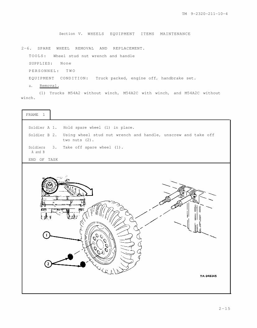
Section V. WHEELS EQUIPMENT ITEMS MAINTENANCE
2-6. SPARE WHEEL REMOVAL AND REPLACEMENT.
TOOLS: Wheel stud nut wrench and handle
SUPPLIES: None
PERSONNEL: T W O
EQUIPMENT CONDITION: Truck parked, engine off, handbrake set.
a. Removal.
(1) Trucks M54A2 without winch, M54A2C with winch, and M54A2C withoutwinch.
FRAME 1
Soldier A 1. Hold spare wheel (1) in place.
Soldier B 2. Using wheel stud nut wrench and handle, unscrew and take offtwo nuts (2).
Soldiers 3. Take off spare wheel (1).A and B
END OF TASK
2-15

TM 9-2320-211-10-4
(2) Trucks M54A2 with winch and M55A2 with winch.
FRAME 1
1. Using wheel stud nut wrench, unscrew and take off two nuts (1),two washers (2), and one spring (3) from two tire bolts (4).
2 . Lift out two tire bolts (4).
Soldiers 3. Slide out spare wheel (5) from carrier (6).A and B
END OF TASK
2-16

TM 9-2320-211-10-4
(3) Truck M51A2.
FRAME 1
Soldier A 1. Hold spare wheel clamp assembly (1) so it does not fall.
Soldier B 2. Using wheel stud nut wrench, unscrew and take off nut (2).Take out bolt (3) and lower spare wheel clamp assembly (1).
Soldiers 3. Take spare wheel (4) off truck.A and B
END OF TASK
2-17

TM 9-2320-211-10-4
b.
winch.
Replacement.
(1) Trucks M54A2 without winch, M54A2C with winch, and M54A2C without
FRAME 1
Soldiers 1. Lift spare wheel (1) into truck and slide spare wheel (1) ontoA and B two studs (2).
Soldier A 2. Hold spare wheel (1) in place,
Soldier B 3. Using wheel stud nut wrench, screw on and tighten two nuts (3).
END OF TASK
2-18

TM 9-2320-211-10-4
(2) Trucks M54A2 with winch and M55A2 with winch.
FRAME 1
SoldiersA and B
Soldier A
1.
2.
3.
4.
5.
END OF TASK
Lift spare wheel (1) and slide it
Place two tire bolts (3) throughcarrier (2) as shown.
Slide spring (4) and washer (5)Screw on nut (6).
into carrier (2).
holes in wheel (1) and
onto forward tire bolt (3).
Slide washer (7) onto rear tire bolt (3). Screw on nut (8).
Using wheel stud nut wrench, tighten nuts (6 and 8).
2-19

TM 9-2320-211-10-4
(3) Truck M51A2.
FRAME 1
Soldiers 1. Lift spare wheel (1) onto carrier (2).A and B
Soldier A 2. Put spare wheel clamp assembly (3) in place at end of carrier (2).
Soldier B 3. Hook bolt (4) into hole in bottom of carrier (2) and through holein spare wheel clamp assembly (3).
Soldier A 4. Using wheel stud nut wrench, screw on and tighten nut (5).
END OF TASK
2-20

TM 9-2320-211-10-4
2-7. JACKING PROCEDURE
N O T E
This task is the same for all wheels. Thistask is shown for the left rear-rear wheel.
TOOLS: Hydraulic screw jack with handle.
SUPPLIES: Wood block
PERSONNEL: One
EQUIPMENT CONDITION: Truck parked, engine off, handbrake set, wheelschocked.
W A R N I N G
Never get underneath truck that is held up byjack only. Jack may slip, causing truck to fallresulting in severe injury to personnel.
a. Raising Truck.
FRAME 1
1. Take hydraulic screw jack (1) and handle (2) out of stowage compartmentabove left running board.
2. Put wood block (3) on the ground under spring seat (4) and put screw jack(1) on wood block.
3. Turn out screw jack (1) until it touches spring seat (4).
4. Using slotted end of jack handle (2), turn bleeder valve (5) to the right. Putjack handle in screw jack (1).
5. Moving jack handle (2) up and down, raise wheel assembly (6) off ground.
END OF TASK
2-21

TM 9-2320-211-10-4
b. Lowering Truck.
FRAME 1
1. Take jack handle (1) out of hydraulic screw jack (2).
2. Using slotted end of jack handle (1), turn bleeder valve (3) to the left.
3. When wheel assembly (4) is firmly on the ground, take screw jack (2) out fromunder truck. Take wood block (5) away from truck.
4. Put screw jack (2) and handle (1) into stowage compartment above left runningboard.
END OF TASK
2 - 2 2

TM 9-2320-211-10-4
2-8. INNER GEARWHEELS REMOVAL AND REPLACEMENT.
N O T E
This task is the same for all four inner rear wheels.
TOOLS: Wheel stud nut wrenchHydraulic screw jack with handle
SUPPLIES: None
EQUIPMENT CONDITION: Truck parked on level ground, engine off, handbrakeset, wheels chocked.
a. Preliminary Procedures.
(1) Remove spare wheel if needed to replace damaged wheel. Refer topara 2-6.
(2) Jack up truck and remove outer rear wheel. Refer to para 2-7.
2-23

TM 9-2320-211-10-4
b. Removal.
FRAME 1
1. Using spare end of wheel stud nut wrench (1), unscrew and take off sixinner wheel nuts (2).
C A U T I O N
Do not slide wheel assembly on threaded studs. Slidingwheel assembly may damage threads.
N O T E
Nuts have left-hand threads on left wheel assembly andright-hand threads on right wheel assembly. Studs andnuts are stamped (L) left and (R) right.
2. Put fingers through vent holes (3) and grip wheelwheel, pull it toward you, and take it off.
END OF TASK
(4) as shown. Lift up on
2-24

TM 9-2320-211-10-4
c. Replacement.
FRAME 1
1. Check that truck is jacked up at wheel to be replaced.
C A U T I O N
Do not slide wheel assembly on threaded studs. Slidingwheel assembly may damage threads.
2. Lift wheel assembly (1) up and onto wheel studs (2).
N O T E
Nuts have left-hand threads on left wheel assembly andright-hand threads on right wheel assembly. Stud andnuts are stamped (L) left and (R) right.
3. Screw on and hand tighten nuts (3) on wheel studs (2).
4. Using square end of wheel stud nut wrench (4), tighten nuts (3) in ordershown. As soon as you can, take truck to organizational maintenance andhave wheel stud nuts torqued to 450 to 500 pound-feet.
5. Put on outer rear wheel and jack down truck. Refer to para 2-7.
2-25

TM 9-2320-211-10-4
FRAME 2
N O T E
Follow-on Maintenance Action Required:
1. If damaged wheel was replaced, take damaged wheelto organizational maintenance shop for repair or re-placement as soon as possible.
2. If damaged wheel cannot be taken immediately to or-ganizational maintenance, store damaged wheel onspare mounting bracket. Refer to para 2-6.
END OF TASK
2-26

TM 9-2320-211-10-4
2-9. FRONT AND OUTER REAR WHEELS REMOVAL AND REPLACEMENT.
N O T E
The following task is the same for both front wheels andall four outer rear wheels.
TOOLS: Wheel stud nut wrench and handleHydraulic screw jack and handle
SUPPLIES: None
PERSONNEL: One
EQUIPMENT CONDITION : Truck on level ground, engine off, handbrake set,wheels chocked.
a. Preliminary Procedures. Remove spare wheel if needed to replace damagedwheel. Refer to para 2-6.
b. Removal.
FRAME 1
1 . Using wheel stud nut wrench (1), loosen 10 wheel stud nuts (2). Do not takeoff wheel stud nuts.
N O T E
Wheel stud nuts (2) on left side have left hand threadsand must be turned to the right to loosen them. Wheelstud nuts on right side have right hand threads andmust be turned to the left to loosen them.
GO TO FRAME 2
2-27

TM 9-2320-211-10-4
FRAME 2
1. Turn out jack screw (1) about three inches.
2. Using slotted end of jack handle (2), turn bleeder valve (3) to right to close it.
3. Put hydraulic jack (4) under axle housing (5) near wheel assembly (6) to be taken off.Put jack handle (2) into hydraulic jack.
N O T E
Place a block between jack base and ground when truck is onloose or soft ground.
4. Move jack handle (2) up and down until wheel assembly (6) is off ground.
GO TO FRAME 3
2-28

TM 9-2320-211-10-4
FRAME 3
CAUTION
Do not slide wheel assembly on threaded studs. Slidingwheel assembly may damage threads.
1 . Using wheel stud nut wrench, unscrew and take off 10 wheel stud nuts (1).
2 . Put fingers through vent holes (2) and grip wheel (3) as shown. Lift up on wheel,pull it toward you, and take it off.
END OF TASK
2-29

TM 9-2320-211-10-4
c. Replacement.
FRAME 1
1 . Check that truck is jacked up at wheel to be replaced.
CAUTION
Do not slide wheel assembly on threaded studs. Slidingwheel assembly may damage threads.
2. Put wheel (1) over hub and drum assembly (2) onto wheel studs (3).
N O T E
Tire threads of rear wheels must be matched as closelyas possible and tire valves (4) must be across fromeach other as much as possible.
3. Screw on and finger tighten 10 wheel stud nuts (5).
GO TO FRAME 2
2-30

TM 9-2320-211-10-4
FRAME 2
1 . Using slotted end of jack handle (1) turn bleeder valve (2) to left to open it.
2 . Take hydraulic jack (3) from under axle housing (4) when tire (5) touches ground.
3. Turn jack screw (6) into hydraulic jack (3).
GO TO FRAME 3
2-31

TM 9-2320-211-10-4
FRAME 3
1. Using wheel stud nut wrench, tighten 10 wheel stud nuts (1) in the order shown. Assoon as you can, take truck to organizational maintenance and have wheel stud nutstorqued to 450-500 pound-feet.
1.
2.
END OF TASK
N O T E
Follow-on Maintenance Action Required:
If damaged wheel was replaced, take damaged wheel toorganizational maintenance shop for repair or replace-ment as soon as possible.If damaged wheel cannot be taken immediately to organi-zational maintenance, store damaged wheel on sparewheel mounting bracket. Refer to para 2-6.
2-32

TM 9-2320-211-10-4
Section VI. SPECIAL PURPOSE KITS EQUIPMENT ITEMS MAINTENANCE
2-10. INSTALLATION AND REMOVAL OF BOW AND TARP KITS.
TOOLS: Cross-tip screwdriver (Phillips type)
SUPPLIES: Chalk
PERSONNEL: TW O
EQUIPMENT CONDITION: Truck parked, engine off, handbrake set.
C A U T I O N
Do not fold or stow paulin or end curtains if they arewet. When folding, make sure surface they are spreadon is dry. Canvas canwet.
a. Installation of Bow Assemblies:
be damaged if it is stowed while
FRAME 1
1. Take corner and stake assemblies and bows (1) out of cargo bed.
GO TO FRAME 2
2-33

TM 9-2320-211-10-4
FRAME 2
1. Put bow (1) in place in two corner and stake assemblies (2) and align holes.
2. Using screwdriver, screw in and tighten two screws (3) on each corner andstake assembly (2).
3. Put bow assembly (4) in place in sockets (5).
4. Do steps 1 through 3 again for other five bow assemblies (4).
END OF TASK
2-34

TM 9-2320-211-10-4
b. Installation of End Curtains.
FRAME 1
1. Put two lashing ropes (1) through two eyelets (2) on rear end curtain (3)and pull them through until knots at ends of lashing ropes are against eyelets.
2 . Put rear end curtain (3) in place on bow (4).
3. Lace on lashing rope (1) around bow (4) and through all eyelets (2) on oneside of rear end curtain (3). Do the same thing with other lashing rope.
4. Loop lashing rope (1) around hook (5) and pull lashing rope tight and tie itonto hook (6). Do the same thing with other lashing rope.
N O T E
Do not tie or lash bottom of rear end curtain whencarrying passengers.
5. Join safety strap (7) to two eyelets (8) on top of side rail ends.
6. Do steps 1 through 4 again for front end curtain.
END OF TASK
2-35

TM 9-2320-211-10-4
c. Installation of Paulin.
FRAME 1
Soldiers 1. Put paulin (1) on middle of center bow (2) with the word FRONT onA and B top and open end facing to rear of truck as shown.
Soldier A 2. Hold paulin (1) so it does not fall or slide.
Soldier B 3. Unfold end of paulin (1) marked FRONT to front bow (3) and let ithang over bow as shown.
4. Hold paulin (1) in place on bows so that it does not move.
Soldier A 5. Unfold end of paulin marked REAR to rear bow (4) and let it hangover bow.
GO TO FRAME 2
2-36

TM 9-2320-211-10-4
FRAME 2
Soldier A 1. Hold paulin (1) so that it does not move on bows.
Soldier B 2. Unfold side (2) of paulin (1), then unfold side (3).
GO TO FRAME 3
2-37

TM 9-2320-211-10-4
FRAME 3
C A U T I O N
If lashing ropes are tied too tightly, paulin will tear.
1. Pull all lashing ropes (1) until they are snug and tie ropes to hooks (2) onfour sides of truck body (3).
END OF TASK
2-38
TM 9-2320-211-10-4
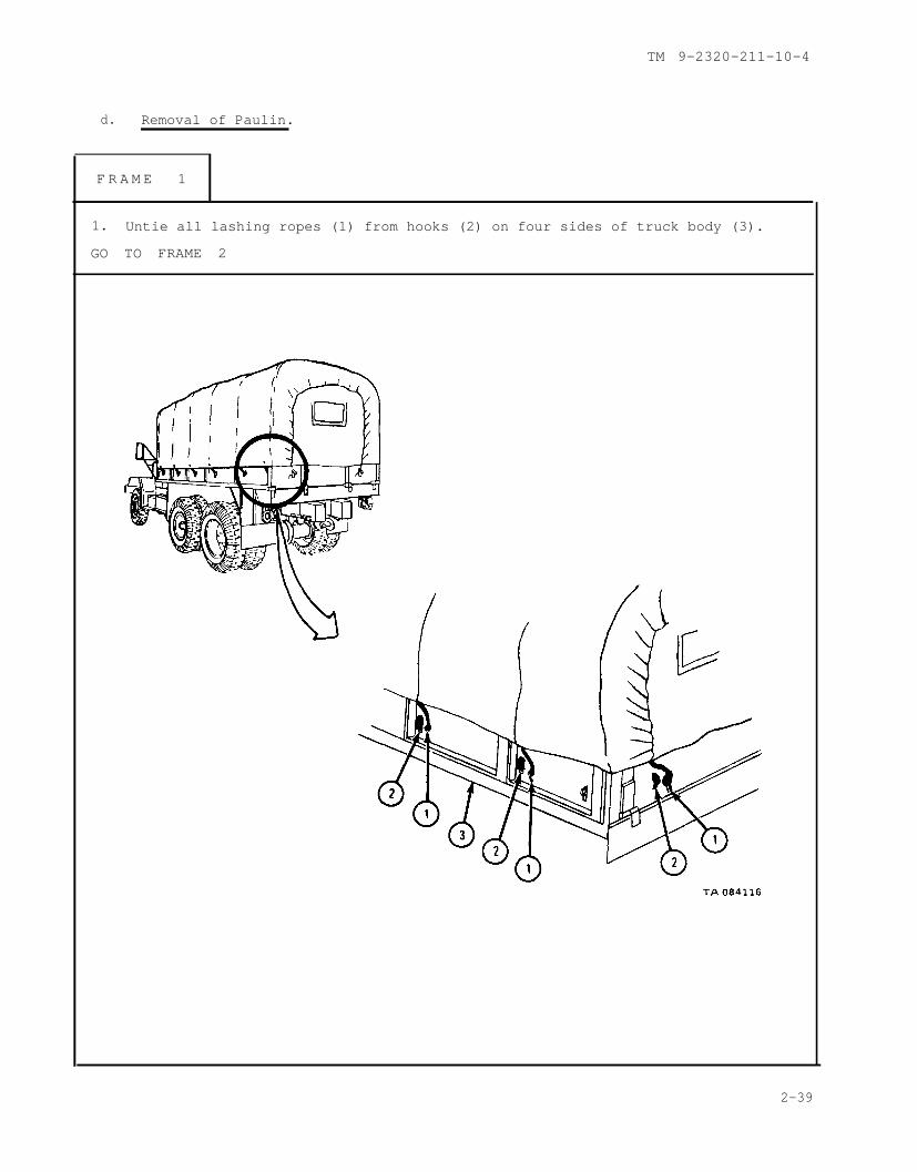
d. Removal of Paulin.
F R A M E 1
1. Untie all lashing ropes (1) from hooks (2) on four sides of truck body (3).
GO TO FRAME 2
2-39
TM 9-2320-211-10-4
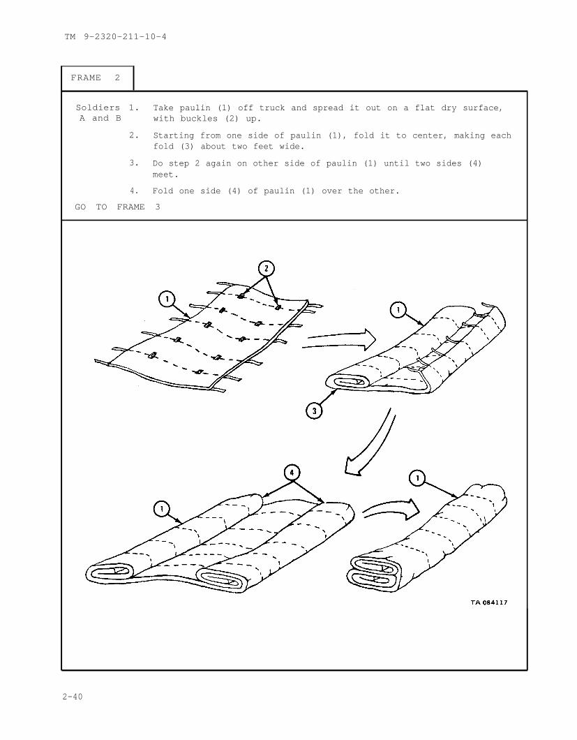
FRAME 2
Soldiers 1. Take paulin (1) off truck and spread it out on a flat dry surface,A and B with buckles (2) up.
2. Starting from one side of paulin (1), fold it to center, making eachfold (3) about two feet wide.
3. Do step 2 again on other side of paulin (1) until two sides (4)meet.
4. Fold one side (4) of paulin (1) over the other.
GO TO FRAME 3
2-40

TM 9-2320-211-10-4
FRAME 3
Soldiers 1. Starting from front or back of paulin (1), fold end to center, A and B making each fold (2) about two feet wide.
2. Do step 1 again on the other side of paulin (1) until two ends (3)meet. Fold one end over the other.
3. Put front end of paulin (1) up. Using chalk, mark FRONT onpaulin. Turn paulin over and mark REAR on the other side.
4. Stow paulin (1).
END OF TASK
2-41

TM 9-2320-211-10-4
e. Removal of End Curtains.
FRAME 1
1. Untie two lashing ropes (1) from two hooks (2).
2. Unwind lashing ropes (1) from rear end curtain eyelets (3) and end bow (4)and take out two lashing ropes.
3. Take safety strap (5) out of two eyelets (6). Put end curtain (7) on a flat drysurface and put coiled ropes (1) on rear end curtain. Fold end curtain toabout same size as folded paulin.
4. Do steps 1 through 3 again for front end curtain.
5. Stow end curtains with paulin.
END OF TASK
2-42

TM 9-2320-211-10-4
f. Removal of Bow Assemblies.
FRAME 1
1 . Lift bow assembly (1) out of two sockets
2 . Using phillip screwdriver, unscrew andcorners and stake assemblies (4).
3 . Pull bow (5) out of two corner and stake
(2).
take out two screws (3) from two
assemblies (4).
4. Do steps 1 through 3 again for other five bow assemblies (1).
GO TO FRAME 2
2-43

TM 9-2320-211-10-4
FRAME 2
1 . Stow corner and stake assemblies (1) and bows on cargo bed.
END OF TASK
2 - 4 4

By Order of the Secretaries of the Army and Air Force:
Off icial :
E . C. MEYER
J . C . P E N N I N G T O NMajor General, United States Army
The Adjutant General
Official:
General, United States ArmyChief of Staff
LEW ALLEN, JR., General, USAFChief of Staff
V A N L . C R A W F O R D , J R . , C o l o n e l , U S A F
Director of Administration
DISTRIBUTION:
To be distributed in accordance with DA Form 12-38, Operator maintenancerequirements for 5-Ton Truck Chassis: 5-Ton, 6x6, M39A2.
U.S. GOVERNMENT PRINTING OFFICE: 1980-603128/279