tm 5-3805-264-14&p - liberated manuals.comtm 5-3805-264-14&p a for information on first aid,...
TRANSCRIPT

TM 5-3805-264-14&P
OPERATOR’S, UNIT, DIRECT SUPPORT, AND GENERAL SUPPORT MAINTENANCE MANUAL
WITH
REPAIR PARTS AND SPECIAL TOOLS LISTSFOR
TRUCK, DUMP, HEAVY, BODYM917A1 (NSN 3805-01-431-1165) (EIC:E5C)M917A2 (NSN 3805-01-488-7442) (EIC:BPB)
AND
M917A1 W/MCS (MATERIAL CONTROL SYSTEM)(NSN 3805-01-432-8249) (EIC: E5D)
M917A2 W/MCS (MATERIAL CONTROL SYSTEM)(NSN 3805-01-488-6963) (EIC: BA4)
This manual supersedes TM 5-3805-264-14&P dated December 1997
Approved for public release; distribution is unlimited.
HEADQUARTERS, DEPARTMENT OF THE ARMYDECEMBER 2005


TM 5-3805-264-14&P
CHANGE HEADQUARTERSNo. 1 DEPARTMENT OF THE ARMY
WASHINGTON, D.C., 14 February 2011
TECHNICAL MANUALOPERATOR’S, UNIT, DIRECT SUPPORT, AND GENERAL SUPPORT
MAINTENANCE MANUAL
WITH
REPAIR PARTS AND SPECIAL TOOLS LISTS
FOR
TRUCK, DUMP, HEAVY, BODYM917A1 (NSN 3805-01-431-1165) (EIC:E5C)M917A2 (NSN 3805-01-488-7442) (EIC:BPB)
AND
M917A1 W/MCS (MATERIAL CONTROL SYSTEM)(NSN 3805-01-432-8249) (EIC:E5D)
M917A2 W/MCS (MATERIAL CONTROL SYSTEM) (NSN 3805-01-488-6963) (EIC:BA4)
DISTRIBUTION STATEMENT A - Approved for public release; distribution is unlimited.
TM 5-3805-264-14&P, dated 30 December 2005, is changed as follows:1. File this sheet in front of the publication for reference purposes.2. New or updated material is indicated by an asterisk in the outer margin of the page.3. Remove old pages and insert new pages as indicated below:
Remove Pages Insert Pages
A/(B Blank) A/(B Blank)i and 1-0 i and 1-0
11-1 and Figure 12 11-1 and Figure 12I-3 thru I-6 I-3 thru I-6
I-13 and I-14 I-13 and I-14DA Form 2028 Sample DA Form 2028 Sample
DA From 2028 (Three copies) DA From 2028 (Three copies)

TM 5-3805-264-14&P
By Order of the Secretary of the Army:
GEORGE W. CASEY, JR.General, United States Army
Chief of StaffOfficial:
DISTRIBUTION:
To be distributed in accordance with the initial distribution requirements for IDN 381066 TM 5-3805-264-14&P.
1101301

TM 5-3805-264-14&P
a
FOR INFORMATION ON FIRST AID, REFER TO FM 4-25.11.
WARNING
CARBON MONOXIDE (EXHAUST GASES) CAN KILL!Carbon monoxide is a colorless, odorless, deadly poison which, when breathed, deprives the body of oxygen andcauses suffocation. Exposure to air containing carbon monoxide produces symptoms of headache, dizziness, lossof muscular control, apparent drowsiness, and coma. Permanent brain damage or death can result from severeexposure.Carbon monoxide occurs in exhaust fumes of internal combustion engines. Carbon monoxide can become danger-ously concentrated under conditions of inadequate ventilation. The following precautions must be observed toensure safety of personnel when engine of dump truck is operated.
1. DO NOT operate engine in enclosed areas.
2. DO NOT idle engine for long periods without maintaining adequate ventilation in cab.
3. DO NOT drive dump truck with inspection plates or cover plates removed.
4. BE ALERT at all times for exhaust poisoning symptoms. They are:
• Headache
• Dizziness
• Sleepiness
• Loss of muscular control
5. If you see another person with exhaust poisoning symptoms:
• Remove person from area.
• Expose to fresh air.
• Keep person warm.
• Do not permit physical exercise.
• Administer cardiopulmonary resuscitation (CPR), if necessary.
• Notify a medic.
6. BE AWARE. The field protective mask for nuclear-biological-chemical (NBC) protection will not protect youfrom carbon monoxide poisoning.
THE BEST DEFENSE AGAINST CARBON MONOXIDE POISONING IS GOOD VENTILATION!

TM 5-3805-264-14&P
b
WARNING
CARGO COVER OPERATIONObserve the following safety regulations when operating cargo cover:
• Never operate cargo cover under obstructions, such as trees and power lines.• Ensure that all personnel are clear of rear of dump body and the immediate area of the cover.
• Ensure that chain cover is in place.• Keep all clothing away from moving parts.• DO NOT cover load with crank handle installed.
• DO NOT use cargo cover frame as a grabhandle.Failure to follow this warning may result in death or injury to personnel.
WARNING
CLEANING AGENTS• Dry cleaning solvent MIL-PRF-680 Type III is an environmentally compliant and low toxic material. However, it
may be irritating to the eyes and skin. The use of protective gloves and goggles is suggested. Use in well-ven-tilated area. Keep away from open flame and other sources of ignition.
• Improper cleaning methods and use of unauthorized cleaning liquids or solvents can injure personnel anddamage equipment. To prevent this, refer to TM 9-247 for further instructions.
WARNING
COMPRESSED AIRCompressed air used for cleaning or drying purposes, or for clearing restrictions, should never exceed 30 psi (207kPa). Wear protective clothing (goggles/shield, gloves, etc.) and use caution to avoid injury to personnel.
WARNING
DUMP BODY OPERATION• Hearing protection is required when performing loading or dumping operations. Failure to follow this warning
may result in injury to personnel.
• Ensure that parking brake is set before loading dump truck (TM 9-2320-363-10 or TM 9-2320-302-10). If park-ing brake is not set, dump truck could roll or shift position. Failure to follow this warning may result in death orinjury to personnel or damage to equipment.
• Stand clear of dump body during loading operation. Material being loaded could fall on personnel standing tooclose. Failure to follow this warning may result in death or injury to personnel.
• NEVER unlock tailgate or operate MCS tailgate or gates, or operate hydraulic control lever in cab without firstensuring that all personnel are clear of dump body. Failure to follow this warning may result in injury to person-nel.
• NEVER raise dump body without first checking for overhead obstructions such as trees and power lines.Ensure that overhead clearance is sufficient. Failure to follow this warning may cause death or injury to person-nel.

TM 5-3805-264-14&P
c
WARNING
DUMP BODY OPERATION (Con’t)
• NEVER raise dump body more than half way with tailgate or MCS gates closed. If dump body is raised fullywithout opening tailgate/MCS gates, dump truck center of gravity will shift rearward. Dump truck could tip,causing injury to personnel or damage to equipment.
• DO NOT spread or dump payload with dump truck facing a steep upgrade or a steep side slope. Dump truckmay tip over backward or sideways. Failure to follow this warning may result in death or injury to personnel ordamage to equipment.
• DO NOT park on a slope. Park on level ground only. Parking on a slope could cause load to shift and dumptruck to tip over. Failure to follow this warning may result in death or injury to personnel or damage to equip-ment.
• DO NOT attempt to dump in high wind. High winds may disperse aggregate. High winds may also cause dumptruck to roll over when dump body is raised. Failure to follow this warning may result in death or injury to per-sonnel or damage to equipment.
• Stay at controls while dumping. If dump body leans or shifts to one side, lower it immediately and check for oneof the following:
• underinflated or flat tires
• tires sinking in soft soil
• load shifting to one side of body
• high or gusty wind
• weak or broken leaf spring
If one of these or any other problems are found, do not continue dumping until the problem is corrected. Failureto follow this warning may result in death or injury to personnel or damage to equipment.
• DO NOT try to loosen a sticky load by pulling forward or backward and braking abruptly. Injury to personnel ordamage to equipment may result.
WARNING
HAZARDOUS WASTE DISPOSAL
When servicing this vehicle, performing maintenance, or disposing of materials such as engine coolant, transmis-sion fluid, lubricants, battery acids or batteries, and CARC paint, consult your Unit/Local Hazardous Waste Dis-posal Center or safety office for local regulatory guidance. If further information is needed, please contact the ArmyEnvironmental Hotline at 1-800-872-3845.
WARNING
HEAVY COMPONENTS
• Use extreme care when handling heavy parts. Lifting cables, chains, hooks, and slings must be in good condi-tion and of suitable capacity. Keep clear of parts supported only by lifting device. Failure to follow this warningmay result in death or injury to personnel and damage to equipment.
• Dump body side boards weigh approximately 65 lb (30 kg) each. Two personnel are required to install orremove side boards. Failure to follow this warning may cause injury to personnel.
TM 5-3805-264-14&P
d
WARNING
HYDRAULIC SYSTEM
• DO NOT disconnect hydraulic lines while engine is running. Engine must be shut down and dump body fullylowered or supported on body props before lines are disconnected. Escaping hydraulic fluid under pressurecan penetrate the skin, causing serious injury to personnel.
• To prevent burns, use caution when removing fill cap of hydraulic reservoir when hydraulic fluid is hot. Avoidcontact with hot hydraulic oil. Use extreme care when filling, sampling or draining hydraulic oil. Failure to followthis warning may result in injury to personnel.
WARNING
MATERIAL CONTROL SYSTEM (MCS)
• Use extreme caution when adjusting MCS gate openings. NEVER adjust gate openings when gates are open.Failure to follow this warning could result in injury to personnel.
• Keep hands and feet away from gate openings at all times. Failure to follow this warning could result in injury topersonnel.
• DO NOT stand or walk behind dump truck when it is dumping or in raised position. When using MCS remotecontrol, always walk or stand to side of dump body. Failure to follow this warning may result in personnel injury.
• DO NOT connect or disconnect MCS remote control when dump body is being raised or lowered. Failure to fol-low this warning may cause personnel injury.
• When connected, MCS remote control overrides cab control unit. When remote control is disconnected, cabcontrol activates. To avoid inadvertent opening or closing of gates, ALWAYS check gate positions and positionof toggle switches on both cab and remote controls before plugging in or unplugging remote control. Toggleswitches should be in CLOSED position. Failure to follow this warning may cause personnel injury.
• Care must be exercised when using the Material Control System (MCS). In the event material fails to flowthrough gates, open gate using open control and clear jam using BII shovel. DO NOT attempt to clear materialusing your hands or feet. Failure to follow this warning may cause injury to personnel.
WARNING
WORK SAFETY
• Unless otherwise specified, perform all maintenance with dump truck on level ground, transmission in N (Neu-tral), parking brake set, and engine off. Failure to follow this warning may result in personnel injury.
• Wear eye protection when using high pressure stream of water to clean dump body. Failure to follow this warn-ing may result in injury to personnel.
• NEVER work under a raised dump body unless it is secured in the raised position with body props and dumpbody is EMPTY. Failure to follow this warning may result in death or injury to personnel.
• Although battery ground cable must be connected in order to test electrical circuit voltage, disconnect batteryground cable before performing resistance tests or replacing parts. This will prevent shock to personnel, anddamage to parts and equipment.
• DO NOT touch heat shrinkable tubing for at least 30 seconds after heating. Heat shrinkable tubing is hot andwill burn you.
TM 5-3805-264-14&P
e/(f Blank)
• Hydraulic cylinder sleeves may extend downward as hydraulic cylinder is lifted. Expect sleeve movement anytime hydraulic cylinder is handled. Failure to do so may result in serious injury to personnel.
• DO NOT disconnect tailgate release or MCS air lines while chassis or MCS air systems are pressurized. Airsystem pressure must be released before air lines are disconnected. A line disconnected under pressure maycause personnel injury.
• Provide adequate ventilation and personal protective equipment before starting any welding operation (TM 9-237). Contact your unit/local Industrial Hygienist or Safety Officer for assistance. Failure to follow this warningmay result in injury to personnel.
WARNING
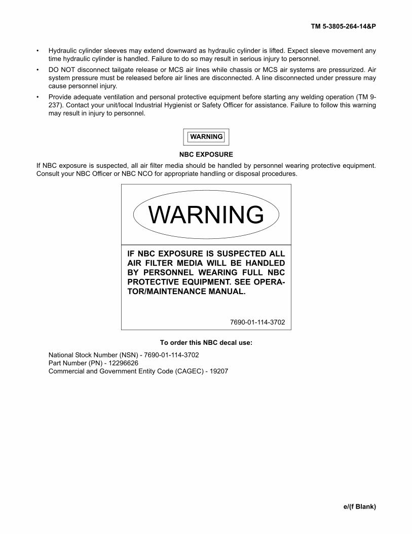
NBC EXPOSUREIf NBC exposure is suspected, all air filter media should be handled by personnel wearing protective equipment.Consult your NBC Officer or NBC NCO for appropriate handling or disposal procedures.
To order this NBC decal use:
National Stock Number (NSN) - 7690-01-114-3702Part Number (PN) - 12296626Commercial and Government Entity Code (CAGEC) - 19207
WARNINGIF NBC EXPOSURE IS SUSPECTED ALLAIR FILTER MEDIA WILL BE HANDLEDBY PERSONNEL WEARING FULL NBCPROTECTIVE EQUIPMENT. SEE OPERA-TOR/MAINTENANCE MANUAL.
7690-01-114-3702


TM 5-3805-264-14&P
A/(B Blank)
LIST OF EFFECTIVE PAGES/WORK PACKAGES
Dates of issue for original and change pages are:
Original 30 December 2005Change 1 14 February 2011
TOTAL NUMBER OF PAGES IN THIS PUBLICATION IS 412 CONSISTING OF THE FOLLOWING:
Page *ChangeNo. No.
Page *ChangeNo. No.
Cover (Back Blank) 0a thru e/(f Blank) 0i thru v 11-0 01-1 thru 1-3/(1-4 Blank) 01-5 thru 1-13/(1-14 Blank) 01-15 thru 1-19/(1-20 Blank) 02-1 thru 2-5/(2-6 Blank) 02-7 thru 2-25/(2-26 Blank) 02-27 thru 2-42 02-43/(2-44 Blank) 03-1/(3-2 Blank) 03-3 thru 3-7/(3-8 Blank) 03-9/(3-10 Blank) 04-1 thru 4-152 05-1 thru 5-35/(5-36 Blank) 06-1/(6-2 Blank) 0A-1 thru A-2 0B-1 thru B-8 0C-1 thru C-7 0Figure 1 thru Figure 11 011-1 1
Figure 12 thru Figure 24 0BULK-1 0KITS-1 0I-1 and I-2 0I-3 1I-4 0I-5 1I-6 thru I-12 0I-13 1I-14 0D-1 thru D-3/(D-4 Blank) 0E-1/(E-2 Blank) 0F-1 thru F-4 0G-1 thru G-3/(G-4 Blank) 0H-1 thru H-2 0I-1 thru I-2 0J-1 thru J-8 0Index-1 thru Index 7/(Index 8 Blank) 0Sample DA Form 2028 1Blank DA Form 2028-2 (Three copies) 1Metric Conversion Chart 0Back Cover 0
* Zero in this column indicates an original page or work package.


TM 5-3805-264-14&P
i Change 1
TECHNICAL MANUAL HEADQUARTERS*TM 5-3805-264-14&P DEPARTMENT OF THE ARMY
WASHINGTON, D.C., 30 December 2005
OPERATOR’S, UNIT, DIRECT SUPPORT, AND GENERAL SUPPORT MAINTENANCE MANUAL
WITHREPAIR PARTS AND SPECIAL TOOLS LISTS
FOR
TRUCK, DUMP, HEAVY, BODYM917A1 (NSN 3805-01-431-1165) (EIC: E5C)M917A2 (NSN 3805-01-488-7442 (EIC: BPB)
AND
M917A1 W/MCS (MATERIAL CONTROL SYSTEM)(NSN 3805-01-432-8249) (EIC: E5D)
M917A2 W/MCS (MATERIAL CONTROL SYSTEM)(NSN 3805-01-488-6963) (EIC: BA4)
Current as of 5 July 2005
*SUPERSEDURE NOTICE - This manual supersedes TM 5-3805-264-14&P dated December 1997
DISTRIBUTION STATEMENT A - Approved for public release; distribution is unlimited.
TABLE OF CONTENTS
Page
Warning Summary . . . . . . . . . . . . . . . . . . . . . . . . . . . . . . . . . . . . . . . . . . . . . aHow To Use This Manual. . . . . . . . . . . . . . . . . . . . . . . . . . . . . . . . . . . . . . . . v
CHAPTER 1 INTRODUCTION . . . . . . . . . . . . . . . . . . . . . . . . . . . . . . . . . . . . . . . . . . . . . . . . . . . 1-1
Section I. General Information . . . . . . . . . . . . . . . . . . . . . . . . . . . . . . . . . . . . . . . . . . . . 1-1Section II. Equipment Description and Data . . . . . . . . . . . . . . . . . . . . . . . . . . . . . . . . . . 1-5Section III. Principles of Operation. . . . . . . . . . . . . . . . . . . . . . . . . . . . . . . . . . . . . . . . . . 1-15
REPORTING ERRORS AND RECOMMENDING IMPROVEMENTS
You can help improve this publication. If you find any errors, or if you would like to recommend any improvements to theprocedures in this publication, please let us know. The preferred method is to submit your DA Form 2028 (RecommendedChanges to Publications and Blank Forms) through the Internet, on the Army Electronic Product Support (AEPS) website.The Internet address is https://aeps.ria.army.mil. The DA Form 2028 is located under the Public Applications section in theAEPS Public Home Page. Fill out the form and click on SUBMIT. Using this form on the AEPS will enable us to respondquicker to your comments and better manage the DA Form 2028 program. You may also mail, E-mail, or fax your com-ments or DA Form 2028 directly to the U.S. Army TACOM Life Cycle Management Command. The postal mail address isU.S. Army TACOM Life Cycle Management Command, ATTN: AMSTA-LCL-MPP/TECH PUBS, 6501 E 11 Mile Road,Warren, MI 48397-5000. The E-mail address is [email protected]. The fax number is DSN 793-0726or Commercial (309) 782-0726.

TM 5-3805-264-14&P
Change 1 ii
TABLE OF CONTENTS (Con’t)
Illus/Fig Page
CHAPTER 2 OPERATING INSTRUCTIONS. . . . . . . . . . . . . . . . . . . . . . . . . . . . . . . . . . . . . . . . 2-1Section I. Description and Use of Operator’s Controls and Indicators . . . . . . . . . . . . . 2-1Section II. Operator Preventive Maintenance Checks and Services (PMCS) . . . . . . . . 2-7Section III. Operation Under Usual Conditions. . . . . . . . . . . . . . . . . . . . . . . . . . . . . . . . 2-27Section IV. Operation Under Unusual Conditions. . . . . . . . . . . . . . . . . . . . . . . . . . . . . . 2-43
CHAPTER 3 OPERATOR MAINTENANCE . . . . . . . . . . . . . . . . . . . . . . . . . . . . . . . . . . . . . . . . 3-1Section I. Lubrication Instructions . . . . . . . . . . . . . . . . . . . . . . . . . . . . . . . . . . . . . . . . 3-1Section II. Operator Troubleshooting Procedures . . . . . . . . . . . . . . . . . . . . . . . . . . . . . 3-3Section III. Operator Maintenance . . . . . . . . . . . . . . . . . . . . . . . . . . . . . . . . . . . . . . . . . 3-9
CHAPTER 4 UNIT MAINTENANCE . . . . . . . . . . . . . . . . . . . . . . . . . . . . . . . . . . . . . . . . . . . . . . 4-1Section I. Repair Parts; Special Tools; Test, Measurement, and Diagnostic
Equipment (TMDE); and Support Equipment. . . . . . . . . . . . . . . . . . . . . . . . 4-1Section II. Service Upon Receipt. . . . . . . . . . . . . . . . . . . . . . . . . . . . . . . . . . . . . . . . . . 4-2Section III. General Maintenance Instructions . . . . . . . . . . . . . . . . . . . . . . . . . . . . . . . . 4-3Section IV. Unit Preventive Maintenance Checks and Services (PMCS). . . . . . . . . . . . 4-13Section V. Unit Troubleshooting Procedures. . . . . . . . . . . . . . . . . . . . . . . . . . . . . . . . . 4-26Section VI. Electrical System Maintenance . . . . . . . . . . . . . . . . . . . . . . . . . . . . . . . . . . 4-32Section VII. Dump Body Maintenance . . . . . . . . . . . . . . . . . . . . . . . . . . . . . . . . . . . . . . . 4-66Section VIII. Dump Body Accessory Items Maintenance . . . . . . . . . . . . . . . . . . . . . . . . . 4-101Section IX. Hydraulic System Maintenance . . . . . . . . . . . . . . . . . . . . . . . . . . . . . . . . . . 4-117Section X. Preparation for Storage or Shipment . . . . . . . . . . . . . . . . . . . . . . . . . . . . . . 4-149
CHAPTER 5 DIRECT SUPPORT MAINTENANCE. . . . . . . . . . . . . . . . . . . . . . . . . . . . . . . . . . . 5-1Section I. Dump Body Maintenance . . . . . . . . . . . . . . . . . . . . . . . . . . . . . . . . . . . . . . . 5-1Section II. Dump Body Accessory Items Maintenance . . . . . . . . . . . . . . . . . . . . . . . . . 5-9Section III. Hydraulic System Maintenance . . . . . . . . . . . . . . . . . . . . . . . . . . . . . . . . . . 5-10
CHAPTER 6 GENERAL SUPPORT MAINTENANCE . . . . . . . . . . . . . . . . . . . . . . . . . . . . . . . . . 6-1APPENDIX A REFERENCES . . . . . . . . . . . . . . . . . . . . . . . . . . . . . . . . . . . . . . . . . . . . . . . . . . . . A-1APPENDIX B MAINTENANCE ALLOCATION CHART . . . . . . . . . . . . . . . . . . . . . . . . . . . . . . . . B-1APPENDIX C REPAIR PARTS AND SPECIAL TOOLS LISTS (RPSTL) . . . . . . . . . . . . . . . . . . . C-1
Section I. Introduction. . . . . . . . . . . . . . . . . . . . . . . . . . . . . . . . . . . . . . . . . . . . . . . . . . C-1Section II. Repair Parts List . . . . . . . . . . . . . . . . . . . . . . . . . . . . . . . . . . . . . . . . . . . . . . 1-1
GROUP 06 ELECTRICAL SYSTEM
0608 - MISCELLANEOUS ITEMS ......................................................................................... 1-1CONTROL UNIT ASSEMBLY, MCS .......................................................................... 1 1-1CONTROL SWITCHES, MCS .................................................................................... 2 2-1
0609 - LIGHTS....................................................................................................................... 3-1TAILLIGHTS, MARKER LIGHTS AND REFLECTORS .............................................. 3 3-1WIRING HARNESS, BEACON LIGHT ....................................................................... 4 4-1
0610 - SENDING UNITS AND WARNING SWITCHES......................................................... 5-1BODYUP AND TRANSPORT LOCK SWITCHES ...................................................... 5 5-1
0613 - HULL OR CHASSIS WIRING HARNESS................................................................... 6-1WIRING HARNESS, DUMP BODY LIGHTS .............................................................. 6 6-1MCS GATE HARNESS AND MCS POWER HARNESS ............................................ 7 7-1BODYUP/TRANSPORT LOCK HARNESS AND MATERIAL CONTROLCHASSIS HARNESS.................................................................................................. 8 8-1

TM 5-3805-264-14&P
iii Change 1
TABLE OF CONTENTS (Con’t)
Illus/Fig Page
GROUP 18 BODY, CAB, HOOD, AND HULL
1810 - CARGO BODY ........................................................................................................... 9-1CYLINDER SUPPORT FRAME AND BRACKETS .................................................... 9 9-1STABILIZER AND REAR HINGE............................................................................... 10 10-1DUMP BODY ASSEMBLY ......................................................................................... 11 11-1MCS TAILGATE ASSEMBLY..................................................................................... 12 12-1AIR CYLINDER ASSEMBLY...................................................................................... 13 13-1AIR TANK, LINES AND FITTINGS............................................................................. 14 14-1
GROUP 22 BODY, CHASSIS, AND HULL ACCESSORY ITEMS
2201 - CANVAS, RUBBER OR PLASTIC ITEMS ................................................................. 15-1CARGO COVER AND COMPONENT PARTS........................................................... 15 15-1SHOVEL MOUNTING ................................................................................................ 16 16-1
2210 - DATA PLATES AND INSTRUCTIONS HOLDERS .................................................... 17-1DECALS ..................................................................................................................... 17 17-1
GROUP 24 HYDRAULIC AND FLUID SYSTEMS
2401 - PUMP AND MOTOR .................................................................................................. 18-1HYDRAULIC PUMP ASSEMBLY............................................................................... 18 18-1
2403 - HYDRAULIC CONTROLS AND/OR MANUAL CONTROLS...................................... 19-1DUMP CONTROL AND CABLE ................................................................................. 19 19-1
2406 - STRAINERS, FILTERS, LINES AND FITTINGS, ETC............................................... 20-1FILTER ELEMENT, HYDRAULIC .............................................................................. 20 20-1HYDRAULIC HOSES AND FITTINGS ....................................................................... 21 21-1
2407 - HYDRAULIC CYLINDERS ......................................................................................... 22-1CYLINDER ASSEMBLY, HOIST ................................................................................ 22 22-1
2408 - LIQUID TANKS OR RESERVOIRS............................................................................ 23-1HYDRAULIC RESERVOIR ASSEMBLY .................................................................... 23 23-1
GROUP 33 SPECIAL PURPOSE KITS
3307 - SPECIAL PURPOSE KITS......................................................................................... 24-1SPILL SHIELD............................................................................................................ 24 24-1
GROUP 94 REPAIR KITS
9401 - REPAIR KITS ............................................................................................................. KITS KITS-1
GROUP 95 GENERAL USE STANDARDIZED PARTS
9501 - HARDWARE SUPPLIES AND BULK MATERIEL, COMMON BULK-1BULK .......................................................................................................................... BULK BULK-1
Section IV. Cross-Reference Indexes
NATIONAL STOCK NUMBER INDEX........................................................................ I-1PART NUMBER INDEX ............................................................................................. I-5
APPENDIX D COMPONENTS OF END ITEM AND BASIC ISSUE ITEMS LISTS . . . . . . . . . . . . D-1
APPENDIX E ADDITIONAL AUTHORIZATION LIST . . . . . . . . . . . . . . . . . . . . . . . . . . . . . . . . . . . E-1
APPENDIX F EXPENDABLE AND DURABLE ITEMS LIST . . . . . . . . . . . . . . . . . . . . . . . . . . . . . F-1
APPENDIX G ILLUSTRATED LIST OF MANUFACTURED ITEMS . . . . . . . . . . . . . . . . . . . . . . . . G-1

TM 5-3805-264-14&P
Change 1 iv
TABLE OF CONTENTS (Con’t)
Page
APPENDIX H TORQUE LIMITS . . . . . . . . . . . . . . . . . . . . . . . . . . . . . . . . . . . . . . . . . . . . . . . . . . H-1
APPENDIX I TOOL IDENTIFICATION LIST . . . . . . . . . . . . . . . . . . . . . . . . . . . . . . . . . . . . . . . . I-1
APPENDIX J LUBRICATION INSTRUCTIONS . . . . . . . . . . . . . . . . . . . . . . . . . . . . . . . . . . . . . . J-1
INDEX. . . . . . . . . . . . . . . . . . . . . . . . . . . . . . . . . . . . . . . . . . . . . . . . . . . . . . . . . . . Index 1
TM 5-3805-264-14&P
v Change 1
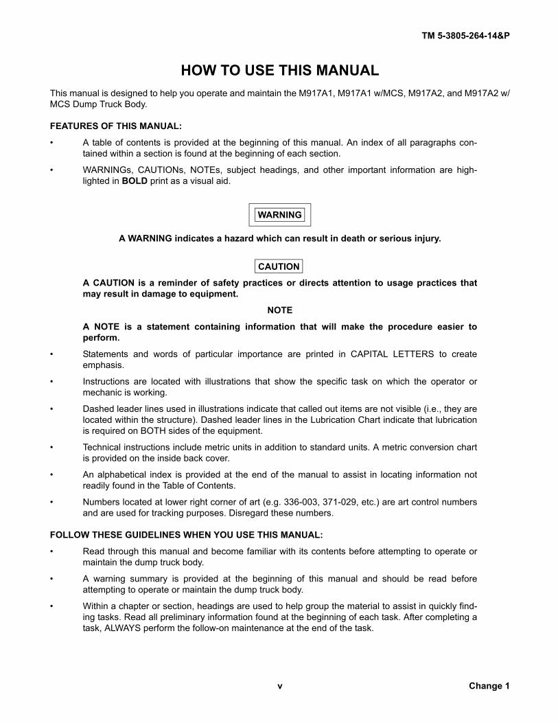
HOW TO USE THIS MANUALThis manual is designed to help you operate and maintain the M917A1, M917A1 w/MCS, M917A2, and M917A2 w/MCS Dump Truck Body.
FEATURES OF THIS MANUAL:
• A table of contents is provided at the beginning of this manual. An index of all paragraphs con-tained within a section is found at the beginning of each section.
• WARNINGs, CAUTIONs, NOTEs, subject headings, and other important information are high-lighted in BOLD print as a visual aid.
WARNING
A WARNING indicates a hazard which can result in death or serious injury.
CAUTION
A CAUTION is a reminder of safety practices or directs attention to usage practices thatmay result in damage to equipment.
NOTE
A NOTE is a statement containing information that will make the procedure easier toperform.
• Statements and words of particular importance are printed in CAPITAL LETTERS to createemphasis.
• Instructions are located with illustrations that show the specific task on which the operator ormechanic is working.
• Dashed leader lines used in illustrations indicate that called out items are not visible (i.e., they arelocated within the structure). Dashed leader lines in the Lubrication Chart indicate that lubricationis required on BOTH sides of the equipment.
• Technical instructions include metric units in addition to standard units. A metric conversion chartis provided on the inside back cover.
• An alphabetical index is provided at the end of the manual to assist in locating information notreadily found in the Table of Contents.
• Numbers located at lower right corner of art (e.g. 336-003, 371-029, etc.) are art control numbersand are used for tracking purposes. Disregard these numbers.
FOLLOW THESE GUIDELINES WHEN YOU USE THIS MANUAL:
• Read through this manual and become familiar with its contents before attempting to operate ormaintain the dump truck body.
• A warning summary is provided at the beginning of this manual and should be read beforeattempting to operate or maintain the dump truck body.
• Within a chapter or section, headings are used to help group the material to assist in quickly find-ing tasks. Read all preliminary information found at the beginning of each task. After completing atask, ALWAYS perform the follow-on maintenance at the end of the task.

TM 5-3805-264-14&P
1-0
BeaconWarningLight
CabShield
Cargo CoverControls
SideBoard
Tailgate
DumpBody
M917A1/M917A2
CargoCover
Stabilizer
HydraulicReservoir
HydraulicCylinder
Tool/Storage Box
MaterialControlSystem(MCS) Tailgate
BodyProp
M917A1 W/MCS / M917A2 W/MCS

TM 5-3805-264-14&P
1-1
CHAPTER 1INTRODUCTION
Section I. GENERAL INFORMATION
Paragraph Page Number Paragraph Title Number
1-1. Scope . . . . . . . . . . . . . . . . . . . . . . . . . . . . . . . . . . . . . . . . . . . . . . . . . . . . . . . . . . . . . . . . . . 1-11-2. Maintenance Forms, Records, and Reports . . . . . . . . . . . . . . . . . . . . . . . . . . . . . . . . . . . . . 1-11-3. Destruction of Army Materiel to Prevent Enemy Use . . . . . . . . . . . . . . . . . . . . . . . . . . . . . . 1-11-4. Preparation for Storage or Shipment . . . . . . . . . . . . . . . . . . . . . . . . . . . . . . . . . . . . . . . . . . 1-21-5. Official Nomenclature, Names, Designations, and Abbreviations . . . . . . . . . . . . . . . . . . . . 1-21-6. Reporting Equipment Improvement Recommendations (EIRs) . . . . . . . . . . . . . . . . . . . . . . 1-21-7. Warranty Information . . . . . . . . . . . . . . . . . . . . . . . . . . . . . . . . . . . . . . . . . . . . . . . . . . . . . . 1-21-8. Safety, Care, and Handling. . . . . . . . . . . . . . . . . . . . . . . . . . . . . . . . . . . . . . . . . . . . . . . . . . 1-21-9. Corrosion Prevention and Control (CPC) . . . . . . . . . . . . . . . . . . . . . . . . . . . . . . . . . . . . . . . 1-3
1-1. SCOPE.
NOTE• Refer to TM 9-2320-363-10, TM 9-2320-363-20, TM 9-2320-363-34, and TM 9-2320-
363-24P for operation, maintenance and repair parts and special tools list for theM917A1 and M917A1 w/MCS chassis.
• Refer to TM 9-2320-302-10, TM 9-2320-302-20, TM 9-2320-302-34, and TM 9-2320-302-24P for operation, maintenance and repair parts and special tools list for theM917A2 and M917A2 w/MCS chassis.
a. Type of Manual. Operator’s, Unit, Direct Support, and General Support Maintenance Manual withRepair Parts and Special Tools Lists.
b. Equipment Name and Model Number. Truck, Dump, Heavy, Body: 6 x 6, 14 Cu Yd, On-Off High-way, M917A1, M917A1 w/MCS, M917A2, and M917A2 w/MCS.
c. Purpose of Equipment. Used by engineering and construction units to transport and dump orspread aggregate, hot mix asphalt or similar materials.
1-2. MAINTENANCE FORMS, RECORDS, AND REPORTS.
Department of the Army forms and procedures used for equipment maintenance will be those prescribedby DA Pam 738-750, (Functional User’s Manual for the Army Maintenance Management System) as contained inthe Maintenance Management Update.
1-3. DESTRUCTION OF ARMY MATERIEL TO PREVENT ENEMY USE.
Refer to TM 750-244-3 for procedures for destruction of Army materiel to prevent enemy use.

TM 5-3805-264-14&P
1-2
1-4. PREPARATION FOR STORAGE OR SHIPMENT.
Refer to Chapter 4, Section X, for instructions for preparing the dump truck body for storage or shipment.
1-5. OFFICIAL NOMENCLATURE, NAMES, DESIGNATIONS, AND ABBREVIATIONS.
NOTERefer to ASME Y14.38-1999 for standard abbreviations.
Official Name Common Name or Abbreviation
Central Tire Inflation System . . . . . . . . . . . . . . . . . . . . . . . . . . . . . . . . . . . . . . . . . . . . . . . . . . . . . . . . . . . . . . . CTISCorrosion Prevention and Control . . . . . . . . . . . . . . . . . . . . . . . . . . . . . . . . . . . . . . . . . . . . . . . . . . . . . . . . . . . .CPCMaterial Control System. . . . . . . . . . . . . . . . . . . . . . . . . . . . . . . . . . . . . . . . . . . . . . . . . . . . . . . . . . . . . . . . . . . MCSPower Take-Off . . . . . . . . . . . . . . . . . . . . . . . . . . . . . . . . . . . . . . . . . . . . . . . . . . . . . . . . . . . . . . . . . . . . . . . . . . PTO
1-6. REPORTING EQUIPMENT IMPROVEMENT RECOMMENDATIONS (EIRs).
If your dump truck needs improvement, let us know. Send us an SF Form 368 (Product Quality Defi-ciency Report). You, the user, are the only one who can tell us what you don’t like about your equipment. Let usknow why you don’t like the design or performance. Mail it to us at: Commander, U.S. Army Tank-automotive andArmaments Command, ATTN: AMSTA-AC-NML, Rock Island, IL 61299-7630. We’ll send you a reply.
1-7. WARRANTY INFORMATION.
The vehicles are warranted by Freightliner Corporation in accordance with TB 9-2320-363-15 (M917A1and M917A1 w/MCS) and TB 9-2320-302-15 (M917A2 and M917A2 w/MCS). Warranty starts on the date found inblock 23, DA Form 2408-9 in the logbook. Report all defects in workmanship to your supervisor, who will takeappropriate action through your Unit Maintenance shop.
1-8. SAFETY, CARE, AND HANDLING.
a. First Aid. For first aid information refer to FM 21-11, First Aid for Soldiers.b. Personnel Safety Precautions.
(1) Read and become familiar with all WARNINGS in the warning summary at the front of thismanual.
(2) Pay attention to WARNING decals on the dump body. These provide safety instructionsand identify specific hazards which, if not followed, may result in serious injury or death to personnel.
(3) Throughout this manual, WARNINGs and CAUTIONs are given immediately preceding theprocedural steps to which they apply. Read these WARNINGs and CAUTIONs and follow them exactly.
(4) When performing maintenance, protect yourself against injury. Wear protective gear suchas safety goggles or lenses, safety shoes, rubber apron, gloves, etc.
(5) Notify others in the area if you are handling flammable materials. Know the location of fireextinguishers and emergency procedures in case of accident or fire.

TM 5-3805-264-14&P
1-3
1-8. SAFETY, CARE, AND HANDLING (Con’t).
(6) Before performing maintenance, ensure that dump truck is secured against movement.Park vehicle on level ground, place transmission in N (Neutral), and set parking brake (TM 9-2320-363-10 forM917A1 and M917A1 w/MCS or TM 9-2320-302-10 for M917A2 and M917A2 w/MCS). If parking brake is not func-tioning, chock wheels.
(7) NEVER work under raised dump body unless body props are used to prop it safely in theraised position.
(8) When lifting heavy parts, have someone help you. Ensure that lifting or jacking equipmentis working properly, is of sufficient capacity for the assigned task, and is secure against slipping.
1-9. CORROSION PREVENTION AND CONTROL (CPC).
a. CPC of Army materiel is a continuing concern. It is important that any corrosion problems with thisitem be reported so that the problem can be corrected and improvements made to prevent the problem in futureitems.
b. While corrosion is typically associated with rusting of metals, it can also include deterioration ofother materials such as rubber and plastic. Unusual cracking, softening, swelling, or breaking of these materialsmay be a corrosion problem.
c. If a corrosion problem is identified, it can be reported using SF 368 (Product Quality DeficiencyReport). Use of key words such as “corrosion,” “rust,” “deterioration,” or “cracking” will ensure that the informationis identified as a CPC problem. The form should be submitted to the address specified in DA Pam 738-750.

TM 5-3805-264-14&P P
1-4
Section II. EQUIPMENT DESCRIPTION AND DATA
Paragraph PageNumber Paragraph Title Number
1-10. Equipment Characteristics, Capabilities, and Features . . . . . . . . . . . . . . . . . . . . . . . . . . . . 1-41-11. Location and Description of Major Components. . . . . . . . . . . . . . . . . . . . . . . . . . . . . . . . . . 1-51-12. Location and Contents of Plates, Decals, and Stencils . . . . . . . . . . . . . . . . . . . . . . . . . . . . 1-71-13. Differences Between Models . . . . . . . . . . . . . . . . . . . . . . . . . . . . . . . . . . . . . . . . . . . . . . . . 1-101-14. Equipment Data . . . . . . . . . . . . . . . . . . . . . . . . . . . . . . . . . . . . . . . . . . . . . . . . . . . . . . . . . . 1-10
1-10. EQUIPMENT CHARACTERISTICS, CAPABILITIES, AND FEATURES.
a. The M917A1, M917A1 w/MCS, M917A2, and M917A2 w/MCS dump truck body consists of a steelbody designed to transport and dump or spread aggregate, hot mix asphalt or similar materials. A sealed, open-loop hydraulic system raises and lowers the dump body. The hydraulic system operates on pressure supplied by agear pump that is mounted directly to the transmission’s PTO.
b. The dump body has a 14 cubic yard (10.7 m³), 18.5 ton (16.8 metric ton) capacity. It is constructedof heavy duty steel with an abrasion resistant floor.
c. Wooden side boards along the top on both sides of the dump body add height to help prevent spill-age when hauling material.
d. The dump body is equipped with a cargo cover that is easily operated by one person.e. The operator’s instrument panel inside the vehicle cab has a Body Up and a Body (Transport)
Lock indicator light. These lights allow monitoring of the dump body’s status without leaving the cab.f. The chassis has limited off-road capabilities with a CTIS (TM 9-2320-363-10 for M917A1 and
M917A1 w/MCS or TM 9-2320-302-10 for M917A2 and M917A2 w/MCS). This provides a wide variety of terrain inwhich the dump truck can operate.
g. The M917A1, M917A1 w/MCS, M917A2 and M917A2 w/MCS are the same except for the tailgateconfiguration.
(1) The M917A1 and M917A2 have a double-acting tailgate, which opens at the top or bottom,with chains to adjust the tailgate opening. The tailgate is unlocked and locked by operating the tailgate release con-trol valve lever on the instrument panel inside the cab.
(2) The M917A1 w/MCS and M917A2 w/MCS have a tailgate with dual-function capability. It isequipped with an MCS with four independently controlled gates. If can also be operated as a top-hinged tailgate.

TM 5-3805-264-14&P
1-5
1-11. LOCATION AND DESCRIPTION OF MAJOR COMPONENTS.
Key Component Description
1 Cab Shield Protects cab during loading operations.
2 Beacon Warning Light Rotating amber strobe light alerts other vehicles of presence of dump truck.
3 Dump Body Bed constructed of steel used for hauling aggregate, hot mix asphalt, and other materials.
4 Side Boards Wooden boards add height to sides of dump body to help prevent spillage when hauling material.
5 Tailgate Double-acting tailgate, opened at top or bottom with chains to adjust opening.
6 Cable Guides Vehicle lifting cables pass through guides to maintain correct center of balance and to protect dump body from damage.
7 Cargo Cover Controls Consist of crank handle and control handle. Extend and retract cargo cover.
8 Shovel Bracket Provides exterior storage for shovel.
9 Bumper Extensions(M917A2 and M917A2 w/MCS)
Provide adjustable attachment point for slings.
10 Lift/Tie-Down Shackles Provide lift and tie-down points for dump truck.
12
3 4
5
6
7108
9

TM 5-3805-26 4-14&P
1-6
1-11. LOCATION AND DESCRIPTION OF MAJOR COMPONENTS (Con’t).
Key Component Description
11 Marker Clearance Lights Indicate presence of dump body.
12 Cargo Cover Prevents spillage of dump body contents.
13 Reflectors Mark outline of dump body.
14 Stabilizer Maintains stability of raised dump body.
15 Hydraulic Cylinder Hydraulic cylinder raises and lowers dump body.
16 Hydraulic Reservoir Contains hydraulic fluid.
17 Body Props Support raised, EMPTY dump body for inspection and maintenance.
18 Lifting Eyes Provide lift points for dump truck.
19 Mud Flaps Prevent dirt and mud from tires from spraying passers-by or other vehicles.
20 Taillights Include tail, stop, and turn signal lights. Backup lights are located only in chassis-mounted taillights (TM 9-2320-363-10 or TM 9-2320-302-10).
21 MCS Tailgate (M917A1w/MCS and M917A2 w/MCS)
Has four electro-pneumatically controlled gates which allow for controlled spreading of material. Can also operate like a standard tailgate.
12
11
13
14
15
16
17
18
2120
19 13

TM 5-3805-264-14&P
1-7
1-12. LOCATION AND CONTENTS OF PLATES, DECALS, AND STENCILS.
a. Plates.
TM 5-3805-26 4-14&P
1-8
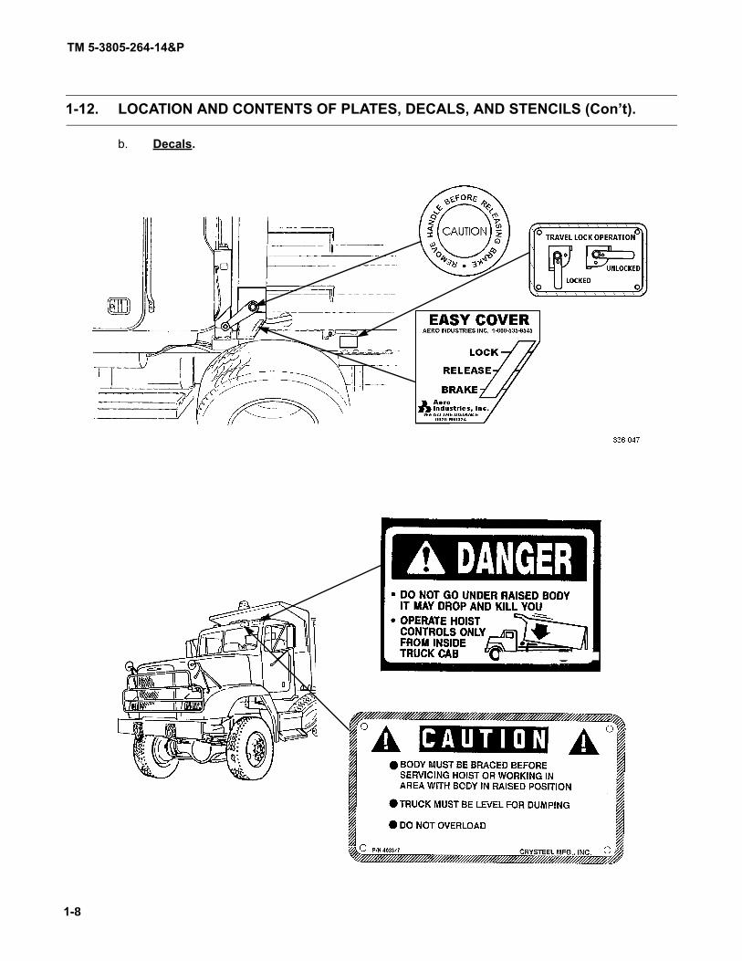
1-12. LOCATION AND CONTENTS OF PLATES, DECALS, AND STENCILS (Con’t).
b. Decals.

TM 5-3805-2 64-14&P
1-9
1-12. LOCATION AND CONTENTS OF PLATES, DECALS, AND STENCILS (Con’t).

TM 5-3805-26 4-14&P
1-10
1-12. LOCATION AND CONTENTS OF PLATES, DECALS, AND STENCILS (Con’t).
M917A1
M917A2

TM 5-3805-264-14&P
1-11
1-13. DIFFERENCES BETWEEN MODELS.
a. The M917A1 and M917A1 w/MCS are the same except for tailgate configuration.
b. The M917A2 and M917A2 w/MCS are the same except for tailgate configuration.
c. The M917A1 and M917A2 tailgate opens from the bottom for normal dumping. Adjustment chainsallow for adjustment of tailgate opening.
d. The M917A1 w/MCS and M917A2 w/MCS tailgate has four electro-pneumatically operated gates,controlled by a control unit mounted on the shift tower inside the cab or by a hand-held remote control that plugsinto a receptacle on either side of the MCS tailgate. This allows controlled spreading of material. The MCS tailgatealso operates as a standard tailgate, opening at the bottom.
1-14. EQUIPMENT DATA.
VEHICLE DIMENSIONS:Overall Length:
M917A1/M917A2 . . . . . . . . . . . . . . . . . . . . . . . . . . . . . . . . . . . . . . . . . . . . . . . . 303.8 in. (771.7 cm)M917A1 w/MCS/M917A2 w/MCS . . . . . . . . . . . . . . . . . . . . . . . . . . . . . . . . . . . . 316.8 in. (804.7 cm)
Overall Height (M917A1 and M917A1 w/MCS) . . . . . . . . . . . . . . . . . . . . . . . . . . . . . 143 in. (363 cm)Overall Height (M917A2 and M917A2 w/MCS) . . . . . . . . . . . . . . . . . . . . . . . . . . . . . 135.5 in. (344 cm)Overall Width (M917A1 and M917A1 w/MCS) . . . . . . . . . . . . . . . . . . . . . . . . . . . . . 102 in. (259 cm)Overall Width (M917A2 and M917A2 w/MCS) . . . . . . . . . . . . . . . . . . . . . . . . . . . . . 103.8 in. (364 cm)Wheelbase (M917A1 and M917A1 w/MCS) . . . . . . . . . . . . . . . . . . . . . . . . . . . . . . . 174 in. (442 cm)Wheelbase (M917A2 and M917A2 w/MCS) . . . . . . . . . . . . . . . . . . . . . . . . . . . . . . . 179 in. (455 cm)Ground Clearance . . . . . . . . . . . . . . . . . . . . . . . . . . . . . . . . . . . . . . . . . . . . . . . . . . . 9 in. (22.9 cm)Turning Diameter. . . . . . . . . . . . . . . . . . . . . . . . . . . . . . . . . . . . . . . . . . . . . . . . . . . . 38.9 ft (11.9 m)
VEHICLE WEIGHTS:GVWR . . . . . . . . . . . . . . . . . . . . . . . . . . . . . . . . . . . . . . . . . . . . . . . . . . . . . . . . . . . . 68,000 lb (30,872 kg)Curb Weight:
M917A1 (Empty) . . . . . . . . . . . . . . . . . . . . . . . . . . . . . . . . . . . . . . . . . . . . . . . . . 29,454 lb (13,372 kg)M917A1 w/MCS (Empty). . . . . . . . . . . . . . . . . . . . . . . . . . . . . . . . . . . . . . . . . . . 31,472 lb (14,288 kg)M917A2 (Empty) . . . . . . . . . . . . . . . . . . . . . . . . . . . . . . . . . . . . . . . . . . . . . . . . . 30,600 lb (13,892 kg)M917A2 w/MCS (Empty). . . . . . . . . . . . . . . . . . . . . . . . . . . . . . . . . . . . . . . . . . . 32,618 lb (14,809 kg)
DUMP BODY:Capacity. . . . . . . . . . . . . . . . . . . . . . . . . . . . . . . . . . . . . . . . . . . . . . . . . . . . . . . . . . . 14 cu yd (10.7 m3)Load Capability . . . . . . . . . . . . . . . . . . . . . . . . . . . . . . . . . . . . . . . . . . . . . . . . . . . . . 18.5 tons
(16.8 metric tons)Length . . . . . . . . . . . . . . . . . . . . . . . . . . . . . . . . . . . . . . . . . . . . . . . . . . . . . . . . . . . . 13.5 ft (411 cm)Width:
Inside. . . . . . . . . . . . . . . . . . . . . . . . . . . . . . . . . . . . . . . . . . . . . . . . . . . . . . . . . . 87 in. (221 cm)Outside . . . . . . . . . . . . . . . . . . . . . . . . . . . . . . . . . . . . . . . . . . . . . . . . . . . . . . . . 96 in. (244 cm)
Height:Sides . . . . . . . . . . . . . . . . . . . . . . . . . . . . . . . . . . . . . . . . . . . . . . . . . . . . . . . . . . 40 in. (102 cm)Front . . . . . . . . . . . . . . . . . . . . . . . . . . . . . . . . . . . . . . . . . . . . . . . . . . . . . . . . . . 62 in. (157 cm)Rear . . . . . . . . . . . . . . . . . . . . . . . . . . . . . . . . . . . . . . . . . . . . . . . . . . . . . . . . . . 48 in. (122 cm)
Cargo Cover:Model . . . . . . . . . . . . . . . . . . . . . . . . . . . . . . . . . . . . . . . . . . . . . . . . . . . . . . . . . M400 AERO, side
mountOperation . . . . . . . . . . . . . . . . . . . . . . . . . . . . . . . . . . . . . . . . . . . . . . . . . . . . . . Crank handle
TM 5-3805-264-14&P
1-12
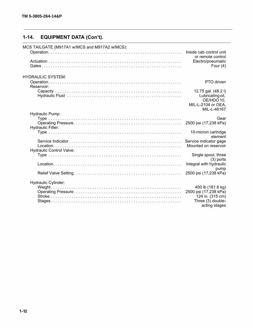
1-14. EQUIPMENT DATA (Con’t).
MCS TAILGATE (M917A1 w/MCS and M917A2 w/MCS):Operation. . . . . . . . . . . . . . . . . . . . . . . . . . . . . . . . . . . . . . . . . . . . . . . . . . . . . . . . . . Inside cab control unit
or remote controlActuation . . . . . . . . . . . . . . . . . . . . . . . . . . . . . . . . . . . . . . . . . . . . . . . . . . . . . . . . . . Electro/pneumaticGates . . . . . . . . . . . . . . . . . . . . . . . . . . . . . . . . . . . . . . . . . . . . . . . . . . . . . . . . . . . . . Four (4)
HYDRAULIC SYSTEM:Operation. . . . . . . . . . . . . . . . . . . . . . . . . . . . . . . . . . . . . . . . . . . . . . . . . . . . . . . . . . PTO drivenReservoir:
Capacity . . . . . . . . . . . . . . . . . . . . . . . . . . . . . . . . . . . . . . . . . . . . . . . . . . . . . . . 12.75 gal. (48.2 l)Hydraulic Fluid . . . . . . . . . . . . . . . . . . . . . . . . . . . . . . . . . . . . . . . . . . . . . . . . . . Lubricating oil,
OE/HDO 10, MIL-L-2104 or OEA,
MIL-L-46167Hydraulic Pump:
Type . . . . . . . . . . . . . . . . . . . . . . . . . . . . . . . . . . . . . . . . . . . . . . . . . . . . . . . . . . GearOperating Pressure . . . . . . . . . . . . . . . . . . . . . . . . . . . . . . . . . . . . . . . . . . . . . . . 2500 psi (17,238 kPa)
Hydraulic Filter:Type . . . . . . . . . . . . . . . . . . . . . . . . . . . . . . . . . . . . . . . . . . . . . . . . . . . . . . . . . . 10-micron cartridge
elementService Indicator . . . . . . . . . . . . . . . . . . . . . . . . . . . . . . . . . . . . . . . . . . . . . . . . . Service indicator gageLocation. . . . . . . . . . . . . . . . . . . . . . . . . . . . . . . . . . . . . . . . . . . . . . . . . . . . . . . . Mounted on reservoir
Hydraulic Control Valve:Type . . . . . . . . . . . . . . . . . . . . . . . . . . . . . . . . . . . . . . . . . . . . . . . . . . . . . . . . . . Single spool, three
(3) portsLocation. . . . . . . . . . . . . . . . . . . . . . . . . . . . . . . . . . . . . . . . . . . . . . . . . . . . . . . . Integral with hydraulic
pumpRelief Valve Setting. . . . . . . . . . . . . . . . . . . . . . . . . . . . . . . . . . . . . . . . . . . . . . . 2500 psi (17,238 kPa)
Hydraulic Cylinder:Weight . . . . . . . . . . . . . . . . . . . . . . . . . . . . . . . . . . . . . . . . . . . . . . . . . . . . . . . . . 400 lb (181.6 kg)Operating Pressure . . . . . . . . . . . . . . . . . . . . . . . . . . . . . . . . . . . . . . . . . . . . . . . 2500 psi (17,238 kPa)Stroke . . . . . . . . . . . . . . . . . . . . . . . . . . . . . . . . . . . . . . . . . . . . . . . . . . . . . . . . . 124 in. (315 cm)Stages. . . . . . . . . . . . . . . . . . . . . . . . . . . . . . . . . . . . . . . . . . . . . . . . . . . . . . . . . Three (3) double-
acting stages

TM 5-3805-264-14&P
1-13
Section III. PRINCIPLES OF OPERATION
Paragraph PageNumber Paragraph Title Number
1-15. Electrical System . . . . . . . . . . . . . . . . . . . . . . . . . . . . . . . . . . . . . . . . . . . . . . . . . . . . . . . . . 1-131-16. Dump Body. . . . . . . . . . . . . . . . . . . . . . . . . . . . . . . . . . . . . . . . . . . . . . . . . . . . . . . . . . . . . . 1-131-17. Hydraulic System . . . . . . . . . . . . . . . . . . . . . . . . . . . . . . . . . . . . . . . . . . . . . . . . . . . . . . . . . 1-16
1-15. ELECTRICAL SYSTEM.
a. The dump body electrical system consists of wiring harnesses that connect to the vehicle’s chassiswiring harnesses.
b. The dump body harnesses connect to:(1) Lights. Taillights and marker clearance lights (one on each side of dump body and three in
light cluster at rear hinge) are located on dump body. Beacon warning light is located on cab shield.(2) Instrument Panel Indicator/Warning Lights and Related Switches. Body Up and Body
(Transport) Lock indicator lights are located on instrument panel in cab. Body Up and Transport Lock switches arelocated on cylinder support frame.
(3) MCS Tailgate (M917A1 w/MCS and M917A2 w/MCS). Solenoid-controlled air cylindersopen and close MCS gates.
1-16. DUMP BODY.
a. Dump Body Assembly. (1) The dump body is a welded assembly of heavy gage steel with bolt-on assemblies and
components. It is 13.5 ft (411 cm) long with 14 cu yd (10.7 m³), 18.5 ton (16.8 metric ton) capacity.(2) The dump body is attached to the truck frame at the rear hinge. Other attachment points
are at the stabilizer and the hydraulic cylinder.(3) An abrasion resistant steel bed resists wear and denting.(4) A bolt-on cab shield protects the cab. The beacon warning light is mounted on the cab
shield.(5) Wooden side boards along the top on both sides of the dump body add height to help pre-
vent spillage when hauling material.(6) The dump body has an interlocking under structure.
b. Stabilizer. (1) A hinged stabilizer, mounted between the truck frame and the dump body, adds stability as
the dump body is raised.(2) Five grease fittings on the stabilizer allow for lubrication.
c. Body Props. (1) Use of body props permit inspection or maintenance to be safely performed underneath an
empty raised dump body.(2) Body props are located on outside of truck frame. When not in use, they are stowed in the
horizontal position.

TM 5-3805-264-14&P
1-14
1-16. DUMP BODY (Con’t).
(3) A grease fitting on each body prop pivot point allows for lubrication.d. Lubrication-Free Bearings. There are composite, lubrication-free bearings with removable pins
at the rear hinge and at the hydraulic cylinder pivot points.e. Transport Lock.
(1) A manually-operated transport lock is mounted on the left side of the dump body, near thefront; it locks and unlocks the dump body from the truck frame. For normal operation, it is unlocked.
(2) The transport lock is placed in the locked position when the dump truck is being lifted andtransported. This actuates a transport lock switch, which disengages the PTO, thereby preventing the PTO fromoperating to power the hydraulic cylinder.
f. Cargo Cover. A cargo cover helps prevent the load from spilling out. It is extended or retractedusing the control handle or the removable crank handle.
g. Tailgate Configuration. The M917A1 and M917A2 differ from the M917A1 w/MCS and M917A2w/MCS in tailgate configuration:
(1) M917A1 and M917A2.
(a) The M917A1 and M917A2 use a nine-panel conventional tailgate that opens from thebottom to dump the load. Adjustment chains, mounted to the tailgate, control the tailgate opening for spreadingoperations.
(b) A tailgate release control valve lever, located on the instrument panel inside the cab,controls the tailgate release air cylinder mounted under the dump body to unlock and lock the tailgate at the bot-tom.
Tailgate
AdjustmentChains
TailgateLockingLinkage

TM 5-3805-264-14&P
1-15
1-16. DUMP BODY (Con’t).
(2) M917A1 w/MCS and M917A2 w/MCS.
(a) The MCS tailgate has four openings (gates) that are electro-pneumatically controlledby a cab control unit or a hand-held remote control. Each gate can be opened and closed independently of theother gates.
(b) Compressed air, plumbed from the chassis’ air system and stored in an air reservoirmounted on the MCS tailgate, opens and closes the gates using solenoid-controlled air cylinders.
(c) Gate opening adjustments are made at each gate, using an adjustment tube with alocking pin that can be moved to different holes in the tube. The lower the pin placement, the larger the gate open-ing. The top pin placement locks the gate closed.
(d) The remote control has a coiled cable that plugs into a receptacle on the left or rightside of the MCS tailgate. It is operated by a person walking alongside the dump body, while the operator inside thecab is dumping the load. When plugged in, the remote control overrides the control unit inside the cab.
(e) The MCS tailgate can also operate as a conventional tailgate, opening from the bot-tom.
RemoteControl
Gate
LockingPin
AdjustmentTube
AirReservoir
Air Lines
AirCylinder
COVER REMOVED FOR CLARITY

TM 5-3805-264-14&P
1-16
1-17. HYDRAULIC SYSTEM.
a. The hydraulic system powers the hydraulic cylinder, which raises and lowers the dump body.
b. Major components of the hydraulic system are:
(1) Hydraulic Pump.
(a) The gear pump is mounted directly to the vehicle PTO. It supplies the system with aworking pressure of 2500 psi (17,238 kPa) with approximately 1200 rpm input speed from the PTO.
(b) There is one port at the rear of the pump. It is connected to the bottom of the reservoirand receives, through a suction hose, hydraulic fluid from the reservoir.
(2) Control Valve.
(a) The control valve is an integral part of the hydraulic pump. It is a single spool type withthe control spool linked mechanically to the hydraulic control lever in the cab.
(b) When the hydraulic control lever is pulled back, the control valve routes hydraulic fluidthrough port B to the hydraulic cylinder. This extends the cylinder and raises the dump body.
(c) When the hydraulic control lever is pushed forward, the control valve routes hydraulicfluid through port A to the hydraulic cylinder. This retracts the hydraulic cylinder and lowers the dump body.
(d) A third control valve port returns hydraulic fluid through the filter and into the reservoir.
(e) The control valve has a relief valve which is set at 2500 psi (17,238 kPa).
(3) Hydraulic Cylinder.
(a) The hydraulic cylinder is a three-stage telescoping cylinder with a 124 in. (315 cm)stroke.
(b) The bottom of the hydraulic cylinder is attached by a pivot pin to the cylinder supportframe.
(c) The collar of the hydraulic cylinder is attached by pivot pins to the dump body insidethe long beam at the front of the dump body.
(d) The pivot pins at the top and bottom of the cylinder allow the cylinder to pivot as it isextended and retracted. Composite lubrication-free bearings at these pivot points ensure smooth, maintenance-free operation.
(4) Hydraulic Filter.
(a) The filter is located on top of the reservoir. It filters hydraulic fluid as it returns to thereservoir through the return line from the control valve.
(b) The filter element is made of 10-micron synthetic material. A filter service indicatorgage indicates when the filter needs replacing.
(c) The filter has a by-pass feature.
(5) Hydraulic Reservoir.
(a) The reservoir is an all steel container with a 12.75 gal. (48.2 l) capacity.
(b) It is mounted upright, bolted to the hydraulic cylinder mount, between the hydrauliccylinder and the vehicle cab.
(c) The fill cap is also a breather and a strainer. It must be kept clean at all times.

TM 5-3805-264-14&P
1-17/(1-18 Blank)
1-17. HYDRAULIC SYSTEM (Con’t).
(d) The oil level in the reservoir can be seen through the sight tube on the outside of thereservoir. An oil level decal, mounted adjacent to the sight tube is marked FULL, ADD 2 QTS, and ADD 1 GAL.
HydraulicControl Lever
Mechanical Linkage
(in cab)PTO
ControlValve
HydPump
Hydraulic
Filter
Cylinder
Oil FlowRaiseLower
HydraulicReservoir


TM 5-3805-264-14&P
2-1
CHAPTER 2OPERATING INSTRUCTIONS
Section I. DESCRIPTION AND USE OF OPERATOR'S CONTROLS AND INDICATORS
Paragraph PageNumber Paragraph Title Number
2-1. Cab-Mounted Controls and Indicators . . . . . . . . . . . . . . . . . . . . . . . . . . . . . . . . . . . . . . . . . 2-12-2. External Controls and Indicators . . . . . . . . . . . . . . . . . . . . . . . . . . . . . . . . . . . . . . . . . . . . . 2-3
2-1. CAB-MOUNTED CONTROLS AND INDICATORS.
Key Control or Indicator Function
1 Hydraulic Control Lever Raises and lowers dump body. Squeeze T-handle together and pull lever back to UP position to raise dump body. Push lever forward to DOWN position to lower dump body. Place in N (Neutral) detent position to stop dump body movement. Lever will not operate to raise dump body if main light switch is in blackout mode.
2 MCS Control Unit (M917A1 w/MCS and M917A2 w/MCS)
Four toggle switches control LEFT, LEFT CENTER, RIGHT CENTER, and RIGHT MCS gates. Move switch(es) forward to OPEN position and rearward to CLOSE position.
3 MCS Indicator Light (M917A1 w/MCS and M917A2 w/MCS)
Red light indicates MCS has power.
1
23
M917A2
1
2
M917A1
3

TM 5-3805-264-14&P
2-2
2-1. CAB-MOUNTED CONTROLS AND INDICATORS (Con’t).
Key Control or Indicators Function
4 Reduce MPH Indicator Light
Red light comes on when vehicle is traveling too fast for tire pressure selected on CTIS.
5 Body Up Indicator Light Red light comes on when dump body is raised. Turns off when dump body is down and in contact with truck frame.
6 Body (Transport) Lock Indicator Light
Red light comes on when dump body is locked to truck frame in preparation for dump truck transport. Alerts driver that dump body will not raise.
7 Tailgate Release Control Valve Lever
Air-activated lever controls tailgate release air cylinder to unlock and lock tailgate. Left position is UNLOCK; right position is LOCK.
8 PTO Switch Engages PTO when turned ON. PTO will not operate unless main light switch is in SER DRIVE or STOP LIGHT position. Light in switch comes on when PTO is ON.
5
6
7
8
4
TM 5-3805-264-14&P
2-3
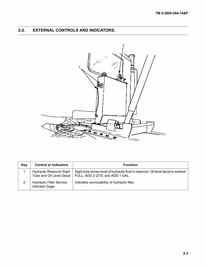
2-2. EXTERNAL CONTROLS AND INDICATORS.
Key Control or Indicators Function
1 Hydraulic Reservoir Sight Tube and Oil Level Decal
Sight tube shows level of hydraulic fluid in reservoir. Oil level decal is marked FULL, ADD 2 QTS, and ADD 1 GAL.
2 Hydraulic Filter Service Indicator Gage
Indicates serviceability of hydraulic filter.
1
2

TM 5-3805-264-14&P
2-4
2-2. EXTERNAL CONTROLS AND INDICATORS (Con’t).
Key Control or Indicators Function
3 Cargo Cover Crank Handle
Turn clockwise to retract cargo cover and uncover load. When not in use, handle is stowed in storage pouch and placed in BII box.
4 Cargo Cover Control Handle
Provides braking action for cargo cover as it extends to cover load. Positions are LOCK, RELEASE, and BRAKE.
5 Transport Lock Locks dump body to truck frame. Unlocked during normal operation. Locked for transporting of dump truck. Unlocked position is at 3 o'clock. Locked position is at 6 o'clock. A locking pin holds transport lock in desired position.
3
4
5

TM 5-3805-264-14&P
2-5/(2-6 Blank)
2-2. EXTERNAL CONTROLS AND INDICATORS (Con’t).
Key Control or Indicators Function
6 MCS Air Reservoir Cable Pull (M917A1 w/MCS and M917A2 w/MCS)
Drains MCS air reservoir, when pulled.
7 Adjustment Tube Locking Pin (M917A1 w/MCS and M917A2 w/MCS)
Controls amount of MCS gate opening. The lower the pin placement, the larger the gate opening. Top pin placement locks gate closed.
8 MCS Remote Control (M917A1 w/MCS and M917A2 w/MCS)
Plugs into receptacle at left or right of MCS tailgate. Four toggle switches control LEFT, LEFT CENTER, RIGHT CENTER, and RIGHT MCS gates. Move switch(es) to OPEN or CLOSED positions. When not in use, remote control is stowed in storage pouch and placed in BII box.
7
6
8

.

TM 5-3805-264-14&P
2-7
Section II. OPERATOR PREVENTIVE MAINTENANCE CHECKSAND SERVICES (PMCS)
Paragraph PageNumber Paragraph Title Number
2-3. General . . . . . . . . . . . . . . . . . . . . . . . . . . . . . . . . . . . . . . . . . . . . . . . . . . . . . . . . . . . . . . . . . 2-72-4. Explanation of Table Entries . . . . . . . . . . . . . . . . . . . . . . . . . . . . . . . . . . . . . . . . . . . . . . . . . 2-72-5. General PMCS Procedures . . . . . . . . . . . . . . . . . . . . . . . . . . . . . . . . . . . . . . . . . . . . . . . . . 2-8Table 2-1. Operator Preventive Maintenance Checks and Services (PMCS) for M917A1,
M917A1 w/MCS, M917A2 and M917A2 w/MCS Dump Body . . . . . . . . . . . . . . . . . . . . 2-10
2-3. GENERAL.
NOTERefer to TM 9-2320-363-10 or TM 9-2320-302-10 for Operator PMCS for the dumptruck chassis.
To ensure that the dump truck is ready for operation at all times, it must be inspected on a regular basisso that defects may be found and corrected before they result in serious damage, equipment failure, or injury topersonnel. Table 2-1 contains systematic instructions on inspections, adjustments, and corrections to be performedby the operator/crew to keep your equipment in good operating condition and ready for its primary mission.
2-4. EXPLANATION OF TABLE ENTRIES.
a. Item Number (Item No.) Column. Numbers in this column are for reference. When completingDA Form 2404 (Equipment Inspection and Maintenance Worksheet), include the item number for the check/serviceindicating a fault. Item numbers also appear in the order that you must perform checks and services for the intervallisted.
b. Interval Column. This column tells you when you must perform the procedure in the procedurecolumn.
(1) Before procedures must be done before you operate the dump truck.(2) During procedures must be done while you are operating the dump truck.(3) After procedures must be done immediately after you have operated the dump truck.(4) Weekly procedures must be done once each week.(5) Monthly procedures must be done once each month.
c. Location, Item to Check/Service Column. This column provides the location and item to bechecked or serviced.
NOTEThe WARNINGs and CAUTIONs appearing in your PMCS table should always be observed.WARNINGs and CAUTIONs appear before applicable procedures. You must observe theseWARNINGs to prevent serious injury to yourself and others, and CAUTIONs to prevent yourequipment from being damaged.
d. Procedure Column. This column gives the procedure you must perform to check or service theitem listed in the Item to Check/Service column to know if the equipment is ready or available for its intended mis-sion or for operation. You must perform the procedure at the time stated in the interval column.

TM 5-3805-264-14&P
2-8
2-4. EXPLANATION OF TABLE ENTRIES (Con’t).
e. Not Fully Mission Capable If: Column. Information in this column tells you what faults will keepyour equipment from being capable of performing its primary mission. If you make check and service proceduresthat show faults listed in this column, do not operate the equipment. Follow standard operating procedures formaintaining the equipment or reporting equipment failure.
2-5. GENERAL PMCS PROCEDURES.
a. Always perform PMCS in the same order so it gets to be a habit. Once you've had some practice,you'll spot anything wrong in a hurry. If the dump truck does not perform as required, refer to the appropriate trou-bleshooting procedure in Chapter 3, Section II.
b. If anything looks wrong and you can't fix it, write it on your DA Form 2404. If you find somethingseriously wrong, IMMEDIATELY report it to your supervisor.
c. Before performing preventive maintenance, read all the checks required for the applicable intervaland prepare all the tools you need to make all the checks. You'll always need a rag (Item 16, Appendix F) or two.
WARNING
Dry cleaning solvent MIL-PRF-680 Type III is an environmentally compliant and lowtoxic material. However, it may be irritating to the eyes and skin. The use of protec-tive gloves and goggles is suggested. Use in well-ventilated area. Keep away fromopen flame and other sources of ignition.
(1) Keep It Clean. Dirt, grease, oil, and debris get in the way and may cover up a serious prob-lem. Clean as you work and as needed. Use dry cleaning solvent (Item 5, Appendix F) on all metal surfaces. Usedetergent (Item 9, Appendix F) and water when you clean rubber or plastic.
(2) Deterioration, Rust, and Corrosion.
(a) Be alert for deterioration of plastic and rubber materials. Report it to your supervisor.
(b) Check metal parts of vehicle for rust and corrosion. If any bare metal or corrosionexists, clean and apply a light coat of oil (Item 15, Appendix F). Report it to your supervisor.
(3) Bolts, Nuts, and Screws. Check bolts, nuts, and screws for obvious looseness, missing,bent, or broken condition. You can't try them all with a tool, of course, but look for chipped paint, bare metal, or rustaround bolt heads. If you find one you think is loose, report it to your supervisor.
(4) Welds. Look for loose or chipped paint, rust, or gaps where parts are welded together. Ifyou find a bad weld, report it to your supervisor.
(5) Electric Wires and Connectors. Look for cracked or broken insulation, bare wires, andloose or broken connectors. Tighten loose connectors and ensure that the wires are in good condition.

TM 5-3805-264-14&P
2-9
2-5. GENERAL PMCS PROCEDURES (Con’t).
(6) Hoses and Fluid Lines. Look for wear, damage, and signs of leaks. Ensure that clampsand fittings are tight. Wet spots indicate leaks, of course, but a stain around a fitting or connector can also mean aleak. If a leak comes from a loose fitting or connector, tighten it. If something is broken or worn out, report it to yoursupervisor.
(7) Fluid Leakage. It is necessary for you to know how fluid leakage affects the status of yourdump truck. The following are definitions of the types/classes of leakage you need to know to be able to determinethe status of your equipment. Learn and be familiar with them, and remember - when it doubt, notify your supervi-sor.
Leakage Definitions for PMCSClass I Leakage indicated by wetness or discoloration, but not great enough to form
drops.Class II Leakage great enough to form drops, but not enough to cause drops to drip
from the item being checked/inspected.Class III Leakage great enough to form drops that fall from the item being checked/
inspected.Operation is allowable with Class I and Class II leakage. WHEN IN DOUBT, NOTIFYYOUR SUPERVISOR. When operating with Class I or Class II leaks, check fluid lev-els more frequently. Class III leaks must be reported immediately to your supervi-sor. Failure to do this will result in damage to vehicle and/or components.

TM 5-3805-264-14&P
2-10
Table 2-1. Operator Preventive Maintenance Checks and Services (PMCS) for M917A1, M917A1 w/MCS, M917A2, and M917A2 w/MCS Dump Body.
Item No. Interval
Location
ProcedureNot Fully Mission
Capable If:
Item ToCheck/Service
WARNING
Unless otherwise specified, performall preventive maintenance checkswith dump truck on level ground,transmission in N (Neutral), parkingbrake set, and engine off. Failure tofollow this warning may result in per-sonnel injury.
NOTE• Review all WARNINGs, CAUTIONs,
and NOTEs before performingPMCS and operating the dumptruck.
• Perform all PMCS checks if:a. You are the assigned operator
but have not operated the dumptruck since the last Weeklyinspection.
b. You are operating the dumptruck for the first time.
FRONT AND LEFT SIDE
1 Before Overall View Check under vehicle for evidence ofhydraulic fluid leakage.
Class III hydraulic fluid leaks areevident.
INSIDE CAB
2 Before Cargo Cover Crank Han-dle
Check that crank handle is stowed instorage pouch in BII box.

TM 5-3805-264-14&P
2-11
Table 2-1. Operator Preventive Maintenance Checks and Services (PMCS) for M917A1, M917A1 w/MCS, M917A2, and M917A2 w/MCS Dump Body (Con’t).
Item No. Interval
Location
ProcedureNot Fully Mission
Capable If:
Item ToCheck/Service
3 Before Startup NOTEDump truck’s chassis air system con-trols both models’ tailgate lockingmechanism and supplies air to theM917A1 w/MCS and M917A2 w/MCStailgate.
a. Start engine and fully pressurize airsystem (TM 9-2320-363-10 or TM 9-2320-302-10).
b. Listen for air leaks on chassis and atrear of dump body.
b. Air leakage is evident.
4 During Dump Body Controls and Indica-tors
a. Check hydraulic control lever (1),MCS control unit (2), and indicatorlight (3) (M917A1 w/MCS andM917A2 w/MCS) for proper opera-tion.
a. Hydraulic control lever mal-functions. MCS control unitmalfunctions and is requiredfor mission.
1
2
3
M917A2
1
2
M917A1
3

TM 5-3805-264-14&P
2-12
Table 2-1. Operator Preventive Maintenance Checks and Services (PMCS) for M917A1, M917A1 w/MCS, M917A2, and M917A2 w/MCS Dump Body (Con’t).
Item No. Interval
Location
ProcedureNot Fully Mission
Capable If:
Item ToCheck/Service
4 (Con’t)
During Dump Body Controls and Indica-tors
b. Monitor body up and body (transport)lock indicator lights (4 and 5), tailgaterelease control valve lever (6), andPTO switch (7) for proper operation.
b. Any indicator light or dumpbody control malfunctions.
5 During Overall Leakage
Be alert for evidence of hydraulic fluidleakage.
Class III hydraulic fluid leaks areevident.
FRONT AND LEFT SIDE
NOTEBegin After PMCS checks with dumpbody lowered and engine off.
6 After Overall View a. Check under vehicle for evidence ofhydraulic fluid leakage.
a. Class III hydraulic fluid leaksare evident.
45
67
M917A2
M917A1
45
6
7
8

TM 5-3805-264-14&P
2-13
Table 2-1. Operator Preventive Maintenance Checks and Services (PMCS) for M917A1, M917A1 w/MCS, M917A2, and M917A2 w/MCS Dump Body (Con’t).
Item No. Interval
Location
ProcedureNot Fully Mission
Capable If:
Item ToCheck/Service
6 (Con’t)
After Overall View b. Check dump body for obvious dam-age that would impair operation: e.g.,missing or damaged cargo covercontrols (10), marker clearance light(11), body prop (14), and adjustmentchain (12) at tailgate.
b. Damage that would impairoperation is evident.
7 After Transport Lock
Check that transport lock (15) is at 3o’clock UNLOCKED position. If locked,remove pin (16), move transport lockcounterclockwise to 3 o’clock position,and reinstall pin.
9
10
11
12
13
14

TM 5-3805-264-14&P
2-14
Table 2-1. Operator Preventive Maintenance Checks and Services (PMCS) for M917A1, M917A1 w/MCS, M917A2, and M917A2 w/MCS Dump Body (Con’t).
Item No. Interval
Location
ProcedureNot Fully Mission
Capable If:
Item ToCheck/Service
7 (Con’t)
After Transport Lock
8 After Cargo Cover a. Operate cargo cover controls (10)and check for smooth operation(paragraph 2-14).
a. Cargo cover does not extendor retract properly.
b. Inspect cargo cover for looseness ofmounting to support frame (9), andcuts or tears to cover. Inspect supportframe for damage.
b. Cargo cover mounting is looseor cover is cut or torn. Supportframe is damaged.
c. After operating cargo cover controls(10), ensure that crank handle isstowed in storage pouch in BII box.
9 After Tailgate Locking Linkage
Check for damage to tailgate lockinglinkage (13).
Tailgate locking linkage is dam-aged.
15
16

TM 5-3805-264-14&P
2-15
Table 2-1. Operator Preventive Maintenance Checks and Services (PMCS) for M917A1, M917A1 w/MCS, M917A2, and M917A2 w/MCS Dump Body (Con’t).
Item No. Interval
Location
ProcedureNot Fully Mission
Capable If:
Item ToCheck/Service
REAR AND RIGHT SIDE
10 After Overall View a. Check under vehicle for evidence ofhydraulic fluid leakage.
a. Class III hydraulic fluid leaksare evident.
b. Check dump body for obvious dam-age that would impair operation: e.g.,missing or damaged marker clear-ance lights (11), taillight (17), bodyprop (14), and adjustment chain (12)at tailgate.
b. Damage that would impairoperation is evident.
11 After Tailgate Locking Linkage
Check for damage to tailgate lockinglinkage (13).
Tailgate locking linkage is dam-aged.
NOTEPerform the following After PMCS checks with engine on and air system fully pressurized.
12 After Tailgate Release Lever
Operate tailgate release control valvelever (6) inside cab (paragraph 2-1).Check that tailgate unlocks and locksproperly.
Tailgate will not unlock or lock.
1117
11 13
14
12

TM 5-3805-264-14&P
2-16
Table 2-1. Operator Preventive Maintenance Checks and Services (PMCS) for M917A1, M917A1 w/MCS, M917A2, and M917A2 w/MCS Dump Body (Con’t).
Item No. Interval
Location
ProcedureNot Fully Mission
Capable If:
Item ToCheck/Service
12 (Con’t)
After Tailgate Release Lever
WARNING
To prevent burns, use caution whenremoving fill cap of hydraulic reser-voir when hydraulic fluid is hot. Avoidcontact with hot hydraulic oil. Useextreme care when filling hydraulicreservoir. Failure to follow this warn-ing may result in injury to personnel.
13 After Hydraulic Reservoir
a. With engine off and dump body low-ered, check sight tube (18) to deter-mine level of hydraulic oil in reservoir(21). Level should be even with FULLmark on oil level decal (20). If level islow, remove fill cap (19). Remove anydebris from strainer with a clean rag.Add oil (Item 13 or 14, Appendix F)through fill cap opening until level iseven with FULL mark on decal. Installfill cap (Chapter 3, Section I).
6
M917A2 Panel Shown
19
20
21
18

TM 5-3805-264-14&P
2-17
Table 2-1. Operator Preventive Maintenance Checks and Services (PMCS) for M917A1, M917A1 w/MCS, M917A2, and M917A2 w/MCS Dump Body (Con’t).
Item No. Interval
Location
ProcedureNot Fully Mission
Capable If:
Item ToCheck/Service
13 (Con’t)
After Hydraulic Reservoir
b. Run engine at idle speed and engagePTO (TM 9-2320-363-10 or TM 9-2320-302-10). Check filter serviceindicator gage (22). If gage needle isin RED zone, hydraulic oil filter ele-ment needs replacing. Notify yoursupervisor.
22

TM 5-3805-264-14&P
2-18
Table 2-1. Operator Preventive Maintenance Checks and Services (PMCS) for M917A1, M917A1 w/MCS, M917A2, and M917A2 w/MCS Dump Body (Con’t).
Item No. Interval
Location
ProcedureNot Fully Mission
Capable If:
Item ToCheck/Service
14 After MCSTailgate (M917A1w/MCS and M917A2w/MCS)
a. Remove locking pins (24) from tophole in adjustment tubes (25) andplace in bottom hole.
24
25
26

TM 5-3805-264-14&P
2-19
Table 2-1. Operator Preventive Maintenance Checks and Services (PMCS) for M917A1, M917A1 w/MCS, M917A2, and M917A2 w/MCS Dump Body (Con’t).
Item No. Interval
Location
ProcedureNot Fully Mission
Capable If:
Item ToCheck/Service
14 (Con’t)
After MCSTailgate (M917A1w/MCS and M917A2w/MCS)
b. Operate MCS control unit (2) insidecab (paragraph 2-1). Check thatappropriate MCS gate (26) opensand closes as each toggle switch isoperated.
b. MCS control unit does notopen or close gates and isrequired for mission.
2
M917A2
2
M917A1

TM 5-3805-264-14&P
2-20
Table 2-1. Operator Preventive Maintenance Checks and Services (PMCS) for M917A1, M917A1 w/MCS, M917A2, and M917A2 w/MCS Dump Body (Con’t).
Item No. Interval
Location
ProcedureNot Fully Mission
Capable If:
Item ToCheck/Service
14 (Con’t)
After MCSTailgate (M917A1w/MCS and M917A2w/MCS)
WARNING
When connected, MCS remote controloverrides cab control unit. Whenremote control is disconnected, cabcontrol activates. To avoid inadvertentopening or closing of gates, ALWAYScheck gate positions and position oftoggle switches on both cab andremote controls before plugging in orunplugging remote control. Toggleswitches should be in CLOSED posi-tion. Failure to follow this warningmay cause personnel injury.c. Plug MCS remote control (28) into
receptacle (29) at either side of MCStailgate (23). Check that appropriateMCS gate (26) opens and closes aseach toggle switch (27) is operated.
c. MCS remote control does notwork and is required for mis-sion.
d. Remove locking pins (24) from bot-tom hole and install in top hole ofadjustment tubes (25).
29
28
27
24
25
23
26

TM 5-3805-264-14&P
2-21
Table 2-1. Operator Preventive Maintenance Checks and Services (PMCS) for M917A1, M917A1 w/MCS, M917A2, and M917A2 w/MCS Dump Body (Con’t).
Item No. Interval
Location
ProcedureNot Fully Mission
Capable If:
Item ToCheck/Service
WARNING
NEVER work under a raised dumpbody unless it is secured in the raisedposition with body props and dumpbody is EMPTY. Failure to follow thiswarning may result in death or injuryto personnel.
15 After Body Props Raise dump body and support with bodyprops (paragraph 2-15). Check that bodyprops function properly and do not bind.
Body props are damaged or can-not be installed to safely supportdump body.
NOTEPerform the following After PMCScheck with engine off.
16 After AirReservoir (M917A1w/MCS and M917A2w/MCS)
Pull cable pull (30) and drain air reser-voir. Release cable pull when all air hasdrained.
30

TM 5-3805-264-14&P
2-22
Table 2-1. Operator Preventive Maintenance Checks and Services (PMCS) for M917A1, M917A1 w/MCS, M917A2, and M917A2 w/MCS Dump Body (Con’t).
Item No. Interval
Location
ProcedureNot Fully Mission
Capable If:
Item ToCheck/Service
WARNING
NEVER work under a raised dumpbody unless it is secured in the raisedposition with body props and dumpbody is EMPTY. Failure to follow thiswarning may result in death or injuryto personnel.
17 Weekly Hydraulic System
a. Raise dump body and support withbody props (paragraph 2-15).
b. Inspect hydraulic cylinder (31),hydraulic reservoir (21), and hydrau-lic lines and fittings for loose mount-ing, leaks or damaged components.
b. Damage to components orClass III hydraulic fluid leaksare evident.
c. Remove body props and lower dumpbody (paragraph 2-15).
31
21

TM 5-3805-264-14&P
2-23
Table 2-1. Operator Preventive Maintenance Checks and Services (PMCS) for M917A1, M917A1 w/MCS, M917A2, and M917A2 w/MCS Dump Body (Con’t).
Item No. Interval
Location
ProcedureNot Fully Mission
Capable If:
Item ToCheck/Service
WARNING
NEVER work under a raised dumpbody unless it is secured in the raisedposition with body props and dumpbody is EMPTY. Failure to follow thiswarning may result in death or injuryto personnel.
18 Monthly Body Props a. Raise dump body and support onbody props (paragraph 2-15).
a. Body props are damaged orcannot be installed to safelysupport dump body.
b. Apply grease (Item 11, Appendix F)to grease fitting (32) on each bodyprop (14).
32
14

TM 5-3805-264-14&P
2-24
Table 2-1. Operator Preventive Maintenance Checks and Services (PMCS) for M917A1, M917A1 w/MCS, M917A2, and M917A2 w/MCS Dump Body (Con’t).
Item No. Interval
Location
ProcedureNot Fully Mission
Capable If:
Item ToCheck/Service
19 Monthly Stabilizer Apply grease (Item 11, Appendix F) tofive grease fittings (33) on stabilizer (34).There are two grease fittings at top andbottom crosses and one grease fitting atcenter hinge.
20 Monthly Transport Lock
Apply grease (Item 11, Appendix F) tofour transport lock grease fittings (35).
34
33
33
33
35
35
35

TM 5-3805-264-14&P
2-25/(2-26 Blank)
Table 2-1. Operator Preventive Maintenance Checks and Services (PMCS) for M917A1, M917A1 w/MCS, M917A2, and M917A2 w/MCS Dump Body (Con’t).
Item No. Interval
Location
ProcedureNot Fully Mission
Capable If:
Item ToCheck/Service
21 Monthly Tailgate Locking Linkage
a. Apply grease (Item 11, Appendix F)to tailgate locking linkage grease fit-ting (36).
b. Remove body props and lower dumpbody (paragraph 2-15).
22 Monthly Tailgate Hinge Pins
Apply grease (Item 11, Appendix F) toeach tailgate hinge pin grease fitting(37).
36
37


TM 5-3805-264-14&P
2-27
Section III. OPERATION UNDER USUAL CONDITIONS
Paragraph PageNumber Paragraph Title Number
2-6. Scope . . . . . . . . . . . . . . . . . . . . . . . . . . . . . . . . . . . . . . . . . . . . . . . . . . . . . . . . . . . . . . . . . . 2-272-7. Preparing to Load Dump Body . . . . . . . . . . . . . . . . . . . . . . . . . . . . . . . . . . . . . . . . . . . . . . . 2-272-8. Loading Dump Body . . . . . . . . . . . . . . . . . . . . . . . . . . . . . . . . . . . . . . . . . . . . . . . . . . . . . . . 2-282-9. Transporting Load. . . . . . . . . . . . . . . . . . . . . . . . . . . . . . . . . . . . . . . . . . . . . . . . . . . . . . . . . 2-292-10. Dumping Load . . . . . . . . . . . . . . . . . . . . . . . . . . . . . . . . . . . . . . . . . . . . . . . . . . . . . . . . . . . 2-302-11. Adjusting Tailgate Opening. . . . . . . . . . . . . . . . . . . . . . . . . . . . . . . . . . . . . . . . . . . . . . . . . . 2-362-12. Adjusting MCS Gate Openings (M917A1 w/MCS and M917A2 w/MCS) . . . . . . . . . . . . . . . 2-372-13. Controlled Spreading (M917A1 w/MCS and M917A2 w/MCS). . . . . . . . . . . . . . . . . . . . . . . 2-382-14. Operating Cargo Cover . . . . . . . . . . . . . . . . . . . . . . . . . . . . . . . . . . . . . . . . . . . . . . . . . . . . 2-402-15. Operating Body Props . . . . . . . . . . . . . . . . . . . . . . . . . . . . . . . . . . . . . . . . . . . . . . . . . . . . . 2-42
2-6. SCOPE.
NOTERefer to TM 9-2320-363-10 or TM 9-2320-302-10 for operating instructions for thedump truck chassis.
a. This section provides instructions on operating the M917A1, M917A1 w/MCS, M917A2, andM917A2 w/MCS dump truck body under usual conditions.
b. Refer to Section IV of this chapter for operating instructions under unusual conditions.c. Before, during, and after operation, perform applicable Operator PMCS (Chapter 2, Section II).
2-7. PREPARING TO LOAD DUMP BODY.
a. As required, clean dump body of material previously carried (paragraph 3-5).b. Ensure that tailgate is closed (paragraph 2-1). If operating an M917A1 w/MCS or M917A2 w/MCS,
ensure that MCS gates are closed (paragraph 2-1 or 2-2).c. With engine running, ensure that dump body is fully lowered by checking body up indicator light on
instrument panel (paragraph 2-1). Light must be off. Lower dump body, if raised (paragraph 2-10).
WARNING
DO NOT park on a slope. Park on level ground only. Parking on a slope could causeload to shift and dump truck to tip over. Failure to follow this warning may result indeath or injury to personnel or damage to equipment.
d. Position dump body for loading:(1) Position dump truck on firm level ground at a location convenient for loading.(2) If dump body is to be loaded using a hopper, check clearance before pulling under hopper.
Position dump truck with hopper above center of dump body.

TM 5-3805-264-14&P
2-28
2-7. PREPARING TO LOAD DUMP BODY (Con’t).
WARNING
• Use extreme care when handling heavy parts. Lifting cables, chains, hooks, andslings must be in good condition and of suitable capacity. Keep clear of partssupported only by lifting device. Failure to follow this warning may result indeath or injury to personnel and damage to equipment.
• Dump body side boards weigh approximately 65 lb (30 kg) each. Two personnelare required to install or remove side boards. Failure to follow this warning maycause injury to personnel.
NOTE
Dump truck operator should get assistance from loading vehicle operator toremove dump body side boards.
(3) Remove dump body side boards, if necessary.
WARNING
Ensure that parking brake is set before loading dump truck (TM 9-2320-363-10 or TM9-2320-302-10). If parking brake is not set, dump truck could roll or shift position.Failure to follow this warning may result in death or injury to personnel or damageto equipment.
e. Set parking brake (TM 9-2320-363-10 or TM 9-2320-302-10).
f. Disengage PTO, if engaged (TM 9-2320-363-10 or TM 9-2320-302-10).
2-8. LOADING DUMP BODY.
WARNING
• Stand clear of dump body during loading operation. Material being loaded couldfall on personnel standing too close. Failure to follow this warning may result indeath or injury to personnel.
• Hearing protection is required when performing loading operations. Failure tofollow this warning may result in injury to personnel.
a. Clear all personnel from around dump truck.

TM 5-3805-264-14&P
2-29
2-8. LOADING DUMP BODY (Con’t).
CAUTION
Load dump body evenly. Material must not be heaped so high that it spills oversides of body. DO NOT overload. Failure to follow this caution may damage equip-ment.
b. Load dump body. Ensure that material is loaded evenly.c. Cover load with cargo cover (paragraph 2-14).
2-9. TRANSPORTING LOAD.
CAUTION
DO NOT transport load with PTO engaged. Always disengage PTO when hydraulicpower is no longer needed. If PTO is engaged while dump truck is transporting aload, severe damage to hydraulic pump, PTO or transmission will result.
a. Avoid sudden stops, turns or accelerations. This may cause load to shift.b. During off-road operation, avoid terrain with side slope.c. Use vehicle's CTIS to change tire pressures as road conditions change. Use CTIS in EMER
(emergency) mode if dump truck becomes stuck (TM 9-2320-363-10 or TM 9-2320-302-10).

TM 5-3805-264-14&P
2-30
2-10. DUMPING LOAD.
WARNING
• Hearing protection is required when performing dumping operations. Failure tofollow this warning may result in injury to personnel.
• DO NOT attempt to dump in high wind. High winds may disperse aggregate.High winds may also cause dump truck to roll over when dump body is raised.Failure to follow this warning may result in death or injury to personnel or dam-age to equipment.
• Stay at controls while dumping. If dump body leans or shifts to one side, lower itimmediately and check for one of the following:- underinflated or flat tires- tires sinking in soft soil- load shifting to one side of body- high or gusty wind- weak or broken leaf springIf one of these or any other problems are found, do not continue dumping untilthe problem is corrected. Failure to follow this warning may result in death orinjury to personnel or damage to equipment.
• DO NOT spread or dump payload with dump truck facing a steep upgrade or asteep side slope. Dump truck may tip over backward or sideways. Failure to fol-low this warning may result in death or injury to personnel or damage to equip-ment.
• DO NOT park on a slope. Park on level ground only. Parking on a slope couldcause load to shift and dump truck to tip over. Failure to follow this warningmay result in death or injury to personnel or damage to equipment.
NOTE
• This paragraph describes dumping a load through the tailgate opening of eithermodel dump truck.
• For instructions on controlled spreading using the M917A1 w/MCS and M917A2w/MCS gates, refer to paragraph 2-13.
• Assistance is required for this operation. Driver inside cab operates dumpingcontrols. Assistant driver monitors area around dump body.
a. Preparing to Dump.(1) Position dump truck on level ground. Set parking brake (TM 9-2320-363-10 or TM 9-2320-
302-10).(2) Walk around dump truck and check the following:
(a) Wheels are on firm level ground.(b) Dump truck is not leaning to one side.(c) Area behind tailgate is clear.(d) Overhead clearance is sufficient.(e) Transport lock is unlocked (3 o'clock position) (paragraph 2-2).
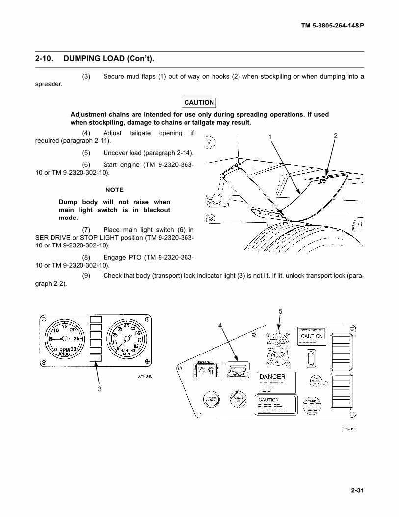
TM 5-3805-264-14&P
2-31
2-10. DUMPING LOAD (Con’t).
(3) Secure mud flaps (1) out of way on hooks (2) when stockpiling or when dumping into aspreader.
CAUTION
Adjustment chains are intended for use only during spreading operations. If usedwhen stockpiling, damage to chains or tailgate may result.
(4) Adjust tailgate opening ifrequired (paragraph 2-11).
(5) Uncover load (paragraph 2-14).
(6) Start engine (TM 9-2320-363-10 or TM 9-2320-302-10).
NOTE
Dump body will not raise whenmain light switch is in blackoutmode.
(7) Place main light switch (6) inSER DRIVE or STOP LIGHT position (TM 9-2320-363-10 or TM 9-2320-302-10).
(8) Engage PTO (TM 9-2320-363-10 or TM 9-2320-302-10).
(9) Check that body (transport) lock indicator light (3) is not lit. If lit, unlock transport lock (para-graph 2-2).
1 2
3
4
5

TM 5-3805-264-14&P
2-32
2-10. DUMPING LOAD (Con’t).
WARNING
NEVER unlock tailgate or operate MCS gates, or operate hydraulic control lever incab without first ensuring that all personnel are clear of dump body. Failure to fol-low this warning may result in injury to personnel.
CAUTION
Ensure that tailgate latches are fully opened before raising dump body. Failure tofollow this caution could result in damage to equipment.
(10) Slide tailgate release control valve lever (4) left to UNLOCK position. Check that tailgate isunlatched.
b. Raising Dump Body.
WARNING
• NEVER raise dump body more than half way with tailgate or MCS tailgateclosed. If dump body is raised fully without opening tailgate, dump truck centerof gravity will shift rearward. Dump truck could tip, causing injury to personnelor damage to equipment.
• NEVER raise dump body without first checking for overhead obstructions suchas trees and power lines. Ensure that overhead clearance is sufficient. Failureto follow this warning may cause death or injury to personnel.
(1) Sound horn if tactical situation permits.
3
4

TM 5-3805-264-14&P
2-33
2-10. DUMPING LOAD (Con’t).
NOTESpeed of dump body movement when it is being raised may be controlled withaccelerator pedal.
(2) Squeeze T-handle together and pull hydraulic control lever (6) back to UP position. Bodyup indicator light (3) should come on as dump body is raised.
WARNING
DO NOT try to loosen a sticky load by pulling forward or backward and brakingabruptly. Injury to personnel or damage to equipment may result.
NOTEDump body will stop automatically when hydraulic cylinder is fully extended orwhen hydraulic control lever is placed in N (Neutral) position.
(3) Return hydraulic control lever (6) to N (Neutral) position when dump body is fully raised orhas reached desired height.
6
M917A2
6
M917A1

TM 5-3805-264-14&P
2-34
2-10. DUMPING LOAD (Con’t).
c. Lowering Dump Body.
CAUTION
Dump body must be lowered onto truck frame with engine running at idle speed.Failure to follow this caution may damage hydraulic cylinder or dump body.
(1) With engine at idle speed, squeeze T-handle together and push hydraulic control lever (6)forward to DOWN position. Body up indicator light (7) should turn off when dump body contacts truck frame.
74
5
M917A2
M917A1
3
4

TM 5-3805-264-14&P
2-35
2-10. DUMPING LOAD (Con’t).
(2) Return hydraulic control lever (6) to N (Neutral) position.
d. After Dumping.
CAUTION
Always disengage PTO when hydraulic power is no longer needed. If PTO isengaged while dump truck is transporting a load, severe damage to hydraulicpump, PTO or transmission will result.
(1) Disengage PTO (TM 9-2320-363-10 or TM 9-2320-302-10).
(2) Turn off main light switch (5).(3) Slide tailgate release control
valve lever (4) right to LOCK position.(4) As required, release mud flaps
(1) from stowed position on hooks (2).
.
6
M917A2
6
M917A1
12

TM 5-3805-264-14&P
2-36
2-11. ADJUSTING TAILGATE OPENING.
WARNING
Use extreme caution when adjusting tailgate opening. NEVER adjust tailgate open-ing when tailgate is open. Failure to follow this warning could result in injury to per-sonnel.
CAUTION
Adjustment chains are intended for use only during spreading operations. If usedwhen stockpiling, damage to chains or tailgate may result.
NOTETo reduce interference between tailgate chain and tailgate locking linkage, chainmust pass through chain latch from the outside inward.
a. In preparation for dumping load, with tailgate closed, lift chain out of slot (2) of chain latch (1).
NOTEAdjustment must be made equally on both sides of tailgate.
b. Lengthen or shorten chain length by pulling links through chain latch (1).c. Secure adjustment by sliding chain into slot (2).
1
2

TM 5-3805-264-14&P
2-37
2-12. ADJUSTING MCS GATE OPENINGS (M917A1 W/MCS AND M917A2 W/MCS).
WARNING
• Use extreme caution when adjusting MCS gate openings. NEVER adjust gateopenings when gates are open. Failure to follow this warning could result ininjury to personnel.
• Keep hands and feet away from gate openings at all times. Failure to follow thiswarning could result in injury to personnel.
NOTEAdjust MCS gate openings with engine on and MCS air system pressurized.
a. When dump truck is transporting a load or when it is parked, MCS gates must be kept locked.Gates are locked by placing locking pins (2) in top hole in adjustment tubes (1).
b. In preparation for controlled spreading, with dump body down and MCS gates closed, removelocking pins (2) from top hole in adjustment tubes (1).
CAUTION
Outer right and outer left side adjustment tube locking pins must be installed withpin heads to outside. If incorrectly installed, end of pins will protrude and becomebent.
NOTETo achieve desired spreading pattern, each gate opening can be adjusted individu-ally.
c. Install locking pin (2) in desired hole in adjustment tube (1). The lower the pin placement, thelarger the gate opening.
d. When controlled spreading is completed, after gates have been closed and dump body is down,return locking pins (2) to top hole in adjustment tubes (1) to lock gates closed.
1
1
2
2

TM 5-3805-264-14&P
2-38
2-13. CONTROLLED SPREADING (M917A1 W/MCS AND M917A2 W/MCS).
WARNING
• DO NOT connect or disconnect MCS remote control when dump body is beingraised or lowered. Failure to follow this warning may cause personnel injury.
• When connected, MCS remote control overrides cab control unit. When remotecontrol is disconnected, cab control activates. To avoid inadvertent opening orclosing of gates, ALWAYS check gate positions and position of toggle switcheson both cab and remote controls before plugging in or unplugging remote con-trol. Toggle switches should be in CLOSED position. Failure to follow this warn-ing may cause personnel injury.
• DO NOT spread or dump payload with dump truck facing a steep upgrade or asteep side slope. Dump truck may tip over backward or sideways. Failure to fol-low this warning may result in death or injury to personnel or damage to equip-ment.
• DO NOT stand or walk behind dump truck when it is dumping or in raised posi-tion. When using MCS remote control, always walk or stand to side of dumpbody. Failure to follow this warning may result in personnel injury.
• Keep hands and feet away from gate openings at all times. Failure to follow thiswarning could result in injury to personnel.
NOTE
• Operation requires two personnel, driver and assistant driver. • Follow general dumping instructions in paragraph 2-10, with minor differences.
Differences will be pointed out as they occur.
a. Follow instructions in paragraph 2-10 to prepare to dump, except for the following steps:
(1) DO NOT unlock tailgate.
(2) Adjust MCS gate openings (paragraph 2-12).
b. Ensure that toggle switches on MCS control unit inside cab are in CLOSE position (paragraph 2-1).
c. Remove MCS remote control (1) from stowage. Ensure that toggle switches (5) are in CLOSEDposition. Plug remote control into receptacle (2) at right or left side of MCS tailgate (3).
d. Move toggle switches (5) to OPEN position. Depending on desired spreading pattern, all gates (4)or selected gates may be opened.
e. Raise dump body 2-3 ft (61-91 cm) and stop. Material should begin to spill out through gates (4).
f. Have driver pull forward with transmission in first gear (TM 9-2320-363-10 or TM 9-2320-302-10).Maintain a steady speed not to exceed 3 mi/h (5 km/h). Have assistant driver check thickness of dumped materialto determine if gate openings need adjusting.
g. If adjustment is needed, stop dump truck, lower dump body, close gates (4), place transmission inN (Neutral), and set parking brake. Adjust MCS gate openings (paragraph 2-12).
h. Maintain a steady speed until all material has been spread. Raise dump body periodically to keepmaterial flowing evenly through gates (4).

TM 5-3805-264-14&P
2-39
2-13. CONTROLLED SPREADING (M917A1 W/MCS AND M917A2 W/MCS) (Con’t).
WARNING
Care must be exercised when using the Material Control System (MCS). In the eventmaterial fails to flow through gates, open gate using open control and clear jamusing BII shovel. DO NOT attempt to clear material using your hands or feet. Failureto follow this warning may cause injury to personnel.
i. If material becomes jammed in gates, open gate and clear jam with BII shovel.j. Close gates (4) by moving toggle switches (5) to CLOSED position.k. Lower dump body (paragraph 2-10). l. Unplug MCS remote control (1) from receptacle (2). Stow remote control in storage pouch and
place in BII box.m. Lock gates closed by returning adjustment tube locking pins to top hole in tubes (paragraph 2-12).n. Perform after dumping steps, as applicable (paragraph 2-10).
1
2
4
3
5
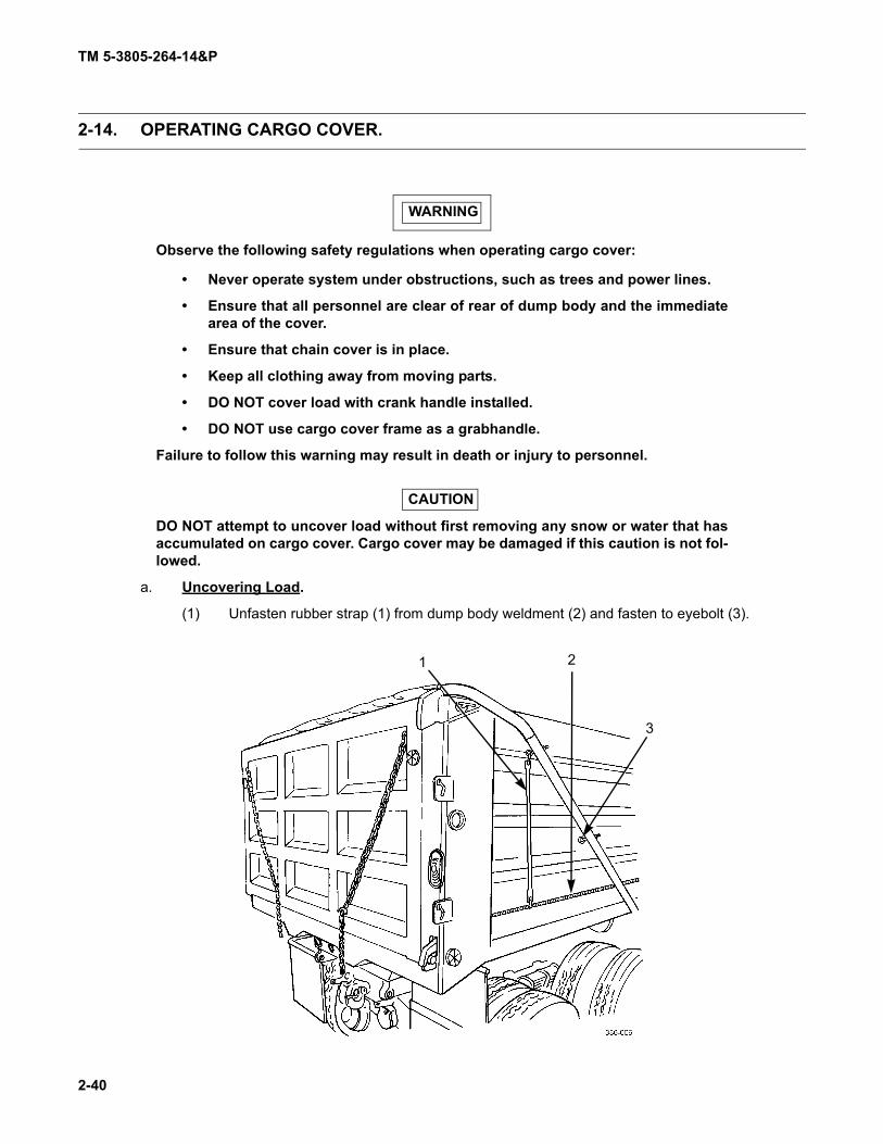
TM 5-3805-264-14&P
2-40
2-14. OPERATING CARGO COVER.
WARNING
Observe the following safety regulations when operating cargo cover:
• Never operate system under obstructions, such as trees and power lines.
• Ensure that all personnel are clear of rear of dump body and the immediatearea of the cover.
• Ensure that chain cover is in place.
• Keep all clothing away from moving parts.
• DO NOT cover load with crank handle installed.
• DO NOT use cargo cover frame as a grabhandle.
Failure to follow this warning may result in death or injury to personnel.
CAUTION
DO NOT attempt to uncover load without first removing any snow or water that hasaccumulated on cargo cover. Cargo cover may be damaged if this caution is not fol-lowed.
a. Uncovering Load.
(1) Unfasten rubber strap (1) from dump body weldment (2) and fasten to eyebolt (3).
1 2
3

TM 5-3805-264-14&P
2-41
2-14. OPERATING CARGO COVER (Con’t).
(2) Remove crank handle (4) from storage pouch in BII box.
(3) Install crank handle (4) on crank shaft (5). Turn handle clockwise to roll up cargo cover.Stop at any time and mechanism will hold cover in place.
(4) Stop cranking when cargo cover is completely rolled up.
(5) Remove crank handle (4) and stow.
b. Covering Load.
WARNING
DO NOT cover load with crank handle installed. Failure to follow this warning mayresult in injury to personnel.
(1) Ensure that crank handle (4) is NOT installed.
(2) Quickly move cargo cover control handle (6) to farthest down BRAKE position.
CAUTION
DO NOT let go of cargo cover control handle until cargo cover is fully over load.Handle provides braking action for cargo cover swing. If you let go of handle beforecargo cover is over load, damage to crank assembly may result.
(3) Carefully lift cargo cover control handle (6) toward RELEASE position until cargo coverbegins to move. Keep hand on handle so that cover moves slowly. If cargo cover moves too fast, move handledown slightly to apply brakes.
(4) When cargo cover is fully over load, release cargo cover control handle (6). Handle willreturn to top LOCK position.
(5) Unfasten rubber strap (1) from eyebolt (3) and fasten to dump body weldment (2).
4 6
5
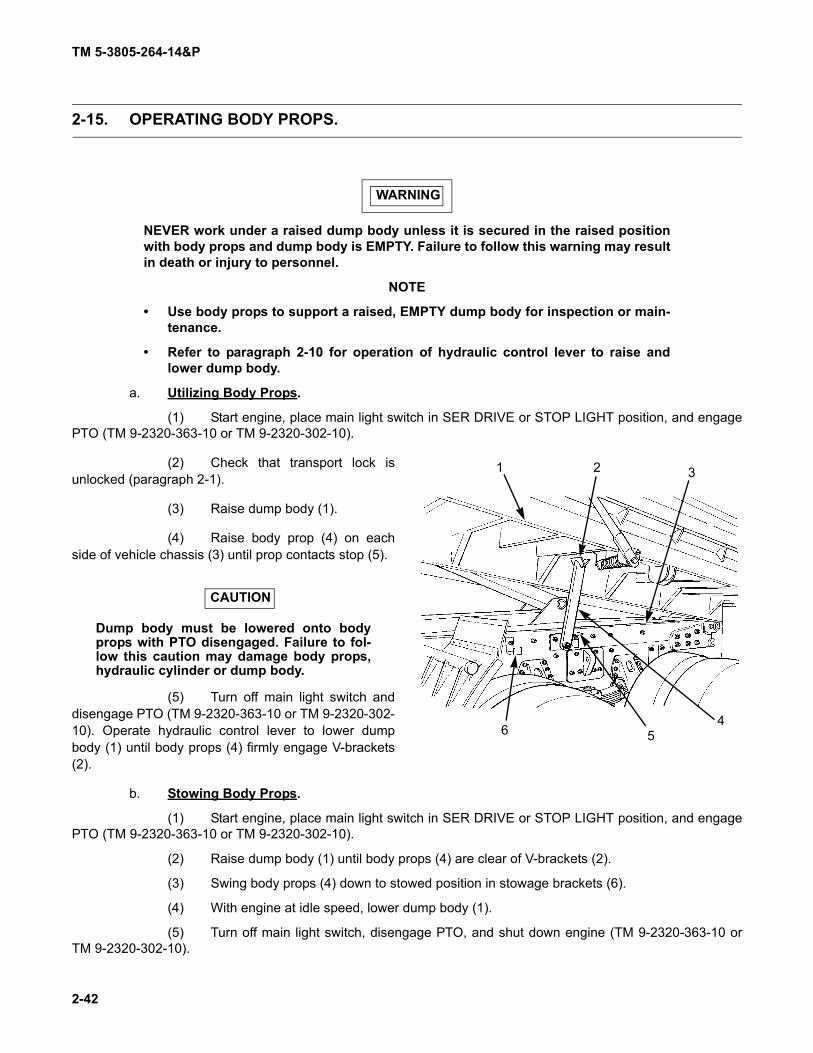
TM 5-3805-264-14&P
2-42
2-15. OPERATING BODY PROPS.
WARNING
NEVER work under a raised dump body unless it is secured in the raised positionwith body props and dump body is EMPTY. Failure to follow this warning may resultin death or injury to personnel.
NOTE
• Use body props to support a raised, EMPTY dump body for inspection or main-tenance.
• Refer to paragraph 2-10 for operation of hydraulic control lever to raise andlower dump body.
a. Utilizing Body Props.
(1) Start engine, place main light switch in SER DRIVE or STOP LIGHT position, and engagePTO (TM 9-2320-363-10 or TM 9-2320-302-10).
(2) Check that transport lock isunlocked (paragraph 2-1).
(3) Raise dump body (1).
(4) Raise body prop (4) on eachside of vehicle chassis (3) until prop contacts stop (5).
CAUTION
Dump body must be lowered onto bodyprops with PTO disengaged. Failure to fol-low this caution may damage body props,hydraulic cylinder or dump body.
(5) Turn off main light switch anddisengage PTO (TM 9-2320-363-10 or TM 9-2320-302-10). Operate hydraulic control lever to lower dumpbody (1) until body props (4) firmly engage V-brackets(2).
b. Stowing Body Props.
(1) Start engine, place main light switch in SER DRIVE or STOP LIGHT position, and engagePTO (TM 9-2320-363-10 or TM 9-2320-302-10).
(2) Raise dump body (1) until body props (4) are clear of V-brackets (2).
(3) Swing body props (4) down to stowed position in stowage brackets (6).
(4) With engine at idle speed, lower dump body (1).
(5) Turn off main light switch, disengage PTO, and shut down engine (TM 9-2320-363-10 orTM 9-2320-302-10).
1 2 3
456

TM 5-3805-264-14&P
2-43/(2-44 Blank)
Section IV. OPERATION UNDER UNUSUAL CONDITIONS
Paragraph PageNumber Paragraph Title Number
2-16. Operation in Windy Weather. . . . . . . . . . . . . . . . . . . . . . . . . . . . . . . . . . . . . . . . . . . . . . . . . 2-432-17. Operation in Rainy or Snowy Weather . . . . . . . . . . . . . . . . . . . . . . . . . . . . . . . . . . . . . . . . . 2-432-18. Operation in Cold Weather . . . . . . . . . . . . . . . . . . . . . . . . . . . . . . . . . . . . . . . . . . . . . . . . . . 2-43
2-16. OPERATION IN WINDY WEATHER.
WARNING
DO NOT attempt to dump in high wind. High winds may disperse aggregate, caus-ing injury to personnel or damage to equipment. High winds may also cause dumptruck to roll over when bed is raised. Failure to follow this warning could result indeath or injury to personnel or damage to equipment.
In moderate winds use cargo cover to keep material from blowing out of dump bed.
2-17. OPERATION IN RAINY OR SNOWY WEATHER.
a. In rainy or snowy weather use cargo cover to keep loads dry. Wet loads may stick, making dump-ing difficult.
CAUTION
DO NOT leave cargo cover extended over an empty dump body. DO NOT attempt touncover load without first removing any snow or water that has accumulated oncargo cover. Cargo cover may be damaged if this caution is not followed.
b. Remove any accumulated snow or water from cargo cover before attempting to uncover load.
2-18. OPERATION IN COLD WEATHER.
Cold weather presents special problems because cold oil and hydraulic components should not be oper-ated to capacity until the system has warmed up. This can be accomplished by performing the following steps:
a. Engage PTO (TM 9-2320-363-10 or TM 9-2320-302-10) while engine is warming up. Run engineat idle speed.
b. Clear all personnel from around the dump body.c. Operate hydraulic control lever and check operation of dump body at low engine rpms to verify
normal operation (paragraph 2-10). Keep in mind that oil has not been circulated through the hydraulic cylinder.d. Lower dump body and place hydraulic control lever in N (Neutral) position (paragraph 2-10).


TM 5-3805-264-14&P
3-1/(3-2 Blank)
CHAPTER 3OPERATOR MAINTENANCE
Section I. LUBRICATION INSTRUCTIONS
a. Lubrication instructions are in Appendix J of this manual.b. All lubrication instructions are mandatory.


TM 5-3805-264-14&P
3-3
Section II. OPERATOR TROUBLESHOOTING PROCEDURES
Paragraph PageNumber Paragraph Title Number
3-1. General . . . . . . . . . . . . . . . . . . . . . . . . . . . . . . . . . . . . . . . . . . . . . . . . . . . . . . . . . . . . . . . . . 3-33-2. Explanation of Columns . . . . . . . . . . . . . . . . . . . . . . . . . . . . . . . . . . . . . . . . . . . . . . . . . . . . 3-33-3. Troubleshooting Symptom Index . . . . . . . . . . . . . . . . . . . . . . . . . . . . . . . . . . . . . . . . . . . . . 3-4Table 3-1. Operator Troubleshooting. . . . . . . . . . . . . . . . . . . . . . . . . . . . . . . . . . . . . . . . . . . . . . . . . . . 3-5
3-1. GENERAL.
a. This section provides information for identifying and correcting malfunctions that you may findwhile operating the dump truck body.
b. The Troubleshooting Symptom Index (paragraph 3-3) lists common malfunctions which may occurand refers you to the proper page in Table 3-1 for a troubleshooting procedure.
c. If you are unaware of the location of an item mentioned in troubleshooting, refer to paragraphs 1-11, 2-1 or 2-2.
d. Before performing troubleshooting, read and follow all safety instructions found in the warningsummary at the front of this manual.
e. This section cannot list all malfunctions that may occur, nor all tests or inspections and correctiveactions. If a malfunction is not listed, or is not corrected by the listed corrective actions, notify your supervisor.
f. When troubleshooting a malfunction:
(1) Locate the symptom or symptoms in paragraph 3-3 that best describes the malfunction. Ifthe appropriate symptom is not listed, notify your supervisor.
(2) Turn to the page in Table 3-1 where the troubleshooting procedures for the malfunction inquestion are described. Headings at the top of each page show how each troubleshooting procedure is organized:Malfunction, Test or Inspection (in step number order), and Corrective Action.
(3) Perform each step in the order listed until the malfunction is corrected and the item beinginspected is operational. DO NOT perform any maintenance task unless the troubleshooting procedure tells you todo so.
3-2. EXPLANATION OF COLUMNS.
The columns in Table 3-1 are defined as follows:
(1) MALFUNCTION. A visual or operational indication that something is wrong with the equip-ment.
(2) TEST OR INSPECTION. A procedure to isolate the problem in a system or component.
(3) CORRECTIVE ACTION. A procedure to correct the problem.

TM 5-3805-264-14&P
3-4
3-3. TROUBLESHOOTING SYMPTOM INDEX.
TroubleshootingProcedure
Page DUMP BODY TROUBLESHOOTING
HYDRAULIC SYSTEM
Dump Body Raises and Lowers Sluggishly ................................................................................. 3-7Dump Body Will Not Lower When Hydraulic Control Lever is Placed
in DOWN Position .................................................................................................................... 3-7Dump Body Will Not Raise When Hydraulic Control Lever is Placed in
UP Position .............................................................................................................................. 3-6
MCS (M917A1 w/MCS and M917A2 w/MCS)
MCS Gate Will Not Operate......................................................................................................... 3-5MCS Gate Will Not Operate With Driver’s Controls..................................................................... 3-5MCS Gate Will Not Operate With Remote Control ...................................................................... 3-5MCS Gate(s) Open or Close When Remote Control Is Connected ............................................. 3-6
TAILGATE
Tailgate Assembly Lock Will Not Release.................................................................................... 3-6
TM 5-3805-264-14&P
3-5
Table 3-1. Operator Troubleshooting.
MALFUNCTIONTEST OR INSPECTION
CORRECTIVE ACTION
MCS (M917A1 W/MCS AND M917A2 W/MCS)
1. MCS GATE WILL NOT OPERATE.
Step 1. Check position of MCS gate(s) adjustment tube locking pins.
Position locking pin(s) to desired operating position (paragraph 2-12).
Step 2. Check that all air tank drain valves are closed.
Close all draincocks.
Step 3. Start engine and check for possible air leaks at air reservoirs, hoses, fittings, and MCS gateair cylinders.
Notify Unit Maintenance of any leaks.
Step 4. MCS gate still fails to operate.
Notify Unit Maintenance.
2. MCS GATE WILL NOT OPERATE WITH DRIVER’S CONTROLS.
Step 1. Check if MCS remote control is connected to left or right side of MCS tailgate.
Disconnect MCS remote control from MCS gate.
Step 2. Check position of MCS gate(s) adjustment tube locking pins.
Position locking pin(s) to desired operating position (paragraph 2-12).
Step 3. Check that all air reservoir draincocks are closed.
Close all draincocks.
Step 4. Start engine and check for possible air leaks at air reservoirs, hoses, fittings, and MCS gateair cylinders.
Notify Unit Maintenance of any leaks.
Step 5. MCS gate still fails to operate.
Notify Unit Maintenance.
3. MCS GATE WILL NOT OPERATE WITH REMOTE CONTROL.
Step 1. Check if MCS remote control is properly connected to left or right side of MCS tailgate.
Connect remote control to MCS tailgate.
Step 2. Check position of MCS gate(s) adjustment tube locking pins.
Position locking pin(s) to desired operating position (paragraph 2-12).

TM 5-3805-264-14&P
3-6
Table 3-1. Operator Troubleshooting (Con’t).
MALFUNCTIONTEST OR INSPECTION
CORRECTIVE ACTION
Step 3. Check that all air reservoir draincocks are closed.
Close all draincocks.
Step 4. Start engine and check for possible air leaks at air reservoirs, hoses, fittings, and MCS gateair cylinders.
Notify Unit Maintenance of any leaks.
Step 5. MCS gate still fails to operate.
Notify Unit Maintenance.
4. MCS GATE(S) OPEN OR CLOSE WHEN REMOTE CONTROL IS CONNECTED.
Step 1. Check position of remote control toggle switches.
Position toggle switches to CLOSED position.
Step 2. Control gate(s) still opens or closes when remote control is connected.
Notify Unit Maintenance.
TAILGATE
5. TAILGATE ASSEMBLY LOCK WILL NOT RELEASE.
Step 1. Check that all air reservoir draincocks are closed.
Close all draincocks.
Step 2. Start engine and check for possible air leaks at air reservoirs, hoses, fittings, and tailgatelocking air cylinder.
Notify Unit Maintenance of any leaks.
HYDRAULIC SYSTEM
NOTE
To prevent overfilling hydraulic reservoir, DO NOT add hydraulic fluid when dumpbody is raised.
6. DUMP BODY WILL NOT RAISE WHEN HYDRAULIC CONTROL LEVER IS PLACED IN UP POSITION.
Step 1. Check position of main light switch.
Place main light switch in SER DRIVE or STOP LIGHT position (TM 9-2320-363-10 or TM9-2320-302-10).
Step 2. Check if PTO is engaged.
Engage PTO (TM 9-2320-363-10 or TM 9-2320-302-10).

TM 5-3805-264-14&P
3-7/(3-8 Blank)
Table 3-1. Operator Troubleshooting (Con’t).
MALFUNCTIONTEST OR INSPECTION
CORRECTIVE ACTION
Step 3. Check the hydraulic oil level in sight tube on reservoir.
Add hydraulic oil if necessary (Chapter 3, Section I).
Step 4. Check position of dump body transport lock.
Place transport lock in UNLOCKED position (paragraph 2-2).
Step 5. Dump body still will not raise.
Notify Unit Maintenance.
7. DUMP BODY RAISES AND LOWERS SLUGGISHLY.
Step 1. Check the hydraulic oil level in sight tube on reservoir.
Add hydraulic oil if necessary (Chapter 3, Section I).
Step 2. Check hydraulic oil filter service indicator gage.
Notify Unit Maintenance if gage is in the RED zone.
Step 3. Check hydraulic system for leaks.
Notify Unit Maintenance if a leak is present.
Step 4. Check for binding and inadequate lubrication at dump body, hydraulic cylinder, and stabilizerpivot points.
Lubricate pivot points (Chapter 3, Section I).
Step 5. Dump body still raises and lowers sluggishly.
Notify Unit Maintenance.
8. DUMP BODY WILL NOT LOWER WHEN HYDRAULIC CONTROL LEVER IS PLACED IN DOWN POSI-TION.
Step 1. Check for deployed body props.
Stow body props (paragraph 2-15).
Step 2. Check for obstructions.
Remove obstructions.
NOTEDO NOT overfill hydraulic reservoir. ONLY add enough hydraulic oil to safely lowerthe dump body. Recheck hydraulic oil with dump body in lowered position. Add ordrain oil as necessary (Chapter 3, Section I).
Step 3. Check the hydraulic oil level in sight tube on reservoir.
Add hydraulic oil if necessary (Chapter 3, Section I).
Step 4. Dump body still will not lower.
Notify Unit Maintenance.


TM 5-3805-264-14&P
3-9/(3-10 Blank)
Section III. OPERATOR MAINTENANCE
Paragraph PageNumber Paragraph Title Number
3-4. General . . . . . . . . . . . . . . . . . . . . . . . . . . . . . . . . . . . . . . . . . . . . . . . . . . . . . . . . . . . . . . . . . 3-93-5. Cleaning . . . . . . . . . . . . . . . . . . . . . . . . . . . . . . . . . . . . . . . . . . . . . . . . . . . . . . . . . . . . . . . . 3-9
3-4. GENERAL.
Lubrication and cleaning are the only maintenance procedures performed by the operator. Requiredlubrication is specified in Chapter 3, Section I.
3-5. CLEANING.
a. Road grime, mud, dust, salt, and material deposits inside dump body reduce payload and causecorrosion. Clean dump body whenever these materials begin to accumulate.
(1) With dump body completely lowered, use tailgate release control valve lever to release tail-gate (paragraph 2-1).
WARNING
Wear eye protection when using high pressure stream of water to clean dump body.Failure to follow this warning may result in injury to personnel.
(2) Use a high pressure stream of water to clean the interior and outer sides.(3) Use a stiff broom or brush and detergent (Item 9, Appendix F) to remove remaining dirt
from interior and outer sides.
(4) Raise dump body and support it with body props (paragraph 2-15). Rinse inside of box.Clean underside of dump body with a high pressure stream of water.
(5) Use a stiff broom or brush and detergent (Item 9, Appendix F) to remove remaining dirtfrom underside of dump body.
(6) Leave dump body raised until it is thoroughly dry.
(7) When dry, lower dump body. Close and secure tailgate.
b. Cargo cover may be cleaned as required using a high pressure stream of water.


TM 5-3805-264-14&P
4-1
CHAPTER 4UNIT MAINTENANCE
Section I. REPAIR PARTS; SPECIAL TOOLS; TEST, MEASUREMENT, AND DIAGNOSTIC EQUIPMENT (TMDE); AND SUPPORT EQUIPMENT
Paragraph PageNumber Paragraph Title Number
4-1. Common Tools and Equipment . . . . . . . . . . . . . . . . . . . . . . . . . . . . . . . . . . . . . . . . . . . . . . 4-14-2. Special Tools, TMDE, and Support Equipment. . . . . . . . . . . . . . . . . . . . . . . . . . . . . . . . . . . 4-14-3. Repair Parts . . . . . . . . . . . . . . . . . . . . . . . . . . . . . . . . . . . . . . . . . . . . . . . . . . . . . . . . . . . . . 4-1
4-1. COMMON TOOLS AND EQUIPMENT.
For authorized common tools and equipment, refer to Appendix I, Tool Identification List, and to the Mod-ified Table of Organization and Equipment (MTOE) applicable to your unit.
4-2. SPECIAL TOOLS, TMDE, AND SUPPORT EQUIPMENT.
Special tools are listed and illustrated in the Repair Parts and Special Tools List (RPSTL), Appendix C.TMDE and support equipment are listed in the Maintenance Allocation Chart (MAC), Appendix B.
4-3. REPAIR PARTS.
Repair parts are listed and illustrated in Appendix C of this manual.

TM 5-3805-264-14&P
4-2
Section II. SERVICE UPON RECEIPT
Paragraph PageNumber Paragraph Title Number
4-4. General . . . . . . . . . . . . . . . . . . . . . . . . . . . . . . . . . . . . . . . . . . . . . . . . . . . . . . . . . . . . . . . . . 4-24-5. Inspection Instructions . . . . . . . . . . . . . . . . . . . . . . . . . . . . . . . . . . . . . . . . . . . . . . . . . . . . . 4-24-6. Servicing Instructions . . . . . . . . . . . . . . . . . . . . . . . . . . . . . . . . . . . . . . . . . . . . . . . . . . . . . . 4-2
4-4. GENERAL.
When a new, used, or reconditioned M917A1, M917A1 w/MCS, M917A2, and M917A2 w/MCS is firstreceived, determine whether it has been properly prepared for service and is in condition to perform its mission.Follow the inspection instructions in paragraph 4-5 and servicing instructions in paragraph 4-6.
4-5. INSPECTION INSTRUCTIONS.
a. Read and follow all instructions on DD Form 1397.
b. Remove all straps, plywood, tape, seals, wrapping, or any other shipping material.
WARNING
Dry cleaning solvent MIL-PRF-680 Type III is an environmentally compliant and lowtoxic material. However, it may be irritating to the eyes and skin. The use of protec-tive gloves and goggles is suggested. Use in well-ventilated area. Keep away fromopen flame and other sources of ignition.
c. If any exterior parts are coated with rust preventive compound, remove with cleaning solvent (Item5, Appendix F) and rags (Item 16, Appendix F).
d. Inspect the equipment for any damage incurred during shipment. Also check to see if the equip-ment has been modified.
e. Check the equipment against the packing slip to ensure that the shipment is complete. Report anydiscrepancies.
4-6. SERVICING INSTRUCTIONS.
a. Perform all Unit maintenance PMCS. Schedule the next PMCS on DD Form 314.
b. Perform all lubrication, regardless of interval, as described in Lubrication Instructions, Chapter 3,Section I.
c. Report any problems on DA Form 2404.

TM 5-3805-264-14&P
4-3
Section III. GENERAL MAINTENANCE INSTRUCTIONS
Paragraph Page Number Paragraph Title Number
4-7. General . . . . . . . . . . . . . . . . . . . . . . . . . . . . . . . . . . . . . . . . . . . . . . . . . . . . . . . . . . . . . . . . . 4-34-8. Work Safety . . . . . . . . . . . . . . . . . . . . . . . . . . . . . . . . . . . . . . . . . . . . . . . . . . . . . . . . . . . . . 4-44-9. Cleaning Instructions . . . . . . . . . . . . . . . . . . . . . . . . . . . . . . . . . . . . . . . . . . . . . . . . . . . . . . 4-44-10. Preservation of Parts . . . . . . . . . . . . . . . . . . . . . . . . . . . . . . . . . . . . . . . . . . . . . . . . . . . . . . 4-54-11. Painting. . . . . . . . . . . . . . . . . . . . . . . . . . . . . . . . . . . . . . . . . . . . . . . . . . . . . . . . . . . . . . . . . 4-54-12. Inspection Instructions . . . . . . . . . . . . . . . . . . . . . . . . . . . . . . . . . . . . . . . . . . . . . . . . . . . . . 4-64-13. Disassembly and Assembly Instructions . . . . . . . . . . . . . . . . . . . . . . . . . . . . . . . . . . . . . . . 4-64-14. Lubrication Instructions. . . . . . . . . . . . . . . . . . . . . . . . . . . . . . . . . . . . . . . . . . . . . . . . . . . . . 4-64-15. Application of Adhesives . . . . . . . . . . . . . . . . . . . . . . . . . . . . . . . . . . . . . . . . . . . . . . . . . . . 4-74-16. Standard Tool Requirements . . . . . . . . . . . . . . . . . . . . . . . . . . . . . . . . . . . . . . . . . . . . . . . . 4-74-17. Tagging Wires and Hoses. . . . . . . . . . . . . . . . . . . . . . . . . . . . . . . . . . . . . . . . . . . . . . . . . . . 4-84-18. Soldering . . . . . . . . . . . . . . . . . . . . . . . . . . . . . . . . . . . . . . . . . . . . . . . . . . . . . . . . . . . . . . . 4-84-19. Heat Shrinkable Tubing . . . . . . . . . . . . . . . . . . . . . . . . . . . . . . . . . . . . . . . . . . . . . . . . . . . . 4-84-20. Electrical Ground Points . . . . . . . . . . . . . . . . . . . . . . . . . . . . . . . . . . . . . . . . . . . . . . . . . . . . 4-94-21. Lines and Ports. . . . . . . . . . . . . . . . . . . . . . . . . . . . . . . . . . . . . . . . . . . . . . . . . . . . . . . . . . . 4-104-22. Antiseize Tape . . . . . . . . . . . . . . . . . . . . . . . . . . . . . . . . . . . . . . . . . . . . . . . . . . . . . . . . . . . 4-104-23. Tubes and Compression Fittings . . . . . . . . . . . . . . . . . . . . . . . . . . . . . . . . . . . . . . . . . . . . . 4-114-24. Fluid Disposal . . . . . . . . . . . . . . . . . . . . . . . . . . . . . . . . . . . . . . . . . . . . . . . . . . . . . . . . . . . . 4-114-25. Service Replacement Parts and Kits . . . . . . . . . . . . . . . . . . . . . . . . . . . . . . . . . . . . . . . . . . 4-124-26. Welding. . . . . . . . . . . . . . . . . . . . . . . . . . . . . . . . . . . . . . . . . . . . . . . . . . . . . . . . . . . . . . . . . 4-124-27. Electrical Repair . . . . . . . . . . . . . . . . . . . . . . . . . . . . . . . . . . . . . . . . . . . . . . . . . . . . . . . . . . 4-12
4-7. GENERAL.
a. These general maintenance instructions contain general shop practices and specific methods youmust be familiar with to properly maintain the equipment. You should read and understand these practices andmethods before performing any maintenance procedures.
b. Before beginning a task, find out how much repair, modification, or replacement is needed to fixthe equipment. Sometimes the reason for equipment failure can be seen right away and complete teardown is notnecessary. Disassemble equipment only as far as necessary to repair or replace damaged parts.
c. In some cases, a part may be damaged during removal. If the part appears to be good, and otherparts behind it are not defective, leave it in place and continue with the procedure. Here are a few simple rules:
(1) Do not remove dowel pins or studs unless loose, bent, broken, or otherwise damaged.
(2) Do not remove bearings or bushings unless damaged. If you need to remove them toaccess parts behind, carefully pull out bearings and bushings.
(3) Replace all gaskets, lockwashers, self-locking nuts, seals, cotter pins, and preformedpackings.

TM 5-3805-264-14&P
4-4
4-7. GENERAL (Con’t).
d. The following “Initial Setup” information applies to all maintenance procedures:
(1) Resources are not listed unless they apply to the procedure.
(2) “Personnel Required” is listed only if more than one mechanic is required to complete theprocedure.
e. All tags and forms attached to the equipment must be checked to learn the reason for removal ofequipment from service. Modification Work Orders (MWOs) and Technical Bulletins (TBs) must also be checked forequipment changes and updates.
4-8. WORK SAFETY.
a. Before beginning a procedure, think about the safety risks and hazards to yourself and to others.Wear protective gear such as safety goggles or lenses, safety shoes, rubber apron, or gloves.
b. Before beginning a procedure, ensure that the following conditions have been observed, unlessotherwise specified:
(1) Vehicle should be parked on level ground with parking brake set.
(2) Transmission must be in N (Neutral).
(3) Engine must be off and, unless otherwise indicated, cool.
(4) Components must be at operating temperature to be tested.
c. Immediately clean up spilled fluids to avoid slipping.
d. When lifting heavy parts, have someone help you. Ensure that lifting equipment or jack is workingproperly, that it meets weight requirement of part being lifted, and that it is securely fastened to part.
e. Always use power tools carefully.
4-9. CLEANING INSTRUCTIONS.
WARNING
Improper cleaning methods and use of unauthorized cleaning liquids or solventscan injure personnel and damage equipment. To prevent this, refer to TM 9-247 forfurther instructions.
a. General. Cleaning instructions will be the same for the majority of parts and components whichmake up the equipment. The following applies to all cleaning operations:
(1) Clean all parts before inspection, after repair, and before assembly.
(2) Keep hands free of grease which can collect dust, dirt and grit.
(3) After cleaning, all parts should be covered or wrapped to protect them from dust and dirt.Parts that are subject to rust should be lightly oiled after cleaning (paragraph 4-10).

TM 5-3805-264-14&P
4-5
4-9. CLEANING INSTRUCTIONS (Con’t).
b. Castings, Forgings, and Machined Metal Parts.
WARNING
Dry cleaning solvent MIL-PRF-680 Type III is an environmentally compliant and lowtoxic material. However, it may be irritating to the eyes and skin. The use of protec-tive gloves and goggles is suggested. Use in well-ventilated area. Keep away fromopen flame and other sources of ignition.
(1) Clean inner and outer surfaces with cleaning solvent (Item 5, Appendix F) and dry withclean rags (Item 16, Appendix F).
(2) Remove grease and accumulated deposits with a scrub brush (Item 3, Appendix F).
WARNING
Compressed air used for cleaning or drying purposes, or for clearing restrictions,should never exceed 30 psi (207 kPa). Wear protective clothing (goggles/shield,gloves, etc.) and use caution to avoid injury to personnel.
(3) Clear all threaded holes with compressed air to remove dirt and cleaning fluids.
CAUTION
DO NOT wash oil seals, electrical cables, and flexible hoses with dry cleaning sol-vent or mineral spirits. Serious damage or destruction of material will result.
c. Oil Seals, Electrical Cables, and Flexible Hoses. Wash oil seals, electrical cables, and flexiblehoses with a solution of detergent (Item 9, Appendix F) and water, and wipe dry with a clean rag (Item 16, Appen-dix F).
d. General Cleaning Covered by Other Manuals. Refer to TM 9-247, Materials Used for Cleaning,Preserving, Abrading, and Cementing Ordnance Materiel and Related Materials Including Chemicals.
4-10. PRESERVATION OF PARTS.
Unpainted metal parts that will not be installed immediately after cleaning should be covered with a thincoat of lubricating oil (Item 15, Appendix F).
4-11. PAINTING.
On painted areas where paint has been removed, paint in accordance with procedures outlined in TM 43-0139 and TB 43-0209.
TM 5-3805-264-14&P
4-6
4-12. INSPECTION INSTRUCTIONS.
NOTEAll damaged areas should be marked for repair or replacement.
a. All components and parts must be carefully checked to determine if they are serviceable for use,can be repaired, or must be scrapped.
b. Inspect drilled and tapped (threaded) holes for the following:(1) Wear, distortion, cracks, and any other damage in or around holes.(2) Threaded areas for wear distortion (stretching) and evidence of cross-threading.
c. Inspect metal lines, flexible lines or hoses, and metal fittings and connectors for the following:(1) Metal lines for sharp kinks, cracks, bad bends, and dents.
(2) Flexible lines or hoses for fraying, evidence of leakage, and loose metal fittings or connec-tors.
(3) Metal fittings and connectors for thread damage and worn or rounded hex heads.d. Inspect castings, forging, and machined metal parts for the following:
(1) Machined surfaces for nicks, burrs, scoring, grooves, raised metal wear, and other dam-age.
(2) Inner and outer surfaces for breaks and cracks.e. Inspect bearings in accordance with TM 9-214.
4-13. DISASSEMBLY AND ASSEMBLY INSTRUCTIONS.
Follow these general practices when performing disassembly and assembly procedures:(1) Keep major components together whenever possible and practical.
(2) Tag hoses, electrical wires, cables, and harnesses to identify them and aid during installa-tion.
(3) Keep related parts together for identification purposes.(4) Temporarily install attaching hardware such as screws, bolts, washers, and nuts to prevent
loss.(5) Only disassemble to the point of the problem.(6) Ensure that parts are clean and lubricated before assembly.
4-14. LUBRICATION INSTRUCTIONS.
Refer to Chapter 3, Section I for detailed, illustrated instructions on proper lubrication. Some generalpractices to remember:
(1) Use the correct lubricant.(2) Keep lubricants clean.
(3) Clean all fittings prior to lubrication.(4) Lubricate clean, disassembled, and new parts to prevent rust (paragraph 4-10).

TM 5-3805-264-14&P
4-7
4-15. APPLICATION OF ADHESIVES.
a. General. Adhesives are recommended in some tasks to ensure and strengthen seals. The follow-ing information describes their correct use and application.
b. Silicone Sealant. Silicone sealant (Item 17, Appendix F) is used to seal parts against moisture.Use the following instructions when applying:
(1) Anytime a seal is broken, the part must be thoroughly cleaned to remove any remainingsealing compound and dirt.
(2) Thoroughly clean surface before applying sealant.
(3) When applying sealant, ensure that the area is completely covered. Press sealant into andaround parts as necessary.
(4) Silicone sealant will set in 15-30 minutes depending on temperature and humidity.
c. Loctite Adhesive. Loctite adhesive (Item 1, Appendix F) provides a seal against leakage and aresistance to loosening when used in the assembly of threaded, slip-fitted, or press-fitted parts. Always use gradeof Loctite adhesive specified and never use when other retaining means are provided, such as lockwires, lock-washers, lockplates, and fasteners. DO NOT use Loctite adhesive on brass fittings, plugs, or items that need fre-quent servicing, or when operating temperature exceeds 300°F (149°C). Apply Loctite adhesive as follows:
(1) Before application, clean threads to remove oil, grease, and metal chips.
(2) Apply Loctite adhesive to second and third threads. DO NOT apply to first thread to ensuresystem cleanliness.
(3) Loctite adhesive will dry in 6-24 hours at room temperature.
(4) Adjustments for elbows, gages, and valves can be made up to 24 hours after applicationwithout affecting the seal.
4-16. STANDARD TOOL REQUIREMENTS.
a. The following are general practices regarding the use of tools:
(1) Always use the proper tool kit and tools for the procedure being performed.
(2) Ensure that tools are clean and lubricated to reduce wear and to prevent rust.
(3) Keep track of tools. Do not be careless with them.
(4) Return tools to toolbox when finished with repair or maintenance.
(5) Return toolboxes and tools to tool storage when not in use.
(6) Inventory tools before and after each use.
b. Some maintenance tasks may require special or fabricated tools. The “Initial Setup” of the proce-dure will specify any special or fabricated tools needed to perform that procedure. Use these special tools only forthe maintenance procedures for which they are designed or called out. If you are unfamiliar with a required tool,see your supervisor.

TM 5-3805-264-14&P
4-8
4-17. TAGGING WIRES AND HOSES.
a. Use marker tags (Item 20, Appendix F) to identify all electrical wires, lines, and any other partswhich may be hard to identify or replace later. Fasten tags to parts during removal by wrapping wire fastenersaround or through parts and twisting ends together. Position tags to be out of the way during cleaning, inspection,and repair. Mark tags with a pencil, pen, or marker.
b. Whenever possible, identify electrical wires with the number of the terminal or wire to which it con-nects. If no markings can be found, tag both wires or wire and terminal, and use the same identifying mark for both.If you cannot tag a wire because it must fit through a small hole or you cannot reach it, write down the descriptionof the wire and the point to which it connects or draw a simple diagram on paper. Be sure to write down enoughinformation so you will be able to properly connect the wires during assembly. If you need to identify a loose wire,look for identifying numbers near the end of the wire, stamped on a permanent metal tag. Compare this number towire number on the appropriate electrical schematic.
c. Identify lines when you are taking off more than one line at the same time. Mark tags with points towhich lines and hoses must be connected. If it is not obvious which end of a line goes where, tag each end of theline.
d. Identify and tag other parts as required by name and installed location.
4-18. SOLDERING.
CAUTION
Use low wattage soldering gun when soldering electrical wires, connectors, termi-nal lugs, and receptacles. High wattage soldering guns may damage parts by over-
heating.
a. Solder connection must be bright and clean before soldering. Remove dirt and grease with a wirebrush (Item 4, Appendix F) or a pocket knife (Item 8, Appendix I). Solder used must be of lead alloy (Item 18,Appendix F) with soldering flux (Item 10, Appendix F). All wires, parts, and soldering gun (Item 7, Appendix I) mustbe tinned for good connection and maximum transfer of heat.
b. To prevent overheating damage to electrical parts when soldering and unsoldering connections,hold bare wire, lead, or terminal lug close to soldering point with long roundnose pliers (Item 8, Appendix I). Pliersact as heat sink and absorb excess heat.
4-19. HEAT SHRINKABLE TUBING.
Use the heat shrinkable tubing (Item 24, Appendix F) to insulate soldered and crimped electrical connec-tions as follows:
(1) Cut desired length of new heat shrinkable tubing twice the length of the connection to becovered.
(2) Slide the heat shrinkable tubing onto the wire and out of the way before making electricalconnection.
(3) After making electrical connection, slide heat shrinkable tubing into place over electricalconnection.

TM 5-3805-264-14&P
4-9
4-19. HEAT SHRINKABLE TUBING (Con’t).
WARNING
DO NOT touch heat shrinkable tubing for at least 30 seconds after heating. Heatshrinkable tubing is hot and will burn you.
(4) Hold hot air blow gun (Item 2, Appendix I) 4-5 in. (10.2-12.7 cm) away from heat shrinkabletubing and apply heat for approximately 30 seconds. Stop applying heat as soon as heat shrinkable tubing forms tothe shape of the electrical connection.
4-20. ELECTRICAL GROUND POINTS.
Many electrical problems are the result of poor ground connection. You can ensure that ground connec-tions are good by performing the following steps:
WARNING
Although battery ground cable must be connected in order to test electrical circuitvoltage, disconnect battery ground cable before performing resistance tests orreplacing parts. This will prevent shock to personnel, and damage to parts andequipment.
(1) Remove hardware connecting ground cable terminal lug to ground point.
WARNING
Dry cleaning solvent MIL-PRF-680 Type III is an environmentally compliant and lowtoxic material. However, it may be irritating to the eyes and skin. The use of protec-tive gloves and goggles is suggested. Use in well-ventilated area. Keep away fromopen flame and other sources of ignition.
(2) Clean mounting hardware, ground cable terminal lugs, and ground point with cleaning sol-vent (Item 5, Appendix F) and scrub brush (Item 3, Appendix F).
(3) Remove any rust with wire brush (Item 4, Appendix F).
(4) Look for cracks, loose terminal lugs, and stripped threads. Replace any defective parts.
(5) Install hardware connecting ground cable terminal lug to ground point. Ensure that all hard-ware is tight.

TM 5-3805-264-14&P
4-10
4-21. LINES AND PORTS.
To keep dirt from contaminating fluid systems when removing and installing lines, perform the followingsteps:
(1) Clean fittings and surrounding area before disconnecting lines.
(2) Cover, cap, plug, or tape lines and ports after disconnecting lines. Use cap and plug set(Item 1, Appendix I) on hydraulic lines. When these are not available, use hand-carved wooden plugs, clean rags(Item 16, Appendix F), duct tape (Item 22, Appendix F), or other similar materials to prevent dirt from entering sys-tem.
(3) Ensure that new and used parts are clean before installing.
(4) Wait to remove cover, cap, plug, or tape from lines and ports until just before installinglines.
4-22. ANTISEIZE TAPE.
CAUTION
• DO NOT use antiseize tape on air lines. Damage to air valves may result if anti-seize tape is used.
• Apply antiseize tape only to pipe threads of male fittings of hydraulic system.
When connecting hydraulic lines and fittings without compression sleeves or packings, antiseize tape(Item 21, Appendix F) may be used to keep connections from leaking. Use as follows:
(1) Ensure that threads are cleanand dry.
(2) Start antiseize tape one or twothreads from small or leading edge of fitting, joiningtape together with an overlap of about 1/8 in. (3.18mm) for fittings with fine threads. For fittings withcoarse threads, tape should be wrapped aroundthreads two or three times.
(3) Tightly wrap antiseize tape insame direction as you would tighten a nut. Tape mustbe pressed into threads without cutting or ripping.
CAUTION
DO NOT exceed specified torque or use power tools to tighten fittings taped with antiseize tape. Over tightening could damage fitting threads and cause connection
to leak.
(4) Using hand tools, tighten fittings to specified torque.
AntiseizeTape
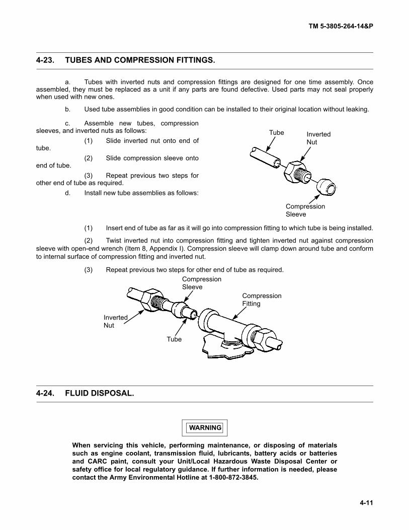
TM 5-3805-264-14&P
4-11
4-23. TUBES AND COMPRESSION FITTINGS.
a. Tubes with inverted nuts and compression fittings are designed for one time assembly. Onceassembled, they must be replaced as a unit if any parts are found defective. Used parts may not seal properlywhen used with new ones.
b. Used tube assemblies in good condition can be installed to their original location without leaking.
c. Assemble new tubes, compressionsleeves, and inverted nuts as follows:
(1) Slide inverted nut onto end oftube.
(2) Slide compression sleeve ontoend of tube.
(3) Repeat previous two steps forother end of tube as required.
d. Install new tube assemblies as follows:
(1) Insert end of tube as far as it will go into compression fitting to which tube is being installed.
(2) Twist inverted nut into compression fitting and tighten inverted nut against compressionsleeve with open-end wrench (Item 8, Appendix I). Compression sleeve will clamp down around tube and conformto internal surface of compression fitting and inverted nut.
(3) Repeat previous two steps for other end of tube as required.
4-24. FLUID DISPOSAL.
WARNING
When servicing this vehicle, performing maintenance, or disposing of materialssuch as engine coolant, transmission fluid, lubricants, battery acids or batteriesand CARC paint, consult your Unit/Local Hazardous Waste Disposal Center orsafety office for local regulatory guidance. If further information is needed, pleasecontact the Army Environmental Hotline at 1-800-872-3845.
Tube InvertedNut
CompressionSleeve
InvertedNut
CompressionSleeve
Tube
CompressionFitting

TM 5-3805-264-14&P
4-12
4-25. SERVICE REPLACEMENT PARTS AND KITS.
Many service replacement parts are available in standard sizes as well as various undersized and/oroversized sizes. Service kits for reconditioning certain parts and service sets, which include all parts necessary tocomplete a procedure, are also available.
4-26. WELDING.
WARNING
Provide adequate ventilation and personal protective equipment before starting anywelding operation. Contact your unit/local Industrial Hygienist or Safety Officer forassistance. Failure to follow this warning may result in injury to personnel.
CAUTION
Before welding, the following components must be disconnected: DDEC ECU, ABSECU, CTIS ECU, Datalogger, and batteries (TM 9-2320-363-20 or TM 9-2320-302-20).If welding on a trailer, it must be uncoupled from dump truck. Failure to follow thiscaution may damage electronic components.
Refer to TM 9-237, Operator's Manual for Welding Theory and Application, for instructions on weldingcomponents.
4-27. ELECTRICAL REPAIR.
a. General. Specific electrical system maintenance tasks are covered in Chapter 4, Section VI of thismanual.
b. Wiring Harness and Cable Repair. Wiring harness and cable repair for the dump truck body isthe same as for the dump truck chassis. Refer to instructions in Chapter 3 of TM 9-2320-363-20 or TM 9-2320-302-20.

TM 5-3805-264-14&P
4-13
Section IV. UNIT PREVENTIVE MAINTENANCE CHECKSAND SERVICES (PMCS)
Paragraph PageNumber Paragraph Title Number
4-28. General . . . . . . . . . . . . . . . . . . . . . . . . . . . . . . . . . . . . . . . . . . . . . . . . . . . . . . . . . . . . . . . . . 4-134-29. Explanation of Table Entries . . . . . . . . . . . . . . . . . . . . . . . . . . . . . . . . . . . . . . . . . . . . . . . . . 4-134-30. General Lubrication Procedures. . . . . . . . . . . . . . . . . . . . . . . . . . . . . . . . . . . . . . . . . . . . . . 4-144-31. General PMCS Procedures . . . . . . . . . . . . . . . . . . . . . . . . . . . . . . . . . . . . . . . . . . . . . . . . . 4-154-32. PMCS Initial Setup . . . . . . . . . . . . . . . . . . . . . . . . . . . . . . . . . . . . . . . . . . . . . . . . . . . . . . . . 4-164-33. Lubrication Data . . . . . . . . . . . . . . . . . . . . . . . . . . . . . . . . . . . . . . . . . . . . . . . . . . . . . . . . . . 4-17Table 4-1. Lubrication Data . . . . . . . . . . . . . . . . . . . . . . . . . . . . . . . . . . . . . . . . . . . . . . . . . . . . . . . . . . 4-174-34. Mandatory Replacement Parts . . . . . . . . . . . . . . . . . . . . . . . . . . . . . . . . . . . . . . . . . . . . . . . 4-18Table 4-2. Unit Preventive Maintenance Checks and Services (PMCS) for M917A1,
M917A1 w/MCS, M917A2, and M917A2 w/MCS Dump Truck Body . . . . . . . . . . . . . . . 4-19
4-28. GENERAL.
NOTE
Refer to TM 9-2320-363-20 or TM 9-2320-302-20 for Unit PMCS for the dump truckchassis.
To ensure that the dump truck body is ready for operation at all times, it must be lubricated and inspectedon a regular basis so that defects may be found before they result in serious damage, equipment failure, or injury topersonnel. Table 4-1 lists the types, amounts, and temperature ranges of the lubricants required for specified inter-vals. Table 4-2 contains systematic instructions on lubrications, inspections, adjustments, and corrections to beperformed by Unit Maintenance to keep your equipment in good operating condition and ready for its primary mis-sion.
4-29. EXPLANATION OF TABLE ENTRIES.
a. Item Number (Item No.) Column. Numbers in this column are for reference. When completingDA Form 2404 (Equipment Inspection and Maintenance Worksheet), include the item number for the check/serviceindicating a fault. Item numbers also appear in the order you must perform checks and services for the intervallisted.
b. Interval Column. This column tells you when you must perform the procedure in the procedurecolumn.
(1) Semiannual procedures must be done once every six months.
(2) Annual procedures must be done once each year.
c. Location, Item to Check/Service Column. This column identifies the location and the item to bechecked or serviced.

TM 5-3805-264-14&P
4-14
4-29. EXPLANATION OF TABLE ENTRIES (Con’t).
NOTEThe WARNINGs and CAUTIONs appearing in your PMCS table should always beobserved. WARNINGs and CAUTIONs appear before applicable procedures. TheseWARNINGs and CAUTIONs must be observed to prevent serious injury to yourselfand others or to prevent your equipment from being damaged.
d. Procedure Column. This column gives the procedure you must perform to check or service theitem listed in the Item to Check/Service column to know if the equipment is ready or available for its intended mis-sion or for operation. You must perform the procedure at the time stated in the interval column.
e. Not Fully Mission Capable If: Column. Information in this column tells you what fault will keepyour equipment from being capable of performing its primary mission. If you make check and service proceduresthat show faults listed in this column, the equipment is not mission-capable. Follow standard operating proceduresfor maintaining the equipment or reporting equipment failure.
4-30. GENERAL LUBRICATION PROCEDURES.
NOTE
Refer to Appendix J, Lubrication Instructions, for Lubrication Chart, key, localizedviews, and procedural notes.
a. Recommended intervals are based on normal conditions of operation, temperature, and humidity.When operating under extreme conditions, lubricants should always be changed more frequently. When in doubt,notify your supervisor.
b. Keep all lubricants in a closed container and store in a clean, dry place away from extreme heat orcold. Keep container covers clean and do not allow dust, dirt, or other foreign material to mix with lubricants. Keepall lubrication equipment clean and ready for use.
c. Maintain a good record of all lubrication performed and report any problems noted during lubrica-tion. Refer to DA Pam 738-750 for maintenance forms and procedures to record and report any findings.
d. Keep all external parts of equipment not requiring lubrication free of lubricants. Before lubrication,wipe lubrication fittings with a clean rag (Item 16, Appendix F). After lubrication, wipe off excess oil or grease toprevent accumulation of foreign matter.
e. Refer to FM 9-207 for lubrication instructions in cold weather.f. Refer to AR 70-12 for use of standardized lubricants.g. Hydraulic oil filter element will be changed when it is known to be contaminated or clogged.h. Hydraulic oil must be sampled initially at 90 days of operation, as prescribed by DA Pam 738-750.

TM 5-3805-264-14&P
4-15
4-31. GENERAL PMCS PROCEDURES.
a. Always perform PMCS in the same order so it gets to be a habit. Once you've had some practice,you'll spot anything wrong in a hurry. If any deficiency is discovered, perform the appropriate troubleshooting taskin Section V of this chapter. If any component or system is not serviceable, or if the given service does not correctthe deficiency, notify your supervisor.
b. Before performing preventive maintenance, read all the checks required for the applicable intervaland prepare all tools needed to make all checks. Have several clean rags (Item 16, Appendix F) handy. PerformALL inspections at the applicable interval.
WARNING
Dry cleaning solvent MIL-PRF-680 Type III is an environmentally compliant and lowtoxic material. However, it may be irritating to the eyes and skin. The use of protec-tive gloves and goggles is suggested. Use in well-ventilated area. Keep away fromopen flame and other sources of ignition.
(1) Keep It Clean. Dirt, grease, oil, and debris get in the way and may cover up a serious prob-lem. Clean as you work and as needed. Use dry cleaning solvent (Item 5, Appendix F) on all metal surfaces. Usedishwashing compound (Item 6, Appendix F) and water when you clean rubber, plastic, and painted surfaces.
(2) Deterioration, Rust, and Corrosion.
(a) Be alert for deterioration of plastic and rubber materials. Report it to your supervisor.
(b) Check metal parts for rust and corrosion. If any bare metal or corrosion exists, cleanand apply a light coat of lubricating oil (Item 15, Appendix F). Report it to your supervisor.
(3) Bolts, Nuts, and Screws. Check bolts, nuts, and screws for obvious looseness, missing,bent, or broken condition. You can't try them all with a tool, but look for chipped paint, bare metal, or rust aroundbolt heads. If you find one you think is loose, tighten it.
(4) Welds. Look for loose or chipped paint, rust, or gaps where parts are welded together. Ifyou find a bad weld, report it to your supervisor.
(5) Electric Wires and Connectors. Look for cracked or broken insulation, bare wires, andloose or broken connectors. Tighten loose connectors and ensure that the wires are in good condition.
(6) Hydraulic Hoses and Lines. Look for wear, damage, and signs of leaks. Ensure thatclamps and fittings are tight. Wet spots indicate leaks, but a stain around a fitting or connector can also mean aleak. If a leak comes from a loose fitting or connector, tighten it. If something is broken or worn out, correct it ifauthorized by the Maintenance Allocation Chart (Appendix B). If not authorized, notify your supervisor.
(7) Fluid Leakage. It is necessary for you to know how fluid leakage affects the status of yourdump truck. The following are definitions of the types/classes of leakage you need to know to be able to determinethe status of your equipment. Learn and be familiar with them, and remember-- when in doubt, notify your supervi-sor.

TM 5-3805-264-14&P
4-16
4-31. GENERAL PMCS PROCEDURES (Con’t).
Leakage Definitions for Unit PMCS
Class I Leakage indicated by wetness or discoloration, but not great enough to formdrops.
Class II Leakage great enough to form drops, but not enough to cause drops to dripfrom the item being checked/inspected.
Class III Leakage great enough to form drops that fall from the item being checked/inspected.
CAUTION
Operation is allowable with Class I and Class II leakage. WHEN IN DOUBT, NOTIFY YOUR SUPERVISOR. When operating with Class I or Class II leaks, check fluid lev-els more frequently. Class III leaks must be reported immediately to your supervi-
sor. Failure to do this will result in damage to vehicle and/or components.
4-32. PMCS INITIAL SETUP.
a. General.
(1) This paragraph lists tools, materials, and personnel required for PMCS and lubrication.
(2) Mandatory replacement parts for PMCS and lubrication are listed in paragraph 4-34.
b. Tools.
(1) Drain pan (Item 4, Appendix I).
(2) General mechanic’s tool kit (Item 8, Appendix I).
c. Materials.
(1) Corrosion preventive (Item 8, Appendix F)
(2) Dishwashing compound (Item 6, Appendix F)
(3) Detergent (Item 9, Appendix F)
(4) Lubricating oil, OEA (Item 13, Appendix F)
(5) Lubricating oil, OE/HDO 10 (Item 14, Appendix F)
(6) Lubricating oil, OE/HDO 30 (Item 15, Appendix F)
(7) Rags (Item 16, Appendix F)
(8) Cleaning solvent (Item 5, Appendix F)
d. Personnel.
(1) Driver/Operator
(2) Unit Maintenance Mechanic
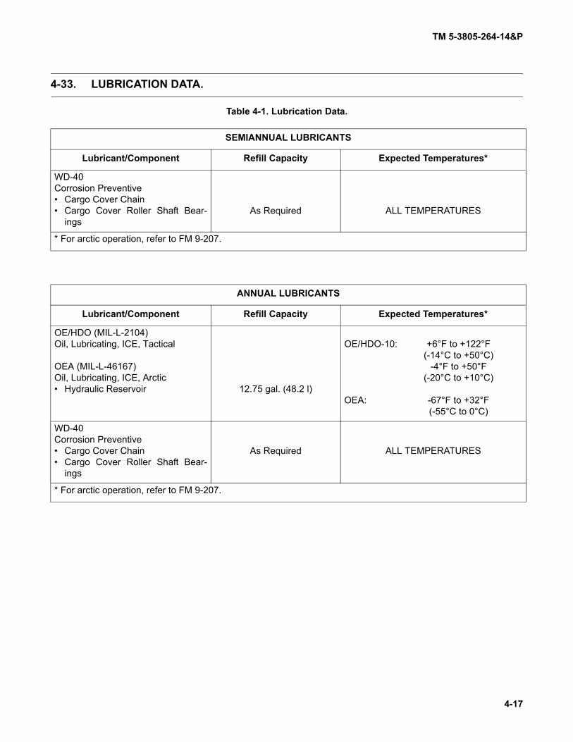
TM 5-3805-264-14&P
4-17
4-33. LUBRICATION DATA.
Table 4-1. Lubrication Data.
SEMIANNUAL LUBRICANTS
Lubricant/Component Refill Capacity Expected Temperatures*
WD-40Corrosion Preventive• Cargo Cover Chain• Cargo Cover Roller Shaft Bear-
ingsAs Required ALL TEMPERATURES
* For arctic operation, refer to FM 9-207.
ANNUAL LUBRICANTS
Lubricant/Component Refill Capacity Expected Temperatures*
OE/HDO (MIL-L-2104)Oil, Lubricating, ICE, Tactical
OEA (MIL-L-46167)Oil, Lubricating, ICE, Arctic• Hydraulic Reservoir 12.75 gal. (48.2 l)
OE/HDO-10: +6°F to +122°F(-14°C to +50°C)
-4°F to +50°F(-20°C to +10°C)
OEA: -67°F to +32°F(-55°C to 0°C)
WD-40Corrosion Preventive• Cargo Cover Chain• Cargo Cover Roller Shaft Bear-
ings
As Required ALL TEMPERATURES
* For arctic operation, refer to FM 9-207.

TM 5-3805-264-14&P
4-18
4-34. MANDATORY REPLACEMENT PARTS.
NOTE
Refer to Appendix C for more information on mandatory replacement parts.
ANNUAL
Nomenclature Qty (CAGEC) P/N NSNFilter element, hydraulic oil 1 (5X050) 403366 4330-01-446-3337Preformed packing, filter
housing cover 1 (60827) 251-70-BN 5330-01-447-4034

TM 5-3805-264-14&P
4-19
Table 4-2. Unit Preventive Maintenance Checks and Services (PMCS) for M917A1,M917A1 w/MCS, M917A2, and M917A2 w/MCS Dump Truck Body.
Item No. Interval
Location
ProcedureNot Fully Mission
Capable If:
Item ToCheck/Service
WARNING
Unless otherwise specified, per-form all lubrication and preventivemaintenance checks with dumptruck on level ground, transmissionin N (Neutral), parking brake set,and engine off. Failure to followthis warning may result in person-nel injury.
NOTE• Perform all Operator PMCS,
(Chapter 2, Section II) as appro-priate, while performing Item No.1-4 checks. Drive at least 5 mi (8km) to give enough time todetect malfunctions.
• Dump truck’s chassis air systemactivates both models’ tailgatelocking mechanism and inter-faces with MCS air system on theM917A1 w/MCS and M917A2 w/MCS to operate the MCS tailgate.
1 Semi- annual
Tailgate Operation
a. Start engine and fully pressurizevehicle air systems (TM 9-2320-363-10 or TM 9-2320-302-10). Lis-ten for air leaks.
a. Air leaks are present.
b. Operate tailgate release controlvalve lever in cab (paragraph 2-1).Check that tailgate unlocks andlocks.

TM 5-3805-264-14&P
4-20
Table 4-2. Unit Preventive Maintenance Checks and Services (PMCS) for M917A1,M917A1 w/MCS, M917A2, and M917A2 w/MCS Dump Truck Body (Con’t).
Item No. Interval
Location
ProcedureNot Fully Mission
Capable If:
Item ToCheck/Service
2 Semi-annual
MCS Tail-gateOperation (M917A1w/MCS andM917A2w/MCS)
Check operation of MCS gates (para-graph 2-12). Listen for air leaks.
Air leaks are present.
3 Semi-annual
Hydraulic System Operation
Raise and lower dump body andcheck for smooth operation (para-graph 2-10). Be alert for hydraulic fluidleaks.
Class III hydraulic fluid leaks arepresent.
WARNING
Observe the following safety regu-lations when operating cargocover:
a. Never operate system underobstructions, such as treesand power lines.
b. Ensure that all personnel areclear of rear of dump bodyand the immediate area ofthe cover.
c. Ensure that chain cover is inplace.
d. Keep all clothing away frommoving parts.
e. DO NOT cover load withcrank handle installed.
Failure to follow this warning mayresult in death or injury to person-nel.

TM 5-3805-264-14&P
4-21
Table 4-2. Unit Preventive Maintenance Checks and Services (PMCS) for M917A1,M917A1 w/MCS, M917A2, and M917A2 w/MCS Dump Truck Body (Con’t).
Item No. Interval
Location
ProcedureNot Fully Mission
Capable If:
Item ToCheck/Service
4 Semi-annual
Cargo Cover
a. Operate cargo cover and check forsmooth operation (paragraph 2-14).
b. Remove chain cover (paragraph 4-66). Inspect chain for dirt, corro-sion or other damage. Check forproper chain adjustment. Replacechain if damaged (paragraph 4-66).
c. Lubricate chain sparingly with cor-rosion preventive (Item 8, Appen-dix F).
d. Lubricate roller shaft bearings (1)at left and right side roll-up barmounting brackets (2). Apply cor-rosion preventive (Item 8, Appen-dix F) sparingly.
e. Install chain cover (paragraph 4-66).
5 Semi-annual
Dump Body a. With dump body down, inspectdump body and tailgate for cracks,breaks, bends, weld breaks, wear,and missing or loose bolts.
b. Inspect for corrosion in accor-dance with TM 43-0213.
21

TM 5-3805-264-14&P
4-22
Table 4-2. Unit Preventive Maintenance Checks and Services (PMCS) for M917A1,M917A1 w/MCS, M917A2, and M917A2 w/MCS Dump Truck Body (Con’t).
Item No. Interval
Location
ProcedureNot Fully Mission
Capable If:
Item ToCheck/Service
6 Semi-annual
Body Props Inspect body props for binding ordamage. Replace if damaged (para-graph 4-61).
WARNING
NEVER work under a raised dumpbody unless it is secured in theraised position with body propsand dump body is EMPTY. Failureto follow this warning may result indeath or injury to personnel.
7 Semi-annual
Hydraulic Reservoir, Fill Cap Vent
a. Raise dump body and support withbody props (paragraph 2-15).
WARNING
To prevent burns, use cautionwhen removing fill cap of hydraulicreservoir when hydraulic fluid ishot. Avoid contact with hot hydrau-lic oil. Failure to follow this warningmay result in injury to personnel.b. Remove fill cap from reservoir.
Clean fill cap vent in accordancewith Chapter 4, Section III, Gen-eral Maintenance Instructions.Install fill cap.
WARNING
DO NOT disconnect hydraulic lineswhile engine is running. Enginemust be shut down and dump bodyfully lowered or supported on bodyprops before lines are discon-nected. Escaping hydraulic fluidunder pressure can penetrate theskin, causing serious injury to per-sonnel.c. Inspect all hydraulic lines, fittings,
and components for signs of leaks.Tighten any connections that areloose. Ensure that hydraulic linesare supported. Replace any dam-aged component.

TM 5-3805-264-14&P
4-23
Table 4-2. Unit Preventive Maintenance Checks and Services (PMCS) for M917A1,M917A1 w/MCS, M917A2, and M917A2 w/MCS Dump Truck Body (Con’t).
Item No. Interval
Location
ProcedureNot Fully Mission
Capable If:
Item ToCheck/Service
WARNING
NEVER work under a raised dumpbody unless it is secured in theraised position with body propsand dump body is EMPTY. Failureto follow this warning may result indeath or injury to personnel.
8 Semi-annual
Stabilizer Inspect stabilizer for loose mountingor damage. If damaged, notify DirectSupport Maintenance.
WARNING
NEVER work under a raised dumpbody unless it is secured in theraised position with body propsand dump body is EMPTY. Failureto follow this warning may result indeath or injury to personnel.
9 Semi-annual
Tailgate Release Air Cylinder Lines
With vehicle air system pressurized,check air lines, fittings, and tailgaterelease air cylinder under dump bodyfor loose mounting, leaks or damage.A solution of detergent (Item 9,Appendix F) and water applied to linesand fittings will help locate leaks.
WARNING
NEVER work under a raised dumpbody unless it is secured in theraised position with body propsand dump body is EMPTY. Failureto follow this warning may result indeath or injury to personnel.
10 Semi-annual
Tailgate Locking Linkage
Inspect tailgate locking linkage forbreaks, bends, cracks, corrosion, andloose mounting.

TM 5-3805-264-14&P
4-24
Table 4-2. Unit Preventive Maintenance Checks and Services (PMCS) for M917A1,M917A1 w/MCS, M917A2, and M917A2 w/MCS Dump Truck Body (Con’t).
Item No. Interval
Location
ProcedureNot Fully Mission
Capable If:
Item ToCheck/Service
WARNING
NEVER work under a raised dumpbody unless it is secured in theraised position with body props anddump body is EMPTY. Failure to fol-low this warning may result indeath or injury to personnel.
11 Semi-annual
Frame and Crossmem-bers
a. Inspect dump body frame andcrossmembers for cracks, breaks,bends, weld breaks, wear, andmissing or loose bolts and rivets.
b. Inspect for corrosion in accordancewith TM 43-0213.
c. Remove body props and lowerdump body (paragraph 2-15).
12 Annual Decals and Stencils
Check all decals and stencils toensure legibility.
WARNING
To prevent burns, use cautionwhen removing fill cap of hydraulicreservoir when hydraulic fluid ishot. Avoid contact with hot hydrau-lic oil. Use extreme care whendraining hydraulic oil. Failure tofollow this warning may result ininjury to personnel.
13 10,000 Miles or Annual
Hydraulic Reservoir
a. With dump body down and engineoff, remove magnetic drain plugfrom underside of reservoir (7).Drain hydraulic oil into a suitablecontainer.

TM 5-3805-264-14&P
4-25
Table 4-2. Unit Preventive Maintenance Checks and Services (PMCS) for M917A1,M917A1 w/MCS, M917A2, and M917A2 w/MCS Dump Truck Body (Con’t).
Item No. Interval
Location
ProcedureNot Fully Mission
Capable If:
Item ToCheck/Service
13 (Con’t)
10,000 Miles or Annual
Hydraulic Reservoir
b. Remove fill cap (5). Removestrainer from reservoir (7) (para-graph 4-75). Clean strainer andreinstall.
c. Replace hydraulic oil filter element(paragraph 4-76).
d. Clean drain plug and reinstall.
NOTEHydraulic reservoir capacity is 12.75gal. (48.2 l). DO NOT overfill.
e. Fill reservoir (7) with lubricating oil(Item 13 or 14, Appendix F) untillevel of fluid in sight tube (4) is atFULL mark as indicated on oil leveldecal (6). Install fill cap (5).
6
74
5

TM 5-3805-264-14&P
4-26
Section V. UNIT TROUBLESHOOTING PROCEDURES
Paragraph PageNumber Paragraph Title Number
4-35. General . . . . . . . . . . . . . . . . . . . . . . . . . . . . . . . . . . . . . . . . . . . . . . . . . . . . . . . . . . . . . . . . . 4-264-36. Explanation of Columns . . . . . . . . . . . . . . . . . . . . . . . . . . . . . . . . . . . . . . . . . . . . . . . . . . . . 4-264-37. Troubleshooting Symptom Index . . . . . . . . . . . . . . . . . . . . . . . . . . . . . . . . . . . . . . . . . . . . . 4-27Table 4-3. Unit Troubleshooting. . . . . . . . . . . . . . . . . . . . . . . . . . . . . . . . . . . . . . . . . . . . . . . . . . . . . . . 4-28
4-35. GENERAL.
a. This section provides information for identifying and correcting malfunctions that you may findwhile operating and maintaining the dump truck body.
b. The Troubleshooting Symptom Index (paragraph 4-37) lists common malfunctions which mayoccur and refers you to the proper page in Table 4-3 for a troubleshooting procedure.
c. If you are unaware of the location of an item mentioned in troubleshooting, refer to paragraphs 1-11, 2-1 or 2-2.
d. Before performing troubleshooting, read and follow all safety instructions found in the warningsummary at the front of this manual.
e. This section cannot list all malfunctions that may occur, nor all tests or inspections and correctiveactions. If a malfunction is not listed, or is not corrected by the listed corrective actions, notify your supervisor.
f. When troubleshooting a malfunction:
(1) Locate the symptom or symptoms in paragraph 4-37 that best describes the malfunction. Ifthe appropriate symptom is not listed, notify your supervisor.
(2) Turn to the page in Table 4-3 where the troubleshooting procedures for the malfunction inquestion are described. Headings at the top of each page show how each troubleshooting procedure is organized:Malfunction, Test or Inspection (in step number order), and Corrective Action.
(3) Perform each step in the order listed until the malfunction is corrected and the item beinginspected is operational. DO NOT perform any maintenance task unless the troubleshooting procedure tells you todo so.
4-36. EXPLANATION OF COLUMNS.
The columns in Table 4-3 are defined as follows:
(1) MALFUNCTION. A visual or operational indication that something is wrong with the equip-ment.
(2) TEST OR INSPECTION. A procedure to isolate the problem in a system or component.
(3) CORRECTIVE ACTION. A procedure to correct the problem.

TM 5-3805-264-14&P
4-27
4-37. TROUBLESHOOTING SYMPTOM INDEX.
Troubleshooting Procedure
Page DUMP BODY TROUBLESHOOTING
HYDRAULIC SYSTEM
Dump Body Lowers With Hydraulic Control Lever in the Neutral Positionand PTO Disengaged............................................................................................................... 4-31
Dump Body Lowers With Hydraulic Control Lever in the NeutralPosition and PTO Engaged...................................................................................................... 4-31
Dump Body Raises and Lowers Sluggishly ................................................................................. 4-31Dump Body Raises With Hydraulic Control Lever in the Neutral Position and PTO Engaged .... 4-31Dump Body Will Not Raise and/or Lower..................................................................................... 4-30
MCS (M917A1 w/MCS and M917A2 w/MCS)
MCS Gate Will Not Operate......................................................................................................... 4-28MCS Gate Will Not Operate With Driver’s Controls..................................................................... 4-28MCS Gate Will Not Operate With Remote Control ...................................................................... 4-29MCS Gates Open or Close When Remote Control Is Connected ............................................... 4-29One or More MCS Gates Will Not Open or Close Properly ......................................................... 4-30
TAILGATE
Tailgate Assembly Lock Will Not Release.................................................................................... 4-30

TM 5-3805-264-14&P
4-28
Table 4-3. Unit Troubleshooting.
MALFUNCTIONTEST OR INSPECTION
CORRECTIVE ACTION
MCS (M917A1 W/MCS AND M917A2 W/MCS)
1. MCS GATE WILL NOT OPERATE.
Step 1. Check for air leaks throughout vehicle (chassis) air system.
Tighten or replace leaking or damaged air system components (TM 9-2320-363-20 or TM9-2320-302-20).
Step 2. Check for leaking air hoses, fittings, or valves on MCS tailgate.
Tighten or replace leaking or damaged air hoses and fittings (paragraph 4-59).
Step 3. Check for leaking or damaged MCS air reservoir.
Replace MCS air reservoir (paragraph 4-55).
Step 4. Check for leaking or damaged MCS air cylinder.
Replace or repair MCS air cylinder (paragraph 4-56, 4-57, or 4-58).
2. MCS GATE WILL NOT OPERATE WITH DRIVER’S CONTROLS.
Step 1. Check for air leaks throughout vehicle (chassis) air system.
Tighten or replace leaking or damaged air system components (TM 9-2320-363-20 or TM9-2320-302-20).
Step 2. Check MCS tailgate for leaking or damaged air system components.
Tighten or replace leaking or damaged components (paragraphs 4-55 thru 4-59).
NOTEFor assistance in troubleshooting an MCS electrical malfunction, refer to wiring diagrams(paragraph 4-49).
Step 3. Check MCS fuse for continuity.
Replace damaged fuse (TM 9-2320-363-20 or TM 9-2320-302-20).
Step 4. Check driver’s MCS control unit switches for voltage and continuity.
Replace damaged switches (paragraph 4-42).
Step 5. Check truck-to-MCS tailgate wiring harness for voltage and continuity.
Repair or replace damaged truck-to-MCS tailgate wiring harness (paragraph 4-47).
Step 6. Check MCS tailgate wiring harness and air cylinder solenoids for voltage and continuity.
Repair or replace damaged MCS tailgate wiring harness (paragraph 4-48).
Replace damaged MCS air cylinder solenoids (paragraph 4-57).

TM 5-3805-264-14&P
4-29
Table 4-3. Unit Troubleshooting (Con’t).
MALFUNCTIONTEST OR INSPECTION
CORRECTIVE ACTION
3. MCS GATE WILL NOT OPERATE WITH REMOTE CONTROL.
Step 1. Check for air leaks throughout vehicle (chassis) air system.
Tighten or replace leaking or damaged air system components (TM 9-2320-363-20 or TM9-2320-302-20).
Step 2. Check MCS tailgate for leaking or damaged air system components.
Tighten or replace leaking or damaged components (paragraphs 4-55 thru 4-59).
NOTE
For assistance in troubleshooting an MCS electrical malfunction, refer to wiring dia-grams (paragraph 4-49).
Step 3. Check MCS fuse for continuity.
Replace damaged fuse (TM 9-2320-363-20 or TM 9-2320-302-20).
Step 4. Check MCS remote control switches for voltage and continuity.
Replace damaged switches (paragraph 4-43).
Replace damaged remote control.
Step 5. Check MCS remote control cable for voltage and continuity.
Replace damaged remote control cable (paragraph 4-43).
Step 6. Check truck-to-MCS tailgate wiring harness for voltage and continuity.
Repair or replace damaged truck-to-MCS tailgate wiring harness (paragraph 4-47).
Step 7. Check MCS tailgate wiring harness and MCS air cylinder solenoids for voltage and continu-ity.
Repair or replace damaged MCS tailgate wiring harness (paragraph 4-48).
Replace damaged MCS air cylinder solenoids (paragraph 4-57).
4. MCS GATES OPEN OR CLOSE WHEN REMOTE CONTROL IS CONNECTED.
NOTE
For assistance in troubleshooting an MCS electrical malfunction, refer to wiring diagrams(paragraph 4-49).
Step 1. Check MCS remote control switches for voltage and continuity.
Replace damaged switches (paragraph 4-43).
Replace damaged remote control.

TM 5-3805-264-14&P
4-30
Table 4-3. Unit Troubleshooting (Con’t).
MALFUNCTIONTEST OR INSPECTION
CORRECTIVE ACTION
Step 2. Check MCS remote control cable for voltage and continuity.
Replace damaged remote control cable (paragraph 4-43).
Step 3. Check MCS tailgate wiring harness and MCS air cylinder solenoids for voltage and continu-ity.
Repair or replace damaged MCS tailgate wiring harness (paragraph 4-48).
Replace damaged MCS air cylinder solenoids (paragraph 4-57).
5. ONE OR MORE MCS GATES WILL NOT OPEN OR CLOSE PROPERLY.
Step 1. Check MCS tailgate for leaking or damaged air system components.
Tighten or replace leaking or damaged components (paragraphs 4-55 thru 4-59).
Step 2. Check MCS tailgate for damaged gates.
Replace damaged gate (paragraph 4-54).
Step 3. Check MCS tailgate for damaged gate adjustment tubes and locking pins.
Replace damaged adjustment tube (paragraph 4-60).
TAILGATE6. TAILGATE ASSEMBLY LOCK WILL NOT RELEASE.
Step 1. Check for air leaks throughout vehicle (chassis) air system.
Tighten or replace leaking or damaged air system components (TM 9-2320-363-20 or TM9-2320-302-20).
Step 2. Check for damaged or leaking tailgate release air cylinder.
Repair or replace tailgate release air cylinder (paragraph 4-51 or 4-58).
Step 3. Check for damaged tailgate locking linkage.
Notify Direct Support.
HYDRAULIC SYSTEM
7. DUMP BODY WILL NOT RAISE AND/OR LOWER.
Step 1. Check if Power Take-Off (PTO) is operating properly.
Check PTO operation (TM 9-2320-363-10 or TM 9-2320-302-10).
Step 2. Check for damaged hydraulic hoses.
Replace damaged hydraulic hoses (paragraph 4-74).
Step 3. Check for damaged or out of adjustment hydraulic control lever cable.
Adjust hydraulic control lever cable (paragraph 4-73).
Replace damaged hydraulic control lever cable (paragraph 4-73).

TM 5-3805-264-14&P
4-31
Table 4-3. Unit Troubleshooting (Con’t).
MALFUNCTIONTEST OR INSPECTION
CORRECTIVE ACTION
Step 4. Dump body still will not operate properly.
Notify Direct Support.
8. DUMP BODY RAISES WITH HYDRAULIC CONTROL LEVER IN THE NEUTRAL POSITION AND PTOENGAGED.
Step 1. Check for damaged or out of adjustment hydraulic control lever cable.
Adjust hydraulic control lever cable (paragraph 4-73).
Replace damaged hydraulic control lever cable (paragraph 4-73).
Step 2. Dump body still will not operate properly.
Notify Direct Support.
9. DUMP BODY LOWERS WITH HYDRAULIC CONTROL LEVER IN THE NEUTRAL POSITION AND PTOENGAGED.
Step 1. Check for damaged or out of adjustment hydraulic control lever cable.
Adjust hydraulic control lever cable (paragraph 4-73).
Replace damaged hydraulic control lever cable (paragraph 4-73).
Step 2. Dump body still will not operate properly.
Notify Direct Support.
10. DUMP BODY LOWERS WITH HYDRAULIC CONTROL LEVER IN THE NEUTRAL POSITION AND PTODISENGAGED.
Step 1. Check for damaged or out of adjustment hydraulic control lever cable.
Adjust hydraulic control lever cable (paragraph 4-73).
Replace damaged hydraulic control lever cable (paragraph 4-73).
Step 2. Dump body still will not operate properly.
Notify Direct Support.
11. DUMP BODY RAISES AND LOWERS SLUGGISHLY.
Step 1. Check hydraulic filter service indicator gage.
Service hydraulic oil filter (paragraph 4-77).
Step 2. Check engine idle speed (TM 9-2320-363-20 or TM 9-2320-302-20).
Step 3. Check for damaged hydraulic hoses.
Replace damaged hydraulic hoses (paragraph 4-74).
Step 4. Check for binding bearings at pivot points of dump body, hydraulic cylinder, and stabilizer.
Notify Direct Support.

TM 5-3805-264-14&P
4-32
Section VI. ELECTRICAL SYSTEM MAINTENANCE
Paragraph PageNumber Paragraph Title Number
4-38. Body Up Switch Replacement . . . . . . . . . . . . . . . . . . . . . . . . . . . . . . . . . . . . . . . . . . . . . . . 4-324-39. Transport Lock Switch Replacement . . . . . . . . . . . . . . . . . . . . . . . . . . . . . . . . . . . . . . . . . . 4-344-40. Taillight Replacement . . . . . . . . . . . . . . . . . . . . . . . . . . . . . . . . . . . . . . . . . . . . . . . . . . . . . . 4-364-41. Marker Clearance Light Replacement . . . . . . . . . . . . . . . . . . . . . . . . . . . . . . . . . . . . . . . . . 4-374-42. MCS Control Unit Maintenance (M917A1 w/MCS and M917A2 w/MCS). . . . . . . . . . . . . . . 4-384-43. MCS Remote Control Repair (M917A1w/MCS and M917A2 w/MCS) . . . . . . . . . . . . . . . . . 4-424-44. Body Up and Transport Lock Switches Wiring Harness Maintenance . . . . . . . . . . . . . . . . . 4-474-45. Beacon Warning Light Wiring Harness Maintenance . . . . . . . . . . . . . . . . . . . . . . . . . . . . . . 4-494-46. Lights Wiring Harness Maintenance. . . . . . . . . . . . . . . . . . . . . . . . . . . . . . . . . . . . . . . . . . . 4-524-47. Truck-to-MCS Tailgate Wiring Harness Maintenance (M917A1 w/MCS and
M917A2 w/MCS) . . . . . . . . . . . . . . . . . . . . . . . . . . . . . . . . . . . . . . . . . . . . . . . . . . . . . . . . 4-544-48. MCS Tailgate Wiring Harness Maintenance (M917A1 w/MCS and M917A2 w/MCS) . . . . . 4-584-49. Wiring Diagrams . . . . . . . . . . . . . . . . . . . . . . . . . . . . . . . . . . . . . . . . . . . . . . . . . . . . . . . . . . 4-62
4-38. BODY UP SWITCH REPLACEMENT.
This task covers:
a. Removal b. Installation
Initial Setup:
Equipment Conditions:• Dump body raised and supported on body props
(paragraph 2-15).• Batteries disconnected (TM 9-2320-363-20)
(M917A1 and M917A1 w/MCS).• Master battery switch OFF (TM 9-2320-302-10)
(M917A2 and M917A2 w/MCS)
Tools/Test Equipment:• General mechanic’s tool kit (Item 8, Appendix I)
Materials/Parts:• Marker tags (Item 20, Appendix F)
General Safety Instructions:• NEVER work under a raised dump body unless it
is secured in the raised position with body propsand dump body is EMPTY.
WARNING
NEVER work under a raised dump body unless it is secured in the raised positionwith body props and dump body is EMPTY. Failure to follow this warning may resultin death or injury to personnel.

TM 5-3805-264-14&P
4-33
4-38. BODY UP SWITCH REPLACEMENT (Con’t).
NOTE
Wires should be tagged before disconnecting (paragraph 4-17).
1. Disconnect two wiring harness leads (2) from body up switch (1).
NOTE
To ensure proper installation, note switch lever position.
2. Remove two screws (4) and body up switch (1) from cylinder support frame (3).
1. Install body up switch (1) on cylinder support frame (3) with two screws (4).
2. Connect two wiring harness leads (2) to body up switch (1).
FOLLOW-ON TASKS:
• Connect batteries (TM 9-2320-363-20) (M917A1 and M917A1 w/MCS).• Remove body props and lower dump body (paragraph 2-15).• Check operation of body up switch (paragraph 2-1).
a. REMOVAL
34
1
2
b. INSTALLATION

TM 5-3805-264-14&P
4-34
4-39. TRANSPORT LOCK SWITCH REPLACEMENT.
This task covers:a. Removal b. Installation
Initial Setup:Equipment Conditions:
• Dump body raised and supported on body props(paragraph 2-15).
• Batteries disconnected (TM 9-2320-363-20)(M917A1 and M917A1 w/MCS).
• Master battery switch OFF (TM 9-2320-302-10)(M917A2 and M917A2 w/MCS)
Tools/Test Equipment:• General mechanic’s tool kit (Item 8, Appendix I)
Materials/Parts:• Tie wraps (Item 19, Appendix F)
General Safety Instructions:• NEVER work under a raised dump body unless it
is secured in the raised position with body propsand dump body is EMPTY.
WARNING
NEVER work under a raised dump body unless it is secured in the raised positionwith body props and dump body is EMPTY. Failure to follow this warning may resultin death or injury to personnel.
NOTENote location of tie wraps prior to removal to aid in installation.
1. Disconnect transport lock switch connector (2) from wiring harness connector (1).2. Remove button (7), nut (6), and transport lock switch (3) from chassis mount (5).
a. REMOVAL
1 2 35
6
7

TM 5-3805-264-14&P
4-35
4-39. TRANSPORT LOCK SWITCH REPLACEMENT (Con’t).
NOTETo ensure proper installation, note position of jamnut on transport lock switch.
3. Remove jamnut (4) from transport lock switch (3).
1. Install jamnut (4) on transport lock switch (3) in same position as noted during removal.2. Position transport lock switch (3) through hole in chassis mount (5) and install nut (6) and button (7).3. Connect transport lock switch connector (2) to wiring harness connector (1).4. Install new tie wraps, as required.
FOLLOW-ON TASKS:• Connect batteries (TM 9-2320-363-20) (M917A1 and M917A1 w/MCS).• Remove body props and lower dump body (paragraph 2-15).• Check operation of transport lock switch (paragraph 2-1).
b. INSTALLATION
1 2 3 4
5
6
7

TM 5-3805-264-14&P
4-36
4-40. TAILLIGHT REPLACEMENT.
This task covers:
a. Removal b. Installation
Initial Setup:
Equipment Conditions:• Batteries disconnected (TM 9-2320-363-20)
(M917A1 and M917A1 w/MCS).• Master battery switch OFF (TM 9-2320-302-10)
(M917A2 and M917A2 w/MCS)
Tools/Test Equipment:• General mechanic’s tool kit (Item 8, Appendix I)
1. Remove taillight (4) from grommet (3).
2. Disconnect lights wiring harness connector (2) from taillight (4). Remove taillight.
3. Remove grommet (3) from dump body (1).
1. Install grommet (3) in dump body (1).
2. Connect lights wiring harness connector (2) to taillight (4).
3. Install taillight (4) in grommet (3).
FOLLOW-ON TASKS:• Connect batteries (TM 9-2320-363-20) (M917A1 and M917A1 w/MCS).• Check operation of taillight (TM 9-2320-363-10 or TM 9-2320-302-10).
a. REMOVAL
12 3 4
b. INSTALLATION

TM 5-3805-264-14&P
4-37
4-41. MARKER CLEARANCE LIGHT REPLACEMENT.
This task covers:
a. Removal b. Installation
Initial Setup:
Equipment Conditions:• Batteries disconnected (TM 9-2320-363-20)
(M917A1 and M917A1 w/MCS).• Master battery switch OFF (TM 9-2320-302-10)
(M917A2 and M917A2 w/MCS)
Tools/Test Equipment:• General mechanic’s tool kit (Item 8, Appendix I)
NOTEThere is a marker clearance light on each side of dump body and a cluster of threemarker clearance lights on bracket at rear hinge. Replacement of a dump bodymarker clearance light is shown.
1. Remove marker clearance light (1) from grommet (2).2. Disconnect lights wiring harness connector (3) from back of marker clearance light (1). Remove marker
clearance light.3. Remove grommet (2) from dump body (4).
1. Install grommet (2) in dump body (4).2. Connect lights wiring harness connector (3) to back of marker clearance light (1).3. Install marker clearance light (1) in grommet (2).FOLLOW-ON TASKS:
• Connect batteries (TM 9-2320-363-20) (M917A1 and M917A1 w/MCS).• Check operation of marker clearance lights (TM 9-2320-363-10 or TM 9-2320-302-
10).
a. REMOVAL
1 2 3 4
b. INSTALLATION

TM 5-3805-264-14&P
4-38
4-42. MCS CONTROL UNIT MAINTENANCE (M917A1 W/MCS and M917A2 W/MCS).
This task covers:
M917A1 W/MCSa. Removalb. Disassemblyc. Cleaning and Inspection
d. Assemblye. InstallationM917A2 W/MCSf. MCS Switch Replacement
Initial Setup:
Equipment Conditions:• Batteries disconnected (TM 9-2320-363-20)
(M917A1 and M917A1 w/MCS).• Master battery switch OFF (TM 9-2320-302-10)
(M917A2 and M917A2 w/MCS)
Tools/Test Equipment:
• General mechanic’s tool kit (Item 8, Appendix I)
Materials/Parts:
• Marker tags (Item 20, Appendix F)
M917A1 W/MCS
NOTEWires should be tagged before disconnecting (paragraph 4-17).
1. Remove four screws (7), washers (8), and MCS control unit (3) from shift tower (1).2. Disconnect indicator light connector (5) from wiring harness connector (6).3. Disconnect four wiring harness leads (4) from toggle switches (2). Remove MCS control unit (3).
a. REMOVAL
1
2
3
456
7
8

TM 5-3805-264-14&P
4-39
4-42. MCS CONTROL UNIT MAINTENANCE (M917A1 W/MCS andM917A2W/MCS) (Con’t).
1. Remove indicator light (9) from bracket (11).2. Remove four nuts (10) and toggle switches (2)
from bracket (11).
Clean and inspect components in accordance with Chapter 4, Section III, General Maintenance Instruc-tions.
1. Install four toggle switches (2) to bracket (11) with four nuts (10).
2. Install indicator light (9) to bracket (11).
1. Connect four wiring harness leads (4) to toggle switches (2).
2. Connect wiring harness connector (6) to indicator light connector (5).
3. Install MCS control unit (3) on shift tower (1) with four washers (8) and screws (7).
b. DISASSEMBLY
10
911
2
c. CLEANING AND INSPECTION
d. ASSEMBLY
e. INSTALLATION

TM 5-3805-264-14&P
4-40
4-42. MCS CONTROL UNIT MAINTENANCE (M917A1 W/MCS andM917A2W/MCS) (Con’t).
M917A2 W/MCS
1. Drain air system (TM 9-2320-302-10).2. Remove six screws (12) and rear panel (13).
3. Disconnect wire lead at faulty switch (14). 4. Depress two tangs (15) on switch (14) and
remove switch through top of shift tower cover(16).
f. MCS SWITCH REPLACEMENT
12
13
14 15
16

TM 5-3805-264-14&P
4-41
4-42. MCS CONTROL UNIT MAINTENANCE (M917A1 W/MCS andM917A2W/MCS) (Con’t).
5. Position switch (14) on shift tower cover (16).6. Apply slight downward pressure on switch (14)
until two tangs (15) snap into place.7. Connect wire lead on switch.
8. Install rear panel (13) with six screws (12).
FOLLOW-ON TASKS:• Connect batteries (TM 9-2320-363-20) (M917A1 and M917A1 w/MCS).• Check operation of MCS control unit (paragraph 2-1).
14 15
16
12
13

TM 5-3805-264-14&P
4-42
4-43. MCS REMOTE CONTROL REPAIR (M917A1 W/MCS AND M917A2 W/MCS).
This task covers:
a. Disassemblyb. Cleaning and Inspection
c. Assembly
Initial Setup:
Equipment Conditions:
• MCS remote control disconnected from MCS tail-gate (paragraph 2-13).
Tools/Test Equipment:
• General mechanic’s tool kit (Item 8, Appendix I)
Materials/Parts:• Marker tags (Item 20, Appendix F)• One gasket
NOTE
• Wires should be tagged and wire color noted before disconnecting (paragraph4-17).
• Perform steps 1 thru 3 to disassemble plug-in connector.
1. Remove screw (4), screw (1), and clamp (2) from connector housing (3).
2. Pull connector (5) outward and remove seven screws (6) to remove connector and connector housing (3)from wires of cable (8).
3. Remove jumper wire (7).
a. DISASSEMBLY
1
2 34
5
6
78
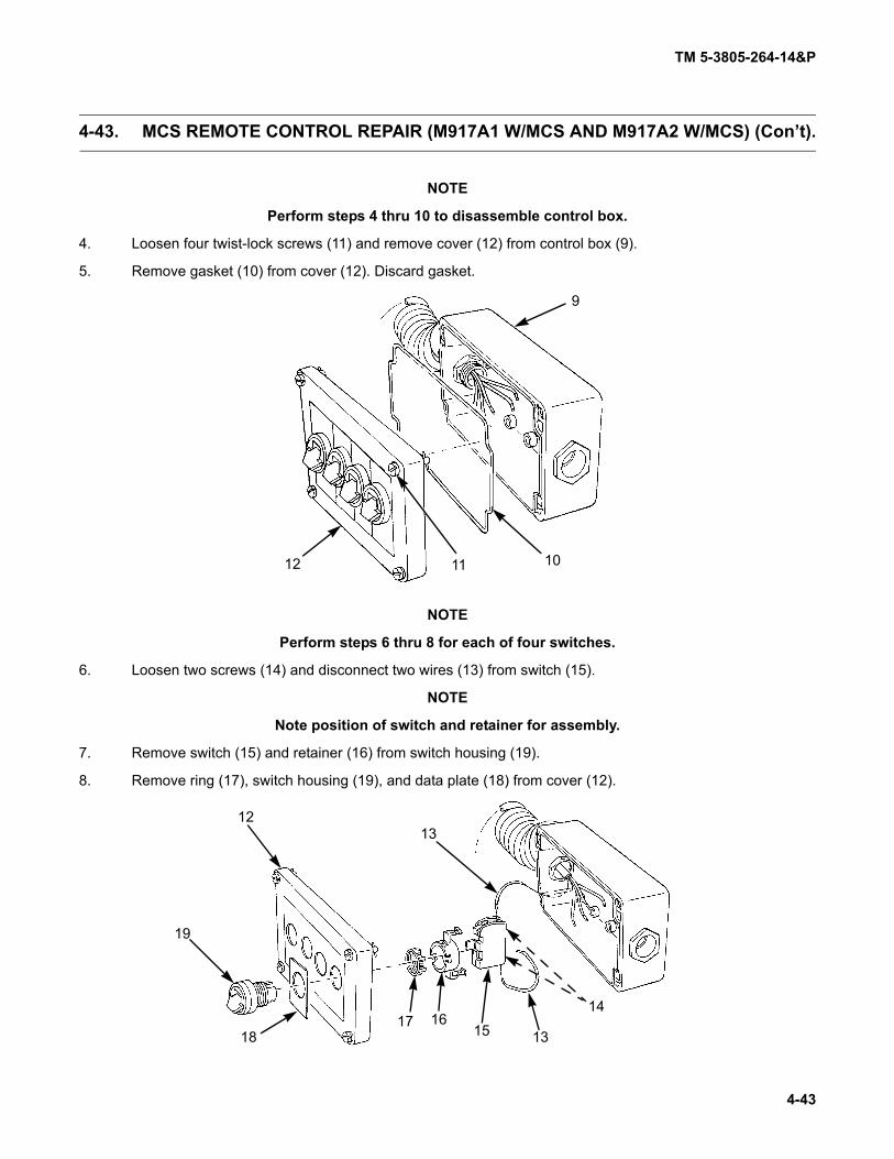
TM 5-3805-264-14&P
4-43
4-43. MCS REMOTE CONTROL REPAIR (M917A1 W/MCS AND M917A2 W/MCS) (Con’t).
NOTE
Perform steps 4 thru 10 to disassemble control box.
4. Loosen four twist-lock screws (11) and remove cover (12) from control box (9).
5. Remove gasket (10) from cover (12). Discard gasket.
NOTE
Perform steps 6 thru 8 for each of four switches.
6. Loosen two screws (14) and disconnect two wires (13) from switch (15).
NOTE
Note position of switch and retainer for assembly.
7. Remove switch (15) and retainer (16) from switch housing (19).
8. Remove ring (17), switch housing (19), and data plate (18) from cover (12).
9
101112
1213
14
13151617
18
19

TM 5-3805-264-14&P
4-44
4-43. MCS REMOTE CONTROL REPAIR (M917A1 W/MCS AND M917A2 W/MCS) (Con’t).
9. Remove locking plug (20), grommet (21), and cable (8) from control box (9).10. Remove nut (22) and bushing (23).
Clean and inspect components in accordance with Chapter 4, Section III, General Maintenance Instruc-tions.
NOTEPerform steps 1 thru 7 to assemble control box.
1. Install bushing (23) and nut (22) to control box (9).2. Install end of cable (8), grommet (21), and locking plug (20).
8
20
21
9
22
23
b. CLEANING AND INSPECTION
c. ASSEMBLY

TM 5-3805-264-14&P
4-45
4-43. MCS REMOTE CONTROL REPAIR (M917A1 W/MCS AND M917A2 W/MCS) (Con’t).
NOTE
Perform steps 3 thru 5 for each of four switches.
3. Install data plate (18), switch housing (19), and ring (17) to cover (12).
4. Install retainer (16) and switch (15) to switch housing (19).
5. Connect two wires (13) to switch (15) and tighten two screws (14).
6. Install new gasket (10) to cover (12).
7. Install cover (12) to control box (9) and tighten four twist-lock screws (11).
1213
14
13151617
18
19
9
101112

TM 5-3805-264-14&P
4-46
4-43. MCS REMOTE CONTROL REPAIR (M917A1 W/MCS AND M917A2 W/MCS) (Con’t).
8. Install jumper wire (7) to connector (5).9. With cable (8) thru connector housing (3), install connector (5) to wires of cable with seven screws (6).
Push connector into connector housing.10. Install clamp (2), screw (1), and screw (4).
FOLLOW-ON TASKS:• Check operation of MCS remote control (paragraph 2-13).
12 3
4
5
6
78

TM 5-3805-264-14&P
4-47
4-44. BODY UP AND TRANSPORT LOCK SWITCHES WIRING HARNESS MAINTENANCE.
This task covers:
a. Removalb. Repair
c. Installation
Initial Setup:
Equipment Conditions:• Dump body raised and supported on body props
(paragraph 2-15).• Batteries disconnected (TM 9-2320-363-20)
(M917A1 and M917A1 w/MCS).• Master battery switch OFF (TM 9-2320-302-10)
(M917A2 and M917A2 w/MCS)Tools/Test Equipment:
• General mechanic’s tool kit (Item 8, Appendix I)
Materials/Parts:
• Marker tags (Item 20, Appendix F)
• Tie wraps (Item 19, Appendix F)
General Safety Instructions:
• NEVER work under a raised dump body unless itis secured in the raised position with body propsand dump body is EMPTY.
WARNING
NEVER work under a raised dump body unless it is secured in the raised positionwith body props and dump body is EMPTY. Failure to follow this warning may resultin death or injury to personnel.
NOTE• Wires should be tagged before disconnecting (paragraph 4-17).• Note location of tie wraps and routing of wiring harness prior to removal to aid
in installation.1. Remove tie wraps and discard.2. Disconnect transport lock switch connector (1) from wiring harness connector (2).
a. REMOVAL
1
2

TM 5-3805-264-14&P
4-48
4-44. BODY UP AND TRANSPORT LOCK SWITCHES WIRING HARNESS MAINTE-NANCE (Con’t).
3. Disconnect two wiring harness leads (5) from body up switch (6).
4. Disconnect wiring harness connector (4) from chassis wiring harness connector (3) and remove wiring har-ness (7).
NOTE
Wiring harness need not be removed from vehicle to make repairs.
Repair wiring harness in accordance with instructions in Chapter 4, Section III, General MaintenanceInstructions.
1. Connect wiring harness connector (4) to chassis wiring harness connector (3).
2. Connect two wiring harness leads (5) to body up switch (6).
3. Connect transport lock switch connector (1) to wiring harness connector (2).
4. Secure wiring harness (7) with new tie wraps.
FOLLOW-ON TASKS:
• Connect batteries (TM 9-2320-363-20) (M917A1 and M917A1 w/MCS).
• Check operation of body up and transport lock switches (paragraph 2-1).
1
2
3
4
5
6
7
b. REPAIR
c. INSTALLATION

TM 5-3805-264-14&P
4-49
4-45. BEACON WARNING LIGHT WIRING HARNESS MAINTENANCE.
This task covers:a. Removalb. Repair
c. Installation
Initial Setup:Equipment Conditions:
• Dump body raised and supported on body props(paragraph 2-15).
• Batteries disconnected (TM 9-2320-363-20)(M917A1 and M917A1 w/MCS).
• Master battery switch OFF (TM 9-2320-302-10)(M917A2 and M917A2 w/MCS)
Tools/Test Equipment:
• General mechanic’s tool kit (Item 8, Appendix I)
Materials/Parts:• Marker tags (Item 20, Appendix F)
Materials/Parts (Con’t):• Locknuts (as required)• Tie wraps (Item 19, Appendix F)
General Safety Instructions:• NEVER work under a raised dump body unless it
is secured in the raised position with body propsand dump body is EMPTY.
WARNING
NEVER work under a raised dump body unless it is secured in the raised positionwith body props and dump body is EMPTY. Failure to follow this warning may resultin death or injury to personnel.
NOTE• Wires should be tagged before disconnecting (paragraph 4-17).• Note location of tie wraps and routing of wiring harness prior to removal to aid
in installation.1. At beacon warning light, disconnect two wiring harness connectors from beacon warning light connectors.
a. REMOVAL

TM 5-3805-264-14&P
4-50
4-45. BEACON WARNING LIGHT WIRING HARNESS MAINTENANCE (Con’t).
2. Remove wiring harness (3) from cab shield grommet (1).3. Remove locknuts (4) and clamps (5) securing wiring harness (3) to welded studs (6) on cab shield (2) and
dump body (9). Discard locknuts.4. Remove wiring harness (3) from grommet (7) at front right side of dump body (9).5. Repeat step 3 to release wiring harness (3) from welded studs on inner surface of right side dump body
frame rail (8). Discard locknuts.
6. Disconnect wiring harness connector (11) from chassis wiring harness connector (10).7. Remove wiring harness (3).
3
7
8
9
65
43
2
1
3
11
10

TM 5-3805-264-14&P
4-51
4-45. BEACON WARNING LIGHT WIRING HARNESS MAINTENANCE (Con’t).
NOTEWiring harness need not be removed from vehicle to make repairs.
Repair wiring harness in accordance with instructions in Chapter 4, Section III, General MaintenanceInstructions.
1. Position wiring harness (3) between points of connection.2. Connect wiring harness connector (11) to chassis wiring harness connector (10).3. Route wiring harness (3) along inner surface of right side dump body frame rail (8) and through grommet
(7) at front of right side dump body (9).4. Route wiring harness (3) up dump body (9) and cab shield (2) Secure with clamps (5) and new locknuts (4)
on welded studs (6).5. Secure wiring harness (3) along inner surface of right side dump body frame rail (8) with clamps (5) and
new locknuts (4) on welded studs (6).6. Install wiring harness (3) through cab shield grommet (1).7. Install new tie wraps.
FOLLOW-ON TASKS:• Connect batteries (TM 9-2320-363-20) (M917A1 and M917A1 w/MCS).• Remove body props and lower dump body (paragraph 2-15).• Check operation of beacon warning light (TM 9-2320-363-10 or TM 9-2320-302-10).
b. REPAIR
c. INSTALLATION

TM 5-3805-264-14&P
4-52
4-46. LIGHTS WIRING HARNESS MAINTENANCE.
This task covers:
a. Removalb. Repair
c. Installation
Initial Setup:
Equipment Conditions:
• Dump body raised and supported on body props(paragraph 2-15).
• Batteries disconnected (TM 9-2320-363-20)(M917A1 and M917A1 w/MCS).
• Master battery switch OFF (TM 9-2320-302-10)(M917A2 and M917A2 w/MCS)
Tools/Test Equipment:
• General mechanic’s tool kit (Item 8, Appendix I)
Materials/Parts:• Marker tags (Item 20, Appendix F)• Tie wraps (Item 19, Appendix F)
References:• TM 9-2320-363-20• TM 9-2320-302-20
General Safety Instructions:• NEVER work under a raised dump body unless it
is secured in the raised position with body propsand dump body is EMPTY.
WARNING
NEVER work under a raised dump body unless it is secured in the raised positionwith body props and dump body is EMPTY. Failure to follow this warning may resultin death or injury to personnel.
NOTE• Wires should be tagged before disconnecting (paragraph 4-17).• Note location of tie wraps and routing of wiring harness prior to removal to aid
in installation.1. Remove two wiring harness terminal leads from backup alarm (TM 9-2320-363-20 or TM 9-2320-302-20).2. Remove taillight from each side of dump body and disconnect wiring harness (paragraph 4-40).3. Remove marker clearance light from each side of dump body and disconnect wiring harness (paragraph 4-
41).4. Disconnect wiring harness leads (2) from three marker clearance lights (3) at rear hinge light bracket (7).5. Disconnect wiring harness connector (5) from chassis wiring harness connector (6) and remove wiring har-
ness (4) from dump body (1).
NOTEWiring harness need not be removed from vehicle to make repairs.
Repair wiring harness in accordance with instructions in Chapter 4, Section III, General MaintenanceInstructions.
a. REMOVAL
b. REPAIR

TM 5-3805-264-14&P
4-53
4-46. LIGHTS WIRING HARNESS MAINTENANCE (Con’t).
1. Position wiring harness (4) between points of connection, routing it along channels and openings in dumpbody (1).
2. Connect wiring harness connector (5) to chassis wiring harness connector (6).
3. Connect wiring harness leads (2) to three marker clearance lights (3) at rear hinge light bracket (7).
4. Connect wiring harness to each taillight and install taillights (paragraph 4-40).
5. Connect wiring harness to marker clearance light on each side of dump body and install lights (paragraph4-41).
6. Install two wiring harness terminal leads to backup alarm (TM 9-2320-363-20 or TM 9-2320-302-20).
7. Install new tie wraps.
FOLLOW-ON TASKS:
• Connect batteries (TM 9-2320-363-20) (M917A1 and M917A1 w/MCS).
• Remove body props and lower dump body (paragraph 2-15).
• Check operation of dump body lights and backup alarm (TM 9-2320-363-10 or TM 9-2320-302-10).
1
2 3 4
5
3
6
7
c. INSTALLATION

TM 5-3805-264-14&P
4-54
4-47. TRUCK-TO-MCS TAILGATE WIRING HARNESS MAINTENANCE (M917A1 W/MCS AND M917A2 W/MCS).
This task covers:
a. Removalb. Repair
c. Installation
Initial Setup:
Equipment Conditions:• Dump body raised and supported on body props
(paragraph 2-15).• Batteries disconnected (TM 9-2320-363-20)
(M917A1 and M917A1 w/MCS).• Master battery switch OFF (TM 9-2320-302-10)
(M917A2 and M917A2 w/MCS)
Tools/Test Equipment:• General mechanic’s tool kit (Item 8, Appendix I)
Materials/Parts:
• Tie wraps (Item 19, Appendix F)• Marker tags (Item 20, Appendix F)• Two self-locking nuts
General Safety Instructions:
• NEVER work under a raised dump body unless itis secured in the raised position with body propsand dump body is EMPTY.
WARNING
NEVER work under a raised dump body unless it is secured in the raised positionwith body props and dump body is EMPTY. Failure to follow this warning may resultin death or injury to personnel.
NOTE• Wires should be tagged before disconnecting (paragraph 4-17).• Note location of tie wraps and routing of wiring harness prior to removal to aid
in installation.1. Disconnect MCS tailgate wiring harness connector (3) from truck-to-MCS tailgate wiring harness recepta-
cle (2) at left dump body pillar (1).
a. REMOVAL
1 23

TM 5-3805-264-14&P
4-55
4-47. TRUCK-TO-MCS TAILGATE WIRING HARNESS MAINTENANCE (M917A1 W/MCS AND M917A2 W/MCS) (Con’t).
2. Remove four screws (7) and pull cover plate(5) away from dump body pillar (1).
3. Remove two self-locking nuts (4) and screws(6) securing truck-to-MCS tailgate wiring har-ness receptacle (2) to cover plate (5). Discardself-locking nuts.
4. Disconnect truck-to-MCS tailgate wiring harness (9) from chassis wiring harness (8).
5. Remove truck-to-MCS tailgate wiring harness (9).
1 54
2 6
7
9
8

TM 5-3805-264-14&P
4-56
4-47. TRUCK-TO-MCS TAILGATE WIRING HARNESS MAINTENANCE (M917A1 W/MCS AND M917A2 W/MCS) (Con’t).
NOTEWiring harness need not be removed from vehicle to make repairs.
Repair wiring harness in accordance with instructions in Chapter 4, Section III, General MaintenanceInstructions.
1. Position truck-to-MCS tailgate wiring harness (9) between points of connection.2. Connect truck-to-MCS tailgate wiring harness (9) to chassis wiring harness (8).
3. Position truck-to-MCS tailgate wiring harnessreceptacle (2) against cover plate (5). Securewith two screws (6) and new self-locking nuts(4).
4. Install cover plate (5) to dump body pillar (1)with four screws (7).
b. REPAIR
c. INSTALLATION
9
8
1 54
2 6
7

TM 5-3805-264-14&P
4-57
4-47. TRUCK-TO-MCS TAILGATE WIRING HARNESS MAINTENANCE (M917A1 W/MCS AND M917A2 W/MCS) (Con’t).
5. Connect MCS tailgate wiring harness connector (3) to truck-to-MCS tailgate wiring harness receptacle (2).
6. Install new tie wraps.
FOLLOW-ON TASKS:• Connect batteries (TM 9-2320-363-20) (M917A1 and M917A1 w/MCS).• Remove body props and lower dump body (paragraph 2-15).• Check operation of MCS tailgate using cab-mounted MCS control unit and remote
control (paragraphs 2-1 and 2-2).
1 23

TM 5-3805-264-14&P
4-58
4-48. MCS TAILGATE WIRING HARNESS MAINTENANCE (M917A1 W/MCS AND M917A2 W/MCS).
This task covers:
a. Removalb. Repair
c. Installation
Initial Setup:
Equipment Conditions:
• Batteries disconnected (TM 9-2320-363-20)(M917A1 and M917A1 w/MCS).
• Master battery switch OFF (TM 9-2320-302-10)(M917A2 and M917A2 w/MCS)
• MCS tailgate cover removed (paragraph 4-53).
Tools/Test Equipment:
• General mechanic’s tool kit (Item 8, Appendix I)
Materials/Parts:
• Marker tags (Item 20, Appendix F)• Four self-locking nuts• Tie wraps (Item 19, Appendix F)
NOTE• Wires should be tagged before disconnecting (paragraph 4-17).
• Note location of tie wraps and routing of wiring harness prior to removal to aidin installation.
1. Disconnect wiring harness connector (3) from truck-to-MCS tailgate wiring harness receptacle (2) at leftdump body pillar (1).
a. REMOVAL
1 23
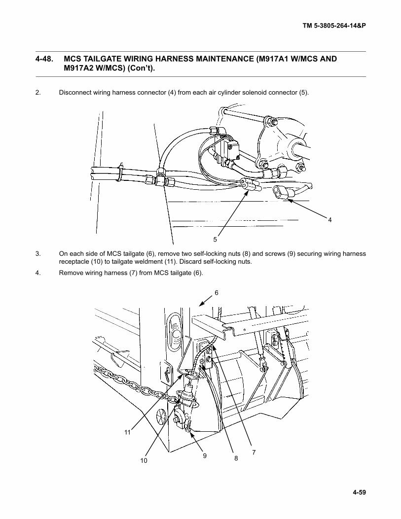
TM 5-3805-264-14&P
4-59
4-48. MCS TAILGATE WIRING HARNESS MAINTENANCE (M917A1 W/MCS AND M917A2 W/MCS) (Con’t).
2. Disconnect wiring harness connector (4) from each air cylinder solenoid connector (5).
3. On each side of MCS tailgate (6), remove two self-locking nuts (8) and screws (9) securing wiring harnessreceptacle (10) to tailgate weldment (11). Discard self-locking nuts.
4. Remove wiring harness (7) from MCS tailgate (6).
4
5
6
789
10
11

TM 5-3805-264-14&P
4-60
4-48. MCS TAILGATE WIRING HARNESS MAINTENANCE (M917A1 W/MCS AND M917A2 W/MCS) (Con’t).
NOTEWiring harness need not be removed from vehicle to make repairs.
Repair wiring harness in accordance with instructions in Chapter 4, Section III, General MaintenanceInstructions.
1. Position wiring harness (7) on MCS tailgate (6) between points of connection.2. On each side of MCS tailgate (6), position wiring harness receptacle (10) on tailgate weldment (11) and
secure with two screws (9) and new self-locking nuts (8).
b. REPAIR
c. INSTALLATION
6
789
10
11

TM 5-3805-264-14&P
4-61
4-48. MCS TAILGATE WIRING HARNESS MAINTENANCE (M917A1 W/MCS AND M917A2 W/MCS) (Con’t).
3. Connect wiring harness connector (4) to each air cylinder solenoid connector (5).
4. Connect wiring harness connector (3) to truck-to-MCS tailgate wiring harness receptacle (2) at left dumpbody pillar (1).
5. Install new tie wraps.
FOLLOW-ON TASKS:• Connect batteries (TM 9-2320-363-20) (M917A1 and M917A1 w/MCS).• Start vehicle and pressurize air system (TM 9-2320-363-10 or TM 9-2320-302-10).• Check operation of MCS tailgate using cab-mounted MCS control unit and remote
control (paragraphs 2-1 and 2-2).• Install MCS tailgate cover (paragraph 4-53).
4
5
1 23

TM 5-3805-264-14&P
4-62
4-49. WIRING DIAGRAMS.
PTO LOCKOUT

TM 5-3805-264-14&P
4-63
4-49. WIRING DIAGRAMS (Con’t).
MCS (M917A1 W/MCS AND M917A2 W/MCS)

TM 5-3805-264-14&P
4-64
4-49. WIRING DIAGRAMS (Con’t).
BODY UPSWITCH
TRANSPORTLOCK SWITCH
GR
BU
BR
BK
D
C
BA
ONTRUCK
CHASSISWIRING
HARNESS
GRBUBRBL
GREENBLUE
BROWNBLACK
BODY UP AND TRANSPORT LOCK SWITCHES
BEACONWARNING
LIGHT
ON TRUCKCHASSISWIRING
HARNESS
A
B
BK
WH
BKWH
BLACKWHITE
BEACON WARNING LIGHT

TM 5-3805-264-14&P
4-65
4-49. WIRING DIAGRAMS (Con’t).
MARKER
LIGHT
YE
BRGR
WH
LIGHT CLUSTER
A B C D E
WIRING HARNESS
GR GREEN
LEFT SIDE
CLEARANCE
ON TRUCK CHASSIS
RIGHT SIDE
YELLOW
BR
WH
BROWN
WHITEYE
TAILLIGHT
DUMP BODY TAILLIGHTS AND MARKERCLEARANCE LIGHTS
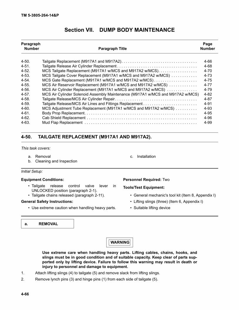
TM 5-3805-264-14&P
4-66
Section VII. DUMP BODY MAINTENANCE
Paragraph PageNumber Paragraph Title Number
4-50. Tailgate Replacement (M917A1 and M917A2). . . . . . . . . . . . . . . . . . . . . . . . . . . . . . . . . . . 4-664-51. Tailgate Release Air Cylinder Replacement . . . . . . . . . . . . . . . . . . . . . . . . . . . . . . . . . . . . . 4-684-52. MCS Tailgate Replacement (M917A1 w/MCS and M917A2 w/MCS). . . . . . . . . . . . . . . . . . 4-704-53. MCS Tailgate Cover Replacement (M917A1 w/MCS and M917A2 w/MCS) . . . . . . . . . . . . 4-734-54. MCS Gate Replacement (M917A1 w/MCS and M917A2 w/MCS) . . . . . . . . . . . . . . . . . . . . 4-754-55. MCS Air Reservoir Replacement (M917A1 w/MCS and M917A2 w/MCS) . . . . . . . . . . . . . 4-774-56. MCS Air Cylinder Replacement (M917A1 w/MCS and M917A2 w/MCS) . . . . . . . . . . . . . . 4-794-57. MCS Air Cylinder Solenoid Assembly Maintenance (M917A1 w/MCS and M917A2 w/MCS) 4-824-58. Tailgate Release/MCS Air Cylinder Repair . . . . . . . . . . . . . . . . . . . . . . . . . . . . . . . . . . . . . . 4-874-59. Tailgate Release/MCS Air Lines and Fittings Replacement . . . . . . . . . . . . . . . . . . . . . . . . . 4-914-60. MCS Adjustment Tube Replacement (M917A1 w/MCS and M917A2 w/MCS) . . . . . . . . . . 4-934-61. Body Prop Replacement. . . . . . . . . . . . . . . . . . . . . . . . . . . . . . . . . . . . . . . . . . . . . . . . . . . . 4-954-62. Cab Shield Replacement . . . . . . . . . . . . . . . . . . . . . . . . . . . . . . . . . . . . . . . . . . . . . . . . . . . 4-964-63. Mud Flap Replacement . . . . . . . . . . . . . . . . . . . . . . . . . . . . . . . . . . . . . . . . . . . . . . . . . . . . 4-99
4-50. TAILGATE REPLACEMENT (M917A1 AND M917A2).
This task covers:
a. Removalb. Cleaning and Inspection
c. Installation
Initial Setup:
Equipment Conditions:• Tailgate release control valve lever in
UNLOCKED position (paragraph 2-1).• Tailgate chains released (paragraph 2-11).
General Safety Instructions:• Use extreme caution when handling heavy parts.
Personnel Required: Two
Tools/Test Equipment:
• General mechanic's tool kit (Item 8, Appendix I)• Lifting slings (three) (Item 6, Appendix I)• Suitable lifting device
WARNING
Use extreme care when handling heavy parts. Lifting cables, chains, hooks, andslings must be in good condition and of suitable capacity. Keep clear of parts sup-ported only by lifting device. Failure to follow this warning may result in death orinjury to personnel and damage to equipment.
1. Attach lifting slings (4) to tailgate (5) and remove slack from lifting slings.2. Remove lynch pins (3) and hinge pins (1) from each side of tailgate (5).
a. REMOVAL

TM 5-3805-264-14&P
4-67
4-50. TAILGATE REPLACEMENT (M917A1 AND M917A2) (Con’t).
3. Lift tailgate (5) from dump body (2) and place tailgate in a safe work area.
Clean and inspect components in accordance with Chapter 4, Section III, General Maintenance Instruc-tions.
WARNING
Use extreme care when handling heavy parts. Lifting cables, chains, hooks, andslings must be in good condition and of suitable capacity. Keep clear of parts sup-ported only by lifting device. Failure to follow this warning may result in death orinjury to personnel and damage to equipment.
1. Raise tailgate (5) to dump body (2).2. Position tailgate (5) so that bottom pins (6) are resting on dump body stops (7) and tailgate hinge pin holes
are alined with dump body hinge pin holes.3. Install hinge pins (1) and lynch pins (3) to each side of tailgate (5).4. Remove lifting slings (4) from tailgate (5).FOLLOW-ON TASKS:
• Lubricate tailgate hinge pins (Chapter 3, Section I).• Start engine and pressurize air systems (TM 9-2320-363-10 or TM 9-2320-302-10).• Set tailgate release control valve lever to LOCKED position (paragraph 2-1).• Latch tailgate chains (paragraph 2-11).
67
54321
b. CLEANING AND INSPECTION
c. INSTALLATION

TM 5-3805-264-14&P
4-68
4-51. TAILGATE RELEASE AIR CYLINDER REPLACEMENT.
This task covers:
a. Removalb. Cleaning and Inspection
c. Installation
Initial Setup:
Equipment Conditions:
• Tailgate release control valve lever inUNLOCKED position (paragraph 2-1).
• Dump body raised and supported on body props(paragraph 2-15).
• Chassis air system drained (TM 9-2320-363-10or TM 9-2320-302-10).
Tools/Test Equipment:
• General mechanic’s tool kit (Item 8, Appendix I)
Materials/Parts:• Marker tags (Item 20, Appendix F)• Two cotter pins
Personnel Required: TwoGeneral Safety Instructions:
• NEVER work under a raised dump body unless itis secured in the raised position with body propsand dump body is EMPTY.
• DO NOT disconnect air lines while air system ispressurized.
WARNING
• NEVER work under a raised dump body unless it is secured in the raised posi-tion with body props and dump body is EMPTY. Failure to follow this warningmay result in death or injury to personnel.
• DO NOT disconnect air lines while air system is pressurized. Air system pres-sure must be released before air lines are disconnected. A line disconnectedunder pressure may cause personnel injury.
NOTEHoses should be tagged before removal (paragraph 4-17).
1. Disconnect two air lines (4) from two elbows (3) and remove elbows from air cylinder (5).
NOTENote position of nut at air cylinder piston shaft clevis to ensure proper adjustmentof air cylinder on installation.
2. Remove cotter pin (8) and pin (6) to remove air cylinder (5) from tailgate release lever (7). Discard cotterpin.
3. Remove cotter pin (9) and pin (2) to remove air cylinder (5) from dump body (1). Discard cotter pin.
Clean and inspect components in accordance with Chapter 4, Section III, General Maintenance Instruc-tions.
a. REMOVAL
b. CLEANING AND INSPECTION

TM 5-3805-264-14&P
4-69
4-51. TAILGATE RELEASE AIR CYLINDER REPLACEMENT (Con’t).
1. Install air cylinder (5) to dump body (1) with pin (2) and new cotter pin (9).
NOTE
Ensure that position of nut at air cylinder piston shaft clevis is the same as notedduring removal, to ensure proper adjustment of air cylinder on installation.
2. Install air cylinder (5) to tailgate release lever (7) with pin (6) and new cotter pin (8).
3. Install two elbows (3) to air cylinder (5). Connect two air lines (4) to elbows.
FOLLOW-ON TASKS:
• Start engine and pressurize air system (TM 9-2320-363-10 or TM 9-2320-302-10).
• Remove body props and lower dump body (paragraph 2-15).
• Set tailgate release control valve lever to LOCKED position (paragraph 2-1).
9
8
67
5
4
3
2
1
c. INSTALLATION

TM 5-3805-264-14&P
4-70
4-52. MCS TAILGATE REPLACEMENT (M917A1 W/MCS AND M917A2 W/MCS).
This task covers:
a. Removalb. Cleaning and Inspection
c. Installation
Initial Setup:
Equipment Conditions:
• MCS remote control disconnected (paragraph 2-2).
• Tailgate release control valve lever inUNLOCKED position (paragraph 2-1).
• Chassis air system drained (TM 9-2320-363-10or TM 9-2320-302-10).
• MCS air system drained (Chapter 2, Section II,Operator PMCS).
• Tailgate chains released (paragraph 2-11).
Tools/Test Equipment:• General mechanic's tool kit (Item 8, Appendix I)• Lifting slings (three) (Item 6, Appendix I)• Suitable lifting device
Personnel Required: Two
General Safety Instructions:• DO NOT disconnect air lines while air system is
pressurized.• Use extreme caution when handling heavy parts.
1. Disconnect MCS tailgate wiring harness connector (3) from receptacle (10).
WARNING
DO NOT disconnect air lines while air system is pressurized. Air system pressuremust be released before air lines are disconnected. A line disconnected under pres-sure may cause personnel injury.
2. Disconnect MCS quick-disconnect air line (9).
WARNING
Use extreme care when handling heavy parts. Lifting cables, chains, hooks, andslings must be in good condition and of suitable capacity. Keep clear of parts sup-ported only by lifting device. Failure to follow this warning may result in death orinjury to personnel and damage to equipment.
3. Attach lifting slings (4) to MCS tailgate (5) and remove slack from lifting slings.
4. Remove lynch pins (2) and hinge pins (1) from each side of MCS tailgate (5).
5. Lift MCS tailgate (5) from dump body (8) and place tailgate in a safe work area.
Clean and inspect components in accordance with Chapter 4, Section III, General Maintenance Instruc-tions.
a. REMOVAL
b. CLEANING AND INSPECTION

TM 5-3805-264-14&P
4-71
4-52. MCS TAILGATE REPLACEMENT (M917A1 W/MCS AND M917A2 W/MCS) (Con’t).
WARNING
Use extreme care when handling heavy parts. Lifting cables, chains, hooks, andslings must be in good condition and of suitable capacity. Keep clear of parts sup-ported only by lifting device. Failure to follow this warning may result in death orinjury to personnel and damage to equipment.
1. Raise MCS tailgate (5) to dump body (8).
8
9
10
1
2
35
4
c. INSTALLATION

TM 5-3805-264-14&P
4-72
4-52. MCS TAILGATE REPLACEMENT (M917A1 W/MCS AND M917A2 W/MCS) (Con’t).
2. Position MCS tailgate (5) so that bottom pins (7) are resting on dump body stops (6) and tailgate hinge pinholes are alined with dump body hinge pin holes.
3. Install hinge pins (1) and lynch pins (2) to each side of MCS tailgate (5).
4. Remove lifting slings (4) from MCS tailgate (5).
5. Connect MCS quick-disconnect air line (9).
6. Connect MCS tailgate wiring harness connector (3) to receptacle (10).
FOLLOW-ON TASKS:• Lubricate tailgate hinge pins (Chapter 3, Section I).• Start engine and pressurize air systems (TM 9-2320-363-10 or TM 9-2320-302-10).• Set tailgate release control valve lever to LOCKED position (paragraph 2-1).• Check operation of MCS gates using cab-mounted control unit (paragraph 2-1).• Check operation of MCS gates using MCS remote control (paragraph 2-2).• Latch tailgate chains (paragraph 2-11).
67
8
9
10
1
2
35
4

TM 5-3805-264-14&P
4-73
4-53. MCS TAILGATE COVER REPLACEMENT (M917A1 W/MCS AND M917A2 W/MCS).
This task covers:a. Removalb. Cleaning and Inspection
c. Installation
Initial Setup:Tools/Test Equipment:
• General mechanic's tool kit (Item 8, Appendix I)Materials/Parts:
• One self-locking nut
Personnel Required: TwoGeneral Safety Instructions:
• Use extreme caution when handling heavy parts.
WARNING
Use extreme care when handling heavy parts. Lifting cables, chains, hooks, andslings must be in good condition and of suitable capacity. Keep clear of parts sup-ported only by lifting device. Failure to follow this warning may result in death orinjury to personnel and damage to equipment.
1. Remove self-locking nut, screw, clamp, and release air reservoir draincock lanyard (4) from MCS tailgatecover (2). Discard self-locking nut.
2. Remove ten self-tapping screws (3) and MCS tailgate cover (2) from MCS tailgate (1).
a. REMOVAL
1 2 3
4
3

TM 5-3805-264-14&P
4-74
4-53. MCS TAILGATE COVER REPLACEMENT (M917A1 W/MCS AND M917A2 W/MCS) (Con’t).
Clean and inspect components in accordance with Chapter 4, Section III, General Maintenance Instruc-tions.
1. Aline screw holes on MCS tailgate cover (2) with screw holes on MCS tailgate (1).
2. Install and tighten ten self-tapping screws (3).
3. Secure air reservoir draincock lanyard (4) to MCS tailgate cover (2) with clamp, screw, and new self-lock-ing nut.
b. CLEANING AND INSPECTION
c. INSTALLATION
1 23
4
3

TM 5-3805-264-14&P
4-75
4-54. MCS GATE REPLACEMENT (M917A1 W/MCS AND M917A2 W/MCS).
This task covers:
a. Removalb. Cleaning and Inspection
c. Installation
Initial Setup:
Equipment Conditions:• MCS adjustment tube removed (paragraph 4-
60).• MCS air cylinder removed (paragraph 4-56).
Tools/Test Equipment:• General mechanic's tool kit (Item 8, Appendix I)
Materials/Parts:• Four lockwashers
Personnel Required: Two
1. Remove four screws (3), lockwashers (2), MCS gate (4), and two brackets (1) from tailgate (5). Discardlockwashers.
2. Remove two brackets (1) from MCS gate (4).
Clean and inspect components in accordance with Chapter 4, Section III, General Maintenance Instruc-tions.
a. REMOVAL
1 2 3 1
23
4
5
b. CLEANING AND INSPECTION
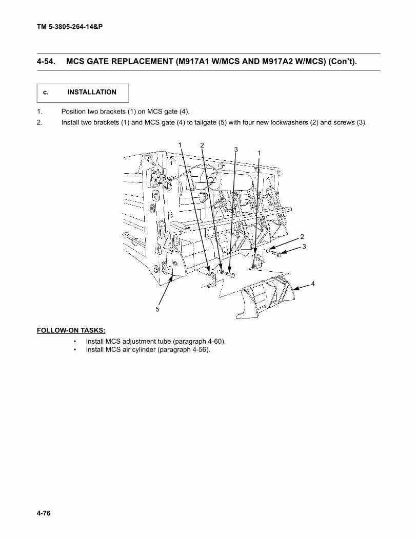
TM 5-3805-264-14&P
4-76
4-54. MCS GATE REPLACEMENT (M917A1 W/MCS AND M917A2 W/MCS) (Con’t).
1. Position two brackets (1) on MCS gate (4).2. Install two brackets (1) and MCS gate (4) to tailgate (5) with four new lockwashers (2) and screws (3).
FOLLOW-ON TASKS:• Install MCS adjustment tube (paragraph 4-60).• Install MCS air cylinder (paragraph 4-56).
c. INSTALLATION
1 2 3 1
23
4
5

TM 5-3805-264-14&P
4-77
4-55. MCS AIR RESERVOIR REPLACEMENT (M917A1 W/MCS AND M917A2 W/MCS).
This task covers:
a. Removal b. Installation
Initial Setup:
Equipment Conditions:• Chassis air system drained (TM 9-2320-363-10
or TM 9-2320-302-10).• MCS air system drained (Chapter 2, Section II,
Operator PMCS).• MCS tailgate cover removed (paragraph 4-53).
Tools/Test Equipment:• General mechanic's tool kit (Item 8, Appendix I)
Materials/Parts:
• Marker tags (Item 20, Appendix F)• Four locknuts
Personnel Required: Two
General Safety Instructions:
• DO NOT disconnect air lines while air system ispressurized.
WARNING
DO NOT disconnect air lines while air system is pressurized. Air system pressuremust be released before air lines are disconnected. A line disconnected under pres-sure may cause personnel injury.
NOTEHoses should be tagged before removal (paragraph 4-17).
1. Disconnect air supply hose (2) from adapter (3).
a. REMOVAL
2 3

TM 5-3805-264-14&P
4-78
4-55. MCS AIR RESERVOIR REPLACEMENT (M917A1 W/MCS AND M917A2 W/MCS) (Con’t).
2. Disconnect air hose (4) from adapter (8).3. Remove four locknuts (14), flatwashers (15), screws (10), and air reservoir (11) from welded brackets (1).
Discard locknuts.4. Remove adapter (3), bushing (5), check valve (6), elbow (7), and reducer (9) from air reservoir (11).5. Remove adapter (8) from air reservoir (11).6. Remove draincock with lanyard (13) and plug (12) from air reservoir (11).
1. Install draincock with lanyard (13) and plug (12) to air reservoir (11).2. Install adapter (8) to air reservoir (11).3. Install reducer (9), elbow (7), check valve (6), bushing (5), and adapter (3) to air reservoir (11).4. Install air reservoir (11) to welded brackets (1) with four screws (10), flatwashers (15), and new locknuts
(14).5. Connect air hose (4) to adapter (8).6. Connect air supply hose (2) to adapter (3).
FOLLOW-ON TASKS:• Start engine and pressurize air systems (TM 9-2320-363-10 or TM 9-2320-302-10).• Check for leaks.• Check operation of MCS tailgate (paragraph 2-13).• Install MCS tailgate cover (paragraph 4-53).
b. INSTALLATION
14
15
1
13
12
1110
987654
32
1

TM 5-3805-264-14&P
4-79
4-56. MCS AIR CYLINDER REPLACEMENT (M917A1 W/MCS AND M917A2 W/MCS).
This task covers:a. Removalb. Cleaning and Inspection
c. Installation
Initial Setup:Equipment Conditions:
• Chassis air system drained (TM 9-2320-363-10or TM 9-2320-302-10).
• MCS air system drained (Chapter 2, Section II,Operator PMCS).
• MCS tailgate cover removed (paragraph 4-53).Tools/Test Equipment:
• General mechanic's tool kit (Item 8, Appendix I)
Materials/Parts:
• Tie wraps (Item 19, Appendix F)
Personnel Required: Two
General Safety Instructions:
• DO NOT disconnect air lines while air system ispressurized.
WARNING
DO NOT disconnect air lines while air system is pressurized. Air system pressuremust be released before air lines are disconnected. A line disconnected under pres-sure may cause personnel injury.
NOTENote location of tie wraps prior to removal to aid in installation.
1. Disconnect solenoid connector (5) from MCS tailgate wiring harness connector (4).2. Disconnect air line (1) from elbow (2). If damaged, remove elbow from air cylinder solenoid (3).
a. REMOVAL
1
2 3
45

TM 5-3805-264-14&P
4-80
4-56. MCS AIR CYLINDER REPLACEMENT (M917A1 W/MCS AND M917A2 W/MCS) (Con’t).
3. Remove retaining pin (10) and pin (12) to disconnect air cylinder (9) from MCS gate (11).NOTE
Note position of nut at air cylinder piston shaft clevis to ensure proper adjustmentof air cylinder on installation.
4. Remove retaining pin (8) and pin (6) to disconnect air cylinder (9) from MCS tailgate (7).
Clean and inspect components in accordance with Chapter 4, Section III, General Maintenance Instruc-tions.
NOTEEnsure that position of nut at air cylinder piston shaft clevis is the same as notedduring removal, to ensure proper adjustment of air cylinder on installation.
1. Install air cylinder (9) to MCS tailgate (7) with pin (6) and new retaining pin (8).2. Install air cylinder (9) to MCS gate (11) with pin (12) and new retaining pin (10).
1211
10
9876
b. CLEANING AND INSPECTION
c. INSTALLATION

TM 5-3805-264-14&P
4-81
4-56. MCS AIR CYLINDER REPLACEMENT (M917A1 W/MCS AND M917A2 W/MCS) (Con’t).
3. If removed, install elbow (2) to air cylinder sole-noid (3). Connect air line (1) to elbow.
4. Connect solenoid connector (5) to MCS tail-gate wiring harness connector (4).
5. Install new tie wraps as required.
FOLLOW-ON TASKS:• Start engine and pressurize air systems (TM 9-2320-363-10 or TM 9-2320-302-10).• Check for leaks.• Check operation of MCS tailgate (paragraph 2-13).• Install MCS tailgate cover (paragraph 4-53).
1
2
3
4
5

TM 5-3805-264-14&P
4-82
4-57. MCS AIR CYLINDER SOLENOID ASSEMBLY MAINTENANCE (M917A1 W/MCS AND M917A2 W/MCS).
This task covers:
a. Removalb. Disassemblyc. Cleaning and Inspection
d. Assemblye. Installation
Initial Setup:
Equipment Conditions:• MCS air cylinder removed (paragraph 4-56).
Tools/Test Equipment:• General mechanic's tool kit (Item 8, Appendix I)
Materials/Parts:
• Pipe sealing compound (Item 7, Appendix F)• Ball bearing grease (Item 12, Appendix F)• One solenoid repair kit
NOTENote position of elbows, tubes, and solenoid assembly to aid in installation.
1. Disconnect tube (1) from fitting (3) on solenoid assembly (2).2. Remove solenoid assembly (2) from air cylinder (4).
1. Remove two filters (6) and elbow (7) from valve body (5).
a. REMOVAL
4
3
2
1
b. DISASSEMBLY
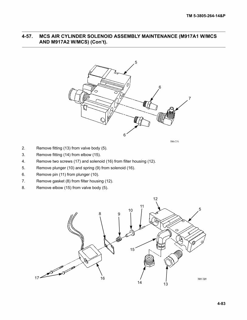
TM 5-3805-264-14&P
4-83
4-57. MCS AIR CYLINDER SOLENOID ASSEMBLY MAINTENANCE (M917A1 W/MCS AND M917A2 W/MCS) (Con’t).
2. Remove fitting (13) from valve body (5).3. Remove fitting (14) from elbow (15).4. Remove two screws (17) and solenoid (16) from filter housing (12).5. Remove plunger (10) and spring (9) from solenoid (16).6. Remove pin (11) from plunger (10).7. Remove gasket (8) from filter housing (12).8. Remove elbow (15) from valve body (5).
5
6
6
7
17 16
8 910
11
12
5
1314
15

TM 5-3805-264-14&P
4-84
4-57. MCS AIR CYLINDER SOLENOID ASSEMBLY MAINTENANCE (M917A1 W/MCS AND M917A2 W/MCS) (Con’t).
9. Remove two screws (18), filter housing (12), and metal gasket (20) from valve body (5).10. Remove gasket (19) from filter housing (12).11. Remove gasket (21) from valve body (5).
12. Remove two screws (23) and end cap (22) from valve body (5).13. Remove gasket (24) and plastic insert (25) from end cap (22).14. Remove valve (26) from valve body (5).
5
21
201918
12
5
22
23
24
25
26
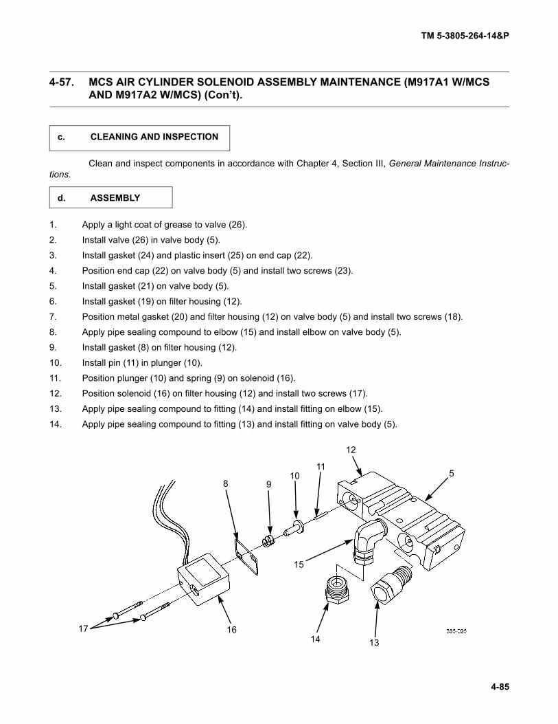
TM 5-3805-264-14&P
4-85
4-57. MCS AIR CYLINDER SOLENOID ASSEMBLY MAINTENANCE (M917A1 W/MCS AND M917A2 W/MCS) (Con’t).
Clean and inspect components in accordance with Chapter 4, Section III, General Maintenance Instruc-tions.
1. Apply a light coat of grease to valve (26).
2. Install valve (26) in valve body (5).
3. Install gasket (24) and plastic insert (25) on end cap (22).
4. Position end cap (22) on valve body (5) and install two screws (23).
5. Install gasket (21) on valve body (5).
6. Install gasket (19) on filter housing (12).
7. Position metal gasket (20) and filter housing (12) on valve body (5) and install two screws (18).
8. Apply pipe sealing compound to elbow (15) and install elbow on valve body (5).
9. Install gasket (8) on filter housing (12).
10. Install pin (11) in plunger (10).
11. Position plunger (10) and spring (9) on solenoid (16).
12. Position solenoid (16) on filter housing (12) and install two screws (17).
13. Apply pipe sealing compound to fitting (14) and install fitting on elbow (15).
14. Apply pipe sealing compound to fitting (13) and install fitting on valve body (5).
c. CLEANING AND INSPECTION
d. ASSEMBLY
17 16
8 910
11
12
5
1314
15

TM 5-3805-264-14&P
4-86
4-57. MCS AIR CYLINDER SOLENOID ASSEMBLY MAINTENANCE (M917A1 W/MCS AND M917A2 W/MCS) (Con’t).
15. Apply pipe sealing compound to elbow (7) and install elbow on valve body (5)16. Install two filters (6) on valve body (5).
1. Install solenoid assembly (2) to air cylinder (4).2. Connect tube (1) to fitting (3) on solenoid assembly (2).
FOLLOW-ON TASKS:• Install MCS air cylinder (paragraph 4-56).
5
6
6
7
e. INSTALLATION
4
3
2
1

TM 5-3805-264-14&P
4-87
4-58. TAILGATE RELEASE/MCS AIR CYLINDER REPAIR.
This task covers:
a. Disassemblyb. Cleaning and Inspection
c. Assembly
Initial Setup:
Equipment Conditions:• Tailgate release/MCS air cylinder removed (para-
graph 4-51 or 4-56).• MCS air cylinder solenoid assembly removed
(paragraph 4-57).Tools/Test Equipment:
• General mechanic's tool kit (Item 8, Appendix I)
Materials/Parts:
• Ball bearing grease (Item 12, Appendix F)
1. Remove tube (11) from elbow (12).2. Remove elbow (12) from top end plate (3).3. Remove four screws (1) and mounting bracket (2) from top end plate (3).
NOTENote position of nut at air cylinder piston shaft clevis during removal to ensureproper adjustment of air cylinder during installation.
4. Remove clevis (8) and nut (7) from piston shaft (5).5. Remove four retaining nuts (9) and lockwashers (10) from tie rods (4).6. Remove top end plate (3) with tie rods attached from bottom end plate (6).7. Separate bottom end plate (6) from piston shaft (5).8. Remove tie rods (4) from top end plate (3).
NOTENote position and direction of gaskets during removal to aid in installation.
a. DISASSEMBLY
12 3
4
5
6
7 8
91011
12

TM 5-3805-264-14&P
4-88
4-58. TAILGATE RELEASE/MCS AIR CYLINDER REPAIR (Con’t).
9. Remove retaining ring (18), metal washer (17), and plastic gasket (16) from bottom end plate (6).
10. Remove bushing (15) and gasket (13) from bottom end plate (6).
11. Remove preformed packing (14) from bushing (15).
12. Remove gasket (22) from bottom end plate (6).
13. Remove cylinder sleeve (23) from piston (25).
14. Remove nut (26) from piston shaft (5).
15. Remove piston (25) and metal washer (20) halves from piston shaft (5).
NOTE
Note direction of gaskets during removal to aid in installation.
16. Remove two gaskets (19) and seal (24) from piston (25).
17. Remove preformed packing (21) from piston shaft (5).
6
1314
1516
17 18
1920 21
5
22 6
23
242526

TM 5-3805-264-14&P
4-89
4-58. TAILGATE RELEASE/MCS AIR CYLINDER REPAIR (Con’t).
Clean and inspect components in accordance with Chapter 4, Section III, General Maintenance Instruc-tions.
1. Apply a light coat of grease to preformed packing (21) and install on piston shaft (5).2. Apply a light of grease to piston (25).3. Install two gaskets (19) and seal (24) on piston (25).4. Install metal washer (20) halves on piston shaft (5) and install piston (25) on piston shaft.5. Install nut (26) on piston shaft (5).6. Install cylinder sleeve (23) on piston (25).7. Install gasket (22) on bottom end plate (6).
8. Apply a light coat of grease to preformed packing (14) and install on bushing (15).9. Install gasket (13) and bushing (15) on bottom end plate (6).10. Install plastic gasket (16), metal washer (17), and retaining ring (18) on bottom end plate (6).
b. CLEANING AND INSPECTION
c. ASSEMBLY
1920 21
5
22 6
23
242526
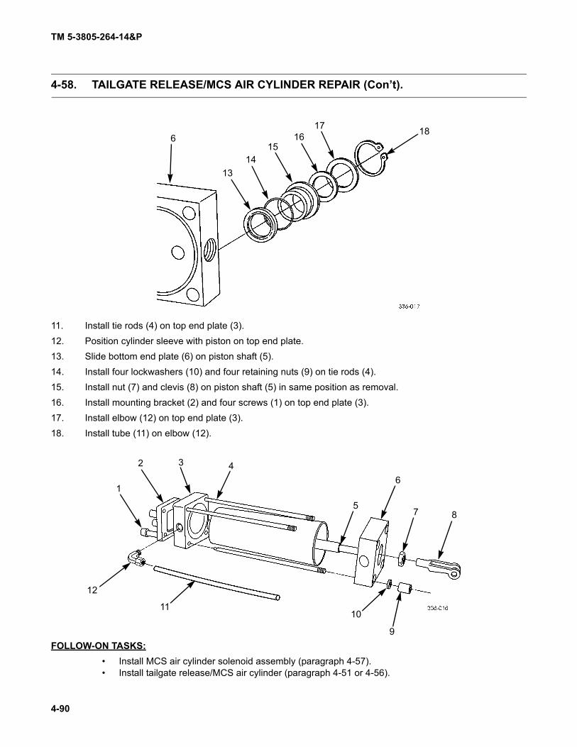
TM 5-3805-264-14&P
4-90
4-58. TAILGATE RELEASE/MCS AIR CYLINDER REPAIR (Con’t).
11. Install tie rods (4) on top end plate (3).12. Position cylinder sleeve with piston on top end plate.13. Slide bottom end plate (6) on piston shaft (5).14. Install four lockwashers (10) and four retaining nuts (9) on tie rods (4).15. Install nut (7) and clevis (8) on piston shaft (5) in same position as removal.16. Install mounting bracket (2) and four screws (1) on top end plate (3).17. Install elbow (12) on top end plate (3).18. Install tube (11) on elbow (12).
FOLLOW-ON TASKS:• Install MCS air cylinder solenoid assembly (paragraph 4-57).• Install tailgate release/MCS air cylinder (paragraph 4-51 or 4-56).
6
1314
1516
17 18
1
2 3 4
5
6
7 8
9
1011
12

TM 5-3805-264-14&P
4-91
4-59. TAILGATE RELEASE/MCS AIR LINES AND FITTINGS REPLACEMENT.
This task covers:a. Removalb. Cleaning and Inspection
c. Installation
Initial Setup:Equipment Conditions:
• Chassis air system drained (TM 9-2320-363-10or TM 9-2320-302-10).
• MCS air system drained (Chapter 2, Section II,Operator PMCS).
• MCS tailgate cover removed, if replacing MCSair lines (paragraph 4-53).
Tools/Test Equipment:• General mechanic's tool kit (Item 8, Appendix I)
Materials/Parts:• Marker tags (Item 20, Appendix F)• Tie wraps (Item 19, Appendix F)
General Safety Instructions:• DO NOT disconnect air lines while air system is
pressurized.
WARNING
DO NOT disconnect air lines while air system is pressurized. Air system pressuremust be released before air lines are disconnected. A line disconnected under pres-sure may cause personnel injury.
NOTE• Replacement of tailgate release or MCS air lines is the same. Replacement of an
MCS air line is shown.• Air lines should be tagged before removal (paragraph 4-17).• Note location of tie wraps prior to removal to aid in installation.
a. REMOVAL

TM 5-3805-264-14&P
4-92
4-59. TAILGATE RELEASE/MCS AIR LINES AND FITTINGS REPLACEMENT (Con’t).
1. If removing an air line, disconnect each end of air line (1) at fitting (2).
2. If removing a fitting, disconnect all air lines (1) from fitting (2).
Clean and inspect components in accordance with Chapter 4, Section III, General Maintenance Instruc-tions.
NOTE
For information on manufacturing air lines, refer to Appendix G, Illustrated List ofManufactured Items.
1. If installing a fitting, connect all air lines (1) to fitting (2).
2. If installing an air line, connect each end of air line (1) to fitting (2).
3. Install new tie wraps, as required.
FOLLOW-ON TASKS:
• Start engine and pressurize air systems (TM 9-2320-363-10 or TM 9-2320-302-10).• Operate tailgate release control valve lever or MCS gates (paragraph 2-1 or 2-13).
Check for leaks.• Install MCS tailgate cover, if removed (paragraph 4-53).
b. CLEANING AND INSPECTION
c. INSTALLATION
2
121
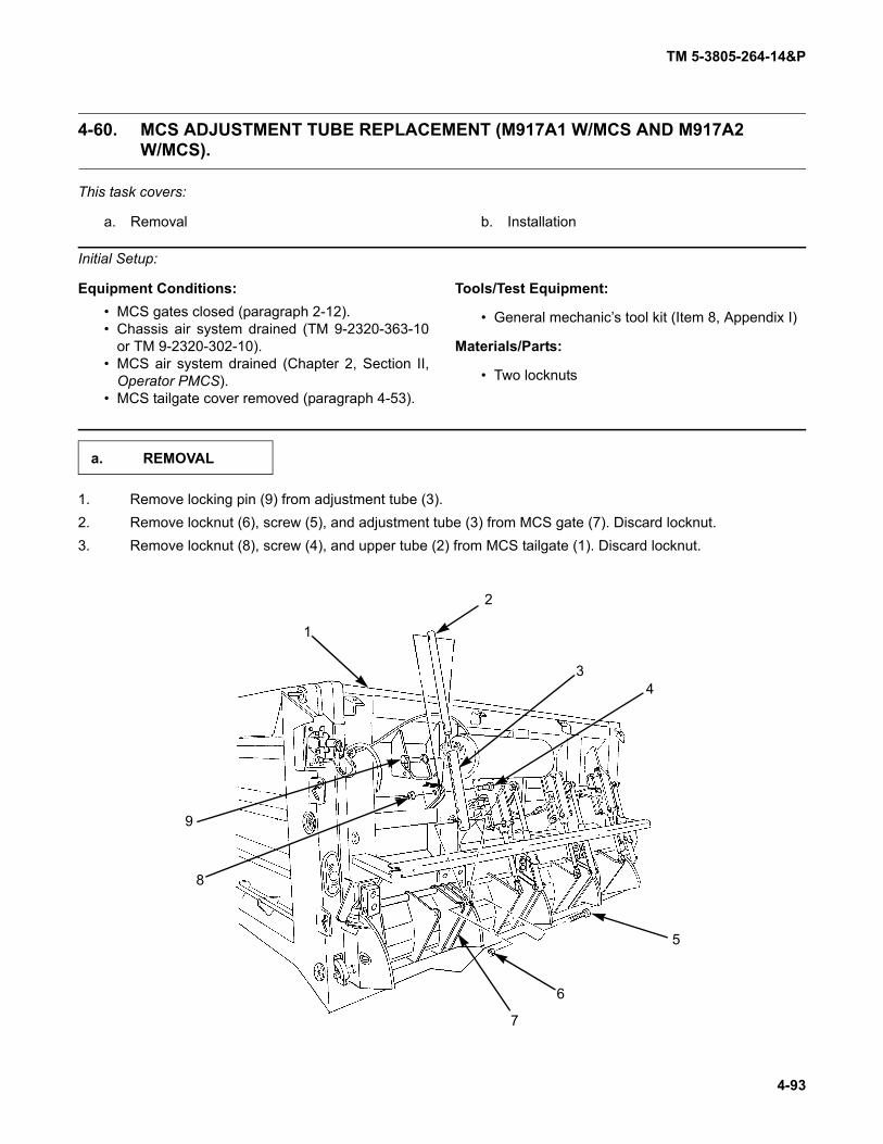
TM 5-3805-264-14&P
4-93
4-60. MCS ADJUSTMENT TUBE REPLACEMENT (M917A1 W/MCS AND M917A2W/MCS).
This task covers:
a. Removal b. Installation
Initial Setup:
Equipment Conditions:• MCS gates closed (paragraph 2-12).• Chassis air system drained (TM 9-2320-363-10
or TM 9-2320-302-10).• MCS air system drained (Chapter 2, Section II,
Operator PMCS).• MCS tailgate cover removed (paragraph 4-53).
Tools/Test Equipment:
• General mechanic’s tool kit (Item 8, Appendix I)
Materials/Parts:
• Two locknuts
1. Remove locking pin (9) from adjustment tube (3).2. Remove locknut (6), screw (5), and adjustment tube (3) from MCS gate (7). Discard locknut.3. Remove locknut (8), screw (4), and upper tube (2) from MCS tailgate (1). Discard locknut.
a. REMOVAL
7
6
5
43
2
1
9
8

TM 5-3805-264-14&P
4-94
4-60. MCS ADJUSTMENT TUBE REPLACEMENT (M917A1 W/MCS AND M917A2W/MCS) (Con’t).
1. Install upper tube (2) to MCS tailgate (1) with screw (4) and new locknut (8).
2. Position adjustment tube (3) over upper tube (2). Install adjustment tube to MCS gate (7) with screw (5)and new locknut (6).
CAUTION
Outer right and outer left side adjustment tube locking pins must be installed withpin heads to outside. If incorrectly installed, end of pins will protrude and becomebent.
3. Install locking pin (9) to adjustment tube (3).
FOLLOW-ON TASKS:
• Check operation of MCS adjustment tube (paragraph 2-12).• Install MCS tailgate cover (paragraph 4-53).
b. INSTALLATION
7
6
5
43
2
1
9
8

TM 5-3805-264-14&P
4-95
4-61. BODY PROP REPLACEMENT.
This task covers:
a. Removal b. Installation
Initial Setup:
Tools/Test Equipment:• General mechanic's tool kit (Item 8, Appendix I)
Materials/Parts:• One spring pin• Three lockwashers
1. Remove spring pin (5) and body prop (4) from pivot bracket (3). Discard spring pin.2. Remove two nuts (6), lockwashers (7), screws (2), and pivot bracket (3) from frame (11). Discard lock-
washers.3. Remove nut (8), lockwasher (9), screw (1), and support bracket (10) from frame (11). Discard lockwasher.
1. Install support bracket (10) to frame (11) with screw (1), new lockwasher (9), and nut (8).2. Install pivot bracket (3) to frame (11) with two screws (2), new lockwashers (7), and nuts (6).3. With body prop (4) positioned above support bracket (10), install body prop to pivot bracket (3) with new
spring pin (5).FOLLOW-ON TASKS:
• Lubricate body prop (Chapter 3, Section I).
a. REMOVAL
11 10 98 7 6
5
4
3
21
b. INSTALLATION

TM 5-3805-264-14&P
4-96
4-62. CAB SHIELD REPLACEMENT.
This task covers:
a. Removal
b. Cleaning and Inspection
c. Installation
Initial Setup:
Equipment Conditions:
• Beacon warning light removed (TM 9-2320-363-10 or TM 9-2320-302-10).
• Dump body raised and supported on body props(paragraph 2-15).
• Beacon warning light wiring harness removedfrom cab shield (paragraph 4-45).
Materials/Parts:• Fourteen locknuts
Tools/Test Equipment:• General mechanic's tool kit (Item 8, Appendix I)• Lifting slings (three) (Item 6, Appendix I)• Torque wrench (Item 11, Appendix I)• Suitable lifting device
1. At center of cab shield (1), remove six locknuts (9), 12 washers (8), and six screws (7). Discard locknuts.
2. Remove body props and lower dump body (paragraph 2-15).
a. REMOVAL
1
2
3
4
4
56
7
8
8
9

TM 5-3805-264-14&P
4-97
4-62. CAB SHIELD REPLACEMENT (Con’t).
WARNING
Use extreme care when handling heavy parts. Lifting cables, chains, hooks, andslings must be in good condition and of suitable capacity. Keep clear of parts sup-ported only by lifting device. Failure to follow this warning may result in death orinjury to personnel and damage to equipment.
3. Attach lifting slings (2) to cab shield (1) and remove slack from lifting slings.
4. Remove six locknuts (9), 12 washers (8), and six screws (7) from outside edges of cab shield (1) and dumpbody (6). Discard locknuts.
5. Remove two locknuts (5), four washers (4), and two screws (3) from top of cab shield (1) and dump body(6). Discard locknuts.
6. Lift cab shield (1) from dump body (6) and place cab shield in a safe work area.
Clean and inspect components in accordance with Chapter 4, Section III, General Maintenance Instruc-tions.
WARNING
Use extreme care when handling heavy parts. Lifting cables, chains, hooks, andslings must be in good condition and of suitable capacity. Keep clear of parts sup-ported only by lifting device. Failure to follow this warning may result in death orinjury to personnel and damage to equipment.
1. Raise cab shield (1) to dump body (6).
2. Install two screws (3), four washers (4), and two new locknuts (5) to top of cab shield (1) and dump body(6).
3. Install six screws (7), 12 washers (8), and six new locknuts (9) to outside edges of cab shield (1) and dumpbody (6).
4. Remove lifting slings (2) from cab shield (1).
5. Raise and support dump body on body props (paragraph 2-15).
6. Install six screws (7), 12 washers (8), and six new locknuts (9) to center of cab shield (1) and dump body(6).
b. CLEANING AND INSPECTION
c. INSTALLATION

TM 5-3805-264-14&P
4-98
4-62. CAB SHIELD REPLACEMENT (Con’t).
7. Torque 12 locknuts (9) and two locknuts (5) to 150 ft.-lb. (203 N•m).
FOLLOW-ON TASKS:• Install beacon warning light wiring harness to cab shield (paragraph 4-45).• Remove body props and lower dump body (paragraph 2-15).• Install beacon warning light (TM 9-2320-363-10 or TM 9-2320-302-10).
59

TM 5-3805-264-14&P
4-99
4-63. MUD FLAP REPLACEMENT.
This task covers:a. Removal b. Installation
Initial Setup:Tools/Test Equipment:
• General mechanic's tool kit (Item 8, Appendix I)Materials/Parts:
• Two spring pins• Six locknuts
1. Remove four locknuts (8), screws (6), plate (5), and mud flap (7) from mounting plate (4). Discard locknuts.2. Remove two spring pins (2), washers (3), and shaft (9) and separate mounting plate (4) from weldment (1)
on dump body. Discard spring pins.
a. REMOVAL
2
3 9
8
76
5
43
2
1

TM 5-3805-264-14&P
4-100
4-63. MUD FLAP REPLACEMENT (Con’t).
3. Remove two locknuts (13), screws (11), anchorplate (12), and mounting plate (10) from mudflap (7). Discard locknuts.
1. Install mounting plate (10) and anchor plate (12) to mud flap (7) with two screws (11) and new locknuts(13).
2. Install mounting plate (4) to weldment (1) on dump body with shaft (9), two washers (3), and new springpins (2) through shaft.
3. Install mud flap (7) and plate (5) to mounting plate (4) with four screws (6) and new locknuts (8).
7
10
13
12
11
b. INSTALLATION
2
3 9
8
76
5
43
2
1

TM 5-3805-264-14&P
4-101
Section VIII. DUMP BODY ACCESSORY ITEMS MAINTENANCE
Paragraph PageNumber Paragraph Title Number
4-64. Cargo Cover Replacement . . . . . . . . . . . . . . . . . . . . . . . . . . . . . . . . . . . . . . . . . . . . . . . . . . 4-1014-65. Cargo Cover Crank Assembly Maintenance . . . . . . . . . . . . . . . . . . . . . . . . . . . . . . . . . . . . 4-1034-66. Cargo Cover Chain and Sprockets Replacement . . . . . . . . . . . . . . . . . . . . . . . . . . . . . . . . . 4-1064-67. Cargo Cover Support Frame and Roll-Up Bar Replacement . . . . . . . . . . . . . . . . . . . . . . . . 4-1104-68. Reflector Replacement . . . . . . . . . . . . . . . . . . . . . . . . . . . . . . . . . . . . . . . . . . . . . . . . . . . . . 4-1134-69. Data Plate Replacement. . . . . . . . . . . . . . . . . . . . . . . . . . . . . . . . . . . . . . . . . . . . . . . . . . . . 4-1144-70. Shovel Bracket Replacement . . . . . . . . . . . . . . . . . . . . . . . . . . . . . . . . . . . . . . . . . . . . . . . . 4-1154-71. Spill Shield Replacement . . . . . . . . . . . . . . . . . . . . . . . . . . . . . . . . . . . . . . . . . . . . . . . . . . . 4-116
4-64. CARGO COVER REPLACEMENT.
This task covers:
a. Removal b. Installation
Initial Setup:
Tools/Test Equipment:• General mechanic’s tool kit (Item 8, Appendix I)
Materials/Parts:• Two locknuts
1. Extend cargo cover (2) over dump body (paragraph 2-14). Release control handle and manually unwindcargo cover to access screws (3).
2. Remove six screws (3) holding cargo cover (2) to roll-up bar (1).
a. REMOVAL
1
3
2

TM 5-3805-264-14&P
4-102
4-64. CARGO COVER REPLACEMENT (Con’t).
3. Uncrimp and remove centering springs (7) from eye bolts (8) and from grommets in cargo cover (2).4. Remove two locknuts (5) and eye bolts (8) from cross arm (6) and connecting arms (4). Discard locknuts.5. Remove cross arm (6) from connecting arms (4). Slide cross arm from cargo cover (2). Remove cargo
cover.
1. Install cross arm (6) through pocket in cargo cover (2).2. Install cross arm (6) into each connecting arm (4) and secure with two eye bolts (8) and new locknuts (5).3. Attach two centering springs (7) to eye bolts (8) and to grommets in cargo cover (2). Crimp spring ends.
4. Pull cargo cover (2) to roll-up bar (1). Passcover UNDER roll-up bar and secure to roll-upbar with six screws (3).
5. Fully retract cargo cover (2) (paragraph 2-14).
b. INSTALLATION
45
2 6
7
8
2
3
1
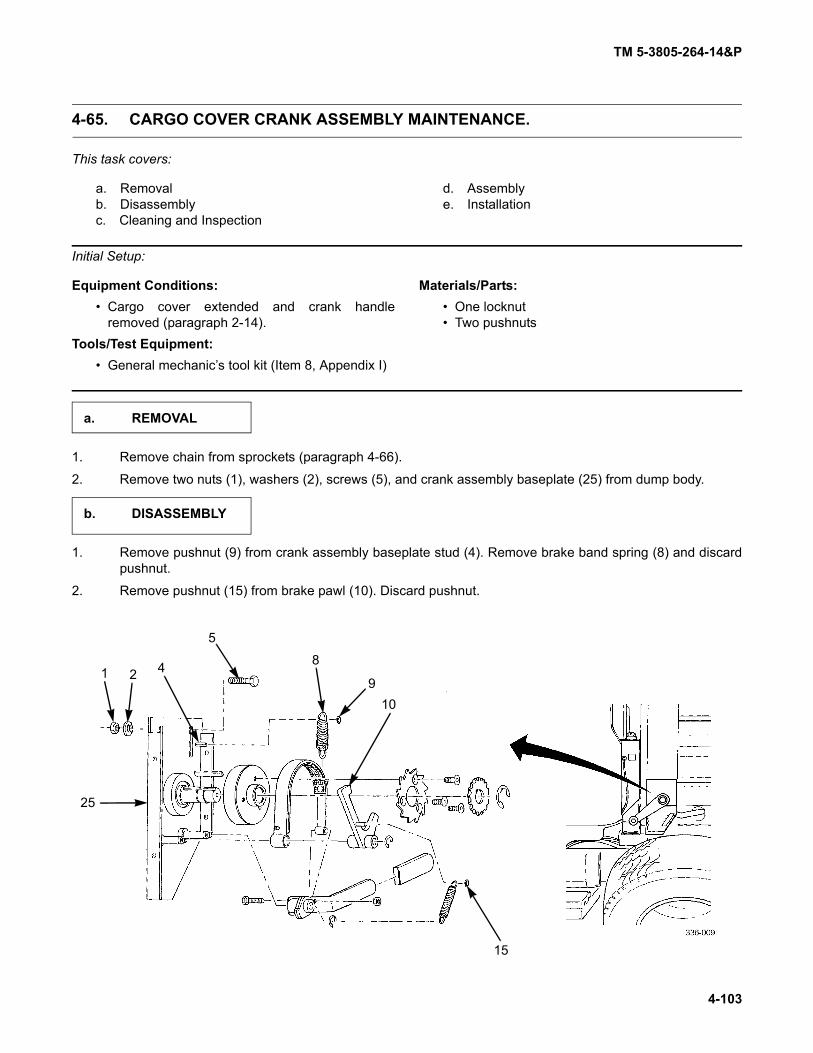
TM 5-3805-264-14&P
4-103
4-65. CARGO COVER CRANK ASSEMBLY MAINTENANCE.
This task covers:
a. Removalb. Disassemblyc. Cleaning and Inspection
d. Assemblye. Installation
Initial Setup:
Equipment Conditions:• Cargo cover extended and crank handle
removed (paragraph 2-14).Tools/Test Equipment:
• General mechanic’s tool kit (Item 8, Appendix I)
Materials/Parts:• One locknut• Two pushnuts
1. Remove chain from sprockets (paragraph 4-66).
2. Remove two nuts (1), washers (2), screws (5), and crank assembly baseplate (25) from dump body.
1. Remove pushnut (9) from crank assembly baseplate stud (4). Remove brake band spring (8) and discardpushnut.
2. Remove pushnut (15) from brake pawl (10). Discard pushnut.
a. REMOVAL
b. DISASSEMBLY
4
5
8
910
1 2
15
25

TM 5-3805-264-14&P
4-104
4-65. CARGO COVER CRANK ASSEMBLY MAINTENANCE (Con’t).
3. Remove retaining ring (20) from control handle (21). Remove brake pawl spring (16). Discard retaining ringif damaged.
4. Remove retaining ring (18) and brake pawl (10) from pivot shaft (23). Discard retaining ring if damaged.
5. Remove control handle (21) and brake band (7) from crank assembly baseplate (25). Remove locknut (19)and screw (22) from control handle and brake band. Discard locknut. Replace handle grip (17) if damaged.
6. Remove retaining ring (14) from crank shaft (24). Remove chain sprocket (13) from shaft. Discard retainingring if damaged.
7. Remove three screws (12) and ratchet (11) from brake drum (6).
8. Remove brake drum (6) and key (3) from crank shaft (24).
Clean and inspect all components in accordance with Chapter 4, Section III, General MaintenanceInstructions.
1 23
4
5
6 7
8 9
10
11
12 13 14
15
16
171819
202122
2324
25
c. CLEANING AND INSPECTION

TM 5-3805-264-14&P
4-105
4-65. CARGO COVER CRANK ASSEMBLY MAINTENANCE (Con’t).
1. Install key (3) and brake drum (6) on crank shaft (24).2. Position ratchet (11) on brake drum (6) and secure with three screws (12).3. Install chain sprocket (13) on crank shaft (24) with retaining ring (14).4. Attach brake band (7) to control handle (21) with screw (22) and new locknut (19).5. Position brake band (7) over brake drum (6). Position control handle (21) on pivot shaft (23). 6. Install brake pawl (10) on crank assembly baseplate (25) with retaining ring (18).7. Install brake pawl spring (16) between control handle (21) and brake pawl (10). Secure brake pawl spring
to pawl with new pushnut (15). Secure to control handle with retaining ring (20).8. Install brake band spring (8) between brake band (7) and crank assembly baseplate stud (4). Secure with
new pushnut (9).
1. Install crank assembly baseplate (25) on dump body with two screws (5), washers (2), and nuts (1). Do nottighten screws.
2. Install chain to sprockets and tighten screws (5) (paragraph 4-66).
FOLLOW-ON TASKS:• Check operation of cargo cover (paragraph 2-14).• Fully retract cargo cover (paragraph 2-14).
d. ASSEMBLY
e. INSTALLATION
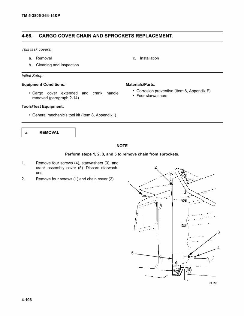
TM 5-3805-264-14&P
4-106
4-66. CARGO COVER CHAIN AND SPROCKETS REPLACEMENT.
This task covers:
a. Removal
b. Cleaning and Inspection
c. Installation
Initial Setup:
Equipment Conditions:
• Cargo cover extended and crank handleremoved (paragraph 2-14).
Tools/Test Equipment:
• General mechanic’s tool kit (Item 8, Appendix I)
Materials/Parts:• Corrosion preventive (Item 8, Appendix F)• Four starwashers
NOTE
Perform steps 1, 2, 3, and 5 to remove chain from sprockets.
1. Remove four screws (4), starwashers (3), andcrank assembly cover (5). Discard starwash-ers.
2. Remove four screws (1) and chain cover (2).
a. REMOVAL
1
2
3
45

TM 5-3805-264-14&P
4-107
4-66. CARGO COVER CHAIN AND SPROCKETS REPLACEMENT (Con’t).
3. Loosen crank assembly baseplate mountingscrews (6). Raise crank assembly baseplate(11) and remove chain (7) from sprocket (10).
4. Remove retaining ring (9) and sprocket (10)from crankshaft (8). Discard retaining ring ifdamaged.
5. Remove chain (7) from sprocket (16).6. Loosen set screw (15) and remove sprocket
(16) with sprocket alinement key (12) from roll-up bar (14).
Clean and inspect all components in accordance with Chapter 4, Section III, General MaintenanceInstructions.
67
8
9
10
11
7
12
14
1516
b. CLEANING AND INSPECTION

TM 5-3805-264-14&P
4-108
4-66. CARGO COVER CHAIN AND SPROCKETS REPLACEMENT (Con’t).
1. Install sprocket alinement key (12) andsprocket (16) on roll-up bar (14). Tighten setscrew (15).
2. Position chain (7) over sprocket (16).
3. Install sprocket (10) on crankshaft (8) withretaining ring (9).
4. Raise baseplate (11) and position chain (7)under sprocket (10). Lower baseplate to puttension on chain. Tighten mounting screws (6).
5. Apply corrosion preventive sparingly to chain(7) and to roller shaft bearings (13) on bothends of roll-up bar (14).
c. INSTALLATION
7
12
14
1516
13
67
8
9
10
11

TM 5-3805-264-14&P
4-109
4-66. CARGO COVER CHAIN AND SPROCKETS REPLACEMENT (Con’t).
6. Install chain cover (2) with four screws (1).7. Install crank assembly cover (5) with four new
starwashers (3) and screws (4).
FOLLOW-ON TASKS:• Check operation of cargo cover (paragraph 2-14).• Fully retract cargo cover (paragraph 2-14).
1
2
3
45

TM 5-3805-264-14&P
4-110
4-67. CARGO COVER SUPPORT FRAME AND ROLL-UP BAR REPLACEMENT.
This task covers:
a. Removalb. Cleaning and Inspection
c. Installation
Initial Setup:
Equipment Conditions:• Cargo cover removed (paragraph 4-64).• Cargo cover chain removed (paragraph 4-66).
Tools/Test Equipment:• General mechanic’s tool kit (Item 8, Appendix I)
Materials/Parts:• One locknut• One spring pin• Five lockwashers
NOTELeft and right side components of cargo cover support frame are removed andinstalled the same way; left side is illustrated.
1. Remove rubber strap from connecting arm (3) and swing arm (5).2. Remove spring pin (11) from shaft (6) on spring assembly (7). Remove swing arm (5) from shaft. Discard
spring pin.3. Remove nut (2) and eyebolt (4) and separate swing arm (5) and connecting arm (3). Discard locknut.4. Remove two nuts (10), lockwashers (9), and screws (8) from spring assembly (7). Remove spring assem-
bly from dump body and from welded shaft support bar and tube (1). Discard lockwashers.
a. REMOVAL
1
2
11
3
4
567
8
9
10
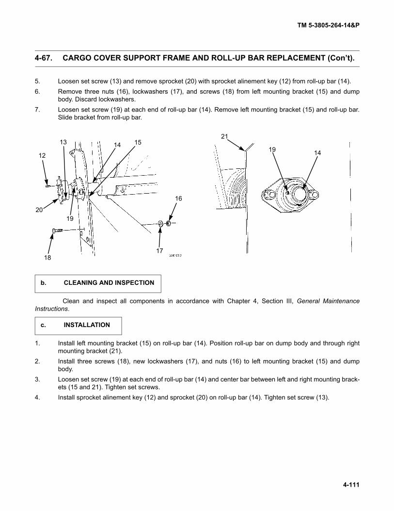
TM 5-3805-264-14&P
4-111
4-67. CARGO COVER SUPPORT FRAME AND ROLL-UP BAR REPLACEMENT (Con’t).
5. Loosen set screw (13) and remove sprocket (20) with sprocket alinement key (12) from roll-up bar (14).6. Remove three nuts (16), lockwashers (17), and screws (18) from left mounting bracket (15) and dump
body. Discard lockwashers.7. Loosen set screw (19) at each end of roll-up bar (14). Remove left mounting bracket (15) and roll-up bar.
Slide bracket from roll-up bar.
Clean and inspect all components in accordance with Chapter 4, Section III, General MaintenanceInstructions.
1. Install left mounting bracket (15) on roll-up bar (14). Position roll-up bar on dump body and through rightmounting bracket (21).
2. Install three screws (18), new lockwashers (17), and nuts (16) to left mounting bracket (15) and dumpbody.
3. Loosen set screw (19) at each end of roll-up bar (14) and center bar between left and right mounting brack-ets (15 and 21). Tighten set screws.
4. Install sprocket alinement key (12) and sprocket (20) on roll-up bar (14). Tighten set screw (13).
2019
18
12
17
16
151413
1419
21
b. CLEANING AND INSPECTION
c. INSTALLATION

TM 5-3805-264-14&P
4-112
4-67. CARGO COVER SUPPORT FRAME AND ROLL-UP BAR REPLACEMENT (Con’t).
5. Install spring assembly (7) on dump body and through welded shaft support bar and tube (1) with twoscrews (8), new lockwashers (9), and nuts (10).
6. Connect swing arm (5) and connecting arm (3) with eyebolt (4) and nut (2).7. Install swing arm (5) on spring assembly shaft (6). Install new spring pin (11) through shaft.8. Install one end of rubber strap on connecting arm (3) eyebolt and opposite end on swing arm (5) eyebolt.
FOLLOW-ON TASKS:• Install cargo cover chain (paragraph 4-66).• Install cargo cover (paragraph 4-64).• Check operation of cargo cover (paragraph 2-14).• Fully retract cargo cover (paragraph 2-14).
1
2
11
3
4
567
8
9
10

TM 5-3805-264-14&P
4-113
4-68. REFLECTOR REPLACEMENT.
This task covers:a. Removal b. Cleaning
Initial Setup:Tools/Test Equipment:
• General mechanic’s tool kit (Item 8, Appendix I)
Remove reflector (1) from dump body or tailgate.
Clean reflector mounting surface in accordance with Chapter 4, Section III, General Maintenance Instruc-tions.
Remove backing paper from reflector (1). Install reflector on dump body or tailgate.
a. REMOVAL
1
b. CLEANING
c. INSTALLATION

TM 5-3805-264-14&P
4-114
4-69. DATA PLATE REPLACEMENT.
This task covers:a. Removal b. Installation
Initial Setup:Tools/Test Equipment:
• General mechanic’s tool kit (Item 8, Appendix I)Materials/Parts:
• Four drive screws
Remove four drive screws (2) and data plate (1) from dump body. Discard drive screws.
Install data plate (1) on dump body with four new drive screws (2).
a. REMOVAL
21
b. INSTALLATION
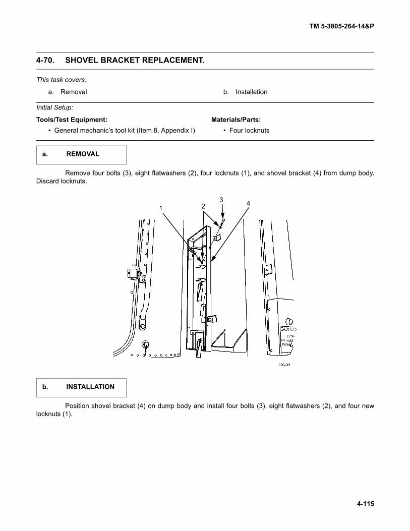
TM 5-3805-264-14&P
4-115
4-70. SHOVEL BRACKET REPLACEMENT.
This task covers:
a. Removal b. Installation
Initial Setup:
Tools/Test Equipment:• General mechanic’s tool kit (Item 8, Appendix I)
Materials/Parts:• Four locknuts
Remove four bolts (3), eight flatwashers (2), four locknuts (1), and shovel bracket (4) from dump body.Discard locknuts.
Position shovel bracket (4) on dump body and install four bolts (3), eight flatwashers (2), and four newlocknuts (1).
a. REMOVAL
2143
b. INSTALLATION

TM 5-3805-264-14&P
4-116
4-71. SPILL SHIELD REPLACEMENT.
This task covers:
a. Removal b. Installation
Initial Setup:
Tools/Test Equipment:• General mechanic’s tool kit (Item 8, Appendix I)
Materials/Parts:• Eight locknuts
Personnel Required: Two
1. Remove locknut (4), washer (3), bolt (1), and tab (2) from spill shield (7). Discard locknut.2. Repeat step 1 for opposite side.3. Remove six locknuts (5), six washers (6), six bolts (8), and spill shield (7). Discard locknuts.
1. Position spill shield (7) on dump body and install six bolts (8), six washers (6), and six new locknuts (5).2. Position tab (2) on spill shield (7) and install bolt (1), washer (3), and new locknut (4).3. Repeat step 2 for opposite side.
a. REMOVAL
2
1
53
6
78
4
371-207
b. INSTALLATION
TM 5-3805-264-14&P
4-117
Section IX. HYDRAULIC SYSTEM MAINTENANCE
Paragraph PageNumber Paragraph Title Number
4-72. Hydraulic Control Lever Replacement . . . . . . . . . . . . . . . . . . . . . . . . . . . . . . . . . . . . . . . . . 4-1174-73. Hydraulic Control Lever Cable Replacement . . . . . . . . . . . . . . . . . . . . . . . . . . . . . . . . . . . . 4-1274-74. Hydraulic Hoses and Fittings Replacement . . . . . . . . . . . . . . . . . . . . . . . . . . . . . . . . . . . . . 4-1364-75. Hydraulic Reservoir Replacement . . . . . . . . . . . . . . . . . . . . . . . . . . . . . . . . . . . . . . . . . . . . 4-1404-76. Hydraulic Reservoir Repair. . . . . . . . . . . . . . . . . . . . . . . . . . . . . . . . . . . . . . . . . . . . . . . . . . 4-1434-77. Hydraulic Oil Filter Element Replacement . . . . . . . . . . . . . . . . . . . . . . . . . . . . . . . . . . . . . . 4-1454-78. Hydraulic Oil Filter Service Indicator Gage Replacement . . . . . . . . . . . . . . . . . . . . . . . . . . 4-147
4-72. HYDRAULIC CONTROL LEVER REPLACEMENT.
This task covers:a. Removal b. Installation
Initial Setup:Equipment Conditions:
• CTIS electronic control unit (ECU) removed (TM9-2320-363-20 or TM 9-2320-302-20).
• MCS control unit removed (M917A1 w/MCS)(paragraph 4-42).
Tools/Test Equipment:• General mechanic's tool kit (Item 8, Appendix I).
Materials/Parts:
• Marker tags (Item 20, Appendix F)• Six lockwashers
References:• TM 9-2320-363-10• TM 9-2320-302-10
NOTEAlthough slightly different in shape, M917A1 and M917A2 shift towers are similar.M917A1 shift tower is illustrated. Perform only those steps that apply to your model.
NOTEWires and cables should be tagged before removal (paragraph 4-17).
a. REMOVAL

TM 5-3805-264-14&P
4-118
4-72. HYDRAULIC CONTROL LEVER REPLACEMENT (Con’t).
1. Remove six screws (2) and rear access panel(3) from shift tower (1).
2. Repeat step 1 for front access panel.
3. To keep shift tower (1) rigid, reinstall two topand two bottom screws (2) on front and rear ofshift tower (1).
4. Disconnect six connectors (4) from shift towerjumper harness connectors.
12
3
2
22
1
4
4
4

TM 5-3805-264-14&P
4-119
4-72. HYDRAULIC CONTROL LEVER REPLACEMENT (Con’t).
NOTETo ease installation, note mounting position of cable pivot pins and hold-downclamps prior to disconnecting cables.
5. Place transmission selector lever in D (Drive) position (TM 9-2320-363-10 or TM 9-2320-302-10)).6. Tag transmission shift cable (7).7. Remove two nuts (12), lockwashers (11), screws (8), clamp (10), and spacer (9) from bracket (13). Discard
lockwashers.8. Remove retaining pin (5) from pivot pin (6) and pivot pin from bracket (14).
56
7
89
1011
12
13
14
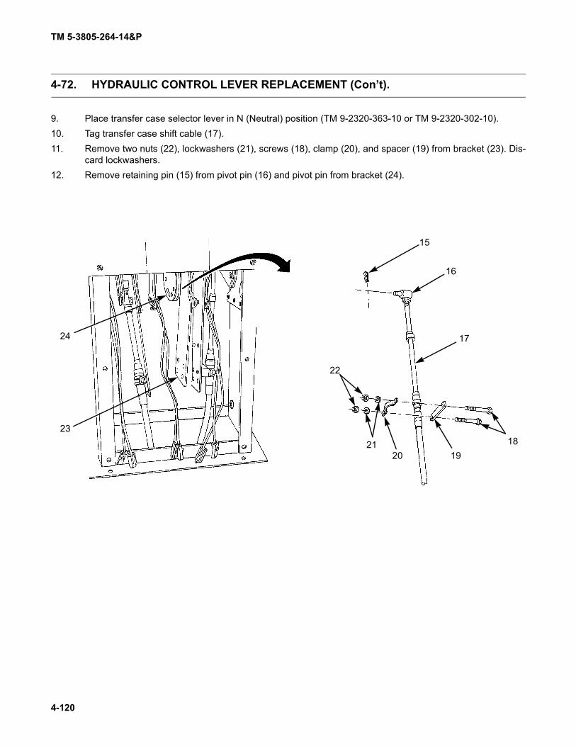
TM 5-3805-264-14&P
4-120
4-72. HYDRAULIC CONTROL LEVER REPLACEMENT (Con’t).
9. Place transfer case selector lever in N (Neutral) position (TM 9-2320-363-10 or TM 9-2320-302-10).10. Tag transfer case shift cable (17).11. Remove two nuts (22), lockwashers (21), screws (18), clamp (20), and spacer (19) from bracket (23). Dis-
card lockwashers.12. Remove retaining pin (15) from pivot pin (16) and pivot pin from bracket (24).
15
16
17
181920
21
22
23
24
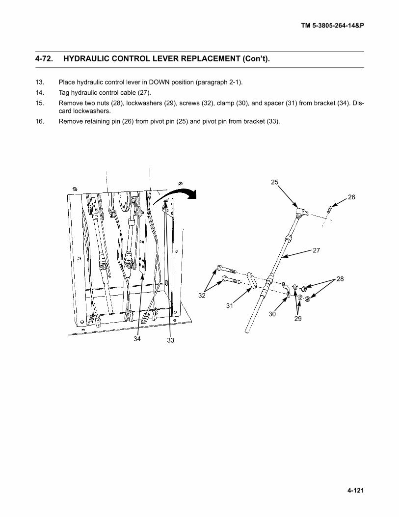
TM 5-3805-264-14&P
4-121
4-72. HYDRAULIC CONTROL LEVER REPLACEMENT (Con’t).
13. Place hydraulic control lever in DOWN position (paragraph 2-1).14. Tag hydraulic control cable (27).15. Remove two nuts (28), lockwashers (29), screws (32), clamp (30), and spacer (31) from bracket (34). Dis-
card lockwashers.16. Remove retaining pin (26) from pivot pin (25) and pivot pin from bracket (33).
34 33
3231
3029
28
27
26
25

TM 5-3805-264-14&P
4-122
4-72. HYDRAULIC CONTROL LEVER REPLACEMENT (Con’t).
17. Remove two top screws (2) from front and rearof shift tower (1).
18. Lift handle assemblies (35) from shift tower (1).
19. Separate hydraulic control lever (37) fromtransfer case selector lever (38) by removingtwo bolts (36), flatwashers (40), and nuts (39).
35
2
1
36
37
40
39
38
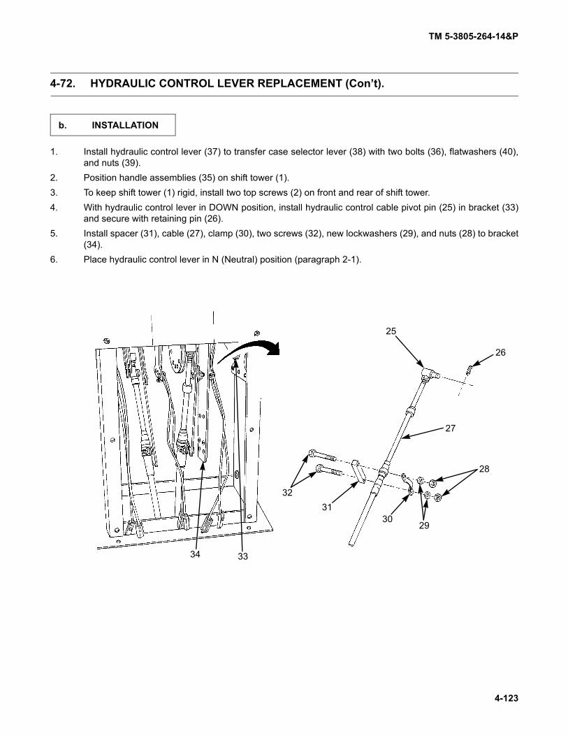
TM 5-3805-264-14&P
4-123
4-72. HYDRAULIC CONTROL LEVER REPLACEMENT (Con’t).
1. Install hydraulic control lever (37) to transfer case selector lever (38) with two bolts (36), flatwashers (40),and nuts (39).
2. Position handle assemblies (35) on shift tower (1).3. To keep shift tower (1) rigid, install two top screws (2) on front and rear of shift tower.4. With hydraulic control lever in DOWN position, install hydraulic control cable pivot pin (25) in bracket (33)
and secure with retaining pin (26).5. Install spacer (31), cable (27), clamp (30), two screws (32), new lockwashers (29), and nuts (28) to bracket
(34).6. Place hydraulic control lever in N (Neutral) position (paragraph 2-1).
b. INSTALLATION
34 33
3231
3029
28
27
26
25

TM 5-3805-264-14&P
4-124
4-72. HYDRAULIC CONTROL LEVER REPLACEMENT (Con’t).
7. Install transfer case control cable pivot pin (16) in bracket (24) and secure with retaining pin (15).8. Install spacer (19), cable (17), clamp (20), two screws (18), new lockwashers (21), and nuts (22) to bracket
(23).
9. With transmission selector lever in D (Drive) position, install transmission control cable pivot pin (6) inbracket (14) and secure with retaining pin (5).
10. Install spacer (9), cable (7), clamp (10), two screws (8), new lockwashers (11), and nuts (12) to bracket(13).
15
16
17
181920
21
22
23
24
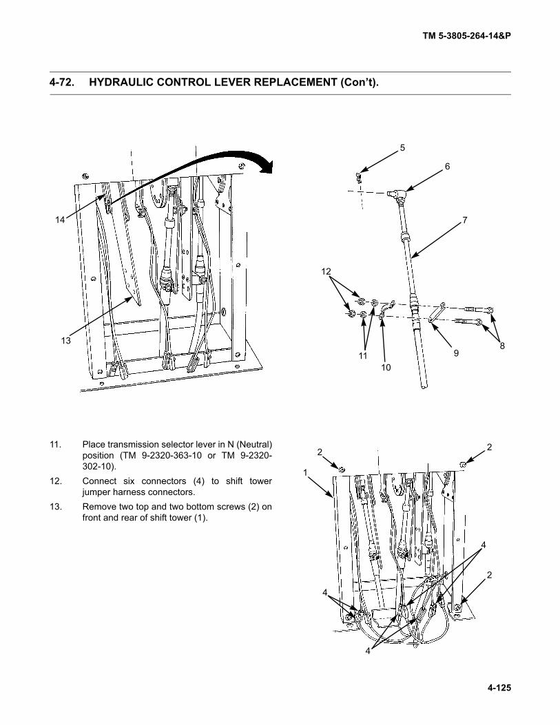
TM 5-3805-264-14&P
4-125
4-72. HYDRAULIC CONTROL LEVER REPLACEMENT (Con’t).
11. Place transmission selector lever in N (Neutral)position (TM 9-2320-363-10 or TM 9-2320-302-10).
12. Connect six connectors (4) to shift towerjumper harness connectors.
13. Remove two top and two bottom screws (2) onfront and rear of shift tower (1).
5
6
7
89
1011
12
13
14
2
22
1
4
4
4

TM 5-3805-264-14&P
4-126
4-72. HYDRAULIC CONTROL LEVER REPLACEMENT (Con’t).
14. Install rear access panel (3) and six screws (2).15. Repeat step 14 for front access panel.
FOLLOW-ON TASKS:• Install MCS control unit (M917A1 w/MCS) (paragraph 4-42).• Install CTIS electronic control unit (ECU) (TM 9-2320-363-20 or TM 9-2320-302-20).
12
3

TM 5-3805-264-14&P
4-127
4-73. HYDRAULIC CONTROL LEVER CABLE REPLACEMENT.
This task covers:
a. Removal b. Installation
Initial Setup:
Equipment Conditions:
• Wheels blocked (TM 9-2320-363-10 or TM 9-2320-302-10).
• CTIS electronic control unit (ECU) removed (TM9-2320-363-20 or TM 9-2320-302-20).
• MCS control unit removed (M917A1 w/MCS)(paragraph 4-42).
Tools/Test Equipment:
• General mechanic’s tool kit (Item 8, Appendix I)
Materials/Parts:
• Marker tags (Item 20, Appendix F)• One cotter pin• Eight lockwashers
References:
• TM 9-2320-363-10• TM 9-2320-302-10• TM 9-2320-363-20• TM 9-2320-302-20
NOTE
Although slighty different in shape, M917A1 and M917A2 shift towers are similar.M917A1 shift tower is shown. Perform only those steps that apply to your model.
1. Remove six screws (2) and rear access panel(3) from shift tower (1).
2. Repeat step 1 to remove front access panelfrom shift tower.
3. To keep shift tower rigid, reinstall two top andtwo bottom screws (2) on front and rear of shifttower (1).
a. REMOVAL
12
3
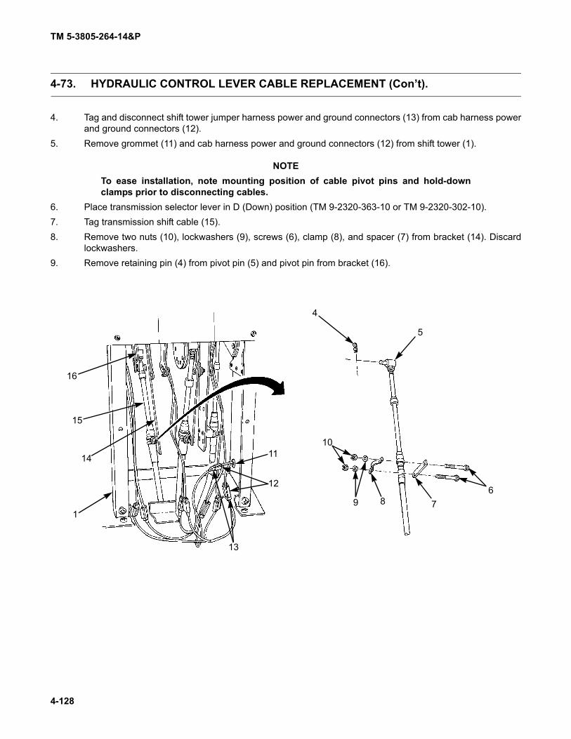
TM 5-3805-264-14&P
4-128
4-73. HYDRAULIC CONTROL LEVER CABLE REPLACEMENT (Con’t).
4. Tag and disconnect shift tower jumper harness power and ground connectors (13) from cab harness powerand ground connectors (12).
5. Remove grommet (11) and cab harness power and ground connectors (12) from shift tower (1).
NOTETo ease installation, note mounting position of cable pivot pins and hold-downclamps prior to disconnecting cables.
6. Place transmission selector lever in D (Down) position (TM 9-2320-363-10 or TM 9-2320-302-10).7. Tag transmission shift cable (15).8. Remove two nuts (10), lockwashers (9), screws (6), clamp (8), and spacer (7) from bracket (14). Discard
lockwashers.9. Remove retaining pin (4) from pivot pin (5) and pivot pin from bracket (16).
4
5
6789
1011
12
13
1
14
15
16

TM 5-3805-264-14&P
4-129
4-73. HYDRAULIC CONTROL LEVER CABLE REPLACEMENT (Con’t).
10. Place transfer case selector lever in N (Neutral) position (TM 9-2320-363-10 or TM 9-2320-302-10).11. Tag transfer case shift cable (25).12. Remove two nuts (23), lockwashers (22), screws (19), clamp (21), and spacer (20) from bracket (24). Dis-
card lockwashers.13. Remove retaining pin (17) from pivot pin (18) and pivot pin from bracket (26).
26
25
24
17
18
19
20
2122
23

TM 5-3805-264-14&P
4-130
4-73. HYDRAULIC CONTROL LEVER CABLE REPLACEMENT (Con’t).
14. Place hydraulic control lever in DOWN position (paragraph 2-1).15. Tag hydraulic control lever cable (36).16. Remove two nuts (31), lockwashers (30), screws (34), clamp (32), and spacer (33) from bracket (35). Dis-
card lockwashers.17. Remove retaining pin (29) from pivot pin (28) and pivot pin from bracket (27).
27
2829
31
30
33
32
3435
36

TM 5-3805-264-14&P
4-131
4-73. HYDRAULIC CONTROL LEVER CABLE REPLACEMENT (Con’t).
18. Remove four screws (37) and shift tower (1)from cab floor.
19. Remove transmission tunnel access cover (TM9-2320-363-20 or TM 9-2320-302-20).
20. At hydraulic pump, turn jam nut (38) over entire length of threads on cable (36).21. Remove two screws (40), flatwashers (42), and lockwashers (41) from flange clamp (43). Discard lock-
washers.22. Slide flange clamp (43) away from bonnet (39).23. Unscrew bonnet (39) and slide spacer (44) along cable (36) until cable bracket (46) can be accessed.24. Remove cotter pin (47) and clevis pin (45) from hydraulic pump actuator (48). Discard cotter pin.
1
37
36 38 39
40 41 42 43 44 4546 47
48

TM 5-3805-264-14&P
4-132
4-73. HYDRAULIC CONTROL LEVER CABLE REPLACEMENT (Con’t).
25. Remove nut (49) and cable bracket (46).26. Count number of threads from end of cable (36) to nut (50).27. Remove nut (50).
1. Install nut (50) onto cable (36) same number of threads as removal.2. Slide cable bracket (46) onto cable (36) and install nut (49).3. Position cable bracket (46) onto hydraulic pump actuator (48) and install clevis pin (45) and new cotter pin
(47).4. Slide spacer (44), screw bonnet (39), and slide flange clamp (43) over cable bracket (46).5. Install two screws (40), flatwashers (42), and new lockwashers (41) to flange clamp (43).6. Slide jam nut (38) onto cable (36).7. Tighten jam nut (38) against flange clamp (43).8. Install transmission tunnel access cover (TM 9-2320-363-20 or TM 9-2320-302-20).
9. Install four screws (37) securing shift tower (1)to cab floor.
b. INSTALLATION
36 38 39
40 41 42 43 44 4546 47
48
4950
1
37

TM 5-3805-264-14&P
4-133
4-73. HYDRAULIC CONTROL LEVER CABLE REPLACEMENT (Con’t).
10. Install spacer (33), hydraulic control lever cable (36), clamp (32), two screws (34), new lockwashers (30),and nuts (31) to bracket (35).
11. Place hydraulic control lever in DOWN position (paragraph 2-1).12. By hand, push end of cable (36) in as far as it will go and install pivot pin (28) in same hole in bracket (27)
as removed. If this cannot be achieved, perform step 14.13. Release hand pressure from cable (36). Force of hydraulic pump actuator will cause hydraulic control lever
to N (Neutral) position.14. Loosen nut at pivot pin (28) and rotate pivot pin in desired direction. Tighten nut.15. Repeat steps 12 thru 14 until pivot pin (28) can be installed in same hole in bracket (27) as removed with
cable (36) pushed in all the way. Install retaining pin (29).
27
2829
31
30
33
32
3435
36

TM 5-3805-264-14&P
4-134
4-73. HYDRAULIC CONTROL LEVER CABLE REPLACEMENT (Con’t).
16. With transfer case selector lever in N (Neutral) position, install pivot pin (18) in bracket (26) and securewith retaining pin (17). Remove tag from cable (25).
17. Install spacer (20), cable (25), clamp (21), two screws (19), new lockwashers (22), and nuts (23) to bracket(24).
18. With transmission selector lever in D (Down) position, install pivot pin (5) in bracket (16) and secure withretaining pin (4). Remove tag from cable (15).
19. Install spacer (7), cable (15), clamp (8), two screws (6), new lockwashers (9), and nuts (10) to bracket (14).20. Place transmission selector lever in N (Neutral) position (TM 9-2320-363-10 or TM 9-2320-302-10).21. Feed cab harness power and ground connectors (12) into shift tower (1) and install grommet (11).22. Connect shift tower jumper harness power and ground connectors (13) to cab harness power and ground
connectors (12). Remove tags.
26
25
24
17
18
19
20
2122
23

TM 5-3805-264-14&P
4-135
4-73. HYDRAULIC CONTROL LEVER CABLE REPLACEMENT (Con’t).
23. Remove two top and two bottom screws (2)from front and rear of shift tower (1).
24. Install six screws (2) and rear access panel (3).25. Repeat step 24 for front access panel.
FOLLOW-ON TASKS:• Install MCS control unit (M917A1 w/MCS) (paragraph 4-42).• Install CTIS electronic control unit (ECU) (TM 9-2320-363-20 or TM 9-2320-302-20).
4
5
6789
1011
12
13
1
14
15
16
12
3

TM 5-3805-264-14&P
4-136
4-74. HYDRAULIC HOSES AND FITTINGS REPLACEMENT.
This task covers:
a. Removalb. Cleaning and Inspection
c. Installation
Initial Setup:
Equipment Conditions:• Dump body raised and supported on body props
(paragraph 2-15).• Hydraulic oil drained (Appendix J).• Transmission tunnel access cover removed (TM
9-2320-363-20 or TM 9-2320-302-20).Materials/Parts:
• Rags (Item 16, Appendix F)• Marker tags (Item 20, Appendix F)• Antiseize tape (Item 21, Appendix F)• Tie wraps (Item 19, Appendix F)
Tools/Test Equipment:• Cap and plug set (Item 1, Appendix I)• General mechanic’s tool kit (Item 8, Appendix I)• Adjustable wrench (Item 10, Appendix I)
General Safety Instructions:• NEVER work under a raised dump body unless it
is secured in the raised position with body propsand dump body is EMPTY.
• DO NOT disconnect hydraulic lines while engineis running.
WARNING
• NEVER work under a raised dump body unless it is secured in the raised posi-tion with body props and dump body is EMPTY. Failure to follow this warningmay result in death or injury to personnel.
• DO NOT disconnect hydraulic lines while engine is running. Engine must beshut down and dump body fully lowered or supported on body props beforelines are disconnected. Escaping hydraulic fluid under pressure can penetratethe skin, causing serious injury to personnel.
CAUTION
Hoses and ports in hydraulic components should be plugged to prevent contamina-tion of hydraulic system (paragraph 4-21).
NOTE
• Hoses should be tagged before removal (paragraph 4-17).
• Use a suitable container to catch any draining hydraulic fluid. Ensure that allspills are cleaned up.
• Remove hose support clamps and tie wraps as necessary.
• Perform steps 1 thru 3 to remove suction hose and fittings.
a. REMOVAL
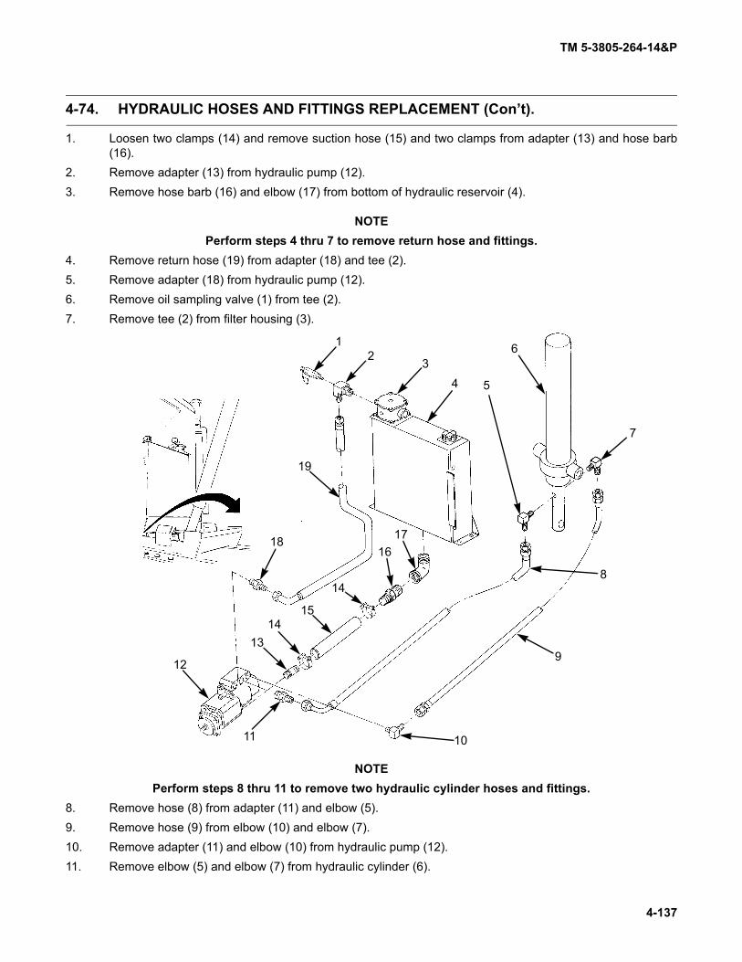
TM 5-3805-264-14&P
4-137
4-74. HYDRAULIC HOSES AND FITTINGS REPLACEMENT (Con’t).
1. Loosen two clamps (14) and remove suction hose (15) and two clamps from adapter (13) and hose barb(16).
2. Remove adapter (13) from hydraulic pump (12).3. Remove hose barb (16) and elbow (17) from bottom of hydraulic reservoir (4).
NOTEPerform steps 4 thru 7 to remove return hose and fittings.
4. Remove return hose (19) from adapter (18) and tee (2).5. Remove adapter (18) from hydraulic pump (12).6. Remove oil sampling valve (1) from tee (2).7. Remove tee (2) from filter housing (3).
NOTEPerform steps 8 thru 11 to remove two hydraulic cylinder hoses and fittings.
8. Remove hose (8) from adapter (11) and elbow (5).9. Remove hose (9) from elbow (10) and elbow (7).10. Remove adapter (11) and elbow (10) from hydraulic pump (12).11. Remove elbow (5) and elbow (7) from hydraulic cylinder (6).
12
11 10
1314
15
14
161718
19
12 3
4 5
6
7
8
9

TM 5-3805-264-14&P
4-138
4-74. HYDRAULIC HOSES AND FITTINGS REPLACEMENT (Con’t).
Clean and inspect components in accordance with Chapter 4, Section III, General Maintenance Instruc-tions.
NOTE• Use antiseize tape on all pipe threads (paragraph 4-22).• Install hose support clamps and new tie wraps as necessary.• Perform steps 1 thru 4 to install two hydraulic cylinder hoses and fittings.
1. Install elbow (5) and elbow (7) to hydraulic cylinder (6).
2. Install elbow (10) and adapter (11) to hydraulic pump (12).
3. Install hose (9) to elbow (7) and elbow (10).
4. Install hose (8) to adapter (11) and elbow (5).
b. CLEANING AND INSPECTION
c. INSTALLATION
12
11 10
1314
15
14
161718
19
12 3
4 5
6
7
8
9

TM 5-3805-264-14&P
4-139
4-74. HYDRAULIC HOSES AND FITTINGS REPLACEMENT (Con’t).
NOTEPerform steps 5 thru 7 to install suction hose.
5. Install elbow (17) and hose barb (16) to bottom of hydraulic reservoir (4).6. Install adapter (13) to hydraulic pump (12).7. Install suction hose (15) and two clamps (14) to adapter (13) and hose barb (16). Tighten clamps.
NOTEPerform steps 8 thru 11 to install return hose and fittings.
8. Install tee (2) on filter housing (3).9. Install oil sampling valve (1) on tee (2).10. Install adapter (18) to hydraulic pump (12).11. Install return hose (19) to adapter (18) and tee (2).
FOLLOW-ON TASKS:• Install transmission tunnel access cover (TM 9-2320-363-20 or TM 9-2320-302-20).• Fill hydraulic reservoir (Chapter 3, Section I).• Remove body props and lower dump body (paragraph 2-15).

TM 5-3805-264-14&P
4-140
4-75. HYDRAULIC RESERVOIR REPLACEMENT.
This task covers:
a. Removalb. Cleaning and Inspection
c. Installation
Initial Setup:
Equipment Conditions:
• Dump body raised and supported on body props(paragraph 2-15).
• Hydraulic oil drained (Chapter 3, Section I).
Tools/Test Equipment:
• General mechanic's tool kit (Item 8, Appendix I)• Cap and plug set (Item 1, Appendix I)• Nylon sling (Item 6, Appendix I)• Adjustable wrench (Item 10, Appendix I)• Torque wrench (Item 11, Appendix I)• Suitable lifting device
Materials/Parts:• Rags (Item 16, Appendix F)• Antiseize tape (Item 21, Appendix F)• Four locknuts • Four lockwashers
Personnel Required: Two
General Safety Instructions:• NEVER work under a raised dump body unless it
is secured in the raised position with body propsand dump body is EMPTY.
• DO NOT disconnect hydraulic lines while engineis running.
• Use extreme caution when handling heavy parts.
WARNING
• NEVER work under a raised dump body unless it is secured in the raised posi-tion with body props and dump body is EMPTY. Failure to follow this warningmay result in death or injury to personnel.
• DO NOT disconnect hydraulic lines while engine is running. Engine must beshut down and dump body fully lowered or supported on body props beforelines are disconnected. Escaping hydraulic fluid under pressure can penetratethe skin, causing serious injury to personnel.
CAUTION
Hoses and ports in hydraulic components should be plugged to prevent contamina-tion of hydraulic system (paragraph 4-21).
NOTE• Hoses should be tagged before removal (paragraph 4-17).
• Use a suitable container to catch any draining hydraulic fluid. Ensure that allspills are cleaned up.
1. Disconnect hydraulic return hose (4) from tee (2).
a. REMOVAL

TM 5-3805-264-14&P
4-141
4-75. HYDRAULIC RESERVOIR REPLACEMENT (Con’t).
2. Remove tee (2) with oil sampling valve (3) fromfilter housing (1).
3. Loosen clamp (10) and disconnect suctionhose (11) from hose barb (12).
4. Remove hose barb (12) and elbow (13) fromhydraulic reservoir (15).
5. Attach a nylon sling and suitable lifting deviceto hydraulic reservoir (15). Take up slack insling.
6. Remove four locknuts (9), spacers (8), lock-washers (7), washers (6), and screws (5). Dis-card locknuts and lockwashers.
WARNING
Use extreme care when handlingheavy parts. Lifting cables, chains,hooks, and slings must be in goodcondition and of suitable capacity.Keep clear of parts supported onlyby lifting device. Failure to followthis warning may result in death orinjury to personnel and damage toequipment
7. Remove hydraulic reservoir (15) from cylindersupport frame (14).
Clean and inspect components in accordance with Chapter 4, Section III, General Maintenance Instruc-tions.
14
13
12
11
10 9
5
678
4
3
2
1
15
b. CLEANING AND INSPECTION

TM 5-3805-264-14&P
4-142
4-75. HYDRAULIC RESERVOIR REPLACEMENT (Con’t).
WARNING
Use extreme care when handling heavy parts. Lifting cables, chains, hooks, andslings must be in good condition and of suitable capacity. Keep clear of parts sup-ported only by lifting device. Failure to follow this warning may result in death orinjury to personnel and damage to equipment.
NOTEUse antiseize tape on all pipe threads (paragraph 4-22).
1. Attach a nylon sling and suitable lifting deviceto hydraulic reservoir (15). Take up slack insling.
2. Position hydraulic reservoir (15) on cylindersupport frame (14).
3. Install four screws (5), washers (6), new lock-washers (7), spacers (8), and new locknuts (9).Torque locknuts to 100-110 lb.-ft. (136-149N•m). Remove nylon sling.
4. Install elbow (13) and hose barb (12) tohydraulic reservoir (15).
5. Connect suction hose (11) to hose barb (12)and tighten clamp (10).
6. Install tee (2) with oil sampling valve (3) to filterhousing (1).
7. Connect hydraulic return hose (4) to tee (2).
FOLLOW-ON TASKS:• Fill hydraulic reservoir (Chapter 3, Section I).• Remove body props and lower dump body (paragraph 2-15).
c. INSTALLATION
14
13
12
11
10 9
5
678
4
3
2
1
15

TM 5-3805-264-14&P
4-143
4-76. HYDRAULIC RESERVOIR REPAIR.
This task covers:a. Disassemblyb. Cleaning and Inspection
c. Assembly
Initial Setup:Tools/Test Equipment:
• General mechanic's tool kit (Item 8, Appendix I)• Cap and plug set (Item 1, Appendix I)
Materials/Parts:• Lubricating oil (Item 13 or 14, Appendix F)
Materials/Parts (Con’t):
• Rags (Item 16, Appendix F)• Antiseize tape (Item 21, Appendix F)• One preformed packing• One seal
CAUTION
Ports in reservoir should be plugged to pre-vent contamination of hydraulic system(paragraph 4-21).
1. Remove hydraulic oil filter service indicatorgage (paragraph 4-79).
2. Remove hydraulic oil filter element (paragraph4-78).
3. Remove four screws (1) and filter housing (13)from hydraulic reservoir (11).
4. Remove pipe (12) from filter housing (13).
5. Remove seal (14) from filter housing mountingflange. Discard seal.
6. Separate filter housing (13) and remove pre-formed packing (15). Discard preformed pack-ing.
7. Remove fill cap (2), six screws (3), and strainer(4).
8. Remove sight tube (6) and two elbows (5).
9. Remove drain plug (10), elbow (7), hose (8),and cap (9).
Clean and inspect components in accor-dance with Chapter 4, Section III, General Mainte-nance Instructions.
a. DISASSEMBLY
b. CLEANING AND INSPECTION
1
2
3
4 5
6
5
7
8
10
11
9
12
1314
15
13

TM 5-3805-264-14&P
4-144
4-76. HYDRAULIC RESERVOIR REPAIR (Con’t).
NOTE
Use antiseize tape on all pipethreads (paragraph 4-22).
1. Install drain plug (10), elbow (7), hose (8), andcap (9).
NOTE
For information on manufacturingsight tube, refer to Appendix G,Illustrated List of ManufacturedItems.
2. Install two elbows (5) and sight tube (6) tohydraulic reservoir (11).
3. Install strainer (4) with six screws (3). Install fillcap (2).
NOTE
Apply a light coat of lubricating oilto preformed packing and seal asthey are assembled.
4. Assemble filter housing (13) with new pre-formed packing (15).
5. Install new seal (14) in filter housing mountingflange.
6. Install pipe (12) to filter housing (13).
7. Install filter housing (13) to hydraulic reservoir(11) with four screws (1).
8. Install hydraulic oil filter element (paragraph 4-78).
9. Install hydraulic oil filter service indicator gage(paragraph 4-79).
FOLLOW-ON TASKS:• Fill hydraulic reservoir (Chapter 3, Section I).
c. ASSEMBLY
1
2
3
45
6
5
7
8
10
11
9
12
13
1415
13

TM 5-3805-264-14&P
4-145
4-77. HYDRAULIC OIL FILTER ELEMENT REPLACEMENT.
This task covers:a. Removalb. Cleaning and Inspection
c. Installation
Initial Setup:Equipment Conditions:
• Dump body raised and supported on body props(paragraph 2-15).
Tools/Test Equipment:
• General mechanic's tool kit (Item 8, Appendix I)• Cap and plug set (Item 1, Appendix I)
Materials/Parts:
• Lubricating oil (Item 13 or 14, Appendix F)
Materials/Parts (Con’t):• Rags (Item 16, Appendix F)• One oil filter element• One preformed packing
General Safety Instructions:• NEVER work under a raised dump body unless it
is secured in the raised position with body propsand dump body is EMPTY.
• DO NOT disconnect hydraulic lines while engineis running.
WARNING
• NEVER work under a raised dump body unless it is secured in the raised posi-tion with body props and dump body is EMPTY. Failure to follow this warningmay result in death or injury to personnel.
• DO NOT disconnect hydraulic lines while engine is running. Engine must beshut down and dump body fully lowered or supported on body props beforelines are disconnected. Escaping hydraulic fluid under pressure can penetratethe skin, causing serious injury to personnel.

TM 5-3805-264-14&P
4-146
4-77. HYDRAULIC OIL FILTER ELEMENT REPLACEMENT (Con’t).
CAUTION
Ports in reservoir should be plugged to prevent contamination of hydraulic system(paragraph 4-21).
1. Loosen four screws (1), rotate filter housing cover (5), and lift cover from filter housing (2).2. Remove oil filter element (3) and discard.3. Remove preformed packing (4) from groove in filter housing cover (5). Discard preformed packing.
Clean and inspect components in accordance with Chapter 4, Section III, General Maintenance Instruc-tions.
1. Coat new preformed packing (4) with lubricat-ing oil and install in groove of filter housingcover (5).
2. Install new oil filter element (3) to filter housing(2).
3. Install filter housing cover (5) to filter housing(2) with four screws (1).
FOLLOW-ON TASKS:• Remove body props and lower dump body (paragraph 2-15).• Fill hydraulic reservoir as necessary (Chapter 3, Section I).
a. REMOVAL
b. CLEANING AND INSPECTION
c. INSTALLATION1
2
4
5
3
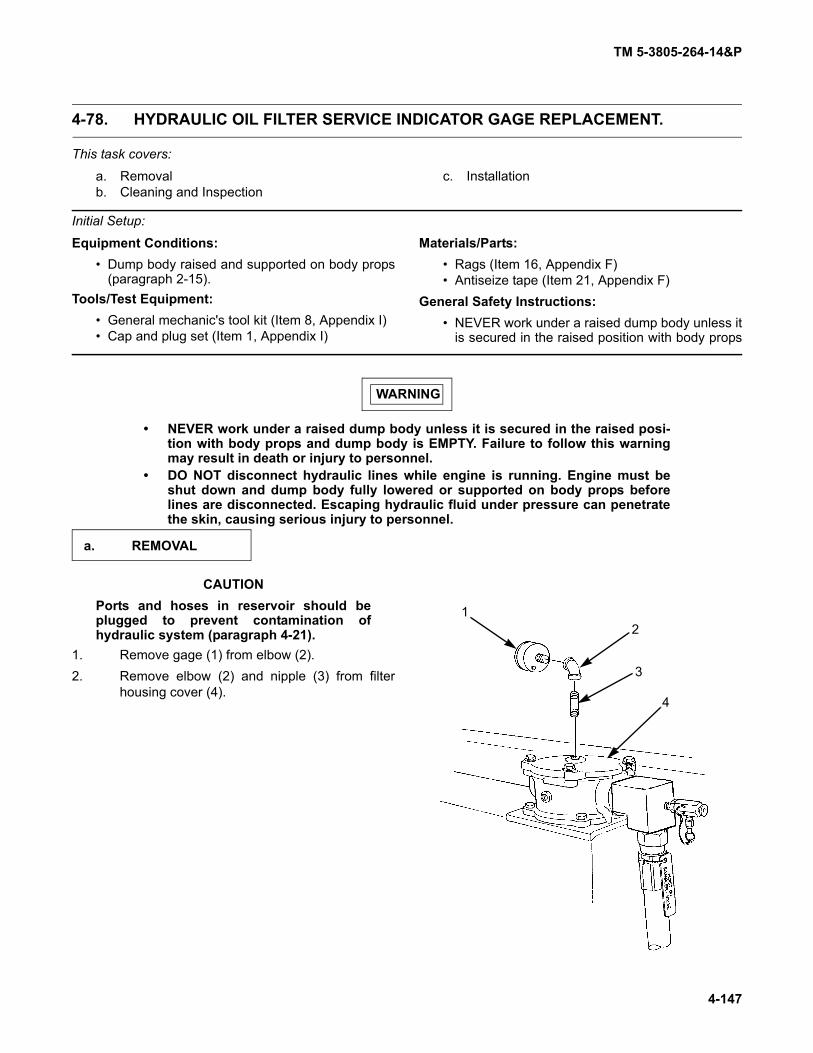
TM 5-3805-264-14&P
4-147
4-78. HYDRAULIC OIL FILTER SERVICE INDICATOR GAGE REPLACEMENT.
This task covers:
a. Removalb. Cleaning and Inspection
c. Installation
Initial Setup:
Equipment Conditions:• Dump body raised and supported on body props
(paragraph 2-15).Tools/Test Equipment:
• General mechanic's tool kit (Item 8, Appendix I)• Cap and plug set (Item 1, Appendix I)
Materials/Parts:• Rags (Item 16, Appendix F)• Antiseize tape (Item 21, Appendix F)
General Safety Instructions:• NEVER work under a raised dump body unless it
is secured in the raised position with body props
WARNING
• NEVER work under a raised dump body unless it is secured in the raised posi-tion with body props and dump body is EMPTY. Failure to follow this warningmay result in death or injury to personnel.
• DO NOT disconnect hydraulic lines while engine is running. Engine must beshut down and dump body fully lowered or supported on body props beforelines are disconnected. Escaping hydraulic fluid under pressure can penetratethe skin, causing serious injury to personnel.
CAUTIONPorts and hoses in reservoir should beplugged to prevent contamination ofhydraulic system (paragraph 4-21).
1. Remove gage (1) from elbow (2).2. Remove elbow (2) and nipple (3) from filter
housing cover (4).
a. REMOVAL
12
3
4

TM 5-3805-264-14&P
4-148
4-78 HYDRAULIC OIL FILTER SERVICE INDICATOR GAGE REPLACEMENT (Con’t).
Clean and inspect components in accor-dance with Chapter 4, Section III, General Mainte-nance Instructions.
NOTEUse antiseize tape on all pipethreads (paragraph 4-22).
1. Apply antiseize tape to pipe threads of nipple(3) and install nipple and elbow (2) to filterhousing cover (4).
2. Install gage (1) to elbow (2).
FOLLOW-ON TASKS:• Remove body props and lower dump body (paragraph 2-15).
b. CLEANING AND INSPECTION
c. INSTALLATION
12
3
4

TM 5-3805-264-14&P
4-149
Section X. PREPARATION FOR STORAGE OR SHIPMENT
Paragraph Page Number Paragraph Title Number
4-79. General . . . . . . . . . . . . . . . . . . . . . . . . . . . . . . . . . . . . . . . . . . . . . . . . . . . . . . . . . . . . . . . . . 4-1494-80. Definition of Administrative Storage . . . . . . . . . . . . . . . . . . . . . . . . . . . . . . . . . . . . . . . . . . . 4-1494-81. Preparation of Equipment for Administrative Storage. . . . . . . . . . . . . . . . . . . . . . . . . . . . . . 4-1494-82. Care of Equipment in Administrative Storage. . . . . . . . . . . . . . . . . . . . . . . . . . . . . . . . . . . . 4-151Table 4-4. Exercise Schedule . . . . . . . . . . . . . . . . . . . . . . . . . . . . . . . . . . . . . . . . . . . . . . . . . . . . . . . . 4-1514-83. Procedures for Common Components and Miscellaneous Items. . . . . . . . . . . . . . . . . . . . . 4-1524-84. Removal of Equipment from Administrative Storage . . . . . . . . . . . . . . . . . . . . . . . . . . . . . . 4-1524-85. Preparation of Equipment for Shipment . . . . . . . . . . . . . . . . . . . . . . . . . . . . . . . . . . . . . . . . 4-152
4-79. GENERAL.
a. This chapter contains requirements and procedures for administrative storage of equipment that isissued to and in use by Army activities worldwide.
b. The requirements specified herein are necessary to maintain equipment in administrative storagein such a way as to achieve the maximum readiness condition.
c. Equipment that is placed in administrative storage should be capable of being readied to performits mission within a 24-hour period, or as otherwise may be prescribed by the approving authority. Before equip-ment is placed in administrative storage, a current Preventive Maintenance Checks and Services (PMCS) shouldbe completed and deficiencies corrected.
d. Report equipment in administrative storage as prescribed for all reportable equipment.
e. Perform inspections, maintenance services, and lubrication as specified herein.
f. Records and reports to be maintained for equipment in administrative storage are those pre-scribed by DA Pam 738-750 for equipment in use.
g. A 10% variance is acceptable on time used to determine the required maintenance actions.
h. Accomplishment of applicable PMCS, as mentioned throughout this chapter, will be on a semi-annual basis.
4-80. DEFINITION OF ADMINISTRATIVE STORAGE.
The placement of equipment in administrative storage can be for short periods of time when a shortageof maintenance effort exists. Items should be ready for use within the time factors as determined by the directingauthority. During the storage period, appropriate maintenance records will be kept.
4-81. PREPARATION OF EQUIPMENT FOR ADMINISTRATIVE STORAGE.
a. Storage Site. (1) Select the best available site for administrative storage. Separate stored equipment from
equipment in use. Conspicuously mark the area “Administrative Storage”.
(2) Covered space is preferred.
TM 5-3805-264-14&P
4-150
4-81. PREPARATION OF EQUIPMENT FOR ADMINISTRATIVE STORAGE (Con’t).
(3) Open sites should be improved hardstand, if available. Unimproved sites should be firm,well-drained, and free of excessive vegetation.
b. Storage Plan.
(1) Store equipment so as to provide maximum protection from the elements and to provideaccess for inspection, maintenance, and exercising. Anticipate removal or deployment problems and take suitableprecautions.
(2) Take into consideration environmental conditions, such as extreme heat or cold; highhumidity; blowing sand, dust, or loose debris; soft ground; mud; heavy snows; or any combination thereof, and takeadequate precautions.
(3) Establish a fire plan and provide for adequate fire fighting equipment and personnel.
c. Maintenance Services and Inspections.
(1) Maintenance Services. Prior to storage, perform the next scheduled PMCS.
(2) Inspection. Inspect and approve the equipment prior to storage. Do not place nonmission-capable equipment in storage.
d. Correction of Shortcomings and Deficiencies. Correct all shortcomings and deficiencies priorto storage, or obtain a deferment from the approving authority.
e. Lubrication. Lubricate equipment in accordance with Chapter 3, Section I.
f. General Cleaning, Painting, and Preservation.
CAUTION
DO NOT direct water under pressure against unsealed electrical systems or anyexterior opening. Failure to follow this caution may result in damage to equipment.
(1) Cleaning. Clean the equipment of dirt, grease, and other contaminants, but do not usevapor degreasing.
(2) Painting. Remove rust and damaged paint by scraping, wire brushing, sanding, or buffing.Sand to a smooth finish and spot paint as necessary (TB 43-0209).
(3) Preservation. After cleaning and drying, immediately coat unpainted metal surfaces withoil or grease, as appropriate.
NOTE• Place a piece of barrier material (Item 2, Appendix F) between desiccant bags
and metal surfaces.
• Air circulation under draped covers reduces deterioration from moisture orheat.
(4) Weatherproofing. Sunlight, heat, moisture (humidity), and dirt tend to accelerate deterio-ration. Install all covers authorized for the equipment. Close and secure all openings except those required forventing and draining. Seal openings to prevent the entry of rain, snow, or dust. Insert desiccant when completeseal is required. Place equipment, and provide blocking or framing, to allow for ventilation and water drainage.Support cover away from item surfaces which may rust, rot, or mildew.

TM 5-3805-264-14&P
4-151
4-82. CARE OF EQUIPMENT IN ADMINISTRATIVE STORAGE.
a. Maintenance Services. After equipment has been placed in administrative storage, inspect, ser-vice, and exercise as specified herein.
b. Inspection. Inspection will usually be visual and must consist of at least a walkaround examina-tion of all equipment to detect any deficiencies. Inspect equipment in open storage weekly and equipment in cov-ered storage monthly. Inspect all equipment immediately after any severe storm or environmental change. Thefollowing are examples of things to look for during a visual inspection:
(1) Low or flat tires.
(2) Coolant, fuel, or oil leaks.
(3) Condition of preservatives, seals, and wraps.
(4) Corrosion or other deterioration.
(5) Missing or damaged parts.
(6) Water in compartments.
(7) Any other readily recognizable shortcomings or deficiencies.
c. Repair During Administrative Storage. Keep equipment in an optimum state of readiness.Accomplish the required services and repairs as quickly as possible. Whenever possible, perform all maintenanceon-site.
d. Exercising. Exercise equipment in accordance with Table 4-4, Exercise Schedule, and the follow-ing instructions.
(1) Vehicle Major Exercise. Depreserve equipment by removing only that material restrictingexercise. Close all drains, remove blocks, and perform all BEFORE operational checks. Make several right and left90° turns. Make several hard braking stops without skidding. While exercising, and when it is safe and convenient,operate all other functional components and perform all DURING and AFTER operational checks.
(2) Scheduled Services. Scheduled services will include inspection per subparagraph b andwill be conducted in accordance with Chapter 4, Section IV, Unit Preventive Maintenance Checks and Services(PMCS). Lubricate in accordance with instructions in Chapter 3, Section I.
(3) Corrective Action. Immediately take action to correct shortcomings and deficienciesnoted. Record inspection and exercise results on DA Form 2404. Record and report all maintenance actions on DAForm 2407. After exercising, restore the preservation to the original condition. Replenish lubricants used duringexercising and note the amount on DA Form 2408.
Table 4-4. Exercise Schedule.
e. Rotation. Rotate items in accordance with any rotational plan that will keep the equipment in anoperational condition and reduce the maintenance effort.
Weeks 2 4 6 8 10 12 14 16 18 20 22 24
Scheduled Services X
Major Exercise X

TM 5-3805-264-14&P
4-152
4-83. PROCEDURES FOR COMMON COMPONENTS AND MISCELLANEOUS ITEMS.
a. Tires. Visually inspect tires during each walkaround inspection. This inspection includes checkingtires with a tire gage. Inflate, repair, or replace as necessary those found to be low, damaged, or excessively worn.Mark inflated and repaired tires with a crayon for checking at the next inspection.
b. Batteries. Leave batteries in place in equipment. Disconnect battery cables (TM 9-2320-363-20 orTM 9-2320-302-20). Ensure that batteries are fully charged when equipment is stored and are returned to a fullcharge during each equipment exercising.
c. Seals. Seals may develop leaks during storage or shortly thereafter. If leaking persists, refer to theapplicable maintenance section in this manual for corrective maintenance procedures.
4-84. REMOVAL OF EQUIPMENT FROM ADMINISTRATIVE STORAGE.
a. Activation. Restore the equipment to normal operating condition in accordance with the instruc-tions contained in Chapter 4, Section II.
b. Servicing. Resume the maintenance service schedule in effect at the commencement of storageor service the equipment before the scheduled dates in order to produce a staggered maintenance workload.
4-85. PREPARATION OF EQUIPMENT FOR SHIPMENT.
a. Refer to FM 55-21, TM 55-601, and TM 743-200-1 for additional instructions on processing, stor-age, and shipment of materiel.
b. Vehicles that have been removed from storage for shipment do not have to be reprocessed if theywill reach their destination within the administrative storage period. Reprocess only if inspection reveals any corro-sion or if anticipated in-transit weather conditions make it necessary.
c. When a vehicle is received and has already been processed for domestic shipment, as indicatedon DD Form 1397, it does not have to be reprocessed for storage unless corrosion and deterioration are found dur-ing the inspection upon receipt. List on SF Form 364 all discrepancies found because of poor preservation, pack-aging, packing, marking, handling, loading, storage, or excessive preservation. Repairs that cannot be handled bythe receiving unit must have tags attached listing needed repairs. A report of these conditions will be submitted bythe unit commander for action by an ordnance maintenance unit.
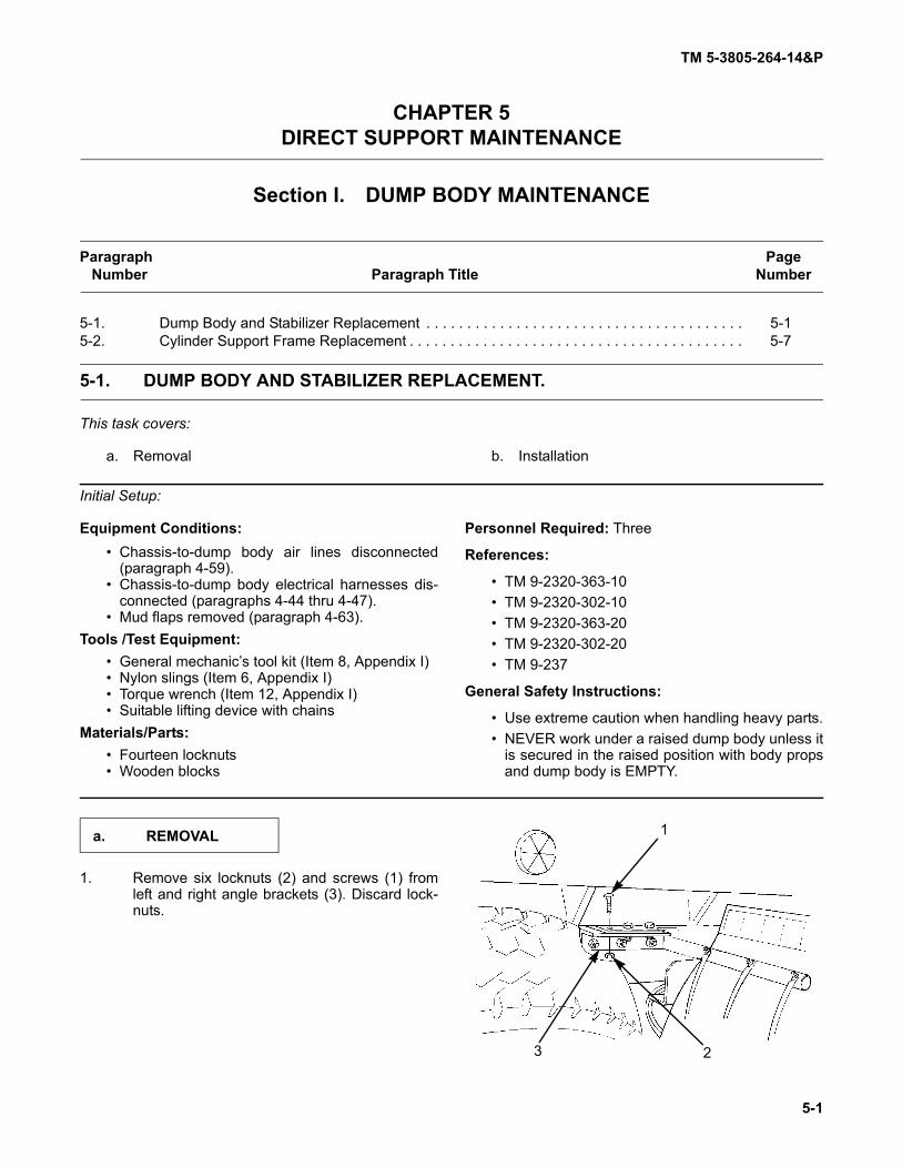
TM 5-3805-264-14&P
5-1
CHAPTER 5DIRECT SUPPORT MAINTENANCE
Section I. DUMP BODY MAINTENANCE
Paragraph PageNumber Paragraph Title Number
5-1. Dump Body and Stabilizer Replacement . . . . . . . . . . . . . . . . . . . . . . . . . . . . . . . . . . . . . . . 5-15-2. Cylinder Support Frame Replacement . . . . . . . . . . . . . . . . . . . . . . . . . . . . . . . . . . . . . . . . . 5-7
5-1. DUMP BODY AND STABILIZER REPLACEMENT.
This task covers:
a. Removal b. Installation
Initial Setup:
Equipment Conditions:• Chassis-to-dump body air lines disconnected
(paragraph 4-59).• Chassis-to-dump body electrical harnesses dis-
connected (paragraphs 4-44 thru 4-47).• Mud flaps removed (paragraph 4-63).
Tools /Test Equipment:• General mechanic’s tool kit (Item 8, Appendix I)• Nylon slings (Item 6, Appendix I)• Torque wrench (Item 12, Appendix I)• Suitable lifting device with chains
Materials/Parts:• Fourteen locknuts• Wooden blocks
Personnel Required: Three
References:
• TM 9-2320-363-10• TM 9-2320-302-10• TM 9-2320-363-20• TM 9-2320-302-20• TM 9-237
General Safety Instructions:
• Use extreme caution when handling heavy parts.• NEVER work under a raised dump body unless it
is secured in the raised position with body propsand dump body is EMPTY.
1. Remove six locknuts (2) and screws (1) fromleft and right angle brackets (3). Discard lock-nuts.
a. REMOVAL
3
1
2

TM 5-3805-264-14&P
5-2
5-1. DUMP BODY AND STABILIZER REPLACEMENT (Con’t).
2. Working from underside of vehicle, secure lower half (6) of stabilizer to upper half (5) and to dump body (4)using a suitable chain or nylon strap.
WARNING
• Use extreme care when han-dling heavy parts. Liftingcables, chains, hooks, andslings must be in good condi-tion and of suitable capacity.Keep clear of parts supportedonly by lifting device. Failure tofollow this warning may resultin death or injury to personneland damage to equipment.
• NEVER work under a raiseddump body unless it is securedin the raised position with bodyprops and dump body isEMPTY. Failure to follow thiswarning may result in death orinjury to personnel.
3. Raise front of dump body (4) and support onbody props (paragraph 2-15) using a suitablelifting device and chains.
4. Remove six locknuts (10) and screws (12) fromleft and right mounting brackets (11). Removebrackets from hydraulic cylinder pivots (14).Discard locknuts.
5. Disengage PTO (TM 9-2320-363-10 or TM 9-2320-302-10). Lower hydraulic cylinder (9) byplacing hydraulic control lever in cab in DOWNposition (paragraph 2-1). With hydraulic cylin-der lowered, place wooden blocks betweenbase of cylinder and cylinder support frame(13) to provide support.
7 6
4 5
10
1211
13
14
11
4
9

TM 5-3805-264-14&P
5-3
5-1. DUMP BODY AND STABILIZER REPLACEMENT (Con’t).
6. Using suitable lift and chains, lower front of dump body (4).7. Attach suitable lift and chains at four corners of dump body (4). Take up slack in chains with lift.8. Remove two locknuts (18) and screws (17) from rear hinge (15) and hinge pins (19). Discard locknuts.9. Remove left and right hinge pins (19) from rear hinge (15).
WARNING
Use extreme care when handling heavy parts. Lifting cables, chains, hooks, andslings must be in good condition and of suitable capacity. Keep clear of parts sup-ported only by lifting device. Failure to follow this warning may result in death orinjury to personnel and damage to equipment.
NOTEBefore removing dump body from vehicle chassis, perform a trial lift to ensure bodyis balanced and will lift straight and level from vehicle chassis.
10. Remove dump body (4) from vehicle chassis (7). Place dump body on suitable supports and remove liftingdevice and chains.
WARNING
Provide adequate ventilation and personal protective equipment before starting anywelding operation (TM 9-237). Contact your unit/local Industrial Hygienist or SafetyOfficer for assistance. Failure to follow this warning may result in injury to person-nel
CAUTION
Before welding, the following components must be disconnected: DDEC ECU, ABSECU, CTIS ECU, Datalogger, and batteries (TM 9-2320-363-20 or TM 9-2320-302-20).Failure to follow this caution may damage electronic components.
11. If stabilizer is damaged, it may be removed at this time. Refer to TM 9-237 Operator’s Manual for WeldingTheory and Application, for instructions on welding components.
15
1718
19
7
4

TM 5-3805-264-14&P
5-4
5-1. DUMP BODY AND STABILIZER REPLACEMENT (Con’t).
WARNING
• Use extreme care when handling heavy parts. Lifting cables, chains, hooks, andslings must be in good condition and of suitable capacity. Keep clear of partssupported only by lifting device. Failure to follow this warning may result indeath or injury to personnel and damage to equipment.
• Provide adequate ventilation and personal protective equipment before startingany welding operation (TM 9-237). Contact your unit/local Industrial Hygienist orSafety Officer for assistance. Failure to follow this warning may result in injuryto personnel.
CAUTION
Before welding, the following components must be disconnected: DDEC ECU, ABSECU, CTIS ECU, Datalogger, and batteries (TM 9-2320-363-20 or TM 9-2320-302-20).Failure to follow this caution may damage electronic components.
12. If removed, install stabilizer. Refer to TM 9-237Operator’s Manual for Welding Theory andApplication, for instructions on welding compo-nents.
13. Secure lower half (6) of stabilizer to upper half(5) and to dump body (4) using a suitable chainor nylon strap.
NOTEBefore lifting dump body, perform atrial lift to ensure body is balancedand will lift straight and level.
14. Attach suitable lift and chains at four corners ofdump body (4). Take up slack in chains with lift.
NOTEWhen positioning dump body on vehicle chassis, pay close attention to hydrauliccylinder positioning and rear hinge assembly alinement.
15. Lift dump body (4) and position over vehicle chassis (7). Lower body until rear hinge (15) and hinge pads(16) are alined and hydraulic cylinder is properly positioned in recess at front of dump body.
b. INSTALLATION
8 7 6
4 5
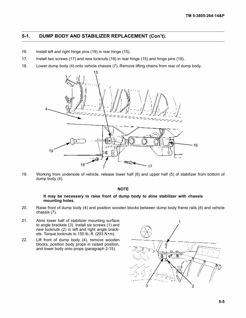
TM 5-3805-264-14&P
5-5
5-1. DUMP BODY AND STABILIZER REPLACEMENT (Con’t).
16. Install left and right hinge pins (19) in rear hinge (15).
17. Install two screws (17) and new locknuts (18) in rear hinge (15) and hinge pins (19).
18. Lower dump body (4) onto vehicle chassis (7). Remove lifting chains from rear of dump body.
19. Working from underside of vehicle, release lower half (6) and upper half (5) of stabilizer from bottom ofdump body (4).
NOTE
It may be necessary to raise front of dump body to aline stabilizer with chassismounting holes.
20. Raise front of dump body (4) and position wooden blocks between dump body frame rails (8) and vehiclechassis (7).
21. Aline lower half of stabilizer mounting surfaceto angle brackets (3). Install six screws (1) andnew locknuts (2) in left and right angle brack-ets. Torque locknuts to 150 lb.-ft. (203 N•m).
22. Lift front of dump body (4), remove woodenblocks, position body props in raised position,and lower body onto props (paragraph 2-15).
15
1718
19
7
4
16
3
1
2

TM 5-3805-264-14&P
5-6
5-1. DUMP BODY AND STABILIZER REPLACEMENT (Con’t).
23. Install left and right mounting brackets (11) oncylinder pivots (14).
NOTEIt may be necessary to raise and/orlower front of dump body to alinemounting brackets to dump body.
24. Aline mounting brackets (11) with mountingsurface of dump body (4).
25. Install six screws (12) and new locknuts (10) tosecure mounting brackets (11) to dump body(4). Torque locknuts to 150 lb.-ft. (203 N•m).
26. Remove dump body (4) from body props andlower body (paragraph 2-15).
27. Remove lifting device and chains from dumpbody (4).
FOLLOW-ON TASKS:• Connect chassis-to-dump body air lines (paragraph 4-59).• Connect chassis-to-dump body electrical harnesses (paragraphs 4-44 thru 4-47).• Install mud flaps (paragraph 4-63).
10
1211
13
14
11
4
9

TM 5-3805-264-14&P
5-7
5-2. CYLINDER SUPPORT FRAME REPLACEMENT.
This task covers:
a. Removal b. Installation
Initial Setup:
Equipment Conditions:
• Body up switch removed (paragraph 4-38).• Hydraulic reservoir removed (paragraph 4-75).• Hydraulic cylinder removed (paragraph 5-6).
Tools/Test Equipment:
• General mechanic’s tool kit (Item 8, Appendix I)• Nylon slings (Item 6, Appendix I)
Tools/Test Equipment (Con’t):• Torque wrench (Item 12, Appendix I)• Suitable lifting device
Materials/Parts:• Twenty-four locknuts
Personnel Required: ThreeGeneral Safety Instructions:
• Use extreme caution when handling heavy parts.
WARNING
Use extreme care when handling heavy parts. Lifting cables, chains, hooks, andslings must be in good condition and of suitable capacity. Keep clear of parts sup-ported only by lifting device. Failure to follow this warning may result in death orinjury to personnel and damage to equipment.
1. Attach slings to cylinder support frame (2) and attach slings to lifting device. Take up slack in slings with lift.
a. REMOVAL
2
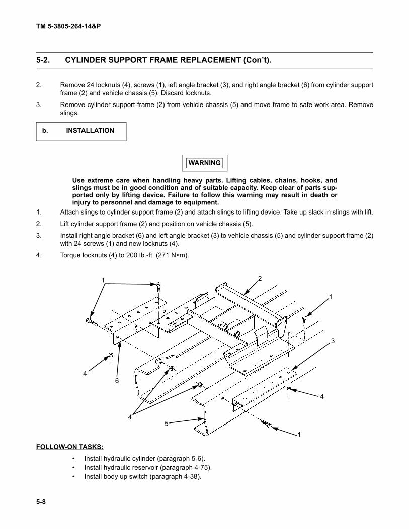
TM 5-3805-264-14&P
5-8
5-2. CYLINDER SUPPORT FRAME REPLACEMENT (Con’t).
2. Remove 24 locknuts (4), screws (1), left angle bracket (3), and right angle bracket (6) from cylinder supportframe (2) and vehicle chassis (5). Discard locknuts.
3. Remove cylinder support frame (2) from vehicle chassis (5) and move frame to safe work area. Removeslings.
WARNING
Use extreme care when handling heavy parts. Lifting cables, chains, hooks, andslings must be in good condition and of suitable capacity. Keep clear of parts sup-ported only by lifting device. Failure to follow this warning may result in death orinjury to personnel and damage to equipment.
1. Attach slings to cylinder support frame (2) and attach slings to lifting device. Take up slack in slings with lift.
2. Lift cylinder support frame (2) and position on vehicle chassis (5).
3. Install right angle bracket (6) and left angle bracket (3) to vehicle chassis (5) and cylinder support frame (2)with 24 screws (1) and new locknuts (4).
4. Torque locknuts (4) to 200 lb.-ft. (271 N•m).
FOLLOW-ON TASKS:
• Install hydraulic cylinder (paragraph 5-6).• Install hydraulic reservoir (paragraph 4-75).• Install body up switch (paragraph 4-38).
b. INSTALLATION
1 2
1
3
4
15
4
64
TM 5-3805-264-14&P
5-9
Section II. DUMP BODY ACCESSORY ITEMS MAINTENANCE
5-3. CARGO COVER REPAIR.
Repair cargo cover in accordance with FM 10-16, General Fabric Repair.

TM 5-3805-264-14&P
5-10
Section III. HYDRAULIC SYSTEM MAINTENANCE
Paragraph PageNumber Paragraph Title Number
5-4. Hydraulic Pump Replacement . . . . . . . . . . . . . . . . . . . . . . . . . . . . . . . . . . . . . . . . . . . . . . . 5-105-5. Hydraulic Pump Repair. . . . . . . . . . . . . . . . . . . . . . . . . . . . . . . . . . . . . . . . . . . . . . . . . . . . . 5-145-6. Hydraulic Cylinder Replacement . . . . . . . . . . . . . . . . . . . . . . . . . . . . . . . . . . . . . . . . . . . . . 5-205-7. Hydraulic Cylinder Repair . . . . . . . . . . . . . . . . . . . . . . . . . . . . . . . . . . . . . . . . . . . . . . . . . . . 5-23
5-4. HYDRAULIC PUMP REPLACEMENT.
This task covers:
a. Removal b. Cleaning and Inspection
c. Installation
Initial Setup:
Equipment Conditions:
• Hydraulic oil drained (Chapter 3, Section I).• Transmission tunnel access cover removed (TM
9-2320-363-20 or TM 9-2320-302-20).• Hydraulic control lever cable disconnected from
hydraulic pump (paragraph 4-73).
Tools/Test Equipment:
• General mechanic's tool kit (Item 8, Appendix I)• Cap and plug set (Item 1, Appendix I)• Adjustable wrench (Item 10, Appendix I)• Torque wrench (Item 11, Appendix I)
Materials/Parts:
• Rags (Item 16, Appendix F)• Marker tags (Item 20, Appendix F)• Antiseize tape (Item 21, Appendix F)• Four lockwashers
Personnel Required: Two
General Safety Instructions:
• DO NOT disconnect hydraulic lines while engineis running.
• Use extreme caution when handling heavy parts.
WARNING
DO NOT disconnect hydraulic lines while engine is running. Engine must be shutdown and dump body fully lowered or supported on body props before lines aredisconnected. Escaping hydraulic fluid under pressure can penetrate the skin,causing serious injury to personnel.
CAUTION
Hoses and ports in hydraulic components should be plugged to prevent contamina-tion of hydraulic system (paragraph 4-21).
a. REMOVAL

TM 5-3805-264-14&P
5-11
5-4. HYDRAULIC PUMP REPLACEMENT (Con’t).
NOTE
• Hoses should be tagged before removal (paragraph 4-17).
• A suitable container should be used to catch any draining hydraulic fluid.Ensure that all spills are cleaned up.
1. Loosen clamp (11) and disconnect suction hose (12) from adapter (13).
2. Remove adapter (13) from hydraulic pump (5).
3. Disconnect hose (19) from adapter (20). Disconnect hose (18) from adapter (17).
4. Remove adapters (17 and 20) from control valve (4).
5. Disconnect hose (15) from elbow (16).
6. Remove elbow (16) from control valve (4).
7. Remove nut (9) and washer (8) from stud (6) of hydraulic pump (5).
8. Remove two screws (10) and support bracket (7) from transmission housing (14).
WARNING
Use extreme care when handling heavy parts. Lifting cables, chains, hooks, andslings must be in good condition and of suitable capacity. Keep clear of parts sup-ported only by lifting device. Failure to follow this warning may result in death orinjury to personnel and damage to equipment.
9. Remove four nuts (3), lockwashers (2), screws (1), and hydraulic pump (5) from PTO (21). Discard lock-washers.
12
3
45
6
7
89
10
1112
1314
1516
1718
19
20
21

TM 5-3805-264-14&P
5-12
5-4. HYDRAULIC PUMP REPLACEMENT (Con’t).
Clean and inspect components in accordance with Chapter 4, Section III, General Maintenance Instruc-tions.
WARNING
Use extreme care when handling heavy parts. Lifting cables, chains, hooks, andslings must be in good condition and of suitable capacity. Keep clear of parts sup-ported only by lifting device. Failure to follow this warning may result in death orinjury to personnel and damage to equipment.
NOTEUse antiseize tape on all pipe threads (paragraph 4-22).
1. Install hydraulic pump (5) to PTO (21) with four screws (1), new lockwashers (2), and nuts (3).2. Install support bracket (7) to transmission housing (14) with two screws (10). Torque screws to 70-80 lb.-ft.
(95-108 N•m).3. Install washer (8) and nut (9) to stud (6) of hydraulic pump (5).4. Install elbow (16) to control valve (4).5. Connect hose (15) to elbow (16).
b. CLEANING AND INSPECTION
c. INSTALLATION
12
3
45
6
7
89
10
1112
1314
1516
1718
19
20
21

TM 5-3805-264-14&P
5-13
5-4. HYDRAULIC PUMP REPLACEMENT (Con’t).
6. Install adapters (17 and 20) to control valve (4).7. Connect hoses (18 and 19) to adapters (17 and 20).8. Install adapter (13) to hydraulic pump (5).9. Connect suction hose (12) to adapter (13) and tighten clamp (11).
FOLLOW-ON TASKS:• Fill hydraulic reservoir (Chapter 3, Section I).• Connect hydraulic control lever cable to hydraulic pump (paragraph 4-73).• Install transmission tunnel access cover (TM 9-2320-363-20 or TM 9-2320-302-20).

TM 5-3805-264-14&P
5-14
5-5. HYDRAULIC PUMP REPAIR.
This task covers:
a. Disassemblyb. Cleaning and Inspection
c. Assembly
Initial Setup:
Equipment Conditions:• Hydraulic pump removed (paragraph 5-4).
Tools/Test Equipment:• General mechanic’s tool kit (Item 8, Appendix I)• Machinist’s vise (Item 9, Appendix I)• Torque wrench (Item 12, Appendix I)• Socket wrench set (Item 13, Appendix I)• Deep well socket, 7/8 x 3/4 in. drive
Materials/Parts:• Grease (Item 11, Appendix F)
Materials/Parts (Con’t):• Lubricating oil (Item 14, Appendix F)• Rags (Item 16, Appendix F)• One lip seal• One retaining ring• Two check assemblies• Two gasket seals• Two ring seals• Four roller bearings• Twelve pocket seals
General Safety Instructions:• Use extreme caution when handling heavy parts.
WARNING
Use extreme care when handling heavy parts. Lifting cables, chains, hooks, andslings must be in good condition and of suitable capacity. Keep clear of parts sup-ported only by lifting device. Failure to follow this warning may result in death orinjury to personnel and damage to equipment.
CAUTION
Remove dirt from outside of hydraulic pump. Perform repair in a clean work area toprevent contaminants from causing equipment failure.
NOTEMark castings of pump to aid in assembly.
1. Remove retaining ring (1), spacer (2), and sealretainer (3) from drive shaft (4). Discard retain-ing ring.
a. DISASSEMBLY
12
34

TM 5-3805-264-14&P
5-15
5-5. HYDRAULIC PUMP REPAIR (Con’t).
2. Secure hydraulic pump in vise and removethree screws (5), two nuts (8), and five wash-ers (6) securing pump housings.
NOTENote stud location for assembly.
3. Remove stud (7).
CAUTION
Internal surfaces and parts of hydraulic pump are machined to strict manufacturingtolerances. Care must be taken not to damage machined surfaces.
NOTEDrive shaft and gearshaft may slide out with end housing.
4. Place hydraulic pump on clean, flat surface and separate end housing (11) from gear housing (13).5. Remove drive shaft (4) and gearshaft (9) from end housing (11).6. Remove thrust plate (10) from end housing (11). Remove six pocket seals (12) from thrust plate. Discard
pocket seals.
56
78 6
94
10 11
12
13

TM 5-3805-264-14&P
5-16
5-5. HYDRAULIC PUMP REPAIR (Con’t).
7. Remove two check assemblies (17) from endhousing (11). Discard check assemblies.
8. Remove two roller bearings (14), ring seals(15), and lip seal (16) from end housing (11).Discard roller bearings, ring seals, and lip seal.
9. Remove gear housing (13) from pump housing(19). Remove two gasket seals (18) from gearhousing. Discard gasket seals.
10. Remove thrust plate (20) and six pocket seals(21) from pump housing (19). Discard pocketseals.
11. Remove two roller bearings (22). Discard rollerbearings.
1415
11 16
17
18
19
13 18
21
20
22
1921

TM 5-3805-264-14&P
5-17
5-5. HYDRAULIC PUMP REPAIR (Con’t).
Clean and inspect components in accordance with Chapter 4, Section III, General Maintenance Instruc-tions and the following:
(a) Inspect drive shaft and gearshaft for scoring or grooving on teeth. Any scoring, groov-ing, or burring of outside diameter of teeth requires replacement of shafts as a set. Ifshafts are replaced, roller bearings must also be replaced.
(b) Inspect thrust plates for wear, pitting, or discoloration. If found, replace thrust plates.
NOTEApply a light coat of lubricating oil to surfaces of components as they are assem-bled.
1. Press two new roller bearings (22) into pump housing (19). Press two new ring seals (15) and new rollerbearings (14) into end housing (11).
2. Press new lip seal (16) into drive shaft side of end housing (11).3. Install two new check assemblies (17) to end housing (11).
4. Cut two pocket seals (12) 3/16 in. (4.8 mm)long and place in center slots of thrust plate(10). Use light grease to hold in place. Placethrust plate, with pocket seals facing machinedsurface, over bearings (14) of end housing (11)and tap to about 1/32 in. (0.8 mm) frommachined surface.
5. Insert remaining four pocket seals (12) intoplace around thrust plate (10). Tap thrust platedown onto machined surface. Cut excess sealfrom thrust plate.
b. CLEANING AND INSPECTION
c. ASSEMBLY
14 15
11 16
19
2217
1014 11
12

TM 5-3805-264-14&P
5-18
5-5. HYDRAULIC PUMP REPAIR (Con’t).
6. Repeat step 5 for thrust plate on pump housing (19).7. Install pump housing (19) in vise with machined surface facing up.
NOTEUse scribe marks from disassembly to properly assemble pump housings. Lighttapping with rubber hammer may be required to seat housings in place.
8. Install new gasket seal (18) in gear housing (13) and place gear housing on pump housing (19).9. Install drive shaft (4) and gearshaft (9) into gear housing (13). Check for free turning of gears.10. Install new gasket seal (18) on gear housing (13). Apply light coat of grease to drive shaft (4).11. Place end housing (11) over drive shaft (4) and carefully press housing in place seating gears against
thrust plate (10).
NOTEEnsure that stud is installed in correct location as noted in disassembly.
12. Install three screws (5), three washers (6), stud(7), washer (6), and nut (8) in place to securepump housings. Tighten screws and stud incrisscross pattern and torque to 200 lb.-ft. (271N•m). Check for free shaft movement by turn-ing drive shaft (4) with a wrench.
13. Install one washer (6) and nut (8) on stud (7)and tighten by hand.
1813
94
1811
10
19
56
78 6

TM 5-3805-264-14&P
5-19
5-5. HYDRAULIC PUMP REPAIR (Con’t).
14. Install seal retainer (3), spacer (2), and newretaining ring (1) on drive shaft (4).
FOLLOW-ON TASKS:• Install hydraulic pump (paragraph 5-4).
12
34

TM 5-3805-264-14&P
5-20
5-6. HYDRAULIC CYLINDER REPLACEMENT.
This task covers:
a. Removalb. Cleaning and Inspection
c. Installation
Initial Setup:
Equipment Conditions:• Dump body raised and supported on body props
(paragraph 2-15).• Cab shield removed (paragraph 4-62).• Hydraulic oil drained (Chapter 3, Section I).
Tools/Test Equipment:• General mechanic's tool kit (Item 8, Appendix I)• Cap and plug set (Item 1, Appendix I)• Nylon sling (Item 6, Appendix I)• Suitable lifting device
Materials/Parts:• Rags (Item 16, Appendix F)• Marker tags (Item 20, Appendix F)
Materials/Parts (Con’t):
• Seven locknuts• Two lockwashers
Personnel Required: Three
General Safety Instructions:
• NEVER work under a raised dump body unless itis secured in the raised position with body propsand dump body is EMPTY.
• DO NOT disconnect hydraulic lines while engineis running.
• Use extreme caution when handling heavy parts.• Hydraulic cylinder sleeves may extend down-
ward as hydraulic cylinder is lifted.
WARNING
• NEVER work under a raised dump body unless it is secured in the raised posi-tion with body props and dump body is EMPTY. Failure to follow this warningmay result in death or injury to personnel.
• DO NOT disconnect hydraulic lines while engine is running. Engine must beshut down and dump body fully lowered or supported on body props beforelines are disconnected. Escaping hydraulic fluid under pressure can penetratethe skin, causing serious injury to personnel.
CAUTION
Hoses and ports in hydraulic components should be plugged to prevent contamina-tion of hydraulic system (paragraph 4-21).
NOTE• Hoses should be tagged before removal (paragraph 4-17).• A suitable container should be used to catch any draining hydraulic fluid.
Ensure that all spills are cleaned up.
1. At lower end of hydraulic cylinder (1), disconnect hose assemblies (6) from elbows (5). Remove elbows.
a. REMOVAL

TM 5-3805-264-14&P
5-21
5-6. HYDRAULIC CYLINDER REPLACEMENT (Con’t).
WARNING
Use extreme care when handlingheavy parts. Lifting cables, chains,hooks, and slings must be in goodcondition and of suitable capacity.Keep clear of parts supported onlyby lifting device. Failure to followthis warning may result in death orinjury to personnel and damage toequipment.
2. Install lifting sling through loop in hydraulic cyl-inder (1) and attach lifting sling to lifting device.
3. Remove locknut (8), screw (10), and pivot pin(9) from cylinder support frame (7) and hydrau-lic cylinder (1). Discard locknut.
4. While holding hydraulic cylinder (1) securely,remove six locknuts (2), screws (4), and leftand right mounting brackets (3 and 11) fromdump body (12). Discard locknuts.
5. Remove left and right mounting brackets (3 and 11) from hydraulic cylinder (1).
WARNING
• Use extreme care when handling heavy parts. Lifting cables, chains, hooks, andslings must be in good condition and of suitable capacity. Keep clear of partssupported only by lifting device. Failure to follow this warning may result indeath or injury to personnel and damage to equipment.
• Hydraulic cylinder sleeves may extend downward as hydraulic cylinder is lifted.Expect sleeve movement any time hydraulic cylinder is handled. Failure to doso may result in serious injury to personnel.
6. Remove hydraulic cylinder (1) from vehicle. Move hydraulic cylinder to a safe work area.
1
2
12
11
34
5
6 76
5
8
9
10

TM 5-3805-264-14&P
5-22
5-6. HYDRAULIC CYLINDER REPLACEMENT (Con’t).
Clean and inspect components in accordance with Chapter 4, Section III, General Maintenance Instruc-tions.
WARNING
Use extreme care when handlingheavy parts. Lifting cables, chains,hooks, and slings must be in goodcondition and of suitable capacity.Keep clear of parts supported onlyby lifting device. Failure to followthis warning may result in death orinjury to personnel and damage toequipment.
1. Install lifting sling through loop in hydraulic cyl-inder (1) and attach lifting sling to lifting device.
2. Position hydraulic cylinder (1) to vehicle.
3. While holding hydraulic cylinder (1) securely,position left and right mounting brackets (3 and11) to hydraulic cylinder (1).
4. Install left and right mounting brackets (3 and11) to dump body (12) with six screws (4) andnew locknuts (2).
5. Install lower end of hydraulic cylinder (1) to cyl-inder support frame (7) with pivot pin (9), screw(10), and new locknut (8).
6. Remove lifting sling from lifting device andhydraulic cylinder (1).
7. Install two elbows (5) to lower end of hydrauliccylinder (1). Connect two hose assemblies (6)to elbows.
FOLLOW-ON TASKS:• Fill hydraulic reservoir (Chapter 3, Section I).• Remove body props and lower dump body (paragraph 2-15).• Install cab shield (paragraph 4-62).
b. CLEANING AND INSPECTION
c. INSTALLATION
1
2
12
11
34
5
6 76
5
8
9
10
TM 5-3805-264-14&P
5-23
5-7. HYDRAULIC CYLINDER REPAIR.
This task covers:
a. Disassemblyb. Cleaning and Inspection
c. Assembly
Initial Setup:
Equipment Conditions:
• Hydraulic cylinder removed (paragraph 5-6).
Tools/Test Equipment:
• General mechanic’s tool kit (Item 8, Appendix I)• Pliers, retaining ring (Item 5, Appendix I)• Nylon sling (Item 6, Appendix I)• Seal installer, 3 in. (Item 4, Appendix B)• Seal installer, 4 in. (Item 5, Appendix B)• Seal installer, 5 in. (Item 6, Appendix B)• Hydraulic cylinder disassembly tool (Appendix G)• Suitable lifting device
Materials/Parts:
• Lubricating oil (Item 14, Appendix F)• Rags (Item 16, Appendix F)• Marker tags (Item 20, Appendix F)• Masking tape (Item 23, Appendix F)• One parts kit
Personnel Required: Two
General Safety Instructions:
• Use extreme caution when handling heavy parts.• Hydraulic cylinder sleeves may extend down-
ward as hydraulic cylinder is lifted.
WARNING
• Use extreme care when handling heavy parts. Lifting cables, chains, hooks, andslings must be in good condition and of suitable capacity. Keep clear of partssupported only by lifting device. Failure to follow this warning may result indeath or injury to personnel and damage to equipment.
• Hydraulic cylinder sleeves may extend downward as hydraulic cylinder is lifted.Expect sleeve movement any time hydraulic cylinder is handled. Failure to doso may result in serious injury to personnel.
CAUTION
Perform hydraulic cylinder repair in a clean work area to prevent contaminants fromcausing equipment failure.
NOTE
A suitable container should be used to catch any draining hydraulic fluid. Ensurethat all spills are cleaned up.
a. DISASSEMBLY

TM 5-3805-264-14&P
5-24
5-7. HYDRAULIC CYLINDER REPAIR (Con’t).
1. Using overhead lifting device with nylon sling,move hydraulic cylinder assembly to a verticalposition with plunger (1) facing upward.Securely block hydraulic cylinder in verticalposition.
NOTEPerform steps 2 thru 10 to removeplunger from sleeve.
2. Remove retaining ring (2) from sleeve (3).
NOTE• Retaining rings, piston rings, seals, wear rings, guide rings, wipers, and wiper
retainers should be noted by name and installed position immediately afterremoval and replacement parts from parts kit tagged (paragraph 4-17) to aid ininstallation.
• Wiper retainer and seal should come out as plunger is lifted a few inches. If not,apply a three-inch strip of tape at a 45 degree angle to a cleaned section ofplunger. Lower and again lift plunger to remove wiper retainer and seal.
3. Lift plunger (1) to expose wiper retainer (5) andseal (6). Lower plunger and remove nylonsling. Remove wiper retainer and seal fromplunger. Remove wiper (4) from wiper retainer.Discard wiper, wiper retainer, and seal.Remove tape from plunger, if used.
2
3
1
1
4
5
6
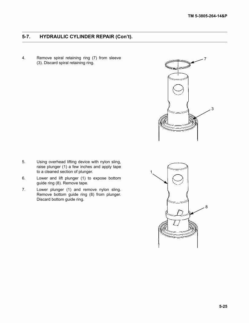
TM 5-3805-264-14&P
5-25
5-7. HYDRAULIC CYLINDER REPAIR (Con’t).
4. Remove spiral retaining ring (7) from sleeve(3). Discard spiral retaining ring.
5. Using overhead lifting device with nylon sling,raise plunger (1) a few inches and apply tapeto a cleaned section of plunger.
6. Lower and lift plunger (1) to expose bottomguide ring (8). Remove tape.
7. Lower plunger (1) and remove nylon sling.Remove bottom guide ring (8) from plunger.Discard bottom guide ring.
7
3
8
1

TM 5-3805-264-14&P
5-26
5-7. HYDRAULIC CYLINDER REPAIR (Con’t).
8. Using two small screwdrivers, remove bottomretaining ring (9) from groove of sleeve (3).Position four hydraulic cylinder disassemblytools, equally spaced, between bottom retain-ing ring and sleeve.
NOTEHydraulic cylinder disassemblytools will fall free as plunger, withbottom retaining ring, is removedfrom sleeve.
9. Remove plunger (1) from sleeve (3). Removenylon sling and bottom retaining ring (9) fromplunger.
10. Remove wear ring (10), piston ring (11), and two piston rings (12) from other end of plunger (1). Discardwear ring.
NOTEPerform steps 11 thru 18 to removenext sleeve.
11. Remove retaining ring (13) from sleeve (14).
1
3
9
1121110
13
14

TM 5-3805-264-14&P
5-27
5-7. HYDRAULIC CYLINDER REPAIR (Con’t).
NOTE
Hydraulic cylinder may be posi-tioned horizontally and tipped toextend sleeve. Wiper retainer andseal should come out as sleeve isextended a few inches. If not, applya three-inch strip of tape at a 45degree angle to a cleaned section ofsleeve. Retract and again extendsleeve to remove wiper retainer andseal.
12. Extend sleeve (3) to expose wiper retainer (16)and seal (17). Remove wiper retainer and sealfrom sleeve. Remove wiper (15) from wiperretainer. Discard wiper, wiper retainer, andseal. Remove tape from sleeve, if used.
13. Retract sleeve (3). Remove spiral retainingring (18) from sleeve (14). Discard spiralretaining ring.
14. Extend sleeve (3) a few inches and apply tapeto a cleaned section of sleeve.
15. Retract and extend sleeve (3) to expose bot-tom guide ring (19). Remove and discard bot-tom guide ring.
3
15
16
17
3
18
14
19
3

TM 5-3805-264-14&P
5-28
5-7. HYDRAULIC CYLINDER REPAIR (Con’t).
16. Using two small screwdrivers, remove bottomretaining ring (20) from groove of sleeve (14).Position four hydraulic cylinder disassemblytools, equally spaced, between bottom retain-ing ring and sleeve.
NOTEHydraulic cylinder disassemblytools will fall free as sleeve, withbottom retaining ring, is removedfrom larger sleeve.
17. Remove sleeve (3) from sleeve (14). Removebottom retaining ring (20) from sleeve (3).
18. Remove wear ring (21), piston ring (22), and two piston rings (23) from other end of sleeve (3). Discardwear ring.
NOTEPerform steps 19 thru 26 to removenext sleeve.
19. Remove retaining ring (24) from barrel (25).
14
3
20
3232221
24
25

TM 5-3805-264-14&P
5-29
5-7. HYDRAULIC CYLINDER REPAIR (Con’t).
NOTEWiper retainer and seal shouldcome out as sleeve is extended afew inches. If not, apply a three-inchstrip of tape at a 45 degree angle toa cleaned section of sleeve. Retractand again extend sleeve to removewiper retainer and seal.
20. Extend sleeve (14) to expose wiper retainer(27) and seal (28). Remove wiper retainer andseal from sleeve. Remove wiper (26) fromwiper retainer. Discard wiper, wiper retainer,and seal. Remove tape from sleeve, if used.
21. Retract sleeve (14). Remove spiral retainingring (29) from barrel (25). Discard spiral retain-ing ring.
22. Extend sleeve (14) a few inches and applytape to a cleaned section of sleeve.
23. Retract and extend sleeve (14) to expose bot-tom guide ring (30). Remove and discard bot-tom guide ring.
14
26
27
28
29
2514
14
30
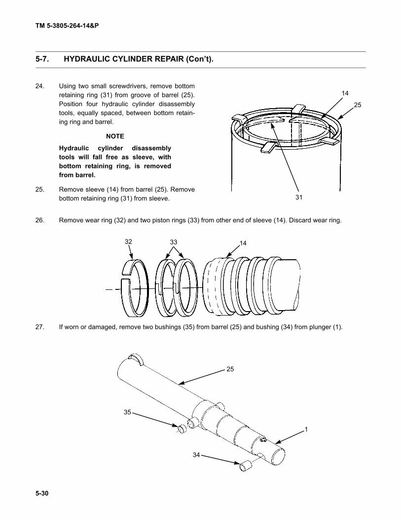
TM 5-3805-264-14&P
5-30
5-7. HYDRAULIC CYLINDER REPAIR (Con’t).
24. Using two small screwdrivers, remove bottomretaining ring (31) from groove of barrel (25).Position four hydraulic cylinder disassemblytools, equally spaced, between bottom retain-ing ring and barrel.
NOTE
Hydraulic cylinder disassemblytools will fall free as sleeve, withbottom retaining ring, is removedfrom barrel.
25. Remove sleeve (14) from barrel (25). Removebottom retaining ring (31) from sleeve.
26. Remove wear ring (32) and two piston rings (33) from other end of sleeve (14). Discard wear ring.
27. If worn or damaged, remove two bushings (35) from barrel (25) and bushing (34) from plunger (1).
31
14
25
32 33 14
25
1
35
34

TM 5-3805-264-14&P
5-31
5-7. HYDRAULIC CYLINDER REPAIR (Con’t).
Clean and inspect components in accordance with Chapter 4, Section III, General Maintenance Instruc-tions.
WARNING
• Use extreme care when handling heavy parts. Lifting cables, chains, hooks, andslings must be in good condition and of suitable capacity. Keep clear of partssupported only by lifting device. Failure to follow this warning may result indeath or injury to personnel and damage to equipment.
• Hydraulic cylinder sleeves may extend downward as hydraulic cylinder is lifted.Expect sleeve movement any time hydraulic cylinder is handled. Failure to doso may result in serious injury to personnel.
NOTE
• Apply a light coat of lubricating oil to surfaces of components as they areassembled.
• Assemble hydraulic cylinder starting with the largest diameter sleeve and work-ing inward.
1. If removed, install two bushings (35) to barrel (25) and bushing (34) to plunger (1).
NOTE
Perform steps 2 thru 7 to install largest diameter sleeve.
2. With hydraulic cylinder components in horizontal position, install two piston rings (33) and new wear ring(32) to sleeve (14).
3. Install sleeve (14) to barrel (25) and install bot-tom retaining ring (31) to barrel using 5 in. sealinstallation tool.
b. CLEANING AND INSPECTION
c. ASSEMBLY
31
25
14

TM 5-3805-264-14&P
5-32
5-7. HYDRAULIC CYLINDER REPAIR (Con’t).
4. Install new bottom guide ring (30) and new spi-ral retaining ring (29).
5. Install new seal (28).6. Install new wiper (26) to new wiper retainer
(27) and install wiper retainer.7. Install retaining ring (24).
NOTE
Perform steps 8 thru 13 to install next sleeve.
8. Install two piston rings (23), piston ring (22), and new wear ring (21) to sleeve (3).
24
26
27
28
29
30
3232221
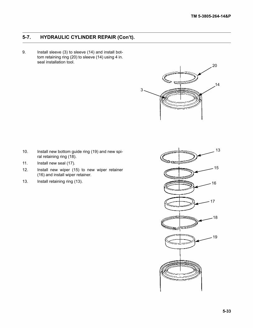
TM 5-3805-264-14&P
5-33
5-7. HYDRAULIC CYLINDER REPAIR (Con’t).
9. Install sleeve (3) to sleeve (14) and install bot-tom retaining ring (20) to sleeve (14) using 4 in.seal installation tool.
10. Install new bottom guide ring (19) and new spi-ral retaining ring (18).
11. Install new seal (17).12. Install new wiper (15) to new wiper retainer
(16) and install wiper retainer.13. Install retaining ring (13).
20
143
13
15
16
17
18
19

TM 5-3805-264-14&P
5-34
5-7. HYDRAULIC CYLINDER REPAIR (Con’t).
NOTEPerform steps 14 thru 19 to install plunger.
14. Install two piston rings (12), piston ring (11), and new wear ring (10) to plunger (1).
15. Install plunger (1) to sleeve (3) and install bot-tom retaining ring (9) to sleeve using 3 in. sealinstallation tool.
1121110
9
1
3

TM 5-3805-264-14&P
5-35/(5-36 Blank)
5-7. HYDRAULIC CYLINDER REPAIR (Con’t).
16. Install new bottom guide ring (8) and new spi-ral retaining ring (7).
17. Install new seal (6).18. Install new wiper (4) to new wiper retainer (5)
and install wiper retainer.19. Install retaining ring (2).
FOLLOW-ON TASKS:• Install hydraulic cylinder (paragraph 5-6).
2
4
5
6
7
8


TM 5-3805-264-14&P
6-1/(6-2 Blank)
CHAPTER 6GENERAL SUPPORT MAINTENANCE
There is no General Support Maintenance for the M917A1, M917A1 w/MCS, M917A2, and M917A2w/MCS dump truck body.


TM 5-3805-264-14&P
A-1
APPENDIX AREFERENCES
A-1. SCOPE.
This appendix lists all forms, field manuals, technical manuals, and other publications referenced in thismanual and that apply to the operation and maintenance of the M917A1, M917A1 w/MCS, M917A2, andM917A2 w/MCS Dump Truck Body.
A-2. PUBLICATION INDEX.
DA Pam 25-30, Consolidated Index of Army Publications and Blank Forms, should be consulted fre-quently for latest changes or revisions and for new publications relating to material covered in this technical man-ual.
A-3. FORMS.
Refer to DA Pam 738-750, Functional Users Manual for the Army Maintenance Management System(TAMMS), for instructions on the use of maintenance forms.
Equipment Control Record . . . . . . . . . . . . . . . . . . . . . . . . . . . . . . . . . . . . . . . . . . . . . . . . . . . . DA Form 2408-9Equipment Inspection and Maintenance Worksheet . . . . . . . . . . . . . . . . . . . . . . . . . . . . . . . . . . .DA Form 2404Equipment Log Assembly (Records) . . . . . . . . . . . . . . . . . . . . . . . . . . . . . . . . . . . . . . . . . . . . . . .DA Form 2408Maintenance Request . . . . . . . . . . . . . . . . . . . . . . . . . . . . . . . . . . . . . . . . . . . . . . . . . . . . . . . . . .DA Form 2407Preventive Maintenance Schedule and Record . . . . . . . . . . . . . . . . . . . . . . . . . . . . . . . . . . . . . . .DD Form 314Processing and Deprocessing Record for Shipment, Storage and Issue of
Vehicles and Spare Engines . . . . . . . . . . . . . . . . . . . . . . . . . . . . . . . . . . . . . . . . . . . . . . . . . .DD Form 1397Product Quality Deficiency Report. . . . . . . . . . . . . . . . . . . . . . . . . . . . . . . . . . . . . . . . . . . . . . . . . . SF Form 368Recommended Changes to Equipment Technical Publications . . . . . . . . . . . . . . . . . . . . . . . . DA Form 2028-2Recommended Changes to Publications and Blank Forms . . . . . . . . . . . . . . . . . . . . . . . . . . . . .DA Form 2028Report of Discrepancy (ROD) . . . . . . . . . . . . . . . . . . . . . . . . . . . . . . . . . . . . . . . . . . . . . . . . . . . . . SF Form 364
A-4. FIELD MANUALS.
Basic Cold Weather Manual . . . . . . . . . . . . . . . . . . . . . . . . . . . . . . . . . . . . . . . . . . . . . . . . . . . . . . . . .FM 31-70Chemical and Biological Contamination Avoidance . . . . . . . . . . . . . . . . . . . . . . . . . . . . . . . . . . . . . . . . .FM 3-3Field Behavior of NBC Agents (Including Smoke and Incendiaries) . . . . . . . . . . . . . . . . . . . . . . . . . . . . .FM 3-6First Aid Manual. . . . . . . . . . . . . . . . . . . . . . . . . . . . . . . . . . . . . . . . . . . . . . . . . . . . . . . . . . . . . . . . . FM 4-25.11General Fabric Repair . . . . . . . . . . . . . . . . . . . . . . . . . . . . . . . . . . . . . . . . . . . . . . . . . . . . . . . . . . . . . .FM 10-16NBC Decontamination . . . . . . . . . . . . . . . . . . . . . . . . . . . . . . . . . . . . . . . . . . . . . . . . . . . . . . . . . . . . . . . .FM 3-5NBC Protection . . . . . . . . . . . . . . . . . . . . . . . . . . . . . . . . . . . . . . . . . . . . . . . . . . . . . . . . . . . . . . . . . . . . .FM 3-4Northern Operations . . . . . . . . . . . . . . . . . . . . . . . . . . . . . . . . . . . . . . . . . . . . . . . . . . . . . . . . . . . . . . .FM 31-71Operation and Maintenance of Ordnance Materiel in Cold Weather (0° F to -65° F) . . . . . . . . . . . . . .FM 9-207Operational Terms and Symbols . . . . . . . . . . . . . . . . . . . . . . . . . . . . . . . . . . . . . . . . . . . . . . . . . . . . FM 101-5-1Railway Operating and Safety Rules. . . . . . . . . . . . . . . . . . . . . . . . . . . . . . . . . . . . . . . . . . . . . . . . . . .FM 55-21Visual Signals . . . . . . . . . . . . . . . . . . . . . . . . . . . . . . . . . . . . . . . . . . . . . . . . . . . . . . . . . . . . . . . . . . . .FM 21-60
TM 5-3805-264-14&P
A-2
A-5. TECHNICAL BULLETINS.
Color, Marking, and Camouflage Painting of Military Vehicles, Construction Equipment, and Materiels Handling Equipment . . . . . . . . . . . . . . . . . . . . . . . . . . TB 43-0209
Corrosion Prevention and Control Including Rustproofing Procedures for Tactical Vehicles and Trailers . . . . . . . . . . . . . . . . . . . . . . . . . . . . . . . . . . . . . . . . . . . . . . . . TB 43-0213
Equipment Improvement Report and Maintenance Digest (U.S. Series Army Tank-Automotive Command) Tank-Automotive Equipment . . . .TB 43-0001-39-Series
Warranty Program for M915 Family of Vehicles . . . . . . . . . . . . . . . . . . . . . . . . . . . . . . . . . . . TB 9-2320-363-15
A-6. TECHNICAL MANUALS.
Direct and General Support Maintenance Manual for M915A2, M916A1,M916A2, M917A1, and M917A1 wMCS, Chassis. . . . . . . . . . . . . . . . . . . . . . . . . . . . . . .TM 9-2320-363-34
Inspection, Care, and Maintenance of Antifriction Bearings . . . . . . . . . . . . . . . . . . . . . . . . . . . . . . . . .TM 9-214Materials Used for Cleaning, Preserving, Abrading, and Cementing Ordnance
Materiel and Related Materials Including Chemicals. . . . . . . . . . . . . . . . . . . . . . . . . . . . . . . . . .TM 9-247Operator’s Manual for M915A2, M916A1, M916A2,
M917A1, and M917A1 wMCS, Chassis . . . . . . . . . . . . . . . . . . . . . . . . . . . . . . . . . . . . . .TM 9-2320-363-10Operator’s Manual for M915A3, M916A3, M917A2, and M917A2 wMCS, Chassis . . . . . . . .TM 9-2320-302-10Operator’s Manual for Welding Theory and Application . . . . . . . . . . . . . . . . . . . . . . . . . . . . . . . . . . . .TM 9-237Painting Instructions for Army Materiel . . . . . . . . . . . . . . . . . . . . . . . . . . . . . . . . . . . . . . . . . . . . . . .TM 43-0139Procedures for Destruction of Equipment to Prevent Enemy Use
(Mobility Equipment Command) . . . . . . . . . . . . . . . . . . . . . . . . . . . . . . . . . . . . . . . . . . . . . TM 750-244-3Railcar Loading Procedures . . . . . . . . . . . . . . . . . . . . . . . . . . . . . . . . . . . . . . . . . . . . . . . . . . . . . . . .TM 55-601Storage and Materials Handling . . . . . . . . . . . . . . . . . . . . . . . . . . . . . . . . . . . . . . . . . . . . . . . . . . TM 743-200-1Unit, Direct Support, and General Support Repair Parts and Special Tools
List for M915A2, M916A1, M916A2, M917A1, and M917A1 wMCS, Chassis . . . . . . . TM 9-2320-363-24PUnit, Direct Support, and General Support Repair Parts and Special Tools
List for M915A3, M916A3, M917A2, and M917A2 wMCS, Chassis . . . . . . . . . . . . . . . TM 9-2320-302-24PUnit Maintenance Manual for M915A2, M916A1, M916A2,
M917A1, and M917A1 wMCS, Chassis . . . . . . . . . . . . . . . . . . . . . . . . . . . . . . . . . . . . . .TM 9-2320-363-20Unit Maintenance Manual for M915A3, M916A3, M917A2,
and M917A2 wMCS, Chassis . . . . . . . . . . . . . . . . . . . . . . . . . . . . . . . . . . . . . . . . . . . . . .TM 9-2320-302-20
A-7. OTHER PUBLICATIONS.
Abbreviations and Acronyms. . . . . . . . . . . . . . . . . . . . . . . . . . . . . . . . . . . . . . . . . . . . . . . . .ASME Y14.38-1999Army Medical Department Expendable/Durable Items . . . . . . . . . . . . . . . . . . . . . . . . . . . . . . . . . . . . CTA 8-100Expendable/Durable Items (Except Medical, Class V,
Repair Parts, and Heraldic Items) . . . . . . . . . . . . . . . . . . . . . . . . . . . . . . . . . . . . . . . . . . . . . . . . CTA 50-970Fuels and Lubricants Standardization Policy for Equipment Design, Operation, and Logistic
Support . . . . . . . . . . . . . . . . . . . . . . . . . . . . . . . . . . . . . . . . . . . . . . . . . . . . . . . . . . . . . . . . . . . . . . AR 70-12Military Standard Abbreviations for Use on Drawings, Specifications,
Standards, and in Technical Documents . . . . . . . . . . . . . . . . . . . . . . . . . . . . . . . . . . . . . . . . . MIL-STD-12DPrevention of Motor Vehicle Accidents . . . . . . . . . . . . . . . . . . . . . . . . . . . . . . . . . . . . . . . . . . . . . . . . AR 385-55

TM 5-3805-264-14&P
B-1
APPENDIX BMAINTENANCE ALLOCATION CHART
Section I. INTRODUCTION
B-1. THE ARMY MAINTENANCE SYSTEM MAINTENANCE ALLOCATION CHART (MAC).
a. This introduction (Section I) provides a general explanation of all maintenance and repair functionsauthorized at the two maintenance levels under the Two-Level Maintenance system concept.
b. The Maintenance Allocation Chart (MAC) in Section II designates overall authority and responsibil-ity for the performance of maintenance functions on the identified end item or component. The application of themaintenance functions to the end item or component will be consistent with the capacities and capabilities of thedesignated maintenance levels, which are shown on the MAC in column (4) as:
Field - includes subcolumns:
C - Operator/Crew O - UnitF - Direct Support
Sustainment - includes subcolumns:
H - General SupportD - Depot
c. Section III lists the tools and test equipment (both special tools and common tool sets) required foreach maintenance function as referenced from Section II.
d. Section IV contains supplemental instructions and explanatory notes for a particular maintenancefunction.
B-2. MAINTENANCE FUNCTIONS.
Maintenance functions are limited to and defined as follows:
a. Inspect. To determine the serviceability of an item by comparing its physical, mechanical, and/orelectrical characteristics with established standards through examination (e.g., by sight, sound, or feel).
b. Test. To verify serviceability by measuring the mechanical, pneumatic, hydraulic, or electrical char-acteristics of an item/end item and comparing those characteristics with prescribed standards.
c. Service. Operations required periodically to keep an item in proper operating condition; e.g., toclean (includes decontaminate, when required), to preserve, to drain, to paint, or to replenish fuel, lubricants,chemical fluids, or gases.
d. Adjust. To maintain or regulate, within prescribed limits, by bringing into proper position, or by set-ting the operating characteristics to specified parameters.
e. Aline. To adjust specified variable elements of an item to bring about optimum or desired perfor-mance.

TM 5-3805-264-14&P
B-2
B-2. MAINTENANCE FUNCTIONS (Con’t).
f. Calibrate. To determine and cause corrections to be made or to be adjusted on instruments ortest, measuring, and diagnostic equipment used in precision measurement. Consists of comparisons of two instru-ments, one of which is a certified standard of known accuracy, to detect and adjust any discrepancy in the accuracyof the instrument being compared.
g. Remove/Install. To remove and install the same item when required to perform service or othermaintenance functions. Install may be the act of emplacing, seating, or fixing onto position a spare, repair part, ormodule (component or assembly) in a manner to allow the proper functioning of an equipment or system.
h. Replace. To remove an unserviceable item and install a serviceable counterpart in its place.“Replace” is authorized by the MAC and assigned maintenance level is shown as the 3d position code of the SMRcode.
i. Repair. The application of maintenance services1 including fault location/troubleshooting2,removal/installation, and disassembly/assembly3 procedures, and maintenance actions4 to identify troubles andrestore serviceability to an item by correcting specific damage, fault, malfunction, or failure in a part, subassembly,module (component or assembly), end item, or system.
j. Overhaul. That maintenance effort (service/action) prescribed to restore an item to a completelyserviceable/operational condition as required by maintenance standards in the appropriate technical publications(i.e., DMWR). Overhaul is normally the highest degree of maintenance performed by the Army. Overhaul does notnormally return an item to like new condition.
k. Rebuild. Consists of those services/actions necessary for the restoration of unserviceable equip-ment to a like new condition in accordance with original manufacturing standards. Rebuild is the highest degree ofmateriel maintenance applied to Army equipment. The rebuild operation includes the act of returning to zero thoseage measurements (e.g., hours/miles) considered in classifying Army equipment/components.
B-3. EXPLANATION OF COLUMNS IN THE MAC, SECTION II.
a. Column (1) - Group Number. Column 1 lists functional group code numbers, the purpose ofwhich is to identify maintenance significant components, assemblies, subassemblies, and modules with the nexthigher assembly.
b. Column (2) - Component/Assembly. Column 2 contains the item names of components, assem-blies, subassemblies, and modules for which maintenance is authorized.
c. Column (3) - Maintenance Function. Column 3 lists the functions to be performed on the itemlisted in Column 2. (For detailed explanation of these functions, see paragraph B-2).
1. Services—Inspect, test, service, adjust, aline, calibrate, and/or replace.2. Fault location/troubleshooting—The process of investigating and detecting the cause of equipment malfunctioning; the act of iso-
lating a fault within a system or unit under test (UUT).3. Disassembly/assembly—The step-by-step breakdown (taking apart) of a spare/function group coded item to the level of its least
component, that is assigned an SMR code for the level or maintenance under consideration (i.e., identified as maintenance signif-icant).
4. Actions—Welding, grinding, riveting, straightening, facing, machining, and/or resurfacing.

TM 5-3805-264-14&P
B-3
B-3. EXPLANATION OF COLUMNS IN THE MAC, SECTION II (Con’t).
NOTE
When a complete replace or repair task performed at higher level maintenanceincludes lower level maintenance tasks (equipment condition/follow-on tasks), thelower level work time figures in the MAC must be added to the higher level worktime shown in the MAC to determine the total to accomplish that maintenance func-tion.
d. Column (4) - Maintenance Level. Column 4 specifies each level of maintenance authorized toperform each function listed in Column 3, by indicating a work time required (expressed as man-hours in wholehours or decimals) in the appropriate subcolumn. This work-time figure represents the active time required to per-form that maintenance function at the indicated level of maintenance. If the number or complexity of the taskswithin the listed maintenance function vary at different maintenance levels, appropriate work-time figures areshown for each level. The work-time figure represents the average time required to restore an item (assembly, sub-assembly, component, module, end item, or system) to a serviceable condition under typical field operating condi-tions. This time includes preparation time (equipment condition/follow-on tasks) (including any necessarydisassembly/assembly time), troubleshooting/fault location time, and quality assurance time in addition to the timerequired to perform the specific tasks identified for the maintenance functions authorized in the MAC. The symboldesignations for the various maintenance levels are as follows:
Field - includes subcolumns:
C - Operator/Crew O - UnitF - Direct Support
Sustainment - includes subcolumns:
H - General SupportD - Depot
e. Column (5) - Tools and Test Equipment Reference Code. Column 5 specifies, by code, thosecommon tool sets (not individual tools), common TMDE, and special tools, special TMDE, and special supportequipment required to perform the designated function. Codes are keyed to Tools and Test Equipment in SectionIII.
f. Column (6) - Remarks. When applicable, this column contains a letter code, in alphabetical order,which is keyed to the remarks contained in Section IV.
B-4. EXPLANATION OF COLUMNS IN TOOLS AND TEST EQUIPMENT REQUIRE-MENTS, SECTION III.
a. Column (1) - Tool or Test Equipment Reference Code. The tool or test equipment referencecode correlates with a code used in the MAC, Section II, column (5).
b. Column (2) - Maintenance Level. The lowest level of maintenance authorized to use the tool ortest equipment.
c. Column (3) - Nomenclature. Name or identification of the tool or test equipment.
d. Column (4) - National Stock Number. The National Stock Number of the tool or test equipment.
e. Column (5) - Tool Number. The manufacturer’s part number, model number, or type number.

TM 5-3805-264-14&P
B-4
B-5. EXPLANATION OF COLUMNS IN REMARKS, SECTION IV.
a. Column (1) - Remarks Code. The code recorded in Section II, column (6).b. Column (2) - Remarks. This column, along with the related codes, clarifies maintenance and
inspection functions by different MOS involved in maintaining some components.
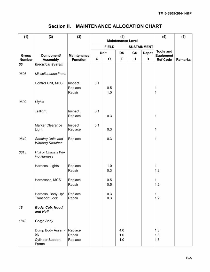
TM 5-3805-264-14&P
B-5
Section II. MAINTENANCE ALLOCATION CHART
(1) (2) (3) (4)Maintenance Level
(5) (6)
Group Number
Component/Assembly
Maintenance Function
Tools and Equipment Ref Code Remarks
FIELD SUSTAINMENT
Unit DS GS Depot
C O F H D06 Electrical System
0608 Miscellaneous Items
Control Unit, MCS Inspect 0.1Replace 0.5 1Repair 1.0 1
0609 Lights
Taillight Inspect 0.1Replace 0.3 1
Marker Clearance Light
InspectReplace
0.10.3 1
0610 Sending Units and Warning Switches
Replace 0.3 1
0613 Hull or Chassis Wir-ing Harness
Harness, Lights Replace 1.0 1Repair 0.3 1,2
Harnesses, MCS Replace 0.5 1Repair 0.5 1,2
Harness, Body Up/Transport Lock
ReplaceRepair
0.30.3
11,2
18 Body, Cab, Hood, and Hull
1810 Cargo Body
Dump Body Assem-bly
Replace 4.0 1,3Repair 1.0 1,3
Cylinder Support Frame
Replace 1.0 1,3

TM 5-3805-264-14&P
B-6
Section II. MAINTENANCE ALLOCATION CHART (Con’t)
(1) (2) (3) (4)Maintenance Level
(5) (6)
Group Number
Component/Assembly
Maintenance Function
Tools and Equipment Ref Code Remarks
FIELD SUSTAINMENT
Unit DS GS Depot
C O F H D1810 (Con’t)
Cargo Body
Tailgate, MCS Inspect 0.1Replace 1.0 1,2Repair 0.5 1,2
Air Cylinder, Tailgate Release
Replace 0.5 1Repair 0.8 1
Air Cylinder, MCS Replace 0.5 1Repair 1.0 1
Air Lines/Hoses Replace 0.5 1
22 Body, Chassis, and Hull Accessory Items
2201 Canvas, Rubber, or Plastic Items
Cargo Cover Inspect 0.1Replace 0.5 1Repair 0.5 3
Support Frame/Roll-ers
ReplaceRepair
0.70.7
11
Crank Assembly Replace 0.7 1Repair 1.0 1
2210 Data Plates and Instruction Holders
Replace 0.3 1

TM 5-3805-264-14&P
B-7
Section II. MAINTENANCE ALLOCATION CHART (Con’t)
(1) (2) (3) (4)Maintenance Level
(5) (6)
Group Number
Component/Assembly
Maintenance Function
Tools and Equipment Ref Code Remarks
FIELD SUSTAINMENT
Unit DS GS Depot
C O F H D24 Hydraulic and Fluid
Systems
2401 Pump and Motor
Hydraulic Pump Assembly
ReplaceRepair
1.01.0
1,31,3
2403 Hydraulic Controls and/or Manual Con-trols
Dump Control Assembly
ReplaceRepair
0.50.1
11
2406 Strainers, Filters, Lines, and Fittings
Filter Assembly Service 0.3 1Replace 0.5 1Repair 0.3 1
Hoses/Fittings Replace 0.3 1,2
2407 Hydraulic Cylinders
Cylinder Assembly Replace 2.0 1,3Repair 2.0 1,3,4,5,6,
2408 Liquid Tanks or Res-ervoirs
Reservoir Assembly Replace 0.5 1,2Repair 0.5 1

TM 5-3805-264-14&P
B-8
Section III. TOOLS AND TEST EQUIPMENT REQUIREMENTS
Section IV. REMARKS
None.
Tool or Test Equipment Reference
CodeMaintenance
Level NomenclatureNational Stock
Number Tool Number1 O, F,H Tool Kit, General Mechanic’s: Auto-
motiveSC 5180-90-CL-N26
5180-00-177-7033 W33004
2 O Shop Equipment, Automotive Main-tenance and Repair: Common No. 1, Less PowerSC 4910-95-CL-A74
4910-00-754-0654 W32593
3 F,H Shop Equipment, Automotive Main-tenance and Repair: Field Mainte-nance, Basic, Less PowerSC 4910-95-A31
4910-00-754-0705 T24660
SPECIAL TOOLS
4 F Installer, Seal: 3-Inch J42381
5 F Installer, Seal: 4-Inch J42382
6 F Installer, Seal: 5-Inch J42383

TM 5-3805-264-14&P
C-1
APPENDIX CREPAIR PARTS AND SPECIAL TOOLS LISTS (RPSTL)
Section I. INTRODUCTION
C-1. SCOPE.
This Repair Parts and Special Tools Lists (RPSTL) lists and authorizes spares and repair parts; specialtools; special test, measurement, and diagnostic equipment (TMDE); and other special support equipment requiredfor performance of Unit, Direct Support, and General Support Maintenance of the M917A1, M917A1 w/MCS,M917A2, and M917A2 w/MCS Dump Truck Body. It authorizes the requisitioning, issue, and disposition of spares,repair parts, and special tools as indicated by the Source, Maintenance and Recoverability (SMR) codes.
C-2. GENERAL.
In addition to Section I, Introduction, this RPSTL is divided into the following sections:a. Section II, Repair Parts List. A list of spares and repair parts authorized by this RPSTL for use in
the performance of maintenance. The list also includes parts which must be removed for replacement of the autho-rized parts. Parts lists are composed of functional groups in ascending alphanumeric sequence, with the parts ineach group listed in ascending figure and item number sequence. Bulk materials are listed by item name sequenceat the end of the section. Repair part kits are listed separately in their own functional group within Section II. Repairparts for reparable special tools are also listed in this section. Items listed are shown on the associated illustra-tion(s)/figure(s).
b. Section III, Special Tools List. A list of special tools, special TMDE, and other special supportequipment authorized by this RPSTL [as indicated by Basis of Issue (BOI) information in the DESCRIPTION ANDUSABLE ON CODE (UOC) column] for the performance of maintenance. Not applicable. Refer to TM 9-2320-363-24P.
c. Section IV, Cross-Reference Indexes. A list, in National Item Identification Number (NIIN)sequence, of all National stock numbered items appearing in the listing, followed by a list in alphanumericsequence of all part numbers appearing in the listings. National Stock Numbers (NSN) and part numbers are cross-referenced to each illustration/figure and item number appearance.
C-3. EXPLANATION OF COLUMNS (SECTIONS II AND III).
a. ITEM NO - Column (1). Indicates the number used to identify items called out in the illustration.b. SMR CODE - Column (2). The SMR code is a five-position code containing supply/requisitioning
information, maintenance category authorization criteria, and disposition instruction, as shown in the followingbreakout:
* Complete Repair: Maintenance capacity, capability, and authority to perform all corrective maintenance tasks of the “Repair” function in ause/user environment in order to restore serviceability to a failed item.
Source Code Maintenance Code Recoverability Code
XXxxx xxXXx xxxxX
1st two positions 3d position 4th position 5th position
How you get an item. Who can install, replace or use the item.
Who can do complete repair* on the item.
Who determines disposition action on an unserviceable item.

TM 5-3805-264-14&P
C-2
C-3. EXPLANATION OF COLUMNS (SECTIONS II AND III) (Con’t).
(1) Source Code. The source code tells you how to get an item needed for maintenance,repair, or overhaul of an end item/equipment. Explanations of source codes follow:
Code Application/Explanation
PAPBPC**PDPEPFPG
Stocked items; use the applicable NSN to request/requisition items with thesesource codes. They are authorized to the maintenance category indicated bythe code entered in the third position of the SMR code.
**Items coded PC are subject to deterioration.
. . . . . . . . . . . . . . . . . . . . . . . . . . . . . . . . . . . . . . . . . . . . . . . . . . . . . . . . . . .
KDKFKB
Items with these codes are not to be requested/requisitioned individually. Theyare part of a kit which is authorized to the maintenance category indicated inthe third position of the SMR code. The complete kit must be requisitioned andapplied. . . . . . . . . . . . . . . . . . . . . . . . . . . . . . . . . . . . . . . . . . . . . . . . . . . . . . . . . . . .
MO-
MF-
MH-ML-
MD-
Made at UM/AVUMLevelMade at DS/AVUMLevelMade at GS LevelMade at SpecializedRepair Activity (SRA)Made at Depot
Items with these codes are not to be requested/requisitioned individually. Theymust be made from bulk materiel which is identified by the part number in theDESCRIPTION AND USABLE ON CODE (UOC) column and listed in the bulkmateriel group of the repair parts list in this RPSTL. If the item is authorized toyou by the third position of the SMR code, but the source code indicates it ismade at a higher level, order the item from the higher level of maintenance.
. . . . . . . . . . . . . . . . . . . . . . . . . . . . . . . . . . . . . . . . . . . . . . . . . . . . . . . . . . .
AO-
AF-
AH-
ALAD
Assembled byUM/AVUM LevelAssembled byDS/AVUM LevelAssembled by GSLevelAssembled by SRAAssembled at Depot
Items with these codes are not to be requested/requisitioned individually. Theparts that make up the assembled item must be requisitioned or fabricatedand assembled at the level of maintenance indicated by the source code. Ifthe third position code of the SMR code authorizes you to replace the items,but the source code indicates that the item is assembled at a higher level,order the item from the higher level of maintenance

TM 5-3805-264-14&P
C-3
C-3. EXPLANATION OF COLUMNS (SECTIONS II AND III) (Con’t).
NOTECannibalization of controlled exchange, when authorized, may be used as a sourceof supply for items with the following source codes, except for those source coded"XA".Code Application/ExplanationXA. . . . . . . . . . . . . .DO NOT requisition an "XA"-coded item. Order its next higher assembly.XB. . . . . . . . . . . . . .In an "XB" item is not available from salvage, order it using the CAGEC
and part number given.XC. . . . . . . . . . . . . .Installation drawing, diagram, instruction sheet or field service drawing
that is identified by manufacturer's part number.XD. . . . . . . . . . . . . .Item is not stocked. Order an "XD"-coded item through normal supply
channels using the CAGEC and part number given, if no NSN is avail-able.
(2) Maintenance Code. Maintenance codes tell you the level(s) of maintenance authorized touse and repair support items. The maintenance codes are entered in the third and fourth positions of the SMRcode as follows:
(a) The maintenance code entered in the third position tells you the lowest maintenancelevel authorized to remove, replace, and use an item. The maintenance code entered in the third position will indi-cate authorization to one of the following levels of maintenance:
Code Application/ExplanationC . . . . . . . . . . . . . . .Operator or Crew Maintenance done within Unit Maintenance or aviation
unit maintenance.O. . . . . . . . . . . . . . .Unit Maintenance or aviation unit can remove, replace, and use the item.F . . . . . . . . . . . . . . .Direct Support Maintenance or aviation intermediate maintenance can
remove, replace, and use the item.H . . . . . . . . . . . . . . .General Support Maintenance can remove, replace, and use the item.L . . . . . . . . . . . . . . .Specialized Repair Activity (SRA) can remove, replace, and use the item.D . . . . . . . . . . . . . . .Depot Maintenance can remove, replace, and use the item.
NOTESome limited repair may be done on the item at a lower level of maintenance, ifauthorized by the Maintenance Allocation Chart (MAC) and SMR codes.
(b) The maintenance code entered in the fourth position tells whether or not the item is tobe repaired and identifies the lowest maintenance level with the capability to do complete repair (i.e., perform allauthorized “Repair” functions). The maintenance code in the fourth position will indicate authorization to one of thefollowing levels of maintenance:
Code Application/ExplanationO. . . . . . . . . . . . . . .Unit Maintenance or aviation unit maintenance is the lowest level that can
do complete repair of the item.F . . . . . . . . . . . . . . .Direct Support Maintenance or aviation intermediate maintenance is the
lowest level that can do complete repair of the item.

TM 5-3805-264-14&P
C-4
C-3. EXPLANATION OF COLUMNS (SECTIONS II AND III) (Con't).
Code Application/ExplanationH . . . . . . . . . . . . . . .General Support Maintenance is the lowest level that can do complete
repair of the item.L . . . . . . . . . . . . . . .Specialized Repair Activity (SRA) is the lowest level that can do complete
repair of the item.D . . . . . . . . . . . . . . .Depot Maintenance is the lowest level that can do complete repair of the
item.Z . . . . . . . . . . . . . . .Nonreparable. No repair is authorized.B . . . . . . . . . . . . . . .No repair is authorized. (No parts or special tools are authorized for the
maintenance of a "B"-coded item.) However, the item may be recondi-tioned by adjusting, lubricating, etc., at the user level.
(3) Recoverability Code. Recoverability codes are assigned to items to indicate the disposi-tion action on unserviceable items. The recoverability code is entered in the fifth position of the SMR code as fol-lows:
Code Application/ExplanationZ . . . . . . . . . . . . . . .Nonreparable item. When unserviceable, condemn and dispose of the
item at the level of maintenance shown in the third position of the SMRcode.
O. . . . . . . . . . . . . . .Reparable item. When uneconomically reparable, condemn and disposeof the item at Unit Maintenance or aviation unit maintenance.
F . . . . . . . . . . . . . . .Reparable item. When uneconomically reparable, condemn and disposeof the item at Direct Support Maintenance or aviation intermediate main-tenance.
H . . . . . . . . . . . . . . .Reparable item. When uneconomically reparable, condemn and disposeof the item at General Support Maintenance.
D . . . . . . . . . . . . . . .Reparable item. When beyond lower level repair capability, return toDepot Maintenance. Condemnation and disposal of item not authorizedbelow Depot Maintenance.
L . . . . . . . . . . . . . . .Reparable item. Condemnation and disposal of item not authorized belowSpecialized Repair Activity (SRA).
A . . . . . . . . . . . . . . .Item requires special handling or condemnation procedures because ofspecific reasons (e.g., precious metal content, high dollar value, critical material, or hazardous material). Refer to appropriate manuals/directivesfor specific instructions.
c. NSN - Column (3). Lists the National Stock Number assigned to the item. Use the NSN forrequests/requisitions.
d. CAGEC - Column (4). The Commercial and Government Entity (CAGE) Code (C) is a five-digitalphanumeric code which is used to identify the manufacturer, distributor, or Government agency, etc., that sup-plies the item.
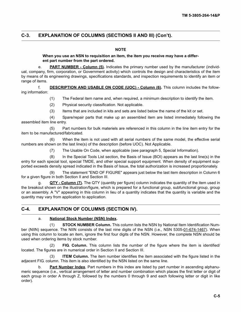
TM 5-3805-264-14&P
C-5
C-3. EXPLANATION OF COLUMNS (SECTIONS II AND III) (Con’t).
NOTEWhen you use an NSN to requisition an item, the item you receive may have a differ-ent part number from the part ordered.
e. PART NUMBER - Column (5). Indicates the primary number used by the manufacturer (individ-ual, company, firm, corporation, or Government activity) which controls the design and characteristics of the itemby means of its engineering drawings, specifications standards, and inspection requirements to identify an item orrange of items.
f. DESCRIPTION AND USABLE ON CODE (UOC) - Column (6). This column includes the follow-ing information:
(1) The Federal item name and, when required, a minimum description to identify the item.(2) Physical security classification. Not applicable.(3) Items that are included in kits and sets are listed below the name of the kit or set.(4) Spare/repair parts that make up an assembled item are listed immediately following the
assembled item line entry.(5) Part numbers for bulk materiels are referenced in this column in the line item entry for the
item to be manufactured/fabricated.(6) When the item is not used with all serial numbers of the same model, the effective serial
numbers are shown on the last line(s) of the description (before UOC). Not Applicable.(7) The Usable On Code, when applicable (see paragraph 5, Special Information).(8) In the Special Tools List section, the Basis of Issue (BOI) appears as the last line(s) in the
entry for each special tool, special TMDE, and other special support equipment. When density of equipment sup-ported exceeds density spread indicated in the Basis of Issue, the total authorization is increased proportionately.
(9) The statement "END OF FIGURE" appears just below the last item description in Column 6for a given figure in both Section II and Section III.
g. QTY - Column (7). The QTY (quantity per figure) column indicates the quantity of the item used inthe breakout shown on the illustration/figure, which is prepared for a functional group, subfunctional group, groupor an assembly. A "V" appearing in this column in lieu of a quantity indicates that the quantity is variable and thequantity may vary from application to application.
C-4. EXPLANATION OF COLUMNS (SECTION IV).
a. National Stock Number (NSN) Index. (1) STOCK NUMBER Column. This column lists the NSN by National Item Identification Num-
ber (NIIN) sequence. The NIIN consists of the last nine digits of the NSN (i.e., NSN 5305-01-674-1467). Whenusing this column to locate an item, ignore the first four digits of the NSN. However, the complete NSN should beused when ordering items by stock number.
(2) FIG. Column. This column lists the number of the figure where the item is identified/located. The figures are in numerical order in Section II and Section III.
(3) ITEM Column. The item number identifies the item associated with the figure listed in theadjacent FIG. column. This item is also identified by the NSN listed on the same line.
b. Part Number Index. Part numbers in this index are listed by part number in ascending alphanu-meric sequence (i.e., vertical arrangement of letter and number combination which places the first letter or digit ofeach group in order A through Z, followed by the numbers 0 through 9 and each following letter or digit in likeorder).

TM 5-3805-264-14&P
C-6
C-4. EXPLANATION OF COLUMNS (SECTION IV) (Con’t).
(1) CAGEC Column. The Commercial and Government Entity (CAGE) Code (C) is a five-digitalphanumeric code used to identify the manufacturer, distributor, or Government agency, etc., that supplies theitem.
(2) PART NUMBER Column. Indicates the primary number used by the manufacturer (individ-ual, firm, corporation, or Government activity) which controls the design and characteristics of the item by means ofits engineering drawings, specifications, standards, and inspection requirements to identify an item or range ofitems.
(3) STOCK NUMBER Column. This column lists the NSN for the associated part number andmanufacturer identified in the PART NUMBER and CAGEC columns to the left.
(4) FIG. Column. This column lists the number of the figure where the item is identified/locatedin Section II and Section III.
(5) ITEM Column. The item number assigned to the item as it appears in the figure referencedin the FIG. column.
C-5. SPECIAL INFORMATION.
a. Usable On Code. The Usable On Code appears in the lower left corner of the DESCRIPTION col-umn heading. Usable on codes are:
7A1 M917A17A2 M917A27E1 M917A1 w/MCS7E2 M917A2 w/MCS
b. Fabrication Instructions. Bulk materiels required to manufacture items are listed in the bulkmateriel functional group of this RPSTL. Part numbers for bulk materiels are also referenced in the Description col-umn of the line item entry for the item to be manufactured/fabricated. Detailed fabrication instructions for itemssource coded to be manufactured or fabricated are found in Appendix G.
c. Assembly Instructions. Detailed assembly instructions for items source coded to be assembledfrom component spare/repair parts are found in Chapters 4 and 5. Items that make up the assembly are listedimmediately following the assembly item entry or reference is made to an applicable figure.
d. Kits. Line item entries for repair kits appear in Group 9401 in Section II.e. Index Numbers. Items which have the word BULK in the FIG. column will have an index number
shown in the item column. This index number is a cross-reference between the National Stock Number Index, thePart Number Index, and the bulk materiel list in Section II.
f. Associated Publications. The publications listed below pertain to the M915 Family of Vehiclesand its components:
Publication Short TitleTM 9-2320-363-10 Operator’s Manual for M915 Family of VehiclesTM 9-2320-363-20 Unit Maintenance Manual for M915 Family of VehiclesTM 9-2320-363-34 Direct Support and General Support Maintenance Man-
ual for M915 Family of VehiclesTM 9-2320-363-24P Unit, Direct Support, and General Support RPSTL for
M915 Family of VehiclesTM 9-2320-302 Series M915 Family of Vehicles IETM

TM 5-3805-264-14&P
C-7
C-6. HOW TO LOCATE REPAIR PARTS.
a. When National Stock Number or Part Number is Not Known: (1) First. Using the Table of Contents, determine the assembly group or subassembly group to
which the item belongs. This is necessary since figures are prepared for assembly groups and subassemblygroups, and listings are divided into the same groups.
(2) Second. Find the figure covering the assembly group or subassembly group to which theitem belongs.
b. When National Stock Number or Part Number is Known: (1) First. Using the National Stock Number Index or Part Number Index, find the pertinent
NSN or part number. The NSN Index is in National Item Identification Number (NIIN) sequence [paragraph C-4a.(1)]. The part numbers in the Part Number Index are listed in ascending alphanumeric sequence (paragraph C-4b.). Both indexes cross-reference you to the illustration/figure and item number of the item you are looking for.
(2) Second. Turn to the figure and item number, verify that the item is the one you're lookingfor, then locate the item number in the repair parts list for the figure.
C-7. ABBREVIATIONS.
For standard abbreviations see MIL-STD-12D, Military Standard Abbreviations for Use on Drawings,Specifications, Standards, and in Technical Documents.
Abbreviations ExplanationNIIN . . . . . . . . . . . . . . . . . . . . . . . . . . . . National Item Identification Number (consists of the last 9
digits of the NSN)RPSTL . . . . . . . . . . . . . . . . . . . . . . . . . . Repair Parts and Special Tools Lists

SECTION II TM 5-3805-264-14&P
Figure 1. Control Unit Assembly, MCS.
9
8
10
7 6
5
5
5
23
3
1
2-10
4
5-10
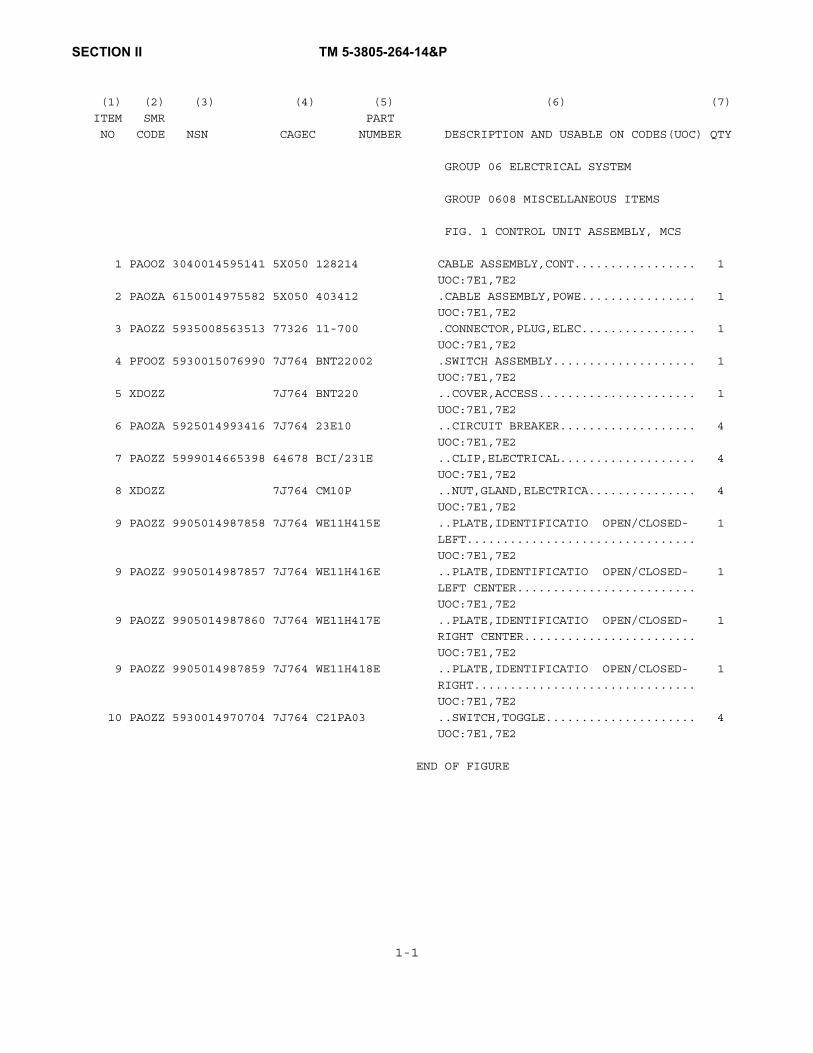
SECTION II TM 5-3805-264-14&P
(1) (2) (3) (4) (5) (6) (7)
ITEM SMR PART
NO CODE NSN CAGEC NUMBER DESCRIPTION AND USABLE ON CODES(UOC) QTY
GROUP 06 ELECTRICAL SYSTEM
GROUP 0608 MISCELLANEOUS ITEMS
FIG. 1 CONTROL UNIT ASSEMBLY, MCS
1 PAOOZ 3040014595141 5X050 128214 CABLE ASSEMBLY,CONT................. 1
UOC:7E1,7E2
2 PAOZA 6150014975582 5X050 403412 .CABLE ASSEMBLY,POWE................ 1
UOC:7E1,7E2
3 PAOZZ 5935008563513 77326 11-700 .CONNECTOR,PLUG,ELEC................ 1
UOC:7E1,7E2
4 PFOOZ 5930015076990 7J764 BNT22002 .SWITCH ASSEMBLY.................... 1
UOC:7E1,7E2
5 XDOZZ 7J764 BNT220 ..COVER,ACCESS...................... 1
UOC:7E1,7E2
6 PAOZA 5925014993416 7J764 23E10 ..CIRCUIT BREAKER................... 4
UOC:7E1,7E2
7 PAOZZ 5999014665398 64678 BCI/231E ..CLIP,ELECTRICAL................... 4
UOC:7E1,7E2
8 XDOZZ 7J764 CM10P ..NUT,GLAND,ELECTRICA............... 4
UOC:7E1,7E2
9 PAOZZ 9905014987858 7J764 WE11H415E ..PLATE,IDENTIFICATIO OPEN/CLOSED- 1
LEFT................................
UOC:7E1,7E2
9 PAOZZ 9905014987857 7J764 WE11H416E ..PLATE,IDENTIFICATIO OPEN/CLOSED- 1
LEFT CENTER.........................
UOC:7E1,7E2
9 PAOZZ 9905014987860 7J764 WE11H417E ..PLATE,IDENTIFICATIO OPEN/CLOSED- 1
RIGHT CENTER........................
UOC:7E1,7E2
9 PAOZZ 9905014987859 7J764 WE11H418E ..PLATE,IDENTIFICATIO OPEN/CLOSED- 1
RIGHT...............................
UOC:7E1,7E2
10 PAOZZ 5930014970704 7J764 C21PA03 ..SWITCH,TOGGLE..................... 4
UOC:7E1,7E2
END OF FIGURE
1-1

SECTION II TM 5-3805-264-14&P
Figure 2. Control Switches, MCS.
5
42
6
1
2
3
2
2
2
26
7E1
7E2

SECTION II TM 5-3805-264-14&P
(1) (2) (3) (4) (5) (6) (7)
ITEM SMR PART
NO CODE NSN CAGEC NUMBER DESCRIPTION AND USABLE ON CODES(UOC) QTY
GROUP 0608 MISCELLANEOUS ITEMS
FIG. 2 CONTROL SWITCHES, MCS
1 XDOZZ 64678 06-24618-000 BRACKET,SWITCH PANE................. 1
UOC:7A1,7E1
2 PAOZA 5930013320680 64678 681 545 07 22 SWITCH,TOGGLE....................... 4
UOC:7A1,7E1
2 PFOZZ 5930015204456 64678 A06-30769-101 SWITCH,TOGGLE....................... 4
UOC:7E2
3 XDOZZ 64678 24-00783-000 4X-MAT'L CTRL LABLE................. 1
UOC:7A1,7E1
4 PFOZZ 5305014667940 64678 23-10864-706 SCREW,MACHINE 1/4-20 X 0.75 IN..... 4
UOC:7A1,7E1
5 PAOZZ 5310003470021 99321 3507 WASHER,FLAT 1/4"................... 4
UOC:7A1,7E1
6 PAOZA 6220014695480 64678 06-22309-048 LIGHT,INDICATOR MATERIAL CONTROL... 1
UOC:7A1,7E1,7E2
END OF FIGURE
2-1

SECTION II TM 5-3805-264-14&P
Figure 3. Taillights, Marker Lights and Reflectors.

SECTION II TM 5-3805-264-14&P
(1) (2) (3) (4) (5) (6) (7)
ITEM SMR PART
NO CODE NSN CAGEC NUMBER DESCRIPTION AND USABLE ON CODES(UOC) QTY
GROUP 0609 LIGHTS
FIG. 3 TAILLIGHTS, MARKER LIGHTS AND
REFLECTORS
1 PAOZZ 6220010865691 13548 60202R STOP LIGHT-TAILLIGH STOP/TURN/TAIL 2
LIGHT ASSY..........................
UOC:7A1,7E1
1 PAOZA 6220015186827 13548 60085R LAMP UNIT,VEHICULAR................. 2
UOC:7A2,7E2
2 PAOZZ 5325011636558 13548 60700 GROMMET,NONMETALLIC................. 2
3 PAOZZ 5325012833513 12662 142-18 GROMMET............................. 5
4 PAOZA 6240015186843 13548 10250R LAMP,INCANDESCENT................... 5
UOC:7A2,7E2
4 PAOZZ 6220010950011 13548 10004R LIGHT,MARKER,CLEARA................. 5
UOC:7A1,7E1
5 PAOZZ 6220014459978 12662 B490A REFLECTOR,LIGHT AMBER.............. 4
6 PAOZZ 6220014459981 12662 B490R REFLECTOR,LIGHT RED................ 2
7 PFOZZ 5340014457781 5X050 238021 BRACKET,ANGLE....................... 1
8 PAOZZ 5935015183692 13548 93745 CONNECTOR ASSEMBLY,................. 5
UOC:7A2,7E2
9 PAOZZ 5935015183690 13548 94706 CONNECTOR ASSEMBLY,................. 2
UOC:7A2,7E2
END OF FIGURE
3-1

SECTION II TM 5-3805-264-14&P
Figure 4. Wiring Harness, Beacon Light.
2
34
56
7
8
9
10
11
2-11
1

SECTION II TM 5-3805-264-14&P
(1) (2) (3) (4) (5) (6) (7)
ITEM SMR PART
NO CODE NSN CAGEC NUMBER DESCRIPTION AND USABLE ON CODES(UOC) QTY
GROUP 0609 LIGHTS
FIG. 4 WIRING HARNESS, BEACON LIGHT
1 PAOOO 6150014459130 5X050 403255 WIRING HARNESS,BRAN BEACON LIGHT... 1
2 PAOZZ 5935013087866 77060 15300027 .CONNECTOR BODY,PLUG................ 1
3 PAOZZ 5940014697988 77060 12129493 .TERMINAL,STUD...................... 2
4 PAOZZ 5975012268078 77060 12010293 .BOOT,DUST AND MOIST................ 2
5 PAOZZ 5975012304370 5A910 8338566 .CABLE NIPPLE,ELECTR................ 1
6 PAOZZ 5310008338567 19207 8338567 .WASHER,SLOTTED..................... 1
7 PAOZA 5999000572929 19204 572929 .CONTACT,ELECTRICAL NO. 14 WIRE 1
GAGE................................
8 PAOZZ 5940003996676 19207 8338564 .TERMINAL SET,QUICK................. 1
9 PAOZZ 5970008338562 19207 8338562 .INSULATOR,BUSHING.................. 1
10 PAOZZ 5935008338561 19207 8338561 .SHELL,ELECTRICAL CO................ 1
11 PAOZZ 5940014621718 77060 15300014 .TERMINAL,LUG....................... 1
END OF FIGURE
4-1

SECTION II TM 5-3805-264-14&P
Figure 5. Bodyup and Transport Lock Switches.
12 3

SECTION II TM 5-3805-264-14&P
(1) (2) (3) (4) (5) (6) (7)
ITEM SMR PART
NO CODE NSN CAGEC NUMBER DESCRIPTION AND USABLE ON CODES(UOC) QTY
GROUP 0610 SENDING UNITS AND WARNING
SWITCHES
FIG. 5 BODYUP AND TRANSPORT LOCK
SWITCHES
1 PAOZZ 5305009897434 96906 MS35207-263 SCREW,MACHINE 10-32X0.50........... 2
2 PAOZA 5930013360919 13445 8486 SWITCH,LEVER........................ 1
3 PAOZZ 5930014460980 5X050 129871 SWITCH,PUSH-PULL TRAVEL LOCK SWITCH 1
END OF FIGURE
5-1

SECTION II TM 5-3805-264-14&P
Figure 6. Wiring Harness, Dump Body Lights.
5
6
4
3
2A
1
2-6
1
DETAIL A

SECTION II TM 5-3805-264-14&P
(1) (2) (3) (4) (5) (6) (7)
ITEM SMR PART
NO CODE NSN CAGEC NUMBER DESCRIPTION AND USABLE ON CODES(UOC) QTY
GROUP 0613 HULL OR CHASSIS WIRING
HARNESS
FIG. 6 WIRING HARNESS, DUMP BODY
LIGHTS
1 PAOZZ 6150014466345 5X050 403254 CABLE ASSEMBLY,SPEC DUMP BODY 1
LIGHTS..............................
2 XDOZZ 77060 12084673 .LOCK,SECONDARY..................... 1
3 PAOZZ 5975013105011 77060 12015323 .BOOT,DUST AND MOIST................ 4
4 PAOZZ 5935013399574 77060 1201 0300 .PLUG,END SEAL,ELECT................ 1
5 XDOZZ 77060 12085036 .CONNECTOR,HOUSING.................. 1
6 PAOZZ 5940014621717 77060 12048159 .TERMINAL,LUG....................... 4
END OF FIGURE
6-1

SECTION II TM 5-3805-264-14&P
Figure 7. MCS Gate Harness and MCS Power Harness.
2 3
14
5
910
117
68
5
4
11
910
12
15
16
17 18
1314
2120
19
2-8 13-18
1 12

SECTION II TM 5-3805-264-14&P
(1) (2) (3) (4) (5) (6) (7)
ITEM SMR PART
NO CODE NSN CAGEC NUMBER DESCRIPTION AND USABLE ON CODES(UOC) QTY
GROUP 0613 HULL OR CHASSIS WIRING
HARNESS FIG. 7 MCS GATE HARNESS AND MCS
POWER HARNESS 1 PAOOA 6150014974886 5X050 403484 WIRING HARNESS,BRAN................. 1
UOC:7E1,7E2
2 PAOZZ 5935008563513 77326 11-700 .CONNECTOR,PLUG,ELEC................ 1
UOC:7E1,7E2
3 XDOZZ 77326 11-763 .SPRING,HELICAL,COMP................ 1
UOC:7E1,7E2
4 PAOZZ 5975013556985 77326 11-761 .BOOT,DUST AND MOIST................ 2
UOC:7E1,7E2
5 PAOZZ 5935001534397 77326 11-720 .CONNECTOR,RECEPTACL................ 2
UOC:7E1,7E2
6 PAOZZ 5975013105011 77060 12015323 .BOOT,DUST AND MOIST................ 8
UOC:7E1,7E2
7 PAOZZ 5999014229740 19207 12420936 .CONTACT,ELECTRICAL................. 8
UOC:7E1,7E2
8 PAOZZ 5935012145259 77060 12015792 .CONNECTOR BODY,PLUG................ 4
UOC:7E1,7E2
9 PAOZZ 5305000680508 80204 B1821BH025C075N SCREW,CAP,HEXAGON H 1/4-20X0.75.... 4
UOC:7A1,7E1,7E2
10 PAOZZ 5310008238804 96906 MS27183-9 WASHER,FLAT 1/4.................... 4
UOC:7A1,7E1,7E2
11 PAOZZ 5310000614650 45152 114356A NUT,SELF-LOCKING,HE 1/4-20......... 4
UOC:7A1,7E1,7E2
12 PAOOA 6150014974879 5X050 403248 CABLE ASSEMBLY,SPEC................. 1
UOC:7A1,7E1,7E2
13 PAOZZ 5935001534397 77326 11-720 .CONNECTOR,RECEPTACL................ 1
UOC:7A1,7E1,7E2
14 PAOZZ 5975013556985 77326 11-761 .BOOT,DUST AND MOIST................ 1
UOC:7A1,7E1,7E2
15 XDOZZ 77060 12066304 .CONNECTOR,LOCKING.................. 1
UOC:7A1,7E1,7E2
16 PFOZZ 2530014649916 77060 1204 8086 .BOOT,VEHICULAR COMP................ 7
UOC:7A1,7E1,7E2
17 PAOZZ 5940013661563 77060 12048074 .TERMINAL,QUICK DISC................ 7
UOC:7A1,7E1,7E2
18 XDOZZ 77060 1204 7938 .CONNECTOR,PLUG,ELEC................ 1
UOC:7A1,7E1,7E2
19 PAOZZ 5310000614650 45152 114356A NUT,SELF-LOCKING,HE................. 2
UOC:7A1,7E1,7E2
20 PAOZZ 5310008238804 96906 MS27183-9 WASHER,FLAT......................... 2
UOC:7A1,7E1,7E2
21 PAOZZ 5305000680508 80204 B1821BH025C075N SCREW,CAP,HEXAGON H................. 2
UOC:7A1,7E1,7E2 END OF FIGURE
7-1

SECTION II TM 5-3805-264-14&P
Figure 8. Bodyup/Transport Lock Harness and Material Control Chassis Harness.
2-4
1
1
2
3
4
6
6-14
5
1
14
78
13
910
11
12
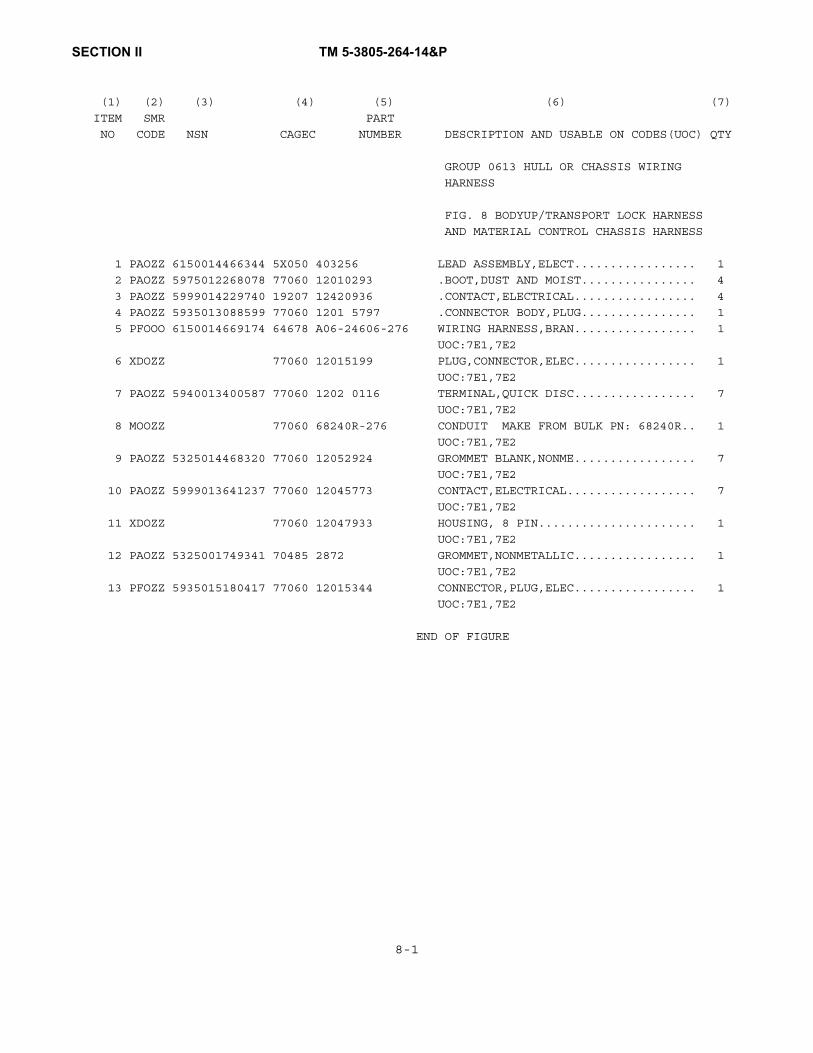
SECTION II TM 5-3805-264-14&P
(1) (2) (3) (4) (5) (6) (7)
ITEM SMR PART
NO CODE NSN CAGEC NUMBER DESCRIPTION AND USABLE ON CODES(UOC) QTY
GROUP 0613 HULL OR CHASSIS WIRING
HARNESS
FIG. 8 BODYUP/TRANSPORT LOCK HARNESS
AND MATERIAL CONTROL CHASSIS HARNESS
1 PAOZZ 6150014466344 5X050 403256 LEAD ASSEMBLY,ELECT................. 1
2 PAOZZ 5975012268078 77060 12010293 .BOOT,DUST AND MOIST................ 4
3 PAOZZ 5999014229740 19207 12420936 .CONTACT,ELECTRICAL................. 4
4 PAOZZ 5935013088599 77060 1201 5797 .CONNECTOR BODY,PLUG................ 1
5 PFOOO 6150014669174 64678 A06-24606-276 WIRING HARNESS,BRAN................. 1
UOC:7E1,7E2
6 XDOZZ 77060 12015199 PLUG,CONNECTOR,ELEC................. 1
UOC:7E1,7E2
7 PAOZZ 5940013400587 77060 1202 0116 TERMINAL,QUICK DISC................. 7
UOC:7E1,7E2
8 MOOZZ 77060 68240R-276 CONDUIT MAKE FROM BULK PN: 68240R.. 1
UOC:7E1,7E2
9 PAOZZ 5325014468320 77060 12052924 GROMMET BLANK,NONME................. 7
UOC:7E1,7E2
10 PAOZZ 5999013641237 77060 12045773 CONTACT,ELECTRICAL.................. 7
UOC:7E1,7E2
11 XDOZZ 77060 12047933 HOUSING, 8 PIN...................... 1
UOC:7E1,7E2
12 PAOZZ 5325001749341 70485 2872 GROMMET,NONMETALLIC................. 1
UOC:7E1,7E2
13 PFOZZ 5935015180417 77060 12015344 CONNECTOR,PLUG,ELEC................. 1
UOC:7E1,7E2
END OF FIGURE
8-1

SECTION II TM 5-3805-264-14&P
Figure 9. Cylinder Support Frame and Brackets.
1 2
3
4
45
6
2
27
4
8
9 10
11

SECTION II TM 5-3805-264-14&P
(1) (2) (3) (4) (5) (6) (7)
ITEM SMR PART
NO CODE NSN CAGEC NUMBER DESCRIPTION AND USABLE ON CODES(UOC) QTY
GROUP 18 BODY, CAB, HOOD, AND HULL
GROUP 1810 CARGO BODY
FIG. 9 CYLINDER SUPPORT FRAME AND
BRACKETS
1 XDFZZ 5X050 128129 COVER ASSY,UPPER.................... 1
2 PAFZZ 5310000614651 19207 12387349-43 NUT,SELF-LOCKING,HE 5/8-11......... 30
3 PFFZZ 5340014459486 5X050 128130 BRACKET,MOUNTING L.H............... 1
4 PAFZZ 5305007247222 80204 B1821BH063C200N SCREW,CAP,HEXAGON H 5/8-11X2.0..... 30
5 XDFZZ 5X050 126617 CRADLE ASSEMBLY..................... 1
6 XDFZZ 5X050 237386 BRACKET,ANGLE,LH L.H............... 1
7 XDFZZ 5X050 237387 BRACKET,ANGLE,RH R.H............... 1
8 PFFZZ 5315014463121 5X050 208047 PIN,SHOULDER,HEADLE................. 1
9 PAFZZ 5305000712076 80204 B1821BH050C325N SCREW,CAP,HEXAGON H 1/2-13X3.25.... 1
10 PAFZZ 5310004883889 96906 MS51943-39 NUT,SELF-LOCKING,HE 1/2-13......... 1
11 PFFZZ 5340014495470 5X050 128131 BRACKET,MOUNTING R.H............... 1
END OF FIGURE
9-1
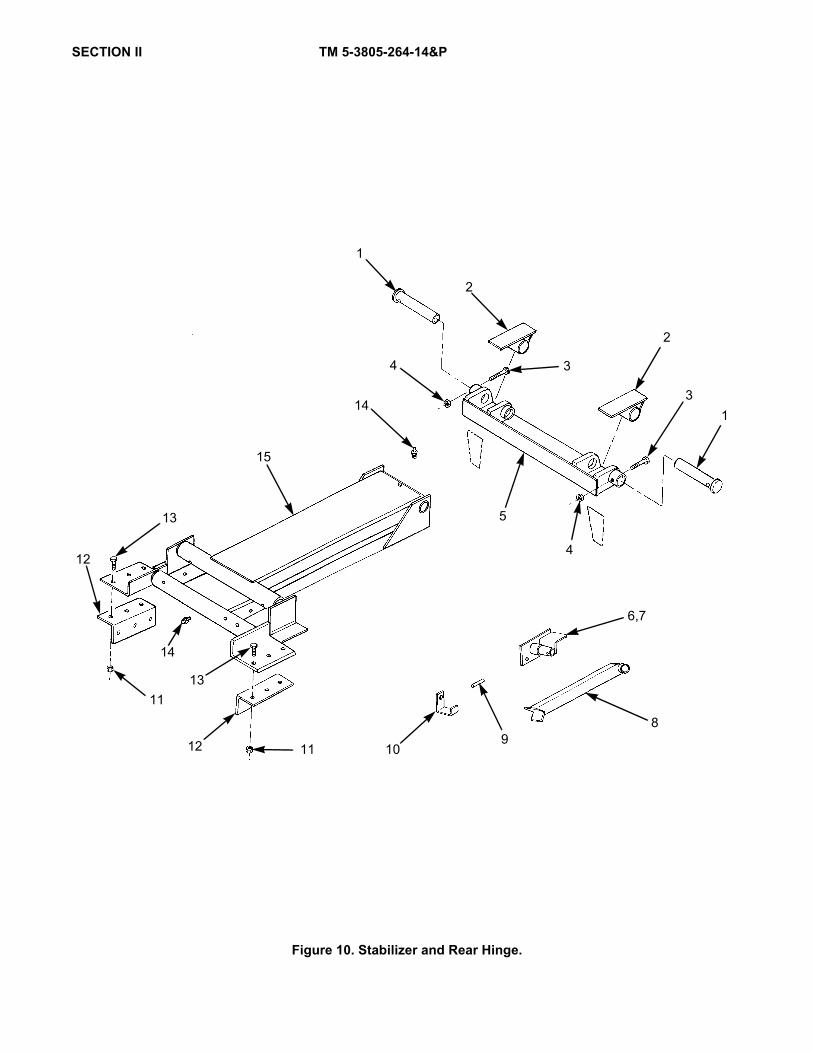
SECTION II TM 5-3805-264-14&P
Figure 10. Stabilizer and Rear Hinge.
13
15
12
11
14
13
12 11
5
4
14
6,7
109
8
31
2
3
2
1
4

SECTION II TM 5-3805-264-14&P
(1) (2) (3) (4) (5) (6) (7)
ITEM SMR PART
NO CODE NSN CAGEC NUMBER DESCRIPTION AND USABLE ON CODES(UOC) QTY
GROUP 1810 CARGO BODY
FIG. 10 STABILIZER AND REAR HINGE
1 PFFZZ 5315014470480 5X050 127170 PIN,STRAIGHT,HEADED................. 2
2 XDFZZ 5X050 110543 HINGE ASSY,UPPER.................... 2
3 PAFZZ 5305009474358 80204 B1821BH075C400N SCREW,CAP,HEXAGON H 3/4-10X4.00.... 2
4 PAFZZ 5310004093333 96906 MS51943-45 NUT,SELF-LOCKING,HE 3/4-10......... 2
5 XDFZZ 5X050 128125 HINGE ASSY,LOWER.................... 1
6 XDOZZ 5X050 129305 PIVOT ASSY,LH L.H.................. 1
7 XDOZZ 5X050 129306 PIVOT ASSY,RH R.H.................. 1
8 PGOZZ 2510014461842 5X050 128126 LEG,PROP,BODY....................... 2
9 PAOZZ 5315007218370 80205 NAS561-8-48 PIN,SPRING 1/4X3.00................ 2
10 XDOZZ 5X050 239693 BRACKET,SUPPORT..................... 2
11 PAFZZ 5310000614651 19207 12387349-43 NUT,SELF-LOCKING,HE 5/8-11......... 12
12 XDFZZ 5X050 239694 BRACKET,ANGLE....................... 2
13 PAFZZ 5305007247222 80204 B1821BH063C200N SCREW,CAP,HEXAGON H 5/8-11X2.00.... 12
14 PAOZZ 4730000504208 81343 AS15003-1 FITTING,LUBRICATION 1/8 NPT........ 5
15 XDFZZ 5X050 127838 STABILIZER ASSY..................... 1
END OF FIGURE
10-1

SECTION II TM 5-3805-264-14&P
Figure 11. Dump Body Assembly.
17
16 15
14
13
12
3
18 19
11
10
7
6 9
5
204
3
2
31
4
3
3
2
8
6-10
5

SECTION II TM 5-3805-264-14&P,C1
(1) (2) (3) (4) (5) (6) (7) ITEM SMR PART NO CODE NSN CAGEC NUMBER DESCRIPTION AND USABLE ON CODES(UOC) QTY GROUP 1810 CARGO BODY FIG. 11 DUMP BODY ASSEMBLY 1 XDOZZ 5X050 129568 CABSHIELD ASSEMBLY.................. 1 2 PAOZZ 5305007247222 80204 B1821BH063C200N SCREW,CAP,HEXAGON H 5/8-11 X 2.00.. 14 3 PAOZZ 5310000039174 81348 FFW92 WASHER,FLAT 5/8.................... 28 4 PAOZZ 5310000614651 19207 12387349-43 NUT,SELF-LOCKING,HE 5/8-11......... 14 5 XDFFF 5X050 126426 DUMP BOX W/STD GATE................. 1 UOC:7A1,7A2 5 XDFFF 5X050 143893 DUMP BOX W/STD GATE................. 1 5 XDFFF 5X050 126427 DUMP BOX W/MCS GATE WITH MCS GATE.. 1 UOC:7E1,7E2 6 PFOZZ 5340014696693 5X050 127373 .COVER,ACCESS....................... 1 7 PAOZZ 5305011622358 45152 1354190 .SCREW,TAPPING 5/16X3/4............ 4 8 PAOZZ 5315014470479 0PXJ7 63-04 .PIN,COTTER......................... 2 9 PAOZZ 5315014470481 5X050 117122 .PIN,SHOULDER,HEADLE................ 2 10 XDOZZ 5X050 127892 .TAILGATE ASSEMBLY STANDARD........ 1 UOC:7A1,7A2 11 PAOZZ 5340014465137 5X050 127852 PLATE,MOUNTING...................... 2 12 PAOZZ 5340014464927 5X050 237409 PLATE,MOUNTING...................... 2 13 PAOZZ 5305007252317 80204 B1821BH038C150N SCREW,CAP,HEXAGON H 3/8-16X1.50.... 12 14 PAOZZ 5340014460947 5X050 129732 PLATE,MOUNTING...................... 2 * 15 PAOZZ 64670 407023 GUARD,SPLASH,VEHICU................. 2 16 XDOZZ 5X050 245352 PLATE,ANCHOR,FLAP................... 2 17 PAOZZ 5310009359021 96906 MS51943-35 NUT,SELF-LOCKING,HE 3/8-16......... 12 18 PAOZZ 5315008098786 80205 MS16562-51 PIN,SPRING 3/16X1.25............... 4 19 PAOZZ 3040014462413 5X050 237410 SHAFT,STRAIGHT...................... 2 20 MOOZZ 5X050 403345X148.75 SIDEBOARD 2.0 X 8.0 X 148.75 IN, 2 MAKE FROM BULK PN: MILL2037 (81349). END OF FIGURE
11-1

SECTION II TM 5-3805-264-14&P
Figure 12. MCS Tailgate Assembly.
6
89
310
11
12
13
14
5
7432
2-15
1
15

SECTION II TM 5-3805-264-14&P
(1) (2) (3) (4) (5) (6) (7)
ITEM SMR PART
NO CODE NSN CAGEC NUMBER DESCRIPTION AND USABLE ON CODES(UOC) QTY
GROUP 1810 CARGO BODY
FIG. 12 MCS TAILGATE ASSEMBLY
1 PDOOO 2510014738251 5X050 140409 MCS TAILGATE,GREEN MCS TYPE - GREEN 1
UOC:7E1,7E2
1 PDOOO 2510014738250 5X050 140410 MCS TAILGATE,TAN MCS TYPE - TAN.... 1
UOC:7E1,7E2
2 XDOZZ 5X050 129652 .TAILGATE BARE MCS GATE............ 1
UOC:7E1,7E2
3 PAOZZ 5310004883889 96906 MS51943-39 .NUT,SELF-LOCKING,HE 1/2-13........ 8
UOC:7E1,7E2
4 PAOZZ 5305000712071 80204 B1821BH050C200N .SCREW,CAP,HEXAGON H 1/2-13X2.00... 4
UOC:7E1,7E2
5 XDOZZ 5X050 239974 .TUBE,METALLIC...................... 4
UOC:7E1,7E2
6 PAOZZ 4710014975644 5X050 239973 .TUBE,METALLIC...................... 4
UOC:7E1,7E2
7 PAOZZ 5306002264827 80204 B1821BH031C100N .BOLT,MACHINE 5/16-18 X 1.00....... 10
UOC:7E1,7E2
8 PFOZZ 5340014978124 5X050 129653 .COVER,ACCESS....................... 1
UOC:7E1,7E2
9 PAOZZ 5305000712076 80204 B1821BH050C325N .SCREW,CAP,HEXAGON H 1/2-13X3.25... 4
UOC:7E1,7E2
10 XDOZZ 5X050 129528 .GATE,MCS........................... 4
UOC:7E1,7E2
11 PFOZZ 3040014970345 5X050 239963 .BRACKET,EYE,ROTATIN................ 8
UOC:7E1,7E2
12 PAOZZ 5310008206653 52793 CW7435-57C .WASHER,LOCK 5/8................... 16
UOC:7E1,7E2
13 PAOZZ 5305007247228 80204 B1821BH063C300N .SCREW,CAP,HEXAGON H 5/8-11X3.00... 16
UOC:7E1,7E2
14 PAOZZ 5315015070537 50620 38-22LP .PIN,STRAIGHT,HEADED 3/8 X 2-1/2 4
IN. SQ. SPRING......................
15 PFOZZ 5310015187454 5X050 CMG 400892 WASHER,FLAT 5/16................... 10
UOC:7E1,7E2
END OF FIGURE
12-1

SECTION II TM 5-3805-264-14&P
Figure 13. Air Cylinder Assembly.
4-39
3
18
14
1312
1110
9
8
7
6
54
1
19
32-39
20
2
13
15 16
17
9
2021
2223
24 25
4443
2
40
2726
42
41
40
31
323334
3635
28 29
30
37 38 39
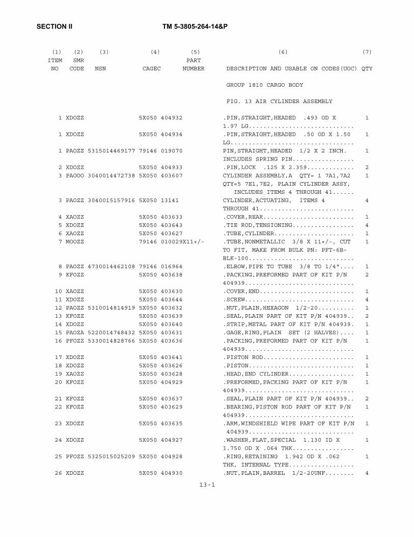
SECTION II TM 5-3805-264-14&P
(1) (2) (3) (4) (5) (6) (7)
ITEM SMR PART
NO CODE NSN CAGEC NUMBER DESCRIPTION AND USABLE ON CODES(UOC) QTY GROUP 1810 CARGO BODY FIG. 13 AIR CYLINDER ASSEMBLY 1 XDOZZ 5X050 404932 .PIN,STRAIGHT,HEADED .493 OD X 1
1.97 LG.............................
1 XDOZZ 5X050 404934 .PIN,STRAIGHT,HEADED .50 OD X 1.50 1
LG..................................
1 PAOZZ 5315014469177 79146 019070 PIN,STRAIGHT,HEADED 1/2 X 2 INCH. 1
INCLUDES SPRING PIN.................
2 XDOZZ 5X050 404933 .PIN,LOCK .125 X 2.359............. 2
3 PAOOO 3040014472738 5X050 403607 CYLINDER ASSEMBLY,A QTY= 1 7A1,7A2 1
QTY=5 7E1,7E2, PLAIN CYLINDER ASSY,
INCLUDES ITEMS 4 THROUGH 41......
3 PAOZZ 3040015157916 5X050 13141 CYLINDER,ACTUATING, ITEMS 4 4
THROUGH 41..........................
4 XAOZZ 5X050 403633 .COVER,REAR......................... 1
5 XDOZZ 5X050 403643 .TIE ROD,TENSIONING................. 4
6 XAOZZ 5X050 403627 .TUBE,CYLINDER...................... 1
7 MOOZZ 79146 010029X11+/- .TUBE,NONMETALLIC 3/8 X 11+/-, CUT 1
TO FIT, MAKE FROM BULK PN: PFT-6B-
BLK-100.............................
8 PAOZZ 4730014462108 79146 016964 .ELBOW,PIPE TO TUBE 3/8 TO 1/4".... 1
9 KFOZZ 5X050 403638 .PACKING,PREFORMED PART OF KIT P/N 2
404939..............................
10 XAOZZ 5X050 403630 .COVER,END.......................... 1
11 XDOZZ 5X050 403644 .SCREW.............................. 4
12 PAOZZ 5310014814919 5X050 403632 .NUT,PLAIN,HEXAGON 1/2-20.......... 1
13 KFOZZ 5X050 403639 .SEAL,PLAIN PART OF KIT P/N 404939.. 2
14 XDOZZ 5X050 403640 .STRIP,METAL PART OF KIT P/N 404939. 1
15 PAOZA 5220014748432 5X050 403631 .GAGE,RING,PLAIN SET (2 HALVES).... 1
16 PFOZZ 5330014828766 5X050 403636 .PACKING,PREFORMED PART OF KIT P/N 1
404939..............................
17 XDOZZ 5X050 403641 .PISTON ROD......................... 1
18 XDOZZ 5X050 403626 .PISTON............................. 1
19 XAOZZ 5X050 403628 .HEAD,END CYLINDER.................. 1
20 KFOZZ 5X050 404929 .PREFORMED,PACKING PART OF KIT P/N 1
404939..............................
21 KFOZZ 5X050 403637 .SEAL,PLAIN PART OF KIT P/N 404939.. 2
22 KFOZZ 5X050 403629 .BEARING,PISTON ROD PART OF KIT P/N 1
404939..............................
23 XDOZZ 5X050 403635 .ARM,WINDSHIELD WIPE PART OF KIT P/N 1
404939.............................
24 XDOZZ 5X050 404927 .WASHER,FLAT,SPECIAL 1.130 ID X 1
1.750 OD X .064 THK.................
25 PFOZZ 5325015025209 5X050 404928 .RING,RETAINING 1.942 OD X .062 1
THK, INTERNAL TYPE..................
26 XDOZZ 5X050 404930 .NUT,PLAIN,BARREL 1/2-20UNF........ 4
13-1

SECTION II TM 5-3805-264-14&P
(1) (2) (3) (4) (5) (6) (7)
ITEM SMR PART
NO CODE NSN CAGEC NUMBER DESCRIPTION AND USABLE ON CODES(UOC) QTY
27 PFOZZ 5310015022940 5X050 404931 .WASHER,LOCK 1/2".................. 4
28 PAOZZ 4730013456065 93061 VS209P-8-4 .BUSHING,PIPE 1/2-14 X 1/4-18 NPTF, 2
QTY 1 FOR CYLINDER PN: 131341, QTY
2 FOR CYLINDER PN: 403607...........
29 PAOZZ 4730001377875 30780 2101-4-4C .ELBOW,PIPE 0.25 IN................ 1
30 XDOZZ 79146 012037 .ADAPTER,STRAIGHT,PI 3/8X1/4 IN.... 2
30 PAOZZ 4730014551068 93061 68PMT-6-4 .ADAPTER,STRAIGHT,PI................ 1
31 KFOOO 5X050 403645 .VALVE,REGULATING,FL PART OF KIT P/N 1
404940.............................
32 PAOZA 5330014742447 5X050 403650 ..GASKET............................ 1
33 PAOZZ 5365014752277 5X050 403649 ..SPACER,PLATE...................... 1
34 PAOZA 5330014732903 5X050 403648 ..GASKET............................ 1
35 KFOZZ 5X050 403647 ..VALVE,PILOT ASSY PART OF KIT P/N 1
404940..............................
36 XDOZZ 5X050 403646 ..SCREW,SOCKET HEAD 0.50MM X 25.4MM 2
37 PAOZZ 5975013105011 77060 12015323 .BOOT,DUST AND MOIST................ 2
38 PAOZA 5999014064110 77060 12124582 .CONTACT,ELECTRICAL................. 2
39 PAOZZ 5935012144163 22785 12010973 .CONNECTOR BODY,PLUG................ 1
40 XDOZZ 79146 030084 .FILTER,ELEMENT,AIR................. 2
41 XDOZZ 93061 404938 .ELBOW,PIPE TO TUBE 1/2" NPT....... 1
42 XDOZZ 5X050 403642 NUT, JAM 5/8-18.................... 1
43 XDOZZ 5X050 403634 CLEVIS,ROD END...................... 1
44 PAOZZ 5315014469174 79146 019067. PIN,STRAIGHT,HEADED 1/2 X 1-11/32 1
IN. INCLUDES SPRING PIN 1/8 X 2 1/4
IN..................................
END OF FIGURE
13-2/13-3 Blank


SECTION II TM 5-3805-264-14&P
Figure 14. Air Tank, Lines and Fittings.
123
4
10
9
11
12
1
4
24
1
20
23
20
87
65
4
32
234
14
13
321
23
21
2222
212122
23
30
292827
29 28
2928
27
2628
27
26
32
2928
27
30
33
29
28
27
2728
29
25
1234
34
20
21
22
23
21
2223
12
21
3
22
4
20
15
25
31
35
23
383736
25
2-4
1
17-19
16
27-29
26
21-23
20

SECTION II TM 5-3805-264-14&P
(1) (2) (3) (4) (5) (6) (7)
ITEM SMR PART
NO CODE NSN CAGEC NUMBER DESCRIPTION AND USABLE ON CODES(UOC) QTY
GROUP 1810 CARGO BODY
FIG. 14 AIR TANK, LINES AND FITTINGS
1 PAOZZ 4730010969128 93061 68NTA-6-6 ADAPTER,STRAIGHT,PI QTY=2 7A1,7A2 4
QTY=4 7E1,7E2.......................
2 PAOZZ 4730010564990 93061 63NTA-6 .INSERT,TUBE FITTING................ 1
3 PAOZZ 4730010485260 93061 60NTA6 .SLEEVE,COMPRESSION,................ 1
4 PAOZZ 4730010487873 93061 61NTA-6 .NUT,TUBE COUPLING.................. 1
5 PAOZZ 4730000444035 79470 C3109X8X6 BUSHING,PIPE........................ 1
UOC:7E1,7E2
6 XDOZZ 79146 320001 VALVE,CHECK......................... 1
UOC:7E1,7E2
7 PAOZZ 4730002892357 30780 2102-8-8 ELBOW,PIPE.......................... 1
UOC:7E1,7E2
8 PFOZZ 4730002783888 30780 0102-12-8 REDUCER,PIPE........................ 1
UOC:7E1,7E2
9 PAOZZ 5305000680510 80204 B1821BH038C100N SCREW,CAP,HEXAGON H 3/8-16X1.00.... 4
UOC:7E1,7E2
10 XDOZZ 79146 035055 TANK,PRESSURE....................... 1
UOC:7E1,7E2
11 PAOZZ 4730000575555 30780 01HP-6 PLUG,PIPE 3/8...................... 1
UOC:7E1,7E2
12 PAOZZ 4820014184232 79146 032135 COCK,POPPET DRAIN................... 1
UOC:7E1,7E2
13 PAOZZ 5310000806004 96906 MS27183-14 WASHER,FLAT 3/8.................... 4
UOC:7E1,7E2
14 PAOZZ 5310009359021 96906 MS51943-35 NUT,SELF-LOCKING,HE 3/8-16......... 4
UOC:7E1,7E2
15 MOOZZ 5X050 245538X66 TUBE,NYLON 66 IN. MAKE FROM BULK 1
PN: NT10006 (79470).................
UOC:7E1,7E2
16 PAOZZ 4730010622570 93061 68NTA-6-4 ADAPTER,STRAIGHT,PI................. 1
UOC:7E1,7E2
17 PAOZZ 4730010564990 93061 63NTA-6 .INSERT,TUBE FITTING................ 1
UOC:7E1,7E2
18 PAOZZ 4730010485260 93061 60NTA-6 .SLEEVE,COMPRESSION,................ 1
UOC:7E1,7E2
19 PAOZZ 4730010487873 93061 61NTA-6 .NUT,TUBE COUPLING.................. 1
UOC:7E1,7E2
20 PAOZZ 4730012443552 93061 VS269NTA-6-4 ELBOW,PIPE TO TUBE QTY=2 7A1,7A2, 7
QTY=7 7E1,7E2.......................
UOC:7A1,7A2,7E1,7E2
21 PAOZZ 4730010564990 93061 63NTA-6 .INSERT,TUBE FITTING................ 1
22 PAOZZ 4730010485260 93061 60NTA-6 .SLEEVE,COMPRESSION,................ 1
23 PAOZZ 4730010487873 93061 61NTA-6 .NUT,TUBE COUPLING.................. 1
24 MOOZZ 5X050 245544X144 TUBE,NYLON 144 IN. MAKE FROM BULK 1
PN: NT10006 (79470).................
UOC:7E1,7E2 14-1

SECTION II TM 5-3805-264-14&P
(1) (2) (3) (4) (5) (6) (7)
ITEM SMR PART
NO CODE NSN CAGEC NUMBER DESCRIPTION AND USABLE ON CODES(UOC) QTY
25 MOOZZ 5X050 245542X31 TUBE,NYLON 31 IN. MAKE FROM BULK 2
PN: NT10006 (79470).................
UOC:7E1,7E2
26 PAOZZ 4730011343571 30780 264NTA-6 TEE,TUBE............................ 3
UOC:7E1,7E2
27 PAOZZ 4730010564990 93061 63NTA-6 .INSERT,TUBE FITTING................ 1
UOC:7A1,7E1,7E2
28 PAOZZ 4730010485260 93061 60NTA-6 .SLEEVE,COMPRESSION,................ 1
UOC:7A1,7E1,7E2
29 PAOZZ 4730010487873 93061 61NTA-6 .NUT,TUBE COUPLING.................. 1
UOC:7A1,7E1,7E2
30 MOOZZ 5X050 245543X9 TUBE,NYLON 9 IN. MAKE FROM BULK PN: 2
NT10006 (78470)....................
UOC:7E1,7E2
31 MOOZZ 5X050 245540X17 TUBE,NYLON 17 IN. MAKE FROM BULK 1
PN: NT10006 (79470).................
UOC:7E1,7E2
32 MOOZZ 5X050 245539X21 TUBE,NYLON 21 IN. MAKE FROM BULK 1
PN: NT10006 (79470).................
UOC:7E1,7E2
33 MOOZZ 5X050 245541X8 TUBE,NYLON 8 IN. MAKE FROM BULK PN: 1
NT10006 (79470)....................
UOC:7E1,7E2
34 MOOZZ 5X050 245786X36 TUBE,NYLON 36 IN. MAKE FROM BULK 1
PN: NT10006 (79470).................
35 MOOZZ 5X050 245787X38 TUBE,NYLON 38 IN. MAKE FROM BULK 1
PN: NT10006 (79470).................
36 PAOZZ 4730002778289 93061 216P-4 NIPPLE,PIPE 1/4 X 1.375............ 1
UOC:7A1,7E1
37 PAOZZ 4730014739699 5X050 403620 QUICK COUPLING,BODY................. 1
UOC:7A1,7E1,7E2
38 PAOZZ 4730014739667 5X050 403621 QUICK COUPLING,AIR.................. 1
UOC:7A1,7E1,7E2
39 PFOZA 4730015189184 5X050 401332 ADAPTER,STRAIGHT,PI MALE 3/8 X 1/4. 1
UOC:7E1,7E2
40 PFOZZ 5365015182872 5X050 403381 BUSHING BLANK 1/2MX1/4............. 2
END OF FIGURE
14-2

SECTION II TM 5-3805-264-14&P
Figure 15. Cargo Cover and Component Parts (Sheet 1 of 2).
1 2 34 5
6 78
9
12
9
10
11 13
1211
10
14
16 17
15
1819
20
18
2122
18
16
23
15
24
25
49
26
48
21
48
48
18
29-49
28

Figure 15. Cargo Cover and Component Parts (Sheet 2 of 2).
12 11 10 37
38
3536
34
3332
3129 28
27
30
29
28
35
47
46
454342
41
40 44 4339

SECTION II TM 5-3805-264-14&P
(1) (2) (3) (4) (5) (6) (7)
ITEM SMR PART
NO CODE NSN CAGEC NUMBER DESCRIPTION AND USABLE ON CODES(UOC) QTY
GROUP 22 BODY, CHASSIS, AND HULL
ACCESSORY ITEMS
GROUP 2201 CANVAS, RUBBER OR PLASTIC
ITEMS
FIG. 15 CARGO COVER AND COMPONENT
PARTS
1 PFOZZ 5340014746455 5B752 0311-961402 COVER,ACCESS........................ 1
2 PAOZZ 3020014466412 5B752 0720-603557 CHAIN,ROLLER #40 X 168 IN.......... 1
3 PAOZZ 5315014466724 5B752 0840-618512 KEY,WOODRUFF 1/4X1 1/2 IN.......... 1
4 PAOZZ 3020014466409 5B752 0750-619594 SPROCKET WHEEL...................... 1
5 PFOZZ 5340014746462 5B752 0311-961401 PLATE,MOUNTING LEFT SIDE........... 1
6 PFOZZ 5342014459481 5B752 0311-961273 CONTROL ROD LEFT SIDE.............. 1
7 PAOZZ 5305009881725 96906 MS35206-281 SCREW,MACHINE 1/4-20X0.75.......... 6
8 PFOZZ 5342014495475 5B752 0311-961267 CONTROL ROD RIGHT SIDE............. 1
9 PFOZZ 3130014749064 5B752 0710-602155 HOUSING,BEARING UNI................. 2
10 PAOZZ 5305005434372 80204 B1821BH038C075N SCREW,CAP,HEXAGON H 3/8-16 X 3/4".. 12
11 PAOZZ 5310006379541 80205 MS35338-46 WASHER,LOCK 3/8 IN................. 6
12 PAOZZ 5310007320558 96906 MS51967-8 NUT,PLAIN,HEXAGON 3/8-16........... 6
13 PAOZZ 2540014495775 5B752 ECT 13 CRY TARPAULIN........................... 1
14 PAOZZ 5360014463122 5B752 0311-960238 SPRING,SPIRAL,TORSI RIGHT SIDE..... 1
15 PAOZZ 3040014463790 5B752 0311-961280 SHAFT,SHOULDERED.................... 2
16 PAOZZ 5305000712513 80204 B1821BH025C250N SCREW,CAP,HEXAGON H 1/4-20X2.50.... 2
17 PAOZZ 5342014752802 5B752 0311-861590 CONTROL ROD RIGHT SIDE............. 1
18 PAOZZ 5310013336436 64678 23-10340-125 NUT,SELF-LOCKING,AS 1/4-20......... 8
19 PAOZZ 3040014463793 5B752 0311-861591 SHAFT,STRAIGHT REAR................ 1
20 PAOZZ 5360014467903 5B752 0715-619601 SPRING,HELICAL,EXTE 4 IN........... 2
21 PAOZZ 5306009577531 10266 213 1-4 20X2 1-2 BOLT,EYE 1/4-20X2.50............... 6
22 PAOZZ 5342014460902 5B752 0311-861589 ARM,HAND CRANK LEFT SIDE........... 1
23 PAOZZ 5360014463194 5B752 0311-960237 SPRING,SPIRAL,TORSI................. 1
24 PAOZZ 5315014475712 5B752 0835-691616 KEY,MACHINE 1/4 X 1 5/8 IN......... 2
25 PAOZZ 5305014468972 5B752 0825-670460 SCREW,TAPPING #14 X 1.00 IN........ 4
26 PAOOZ 5340014927615 5B752 0311-961356 CRANK,HAND.......................... 1
27 PFOZZ 5340014746449 5B752 0311-861596 .COVER,ACCESS....................... 1
28 PAOZZ 5310005501130 80205 MS35333-40 .WASHER,LOCK 1/4 IN................ 4
29 PAOZZ 5305009881725 96906 MS35206-281 .SCREW,MACHINE 1/4-20X0.75......... 4
30 PAOZZ 5325005307968 96906 MS16624-1100 .RING,RETAINING 1 IN. EXTERNAL..... 1
31 PAOZZ 3020014466405 5B752 0750-619592 .SPROCKET WHEEL..................... 1
32 PAOZZ 5305009847353 96906 MS35191-306 .SCREW,MACHINE 5/16-24X0.75........ 3
33 PAOZA 3020014732738 5B752 0311-862406 .RATCHET WHEEL...................... 1
34 PAOZZ 2530014463340 5B752 0311-960739 .BRAKE BAND AND LINI................ 1
35 XDOZZ 11862 0815-660451 .NUT NUT 1/4 IN NYLOCK............. 1
35 PAOZZ 5310000881251 81349 M45913/1-4CG5C .NUT,SELF-LOCKING,HE 1/4-20........ 2
36 PAOZZ 5360014464054 5B752 0715-619800 .SPRING,HELICAL,COMP................ 1
37 PAOZZ 3040014464689 5B752 0311-860730 .BRAKE DRUM......................... 1
38 PFOZA 5315014488804 5B752 0840-618513 .KEY,WOODRUFF 6MM X 2.25 IN........ 1
15-1

SECTION II TM 5-3805-264-14&P
(1) (2) (3) (4) (5) (6) (7)
ITEM SMR PART
NO CODE NSN CAGEC NUMBER DESCRIPTION AND USABLE ON CODES(UOC) QTY
39 XAOZZ 5B752 0311-962125 .PLATE,BASE CRANK................... 1
40 PFOZZ 3040014463782 5B752 0311-860732 .SHAFT,SHOULDERED................... 1
41 PAOZZ 5305010750957 96906 MS51849-100 .SCREW,MACHINE 1/4-20X1.50......... 1
42 PFOZZ 5340014746446 5B752 0311-962132 .HANDLE,MANUAL CONTR................ 1
43 PAOZZ 5325008037301 96906 MS16624-1050 .RING,RETAINING 1/2 IN. EXTERNAL... 2
44 PFOZZ 3040014732741 5B752 0311-962128 .PAWL............................... 1
45 PAOZZ 5310000614650 45152 114356A .NUT,SELF-LOCKING,HE 1/4-20........ 1
46 PAOZZ 5340014457778 5B752 0765-618830 .GRIP,HANDLE........................ 1
47 PAOZZ 5360014463190 5B752 0715-619602 .SPRING,HELICAL,COMP................ 1
48 PAOZZ 5310008094058 96906 MS27183-10 WASHER,FLAT 1/4 INCH............... 8
49 PAOZZ 5340014749576 5B752 1545-619860 STRAP,ELASTIC 15 INCH.............. 2
END OF FIGURE
15-2/15-3 Blank


SECTION II TM 5-3805-264-14&P
Figure 16. Shovel Mounting.
1
2
3
4
5
6
2-4
1

SECTION II TM 5-3805-264-14&P
(1) (2) (3) (4) (5) (6) (7)
ITEM SMR PART
NO CODE NSN CAGEC NUMBER DESCRIPTION AND USABLE ON CODES(UOC) QTY
GROUP 2201 CANVAS, RUBBER OR PLASTIC
ITEMS
FIG. 16 SHOVEL MOUNTING
1 PAOOZ 2540011757257 19207 12302814 MOUNTING KIT,TOOL S................. 1
2 PAOZZ 5305002692803 80205 MS90726-60 .SCREW,CAP,HEXAGON H 3/8-24X1, 4
INCLUDED IN MOUNTING KIT............
3 PAOZZ 5310008094061 96906 MS27183-15 .WASHER,FLAT 3/8, INCLUDED IN 8
MOUNTING KIT........................
4 PAOZZ 5310008140672 96906 M45912/3-6FG8C .NUT,SELF-LOCKING,HE 3/8-24, 4
INCLUDED IN MOUNTING KIT............
5 PAOZZ 5340007533741 19200 7550233-1 STRAP,WEBBING 14 INCH.............. 1
6 PAOZZ 5340010328448 19200 7550233-2 STRAP,WEBBING 20 INCH.............. 1
END OF FIGURE
16-1
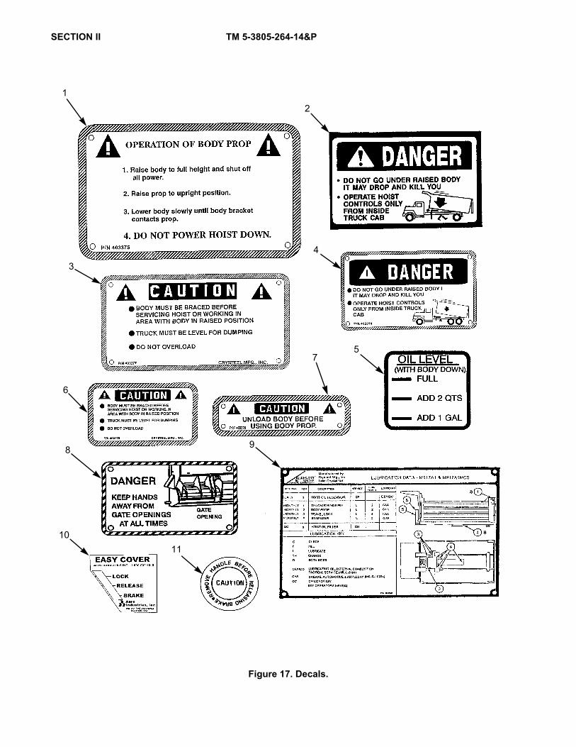
SECTION II TM 5-3805-264-14&P
Figure 17. Decals.
12
3
4
5
6
8
7
9
1011
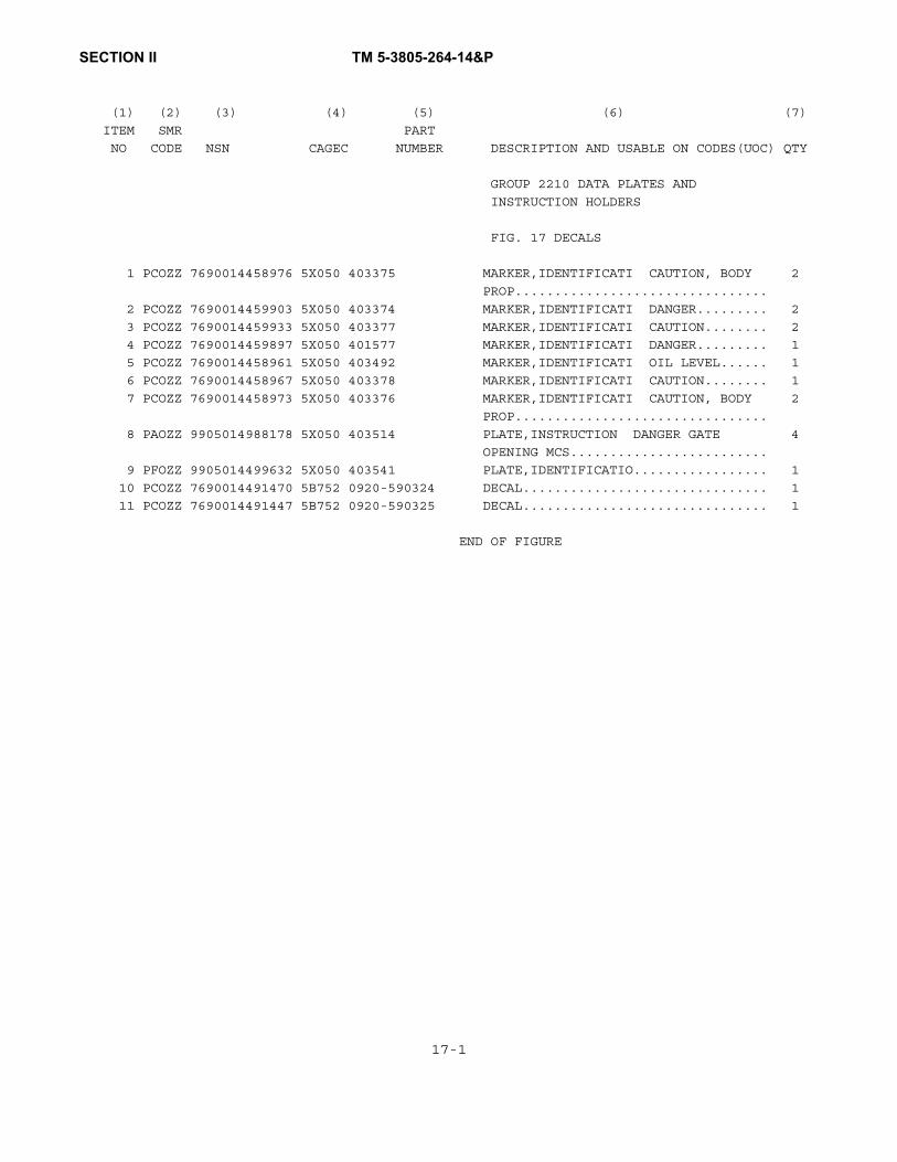
SECTION II TM 5-3805-264-14&P
(1) (2) (3) (4) (5) (6) (7)
ITEM SMR PART
NO CODE NSN CAGEC NUMBER DESCRIPTION AND USABLE ON CODES(UOC) QTY
GROUP 2210 DATA PLATES AND
INSTRUCTION HOLDERS
FIG. 17 DECALS
1 PCOZZ 7690014458976 5X050 403375 MARKER,IDENTIFICATI CAUTION, BODY 2
PROP................................
2 PCOZZ 7690014459903 5X050 403374 MARKER,IDENTIFICATI DANGER......... 2
3 PCOZZ 7690014459933 5X050 403377 MARKER,IDENTIFICATI CAUTION........ 2
4 PCOZZ 7690014459897 5X050 401577 MARKER,IDENTIFICATI DANGER......... 1
5 PCOZZ 7690014458961 5X050 403492 MARKER,IDENTIFICATI OIL LEVEL...... 1
6 PCOZZ 7690014458967 5X050 403378 MARKER,IDENTIFICATI CAUTION........ 1
7 PCOZZ 7690014458973 5X050 403376 MARKER,IDENTIFICATI CAUTION, BODY 2
PROP................................
8 PAOZZ 9905014988178 5X050 403514 PLATE,INSTRUCTION DANGER GATE 4
OPENING MCS.........................
9 PFOZZ 9905014499632 5X050 403541 PLATE,IDENTIFICATIO................. 1
10 PCOZZ 7690014491470 5B752 0920-590324 DECAL............................... 1
11 PCOZZ 7690014491447 5B752 0920-590325 DECAL............................... 1
END OF FIGURE
17-1

SECTION II TM 5-3805-264-14&P
Figure 18. Hydraulic Pump Assembly.
2-20
1
1516
17 18
16
20
10
10
1113
14
23
45
710
12
13
12
1110
987
6
19
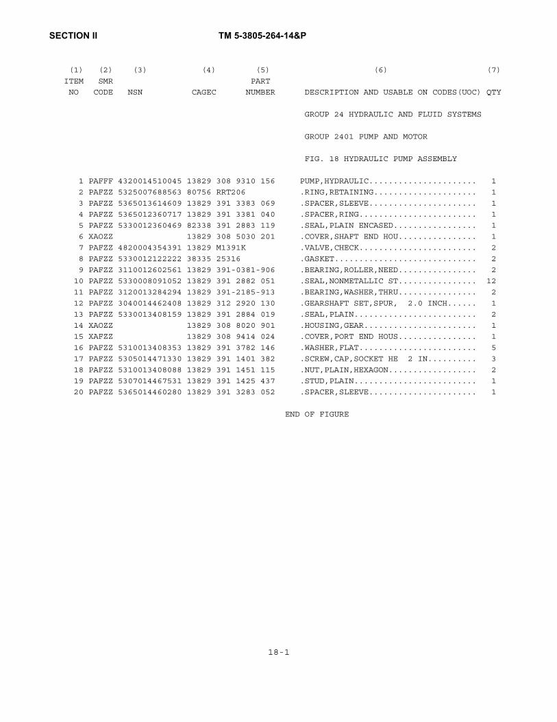
SECTION II TM 5-3805-264-14&P
(1) (2) (3) (4) (5) (6) (7)
ITEM SMR PART
NO CODE NSN CAGEC NUMBER DESCRIPTION AND USABLE ON CODES(UOC) QTY
GROUP 24 HYDRAULIC AND FLUID SYSTEMS
GROUP 2401 PUMP AND MOTOR
FIG. 18 HYDRAULIC PUMP ASSEMBLY
1 PAFFF 4320014510045 13829 308 9310 156 PUMP,HYDRAULIC...................... 1
2 PAFZZ 5325007688563 80756 RRT206 .RING,RETAINING..................... 1
3 PAFZZ 5365013614609 13829 391 3383 069 .SPACER,SLEEVE...................... 1
4 PAFZZ 5365012360717 13829 391 3381 040 .SPACER,RING........................ 1
5 PAFZZ 5330012360469 82338 391 2883 119 .SEAL,PLAIN ENCASED................. 1
6 XAOZZ 13829 308 5030 201 .COVER,SHAFT END HOU................ 1
7 PAFZZ 4820004354391 13829 M1391K .VALVE,CHECK........................ 2
8 PAFZZ 5330012122222 38335 25316 .GASKET............................. 2
9 PAFZZ 3110012602561 13829 391-0381-906 .BEARING,ROLLER,NEED................ 2
10 PAFZZ 5330008091052 13829 391 2882 051 .SEAL,NONMETALLIC ST................ 12
11 PAFZZ 3120013284294 13829 391-2185-913 .BEARING,WASHER,THRU................ 2
12 PAFZZ 3040014462408 13829 312 2920 130 .GEARSHAFT SET,SPUR, 2.0 INCH...... 1
13 PAFZZ 5330013408159 13829 391 2884 019 .SEAL,PLAIN......................... 2
14 XAOZZ 13829 308 8020 901 .HOUSING,GEAR....................... 1
15 XAFZZ 13829 308 9414 024 .COVER,PORT END HOUS................ 1
16 PAFZZ 5310013408353 13829 391 3782 146 .WASHER,FLAT........................ 5
17 PAFZZ 5305014471330 13829 391 1401 382 .SCREW,CAP,SOCKET HE 2 IN.......... 3
18 PAFZZ 5310013408088 13829 391 1451 115 .NUT,PLAIN,HEXAGON.................. 2
19 PAFZZ 5307014467531 13829 391 1425 437 .STUD,PLAIN......................... 1
20 PAFZZ 5365014460280 13829 391 3283 052 .SPACER,SLEEVE...................... 1
END OF FIGURE
18-1
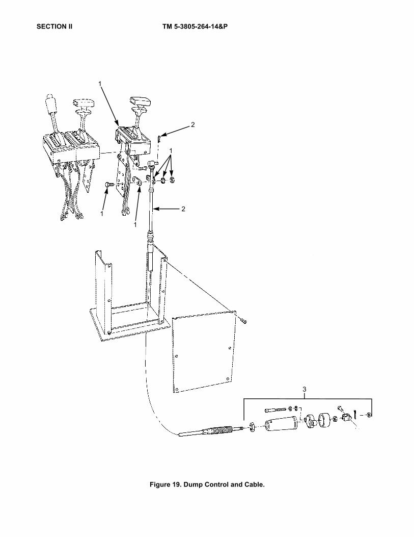
SECTION II TM 5-3805-264-14&P
Figure 19. Dump Control and Cable.
3
11
1
2
1
2

SECTION II TM 5-3805-264-14&P
(1) (2) (3) (4) (5) (6) (7)
ITEM SMR PART
NO CODE NSN CAGEC NUMBER DESCRIPTION AND USABLE ON CODES(UOC) QTY
GROUP 2403 HYDRAULIC CONTROLS AND/OR
MANUAL CONTROLS
FIG. 19 DUMP CONTROL AND CABLE
1 PAOZZ 2590014427238 60602 55940-4 CONTROL ASSEMBLY,PU................. 1
2 PFOZZ 2590014457883 60602 45884-48 CONTROL ASSEMBLY,PU................. 1
UOC:7A1,7E1
2 PFOZZ 2590015287521 64678 FLD/45884 0072 CONTROL ASSEMBLY,PU................. 1
UOC:7A2,7E2
3 PAOZZ 4820014468874 04710 01-5000-35 PARTS KIT,VALVE..................... 1
END OF FIGURE
19-1

SECTION II TM 5-3805-264-14&P
Figure 20. Filter Element, Hydraulic.
1

SECTION II TM 5-3805-264-14&P
(1) (2) (3) (4) (5) (6) (7)
ITEM SMR PART
NO CODE NSN CAGEC NUMBER DESCRIPTION AND USABLE ON CODES(UOC) QTY
GROUP 2406 STRAINERS, FILTERS, LINES
AND FITTINGS, ETC.
FIG. 20 FILTER ELEMENT, HYDRAULIC
1 PAOZZ 4330014463337 5X050 403366 FILTER ELEMENT,FLUI 10 MICRON...... 1
END OF FIGURE
20-1

SECTION II TM 5-3805-264-14&P
Figure 21. Hydraulic Hoses and Fittings.
1
2
3
14 11
12
11
13
10
7
8
5
9
6
5
4
15
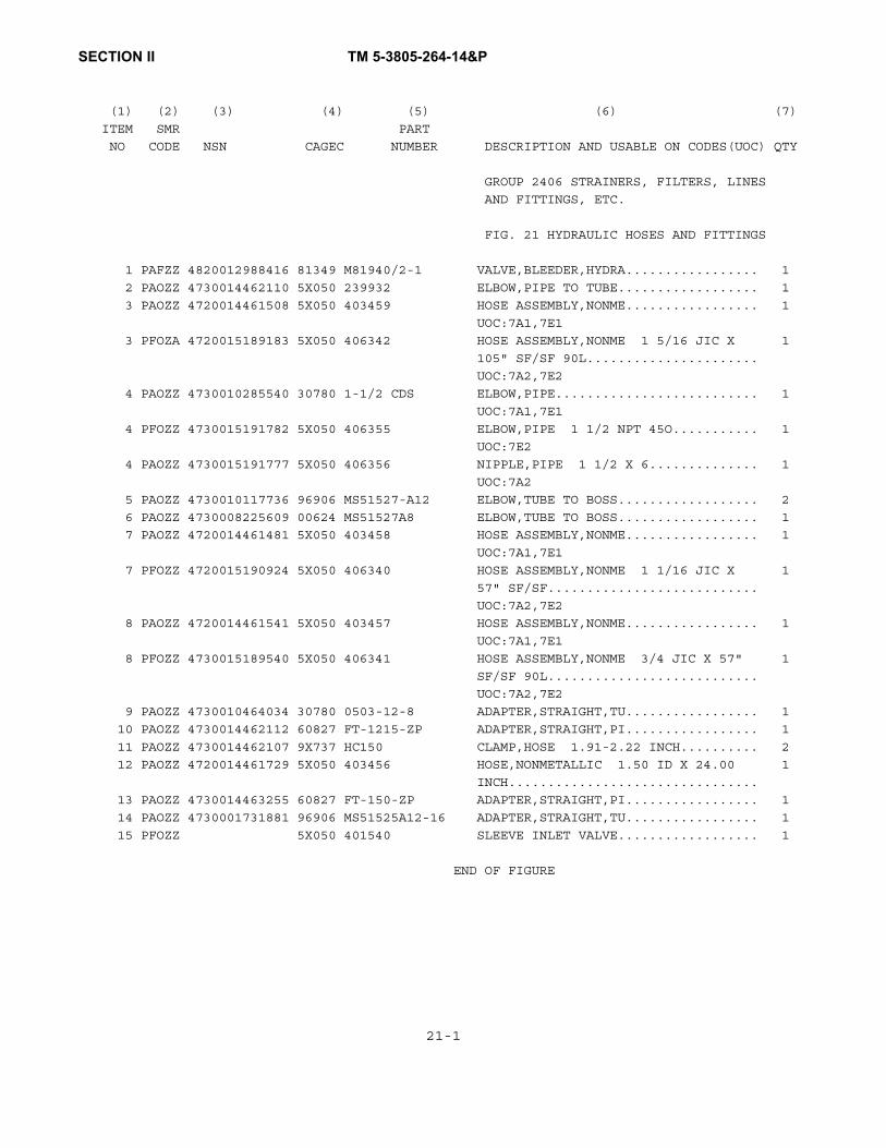
SECTION II TM 5-3805-264-14&P
(1) (2) (3) (4) (5) (6) (7)
ITEM SMR PART
NO CODE NSN CAGEC NUMBER DESCRIPTION AND USABLE ON CODES(UOC) QTY
GROUP 2406 STRAINERS, FILTERS, LINES
AND FITTINGS, ETC.
FIG. 21 HYDRAULIC HOSES AND FITTINGS
1 PAFZZ 4820012988416 81349 M81940/2-1 VALVE,BLEEDER,HYDRA................. 1
2 PAOZZ 4730014462110 5X050 239932 ELBOW,PIPE TO TUBE.................. 1
3 PAOZZ 4720014461508 5X050 403459 HOSE ASSEMBLY,NONME................. 1
UOC:7A1,7E1
3 PFOZA 4720015189183 5X050 406342 HOSE ASSEMBLY,NONME 1 5/16 JIC X 1
105" SF/SF 90L......................
UOC:7A2,7E2
4 PAOZZ 4730010285540 30780 1-1/2 CDS ELBOW,PIPE.......................... 1
UOC:7A1,7E1
4 PFOZZ 4730015191782 5X050 406355 ELBOW,PIPE 1 1/2 NPT 45O........... 1
UOC:7E2
4 PAOZZ 4730015191777 5X050 406356 NIPPLE,PIPE 1 1/2 X 6.............. 1
UOC:7A2
5 PAOZZ 4730010117736 96906 MS51527-A12 ELBOW,TUBE TO BOSS.................. 2
6 PAOZZ 4730008225609 00624 MS51527A8 ELBOW,TUBE TO BOSS.................. 1
7 PAOZZ 4720014461481 5X050 403458 HOSE ASSEMBLY,NONME................. 1
UOC:7A1,7E1
7 PFOZZ 4720015190924 5X050 406340 HOSE ASSEMBLY,NONME 1 1/16 JIC X 1
57" SF/SF...........................
UOC:7A2,7E2
8 PAOZZ 4720014461541 5X050 403457 HOSE ASSEMBLY,NONME................. 1
UOC:7A1,7E1
8 PFOZZ 4730015189540 5X050 406341 HOSE ASSEMBLY,NONME 3/4 JIC X 57" 1
SF/SF 90L...........................
UOC:7A2,7E2
9 PAOZZ 4730010464034 30780 0503-12-8 ADAPTER,STRAIGHT,TU................. 1
10 PAOZZ 4730014462112 60827 FT-1215-ZP ADAPTER,STRAIGHT,PI................. 1
11 PAOZZ 4730014462107 9X737 HC150 CLAMP,HOSE 1.91-2.22 INCH.......... 2
12 PAOZZ 4720014461729 5X050 403456 HOSE,NONMETALLIC 1.50 ID X 24.00 1
INCH................................
13 PAOZZ 4730014463255 60827 FT-150-ZP ADAPTER,STRAIGHT,PI................. 1
14 PAOZZ 4730001731881 96906 MS51525A12-16 ADAPTER,STRAIGHT,TU................. 1
15 PFOZZ 5X050 401540 SLEEVE INLET VALVE.................. 1
END OF FIGURE
21-1

SECTION II TM 5-3805-264-14&P
Figure 22. Cylinder Assembly, Hoist.
2-14
1
2
1312
11
10
98
7
12
14
6
5
4
2
32

SECTION II TM 5-3805-264-14&P
(1) (2) (3) (4) (5) (6) (7)
ITEM SMR PART
NO CODE NSN CAGEC NUMBER DESCRIPTION AND USABLE ON CODES(UOC) QTY
GROUP 2407 HYDRAULIC CYLINDERS
FIG. 22 CYLINDER ASSEMBLY, HOIST
1 PFFFF 3040014463620 5X050 403236 CYLINDER ASSEMBLY,A................. 1
2 PAFZA 5330014471113 02249 034-55008-53118 .PARTS KIT,SEAL REPL INCLUDES ALL 1
WEAR RINGS, GUIDE RINGS, RET. RINGS,
WIPERS, RET. WIPERS, U-CUP SEALS...
3 PAFZZ 3040014464665 02249 B12071-0500 .RING,PISTON 5 INCH................ 2
4 PAFZZ 3040014466277 02249 B12071-0400 .RING,PISTON 4 INCH................ 1
4 PAFZZ 3040014466274 02249 B12071-0300 .RING,PISTON 3 INCH................ 1
5 PAFZZ 3040014466280 02249 0263914 .RING,PISTON 3.5 INCH.............. 1
5 XDFZZ 02249 0263984 .RING,PISTON 4.5 INCH.............. 2
6 XDFZZ 02249 002-55074-04844 .BARREL ASSEMBLY.................... 1
7 XDFZZ 02249 062-50049-04752 .SLEEVE ASSY 5 INCH................ 1
8 XDFZZ 02249 062-40044-04689 .SLEEVE ASSY 4 INCH................ 1
9 PAFZZ 5365013403898 01276 900598-12S .PLUG,MACHINE THREAD 1 1/16-12, 1
WITH O-RING.........................
10 XDFZZ 02249 063-30135-04992 .PLUNGER ASSY 3 INCH............... 1
11 PAFZZ 5365012174133 01276 900598-8S .PLUG,MACHINE THREAD 3/4-16, WITH 1
O-RING..............................
12 PAFZZ 5365014464322 02249 035-17002-00225 .SPACER,SLEEVE...................... 3
13 PAFZZ 5325014464051 02249 083-10005-00562 .RING,RETAINING 5 INCH............. 1
13 PAFZZ 5325014464052 02249 083-50003-00462 .RING,RETAINING 4 INCH............. 1
13 PAFZZ 5325014464053 02249 083-50003-00362 .RING,RETAINING 3 INCH............. 1
14 PAFZZ 5325014469182 02249 B9971-00550 .RING,RETAINING 5 INCH............. 1
14 PAFZZ 5325014469204 02249 083-50002-00450 .RING,RETAINING 4 INCH............. 1
14 PAFZZ 5325014469210 02249 083-50002-00350 .RING,RETAINING 3 INCH............. 1
END OF FIGURE
22-1

SECTION II TM 5-3805-264-14&P
Figure 23. Hydraulic Reservoir Assembly.
15
16
15
17
24
262728
29
14
13
12
7
6
2
5
811
10
92
3
1
2-17
2
3-7
4
1
1819
20
22
2123
25

SECTION II TM 5-3805-264-14&P
(1) (2) (3) (4) (5) (6) (7)
ITEM SMR PART
NO CODE NSN CAGEC NUMBER DESCRIPTION AND USABLE ON CODES(UOC) QTY
GROUP 2408 LIQUID TANKS OR
RESERVOIRS
FIG. 23 HYDRAULIC RESERVOIR ASSEMBLY
1 PGOOZ 2590014470748 5X050 126615 TANK,OIL,HYDRAULIC.................. 1
2 PFOZZ 2940014463570 5X050 403365 .FILTER BODY,FLUID.................. 1
3 PAOZZ 5306012719425 60827 PS-0001 ..BOLT,MACHINE 5/16-18X1.00 INCH... 4
4 PAOZZ 5331014474034 60827 251-70-BN ..O-RING............................ 1
5 XAOZZ 60827 TR-1200-01 ..HOUSING,PORT...................... 1
6 PAOZZ 5331014474040 60827 246-70-BN ..O-RING............................ 1
7 PAOZZ 5331014473098 60827 TS-355-70-BN ..O-RING............................ 1
8 PAOZZ 5305000680510 80204 B1821BH038C100N .SCREW,CAP,HEXAGON H 3/8-16X1.00... 4
9 PAOZZ 4730002041272 30780 2102-2-2 .ELBOW,PIPE......................... 1
10 PAOZZ 6685014471188 5X050 403367 .GAGE,PRESSURE,DIAL................. 1
11 PAOZZ 4730009213624 81346 A733S-6CFG .NIPPLE,PIPE 1/8NPT X 1.50......... 1
12 XDOZZ 5X050 403368 .PIPE,SPECIAL 1.50 X 18.75 INCH.... 1
13 PAOZZ 2590014461903 5X050 403246 .CAP,FILLER OPENING................. 1
14 PAOZZ 5305009931848 70318 A1BMW6024G .SCREW,MACHINE 10-32X0.75.......... 6
15 PAOZZ 4730000686616 79470 69X6 .ELBOW,PIPE TO TUBE................. 2
16 MOOZZ 5X050 239635X1.50 .TUBE,SIGHT 3/8 OD X 1.50 FT, MAKE 1
FROM BULK PN: PT24006NA (79470).....
17 PFOZZ 4730002783888 30780 0102-12-8 REDUCER,PIPE 3/4"M X 1/2"F......... 1
18 PFOZZ 4730002892357 30780 2102-8-8 ELBOW,PIPE 1/2".................... 1
19 XDOZZ 5X050 401288 HOSE ASSY 1/2 X 20 IN.............. 1
20 XDOZZ 64678 23-09130-003 SPACER,PLATE........................ 1
21 PAOZZ 5310000614650 45152 114356A NUT,SELF-LOCKING,HE 1/4-20......... 1
22 XDOZZ 5X050 403678 CLAMP,HOSE,SST...................... 1
23 XDOZZ 5X050 403677 CAP,PIPE 1/2" NPT.................. 1
24 PAOZZ 5305000680509 80204 B1821BH025C125N SCREW,CAP,HEXAGON H................. 1
25 PAFZZ 5310004883889 96906 MS51943-39 NUT,SELF-LOCKING,HE................. 4
26 XDOZZ 5X050 237379 SPACER.............................. 4
27 PAOZZ 5310005847888 96906 MS35338-51 WASHER,LOCK 3/4.................... 4
28 PAOZZ 5310008098533 96906 MS27183-23 WASHER,FLAT 3/4.................... 4
UOC:7A1,7E1
28 PAOZZ 5310012671684 96906 MS51412-10 WASHER,FLAT 1/2"................... 8
29 PAOZZ 5305000712071 80204 B1821BH050C200N SCREW,CAP,HEXAGON H 1/2-13X2.00.... 4
END OF FIGURE
23-1
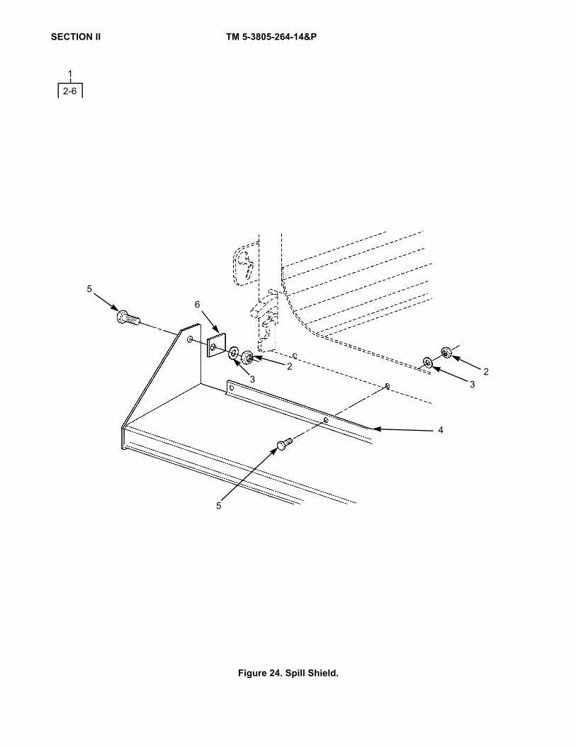
SECTION II TM 5-3805-264-14&P
Figure 24. Spill Shield.
5
4
3
56
3
1
2-6
22

SECTION II TM 5-3805-264-14&P
(1) (2) (3) (4) (5) (6) (7)
ITEM SMR PART
NO CODE NSN CAGEC NUMBER DESCRIPTION AND USABLE ON CODES(UOC) QTY
GROUP 33 SPECIAL PURPOSE KITS
GROUP 3307 SPECIAL PURPOSE KITS
FIG. 24 SPILL SHIELD
1 PAOZZ 2510015184549 5X050 142607 SPILL SHIELD........................ 1
2 PAOZZ 5X050 402038 .HEX,LOCKNUT 3/8 NC................ 8
3 PAOZZ 5310000806004 96906 MS27183-14 .WASHER,FLAT........................ 8
4 XAOZZ 5X050 150380 .SPILL SHIELD 12"................... 1
5 PAOZZ 5X050 400121 .CAPSCREW,HEXHEAD 3/8NC X 1........ 8
6 XDOZZ 5X050 201834 .TAB, SPILL SHIELD M................ 2
END OF FIGURE
24-1/24-2 Blank


SECTION II TM 5-3805-264-14&P
(1) (2) (3) (4) (5) (6) (7) ITEM SMR PART
NO CODE NSN CAGEC NUMBER DESCRIPTION AND USABLE ON CODES(UOC) QTY
GROUP 94 REPAIR KITS
GROUP 9401 REPAIR KITS
FIG. KITS
PAOZZ 3040014981887 5X050 404939 PARTS KIT,LINEAR AC................. 1
UOC:7A1,7E1
ARM,WINDSHIELD WIPE( 1) 13-23
BEARING,PISTON ROD ( 1) 13-22
PACKING,PREFORMED ( 2) 13-9
PACKING,PREFORMED ( 1) 13-16
PREFORMED,PACKING ( 1) 13-20
SEAL,PLAIN ( 2) 13-21
SEAL,PLAIN ( 2) 13-13
STRIP,METAL ( 1) 13-14
PAOZZ 3040014981885 5X050 404940 PARTS KIT,LINEAR AC................. 1
UOC:7A1,7E1
VALVE,PILOT ASSY ( 1) 13-35
VALVE,REGULATING,FL( 1) 13-31
END OF FIGURE
KITS-1

SECTION II TM 5-3805-264-14&P
(1) (2) (3) (4) (5) (6) (7) ITEM SMR PART
NO CODE NSN CAGEC NUMBER DESCRIPTION AND USABLE ON CODES(UOC) QTY
GROUP 95 GENERAL USE STANDARDIZED
PARTS
GROUP 9501 HARDWARE SUPPLIES AND
BULK MATERIEL, COMMON
FIG. BULK
1 XDOZZ 77060 68240R CONDUIT............................. V
2 PAOZZ 5510002559269 81349 MILL2037 LUMBER,HARDWOOD..................... V
3 PAOZZ 4720009254955 79470 PT24006NA TUBING,NONMETALLIC 3/8 OD.......... V
4 PAOZZ 4720013958773 79470 NT10006 TUBING,NONMETALLIC.................. V
5 PAOZZ 4720011829067 61424 PFT-6B-BLK-100 TUBING,NONMETALLIC.................. V
END OF FIGURE
BULK-1

SECTION IV TM 5-3805-264-14&P
CROSS-REFERENCE INDEXES
NATIONAL STOCK NUMBER INDEX
STOCK NUMBER FIG. ITEM STOCK NUMBER FIG. ITEM
5310-00-003-9174 11 3 5310-00-584-7888 23 27
4730-00-044-4035 14 5 5310-00-637-9541 15 11
4730-00-050-4208 10 14 5315-00-721-8370 10 9
5999-00-057-2929 4 7 5305-00-724-7222 9 4
4730-00-057-5555 14 11 10 13
5310-00-061-4650 7 11 11 2
7 19 5305-00-724-7228 12 13
15 45 5305-00-725-2317 11 13
23 21 5310-00-732-0558 15 12
5310-00-061-4651 9 2 5340-00-753-3741 16 5
10 11 5325-00-768-8563 18 2
11 4 5325-00-803-7301 15 43
5305-00-068-0508 7 9 5330-00-809-1052 18 10
7 21 5310-00-809-4058 15 48
5305-00-068-0509 23 24 5310-00-809-4061 16 3
5305-00-068-0510 14 9 5310-00-809-8533 23 28
23 8 5315-00-809-8786 11 18
4730-00-068-6616 23 15 5310-00-814-0672 16 4
5305-00-071-2071 12 4 5310-00-820-6653 12 12
23 29 4730-00-822-5609 21 6
5305-00-071-2076 9 9 5310-00-823-8804 7 10
12 9 7 20
5305-00-071-2513 15 16 5935-00-833-8561 4 10
5310-00-080-6004 14 13 5970-00-833-8562 4 9
24 3 5310-00-833-8567 4 6
5310-00-088-1251 15 35 5935-00-856-3513 1 3
4730-00-137-7875 13 29 7 2
5935-00-153-4397 7 5 4730-00-921-3624 23 11
7 13 4720-00-925-4955 BULK 3
4730-00-173-1881 21 14 5310-00-935-9021 11 17
5325-00-174-9341 8 12 14 14
4730-00-204-1272 23 9 5305-00-947-4358 10 3
5306-00-226-4827 12 7 5306-00-957-7531 15 21
5510-00-255-9269 BULK 1 5305-00-984-7353 15 32
5305-00-269-2803 16 2 5305-00-988-1725 15 7
4730-00-277-8289 14 36 15 29
4730-00-278-3888 14 8 5305-00-989-7434 5 1
23 17 5305-00-993-1848 23 14
4730-00-289-2357 14 7 4730-01-011-7736 21 5
23 18 4730-01-028-5540 21 4
5310-00-347-0021 2 5 5340-01-032-8448 16 6
5940-00-399-6676 4 8 4730-01-046-4034 21 9
5310-00-409-3333 10 4 4730-01-048-5260 14 3
4820-00-435-4391 18 7 14 18
5310-00-488-3889 9 10 14 22
12 3 14 28
23 25 4730-01-048-7873 14 4
5325-00-530-7968 15 30 14 19
5305-00-543-4372 15 10 14 23
5310-00-550-1130 15 28 14 29I-1

SECTION IV TM 5-3805-264-14&P
4730-01-056-4990 14 2 4820-01-418-4232 14 12
14 17 5999-01-422-9740 7 7
14 21 8 3
14 27 2590-01-442-7238 19 1
4730-01-062-2570 14 16 5340-01-445-7778 15 46
5305-01-075-0957 15 41 5340-01-445-7781 3 7
6220-01-086-5691 3 1 2590-01-445-7883 19 2
6220-01-095-0011 3 4 7690-01-445-8961 17 5
4730-01-096-9128 14 1 7690-01-445-8967 17 6
4730-01-134-3571 14 26 7690-01-445-8973 17 7
5305-01-162-2358 11 7 7690-01-445-8976 17 1
5325-01-163-6558 3 2 6150-01-445-9130 4 1
2540-01-175-7257 16 1 5342-01-445-9481 15 6
5330-01-212-2222 18 8 5340-01-445-9486 9 3
5935-01-214-4163 13 39 7690-01-445-9897 17 4
5935-01-214-5259 7 8 7690-01-445-9903 17 2
5365-01-217-4133 22 11 7690-01-445-9933 17 3
5975-01-226-8078 4 4 6220-01-445-9978 3 5
8 2 6220-01-445-9981 3 6
5975-01-230-4370 4 5 5365-01-446-0280 18 20
5330-01-236-0469 18 5 5342-01-446-0902 15 22
5365-01-236-0717 18 4 5340-01-446-0947 11 14
4730-01-244-3552 14 20 5930-01-446-0980 5 3
3110-01-260-2561 18 9 4720-01-446-1481 21 7
5310-01-267-1684 23 28 4720-01-446-1508 21 3
5306-01-271-9425 23 3 4720-01-446-1541 21 8
5325-01-283-3513 3 3 4720-01-446-1729 21 12
4820-01-298-8416 21 1 2510-01-446-1842 10 8
5935-01-308-7866 4 2 2590-01-446-1903 23 13
5935-01-308-8599 8 4 4730-01-446-2107 21 11
5975-01-310-5011 6 3 4730-01-446-2108 13 8
7 6 4730-01-446-2110 21 2
13 37 4730-01-446-2112 21 10
3120-01-328-4294 18 11 3040-01-446-2408 18 12
5930-01-332-0680 2 2 3040-01-446-2413 11 19
5310-01-333-6436 15 18 5315-01-446-3121 9 8
5930-01-336-0919 5 2 5360-01-446-3122 15 14
5935-01-339-9574 6 4 5360-01-446-3190 15 47
5940-01-340-0587 8 7 5360-01-446-3194 15 23
5365-01-340-3898 22 9 4730-01-446-3255 21 13
5310-01-340-8088 18 18 4330-01-446-3337 20 1
5330-01-340-8159 18 13 2530-01-446-3340 15 34
5310-01-340-8353 18 16 2940-01-446-3570 23 2
4730-01-345-6065 13 28 3040-01-446-3620 22 1
5975-01-355-6985 7 4 3040-01-446-3782 15 40
7 14 3040-01-446-3790 15 15
5365-01-361-4609 18 3 3040-01-446-3793 15 19
5999-01-364-1237 8 10 5325-01-446-4051 22 13
5940-01-366-1563 7 17 5325-01-446-4052 22 13
5999-01-406-4110 13 38 5325-01-446-4053 22 13
I-2
CROSS-REFERENCE INDEXES
NATIONAL STOCK NUMBER INDEX
STOCK NUMBER FIG. ITEM STOCK NUMBER FIG. ITEM

SECTION IV TM 5-3805-264-14&P,C1
5360-01-446-4054 15 36 4710-01-466-4881 BULK 25365-01-446-4322 22 12 5999-01-466-5398 1 73040-01-446-4665 22 3 5305-01-466-7940 2 43040-01-446-4689 15 37 6150-01-466-9174 8 55340-01-446-4927 11 12 6220-01-469-5480 2 65340-01-446-5137 11 11 5340-01-469-6693 11 63040-01-446-6274 22 4 5940-01-469-7988 4 33040-01-446-6277 22 4 3020-01-473-2738 15 333040-01-446-6280 22 5 3040-01-473-2741 15 446150-01-446-6344 8 1 5330-01-473-2903 13 346150-01-446-6345 6 1 2510-01-473-8250 12 13020-01-446-6405 15 31 2510-01-473-8251 12 13020-01-446-6409 15 4 4730-01-473-9667 14 383020-01-446-6412 15 2 4730-01-473-9699 14 375315-01-446-6724 15 3 5330-01-474-2447 13 32
5340-01-474-6446 15 425307-01-446-7531 18 19 5340-01-474-6449 15 275360-01-446-7903 15 20 5340-01-474-6455 15 15325-01-446-8320 8 9 5340-01-474-6462 15 54820-01-446-8874 19 3 5220-01-474-8432 13 155305-01-446-8972 15 25 3130-01-474-9064 15 95315-01-446-9174 13 44 5340-01-474-9576 15 495315-01-446-9177 13 1 5365-01-475-2277 13 335325-01-446-9182 22 14 5342-01-475-2802 15 175325-01-446-9204 22 14 5310-01-481-4919 13 125325-01-446-9210 22 14 5330-01-482-8766 13 165315-01-447-0479 11 8 5340-01-492-7615 15 265315-01-447-0480 10 1 3040-01-497-0345 12 115315-01-447-0481 11 9 5930-01-497-0704 1 102590-01-447-0748 23 1 6150-01-497-4879 7 125330-01-447-1113 22 2 6150-01-497-4886 7 16685-01-447-1188 23 10 6150-01-497-5582 1 25305-01-447-1330 18 17 4710-01-497-5644 12 63040-01-447-2738 13 3 5340-01-497-8124 12 85331-01-447-3098 23 7 3040-01-498-1885 KITS5331-01-447-4034 23 4 3040-01-498-1887 KITS5331-01-447-4040 23 6 9905-01-498-7857 1 95315-01-447-5712 15 24 9905-01-498-7858 1 95315-01-448-8804 15 38 9905-01-498-7859 1 97690-01-449-1447 17 11 9905-01-498-7860 1 97690-01-449-1470 17 10 9905-01-498-8178 17 85340-01-449-5470 9 11 5925-01-499-3416 1 65342-01-449-5475 15 8 5310-01-502-2940 13 272540-01-449-5775 15 13 5325-01-502-5209 13 259905-01-449-9632 17 9 5315-01-507-0537 12 144320-01-451-0045 18 1 5930-01-507-6990 1 43040-01-459-5141 1 1 3040-01-515-7916 13 35940-01-462-1717 6 6 5935-01-518-0417 8 135940-01-462-1718 4 11 5365-01-518-2872 14 402530-01-464-9916 7 16 5935-01-518-3690 3 9
I-3
CROSS-REFERENCE INDEXES
NATIONAL STOCK NUMBER INDEX
STOCK NUMBER FIG. ITEM STOCK NUMBER FIG. ITEM
*

SECTION IV TM 5-3805-264-14&P
5935-01-518-3692 3 82510-01-518-4549 24 16220-01-518-6827 3 16240-01-518-6843 3 45310-01-518-7454 12 154720-01-518-9183 21 34730-01-518-9184 14 394730-01-518-9540 21 84720-01-519-0924 21 74730-01-519-1777 21 44730-01-519-1782 21 45930-01-520-4456 2 2
I-4
CROSS-REFERENCE INDEXES
NATIONAL STOCK NUMBER INDEX
STOCK NUMBER FIG. ITEM STOCK NUMBER FIG. ITEM

SECTION IV TM 5-3805-264-14&P,C1
CROSS-REFERENCE INDEXES
PART NUMBER INDEX
CAGEC PART NUMBER NSN FIG ITEM
81343 AS15003-1 4730-00-050-4208 10 14
64678 A06-24606-276 6150-01-466-9174 8 5
64678 A06-30769-101 5930-01-520-4456 2 2
70318 A1BMW6024G 5305-00-993-1848 23 14
81346 A733S-6CFG 4730-00-921-3624 23 11
64678 BCI/231E 5999-01-466-5398 1 7
7J764 BNT220 1 5
7J764 BNT22002 5930-01-507-6990 1 4
02249 B12071-0300 3040-01-446-6274 22 4
02249 B12071-0400 3040-01-446-6277 22 4
02249 B12071-0500 3040-01-446-4665 22 3
80204 B1821BH025C075N 5305-00-068-0508 7 9
7 21
80204 B1821BH025C125N 5305-00-068-0509 23 24
80204 B1821BH025C250N 5305-00-071-2513 15 16
80204 B1821BH031C100N 5306-00-226-4827 12 7
80204 B1821BH038C075N 5305-00-543-4372 15 10
80204 B1821BH038C100N 5305-00-068-0510 14 9
23 8
80204 B1821BH038C150N 5305-00-725-2317 11 13
80204 B1821BH050C200N 5305-00-071-2071 12 4
23 29
80204 B1821BH050C325N 5305-00-071-2076 9 9
12 9
80204 B1821BH063C200N 5305-00-724-7222 9 4
10 13
11 2
80204 B1821BH063C300N 5305-00-724-7228 12 13
80204 B1821BH075C400N 5305-00-947-4358 10 3
12662 B490A 6220-01-445-9978 3 5
12662 B490R 6220-01-445-9981 3 6
02249 B9971-00550 5325-01-446-9182 22 14
5X050 CMG 400892 5310-01-518-7454 12 15
7J764 CM10P 1 8
52793 CW7435-57C 5310-00-820-6653 12 12
7J764 C21PA03 5930-01-497-0704 1 10
79470 C3109X8X6 4730-00-044-4035 14 5
5B752 ECT 13 CRY 2540-01-449-5775 15 13
81348 FFW92 5310-00-003-9174 11 3
64678 FLD/45884 0072 19 2
60827 FT-1215-ZP 4730-01-446-2112 21 10
60827 FT-150-ZP 4730-01-446-3255 21 13
9X737 HC150 4730-01-446-2107 21 11I-5
*

SECTION IV TM 5-3805-264-14&P
81349 MILL2037 5510-00-255-9269 BULK 1
80205 MS16562-51 5315-00-809-8786 11 18
96906 MS16624-1050 5325-00-803-7301 15 43
96906 MS16624-1100 5325-00-530-7968 15 30
96906 MS27183-10 5310-00-809-4058 15 48
96906 MS27183-14 5310-00-080-6004 14 13
24 3
96906 MS27183-15 5310-00-809-4061 16 3
96906 MS27183-23 5310-00-809-8533 23 28
96906 MS27183-9 5310-00-823-8804 7 10
7 20
96906 MS35191-306 5305-00-984-7353 15 32
96906 MS35206-281 5305-00-988-1725 15 7
15 29
96906 MS35207-263 5305-00-989-7434 5 1
80205 MS35333-40 5310-00-550-1130 15 28
80205 MS35338-46 5310-00-637-9541 15 11
96906 MS35338-51 5310-00-584-7888 23 27
96906 MS51412-10 5310-01-267-1684 23 28
96906 MS51525A12-16 4730-00-173-1881 21 14
96906 MS51527-A12 4730-01-011-7736 21 5
00624 MS51527A8 4730-00-822-5609 21 6
96906 MS51849-100 5305-01-075-0957 15 41
96906 MS51943-35 5310-00-935-9021 11 17
14 14
96906 MS51943-39 5310-00-488-3889 9 10
12 3
23 25
96906 MS51943-45 5310-00-409-3333 10 4
96906 MS51967-8 5310-00-732-0558 15 12
80205 MS90726-60 5305-00-269-2803 16 2
13829 M1391K 4820-00-435-4391 18 7
96906 M45912/3-6FG8C 5310-00-814-0672 16 4
81349 M45913/1-4CG5C 5310-00-088-1251 15 35
81349 M81940/2-1 4820-01-298-8416 21 1
80205 NAS561-8-48 5315-00-721-8370 10 9
60827 PS-0001 5306-01-271-9425 23 3
79470 PT24006NA 4720-00-925-4955 BULK 3
80756 RRT206 5325-00-768-8563 18 2
60827 TR-1200-01 23 5
60827 TS-355-70-BN 5331-01-447-3098 23 7
93061 VS209P-8-4 4730-01-345-6065 13 28
93061 VS269NTA-6-4 4730-01-244-3552 14 20
7J764 WE11H415E 9905-01-498-7858 1 9
7J764 WE11H416E 9905-01-498-7857 1 9I-6
CROSS-REFERENCE INDEXES
PART NUMBER INDEX
CAGEC PART NUMBER NSN FIG ITEM

SECTION IV TM 5-3805-264-14&P
7J764 WE11H417E 9905-01-498-7860 1 9
7J764 WE11H418E 9905-01-498-7859 1 9
02249 002-55074-04844 22 6
04710 01-5000-35 4820-01-446-8874 19 3
30780 01HP-6 4730-00-057-5555 14 11
79146 010029X11+/- 13 7
30780 0102-12-8 4730-00-278-3888 14 8
23 17
79146 012037 13 30
79146 016964 4730-01-446-2108 13 8
79146 019067. 5315-01-446-9174 13 44
79146 019070 5315-01-446-9177 13 1
79146 020003-7 4710-01-466-4881 BULK 2
02249 0263914 3040-01-446-6280 22 5
02249 0263984 22 5
79146 030084 13 40
5B752 0311-860730 3040-01-446-4689 15 37
5B752 0311-860732 3040-01-446-3782 15 40
5B752 0311-861589 5342-01-446-0902 15 22
5B752 0311-861590 5342-01-475-2802 15 17
5B752 0311-861591 3040-01-446-3793 15 19
5B752 0311-861596 5340-01-474-6449 15 27
5B752 0311-862406 3020-01-473-2738 15 33
5B752 0311-960237 5360-01-446-3194 15 23
5B752 0311-960238 5360-01-446-3122 15 14
5B752 0311-960739 2530-01-446-3340 15 34
5B752 0311-961267 5342-01-449-5475 15 8
5B752 0311-961273 5342-01-445-9481 15 6
5B752 0311-961280 3040-01-446-3790 15 15
5B752 0311-961356 5340-01-492-7615 15 26
5B752 0311-961401 5340-01-474-6462 15 5
5B752 0311-961402 5340-01-474-6455 15 1
5B752 0311-962125 15 39
5B752 0311-962128 3040-01-473-2741 15 44
5B752 0311-962132 5340-01-474-6446 15 42
79146 032135 4820-01-418-4232 14 12
02249 034-55008-53118 5330-01-447-1113 22 2
02249 035-17002-00225 5365-01-446-4322 22 12
79146 035055 14 10
30780 0503-12-8 4730-01-046-4034 21 9
64678 06-22309-048 6220-01-469-5480 2 6
64678 06-24618-000 2 1
02249 062-40044-04689 22 8
02249 062-50049-04752 22 7
02249 063-30135-04992 22 10
I-7
CROSS-REFERENCE INDEXES
PART NUMBER INDEX
CAGEC PART NUMBER NSN FIG ITEM

SECTION IV TM 5-3805-264-14&P
5B752 0710-602155 3130-01-474-9064 15 9
5B752 0715-619601 5360-01-446-7903 15 20
5B752 0715-619602 5360-01-446-3190 15 47
5B752 0715-619800 5360-01-446-4054 15 36
5B752 0720-603557 3020-01-446-6412 15 2
5B752 0750-619592 3020-01-446-6405 15 31
5B752 0750-619594 3020-01-446-6409 15 4
5B752 0765-618830 5340-01-445-7778 15 46
11862 0815-660451 15 35
5B752 0825-670460 5305-01-446-8972 15 25
02249 083-10005-00562 5325-01-446-4051 22 13
02249 083-50002-00350 5325-01-446-9210 22 14
02249 083-50002-00450 5325-01-446-9204 22 14
02249 083-50003-00362 5325-01-446-4053 22 13
02249 083-50003-00462 5325-01-446-4052 22 13
5B752 0835-691616 5315-01-447-5712 15 24
5B752 0840-618512 5315-01-446-6724 15 3
5B752 0840-618513 5315-01-448-8804 15 38
5B752 0920-590324 7690-01-449-1470 17 10
5B752 0920-590325 7690-01-449-1447 17 11
30780 1-1/2 CDS 4730-01-028-5540 21 4
13548 10004R 6220-01-095-0011 3 4
13548 10250R 6240-01-518-6843 3 4
77326 11-700 5935-00-856-3513 1 3
7 2
77326 11-720 5935-00-153-4397 7 5
7 13
77326 11-761 5975-01-355-6985 7 4
7 14
77326 11-763 7 3
5X050 110543 10 2
45152 114356A 5310-00-061-4650 7 11
7 19
15 45
23 21
5X050 117122 5315-01-447-0481 11 9
77060 1201 0300 5935-01-339-9574 6 4
77060 1201 5797 5935-01-308-8599 8 4
77060 12010293 5975-01-226-8078 4 4
8 2
22785 12010973 5935-01-214-4163 13 39
77060 12015199 8 6
77060 12015323 5975-01-310-5011 6 3
7 6
13 37
I-8
CROSS-REFERENCE INDEXES
PART NUMBER INDEX
CAGEC PART NUMBER NSN FIG ITEM

SECTION IV TM 5-3805-264-14&P
77060 12015344 5935-01-518-0417 8 13
77060 12015792 5935-01-214-5259 7 8
77060 1202 0116 5940-01-340-0587 8 7
77060 1204 7938 7 18
77060 1204 8086 2530-01-464-9916 7 16
77060 12045773 5999-01-364-1237 8 10
77060 12047933 8 11
77060 12048074 5940-01-366-1563 7 17
77060 12048159 5940-01-462-1717 6 6
77060 12052924 5325-01-446-8320 8 9
77060 12066304 7 15
77060 12084673 6 2
77060 12085036 6 5
77060 12124582 5999-01-406-4110 13 38
77060 12129493 5940-01-469-7988 4 3
19207 12302814 2540-01-175-7257 16 1
19207 12387349-43 5310-00-061-4651 9 2
10 11
11 4
19207 12420936 5999-01-422-9740 7 7
8 3
5X050 126426 11 5
5X050 126427 11 5
5X050 126615 2590-01-447-0748 23 1
5X050 126617 9 5
5X050 127170 5315-01-447-0480 10 1
5X050 127373 5340-01-469-6693 11 6
5X050 127838 10 15
5X050 127852 5340-01-446-5137 11 11
5X050 127892 11 10
5X050 128125 10 5
5X050 128126 2510-01-446-1842 10 8
5X050 128129 9 1
5X050 128130 5340-01-445-9486 9 3
5X050 128131 5340-01-449-5470 9 11
5X050 128214 3040-01-459-5141 1 1
5X050 129305 10 6
5X050 129306 10 7
5X050 129528 12 10
5X050 129568 11 1
5X050 129652 12 2
5X050 129653 5340-01-497-8124 12 8
5X050 129732 5340-01-446-0947 11 14
5X050 129871 5930-01-446-0980 5 3
5X050 13141 3040-01-515-7916 13 3
I-9
CROSS-REFERENCE INDEXES
PART NUMBER INDEX
CAGEC PART NUMBER NSN FIG ITEM
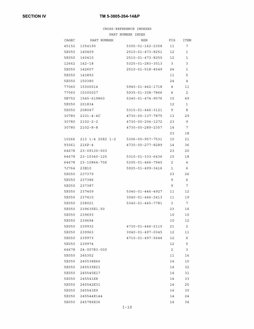
SECTION IV TM 5-3805-264-14&P
45152 1354190 5305-01-162-2358 11 7
5X050 140409 2510-01-473-8251 12 1
5X050 140410 2510-01-473-8250 12 1
12662 142-18 5325-01-283-3513 3 3
5X050 142607 2510-01-518-4549 24 1
5X050 143893 11 5
5X050 150380 24 4
77060 15300014 5940-01-462-1718 4 11
77060 15300027 5935-01-308-7866 4 2
5B752 1545-619860 5340-01-474-9576 15 49
5X050 201834 12 1
5X050 208047 5315-01-446-3121 9 8
30780 2101-4-4C 4730-00-137-7875 13 29
30780 2102-2-2 4730-00-204-1272 23 9
30780 2102-8-8 4730-00-289-2357 14 7
23 18
10266 213 1-4 20X2 1-2 5306-00-957-7531 15 21
93061 216P-4 4730-00-277-8289 14 36
64678 23-09130-003 23 20
64678 23-10340-125 5310-01-333-6436 15 18
64678 23-10864-706 5305-01-466-7940 2 4
7J764 23E10 5925-01-499-3416 1 6
5X050 237379 23 26
5X050 237386 9 6
5X050 237387 9 7
5X050 237409 5340-01-446-4927 11 12
5X050 237410 3040-01-446-2413 11 19
5X050 238021 5340-01-445-7781 3 7
5X050 239635X1.50 23 16
5X050 239693 10 10
5X050 239694 10 12
5X050 239932 4730-01-446-2110 21 2
5X050 239963 3040-01-497-0345 12 11
5X050 239973 4710-01-497-5644 12 6
5X050 239974 12 5
64678 24-00783-000 2 3
5X050 245352 11 16
5X050 245538X66 14 15
5X050 245539X21 14 32
5X050 245540X17 14 31
5X050 245541X8 14 33
5X050 245542X31 14 25
5X050 245543X9 14 30
5X050 245544X144 14 24
5X050 245786X36 14 34
I-10
CROSS-REFERENCE INDEXES
PART NUMBER INDEX
CAGEC PART NUMBER NSN FIG ITEM

SECTION IV TM 5-3805-264-14&P
5X050 245787X38 14 35
60827 246-70-BN 5331-01-447-4040 23 6
60827 251-70-BN 5331-01-447-4034 23 4
38335 25316 5330-01-212-2222 18 8
30780 264NTA-6 4730-01-134-3571 14 26
70485 2872 5325-00-174-9341 8 12
13829 308 5030 201 18 6
13829 308 8020 901 18 14
13829 308 9310 156 4320-01-451-0045 18 1
13829 308 9414 024 18 15
13829 312 2920 130 3040-01-446-2408 18 12
79146 320001 14 6
99321 3507 5310-00-347-0021 2 5
50620 38-22LP 5315-01-507-0537 12 14
13829 391 1401 382 5305-01-447-1330 18 17
13829 391 1425 437 5307-01-446-7531 18 19
13829 391 1451 115 5310-01-340-8088 18 18
13829 391 2882 051 5330-00-809-1052 18 10
82338 391 2883 119 5330-01-236-0469 18 5
13829 391 2884 019 5330-01-340-8159 18 13
13829 391 3283 052 5365-01-446-0280 18 20
13829 391 3381 040 5365-01-236-0717 18 4
13829 391 3383 069 5365-01-361-4609 18 3
13829 391 3782 146 5310-01-340-8353 18 16
13829 391-0381-906 3110-01-260-2561 18 9
13829 391-2185-913 3120-01-328-4294 18 11
5X050 400121 24 5
5X050 401288 23 19
5X050 401332 4730-01-518-9184 14 39
5X050 401540 21 15
5X050 401577 7690-01-445-9897 17 4
5X050 402038 24 2
5X050 403236 3040-01-446-3620 22 1
5X050 403246 2590-01-446-1903 23 13
5X050 403248 6150-01-497-4879 7 12
5X050 403254 6150-01-446-6345 6 1
5X050 403255 6150-01-445-9130 4 1
5X050 403256 6150-01-446-6344 8 1
5X050 403345X148.75 11 20
5X050 403365 2940-01-446-3570 23 2
5X050 403366 4330-01-446-3337 20 1
5X050 403367 6685-01-447-1188 23 10
5X050 403368 23 12
5X050 403374 7690-01-445-9903 17 2
5X050 403375 7690-01-445-8976 17 1
I-11
CROSS-REFERENCE INDEXES
PART NUMBER INDEX
CAGEC PART NUMBER NSN FIG ITEM
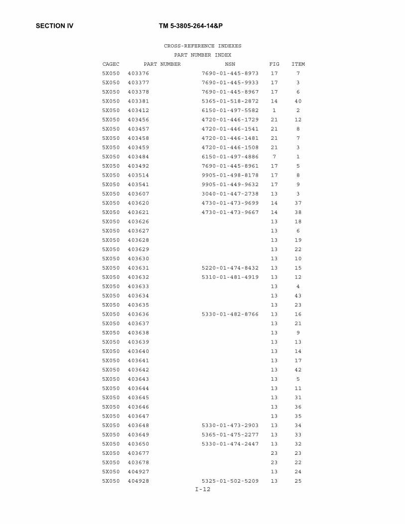
SECTION IV TM 5-3805-264-14&P
5X050 403376 7690-01-445-8973 17 7
5X050 403377 7690-01-445-9933 17 3
5X050 403378 7690-01-445-8967 17 6
5X050 403381 5365-01-518-2872 14 40
5X050 403412 6150-01-497-5582 1 2
5X050 403456 4720-01-446-1729 21 12
5X050 403457 4720-01-446-1541 21 8
5X050 403458 4720-01-446-1481 21 7
5X050 403459 4720-01-446-1508 21 3
5X050 403484 6150-01-497-4886 7 1
5X050 403492 7690-01-445-8961 17 5
5X050 403514 9905-01-498-8178 17 8
5X050 403541 9905-01-449-9632 17 9
5X050 403607 3040-01-447-2738 13 3
5X050 403620 4730-01-473-9699 14 37
5X050 403621 4730-01-473-9667 14 38
5X050 403626 13 18
5X050 403627 13 6
5X050 403628 13 19
5X050 403629 13 22
5X050 403630 13 10
5X050 403631 5220-01-474-8432 13 15
5X050 403632 5310-01-481-4919 13 12
5X050 403633 13 4
5X050 403634 13 43
5X050 403635 13 23
5X050 403636 5330-01-482-8766 13 16
5X050 403637 13 21
5X050 403638 13 9
5X050 403639 13 13
5X050 403640 13 14
5X050 403641 13 17
5X050 403642 13 42
5X050 403643 13 5
5X050 403644 13 11
5X050 403645 13 31
5X050 403646 13 36
5X050 403647 13 35
5X050 403648 5330-01-473-2903 13 34
5X050 403649 5365-01-475-2277 13 33
5X050 403650 5330-01-474-2447 13 32
5X050 403677 23 23
5X050 403678 23 22
5X050 404927 13 24
5X050 404928 5325-01-502-5209 13 25
I-12
CROSS-REFERENCE INDEXES
PART NUMBER INDEX
CAGEC PART NUMBER NSN FIG ITEM

SECTION IV TM 5-3805-264-14&P,C1
5X050 404929 13 20
5X050 404930 13 26
5X050 404931 5310-01-502-2940 13 27
5X050 404932 13 1
5X050 404933 13 2
5X050 404934 13 1
93061 404938 13 41
5X050 404939 3040-01-498-1887 KITS
5X050 404940 3040-01-498-1885 KITS
5X050 406340 4720-01-519-0924 21 7
5X050 406341 4730-01-518-9540 21 8
5X050 406342 4720-01-518-9183 21 3
5X050 406355 4730-01-519-1782 21 4
5X050 406356 4730-01-519-1777 21 4
64670 407023 11 15
60602 45884-48 2590-01-445-7883 19 2
60602 55940-4 2590-01-442-7238 19 1
19204 572929 5999-00-057-2929 4 7
93061 60NTA-6 4730-01-048-5260 14 18
14 22
14 28
93061 60NTA6 4730-01-048-5260 14 3
13548 60085R 6220-01-518-6827 3 1
13548 60202R 6220-01-086-5691 3 1
13548 60700 5325-01-163-6558 3 2
93061 61NTA-6 4730-01-048-7873 14 4
14 19
14 23
14 29
0PXJ7 63-04 5315-01-447-0479 11 8
93061 63NTA-6 4730-01-056-4990 14 2
14 17
14 21
14 27
93061 68NTA-6-4 4730-01-062-2570 14 16
93061 68NTA-6-6 4730-01-096-9128 14 1
93061 68PMT-6-4 13 30
64678 681 545 07 22 5930-01-332-0680 2 2
77060 68240R-276 8 8
79470 69X6 4730-00-068-6616 23 15
19200 7550233-1 5340-00-753-3741 16 5
19200 7550233-2 5340-01-032-8448 16 6
19207 8338561 5935-00-833-8561 4 10
19207 8338562 5970-00-833-8562 4 9
19207 8338564 5940-00-399-6676 4 8
5A910 8338566 5975-01-230-4370 4 5I-13
CROSS-REFERENCE INDEXES
PART NUMBER INDEX
CAGEC PART NUMBER NSN FIG ITEM
*

SECTION IV TM 5-3805-264-14&P
19207 8338567 5310-00-833-8567 4 6
13445 8486 5930-01-336-0919 5 2
01276 900598-12S 5365-01-340-3898 22 9
01276 900598-8S 5365-01-217-4133 22 11
13548 93745 5935-01-518-3692 3 8
13548 94706 5935-01-518-3690 3 9
I-14
CROSS-REFERENCE INDEXES
PART NUMBER INDEX
CAGEC PART NUMBER NSN FIG ITEM

TM 5-3805-264-14&P
D-1
APPENDIX DCOMPONENTS OF END ITEM (COEI) AND BASIC ISSUE ITEMS (BII) LISTS
Section I. INTRODUCTION
D-1. SCOPE.
a. This appendix lists Components of End Item (COEI) and Basic Issue Items (BII) for the M917A1,M917A1 w/MCS, M917A2, and M917A2 w/MCS Dump Truck Body to help you inventory items required for safeand efficient operation.
b. Refer to TM 9-2320-363-10 or TM 9-2320-302-10 for COEI and BII related to the dump truck chas-sis.
D-2. GENERAL.
The COEI and BII Lists are divided into the following sections:a. Section II, Components of End Item. This listing is for informational purposes only and is not
authority to requisition replacements. These items are part of the end item, but are removed and separately pack-aged for transportation or shipment. As part of the end item, these items must be with the end item whenever it isissued or transferred between property accounts. Illustrations are furnished to assist you in identifying the items.
b. Section III, Basic Issue Items. These are the minimum essential items required to place the truckin operation, to operate it, and to perform emergency repairs. Although shipped separately packaged, BII must bewith the truck during operation and whenever it is transferred between property accounts. The illustrations willassist you with hard-to-identify items. This manual is your authority to request/requisition replacement BII, basedon TOE/MTOE authorization of end item.
D-3. EXPLANATION OF COLUMNS.
Below is an explanation of columns found in the tabular listings:a. Column (1) - Illustration Number (Illus Number). This column indicates the number of the illus-
tration that shows the item.b. Column (2) - National Stock Number. Indicates the National Stock Number (NSN) assigned to
the item and will be used for requisitioning purposes.c. Column (3) - Description and Usable On Code. Indicates the Federal item name and, if
required, a minimum description in parentheses to identify and locate the item. The entry for each item ends withthe Commercial and Government Entity Code (CAGEC) in parentheses followed by the part number. Usable OnCode indicates the vehicle to which the item is assigned. Usable on codes for the M917A1, M917A1 w/MCS,M917A2, and M917A2 w/MCS are:
Usable On Code Model7A1 M917A17E1 M917A1 w/MCS7A2 M917A27E2 M917A2 w/MCS

TM 5-3805-264-14&P
D-2
D-3. EXPLANATION OF COLUMNS (Con’t).
d. Column (4) - Unit of Issue (U/I). Indicates how the item is issued for the National Stock Numbershown in Column (2).
e. Column (5) - Quantity Required (Qty/Rqd). Indicates the quantity of the item authorized to beused with the equipment.
Section II. COMPONENTS OF END ITEM
There are currently no COEI assigned.

TM 5-3805-264-14&P
D-3/(D-4 Blank)
Section III. BASIC ISSUE ITEMS
(1)
IllusNumber
(2)
NationalStock Number
(3)
Description(CAGEC) Part Number
(4)
Usable On Code
(5)
U/I
(6)
QtyRqd
1 3040-01-459-5141 Control Unit Assembly, MCS(in tool pouch in BII storage box)(5X050) 128214
7E1, 7E2 EA 1
2 5140-00-329-4306 Pouch, Mechanics Tool(in BII storage box)(80049) 50J8016
7A1, 7E17A2, 7E2
EA 1
3 5120-00-293-3336 Shovel, Hand, Rd Pt, D-Hdl,Short Size 2(19207) 11655784
7A1, 7E17A2, 7E2
EA 1
4 5340-01-445-9357 Tarp, Crank Handle(in tool pouch in BII storage box)(5B752) 0311-960301
7A1, 7E17A2, 7E2
EA 1
21
3 4


TM 5-3805-264-14&P
E-1/(E-2 Blank)
APPENDIX EADDITIONAL AUTHORIZATION LIST
Refer to TM 9-2320-363-10 or TM 9-2320-302-10.


TM 5-3805-264-14&P
F-1
APPENDIX FEXPENDABLE AND DURABLE ITEMS LIST
Section I. INTRODUCTION
F-1. SCOPE.
This appendix lists expendable and durable items you will need to operate and maintain the M917A1,M917A1 w/MCS, M917A2, and M917A2 w/MCS Dump Truck Body. This listing is for informational purposes onlyand is not authority to requisition the listed items. These items are authorized to you by CTA 50-970, Expendable/Durable Items (Except Medical, Class V, Repair Parts, and Heraldic Items), or CTA 8-100, Army Medical Depart-ment Expendable/Durable Items.
F-2. EXPLANATION OF COLUMNS.
a. Column (1) - Item Number. This number is assigned to the entry in the listing and is referenced inthe “Initial Setup” of maintenance paragraphs or narrative instructions to identify the material needed (e.g., Drycleaning solvent, Item 5, Appendix F).
b. Column (2) - Level. This column identifies the lowest level of maintenance that requires the listeditem.
C - Operator/CrewO - Unit MaintenanceF - Direct Support MaintenanceH - General Support Maintenance
c. Column (3) - National Stock Number. This is the National Stock Number assigned to the item.Use it to request or requisition the item.
d. Column (4) - Item Name, Description, Commercial and Government Entity Code (CAGEC),Part Number. Indicates the Federal Item Name and, if required, a description to identify the item. The last line foreach item indicates the Commercial and Government Entity Code (CAGEC) in parentheses followed by the partnumber, if applicable.
e. Column (5) - Unit of Measure (U/M)/Unit of Issue (U/I). This measure is expressed by a two-character alphabetical abbreviation (e.g., ea, in., pr). If the unit of measure differs from the unit of issue as shown inthe Army Master Data File (AMDF), requisition the lowest unit of issue that will satisfy your requirements.

TM 5-3805-264-14&P
F-2
Section II. EXPENDABLE AND DURABLE ITEMS LIST
(1) (2) (3) (4) (5)
ItemNumber Level
NationalStock Number
Item Name, Description,(CAGEC), Part Number
U/MU/I
1
2
3
4
5
O
O
O
O
C
8040-01-024-6991
8135-00-171-0930
7920-00-061-0038
7920-00-900-3577
6850-01-474-23206850-01-474-2321
ADHESIVE: Loctite, Minute Bond 312(05972) 31231
50 Milliliter Bottle
BARRIER MATERIAL: Greaseproof, WaterproofedFlexible(81349) MIL-B-121
100 Yard Roll
BRUSH: Scrub(83421) 7920-00-061-0038
BRUSH: Wire(17987) 3577
CLEANING COMPOUND: Solvent(81349) MIL-PRF-680
5 Gallon Can 50 Gallon Drum
ml
yd
ea
ea
glgl
6
7
8
O
O
O
7930-00-899-9534
8030-01-054-0740
8030-01-418-9006
COMPOUND: Dishwashing, Hand(83421) 7930-00-899-9534
5 Gallon Can
COMPOUND: Sealing, Pipe(05972) 59231
50 Cubic Centimeter Tube
CORROSION PREVENTIVE(09137) WD-40
Box of 12 Aerosol Cans, 9 Ounces Each
gl
cc
oz
9
10
C
O
7930-00-282-9699
3439-00-255-9935
DETERGENT: General Purpose, Liquid(83421) 7930-00-282-9699
1 Gallon Can
FLUX: Soldering, TY1 Form A(58536) A-A-51145
1 Pound Can
gl
lb

TM 5-3805-264-14&P
F-3
Section II. EXPENDABLE AND DURABLE ITEMS LIST (Con’t)
(1) (2) (3) (4) (5)
ItemNumber Level
NationalStock Number
Item Name, Description,(CAGEC), Part Number
U/MU/I
11
12
C
O
9150-01-197-76939150-01-197-76889150-01-197-76909150-01-197-76899150-01-197-76929150-01-197-7691
9150-00-076-1574
GREASE: Automotive and Artillery, GAA(81349) M-10924-B
14 Ounce Cartridge 2¼ Ounce Tube 1¾ Pound Can 6½ Pound Can 35 Pound Pail 120 Pound Drum
GREASE: Ball Bearing(73219) 9150-00-076-1574
5 Pound Can
ozozlblblblb
lb
13
14
15
16
C
C
C
C
9150-00-402-44789150-00-402-23729150-00-491-7197
9150-00-189-67279150-00-186-66689150-00-191-2772
9150-00-186-66819150-00-188-98589150-00-189-6729
7920-00-205-1711
OIL: Lubricating, Internal Combustion Engine, Arctic, OEA(81349) MIL-L-46167
1 Quart Can 5 Gallon Can 55 Gallon Drum
OIL: Lubricating, Internal Combustion Engine,OE/HDO 10(81349) M2104-1-10W
1 Quart Can 5 Gallon Can 55 Gallon Drum
OIL: Lubricating, Internal Combustion Engine, OE/HDO 30(81349) M2104-1-30W
1 Quart Can 5 Gallon Can 55 Gallon Drum
RAG: Wiping(64067) 7920-00-205-1711
50 Pound Bale
qtglgl
qtglgl
qtglgl
lb

TM 5-3805-264-14&P
F-4
Section II. EXPENDABLE AND DURABLE ITEMS LIST (Con’t)Section (1) (2) (3) (4) (5)
ItemNumber Level
NationalStock Number
Item Name, Description,(CAGEC), Part Number
U/MU/I
17
18
19
20
21
F
O
O
O
O
8040-00-833-9563
3439-00-247-69213439-00-265-7102
9905-00-537-8954
5975-00-984-6582
5975-00-935-5946
5975-00-903-2284
9905-00-537-8954
8030-00-889-3535
SEALANT: Adhesive, Silicone Rubber(94833) 52498
5 Ounce Tube
SOLDER: Lead Alloy(81346) SN40BS
1 Pound Bar 1 Pound Spool/Roll
STRAP: Tiedown.Electrical ComponentsBox of 100
(96906) MS3367-1-0 6 Inch Length, 1.75 Inch Maximum Bundle, Black
(96906) MS3367-2-1 13.35 Inch Length, 4 Inch Maximum Bundle, Black
(81349) M33671-4-0 4 Inch Length, Black
TAG: Marker(64067) 9905-00-537-8954
50 each
TAPE: Antiseize, ½ Inch Width(81755) P5025-2R
260 Inch Roll
kt
lblb
ea
ea
in.

TM 5-3805-264-14&P
F-5/(F-6 Blank)
II. EXPENDABLE AND DURABLE ITEMS LIST (Con’t)
(1) (2) (3) (4) (5)
ItemNumber Level
NationalStock Number
Item Name, Description,(CAGEC), Part Number
U/MU/I
22
23
24
O
F
8030-00-889-3535
5640-00-103-2254
5970-00-682-8536
5970-00-815-1295
TAPE: Duct, 2 Inch Width(39428) 1791K70
60 Yard Roll
TAPE: Pressure Sensitive Adhesive, Masking, Flat1 Inch Width(76892) MANSON1-1-2
60 Yard Roll
TUBING: Heat Shrinkable(81343) M23053/5-106-0
yd
yd
ft


TM 5-3805-264-14&P
G-1
APPENDIX GILLUSTRATED LIST OF MANUFACTURED ITEMS
Section I. INTRODUCTION
G-1. SCOPE.
a. This appendix includes complete instructions for making items authorized to be manufactured orfabricated.
b. A part number index in alphanumeric order is provided for cross-referencing the part number of theitem to be manufactured to the paragraph which covers fabrication criteria.
c. All bulk materials needed for manufacture of an item are listed by Part Number and Cage Code orspecification number.
d. Only items requiring complicated manufacturing instructions are illustrated.
Table G-1. Manufactured Items Part Number Cross-Reference Index.
Part Number Name Paragraph
010029X12 Tube, MCS, Air Cylinder G-3
239635X1.5 Tube, Sight, Hyd. Reservoir
G-6
245538X66 Tube, Air, MCS Tailgate G-4
245539X21 Tube, Air, MCS Tailgate G-4
245540X17 Tube, Air, MCS Tailgate G-4
245541X8 Tube, Air, MCS Tailgate G-4
245542X31 Tube, Air, MCS Tailgate G-4
245543X9 Tube, Air, MCS Tailgate G-4
245544X144 Tube, Air, MCS Tailgate G-4
245786X36 Tube, Air, Tailgate Release
G-2
245787X38 Tube, Air, Tailgate Release
G-2
403345X148.75 Board, Side, Dump Body
G-5
N/A Disassembly Tool,Hydraulic Cylinder
G-7
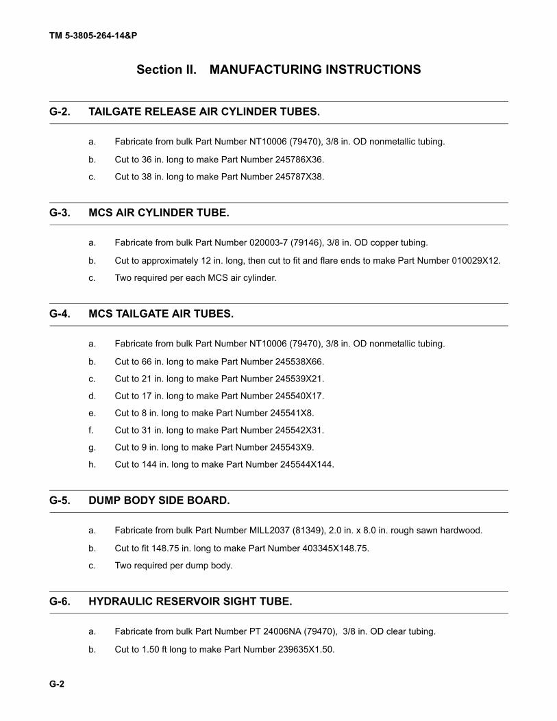
TM 5-3805-264-14&P
G-2
Section II. MANUFACTURING INSTRUCTIONS
G-2. TAILGATE RELEASE AIR CYLINDER TUBES.
a. Fabricate from bulk Part Number NT10006 (79470), 3/8 in. OD nonmetallic tubing.
b. Cut to 36 in. long to make Part Number 245786X36.
c. Cut to 38 in. long to make Part Number 245787X38.
G-3. MCS AIR CYLINDER TUBE.
a. Fabricate from bulk Part Number 020003-7 (79146), 3/8 in. OD copper tubing.
b. Cut to approximately 12 in. long, then cut to fit and flare ends to make Part Number 010029X12.
c. Two required per each MCS air cylinder.
G-4. MCS TAILGATE AIR TUBES.
a. Fabricate from bulk Part Number NT10006 (79470), 3/8 in. OD nonmetallic tubing.
b. Cut to 66 in. long to make Part Number 245538X66.
c. Cut to 21 in. long to make Part Number 245539X21.
d. Cut to 17 in. long to make Part Number 245540X17.
e. Cut to 8 in. long to make Part Number 245541X8.
f. Cut to 31 in. long to make Part Number 245542X31.
g. Cut to 9 in. long to make Part Number 245543X9.
h. Cut to 144 in. long to make Part Number 245544X144.
G-5. DUMP BODY SIDE BOARD.
a. Fabricate from bulk Part Number MILL2037 (81349), 2.0 in. x 8.0 in. rough sawn hardwood.
b. Cut to fit 148.75 in. long to make Part Number 403345X148.75.
c. Two required per dump body.
G-6. HYDRAULIC RESERVOIR SIGHT TUBE.
a. Fabricate from bulk Part Number PT 24006NA (79470), 3/8 in. OD clear tubing.
b. Cut to 1.50 ft long to make Part Number 239635X1.50.

TM 5-3805-264-14&P
G-3/(G-4 Blank)
G-7. HYDRAULIC CYLINDER DISASSEMBLY TOOL.
1. Fabricate from .020 in. shim stock.2. All dimensions are approximate.3. Four required.
1.00 in. (25.4 mm)
3.00 in.(76.2 mm)
.020 in.(.51 mm)
.50 in.(12.7 mm)


TM 5-3805-264-14&P
H-1
APPENDIX HTORQUE LIMITS
H-1. SCOPE.
This appendix lists standard torque values, as shown in Table H-1, and provides general information forapplying torque. Special torque values and tightening sequences are indicated in the maintenance procedures forapplicable components.
H-2. GENERAL.
a. Always use the torque values listed in Table H-1 when the maintenance procedure does not give aspecific torque value.
b. Unless otherwise indicated, standard torque tolerance shall be ±10%.c. Torque values listed are based on clean, dry threads. Reduce torque by 10% when engine oil is
used as a lubricant. Reduce torque by 20% if new plated capscrews are used.d. Capscrews threaded into aluminum may require reductions in torque of 30% or more of Grade 5
capscrew torque. Capscrew threaded into aluminum must also attain two capscrew diameters of thread engage-ment.
CAUTION
If replacement capscrews are of higher grade than originally supplied, use torquespecifications for the original. This will prevent equipment damage due to over-torquing.

TM 5-3805-264-14&P
H-2
Table H-1. Torque Limits.
Current Usage Much Used Much Used Used at Times Used at Times
Quality ofMaterial
Indeterminate MinimumCommercial
MediumCommercial
BestCommercial
SAE Grade Number 1 or 2 5 6 or 7 8
Capscrew HeadMarkings
Manufacturer’smarks may vary
These are allSAE Grade 5(3 line)
Capscrew Body SizeInches - Thread
Torquelb.-ft. (N•m)
Torquelb.-ft. (N•m)
Torquelb.-ft. (N•m)
Torquelb.-ft. (N•m)
1/4 2028
5 (7)6 (8)
8 (11)10 (14)
10 (14) 12 (16)14 (19)
5/16 1824
11 (15)13 (18)
17 (23)19 (26)
19 (26) 24 (33)27 (37)
3/8 1624
18 (24)20 (27)
31 (42)35 (47)
34 (46) 44 (60)49 (66)
7/16 1420
28 (38)30 (41)
49 (66)55 (75)
55 (75) 70 (95)78 (106)
1/2 1320
39 (53)41 (56)
75 (102)85 (115)
85 (115) 105 (142)120 (163)
9/16 1218
51 (69)55 (75)
110 (149)120 (163)
120 (163) 155 (210)170 (231)
5/8 1118
83 (113)95 (129)
150 (203)170 (231)
167 (226) 210 (285)240 (325)
3/4 1016
105 (142)115 (156)
270 (366)295 (400)
280 (380) 375 (508)420 (569)
7/8 914
160 (217)175 (237)
395 (536)435 (590)
440 (597) 605 (820)675 (915)
1 814
235 (319)250 (339)
590 (800)660 (895)
660 (895) 910 (1234)990 (1342)

TM 5-3805-264-14&P
I-1
APPENDIX ITOOL IDENTIFICATION LIST
Section I. INTRODUCTION
I-1. GENERAL.
This appendix lists tools you will need to maintain the dump truck body. This listing is for informationalpurposes only and is not authority to requisition the tools. Common tools are found in the supply catalogs and spe-cial tools are found in the Maintenance Allocation Chart (MAC).
I-2. DEFINITION OF COLUMNS.
a. Column (1) - Item Number (No.). This number is assigned to the entry in the listing and is refer-enced in the “Initial Setup” of maintenance paragraphs or narrative instructions to identify the tool needed (e.g.,General mechanic’s tool kit, Item 8, Appendix I).
b. Column (2) - Item Name. Indicates the tool or tool set name and, if required, a description to iden-tify the tool.
c. Column (3) - National Stock Number. This is the National Stock Number (NSN) assigned to thetool. Use it to request or requisition the tool.
d. Column (4) - (CAGEC) Part Number. When no NSN is available, a Commercial and GovernmentEntity Code (CAGEC) followed by a part number will be used where possible.
e. Column (5) - Reference. Indicates the technical manual or supply catalog in which the tool can befound.
Section II. TOOL IDENTIFICATION LIST
(1)
ItemNo.
(2)
ItemName
(3)
NationalStock Number
(4)
(CAGEC)Part Number
(5)
Reference
1 Cap and Plug Set 5340-00-450-5718 (19207) 10935405
2 Gun, Air Blow 4940-00-333-5541 (58536) A-A-55543 TY2 CL1 STA
SC 4910-95-CL-A74
3 Multimeter, Digital 6625-00-519-0112 (81349) ANPRM15 SC 4910-95-CL-A74
4 Pan, Drain 4910-00-387-9592 (36540) 17942 SC 4910-95-CL-A74
5 Pliers, Retaining Ring:internal, 3.062-6.250 in.
5120-00-293-0186 (19207) 7082060
6 Sling, Nylon 2835-01-078-2081 (91796) 4-8FTX2IN
7 Soldering Gun 3439-00-618-6623 (58536) A-A-59307-1A1B
SC 4910-95-CL-A74
8 Tool Kit, GeneralMechanic’s, Automotive
5180-00-177-7033 (50980)SC 5180-90-CL-N26
SC 5180-90-CL-N26

TM 5-3805-264-14&P
I-2
Section II. TOOL IDENTIFICATION LIST (Con’t)
(1)
ItemNo.
(2)
ItemName
(3)
NationalStock Number
(4)
(CAGEC)Part Number
(5)
Reference
9 Vise, Machinist’s 5120-00-293-1439 (79416) 504M2 SC 4910-95-CL-A74
10 Wrench, Adjustable:0-3 5/8 in. jaw opening
5120-00-264-3793 (24617) 2117080 SC 4910-95-CL-A74
11 Wrench, Torque:1/2 in. drive, 0-175 lb.-ft.capacity
5120-00-640-6364 (58635) A-A-2411 SC 4910-95-CL-A74
12 Wrench, Torque:3/4 in. drive, 0-600 lb.-ft.capacity
5120-01-355-1773 (55719) TE602A SC 4910-95-CL-A72
13 Wrench Set, Socket:3/4 in. drive
5120-00-204-1999 (81348) GGG-W-641 SC 4910-95-CL-A72

TM 5-3805-264-14&P
J-1
APPENDIX JLUBRICATION INSTRUCTIONS
J-1. GENERAL.
NOTE• These instructions are mandatory.• Lubrication of M917A1, M917A1 w/MCS, M917A2, and M917A2 w/MCS chassis is
in TM 9-2320-363-10 or TM 9-2320-302-10 and TM 9-2320-363-20 or TM 9-2320-302-20.
a. The M917A1, M917A1 w/MCS, M917A2, and M917A2 w/MCS Dump Truck Body must receivelubrication with approved lubricants at recommended intervals in order to be mission-ready at all times.
b. Hydraulic oil/filter are changed by Unit Maintenance annually.c. The Lubrication Chart shows lubrication points, items to be lubricated, the required lubricants,
and recommended intervals for lubrication. Any special lubrication instructions required for specific compo-nents are contained in the NOTES section of the chart.
d. The KEY provides information needed to select the proper lubricant for various temperatureranges and uses, and identifies the capacities and intervals.
e. Recommended intervals are based on normal conditions of operation, temperature, and humid-ity. When operating under extreme conditions, lubricants should always be changed more frequently. When indoubt, notify your supervisor.
J-2. SPECIFIC LUBRICATION INSTRUCTIONS.
a. Keep all lubricants in a closed container and store in a clean, dry place away from extreme heat.Keep container covers clean and do not allow dust, dirt, or other foreign material to mix with lubricants. Keeplubrication equipment clean and ready for use.
b. Maintain a record of lubrication performed and report any problems noted during lubrication.Refer to DA Pam 738-750 for maintenance forms and procedures to record and report any findings.
c. Keep all external parts of equipment not requiring lubrication free of lubricants. After lubrication,wipe off excess lubricant to prevent accumulation of foreign matter.
d. Refer to FM 9-207 for lubrication instructions in cold weather.

TM 5-3805-264-14&P
J-2
LUBRICATION CHART
TRUCK, DUMP, HEAVY, BODYM917A1
(NSN 3805-01-431-1165)M917A1 W/MCS
(NSN 3805-01-432-8249)M917A2
(NSN 3805-01-448-7442)M917A2 W/MCS
(NSN 3805-01-448-6963)
This Lubrication Chart is for operator/crew (C) andUnit Maintenance (O). Lubrication intervals (on-con-dition or hard time) are based on normal operation.Lubricate more during constant use and less duringinactive periods. Use correct grade of lubricant forseasonal temperature expected.For equipment under manufacturer's warranty, hardtime oil service intervals shall be followed. Intervalsshall be shortened if lubricants are known to be con-taminated or if operation is under adverse condi-tions (e.g., longer than usual operating hours,extended idling periods, extreme dust, etc.).
WARNING
Dry cleaning solvent MIL-PRF-680 Type III is anenvironmentally compliant and low toxic mate-rial. However, it may be irritating to the eyes andskin. The use of protective gloves and gogglesis suggested. Use in well-ventilated area. Keepaway from open flame and other sources of igni-tion.
Clean area around lubrication points with dry clean-ing solvent (Item 5, Appendix F) or equivalentbefore lubricating equipment. After lubrication, wipeoff excess lubricant to prevent accumulation of for-eign matter.
Before you start your lubrication service:
ALWAYS
a. Clean area around lubrication point beforelubricating.
b. Use the Lubrication Chart as your guide.
NEVER
a. Use wrong type/grade lubricant.
b. Use too much lubricant.
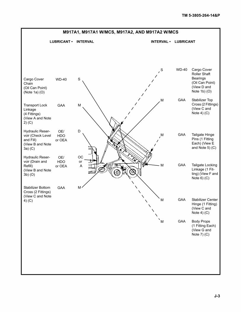
TM 5-3805-264-14&P
J-3
M917A1, M917A1 W/MCS, M917A2, AND M917A2 W/MCS
LUBRICANT • INTERVAL INTERVAL • LUBRICANT
S
M
D
OC or A
M
S
M
M
M
M
M
WD-40
GAA
GAA
GAA
GAA
GAA
WD-40
GAA
OE/HDO
or OEA
OE/HDO
or OEA
GAA
Cargo Cover Roller Shaft Bearings(Oil Can Point) (View D and Note 1b) (O)
Stabilizer Top Cross (2 Fittings) (View C and Note 4) (C)
Tailgate Hinge Pins (1 Fitting Each) (View E and Note 5) (C)
Tailgate Locking Linkage (1 Fit-ting) (View F and Note 6) (C)
Stabilizer Center Hinge (1 Fitting) (View C and Note 4) (C)
Body Props(1 Fitting Each)(View G and Note 7) (C)
Cargo Cover Chain(Oil Can Point)(Note 1a) (O)
Transport Lock Linkage(4 Fittings)(View A and Note 2) (C)
Hydraulic Reser-voir (Check Level and Fill)(View B and Note 3a) (C)
Hydraulic Reser-voir (Drain and Refill)(View B and Note 3b) (O)
Stabilizer Bottom Cross (2 Fittings) (View C and Note 4) (C)

TM 5-3805-264-14&P
J-4
- KEY -
Expected Temperatures*
Lubricant/Component
RefillCapacity
+6°F to +122°F(-14°C to +50°C)
-4°F to +50°F(-20°C to +10°C)
-67°F to +32°F(-55°C to 0°C)
Intervals
OE/HDO(MIL-L-2104)
Lubricating Oil, ICE, Tactical
OEA(MIL-L-46167)
Lubricating Oil, ICE, Arctic• Hydraulic Reser-
voir12.75 gal.
(48.2 l)
OE/HDO 10 OE/HDO 10
OEA
D - DailyM-MonthlyS-Semi-
annualOC-On
Condition
GAA(MIL-G-10924)Grease, Automotive and Artillery• Body Props• Stabilizer• Transport Lock
Linkage• Tailgate Hinge
Pins• Tailgate Locking
Linkage
As Required
ALL TEMPERATURES
WD-40Corrosion Preventive• Cargo Cover
Chain• Cargo Cover
Roller Shaft Bear-ings
As Required
ALL TEMPERATURES
* For arctic operation, refer to FM 9-207.

TM 5-3805-264-14&P
J-5
A TRANSPORT LOCK LINKAGE
B HYDRAULIC RESERVOIR
GAA
GAA
GAA
OIL FILTERELEMENT
SIGHTTUBE
FILL CAP (OE/HDO OR OEA) OILLEVELDECAL
OIL FILTERHOUSING
DRAIN TUBEAND CAP

TM 5-3805-264-14&P
J-6
C STABILIZER
D CARGO COVER
E TAILGATE HINGE PINS
BOTTOM CROSSFITTINGS (GAA)
TOP CROSSFITTINGS (GAA)
CENTERHINGEFITTING(GAA)
ROLLER SHAFTBEARINGS (WD-40)
GAA

TM 5-3805-264-14&P
J-7
F TAILGATE LOCKING LINKAGE
G BODY PROPS
GAA
GAA

TM 5-3805-264-14&P
J-8
NOTES:
1. CARGO COVER.
a. Semiannually, remove chain cover. Clean chain as required and lubricate sparingly with corro-sion preventive. Install chain cover (paragraph 4-66).
b. Semiannually, lubricate roller shaft bearings at roll-up bar mounting brackets. Apply corrosionpreventive sparingly.
2. TRANSPORT LOCK LINKAGE.
a. Monthly, raise dump body and support on body props (paragraph 2-15). Apply GAA to four lubri-cation fittings on linkage. Remove dump body from body props and lower.
b. Remove locking pin and operate transport lock. Reinstall locking pin with transport lock at 3o’clock position (paragraph 2-2).
3. HYDRAULIC RESERVOIR.
WARNING
To prevent burns, use caution when removing fill cap of hydraulic reservoir whenhydraulic fluid is hot. Avoid contact with hot hydraulic oil. Use extreme care whenfilling, sampling or draining hydraulic oil. Failure to follow this warning may resultin injury to personnel.
a. Daily, with dump body down, vehicle parked on level ground, and engine off, check sight tube todetermine level of hydraulic oil in reservoir. Level should be even with FULL mark on oil level decal. If low,remove fill cap, remove any debris from strainer, and clean fill cap and strainer with a clean rag (Item 16,Appendix F). Add OE/HDO or OEA through fill cap opening to bring oil level up to FULL mark. DO NOT overfill.
NOTE
• If reservoir must be filled while dump body is raised and supported on bodyprops, level of oil should be at bottom of sight tube.
• Whenever hydraulic oil filter service indicator shows RED, hydraulic oil filterelement must be replaced.
b. Annually, with dump body down, remove cap from drain tube on underside of reservoir and drainall oil. Remove and clean fill cap and strainer. Install strainer (paragraph 4-74). Replace hydraulic oil filter ele-ment (paragraph 4-75). Clean drain plug and install. Fill reservoir with OE/HDO or OEA until level in sight tubeis at FULL mark on oil level decal. DO NOT overfill.
4. STABILIZER. Monthly, raise dump body and support on body props (paragraph 2-15). Apply GAA to fivelubrication fittings on stabilizer. Remove dump body from body props and lower.
5. TAILGATE HINGE PINS. Monthly, apply GAA to each tailgate hinge pin lubrication fitting.
6. TAILGATE LOCKING LINKAGE. Monthly, apply GAA to tailgate locking linkage lubrication fitting.
7. BODY PROPS. Semiannually, raise dump body and support on body props (paragraph 2-15). Apply GAAto each body prop lubrication fitting.

TM 5-3805-264-14&P
Index 1
INDEXSubject Paragraph Page
AAbbreviations, Official Nomenclature, Names, and Designations . . . . . . . . . . . . . . 1-5 1-2Adhesives, Application of . . . . . . . . . . . . . . . . . . . . . . . . . . . . . . . . . . . . . . . . . . . . 4-15 4-7Adjusting:
MCS Gate Openings (M917A1 w/MCS and M917A2 w/MCS) . . . . . . . . . . . . . 2-12 2-37Tailgate Opening . . . . . . . . . . . . . . . . . . . . . . . . . . . . . . . . . . . . . . . . . . . . . . . . 2-11 2-36
Administrative Storage, Definition of . . . . . . . . . . . . . . . . . . . . . . . . . . . . . . . . . . . . 4-79 4-149Air Cylinder Repair, Tailgate Release/MCS . . . . . . . . . . . . . . . . . . . . . . . . . . . . . . . 4-58 4-87Air Lines and Fittings Replacement, Tailgate Release/MCS . . . . . . . . . . . . . . . . . . 4-59 4-91Antiseize Tape . . . . . . . . . . . . . . . . . . . . . . . . . . . . . . . . . . . . . . . . . . . . . . . . . . . . . 4-22 4-10Application of Adhesives . . . . . . . . . . . . . . . . . . . . . . . . . . . . . . . . . . . . . . . . . . . . . 4-15 4-7Army Materiel, Destruction to Prevent Enemy Use . . . . . . . . . . . . . . . . . . . . . . . . . 1-3 1-1Assembly Instructions, Disassembly and . . . . . . . . . . . . . . . . . . . . . . . . . . . . . . . . 4-13 4-6
BBeacon Warning Light Wiring Harness Maintenance . . . . . . . . . . . . . . . . . . . . . . . 4-45 4-49Body Prop Replacement . . . . . . . . . . . . . . . . . . . . . . . . . . . . . . . . . . . . . . . . . . . . . 4-61 4-95Body Props, Operating . . . . . . . . . . . . . . . . . . . . . . . . . . . . . . . . . . . . . . . . . . . . . . 2-15 2-42Body Up and Transport Lock Switches Wiring Harness Maintenance . . . . . . . . . . 4-44 4-47Body Up Switch Replacement . . . . . . . . . . . . . . . . . . . . . . . . . . . . . . . . . . . . . . . . 4-38 4-33Bracket Replacement, Shovel . . . . . . . . . . . . . . . . . . . . . . . . . . . . . . . . . . . . . . . . . 4-70 4-115
CCab Shield Replacement . . . . . . . . . . . . . . . . . . . . . . . . . . . . . . . . . . . . . . . . . . . . 4-62 4-96Cab-Mounted Controls and Indicators . . . . . . . . . . . . . . . . . . . . . . . . . . . . . . . . . . 2-1 2-1Care and Handling, Safety . . . . . . . . . . . . . . . . . . . . . . . . . . . . . . . . . . . . . . . . . . . 1-8 1-2Care of Equipment in Administrative Storage . . . . . . . . . . . . . . . . . . . . . . . . . . . . . 4-82 4-151Cargo Cover Repair . . . . . . . . . . . . . . . . . . . . . . . . . . . . . . . . . . . . . . . . . . . . . . . . 5-3 5-9Cargo Cover:
Chain and Sprockets Replacement . . . . . . . . . . . . . . . . . . . . . . . . . . . . . . . . . 4-66 4-106Crank Assembly Maintenance . . . . . . . . . . . . . . . . . . . . . . . . . . . . . . . . . . . . . 4-65 4-103Operating . . . . . . . . . . . . . . . . . . . . . . . . . . . . . . . . . . . . . . . . . . . . . . . . . . . . . 2-14 2-38Replacement . . . . . . . . . . . . . . . . . . . . . . . . . . . . . . . . . . . . . . . . . . . . . . . . . . 4-64 4-101Support Frame and Roll-Up Bar Replacement . . . . . . . . . . . . . . . . . . . . . . . . . 4-67 4-110
Characteristics, Capabilities, and Features, Equipment . . . . . . . . . . . . . . . . . . . . . 1-10 1-4Cleaning . . . . . . . . . . . . . . . . . . . . . . . . . . . . . . . . . . . . . . . . . . . . . . . . . . . . . . . . . 3-5 3-9Cleaning Instructions . . . . . . . . . . . . . . . . . . . . . . . . . . . . . . . . . . . . . . . . . . . . . . . 4-9 4-4Cold Weather, Operation in . . . . . . . . . . . . . . . . . . . . . . . . . . . . . . . . . . . . . . . . . . . 2-18 2-43Common Components and Miscellaneous Items, Procedures for . . . . . . . . . . . . . 4-83 4-152

TM 5-3805-264-14&P
Index 2
INDEX (Con’t)Subject Paragraph Page
C (Con’t)Common Tools and Equipment . . . . . . . . . . . . . . . . . . . . . . . . . . . . . . . . . . . . . . . . 4-1 4-1
Compression Fittings, Tubes and . . . . . . . . . . . . . . . . . . . . . . . . . . . . . . . . . . . . . . 4-23 4-11
Controlled Spreading (M917A1 w/MCS and M917A2 w/MCS) . . . . . . . . . . . . . . . . 2-13 2-38
Controls and Indicators:Cab-Mounted . . . . . . . . . . . . . . . . . . . . . . . . . . . . . . . . . . . . . . . . . . . . . . . . . . 2-1 2-1External . . . . . . . . . . . . . . . . . . . . . . . . . . . . . . . . . . . . . . . . . . . . . . . . . . . . . . 2-2 2-3
Corrosion Prevention and Control (CPC) . . . . . . . . . . . . . . . . . . . . . . . . . . . . . . . . 1-9 1-3
Cylinder Support Frame Replacement . . . . . . . . . . . . . . . . . . . . . . . . . . . . . . . . . . 5-2 5-7
DData Plate Replacement . . . . . . . . . . . . . . . . . . . . . . . . . . . . . . . . . . . . . . . . . . . . . 4-69 4-114
Data:Equipment . . . . . . . . . . . . . . . . . . . . . . . . . . . . . . . . . . . . . . . . . . . . . . . . . . . . 1-14 1-11Lubrication . . . . . . . . . . . . . . . . . . . . . . . . . . . . . . . . . . . . . . . . . . . . . . . . . . . . Table 4-1 4-17
Decals and Stencils, Location and Contents of . . . . . . . . . . . . . . . . . . . . . . . . . . . . 1-12 1-8
Destruction of Army Materiel to Prevent Enemy Use . . . . . . . . . . . . . . . . . . . . . . . 1-3 1-1
Differences Between Models . . . . . . . . . . . . . . . . . . . . . . . . . . . . . . . . . . . . . . . . . 1-13 1-11
Disassembly and Assembly Instructions . . . . . . . . . . . . . . . . . . . . . . . . . . . . . . . . . 4-13 4-6
Dump Body and Stabilizer Replacement . . . . . . . . . . . . . . . . . . . . . . . . . . . . . . . . . 5-1 5-1
Dump Body:Loading . . . . . . . . . . . . . . . . . . . . . . . . . . . . . . . . . . . . . . . . . . . . . . . . . . . . . . . 2-8 2-28Preparing to Load . . . . . . . . . . . . . . . . . . . . . . . . . . . . . . . . . . . . . . . . . . . . . . . 2-7 2-27Principles of Operation . . . . . . . . . . . . . . . . . . . . . . . . . . . . . . . . . . . . . . . . . . . 1-16 1-13
Dumping Load . . . . . . . . . . . . . . . . . . . . . . . . . . . . . . . . . . . . . . . . . . . . . . . . . . . . . 2-10 2-30
EElectrical System, Principles of Operation . . . . . . . . . . . . . . . . . . . . . . . . . . . . . . . 1-15 1-13
Electrical:Ground Points . . . . . . . . . . . . . . . . . . . . . . . . . . . . . . . . . . . . . . . . . . . . . . . . . . 4-20 4-9Repair . . . . . . . . . . . . . . . . . . . . . . . . . . . . . . . . . . . . . . . . . . . . . . . . . . . . . . . . 4-27 4-12
Equipment:Characteristics, Capabilities, and Features . . . . . . . . . . . . . . . . . . . . . . . . . . . 1-10 1-5Common Tools and . . . . . . . . . . . . . . . . . . . . . . . . . . . . . . . . . . . . . . . . . . . . . . 4-1 4-1Data . . . . . . . . . . . . . . . . . . . . . . . . . . . . . . . . . . . . . . . . . . . . . . . . . . . . . . . . . 1-14 1-11Special Tools . . . . . . . . . . . . . . . . . . . . . . . . . . . . . . . . . . . . . . . . . . . . . . . . . . . 4-2 4-1Support . . . . . . . . . . . . . . . . . . . . . . . . . . . . . . . . . . . . . . . . . . . . . . . . . . . . . . . 4-2 4-1TMDE . . . . . . . . . . . . . . . . . . . . . . . . . . . . . . . . . . . . . . . . . . . . . . . . . . . . . . . . 4-2 4-1

TM 5-3805-264-14&P
Index 3
INDEX (Con’t)Subject Paragraph Page
E (Con’t)Explanation of Table Entries:
Operator PMCS . . . . . . . . . . . . . . . . . . . . . . . . . . . . . . . . . . . . . . . . . . . . . . . . 2-4 2-7Unit PMCS . . . . . . . . . . . . . . . . . . . . . . . . . . . . . . . . . . . . . . . . . . . . . . . . . . . . 4-29 4-13
External Controls and Indicators . . . . . . . . . . . . . . . . . . . . . . . . . . . . . . . . . . . . . . . 2-2 2-3
FFluid Disposal . . . . . . . . . . . . . . . . . . . . . . . . . . . . . . . . . . . . . . . . . . . . . . . . . . . . . 4-24 4-11
GGeneral Lubrication Procedures . . . . . . . . . . . . . . . . . . . . . . . . . . . . . . . . . . . . . . . 4-30 4-14General PMCS Procedures:
Operator . . . . . . . . . . . . . . . . . . . . . . . . . . . . . . . . . . . . . . . . . . . . . . . . . . . . . . 2-5 2-8Unit . . . . . . . . . . . . . . . . . . . . . . . . . . . . . . . . . . . . . . . . . . . . . . . . . . . . . . . . . . 4-31 4-15
Ground Points, Electrical . . . . . . . . . . . . . . . . . . . . . . . . . . . . . . . . . . . . . . . . . . . . . 4-20 4-9
HHeat Shrinkable Tubing . . . . . . . . . . . . . . . . . . . . . . . . . . . . . . . . . . . . . . . . . . . . . . 4-19 4-8Hoses:
Tagging Wires and . . . . . . . . . . . . . . . . . . . . . . . . . . . . . . . . . . . . . . . . . . . . . . 4-17 4-8Hydraulic System, Principles of Operation . . . . . . . . . . . . . . . . . . . . . . . . . . . . . . . 1-17 1-16
Hydraulic:Control Lever Cable Replacement . . . . . . . . . . . . . . . . . . . . . . . . . . . . . . . . . . 4-73 4-127Control Lever Replacement . . . . . . . . . . . . . . . . . . . . . . . . . . . . . . . . . . . . . . . 4-72 4-117Cylinder Repair . . . . . . . . . . . . . . . . . . . . . . . . . . . . . . . . . . . . . . . . . . . . . . . . . 5-7 5-23Cylinder Replacement . . . . . . . . . . . . . . . . . . . . . . . . . . . . . . . . . . . . . . . . . . . 5-6 5-20Hoses and Fittings Replacement . . . . . . . . . . . . . . . . . . . . . . . . . . . . . . . . . . . 4-74 4-136Oil Filter Element Replacement . . . . . . . . . . . . . . . . . . . . . . . . . . . . . . . . . . . . 4-77 4-145Oil Filter Service Indicator Gage Replacement . . . . . . . . . . . . . . . . . . . . . . . . 4-78 4-147Pump Repair . . . . . . . . . . . . . . . . . . . . . . . . . . . . . . . . . . . . . . . . . . . . . . . . . . . 5-5 5-14Pump Replacement . . . . . . . . . . . . . . . . . . . . . . . . . . . . . . . . . . . . . . . . . . . . . 5-4 5-10Reservoir Repair . . . . . . . . . . . . . . . . . . . . . . . . . . . . . . . . . . . . . . . . . . . . . . . . 4-76 4-143Reservoir Replacement . . . . . . . . . . . . . . . . . . . . . . . . . . . . . . . . . . . . . . . . . . 4-75 4-140
IInspection Instructions . . . . . . . . . . . . . . . . . . . . . . . . . . . . . . . . . . . . . . . . . . . . . . 4-12 4-6Instructions:
Cleaning . . . . . . . . . . . . . . . . . . . . . . . . . . . . . . . . . . . . . . . . . . . . . . . . . . . . . . 4-9 4-4Disassembly and Assembly . . . . . . . . . . . . . . . . . . . . . . . . . . . . . . . . . . . . . . . 4-13 4-6Inspection . . . . . . . . . . . . . . . . . . . . . . . . . . . . . . . . . . . . . . . . . . . . . . . . . . . . . 4-12 4-6Lubrication . . . . . . . . . . . . . . . . . . . . . . . . . . . . . . . . . . . . . . . . . . . . . . . . . . . . 4-14 4-6Servicing . . . . . . . . . . . . . . . . . . . . . . . . . . . . . . . . . . . . . . . . . . . . . . . . . . . . . . 4-6 4-2

TM 5-3805-264-14&P
Index 4
INDEX (Con’t)Subject Paragraph Page
LLights Replacement:
Marker Clearance Light . . . . . . . . . . . . . . . . . . . . . . . . . . . . . . . . . . . . . . . . . . 4-41 4-37Taillight . . . . . . . . . . . . . . . . . . . . . . . . . . . . . . . . . . . . . . . . . . . . . . . . . . . . . . . 4-40 4-36
Lights Wiring Harness Maintenance . . . . . . . . . . . . . . . . . . . . . . . . . . . . . . . . . . . . 4-46 4-52Lines and Ports . . . . . . . . . . . . . . . . . . . . . . . . . . . . . . . . . . . . . . . . . . . . . . . . . . . . 4-21 4-10Load, Dumping . . . . . . . . . . . . . . . . . . . . . . . . . . . . . . . . . . . . . . . . . . . . . . . . . . . . 2-10 2-29Load, Transporting . . . . . . . . . . . . . . . . . . . . . . . . . . . . . . . . . . . . . . . . . . . . . . . . . 2-9 2-28Loading Dump Body . . . . . . . . . . . . . . . . . . . . . . . . . . . . . . . . . . . . . . . . . . . . . . . . 2-8 2-28Location and:
Contents of Decals and Stencils . . . . . . . . . . . . . . . . . . . . . . . . . . . . . . . . . . . . 1-12 1-7Description of Major Components . . . . . . . . . . . . . . . . . . . . . . . . . . . . . . . . . . 1-11 1-5
Lubrication:Data . . . . . . . . . . . . . . . . . . . . . . . . . . . . . . . . . . . . . . . . . . . . . . . . . . . . . . . . . 4-33 4-17Instructions . . . . . . . . . . . . . . . . . . . . . . . . . . . . . . . . . . . . . . . . . . . . . . . . . . . . 4-14 4-6Procedures, General . . . . . . . . . . . . . . . . . . . . . . . . . . . . . . . . . . . . . . . . . . . . 4-30 4-14
MMaintenance Forms, Records, and Reports . . . . . . . . . . . . . . . . . . . . . . . . . . . . . . 1-2 1-1Major Components, Location and Description . . . . . . . . . . . . . . . . . . . . . . . . . . . . 1-11 1-5Mandatory Replacement Parts . . . . . . . . . . . . . . . . . . . . . . . . . . . . . . . . . . . . . . . . 4-34 4-18Marker Clearance Light Replacement . . . . . . . . . . . . . . . . . . . . . . . . . . . . . . . . . . 4-41 4-38MCS:
Adjustment Tube Replacement (M917A1 w/MCS and M917A2 w/MCS) . . . . . 4-60 4-93Air Cylinder Replacement (M917A1 w/MCS and M917A2 w/MCS) . . . . . . . . . 4-56 4-79Air Cylinder Solenoid Assembly Replacement (M917A1 w/MCS
and M917A2 w/MCS) . . . . . . . . . . . . . . . . . . . . . . . . . . . . . . . . . . . . . 4-57 4-82Air Reservoir Replacement (M917A1 w/MCS and M917A2 w/MCS) . . . . . . . . 4-55 4-77Control Unit Maintenance (M917A1 w/MCS and M917A2 w/MCS) . . . . . . . . . 4-42 4-39Gate Replacement (M917A1 w/MCS and M917A2 w/MCS) . . . . . . . . . . . . . . 4-54 4-75Remote Control Repair (M917A1 w/MCS and M917A2 w/MCS) . . . . . . . . . . . 4-43 4-42Tailgate Cover Replacement (M917A1 w/MCS and M917A2 w/MCS) . . . . . . . 4-53 4-73Tailgate Replacement (M917A1 w/MCS and M917A2 w/MCS) . . . . . . . . . . . . 4-52 4-70Tailgate Wiring Harness Maintenance (M917A1 w/MCS and
M917A2 w/MCS) . . . . . . . . . . . . . . . . . . . . . . . . . . . . . . . . . . . . . . . . . 4-48 4-58Mud Flap Replacement . . . . . . . . . . . . . . . . . . . . . . . . . . . . . . . . . . . . . . . . . . . . . . 4-63 4-99
NNames, Designations, Abbreviations, and Official Nomenclature . . . . . . . . . . . . . . 1-5 1-2
OOfficial Nomenclature, Names, Designations, and Abbreviations . . . . . . . . . . . . . . 1-5 1-2

TM 5-3805-264-14&P
Index 5
INDEX (Con’t)Subject Paragraph Page
O (Con’t)Operating:
Body Props . . . . . . . . . . . . . . . . . . . . . . . . . . . . . . . . . . . . . . . . . . . . . . . . . . . . 2-15 2-42Cargo Cover . . . . . . . . . . . . . . . . . . . . . . . . . . . . . . . . . . . . . . . . . . . . . . . . . . . 2-14 2-40
Operation in:Cold Weather . . . . . . . . . . . . . . . . . . . . . . . . . . . . . . . . . . . . . . . . . . . . . . . . . . 2-18 2-43Rainy or Snowy Weather . . . . . . . . . . . . . . . . . . . . . . . . . . . . . . . . . . . . . . . . . 2-17 2-43Windy Weather . . . . . . . . . . . . . . . . . . . . . . . . . . . . . . . . . . . . . . . . . . . . . . . . . 2-16 2-43
Operator:Preventive Maintenance Checks and Services (PMCS) . . . . . . . . . . . . . . . . . Table 2-1 2-10Troubleshooting . . . . . . . . . . . . . . . . . . . . . . . . . . . . . . . . . . . . . . . . . . . . . . . . Table 3-1 3-5Troubleshooting Symptom Index . . . . . . . . . . . . . . . . . . . . . . . . . . . . . . . . . . . 3-3 3-4
PPainting . . . . . . . . . . . . . . . . . . . . . . . . . . . . . . . . . . . . . . . . . . . . . . . . . . . . . . . . . . 4-11 4-5
Parts and Kits, Service Replacement . . . . . . . . . . . . . . . . . . . . . . . . . . . . . . . . . . . 4-25 4-12
PMCS Initial Setup . . . . . . . . . . . . . . . . . . . . . . . . . . . . . . . . . . . . . . . . . . . . . . . . . 4-32 4-16
PMCS Procedures, General:Operator . . . . . . . . . . . . . . . . . . . . . . . . . . . . . . . . . . . . . . . . . . . . . . . . . . . . . . 2-5 2-8Unit . . . . . . . . . . . . . . . . . . . . . . . . . . . . . . . . . . . . . . . . . . . . . . . . . . . . . . . . . . 4-31 4-15
PMCS:Operator . . . . . . . . . . . . . . . . . . . . . . . . . . . . . . . . . . . . . . . . . . . . . . . . . . . . . . Table 2-1 2-10Unit . . . . . . . . . . . . . . . . . . . . . . . . . . . . . . . . . . . . . . . . . . . . . . . . . . . . . . . . . . Table 4-2 4-19
Ports, Lines and . . . . . . . . . . . . . . . . . . . . . . . . . . . . . . . . . . . . . . . . . . . . . . . . . . . 4-21 4-10
Preparation for Storage or Shipment . . . . . . . . . . . . . . . . . . . . . . . . . . . . . . . . . . . . 1-4 1-2
Preparation of Equipment for Administrative Storage . . . . . . . . . . . . . . . . . . . . . . . 4-81 4-149
Preparation of Equipment for Shipment . . . . . . . . . . . . . . . . . . . . . . . . . . . . . . . . . 4-85 4-152
Preparing to Load Dump Body . . . . . . . . . . . . . . . . . . . . . . . . . . . . . . . . . . . . . . . . 2-7 2-27
Preservation of Parts . . . . . . . . . . . . . . . . . . . . . . . . . . . . . . . . . . . . . . . . . . . . . . . . 4-10 4-5
Procedures for Common Components and Miscellaneous Items . . . . . . . . . . . . . . 4-83 4-152
RRainy or Snowy Weather, Operation in . . . . . . . . . . . . . . . . . . . . . . . . . . . . . . . . . . 2-17 2-41
Reflector Replacement . . . . . . . . . . . . . . . . . . . . . . . . . . . . . . . . . . . . . . . . . . . . . . 4-68 4-113
Remote Control Repair, MCS (M917A1 w/MCS and M917A2 w/MCS) . . . . . . . . . 4-43 4-42
Removal of Equipment from Administrative Storage . . . . . . . . . . . . . . . . . . . . . . . 4-84 4-152
Repair Parts . . . . . . . . . . . . . . . . . . . . . . . . . . . . . . . . . . . . . . . . . . . . . . . . . . . . . . 4-3 4-1
Reporting Equipment Improvement Recommendations (EIRs) . . . . . . . . . . . . . . . 1-6 1-2
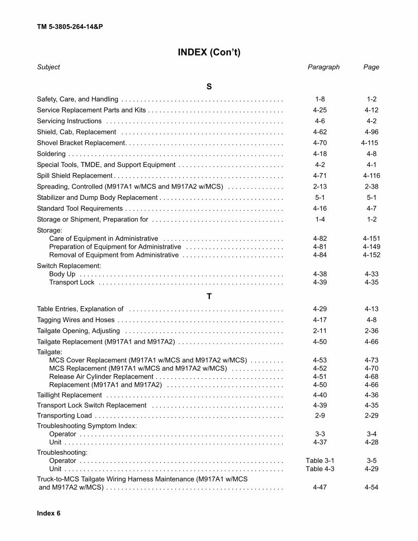
TM 5-3805-264-14&P
Index 6
INDEX (Con’t)Subject Paragraph Page
SSafety, Care, and Handling . . . . . . . . . . . . . . . . . . . . . . . . . . . . . . . . . . . . . . . . . . . 1-8 1-2Service Replacement Parts and Kits . . . . . . . . . . . . . . . . . . . . . . . . . . . . . . . . . . . . 4-25 4-12Servicing Instructions . . . . . . . . . . . . . . . . . . . . . . . . . . . . . . . . . . . . . . . . . . . . . . . 4-6 4-2Shield, Cab, Replacement . . . . . . . . . . . . . . . . . . . . . . . . . . . . . . . . . . . . . . . . . . . 4-62 4-96Shovel Bracket Replacement. . . . . . . . . . . . . . . . . . . . . . . . . . . . . . . . . . . . . . . . . . 4-70 4-115Soldering . . . . . . . . . . . . . . . . . . . . . . . . . . . . . . . . . . . . . . . . . . . . . . . . . . . . . . . . . 4-18 4-8Special Tools, TMDE, and Support Equipment . . . . . . . . . . . . . . . . . . . . . . . . . . . . 4-2 4-1Spill Shield Replacement . . . . . . . . . . . . . . . . . . . . . . . . . . . . . . . . . . . . . . . . . . . . . 4-71 4-116Spreading, Controlled (M917A1 w/MCS and M917A2 w/MCS) . . . . . . . . . . . . . . . 2-13 2-38Stabilizer and Dump Body Replacement . . . . . . . . . . . . . . . . . . . . . . . . . . . . . . . . . 5-1 5-1Standard Tool Requirements . . . . . . . . . . . . . . . . . . . . . . . . . . . . . . . . . . . . . . . . . . 4-16 4-7Storage or Shipment, Preparation for . . . . . . . . . . . . . . . . . . . . . . . . . . . . . . . . . . . 1-4 1-2Storage:
Care of Equipment in Administrative . . . . . . . . . . . . . . . . . . . . . . . . . . . . . . . . 4-82 4-151Preparation of Equipment for Administrative . . . . . . . . . . . . . . . . . . . . . . . . . . 4-81 4-149Removal of Equipment from Administrative . . . . . . . . . . . . . . . . . . . . . . . . . . . 4-84 4-152
Switch Replacement:Body Up . . . . . . . . . . . . . . . . . . . . . . . . . . . . . . . . . . . . . . . . . . . . . . . . . . . . . . 4-38 4-33Transport Lock . . . . . . . . . . . . . . . . . . . . . . . . . . . . . . . . . . . . . . . . . . . . . . . . . 4-39 4-35
TTable Entries, Explanation of . . . . . . . . . . . . . . . . . . . . . . . . . . . . . . . . . . . . . . . . . 4-29 4-13Tagging Wires and Hoses . . . . . . . . . . . . . . . . . . . . . . . . . . . . . . . . . . . . . . . . . . . . 4-17 4-8Tailgate Opening, Adjusting . . . . . . . . . . . . . . . . . . . . . . . . . . . . . . . . . . . . . . . . . . 2-11 2-36Tailgate Replacement (M917A1 and M917A2) . . . . . . . . . . . . . . . . . . . . . . . . . . . . 4-50 4-66Tailgate:
MCS Cover Replacement (M917A1 w/MCS and M917A2 w/MCS) . . . . . . . . . 4-53 4-73MCS Replacement (M917A1 w/MCS and M917A2 w/MCS) . . . . . . . . . . . . . . 4-52 4-70Release Air Cylinder Replacement . . . . . . . . . . . . . . . . . . . . . . . . . . . . . . . . . . 4-51 4-68Replacement (M917A1 and M917A2) . . . . . . . . . . . . . . . . . . . . . . . . . . . . . . . 4-50 4-66
Taillight Replacement . . . . . . . . . . . . . . . . . . . . . . . . . . . . . . . . . . . . . . . . . . . . . . . 4-40 4-36Transport Lock Switch Replacement . . . . . . . . . . . . . . . . . . . . . . . . . . . . . . . . . . . 4-39 4-35Transporting Load . . . . . . . . . . . . . . . . . . . . . . . . . . . . . . . . . . . . . . . . . . . . . . . . . . 2-9 2-29Troubleshooting Symptom Index:
Operator . . . . . . . . . . . . . . . . . . . . . . . . . . . . . . . . . . . . . . . . . . . . . . . . . . . . . . 3-3 3-4Unit . . . . . . . . . . . . . . . . . . . . . . . . . . . . . . . . . . . . . . . . . . . . . . . . . . . . . . . . . . 4-37 4-28
Troubleshooting:Operator . . . . . . . . . . . . . . . . . . . . . . . . . . . . . . . . . . . . . . . . . . . . . . . . . . . . . . Table 3-1 3-5Unit . . . . . . . . . . . . . . . . . . . . . . . . . . . . . . . . . . . . . . . . . . . . . . . . . . . . . . . . . . Table 4-3 4-29
Truck-to-MCS Tailgate Wiring Harness Maintenance (M917A1 w/MCS and M917A2 w/MCS) . . . . . . . . . . . . . . . . . . . . . . . . . . . . . . . . . . . . . . . . . . . . . . . 4-47 4-54

TM 5-3805-264-14&P
Index 7/(Index 8 Blank)
INDEX (Con’t)Subject Paragraph Page
T (Con’t)Tubes and Compression Fittings . . . . . . . . . . . . . . . . . . . . . . . . . . . . . . . . . . . . . . 4-23 4-11Tubing, Heat Shrinkable . . . . . . . . . . . . . . . . . . . . . . . . . . . . . . . . . . . . . . . . . . . . . 4-19 4-8
UUnit:
PMCS . . . . . . . . . . . . . . . . . . . . . . . . . . . . . . . . . . . . . . . . . . . . . . . . . . . . . . . . Table 4-2 4-19Troubleshooting . . . . . . . . . . . . . . . . . . . . . . . . . . . . . . . . . . . . . . . . . . . . . . . . Table 4-3 4-29Troubleshooting Symptom Index . . . . . . . . . . . . . . . . . . . . . . . . . . . . . . . . . . . 4-37 4-28
WWarranty Information . . . . . . . . . . . . . . . . . . . . . . . . . . . . . . . . . . . . . . . . . . . . . . . . 1-7 1-2Welding . . . . . . . . . . . . . . . . . . . . . . . . . . . . . . . . . . . . . . . . . . . . . . . . . . . . . . . . . . 4-26 4-12Windy Weather, Operation in . . . . . . . . . . . . . . . . . . . . . . . . . . . . . . . . . . . . . . . . . 2-16 2-43Wires and Hoses, Tagging . . . . . . . . . . . . . . . . . . . . . . . . . . . . . . . . . . . . . . . . . . . 4-17 4-8Wiring Diagrams . . . . . . . . . . . . . . . . . . . . . . . . . . . . . . . . . . . . . . . . . . . . . . . . . . . 4-49 4-62Wiring Harness Maintenance:
Beacon Warning Light . . . . . . . . . . . . . . . . . . . . . . . . . . . . . . . . . . . . . . . . . . . . 4-45 4-49Body Up and Transport Lock Switches . . . . . . . . . . . . . . . . . . . . . . . . . . . . . . . 4-44 4-47Lights . . . . . . . . . . . . . . . . . . . . . . . . . . . . . . . . . . . . . . . . . . . . . . . . . . . . . . . . . 4-46 4-52MCS Tailgate (M917A1 w/MCS and M917A2 w/MCS) . . . . . . . . . . . . . . . . . . . 4-48 4-58Truck-to-MCS Tailgate (M917A1 w/MCS and M917A2 w/MCS) . . . . . . . . . . . . 4-47 4-54
Work Safety . . . . . . . . . . . . . . . . . . . . . . . . . . . . . . . . . . . . . . . . . . . . . . . . . . . . . . . 4-8 4-4


RECOMMENDED CHANGES TO PUBLICATIONS AND BLANK FORMS For use of this form, see AR 25-30; the proponent agency is ODISC4.
Use Part II (reverse) for Repair Parts and Special Tool Lists (RPSTL) and Supply Catalogs/Supply Manuals (SC/SM).
DATE
Date you filled out this form.
TO: (Forward to proponent of publication or form) (Include ZIP Code) U.S. Army TACOM Life Cycle Management Command ATTN: AMSTA-LCL-MPP/TECH PUBS 6501 E. 11 Mile Road, Warren, MI 48397-5000
FROM: (Activity and location) (Include ZIP Code)
Your mailing address
PART I – ALL PUBLICATIONS (EXCEPT RPSTL AND SC/SM) AND BLANK FORMS PUBLICATION/FORM NUMBER DATE Title
Operator’s, Unit, DS, & GS Maintenance Manual
TM 5-3805-264-14&P 30 December 2005 Manual w/ RPSTL for M917A1, M917A1 w/ MCS,
ITEMNO.
PAGENO.
PARA-GRAPH
LINENO. *
FIGURENO.
TABLENO.
RECOMMENDED CHANGES AND REASON (Provide exact wording of recommended changes, if possible).
*Reference to line numbers within the paragraph or subparagraph. TYPED NAME, GRADE OR TITLE
Your Name
TELEPHONE EXCHANGE/AUTOVON, PLUS EXTENSION SIGNATURE
Your Signature
DA FORM 2028, FEB 74 REPLACES DA FORM 2028, 1 DEC 68, WHICH WILL BE USED. USAPPC V3.00
M917A2, and M917A2 w/MCS
Change 1

TO: (Forward direct to addressee listed in publication) U.S. Army TACOM Life Cycle Management Command ATTN: AMSTA-LCL-MPP/TECH PUBS 6501 E. 11 Mile Road, Warren, MI 48397-5000
FROM: (Activity and location) (Include ZIP Code)
Your address DATEDate you filled out this form
PART II – REPAIR PARTS AND SPECIAL TOOL LISTS AND SUPPLY CATALOGS/SUPPLY MANUALS PUBLICATION NUMBER DATE TITLE M917A1, M917A1 w/MCS,
PAGENO.
COLMNO.
LINENO.
NATIONAL STOCK NUMBER
REFERENCENO.
FIGURENO.
ITEMNO.
TOTAL NO.OF MAJOR
ITEMSSUPPORTED
RECOMMENDED ACTION
PART III – REMARKS (Any general remarks or recommendations, or suggestions for improvement of publications and blank forms. Additional blank sheets may be used if more space is needed.)
TYPED NAME, GRADE OR TITLE
Your Name
TELEPHONE EXCHANGE/AUTOVON, PLUS EXTENSION SIGNATURE
Your Signature
USAPPC V3.00
SAMPLE
TM 5-3805-264-14&P 30 December 2005 M917A2 and M917A2 w/MCS
Change 1

RECOMMENDED CHANGES TO PUBLICATIONS AND BLANK FORMS
For use of this form, see AR 25-30; the proponent agency is ODISC4.
Use Part II (reverse) for Repair Parts and Special Tool Lists (RPSTL) and Supply Catalogs/Supply Manuals (SC/SM).
DATE
U.S. Army TACOM Life Cycle Management Command ATTN: AMSTA-LCL-MPP/TECH PUBS 6501 E. 11 Mile Road, Warren, MI 48397-5000
FROM: (Activity and location) (Include ZIP Code)
PART I – ALL PUBLICATIONS (EXCEPT RPSTL AND SC/SM) AND BLANK FORMS PUBLICATION/FORM NUMBER DATE TITLE M917A1, M917A1 w/MCS, M917A2, and
TM 5-3805-264-14&P 30 December 2005 M917A2 w/MCSITEMNO.
PAGENO.
PARA-GRAPH
LINENO. *
FIGURENO.
TABLENO.
RECOMMENDED CHANGES AND REASON (Provide exact wording of recommended changes, if possible).
*Reference to line numbers within the paragraph or subparagraph. TYPED NAME, GRADE OR TITLE TELEPHONE EXCHANGE/AUTOVON, PLUS
EXTENSIONSIGNATURE
DA FORM 2028, FEB 74 REPLACES DA FORM 2028, 1 DEC 68, WHICH WILL BE USED. USAPPC V3.00
TO: (Forward to proponent of publication or form)(Include ZIP Code)
Change 1
TO: (Forward direct to addressee listed in publication) U.S. Army TACOM Life Cycle Management Command ATTN: AMSTA-LCL-MPP/TECH PUBS6501 E. 11 Mile Road, Warren, MI 48397-5000
FROM: (Activity and location) (Include ZIP Code) DATE
PART II – REPAIR PARTS AND SPECIAL TOOL LISTS AND SUPPLY CATALOGS/SUPPLY MANUALS PUBLICATION NUMBER DATE TITLE M917A1, M917A1 w/MCS, M917A2,
PAGENO.
COLMNO.
LINENO.
NATIONAL STOCK NUMBER
REFERENCENO.
FIGURENO.
ITEMNO.
TOTAL NO.OF MAJOR
ITEMSSUPPORTED
RECOMMENDED ACTION
PART III – REMARKS (Any general remarks or recommendations, or suggestions for improvement of publications and blank forms. Additional blank sheets may be used if more space is needed.)
TYPED NAME, GRADE OR TITLE TELEPHONE EXCHANGE/AUTOVON, PLUS EXTENSION SIGNATURE
USAPPC V3.00
TM 5-3805-264-14&P 30 December 2005 and M917A2 w/MCS
Change 1

RECOMMENDED CHANGES TO PUBLICATIONS AND BLANK FORMS
For use of this form, see AR 25-30; the proponent agency is ODISC4.
Use Part II (reverse) for Repair Parts and Special Tool Lists (RPSTL) and Supply Catalogs/Supply Manuals (SC/SM).
DATE
TO: (Forward to proponent of publication or form) (Include ZIP Code) U.S. Army TACOM Life Cycle Management Command ATTN: AMSTA-LCL-MPP/TECH PUBS 6501 E. 11 Mile Road, Warren, MI 48397-5000
FROM: (Activity and location) (Include ZIP Code)
PUBLICATION/FORM NUMBER DATE TITLE M917A1, M917A1 w/MCS, M917A2, TM 5-3805-264-14&P 30 December 2005 and M917A2 w/MCS
ITEM NO.
PAGENO.
PARA-GRAPH
LINE NO. *
FIGURENO.
TABLENO.
RECOMMENDED CHANGES AND REASON (Provide exact wording of recommended changes, if possible).
*Reference to line numbers within the paragraph or subparagraph.
TYPED NAME, GRADE OR TITLE TELEPHONE EXCHANGE/AUTOVON, PLUS EXTENSION
SIGNATURE
DA FORM 2028, FEB 74 REPLACES DA FORM 2028, 1 DEC 68, WHICH WILL BE USED. USAPPC V3.00
Change 1

TO: (Forward direct to addressee listed in publication)U.S. Army TACOM Life Cycle Management Command ATTN: AMSTA-LCL-MPP/TECH PUBS6501 E. 11 Mile Road, Warren, MI 48397-5000
FROM: (Activity and location) (Include ZIP Code) DATE
PART II – REPAIR PARTS AND SPECIAL TOOL LISTS AND SUPPLY CATALOGS/SUPPLY MANUALS PUBLICATION NUMBER DATE TITLE M917A1, M917A1 w/MCS, TM 5-3805-264-14&P 30 December 2005 M917A2, and M917A2 w/ MCS
PAGENO.
COLMNO.
LINENO.
NATIONAL STOCK NUMBER
REFERENCENO.
FIGURENO.
ITEMNO.
TOTAL NO.OF MAJOR
ITEMSSUPPORTED
RECOMMENDED ACTION
PART III – REMARKS (Any general remarks or recommendations, or suggestions for improvement of publications and blank forms. Additional blank sheets may be used if more space is needed.)
TYPED NAME, GRADE OR TITLE TELEPHONE EXCHANGE/AUTOVON, PLUS EXTENSION SIGNATURE
USAPPC V3.00
Change 1

RECOMMENDED CHANGES TO PUBLICATIONS AND BLANK FORMS
For use of this form, see AR 25-30; the proponent agency is ODISC4.
Use Part II (reverse) for Repair Parts and Special Tool Lists (RPSTL) and Supply Catalogs/Supply Manuals (SC/SM).
DATE
U.S. Army TACOM Life Cycle Management Command ATTN: AMSTA-LCL-MPP/TECH PUBS 6501 E. 11 Mile Road, Warren, MI 48397-5000
FROM: (Activity and location) (Include ZIP Code)
PART I – ALL PUBLICATIONS (EXCEPT RPSTL AND SC/SM) AND BLANK FORMS PUBLICATION/FORM NUMBER DATE TITLE M917A1, M917A1 w/MCS, M917A2, and
TM 5-3805-264-14&P 30 December 2005 M917A2 w/MCSITEMNO.
PAGENO.
PARA-GRAPH
LINENO. *
FIGURENO.
TABLENO.
RECOMMENDED CHANGES AND REASON (Provide exact wording of recommended changes, if possible).
*Reference to line numbers within the paragraph or subparagraph. TYPED NAME, GRADE OR TITLE TELEPHONE EXCHANGE/AUTOVON, PLUS
EXTENSIONSIGNATURE
DA FORM 2028, FEB 74 REPLACES DA FORM 2028, 1 DEC 68, WHICH WILL BE USED. USAPPC V3.00
TO: (Forward to proponent of publication or form)(Include ZIP Code)
Change 1

TO: (Forward direct to addressee listed in publication) U.S. Army TACOM Life Cycle Management Command ATTN: AMSTA-LCL-MPP/TECH PUBS6501 E. 11 Mile Road, Warren, MI 48397-5000
FROM: (Activity and location) (Include ZIP Code) DATE
PART II – REPAIR PARTS AND SPECIAL TOOL LISTS AND SUPPLY CATALOGS/SUPPLY MANUALS PUBLICATION NUMBER DATE TITLE M917A1, M917A1 w/MCS, M917A2,
PAGENO.
COLMNO.
LINENO.
NATIONAL STOCK NUMBER
REFERENCENO.
FIGURENO.
ITEMNO.
TOTAL NO.OF MAJOR
ITEMSSUPPORTED
RECOMMENDED ACTION
PART III – REMARKS (Any general remarks or recommendations, or suggestions for improvement of publications and blank forms. Additional blank sheets may be used if more space is needed.)
TYPED NAME, GRADE OR TITLE TELEPHONE EXCHANGE/AUTOVON, PLUS EXTENSION SIGNATURE
USAPPC V3.00
TM 5-3805-264-14&P 30 December 2005 and M917A2 w/MCS
Change 1
By Order of the Secretary of the Army:
PETER J.SCHOOMAKERGeneral, United States Army
Chief of StaffOfficial:
DISTRIBUTION:To be distributed in accordance with the initial distribution number (IDN) 381066, requirements for
TM 5-3805-264-14&P.
0508907


THE METRIC SYSTEM AND EQUIVALENTS
APPROXIMATE CONVERSION FACTORS
Linear Measure
1 Centimeter = 10 Millimeters = 0.01 Meters = 0.3937 Inches1 Meter = 100 Centimeters = 1000 Millimeters = 39.37 Inches1 Kilometer = 1000 Meters = 0.621 Miles
Weights
1 Gram = 0.001 Kilograms = 1000 Milligrams = 0.035 Ounces1 Kilogram = 1000 Grams = 2.2 Pounds1 Metric Ton = 1000 Kilograms = 1 Megagram = 1.1 Short Tons
Liquid Measure
1 Milliliter = 0.001 Liters = 0.0338 Fluid Ounces1 Liter = 1000 Milliliters = 33.82 Fluid Ounces
Square Measure
1 Sq Centimeter = 100 Sq Millimeters = 0.155 Sq Inches1 Sq Meter = 10,000 Sq Centimeters = 10.76 Sq Feet1 Sq Kilometer = 1,000,000 Sq Meters = 0.0386 Sq Miles
Cubic Measure
1 Cu Centimeter = 1,000 Cu Millimeters = 0.06 Cu Inches1 Cu Meter = 1,000,000 Cu Centimeters = 35.31 Cu Feet
Temperature
5/9 (°F - 32) = °C212° Fahrenheit is equivalent to 100° Celsius90° Fahrenheit is equivalent to 32.2° Celsius32° Fahrenheit is equivalent to 0° Celsius9/5 C° +32 = F°
To Change To Multiply By
Inches Centimeters 2.540
Feet Meters 0.305
Yards Meters 0.914
Miles Kilometers 1.609
Sq Inches Sq Centimeters 6.451
Sq Feet Sq Meters 0.093
Sq Yards Sq Meters 0.836
Sq Miles Sq Kilometers 2.590
Acres Sq Hectometers 0.405
Cubic Feet Cubic Meters 0.028
Cubic Yards Cubic Meters 0.765
Fluid Ounces Milliliters 29.573
Pints Liters 0.473
Quarts Liters 0.946
Gallons Liters 3.785
Ounces Grams 28.349
Pounds Kilograms 0.454
Short Tons Metric Tons 0.907
Pound-Feet Newton-Meters 1.356
Pounds per Sq Inch
Kilopascals 6.895
Miles per Gallon Kilometers per Liter 0.425
Miles per Hour Kilometers per Hour 1.609
To Change To Multiply By
Centimeters Inches 0.394
Meters Feet 3.280
Meters Yards 1.094
Kilometers Miles 0.621
Sq Centimeters Sq Inches 0.155
Sq Meters Sq Feet 10.764
Sq Meters Sq Yards 1.196
Sq Kilometers Sq Miles 0.386
Sq Hectometers Acres 2.471
Cubic Meters Cubic Feet 35.315
Cubic Meters Cubic Yards 1.308
Milliliters Fluid Ounces 0.034
Liters Pints 2.113
Liters Quarts 1.057
Liters Gallons 0.264
Grams Ounces 0.035
Kilograms Pounds 2.205
Metric Tons Short Tons 1.102
Newton-Meters Pound-Feet 0.738
Kilopascals Pounds per Sq Inch
0.145
Kilometers per Liter Miles per Gallon 2.354
Kilometers per Hour Miles per Hour 0.621

PIN: 076098-000

This fine document...
Was brought to you by me:
Liberated Manuals -- free army and government manuals
Why do I do it? I am tired of sleazy CD-ROM sellers, who take publicly available information, slap “watermarks” and other junk on it, and sell it. Those masters of search engine manipulation make sure that their sites that sell free information, come up first in search engines. They did not create it... They did not even scan it... Why should they get your money? Why are not letting you give those free manuals to your friends?
I am setting this document FREE. This document was made by the US Government and is NOT protected by Copyright. Feel free to share, republish, sell and so on.
I am not asking you for donations, fees or handouts. If you can, please provide a link to liberatedmanuals.com, so that free manuals come up first in search engines:
<A HREF=http://www.liberatedmanuals.com/>Free Military and Government Manuals</A>
– SincerelyIgor Chudovhttp://igor.chudov.com/
– Chicago Machinery Movers