tm 5-3805-263-14&p-3 technical manual unit, direct and
TRANSCRIPT

TM 5-3805-263-14&P-3
TECHNICAL MANUALUNIT, DIRECT AND GENERAL SUPPORT
MAINTENANCE MANUALFOR
GRADER, HEAVY, ROAD, MOTORIZED,DIESEL ENGINE DRIVEN
TYPE I (NONSECTIONALIZED) NSN 3805-01-252-0128TYPE II (SECTIONALIZED) NSN 3805-01-251-8252
Approved for public release: distribution is unlimited.
HEADQUARTERS, DEPARTMENT OF THE ARMYAPRIL 1989

TM 5-3805-263-14&P-3TECHNICAL MANUAL
HEADQUARTERSDEPARTMENT OF THE ARMYWashington, DC, 14April 1989
UNIT, DIRECT AND GENERAL SUPPORTMAINTENANCE MANUAL
FORGRADER, HEAVY, ROAD, MOTORIZED,
TYPE I NONSECTIONALIZEDNSN 3805-01-252-0128
TYPE II SECTIONALIZEDNSN 3805-01-251-8252
REPORTING OF ERRORS
You can help Improve this manual. If you find any mistakes or if you know of a way toimprove the procedures, please let us know. Mail your letter, DA Form 2028(Recommended Changes to Publications and Blank Forms) or DA Form 2028-2 located inthe back of this manual direct to: Commander, US Army Tank-Automotive Command, ATTN:AMSTA-MB, Warren, MI 48397-5000. A reply will be furnished direct to you.
TABLE OF CONTENTSGeneral Description and Specifications
PART THREEVehicle Systems
PAGEIndex................................................................................................................................................................ 3-1Chapter 1 Hydraulic System........................................................................................................................... 3-2Chapter 2 Air System ..................................................................................................................................... 3-109Chapter 3 Disassembly and Reassembly ...................................................................................................... 3-156
PART FOUROperators Station
Index................................................................................................................................................................ 4-1Chapter 1 Operators Station and Electrical System........................................................................................ 4-2Chapter 2 Disassembly and Assembly............................................................................................................ 4-66
PART FIVEMaintenance
Index................................................................................................................................................................ 5-1
PART SIXSupplemental Operating and Repair Parts Instructions ................................................................................. I
This technical manual is an authentication of the manufacturers commercial literature anddoes not conform with the format and content specified in AR 310-3, Military Publications.This technical manual does, however, contain available information that is essential to theoperation and maintenance of the equipment.
i (ii Blank)

TM 5-3805-263-14&P-3
PART THREEVEHICLE SYSTEMS
TORQUE SPECIFICATIONS: You will find instances in this publication where themanufacturer has used "Meter-Kilograms" or "Centimeter-Kilograms" in place of "Newton-Meters" for the metric torque. In these instances, use the following conversion factors toobtain the metric torque in "Newton-Meters."
lb. ft. x 1.355819 = N-mlb. in. x 0.1129848 = N-m
INDEX Page
CHAPTER 1 HYDRAULIC SYSTEM.................................................................................. 3-2CHAPTER 2 AIR SYSTEM .................................................................................................. 3-108CHAPTER 3 DISASSEMBLY AND ASSEMBLY.................................................................. 3-155
3-1

TM 5-3805-263-14&P-3CHAPTER 1
VEHICLE SYSTEMSHYDRAULIC SYSTEM
INDEX PageSECTION I HYDRAULIC SYSTEM AND STEERING
SYSTEMS OPERATION, TESTING AND ADJUSTING ............................................. 3-2SECTION II SUPPLEMENTAL STEERING SYSTEM ......................................................................... 3-31SECTION III SCHEMATIC .................................................................................................................... 3-61SECTION IV FLOW METER TEE TEST
PROCEDURE-IX DESCRIPTION ............................................................................... 3-63SECTION V TEE TEST TOOLS ........................................................................................................... 3-71SECTION VI FLOW METER TEE TEST
PROCEDURE-IX ......................................................................................................... 3-79SECTION VII SPECIFICATIONS ........................................................................................................... 3-91
SECTION IHYDRAULIC SYSTEM AND STEERING
OPERATION, TESTING AND ADJUSTING
SYSTEMS OPERATIONINDEX PageCombination Valve .......................................................................................................................................... 3-10
Relief Valve Pressure Reduction Valve...................................................................................................... 3-10Unloading Valve.......................................................................................................................................... 3-10
Control Valve for Implements .......................................................................................................................... 3-15Blade Float Check Valve ............................................................................................................................ 3-19Blade Float Pilot Valve................................................................................................................................ 3-19Implement Valve......................................................................................................................................... 3-15Implement Valve in HOLD Position ............................................................................................................ 3-16Implement Valve in LOWER Position......................................................................................................... 3-17Lock Check Valve....................................................................................................................................... 3-18
Hydraulic System and Steering ....................................................................................................................... 3-4Implement System........................................................................................................................................... 3-14Metering Valve for Steering............................................................................................................................. 3-13Servo Valve, Pressure Reduction Valve and Shuttle Valve ............................................................................ 3-7Steering System .............................................................................................................................................. 3-11Variable Displacement Pump .......................................................................................................................... 3-5
3-2
TM 5-3805-263-14&P-3HYDRAULIC SYSTEMAND STEERING
INDEX PageTESTING AND ADJUSTING
Control Valve................................................................................................................................................... 3-24Check Valve.............................................................................................................................................. 3-26Control Lever ............................................................................................................................................ 3-26Resolver Valve.......................................................................................................................................... 3-26Valve for Flow Control............................................................................................................................... 3-26Valve Spool............................................................................................................................................... 3-26
Combination Valve .......................................................................................................................................... 3-23Dual Crossover Relief Valve for Steering........................................................................................................ 3-28Hot Oil in Hydraulic Tank................................................................................................................................. 3-23Hydraulic Cylinder Drift.................................................................................................................................... 3-21Hydraulic System and Steering ....................................................................................................................... 3-20Lock Check Valve............................................................................................................................................ 3-27Metering Valve for Steering............................................................................................................................. 3-29Motor for Circle Drive ...................................................................................................................................... 3-24Oil Pressure Tests........................................................................................................................................... 3-21Shift Pressure Test for Shuttle Valve .............................................................................................................. 3-22Tests for Systems Operation (Time) ............................................................................................................... 3-20
Articulation ................................................................................................................................................ 3-20Blade Center Shift..................................................................................................................................... 3-20Blade Lift ................................................................................................................................................... 3-20Blade Side Shift ........................................................................................................................................ 3-20Blade Tip................................................................................................................................................... 3-20Circle Rotation .......................................................................................................................................... 3-21Steering..................................................................................................................................................... 3-2Wheel Lean............................................................................................................................................... 3-20
Testing the Steering Circuit ............................................................................................................................. 3-29Dual Crossover Relief Valve Check.......................................................................................................... 3-29Steering Metering Pump ........................................................................................................................... 3-30Steering Pressure Reducing Valve Check................................................................................................ 3-29
SPECIFICATIONSNOTE: For Specifications with illustrations, make reference to the SPECIFICATIONS FOR MOTOR GRADERSHYDRAULIC AND STEERING.
3-3

TM 5-3805-263-14&P-3
SYSTEMS OPERATION
TANK, PUMP AND OIL COOLER SYSTEM (SCHEMATIC)1. Tank for hydraulic oil. 2. Filter. 3. Unloading valve ({part of the combination valve). 4. Line from the variabledisplacement pump. 5. Cooler for hydraulic oil. 6. Bypass valve for oil cooler. 7. Filter. 8. Return line from unloadingvalve,. 9. Passage to the other section of the combination valve. 10. Strainer. 11. Line from the metering pump andvalve for steering. 12. Passage from pressure reduction valve and relief valve. 13. Line from the swivel. 14. Line fromthe drive motor for the circle. 15. Line from the control valves. 16. Variable displacement pump. 17. Pump for oil to theoil cooler.
The hydraulic system is a closed center system. In aclosed center system, the oil from the variabledisplacement pump (16), has pressure at each valve inthe hydraulic system when the vehicle engine is running.
The drive shaft for pump (16) goes through the pump tothe drive shaft for pump (17).
When the vehicle engine is running, both pumps areoperating. Pump (16) gets oil through a line
from tank (I). Lines (8, 13, 14 and 15) are for oil leakagefrom the valves in the hydraulic system. The oil leakageis from high pressure oil and is a source of heat. The oilfrom lines (8), (13), (14) and (15) and a line from the tankgoes through a manifold and to pump (17). Pump (17)moves this oil through oil cooler (5) and to filter (2) intank (1). The oil from filter (2) goes through a manifoldand through strainer (10) and then into tank (1).
3-4

TM 5-5805-263-14&P-3
HYDRAULIC SYSTEMAND STEERING
HYDRAULIC PUMP(Seen from left side of machine)
3. Unloading valve (part of the combinationvalve). 6. By-pass valve for oil cooler. 16.Variable displacement pump. 17. Pump for oilto the oil cooler. The oil from the hydrauliccylinders and hydraulic motor goes through filter(7), strainer (10) and into the tank.
MANIFOLD FOR TANK2. Filter (element). 7. Filter (element). 10. Strainer.Each filter (2) and (7) has a bypass valve. If the filterelement is full of dirt, and oil can not go through theelement, the pressure of the oil gets an increase whichopens the bypass valve. The oil through the bypassvalve goes through strainer (10) and into tank (1). Eachfilter has an indicator that shows when the filter elementis dirty.
Bypass valve (6) is for cooler (5). The bypass valveopens when the pressure of the oil from pump (17) ismore than the pressure setting of the bypass valve. Dirtin oil passages in cooler (5) will cause an increase in thepressure of the oil from pump (17). The oil in thehydraulic system can get too much heat if the oil frompump (17) goes through the open bypass valve (6) andnot through cooler (5).
Pump (16) gets oil through a large line from tank (I). Theoil from pump (16) goes through line (4) to unloadingvalve (3). The unloading valve is part of the combinationvalve. The pump oil in the combination valve goes to allof the control valves in the hydraulic system.
VARIABLE DISPLACEMENT PUMPThe variable displacement pump is an axial piston pump.The change in the output (displacement) is automatic.The length of the stroke for the pistons is the control forthe output (displacement) of the pump. With a decreasein the length of the stroke for the pistons, the output ofthe pump is less. The movement of a swashplate in thepump is the control for the length of the stroke for thepistons. When the engine is stopped, a spring on avalve in the pump keeps tle swashplate at the maximumangle (maximum length of the stroke for the pistons).When the engine is running, oil at the outlet pressure ofthe pump is in the valve against the spring. When thereis an increase in the pressure of the oil from the pumpoutlet, the force of the oil pressure in the valve againstthe spring is more and the spring gets compression(shorter length). As the spring length gets shorter, theswashplate moves toward minimum angle and theoutput (displacement) of the pump is less.
The pump has two pressure settings. The load on thehydraulic components causes the pressure setting of thepump to change. An oil line, from the oil circuits to thecomponents, connects to a valve in the pump. Thepump operates at the low setting until more oil pressureis needed for the component to move the load. Whenthe pressure of the oil to the component and in the line tothe valve in the pump gets an increase. the valve in thepump
VARIABLE DISPLACEMENT PUMP1. Head assembly. 2. Port plate. 3. Piston (nine). 4.Thrust plate. 5. Pump body. 6. Barrel assembly. 7.Swash-plate. 8. Drive shaft.
3-5

TM 5-3805-263-14&P-3moves and the spring, which controls the angle of theswashplate, gets more force. When the sprint has moreforce, the length of the stroke for the pistons gets anincrease and the pump operates at the high setting. Thepump goes to the low setting when the pressure of the oilto the component gets a decrease.
The pump is driven by the engine crankshaft andturns at the same speed as the engine. Barrel assembly(6) and the nine pistons (3) turn when drive shaft (8)turns. When pistons (3) are at the bottom of theirstrokes, the oil from the tank goes through a long inletopening in port plate (1), and into barrel assembly (6).
PORT PLATEAs the shaft, barrel assembly and pistons turn thrustplate (4) moves the pistons to the top of their strokes.The pistons push the oil through the outlet holes in theport plate and into the hydraulic system. The ballsockets on the ends of pistons (3) slide on thrust plate(4). The thrust plate is on swashplate (7).
TYPICAL BARREL AND PISTONS3. Piston (nine). 4. Thrust plate. 6. Barrel assembly.The angle of swashplate (7) changes the displace mentof pistons (3) (changes the stroke of the pistons). Thelongest stroke of the pistons is whet the angle of theswashplate is approximately 16°
SYSTEMS OPERATIONThe shortest stroke of the pistons is when the angleof the swashplate is near 0°
VALVES IN VARIABLE DISPLACEMENT PUMP1. Head assembly. 5. Pump body. 7. Swashplate. B.Drive shaft. 9. Servo valve. 10. Bolt. 11. Shuttlevalve. 12.0il line from control valve for the implements.13. Pressure reduction valve. 14. Bolt.
The increase in the angle of swashplate (7) is stopped bythe end of bolt (10). Shims, under the head of bolt (10),can be removed for a decrease or added for an increasein the angle of the swashplate. Shims, under the head ofbolt (14), are used to keep the angle of the swashplatefrom going to 0°. If the swashplate stopped at 00, therewould be no stroke for pistons (3). If the pistons did nothave some stroke, there would be no oil for lubrication orto cool the pump. Turn the head of bolt (14) to get lessangle to the swashplate. The bolt is kept in position witha locknut.
TYPICAL SWASHPLATE3. Piston (nine). 6. Barrel assembly. 7. Swashplate.The actions of servo valve (9) and pressure reductionvalve (13) control the stroke of pistons (3) by movingswashplate (7) when either more or less pump oil isneeded by the components in the hydraulic system.
3-6

TM 5-3805-263-14&P-3HYDRAULIC SYSTEMAND STEERING
The low pressure setting of the pump is approximately2150 psi (151.1 kg/cm2). The pump operates with thispressure at all of the control valves in the hydraulicsystem when the engine is running and the controlvalves are in HOLD position. When a control valve isused, the pressure of the oil in the circuit to thecomponent is also in line (12) to shuttle valve (11).When there is an increase in the
load on the component, the pressure of the oil in thiscircuit gets an increase. When the pressure of the oil inthe circuit gets to 1500 psi (103.5kg/cm2), the pressureof the oil in line (12) moves shuttle valve (I I). When theshuttle valve is moved, the pressure of the oil from thepump into the hydraulic circuit can go as high asapproximately 3500 psi (246.1 kg/cm2).
Servo Valve, Pressure Reduction Valve and Shuttle Valve
SERVO VALVE CROSS SECTION(Pistons in pump at longest stroke)1. Passage for oil from the case. 2. Valve spool. 3. Groove {(three) in valve spool. 4. Passage to case. 5. Pistonassembly. 6. Cartridge for servo valve. 7. Chamber. 8. Sleeve. 9. Passage for oil at pump output pressure. 10. Holeand passage to the case. 11. Passage for oil from pressure reduction valve.
The actions of the servo valve and the pressurereduction valve change the angle of swashplate (14).The change in the angle of the swashplate changes thestroke of the pistons. When the stroke of the pistonschange, the gpm (litre/min) output of oil from the pumpchanges.
When the engine is not running, the swashplate is at themaximum angle. The swashplate can be at themaximum angle when the engine is running and twocomponents in the hydraulic system are being operatedtogether. The pistons, in the barrel assembly of thepump, have their longest stroke when the swashplate isat its maximum angle.
Oil at the output pressure of the pump goes into cartridge(6), through passage (9), around valve spool (2) andgoes through passages in sleeve (8) and cartridge (6),into chamber (7). The oil in chamber (7) keeps pistonassembly (5) at its extension and the swashplate (14) atits maximumangle.
Oil, at the outlet pressure of the pump, also goes
into the pressure reduction valve, through passage (18),and through the orifice in piston (17). The orifice makesa reduction in the pressure of the oil that goes throughpassage (II 1) in the cartridge for servo valve (6). Theforce of the oil through passage (11), and on the largersurface of valve spool (2), is the same as the forcespring ( 13) has on the valve spool.
When there is an increase in the pressure of the outputoil from the pump, there is also an increase in thepressure of the oil through passage (9) and passage (I I).
The increase of the pressure of the oil, through passage(11) and on valve spool (2), is now more than the forceof spring (13) and valve spool (2) moves. The oil inpassage (9) is now stopped by the valve spool. Theposition of valve spool (2) can now let the oil in chamber(7) go through passages in cartridge (6), sleeve (8), andthrough grooves (3), to the hole and passage (10) to thecase.
3-7

TM 5-3805-263-14&P-3
SYSTEMS OPERATION
SERVO VALVE(Before a reduction in the stroke of the pistons)1. Passage for oil from the case. 2. Valve spool. 3. Groove (three) in valve spool. 4. Passage to case. 5. Pistonassembly. 6. Cartridge for servo valve. 7. Chamber. 8. Sleeve. 9. Passage for oil at pump output pressure. 10. Holeand passage to the case. 11. Passage for oil from pressure reduction valve.
VALVES IN THE PUMP1. Passage for oil from the case. 2. Valve spool. 5. Piston assembly. 6. Cartridge for servo valve. 11. Passage for oilfrom pressure reduction valve. 12. Piston. 13. Spring. 14. Swashplate. 15. Pressure reduction valve. 16. Piston. 17.Piston with orifice. 18. Passage for oil at pump outlet pressure. 19. Oil passage. 20. Shuttle valve. 21. Oil01 line fromcontrol valve.
3-8
TM 5-3805-263-14&P-3
HYDRAULIC SYSTEMAND STEERING
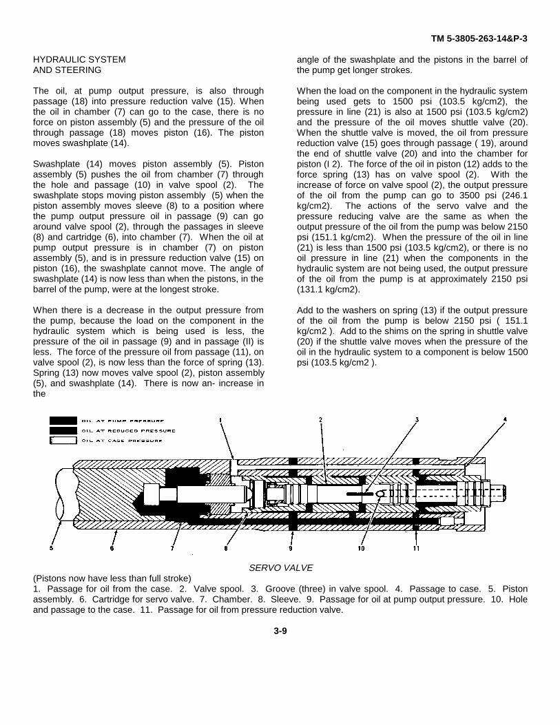
The oil, at pump output pressure, is also throughpassage (18) into pressure reduction valve (15). Whenthe oil in chamber (7) can go to the case, there is noforce on piston assembly (5) and the pressure of the oilthrough passage (18) moves piston (16). The pistonmoves swashplate (14).
Swashplate (14) moves piston assembly (5). Pistonassembly (5) pushes the oil from chamber (7) throughthe hole and passage (10) in valve spool (2). Theswashplate stops moving piston assembly (5) when thepiston assembly moves sleeve (8) to a position wherethe pump output pressure oil in passage (9) can goaround valve spool (2), through the passages in sleeve(8) and cartridge (6), into chamber (7). When the oil atpump output pressure is in chamber (7) on pistonassembly (5), and is in pressure reduction valve (15) onpiston (16), the swashplate cannot move. The angle ofswashplate (14) is now less than when the pistons, in thebarrel of the pump, were at the longest stroke.
When there is a decrease in the output pressure fromthe pump, because the load on the component in thehydraulic system which is being used is less, thepressure of the oil in passage (9) and in passage (II) isless. The force of the pressure oil from passage (11), onvalve spool (2), is now less than the force of spring (13).Spring (13) now moves valve spool (2), piston assembly(5), and swashplate (14). There is now an- increase inthe
angle of the swashplate and the pistons in the barrel ofthe pump get longer strokes.
When the load on the component in the hydraulic systembeing used gets to 1500 psi (103.5 kg/cm2), thepressure in line (21) is also at 1500 psi (103.5 kg/cm2)and the pressure of the oil moves shuttle valve (20).When the shuttle valve is moved, the oil from pressurereduction valve (15) goes through passage ( 19), aroundthe end of shuttle valve (20) and into the chamber forpiston (I 2). The force of the oil in piston (12) adds to theforce spring (13) has on valve spool (2). With theincrease of force on valve spool (2), the output pressureof the oil from the pump can go to 3500 psi (246.1kg/cm2). The actions of the servo valve and thepressure reducing valve are the same as when theoutput pressure of the oil from the pump was below 2150psi (151.1 kg/cm2). When the pressure of the oil in line(21) is less than 1500 psi (103.5 kg/cm2), or there is nooil pressure in line (21) when the components in thehydraulic system are not being used, the output pressureof the oil from the pump is at approximately 2150 psi(131.1 kg/cm2).
Add to the washers on spring (13) if the output pressureof the oil from the pump is below 2150 psi ( 151.1kg/cm2 ). Add to the shims on the spring in shuttle valve(20) if the shuttle valve moves when the pressure of theoil in the hydraulic system to a component is below 1500psi (103.5 kg/cm2 ).
SERVO VALVE(Pistons now have less than full stroke)1. Passage for oil from the case. 2. Valve spool. 3. Groove (three) in valve spool. 4. Passage to case. 5. Pistonassembly. 6. Cartridge for servo valve. 7. Chamber. 8. Sleeve. 9. Passage for oil at pump output pressure. 10. Holeand passage to the case. 11. Passage for oil from pressure reduction valve.
3-9

TM 5-3805-263-14&P-3COMBINATION VALVE
The oil from the variable displacement pump goesthrough the combination valve when the engine isrunning. The pump oil from the combination valve goesto the two control valves for the implements and to themetering valve for the steering.
VALVES IN THE COMBINATION VALVE1. Unloading valve. 2. Pressure reduction valve. 3.Relief valve. A relief valve for the oil circuits to the controlvalves for the implements (3), a valve that makes areduction in the pressure of the oil from the-pump to thesteering system (2), and an unloading valve (1), are partsof the combination valve.
UNLOADING VALVE(Part of combination valve)
1. Control lever UNLOAD position. 2. Line from pump.3. Opening to other part of combination valve. 4. Valvespool. 5. Line to tank. 6. Opening from other part ofcombination valve.
SYSTEMS OPERATION
The oil from the pump goes through line (2), aroundvalve spool (4) and through opening (3) to the other partof the combination valve and to the hydraulic system.
The pistons, in the variable displacement pump, are attheir longest stroke as the engine is started. Because ofthe closed hydraulic system and the pump at high outputgpm (litre/min), there is an added load on the starterbeing used to start the engine. When the outsidetemperature is low, the movement of the oil in thehydraulic system is slow and the pump would put moreload on the starter when it is starting the engine. Theunloading valve can remove most of the hydraulic loadwhen the engine is being started. When the control leveris held in UNLOAD position (1), valve spool (4) is movedto let the pump oil through line (2) go along the grooveon valve spool (4) and go through line (5) to the tank.
Relief Valve and Pressure Reduction ValveThe relief valve and the valve for the reduction of oil
pressure for the steering system are in the same valvehousing. The relief valve is in the circuit from the pump.The pressure reduction valve is in the same circuit as therelief valve. The pump oil, through the valve to thecontrols for the implements, can be as high as thesetting of the relief valve. The setting of the relief valveis approximately 3900 psi (274.2 kg/cm2). The oil,through pressure reduction valve to the steering system,has a setting of a approximately 1825 psi (128.3 kg/cm2)
8J7238 RELIEF VALVE AND VALVE FOR PRESSUREREDUCTION
1. Passage for oil from pump. 2. Line to control forimplements. 3. Line to control for implements. 4.Piston. S. Check valve. 6. Passage to tank. 7.Passage in piston. 8. Line to steering system. 9. Dumpvalve. 10. Washer and shims. 11. Spring for dumpvalve. 12. Pilot valve. 13. Spring. 14. Shims. 15.Springs (two, inner and outer).
3-10

TM 5-3805-263-14&P-3
HYDRAULIC SYSTEMAND STEERINGNOTE: The setting used in the pressure control valve forthe steering circuit is 1825 + 25 psi (128.3 + 1.8 kg/cm2).
9J4818 VALVE GROUPS1. Passage for oil from pump. 2. Line to control forimplements. 3. Line to control for implements. 4.Piston. 5. Check valve. 6. Passage to tank. 7.Passage in piston. 8. Line to steering system. 9. Dumpvalve. 10. Washers and shims. 11. Spring for dumpvalve. 12. Pilot valve. 13. Spring. 14. Shims. 15.Spring.
The pump oil in passage (1) goes through the orificein dump valve (9) and into the chamber for spring (11).The pressure of the oil, and spring (1I), keeps dumpvalve (9) closed. The oil in the spring chamber is againstpilot valve (12) which is held closed by spring (13). If thepressure of the oil gets to approximately 3900 psi (274.2kg/cm2), the oil in the chamber for spring (11) openspilot valve (12). This oil goes into passage (6). Withonly the force of spring (11) on dump valve (9), the pumpoil in passage (1) opens dump valve (9) and goes intopassage (6) to the tank. The relief valve prevents thepressure of the oil, between the pump
and the implements, from going higher than the settingof the relief valve.
The pump oil in passage ( ) goes around piston (4),through check valve (5) and through line (8) to themetering valve for the steering system. Piston (4) is heldin an open position by spring (15). The oil to check valve(5) also goes through passage (7), into a chamber inpiston (4). When the pressure of the oil in line (8) and inpiston (4) is approximately 1825 psi (128.3 kg’cm2), theforce of the oil is more than the force of springs (15), andthe piston moves to a position that stops the oil frompassage (1) to line (8). When the pressure of the oil inline (8) and the piston is less than 1825 psi (128.3kg’cm2), spring (15) moves the piston to let more oil goto line (8). When the pressure of the pump oil inpassage (I) is more than 1825 psi (128.3 kg,’cm2), theaction of springs (15) and the pressure of the oil in piston(4) keeps the pressure of the oil to the steering system at1825 psi (128.3 kg,’cm2).
The pressure setting of the relief valve can bechanged. Add to shims (14) for an increase. Removeshims for a decrease. Add to shims (10) for an increasein the regulation of the oil pressure to the steeringsystem. Remove shims for a decrease in pressure.
STEERING SYSTEMWhen the engine is running, the oil from the pump goesthrough relief and pressure reduction valve (6), throughline (7), to metering valve (2) for the steering. Thepressure of the oil in line (7) is approximately 1825 psi(128.3 kg,’cm2). The movement of the steering wheeloperates the metering valve. When the steering wheel isbeing turned in the direction of a right turn (clockwise),the oil from line (7) goes through metering valve (2) andthrough line (3). The oil in line (3) goes to the rod end ofcylinder (13), and to the head end of cylinder (14) andthe rods in the cylinders move. The cylinder rods movethe front wheels to positions that will let the machinemake a right turn. The oil from the head end of cylinder (13) and from the rod end of cylinder (14) goes throughline (4), through metering valve (2) and through line (I) tothe tank.
3-11

TM 5-3805-263-14&P-3
SYSTEMS OPERATION
HYDRAULIC SYSTEM FOR STEERING1. Line to tank. 2. Metering valve for steering. 3. Line to rod end of right cylinder and to head end of left cylinder. 4.Line to head end of right cylinder and rod end of left cylinder. 5. Passage for pump oil. 6. Combination valve (relief andpressure reduction valves). 7. Line for oil to the metering valve. 8 and 9. Relief valves (both in the same housing) for thesteering cylinders. 10. Passage for oil to tank. 11. Line to control valve for implements. 12. Line to control valve forimplements. 13. Steering cylinder on right side. 14. Steering cylinder on left side.
When the steering wheel is not being turned the oil inlines (3) and (4), and in cylinders (13) and (14), can notmove and the front wheels stay in position. If the side ofone of the front wheels hits a restriction (material that willnot move), the positions of the front wheels twill move.The force on the side of the wheel causes an increase inthe pressure of the oil in the cylinders and in one of thelines to the cylinders. When the pressure of the oil in theline gets to 1700 psi (119.5 kg’cm2), relief valve (8) or (9)opens. The high pressure oil in the line goes through theopen relief valve and into the other line to the cylinders.This lets the positions of the front wheels change.
The pressure setting of relief valves (8) and (9) canbe changed. For an increase in the pressure setting,add shims in the plug over the spring in the valve.Remove shims for a decrease in the pressure setting.
FRONT OF MOTOR GRADER8 and 9. Plugs for relief valve. 13. Steering cylinder onright side.
3-12

TM 5-3805-263-14&P-3HYDRAULIC SYSTEMAND STEERING
Metering Valve for Steering
METERING VALVE FOR STEERING1. Shaft. 2. Spool. 3. Sleeve. 4. Outlet (to tank). 5. Inlet (for pump oil). 6. Pump gear. 7. Pump gear (internal). 8. Flatsprings. 9. Pin. 10. Opening to steering cylinders (left). 11. 0pening to steering cylinders (right). 12. Body. 13. Drove.
When the engine is running, the pump keeps thepressure of the oil in inlet (5) at approximately 1825 psi(128.3 kg cm2). The pump oil does not go through themetering Nvalve until the steering wheel is turned.
The steering wheel is installed on shaft (1). When thesteering wheel is turned clockwise to make a right turn,shaft (1) turns spool (2). After the spool turns a fewdegrees, flat springs (8), in the spool, turn sleeve (3).The spool and the sleeve turn, but they turn a fewdegrees from being together. The pin (9), in spool (2),turns drive (13) which turns pump gear (6) in pump gear(7). Pump gear (7) does not turn.
When spool (2) moves before sleeve (3) is moved, theholes in the sleeve get in line with grooves in the spool.The pump oil in inlet (5) goes through the holes in thesleeve into the grooves in the spool. The oil in thegrooves goes through other holes in the sleeve andthrough a passage in body (12). The oil from thepassage in the bode goes into pump gears (6) and (7).
As pump gear (6) is turned by drive (1 3), the oil ismoved to another passage in body (1 2), through moreholes in the sleeve and other grooves in the spool, andthrough opening (11) to the steering
cylinders. The oil from the cylinders goes throughopening (10), passages in body ( 1 2), holes in sleeve(3), grooves in spool (2) and through passages to outlet(4). The oil from outlet (4) goes to the tank.
PUMP GEARS IN METERING VALVE6. Pump gear. 7. Pump gear (internal). 9. Pin. 13.
Drive.When turning the steering wheel is stopped, most of
the parts connected to shaft (I) also stop. Flat springs (8)now move the sleeve a few degrees in the samedirection that it was being turned. Now the holes in thesleeve do not line up with the grooves in the spool andthe flow of oil stops in inlet (5) of the metering valve.When the steering wheel is not being turned, the oilcannot get in or get out of the steering cylinders whichkeeps the wheels positioned for a right turn.
3-13