tm 3-4240-346-10 m40a1 + m42a2 mask august 2010
DESCRIPTION
US Army Operator's Manual For The M40A1 Gas MaskTRANSCRIPT

*TM 3-4240-346-10 TM 09204A/09205A-10/1
OPERATOR’S MANUAL FOR
CHEMICAL-BIOLOGICAL MASK: FIELD, M40A1 (4240-01-370-3821 – SMALL)
(4240-01-370-3822 – MEDIUM) (4240-01-370-3823 – LARGE)
CHEMICAL-BIOLOGICAL MASK: COMBAT VEHICLE, M42A2 (4240-01-413-4100 – SMALL)
(4240-01-413-4101 – MEDIUM) (4240-01-413-4102 – LARGE)
*This TM supersedes TM 3-4240-346-10/TM 09204A/09205A-10/1 dated 1 August 1998 SEE BACK COVER FOR WARNING, DISTRIBUTION STATEMENT, AND DESTRUCTION NOTICE
HEADQUARTERS DEPARTMENT OF THE ARMY AND, HEADQUARTERS, MARINE CORPS
31 AUGUST 2010 PCN 184 092040 00


a
WARNING
WARNINGs point out dangerous steps in the procedures in this manual. Your safety depends on following the instructions included in all WARNINGs. Several general WARNINGs are included below: • It is important to properly clean your mask. A dirty mask will compromise its ability to provide maximum protection. • If you have not used your mask for 30 days or more, perform all PMCS prior to using your mask. • You must check your mask assembly for leaks when fitted and each time mask assembly is put on. A leaky mask assembly will not protect you from toxic agents. • Perform the steps for putting on your mask quickly. You must put the facepiece assembly on before you take another breath. DO NOT wear contact lenses. Contact lenses will over correct vision while wearing optical inserts. DO NOT change canister in a contaminated area. • DO NOT wear contact lenses with your mask assembly. • DO NOT wear contact lenses (soft or hard) while wearing CB protective masks. Inadequate oxygen supply to the corneal surface, exposure to dust, dirt, and smoke/gas may cause serious vision loss or eye damage. Warfighters requiring vision correction are provided optical inserts for their protective masks. • DO NOT use the mask assembly if outlet valve disk or outlet valve cover is missing or damaged. The mask assembly will leak.

b
WARNING (CONT.)
• DO NOT use mask assembly if inlet valve body or inlet valve disk are missing. The mask assembly will leak. • DO NOT use tissue paper or a paper towel to remove dirt or moisture from outlet valve cover, outlet valve disk, or outlet valve seat. Paper may break up and lodge in outlet valve area, causing leakage. • DO NOT connect the drink tube to your canteen until all mating surfaces have been checked and are free of contamination. Chemical agents could be swallowed, resulting in sickness or death. • Fill your plastic water canteen before entering contaminated area, or, if in a contaminated area, fill canteen inside a protective shelter. • If resistance is not felt, drinking system is leaking. DO NOT drink. Replace canteen. If resistance is still not felt, notify CBRN NCO for maintenance. • If resistance is not felt, drinking system is leaking. Notify CBRN NCO to repair or replace mask. • To prevent possible leakage around mask assembly, DO NOT pull on external drink tube when removing canteen. • Care should be taken not to break the mask assembly seal while pressing in on the outlet valve cover. • When putting on your helmet, be sure not to break the seal between your mask and the side of your face. Toxic agents could leak into your mask. • The waterproof bag is to be used for waterborne operations only.

c
• In cold weather, DO NOT clear mask by exhaling a large volume of air. Moist air will frost eyelenses and impair vision. • If you become overheated in extremely cold weather, do not remove your mask outdoors until your face and head have cooled and any sweat has dried. Frostbite may result if mask is removed while your face is still wet. • Any solid matter under outlet valve disk will cause leakage. • DO NOT allow dirt or foreign material to remain in carrier. Dirt or foreign material in carrier may get into valves, causing them to leak. • Make sure the gasket is present in the hose fitting before connecting the canister to the hose. A missing gasket will affect the seal and will allow the wearer to inhale contaminated air. • Star knob must be tight or movement of the hose may cause it to loosen and leak.

d
WARNING (CONT.)
HEALTH/ENVIRONMENTAL HAZARD. There are two Mask Canisters, the C2 and the C2A1. • The C2 canister contains Chromium VI, and damaged or unusable canisters are considered Hazardous Waste. (Chromium VI is a known carcinogen if inhaled or swallowed.) • The C2A1 canister is chromium-free but must continue to be disposed of in accordance with State and Local Environmental Laws. • DO NOT throw away damaged or unusable canisters as ordinary trash. • DO turn in damaged or unusable canisters to your hazardous waste management office or Defense Reutilization and Marketing Office (DRMO).
FIRST AID. For first aid, refer to FM 4-25.11.

TECHNICAL MANUAL DEPARTMENT OF THE ARMY NO. 3-4240-346-10 AND HEADQUARTERS MARINE CORPS NO. 09204A/09205A-10/1 WASHINGTON, D.C., 31 AUGUST 2010
OPERATOR’S MANUAL FOR
CHEMICAL-BIOLOGICAL MASK: FIELD, M40A1 (4240-01-370-3821 - SMALL)
(4240-01-370-3822 - MEDIUM) (4240-01-370-3823 - LARGE)
CHEMICAL-BIOLOGICAL MASK: COMBAT VEHICLE, M42A2 (4240-01-413-4100 - SMALL)
(4240-01-413-4101 - MEDIUM) (4240-01-413-4102 - LARGE)

REPORTING ERRORS AND RECOMMENDING IMPROVEMENTSYou can help improve this manual. If you find any mistakes or if you know of a way to improve the procedures, please let us know. Reports, as applicable by the requiring Service, should be submitted as follows: Mail your letter or DA Form 2028 (Recommended Changes to Publications and Blank Forms) directly to: US Army Research, Development, and Engineering Command, ATTN: RDCB-DEL, 5183 Blackhawk Road, Aberdeen Proving Ground, MD 21010-5424. You many also send in your recommended changes via e-mail to [email protected]. A reply will be furnished directly to you.

iii
TABLE OF CONTENTS WORK PACKAGE
CHAPTER 1. General Information, Equipment Description and Data, and Theory of Operation General Information ............................................................................................... 0001 Equipment Description and Data ........................................................................... 0002 Theory of Operation ............................................................................................... 0003
CHAPTER 2. Operator Instructions Description and Use of Operator Controls and Indicators ..................................... 0004 Operation Under Usual Conditions ........................................................................ 0005 Operation Under Unusual Conditions .................................................................... 0006
CHAPTER 3. Troubleshooting Procedures Troubleshooting Procedures..................................................................................0007
CHAPTER 4. Operator Maintenance Instructions Operator Preventive Maintenance Checks and Services (PMCS) ........................ 0008 Operator Maintenance Procedures........................................................................ 0009

iv
TABLE OF CONTENTS (CONT) WORK PACKAGE
CHAPTER 5. Supporting Information References............................................................................................................. 0010 Components of End Item and Basic Issue Items List ............................................ 0011 Additional Authorized Items List............................................................................. 0012 Expendable and Durable Items List ....................................................................... 0013

v
HOW TO USE THIS MANUAL The safest, easiest, and best way to use these CB Masks (M40A1/M42A2) is to follow the instructions in this manual. Knowing what is in this manual and how to use it will save you time and work, and will help you save your life when fighting in a Chemical, Biological, Radiological, Nuclear (CBRN) environment.
ORGANIZATION The table of contents on page iii provides easy access to the manual. Pages are numbered consecutively within each chapter; each page number is prefixed with the Work Package (WP) number. For example, page 2 of WP 0004 is numbered 0004-2. This manual is divided into five chapters. Chapter 1 contains general information, equipment description, and theory of operation. Chapter 2 provides operating instructions for the M40A1 and the M42A2 masks, including operation of the mask under usual conditions and unusual conditions. Chapter 3 provides a malfunction index and troubleshooting procedures. Chapter 4 provides instructions for operator maintenance procedures, including preventive maintenance checks and services (PMCS). Chapter 5 contains supporting information, such as the Additional Authorization List and identifies supplies used in maintaining these masks. Each section of the manual is further divided into three parts. The first addresses common procedures that are the same regardless of which mask you are using. The second addresses those tasks that are peculiar to the M40A1 and the third addresses those peculiar to the M42A2. Therefore, depending on which mask you are using, you must follow the instructions in the common procedures and the procedures that are peculiar to your mask.

vi
ORGANIZATION (CONT) For instance, if you have the M40A1 mask, you must do the Before PMCS checks under COMMON and those under the M40A1 PECULIAR. Those tasks listed under the M42A2 are not required. Those tasks which are considered to be COMMON and apply to either mask are illustrated using the M40A1. However, the differences between the M40A1 and the M42A2 do not impact on the task, and, in many cases, you will not be able to tell from the illustration which mask is being illustrated.
HOW TO FIND PROCEDURES If you are using the manual to perform Troubleshooting, go to (WP 0007) and read the instructions there. If you are going to do operator level scheduled maintenance, you can turn directly to Preventive Maintenance Checks and Services (PMCS), (WP 0008), and proceed according to the instructions there. The PMCS table provides procedures for checks and services to be performed before (WP 0008-5 for M40A1/M42A2) (WP 0008-10 for M42A2 only), during (WP 0008-11 for M40A1/M42A2) (WP 0008-12 for M42A2 only), and after (WP 0008-13 for M40A1/M42A2) (WP 0008-33 for M42A2 only) using the mask. If you are performing a task under usual conditions, go to the table of contents and find the first page of that section. There is a secondary table of contents on the first page of that section. It will tell you the page in WP 0005 where your task begins. For example, if you wish to don your mask, proceed to WP 0005-1. On the first page of this work package you will find a table of contents that will tell you on which page the task begins. Turn to the page and follow the instructions to put on and use your mask under usual conditions.

0001 - 1
CHAPTER 1. GENERAL INFORMATION, EQUIPMENT DESCRIPTION AND DATA, AND THEORY OF OPERATION GENERAL INFORMATION 0001SCOPE Type of Manual. Operators Manual. Model Numbers and Equipment Name. Chemical-Biological Mask: Field M40A1 and Chemical-Biological Mask: Combat Vehicle M42A2. Purpose of Equipment. Protects the face, eyes, and lungs from field concentrations of CB agents, toxins, and radioactive fallout particles. Special Limitations on Equipment. Does not protect against ammonia or carbon monoxide gases. Does not protect you in closed spaces where there is not enough oxygen in the air. MAINTENANCE FORMS AND RECORDS (A) Department of the Army forms and procedures used for equipment maintenance will be those prescribed by DA PAM 750-8, The Army Maintenance Management System (TAMMS) Users Manual; DA PAM 738-751, Functional Users Manual for the Army Maintenance Management Systems – Aviation (TAMMS-A); or AR 700-138, Army Logistics Readiness and Sustainability. (MC) Maintenance forms and records used by Marine Corps personnel are prescribed by TM 4700-15/1.

0001 - 2
REPORTING EQUIPMENT IMPROVEMENT RECOMMENDATIONS (EIR) If your mask needs improvement, let us know. Send us an EIR. You, the user, are the only one who can tell us what you don't like about your equipment. Let us know why you don't like the design or performance. If you have Internet access, the easiest and fastest way to report problems or suggestions is to go to https://aeps.ria.army.mil/aepspublic.cfm (scroll down and choose the “Submit Quality Deficiency Report” bar). The Internet form lets you choose to submit an Equipment Improvement Recommendation (EIR), a Product Quality Deficiency Report (PQDR) or a Warranty Claim Action (WCA). You may also submit your information using an SF 368 (Product Quality Deficiency Report). You can send your SF 368 via e-mail, regular mail, or facsimile using the addresses/facsimile numbers specified in DA PAM 750-8, The Army Maintenance Management System (TAMMS) Users Manual. We will send you a reply. For Marine Corps users: Quality Deficiency Reports (QDR) shall be submitted on SF 368 in accordance with MCO 4855.10. A reply will be furnished to you.

0001 - 3
CHEMICAL, BIOLOGICAL, RADIOLOGICAL, AND NUCLEAR INFORMATION RESOURCE CENTER (CBRN-IRC) EQUIPMENT HOTLINE Do you have a problem or question about the equipment covered in this publication and need to talk to someone? There is a hotline at the CBRN-IRC that you can contact. The phone numbers are toll free from the USA and these lines are manned during our normal duty hours. If you call during our off duty hours, you can leave a voice mail message and we will get back to you. Your e-mail or facsimile (FAX) message can be sent at any time and will be handled during the next business day. The numbers are: Toll Free: 1-800-831-4408 DSN: 793-7349 Commercial: 309-782-7349 FAX (DSN): 793-1919 FAX (Commercial): 309-782-1919 E-mail: [email protected] CORROSION PREVENTION AND CONTROL (CPC) Corrosion Prevention and Control (CPC) of Army materiel is a continuing concern. It is important that any corrosion problems with this item be reported so that the problem can be corrected and improvements can be made to prevent the problem in future items.

0001 - 4
CORROSION PREVENTION AND CONTROL (CPC) (CONT) While corrosion is typically associated with rusting of metals, it can also include deterioration of other materials such as rubber and plastic. Unusual cracking, softening, swelling, or breaking of these materials may be a corrosion problem. If a corrosion problem is identified, it can be reported using a Quality Deficiency Report, SF 368. Use of key words such as “corrosion”, “rust”, “deterioration”, or “cracking” will assure that the information is identified as a CPC problem. The form should be submitted to address specified in DA PAM 750-8, The Army Maintenance Management System (TAMMS). Marine Corps Units report CPC problems using SF 368 , in accordance with MCO 4855.10. DESTRUCTION OF ARMY MATERIEL TO PREVENT ENEMY USE Refer to TM 43-0002-31 for methods of destruction. PREPARATION FOR STORAGE OR SHIPMENT Refer to TM 3-4240-346-23&P for preparation for storage or shipment.

0001 - 5
LIST OF ABBREVIATIONS AND ACRONYMS AQD Armor Quick Disconnect CB Chemical Biological CBRN-IRC Chemical Biological Radiological Nuclear Information Resource Center CBRN NCO Chemical Biological Radiological Nuclear Noncommissioned Officer CPC Corrosion Prevention and Control DA Department of the Army EIR Equipment Improvement Recommendation JSLIST Joint Service Lightweight Integrated Suit Technology M40A1 Chemical-Biological Mask: Field M42A2 Chemical-Biological Mask: Combat Vehicle PQDR Product Quality Deficiency Report QDC Quick Disconnect Coupling QDH Quick Doff Hood QDR Quality Deficiency Report TAMMS The Army Maintenance Management System TM Technical Manual WCA Warranty Claim Action

END OF WORK PACKAGE
0001 - 6
Figure 1. Chemical-Biological Mask: Field, M40A1.
Figure 2. Chemical-Biological Mask: Combat Vehicle, M42A2.

0002 - 1
EQUIPMENT DESCRIPTION AND DATA 0002
EQUIPMENT CHARACTERISTICS, CAPABILITIES, AND FEATURES COMMON The lightweight, Chemical Biological (CB) masks (M40A1 / M42A2) are easy to prepare for transport and storage. The mask assembly is kept dry, when required by climate and mission, by a waterproof bag and stored in a carrier made of mildew-resistant, water repellent fabric. The facepiece is made of silicone rubber with an inturned sealing surface so it can provide protection to face, eyes, and respiratory tract from CB agents, toxins and radioactive particles. The mask assembly is not intended for use in an oxygen deficient environment. Neither is it intended to provide protection against carbon monoxide or ammonia. It forms a comfortable seal on a Warfighter’s face as it protects against adverse elements. The mask assembly is equipped with both front and side voicemitters for ease of communication and an outlet valve body with a drinking system. To ensure a comfortable fit, the mask assembly is issued in three sizes: small, medium and large which are marked with S, M and L on the forehead. It is also equipped with clear and neutral gray outserts to protect the eyelens from scratches, reduce sun glare and prevent fogging in cold weather. The masks have a second skin or universal second skin, which fits to the facepiece and protects the facepiece from liquid agents, and a quick doff hood (if applicable) made of lightweight, butyl rubber-coated fabric, which provides protection to the head and neck from liquid toxic chemical agents. The second skin or universal second skin is issued in two sizes: small and medium/large which are marked S and M/L on the exterior left cheek.

0002 - 2
EQUIPMENT CHARACTERISTICS, CAPABILITIES, AND FEATURES (CONT) M42A2 PECULIAR The CB mask, M42A2, features a canister carrier, hose assembly, and combat vehicle carrier. The M42A2 masks have a microphone communication capability that can couple with on board communication systems, through the Combat Vehicle Communications (CVC) helmet.
LOCATION AND DESCRIPTION OF MAJOR COMPONENTS GENERAL Make sure you are familiar with the location and operation of all mask parts and additionally authorized items before attempting to use the mask. COMMON
FACEPIECE ASSEMBLY • FACEPIECE (1) Fits closely against the face to form a seal. It is made of silicone rubber. • HEAD HARNESS (2) Consists of a headpad, forehead straps, temple straps, cheek straps, and
donning tab. Secures facepiece assembly to the face. • NOSECUP ASSEMBLY (3) Made of soft rubber; fits over the nose and mouth. • NOSECUP VALVE SEATS (4) Hard plastic ring that holds the silicone rubber NOSECUP
VALVE DISKS (5) on the inside of the nosecup. • INTERNAL DRINK TUBE (6) Rubber tube located inside the nosecup.

0002 - 3
• AIRFLOW DEFLECTOR (7) Hard plastic piece located inside the facepiece assembly. Supports the inlet valve body and inlet valve disk. Directs air across eyelenses to reduce fogging.
• INLET VALVE BODY (8) Round rubber piece located on the outside of the facepiece that connects to the airflow deflector.
• INLET VALVE DISK (9) Thin silicone disk located between the inlet valve body and the airflow deflector.
• OUTLET VALVE COVER (10) Rubber cover surrounding the OUTLET VALVE BODY (11). • RETAINER (12) Cavity on the side of the outlet valve cover. Used for storage of QUICK
DISCONNECT COUPLING (QDC) (13). • OUTLET VALVE DISK (14) Silicone rubber disk that fits into the outlet valve body. • FRONT AND SIDE VOICEMITTERS (15) Round, indented metal pieces on the front and side of
the facepiece. • EXTERNAL DRINK TUBE (16) Consists of a length of tubing and a QDC. • RETAINING CLAMP (17) Clamps around the outlet valve body. • RETAINING RING (18) secures the side voicemitter to the facepiece.

LOCATION AND DESCRIPTION OF MAJOR COMPONENTS, COMMON (CONT) FACEPIECE ASSEMBLY (CONT)
2 1
8
9
7
4
0002 - 4
6
16
10
14
17
15
5
3
18
11
13 12

CANISTER • CANISTER (19) Filters out CB agents and other particles
from contaminated air. 19
0002 - 5
SECOND SKIN
NOTE Compatible with JSLIST (TM 10-8415-220-10) and quick doff hood. Not
compatible with Saratoga.
• The SECOND SKIN (20) is made of butyl rubber and covers the facepiece assembly. • RUBBER CATCHES (21) are located at the top and bottom of the second skin. • RIDGE (22) a groove around the outside edge of the second skin.
21
20
22
LOCATION AND DESCRIPTION OF MAJOR COMPONENTS, COMMON (CONT) UNIVERSAL SECOND SKIN
NOTE Compatible with JSLIST (TM 10-8415-220-10), Saratoga (TM 10-8415-209-10/ TM8415-10), and quick doff hood.
0002 - 6
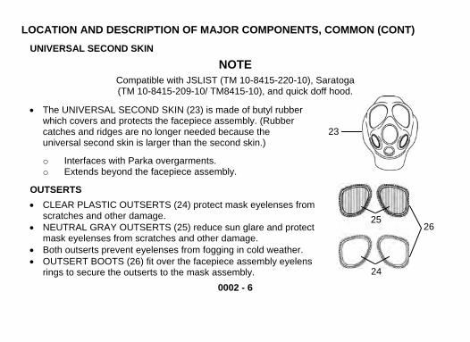
• The UNIVERSAL SECOND SKIN (23) is made of butyl rubber which covers and protects the facepiece assembly. (Rubber catches and ridges are no longer needed because the universal second skin is larger than the second skin.)
23
o Interfaces with Parka overgarments. o Extends beyond the facepiece assembly.
OUTSERTS • CLEAR PLASTIC OUTSERTS (24) protect mask eyelenses from
scratches and other damage. 25
24
26• NEUTRAL GRAY OUTSERTS (25) reduce sun glare and protect mask eyelenses from scratches and other damage.
• Both outserts prevent eyelenses from fogging in cold weather. • OUTSERT BOOTS (26) fit over the facepiece assembly eyelens
rings to secure the outserts to the mask assembly.

M1 WATERPROOF BAG
WARNING The waterproof bag is to be used for waterborne operations only.
CAUTION Remove mask assembly from waterproof bag as soon as protection of mask is no longer required.
• M1 WATERPROOF BAG (27). The folded waterproof bag and a small envelope containing the RUBBER BANDS (28), for sealing, are packed in the carrier. Instructions for use are printed on the waterproof bag.
27
28
0002 - 7

LOCATION AND DESCRIPTION OF MAJOR COMPONENTS (CONT) M40A1 PECULIAR
FIELD MASK CARRIER
NOTE DO NOT make any markings on the mask carrier. The ID pocket will be used for required unit information.
• The FIELD MASK CARRIER (29) is designed to serve the field mask only. It is made of mildew-resistant, water-repellant fabric. It has adjustable straps. It is closed with a flap held by hook and pile material. It includes:
0002 - 8
• SHOULDER STRAP (30) • WAIST STRAP (31) • SHORT STRAP (32) • SHORT ADJUSTABLE STRAP (33) • ID POCKET (34). See TM 3-4240-346-23&P,
WP 0035 for Mask System Identification. • QUICK-OPENING FLAP (35) with hook and pile
fastener, provides for ready access to contents.
34
33
32
31
30
29
35

M42A2 PECULIAR
DETACHABLE MICROPHONE
0002 - 9
• DETACHABLE MICROPHONE (36) connects into front voicemitter of the protective mask, its cord plugs into the CVC helmet and enables radio communication in the combat vehicle.
36
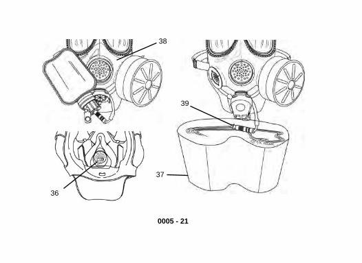
QUICK DOFF HOOD
37 38
39
• QUICK DOFF HOOD (QDH) (37) is made of butyl rubber-coated fabric, which protects the part of the neck and head that is not covered by mask assembly against CB agents, toxins, and radioactive fallout particles.
• ELASTIC AROUND OPENING (38) secures QDH around the second skin. It enables easy removal of the QDH during decon operations.
• UNDERARM STRAPS (39) retain the QDH on the shoulders. PLASTIC FASTENERS (40) are used to secure the straps.
40

LOCATION AND DESCRIPTION OF MAJOR COMPONENTS, M42A2 PECULIAR (CONT)
CANISTER CARRIER • CANISTER CARRIER (41) interfaces with the C2/C2A1
canisters and a variety of North Atlantic Treaty Organization (NATO) canisters.
41
0002 - 10
45
44
42
43 • ARMOR QUICK DISCONNECT (AQD) (42)
attaches to the CANISTER COVER (43) and permits the canister to be coupled to a vehicle’s Gas Particulate Filter Unit (GPFU).
HOSE ASSEMBLY • STAR KNOB (44) permits easy attachment
of the hose assembly to the facepiece assembly. It may be switched from left to right by unit CBRN NCO.
• HOSE ASSEMBLY (45) Connects the canister and canister carrier to the facepiece assembly.

COMBAT VEHICLE CARRIER
NOTE DO NOT make any markings on the mask carrier. The ID pocket will be used for required unit information.
• The COMBAT VEHICLE CARRIER (46) is designed to serve the combat vehicle mask. It is made of mildew-resistant, water-repellant fabric. It has adjustable straps. It is closed with a flap held by hook and pile material. It includes:
• SHOULDER STRAP (47)
0002 - 11
• WAIST STRAP (48) • ID POCKET (49) • AQD POCKET (50) to cover the AQD. • QUICK-OPENING FLAP (51), with hook
and pile fastener, provides for ready access to contents.
• SHORT STRAP (52) • SHORT ADJUSTABLE STRAP (53)
52 46
5053
48
51
49
47

DESCRIPTION OF ADDITIONAL AUTHORIZED ITEMS LIST OPTICAL INSERTS
WARNING DO NOT wear contact lenses with your mask assembly.
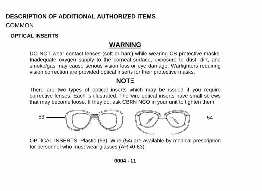
NOTE There are two types of optical inserts which may be issued if you require corrective lenses. Each is illustrated. The wire optical inserts have small screws that may become loose. If they do, ask CBRN NCO in your unit to tighten them.
0002 - 12
54 55
• OPTICAL INSERT Plastic (54), Wire (55) are available by medical prescription for personnel who must wear glasses (AR 40-63).

0002 - 13
CANTEEN WITH M1 CANTEEN CAP • CANTEEN includes the M1 CANTEEN CAP which is a special cap that allows drinking system to
be connected to the canteen.
M8 CHEMICAL AGENT DETECTOR PAPER • M8 CHEMICAL AGENT DETECTOR PAPER consists of a book of perforated sheets of
chemically treated, dye-impregnated paper. A color comparison bar-chart is printed inside the front cover.
• Chemicals in paper cause specific color changes when paper contacts liquid nerve or blister agents.
• Instructions for use are on the cover of the book containing the detector paper.
M295 DECONTAMINATING PACKET, INDIVIDUAL EQUIPMENT • M295 DECONTAMINATING PACKET is used primarily for individual equipment. • Instructions for use are printed on the container and packets.
M291 DECONTAMINATING KIT • M291 DECONTAMINATING KIT is used primarily for skin. • Instructions for use are printed on the container and packets. • Refer to TM 3-4230-229-10.

• The M1 Laser Ballistic Outserts provide two wavelengths of laser protection and protection from low-speed fragments.
• The M7 AUDIO FREQUENCY AMPLIFIER is used in high noise areas and/or dismounted conditions to amplify your voice.
56
DESCRIPTION OF ADDITIONAL AUTHORIZED ITEMS LIST (CONT)
• AIRCREW DETACHABLE MICROPHONE (56) connects into front voicemitter of the protective mask. Its cord plugs into the aircraft internal communication system and enables radio communication.
0002 - 14
AIRCREW DETACHABLE MICROPHONE
M7 AUDIO FREQUENCY AMPLIFIER
M1 LASER BALLISTIC OUTSERTS

0002 - 15 / 16 BLANK
EQUIPMENT DATA TABULATED DATA
M40A1 Weight (with carrier) M40A1 mask: 4 lb. (1.81 kg) Dimensions (with carrier): 10.5 X 9 X 4 in. (26.67 X 22.86 X 10.16 cm.)
M42A2 Weight (with carrier) M42A2 mask: 5.23 lb. (2.37 kg) Dimensions (with carrier): 12 X 12.5 X 4 in. (30.48 X 31.75 X 10.16 cm.)
END OF WORK PACKAGE


THEORY OF OPERATION 0003M40A1 THEORY OF OPERATION Air enters the CANISTER (1), which is screwed into the side of the mask. The canister filters out Chemical Biological (CB) agents, toxins, and radioactive fallout particles from contaminated air. Filtered air then passes over the AIRFLOW DEFLECTOR (2) which is located inside the facepiece and on the same side as the canister. The air then moves into the eye area of the facepiece.
From the eye area, filtered air enters the NOSECUP (3) through NOSECUP VALVES (4). Filtered air from the nosecup is inhaled by the Warfighter. Exhaled air is passed through the nosecup area and out through the OUTLET VALVE DISK (5). The OUTLET VALVE COVER (6) protects the outlet valve body from contamination and damage, and enhances protection by surrounding the outlet valve disk with clean air. Provides a retainer for the external drink tube and QDC.
0003 - 1
2
3
4
56
1

END OF WORK PACKAGE
From the eye area, filtered air enters the NOSECUP (10) through NOSECUP VALVES (11). Filtered air from the nosecup is inhaled by the Warfighter. Exhaled air is passed through the nosecup area and out through the OUTLET VALVE DISK (12). The OUTLET VALVE COVER (13) protects the outlet valve body from contamination and damage, and enhances protection by surrounding the outlet valve disk with clean air. Provides a retainer for the external drink tube and QDC.
Air enters the canister, which is held in the CANISTER CARRIER (7). The canister filters out CB agents, toxins, and radioactive fallout particles from contaminated air. Filtered air then passes through the HOSE (8) and AIRFLOW DEFLECTOR (9), which is located inside the mask assembly and on the same side as the hose assembly. The air then moves into the eye area of the mask assembly.
7 8
0003 - 2
12
13
M42A2 THEORY OF OPERATION
10
11
9

CHAPTER 2. OPERATOR INSTRUCTIONS DESCRIPTION AND USE OF OPERATOR CONTROLS AND INDICATORS 0004
GENERAL 2Make sure you are familiar with the location and operation of all mask parts and additional authorized items before attempting to use the mask. 1
DESCRIPTION OF MASK COMMON
FACEPIECE ASSEMBLY • FACEPIECE (1). The facepiece fits closely against the face to form a seal.
The following components are molded/assembled into the silicone rubber facepiece: buckle tabs, eyelens, nosecup, voicemitters, outlet valve body, and canister/hose connectors.
• HEAD HARNESS (2). Constructed of elastic webbing sewn to a rectangular head pad and buckled to the facepiece. The ends of the head harness straps have metal strap end clips to prevent fraying of the elastic webbing. Ends of the head harness straps pass through buckles at the two forehead, temple and cheek positions. Elastic webbing connects the two forehead straps and holds them in proper alignment when the facepiece assembly is worn. Head harness straps attached to buckles at the ends of the tabs permit adjustment to obtain proper fit of the mask assembly.
0004 - 1

DESCRIPTION OF MASK, COMMON (CONT)
14
15
18
12
11 10
17 16
13
34
6
5
8 9
7
• NOSECUP ASSEMBLY (3). Made of soft rubber; fits over the Warfighter’s nose and mouth.
Diverts exhaled air toward the outlet valve to reduce fogging of the eye lens. • NOSECUP VALVE SEATS (4). Each of two nosecup valve seats holds a silicone rubber
NOSECUP VALVE DISK (5), which allows filtered air to enter nosecup and prevents moist exhaled air from fogging the eyelens in cold weather.
• INTERNAL DRINK TUBE (6). Allows the Warfighter to drink while wearing the mask assembly.
0004 - 2

0004 - 3
• AIRFLOW DEFLECTOR (7). Located inside the mask assembly, directs inhaled air over eye lens to reduce fogging. The airflow deflector also supports the inlet valve disk and the inlet valve body.
• INLET VALVE BODY (8) and INLET VALVE DISK (9). Fits onto airflow deflector, allows filtered air to enter the mask assembly and prevent moist exhaled air from entering the filter canister.
• OUTLET VALVE COVER (10). Protects outlet valve disk and outlet valve body from damage. • RETAINER (11). Holds external drink tube quick disconnect coupling. • OUTLET VALVE DISK (12) and OUTLET VALVE BODY (13). Located behind outlet valve cover;
releases exhaled air and closes on inhalation to prevent contaminated air from entering mask assembly.
• FRONT (14) AND SIDE VOICEMITTERS (15). Transmits the Warfighter’s voice outside the mask assembly.
• EXTERNAL DRINK TUBE (16). The external drink tube is used to connect the mask assembly to the M1 Canteen cap for drinking. It consists of a length of tubing and a QUICK DISCONNECT COUPLING (QDC) (17) that fits into the external drink tube retainer.
• RETAINING CLAMP (18). Clamps around outlet valve body to help prevent disbonding.

DESCRIPTION OF MASK, COMMON (CONT) CANISTER • CANISTER (19). Filters out CB agents and other particles
from contaminated air. 19
0004 - 4
SECOND SKIN (M40A1/M42A2)
NOTE Compatible with JSLIST (TM 10-8415-220-10) and quick doff hood. Not compatible with Saratoga.
• SECOND SKIN (20). The second skin is made of butyl rubber, and covers the facepiece assembly. It provides additional protection against liquid agents.
• RUBBER CATCHES (21). Used to retain the quick doff hood on the mask assembly. They are located at the top and bottom of the second skin.
• RIDGE (22) is used to retain the quick doff hood. 21
20
22
21

UNIVERSAL SECOND SKIN
NOTE Compatible with JSLIST, Saratoga (TM 10-8415-209-10), and quick doff hood.
• UNIVERSAL SECOND SKIN (23). Is made of butyl rubber and covers the facepiece assembly. It provides additional protection against liquid agents. (Rubber catches and ridges are no longer needed because the universal second skin is now larger.) 23
o Interfaces with Parka overgarments. o Extends beyond the facepiece assembly.
OUTSERTS • CLEAR PLASTIC OUTSERTS (24) protect mask eyelenses from scratches and other damage.
26
• NEUTRAL GRAY OUTSERTS (25) reduce sun glare and protect mask eyelenses from scratches and other damage.
• Both outserts prevent eyelenses from fogging in cold weather.
0004 - 5
24 25• OUTSERT BOOT (26) fits over the mask assembly eyelens rings to secure the outserts to the mask assembly.

DESCRIPTION OF MASK, COMMON (CONT) WATERPROOF BAG 27• M1 WATERPROOF BAG (27). The folded waterproof bag and a
small envelope containing the RUBBER BANDS (28) for sealing are packed in the carrier. The waterproof bag keeps the mask dry when required by climate and mission. Instructions for use are printed on the waterproof bag.
28
M40A1 PECULIAR
FIELD MASK CARRIER
NOTE DO NOT make any markings on the mask carrier. The ID pocket will be used for required unit information.
• FIELD MASK CARRIER (29) is designed to serve the field mask only. Mask carrier is made of mildew-resistant, water-repellant fabric. It has adjustable straps. It is closed with a flap held by hook and pile material.
0004 - 6

• SHOULDER STRAP (30)
0004 - 7
• WAIST STRAP (31) • SHORT STRAP (32) • SHORT ADJUSTABLE STRAP (33) • ID POCKET (34)
29
30
32
3133
34
35
M42A2 PECULIAR
DETACHABLE MICROPHONE • DETACHABLE MICROPHONE (35). Connects into front
voicemitter of the protective mask, its cord plugs into the CVC helmet and enables radio communication in the combat vehicle.

DESCRIPTION OF MASK, M42A2 PECULIAR (CONT) CANISTER CARRIER
0004 - 8
• The CANISTER CARRIER (36) interfaces with the C2/C2A1 canisters and a variety of North Atlantic Treaty Organization (NATO) canisters. 36
39
40
37 38
• ARMOR QUICK DISCONNECT (AQD) (37). Attached to the canister cover (38) and permits the canister to be coupled to a vehicle’s Gas Particulate Filter Unit (GPFU).
HOSE ASSEMBLY • HOSE ASSEMBLY (39). The hose
assembly connects the canister and canister carrier to the mask assembly.
• STAR KNOB (40). Permits easy attachment of the hose assembly to the mask assembly. It may be switched from left to right by field CBRN NCO.

COMBAT VEHICLE MASK CARRIER
NOTE DO NOT make any markings on the mask carrier. The ID pocket will be used for required unit information.
• COMBAT VEHICLE MASK CARRIER (41). Mask carrier is made of mildew-resistant, water-repellant fabric. It has adjustable straps. It is closed with a flap held by hook and pile material. It is shaped to aid in stowing the canister and hose, the hook and pile closing area has been enlarged to prevent dirt from entering the mask carrier.
41
42
43
44
45
47
48
46
• SHOULDER STRAP (42) • WAIST STRAP (43) • ID POCKET (44) • AQD POCKET (45) to cover the AQD. • QUICK-OPENING FLAP (46), with hook and pile
fastener, provides for ready access to contents. • SHORT STRAP (47) • SHORT ADJUSTABLE STRAP (48)
0004 - 9

DESCRIPTION OF MASK, M42A2 PECULIAR (CONT) QUICK DOFF HOOD • QUICK DOFF HOOD (QDH) (49). Is made of butyl rubber-coated
fabric, which protects the part of the neck and head that is not covered by mask assembly against CB agents, toxins, and radioactive fallout particles.
50
• ELASTIC AROUND OPENING (50). Attaches QDH to the second skin or universal second skin. It enables easy removal of the QDH during decon operations.
49
• UNDERARM STRAPS (51). Retains QDH on the shoulders. Plastic fasteners (52) are used to secure the straps.
51
52
0004 - 10
DESCRIPTION OF ADDITIONAL AUTHORIZED ITEMS COMMON
OPTICAL INSERTS
WARNING DO NOT wear contact lenses (soft or hard) while wearing CB protective masks. Inadequate oxygen supply to the corneal surface, exposure to dust, dirt, and smoke/gas may cause serious vision loss or eye damage. Warfighters requiring vision correction are provided optical inserts for their protective masks.
NOTE There are two types of optical inserts which may be issued if you require corrective lenses. Each is illustrated. The wire optical inserts have small screws that may become loose. If they do, ask CBRN NCO in your unit to tighten them. OPTICAL INSERTS: Plastic (53), Wire (54) are available by medical prescription for personnel who must wear glasses (AR 40-63).
53 54
0004 - 11

0004 - 12
DESCRIPTION OF ADDITIONAL AUTHORIZED ITEMS, COMMON (CONT) CANTEEN WITH M1 CANTEEN CAP • CANTEEN includes the M1 CANTEEN CAP which is a special cap that allows external drink
tube to be connected to the canteen.
M8 CHEMICAL AGENT DETECTOR PAPER • M8 CHEMICAL AGENT DETECTOR PAPER consists of a book of perforated sheets of
chemically treated, dye-impregnated paper. A color comparison bar-chart is printed inside the front cover.
• Chemicals in paper cause specific color changes when paper contacts liquid nerve or blister agents.
• Instructions for use are on the cover of the book containing the detector paper.
M295 DECONTAMINATING PACKET, INDIVIDUAL EQUIPMENT • M295 DECONTAMINATING PACKET is used primarily for individual equipment. • Instructions for use are printed on the container and packets.
M291 DECONTAMINATING KIT • M291 DECONTAMINATING KIT is used primarily for skin. • Instructions for use are printed on the container and packets. • Refer to TM 3-4230-229-10.

M7 AUDIO FREQUENCY AMPLIFIER • The M7 AUDIO FREQUENCY AMPLIFIER is used in high noise areas and/or dismounted
conditions to amplify your voice.
M1 LASER BALLISTIC OUTSERTS • The M1 Laser Ballistic Outserts provide two wavelengths of laser protection and protection from
low-speed fragments.
AIRCREW DETACHABLE MICROPHONE 55• AIRCREW DETACHABLE MICROPHONE (55) connects
into front voicemitter of the protective mask, its cord plugs into the aircraft internal communication system and enables radio communication.
0004 - 13

0004 - 14
57
56
58
59 END OF WORK PACKAGE
DESCRIPTION OF ADDITIONAL AUTHORIZED ITEMS (CONT)
DO NOT wear quick doff hood with JSLIST.
• QUICK DOFF HOOD (QDH) (56). Is made of butyl rubber- coated fabric, which protects the part of the neck and head that is not covered by mask assembly against CB agents, toxins, and radioactive fallout particles.
• ELASTIC AROUND OPENING (57). Attaches QDH to the second skin or universal second skin. It enables easy removal of the QDH during decon operations.
NOTE
• UNDERARM STRAPS (58). Retains QDH on the shoulders. Plastic fasteners (59) are used to secure the straps.
QUICK DOFF HOOD
M40A1 PECULIAR

0005 - 1
OPERATION UNDER USUAL CONDITIONS 0005
GENERAL This section contains operator’s instructions to put on and use the mask and additional authorized items under normal conditions. For operation under unusual conditions, see WP 0006. The following index will aid you in locating the proper procedure within this section.
INDEX COMMON TASKS PAGE Donning Mask ..............................................................................................................................0005-3 Checking Mask Assembly for Proper Function ..........................................................................0005-10 Connecting and Using the Drinking System ...............................................................................0005-15 Disconnecting the Drinking System ...........................................................................................0005-18 Checking Drinking System for Proper Function .........................................................................0005-20 Wearing the Carrier (Three Ways) .............................................................................................0005-22 Cleaning of the Optical Inserts ...................................................................................................0005-25

0005 - 2
INDEX (CONT) M40A1 PECULIAR TASKS PAGE Removing Mask .........................................................................................................................0005-28 Stowing Mask and Additional Authorized Items .........................................................................0005-29
M42A2 PECULIAR TASKS PAGE Donning Mask with the Quick Doff Hood ....................................................................................0005-37 Removing Mask .........................................................................................................................0005-39 Stowing Mask and Additional Authorized Items .........................................................................0005-42 Wearing the Canister Carrier Without the Mask Carrier .............................................................0005-52
0005 - 3
COMMON TASKS DONNING MASK
WARNING Perform the steps for putting on your mask quickly. You must put the facepiece assembly on before you take another breath. DO NOT wear contact lenses. Contact lenses will overcorrect vision while wearing optical inserts. DO NOT change canister in a contaminated area.
CAUTION Decontamination Solution 2 (DS2) may damage the voicemitter of the facepiece assembly. When exposed to DS2, remove canister and rinse your facepiece assembly in clean water. DO NOT wet the canister. Care must be taken not to scratch the outserts or eyelenses when handling the facepiece assembly.

0005 - 4
COMMON TASKS, DONNING MASK (CONT)
NOTE If using a QDH, refer to WP 0005-37, M42A2 Peculiar Tasks, to complete Donning Mask procedures. If using JSLIST, refer to JSLIST manual (TM 10-8415-220-10) for donning instructions.
1. Stop breathing and close your eyes. 2. Remove your helmet. Put helmet between your legs (above the knees) or hold your rifle between
your legs and put helmet on the muzzle. If you drop your helmet, keep on masking; you can pick up your helmet later.
3. Take off your glasses, if you are wearing them. 4. Open mask carrier with your left hand. 5. With your right hand, grasp facepiece assembly and remove it from carrier. 6. Put your chin in chin pocket (1) and press facepiece assembly snugly against your face.

1
0005 - 5
COMMON TASKS, DONNING MASK (CONT)
2
3
7
6
4
5
NOTE
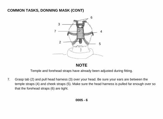
Temple and forehead straps have already been adjusted during fitting.
7. Grasp tab (2) and pull head harness (3) over your head. Be sure your ears are between the temple straps (4) and cheek straps (5). Make sure the head harness is pulled far enough over so that the forehead straps (6) are tight.
0005 - 6

0005 - 7
9
9
7
8
8. While holding head pad (7) centered on the back of the head with one hand, use the other hand to tighten cheek straps (5) one at a time, ensuring straps lay flat against your head.
9. Seal the outlet valve by pushing in on the center of the outlet valve cover (8) with one hand. Blow out hard to assure that any contaminated air is forced out around the edges of the mask (9).

COMMON TASKS, DONNING MASK (CONT) 9 11 10
10. Press palm of your hand over inlet port (10) of the canister (M40A1) or AQD opening (11) (M42A2). Breathe in lightly and hold your breath for a few seconds. Mask (9) should collapse against your face, and remain so while you hold your breath. If it does, mask is airtight and will protect you against toxic agents. If it does not, notify CBRN NCO.
0005 - 8
0005 - 9
11. Resume breathing and open eyes.
NOTE If using a QDH, go to WP 0005-37 for instructions on donning mask with QDH.
WARNING When putting on your helmet, be sure not to break the seal between your mask and the side of your face. Toxic agents could leak into your mask.
12. Put on helmet. 13. Close carrier by fastening hook and pile. 14. Continue your mission.
0005 - 10
COMMON TASKS (CONT) CHECKING MASK ASSEMBLY FOR PROPER FUNCTION
WARNING You must check your mask assembly for leaks when fitted and each time mask assembly is put on. A leaky mask assembly will not protect you from toxic agents.
NOTE Helmet should be removed before checking mask assembly for leaks, and should be donned when check is completed.
1. Don mask (WP 0005-3). 2. Press palm of your hand over inlet port (12) of canister (M40A1) or AQD opening (13) (M42A2). 3. Breathe in lightly and hold your breath for a few seconds. Mask assembly (14) should collapse
against your face, and remain so while you hold your breath. If it does, mask assembly is airtight and will protect you against toxic agents.

14
12
13
0005 - 11
0005 - 12
COMMON TASKS, CHECKING MASK ASSEMBLY FOR PROPER FUNCTION (CONT) NOTE
Leaks around the edge of your mask assembly are usually caused by bad fit. You may find a leak by feeling incoming air on your face, or you may feel a bulge at the edge of your mask assembly with your finger.
4. Check for leaks at edge of mask assembly (14) by feeling for incoming air on your face. 5. Check for bulge by running finger around edge of your mask assembly.
NOTE After each corrective action, retest using steps 2, 3, 4 and 5.
6. Get rid of leaks by making minor adjustment to straps: • To stop leaks at forehead, adjust forehead straps (15). • To stop leaks at temple, adjust temple straps (16). • To stop leaks at cheek, adjust cheek straps (17) and be sure head pad (18) is centered at the
back of your head. • To stop leaks at the throat or under the chin, lift mask assembly higher on face, seating chin
firmly. Adjusting forehead straps and cheek straps may also help.

15
14
18
16
1720
19
0005 - 13

0005 - 14
COMMON TASKS, CHECKING MASK ASSEMBLY FOR PROPER FUNCTION (CONT)
7. An air leak may be caused by an outlet valve disk that is faulty or held open by dirt. Do the following steps: • If breathing does not remove dirt, remove mask assembly (14), pull up outlet valve cover
(19), lift up outlet valve disk (20), and wipe underside of outlet valve disk with a dry, lint-free cheesecloth (item 6, WP 0013).
• If outlet valve disk is sticking, massage lightly with one finger.
8. Check to see if canister is properly installed (M40A1 – WP 0009-14) (M42A2 – WP 0009-22).
NOTE If you have a bad seal and cannot stop leak, notify CBRN NCO to repair or replace facepiece.

0005 - 15
COMMON TASKS CONNECTING AND USING THE DRINKING SYSTEM
WARNING DO NOT connect the drink tube to your canteen until all mating surfaces have been checked and are free of contamination. Chemical agents could be swallowed, resulting in sickness or death. Fill your plastic water canteen before entering contaminated area, or, if in a contaminated area, fill canteen inside a protective shelter. Care should be taken not to break the mask assembly seal while pressing in on the outlet valve cover.
NOTE Water may leak into mask assembly if mouth is taken off internal drink tube while canteen is in the raised (drinking) position. To use the drink tube, your canteen must be equipped with an M1 canteen cap.

COMMON TASKS, CONNECTING AND USING THE DRINKING SYSTEM (CONT)
0005 - 16
23
21
22
1. Press in on front of outlet valve cover (21) until internal drink tube (22) can be grasped between your teeth.
25 24
26 27
2. Steady mask assembly (23) and pull QDC (24) out of outlet valve cover. 3. Flip open cover (25) on M1 canteen cap (26). 4. Push QDC into M1 canteen cap so that pin (27) enters QDC.

WARNING If resistance is not felt, drinking system is leaking. DO NOT drink. Replace canteen. If resistance is still not felt, notify CBRN NCO for maintenance.
5. Blow to create positive pressure. You should feel some resistance. 6. If system does not leak, raise and invert canteen (28) and drink water from canteen.
28
22
7. After several swallows, stop drinking and lower canteen. Blow into internal drink tube (22) to prevent canteen from collapsing. Repeat drinking procedure as required.
0005 - 17
0005 - 18
COMMON TASKS (CONT) DISCONNECTING THE DRINKING SYSTEM
WARNING To prevent possible leakage around mask assembly, DO NOT pull on external drink tube when removing canteen.
NOTE When not in use, keep M1 canteen cap opening covered with provided flip down cover.
1. Turn canteen (29) upright. 2. Clear water from external drink tube by blowing into internal drink tube (30). 3. Firmly grasp QDC (31) and pull canteen down and away to disconnect coupling. 4. Blow to create positive pressure. You should feel some resistance. 5. Release internal drink tube from mouth. 6. Flip down cover (32) on M1 canteen cap (33) before stowing. 7. Push QDC back into retainer (34) on outlet valve cover (35).

0005 - 19
30
34
35
29 3132 33

0005 - 20
COMMON TASKS (CONT) CHECKING DRINKING SYSTEM FOR PROPER FUNCTION
1. Connect and use drinking system (WP 0005-15). 2. Disconnect drinking system (WP 0005-18). 3. Grasp internal drink tube (36) between your lips.
WARNING If resistance is not felt, drinking system is leaking. Notify CBRN NCO for maintenance.
4. Blow into internal drink tube (36). If resistance is not felt, drinking system is leaking. Notify CBRN NCO for maintenance.
5. A more positive test may be done on the external drink tube QDC by the following procedure: a. Fill cup (37) full of water. b. Place mask assembly (38) on face. c. Dip QDC (39) in cup filled with water. d. Blow into internal drink tube. e. Watch for bubbles in water. If no bubbles, QDC is operational. If bubbles are detected, the
QDC is not operational. Notify CBRN NCO for maintenance.
38
39
37
36
0005 - 21

COMMON TASKS (CONT) WEARING YOUR CARRIER (THREE WAYS)
40
43
41
42
1. The shoulder carry method is as follows: a. Attach shoulder strap D-ring (40) to hook (41) on mask carrier and adjust. b. Hook waist strap (42) to round ring (43) and adjust.
0005 - 22

2. The leg carry method is as follows: a. Put shoulder strap D-ring (40) around waist and attach to hook (41) on mask carrier and
adjust.
40
43
41
42
b. Bring waist strap (42) from back and around inside of leg. c. Pass waist strap through round ring (43) and hook to D-ring (40). Adjust.
0005 - 23

COMMON TASKS, WEARING YOUR CARRIER (THREE WAYS) (CONT)
3. The load bearing harness carry method is as follows:
0005 - 24
a. Attach short adjustable strap hook (44) to the eyelet of the back buckle (45) of the load bearing harness (46).
50
46
45
47
48
44
49
b. Attach short strap hook (47) to the eyelet of the left front buckle (48) of the load bearing harness.
c. Bring waist strap hook (49) from back and around inside of leg and attach to round ring (50).

CLEANING OF THE OPTICAL INSERTS
1. Optical Inserts (Wire) a. Place mask (51) on a nonabrasive surface eyelenses down.
51
0005 - 25

COMMON TASKS, CLEANING OF THE OPTICAL INSERTS (CONT) NOTE
Pull gently on optical lenses or the entire optical insert will be pulled from the mask.
b. Grasp wire nosepiece (52) and slowly pull optical lenses (53) away from mask until there is room available to wipe both sides of the lenses.
c. Clean the optical lenses with a cheesecloth (item 6, WP 0013). d. Push gently on wire nosepiece until the optical lenses snap back into place.
52
0005 - 26
53
53

2. Optical Inserts (Plastic) a. Place mask (54) on a nonabrasive surface eyelenses down.
0005 - 27
54 55 56
b. Fold up one optical lens (55). c. Clean the optical lens with a cheesecloth (item 6, WP 0013). d. Fold down the clean optical lens and fold up the other optical lens (56). e. Clean the optical lens with a cheesecloth (item 6, WP 0013). f. Fold down the optical lens.

M40A1 PECULIAR TASKS REMOVING MASK
NOTE If using a mask with a QDH, refer to WP 0005-39. If using JSLIST, refer to JSLIST manual (TM 10-8415-220-10) for removing instructions.
58
57
59
601. Remove helmet. 2. Loosen cheek straps (57). 3. Place one hand on the front voicemitter
(58) to hold mask assembly on face and with other hand grasp head harness tab (59) and pull the head harness (60) over the front of the mask assembly and remove mask assembly.
4. Replace helmet.
0005 - 28

0005 - 29
WARNING
M40A1 PECULIAR TASKS STOWING MASK AND ADDITIONAL AUTHORIZED ITEMS
Any solid matter ill cause leakage. under outlet valve disk w
CAUTION Abrasives such as sand and grit lenses. Be sure that outserts are will scratch eyeinstalled on the mask assembly in the mask carrier.
Check that clear outserts (61) are installed on mask assembly1. (62) (WP 0009-3). 2. Check that the second skin/universal second skin (63) is installed on the mask assembly (WP
0009-8). 3. Check that your mask assembly is dry and free of oil and solvents before stowing (WP 0009-16). 4. Check that interior of mask carrier (64) is free of dirt and trash or other unauthorized items.

M40A1 PECULIAR TASKS, STOWING MASK AND ADDITIONAL AUTHORIZED ITEMS (CONT)
63
61
62
64
0005 - 30

0005 - 31
CA N UTIO
To avoid damage to the mask as y authorized items in your mask sembly, put onlth rubber ring rocarrier. DO NOT stow outserts wi lled over the front of the outsert.
neutral gray outserts (65) in the left pocket. Stow the operator’s cards (66) and operato5. Stow r's manual (67) in the right pocket of the mask carrier (64). Stow the waterproof bag (68) in the left pocket. If issued, stow the M7 audio frequency amplifier (69) in the outside bottom pocket and the ballistic outserts (70) in the left pocket. If issued, stow the M8 detector paper (71) and Nerve Agent Antidote Kits (NAAK Mark I) (72) in the middle pocket; stow Convulsive Antidote for Nerve Agent (CANA) (73) in the right pocket.

M40A1 PECULIAR TASKS, STOWING MASK AND ADDITIONAL AUTHORIZED ITEMS (CONT)
0005 - 32
72 71
73 65
70
67
66
7 68
69

6. Pull head harness (74) over front of mask assembly (75).
74 75
CAUTION Make sure the inside surface of the mask assembly is smooth and there is no distortion. Stowage of the mask assembly without smoothing inner surfaces may result in creases which may leak.
0005 - 33

M40A1 PECULIAR TASKS, STOWING MASK AND ADDITIONAL AUTHORIZED ITEMS (CONT)
767577
78
7. Smooth the second skin/universal second skin (76) over the front of the mask assembly (75). 8. Pull the forehead straps (77) tight over the second skin/universal second skin by pulling the head
harness down as far as possible by pulling on the harness tab (78).
CAUTION To avoid damage to the mask assembly, DO NOT fold mask assembly when placing it in the mask carrier.
0005 - 34

NOTE If stowing M40A1 with QDH, see WP 0005-36.
9. Hold the facepiece assembly up and put it in the mask carrier (79) with the lenses facing away from your body.
CAUTION It is important to completely close the hook and pile fastener on the mask carrier cover. Failure to do this will result in collection of debris and damage to the mask assembly.
10. Close the mask carrier. Seal the entire hook and pile fastener surface. 79
NOTE Whenever possible, store your mask assembly in closed mask carrier in a cool, dry place. It is preferable to hang the mask carrier by the shoulder strap or the hook on the short strap.
0005 - 35

M40A1 PECULIAR TASKS STOWING M40A1 MASK WITH QUICK DOFF HOOD
1. Hold front of mask assembly in a horizontal position and smooth the QDH over it. 2. Store the ends of the underarm straps (80) in a "V". 3. Fold the two edges of the QDH (81) over the underarm straps to create a "V". 4. Fold the "V" up to cover the eyelenses. Do not let the QDH cover the chin opening. 5. Proceed to step 9, WP 0005-35.
80
81
0005 - 36

M42A2 PECULIAR TASKS DONNING MASK WITH THE QUICK DOFF HOOD
CAUTION Be careful when pulling on QDH. The QDH could snag on the buckles of the head harness and tear.
1. Perform Common Donning Mask steps 1 through 11 (WP 0005-3).
2. With both hands inside the QDH (82), expand the elastic gathering (83) around the neck of the QDH, stretch and carefully pull QDH over your head so that the QDH covers the head, neck, and shoulders.
0005 - 37
83
82

M42A2 PECULIAR TASKS, DONNING MASK WITH THE QUICK DOFF HOOD (CONT)
3. Fasten and adjust the underarm straps (84). 4. Continue Common Donning Mask procedures (WP 0005-9), starting with step 12.
84
84
0005 - 38
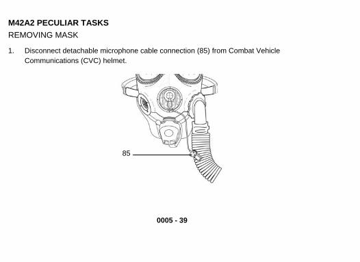
M42A2 PECULIAR TASKS REMOVING MASK
1. Disconnect detachable microphone cable connection (85) from Combat Vehicle Communications (CVC) helmet.
85
0005 - 39

0005 - 40
SK (CONT)
3. Unfasten underarm straps on the hood (86).
M42A2 PECULIAR TASKS, REMOVING MA
2. Remove helmet.
CAUTION Be very careful when pulling QDH forward. The hood could snag on the buckles
f the head harness and tear.
Using both hands, grasp the elastic gathering around neck (87)
o
4. above your head, and pull to the f
at the back of the QDH, raise it ront of mask assembly (88).
5. Loosen cheek straps (89). Place one hand on the front voicemitter (90) to hold mask assembly on face and with other hand grasp head harness tab (91) a
6.
and remove masknd pull the head harness (92) over the front of the mask assembly
assembly. . Replace helmet. 7

0005 - 41 0005 - 41
88
90
92
9189
87
86

0005 - 42
M42A2 PECULIAR TASKS TOWING MASK AND ADDITIONAL AUTHORIZED ITEMS
WARNING S
Any solid matter ill cause leakage.
CA N under outlet valve disk w
UTIO Abrasives such as sand and grit will eyelenses. Be sure that outserts are installed on the mask assembly r.
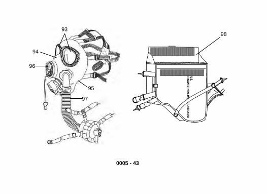
1. Check that clear outserts (93) are installed on mask assembly (94) (WP 0009-3). 2. Check that the second skin/universal second in (95) is on the mask assembly (WP 0009-8). 3. Check that the detachable microphone (96) he mask assembly (WP 0009-20). 4. Check that the hose assembly (97) is properl ecured to the mask assembly (WP 0009-26) 5. Check that your mask assembly is dry and clean before stowing. 6. Check that interior of mask carrier (98) is free of dirt and trash or other unauthorized items.
scratch in the mask carrie
sk is on t
y s
0005 - 43
9893
94
96
95
97
0005 - 44
OM42A2 PECULIAR TASKS, STOWING MASK AND ADDITIONAL AUTHORIZED ITEMS (C NT)
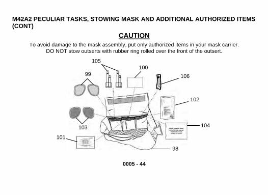
CAUTION To avoid damage to the mask assembly, put only authorized items in your mask carrier.
DO NOT stow outserts with rubber ring rolled over the front of the outsert.
105
101
106 99100
102
104103
98

0005 - 45
s
8.
CA N
7. Stow neutral gray outserts (99) in the left pocket. Stow the operator’s cards (100) and operator'manual (101) in the center pocket of the mask carrier (98). Stow the waterproof bag (102) in the ight pocket. r If issued, stow the ballistic outserts (103) in the left pocket. If issued, stow the M8
detector paper (104) and Nerve Agent Antidote Kits (NAAK Mark I) (105) in the left pocket; stowConvulsive Antidote for Nerve Agent (CANA) (106) in the right pocket. Pull head harness (107) over front of mask assembly (94).
UTIO Make sure the inside surface of the mask assembly is smooth and there is no distortion. Stowage of the mask without smoothing inner surfaces may result in creases which may leak.
107
94
0005 - 46
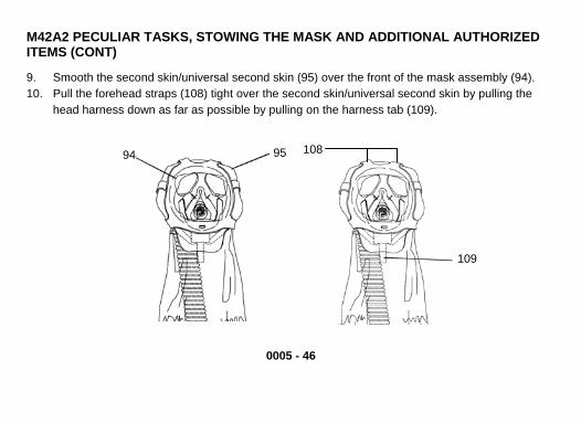
9. 10. Pull the forehead straps (108) tight over the second
head harness down as far as possible by pulling o
M42A2 PECULIAR TASKS, STOWING THE MASK AND ADDITIONAL AUTHORIZED ITEMS (CONT)
Smooth the second skin/universal second skin (95) over the front of the mask assembly (94). skin/universal second skin by pulling the
n the harness tab (109).
109
108 294 95
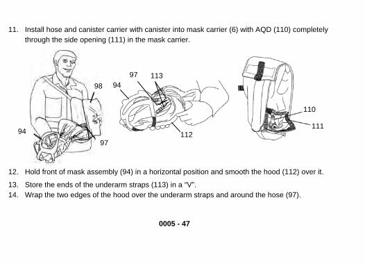
11. Install hose and canister carrier with canister into mask carrier (6) with AQD (110) completely through th sie de opening (111) in the mask carrier.
0005 - 47
12. Hold front of mask assembly (94) in a horizontal position and smooth the hood (112) over it.
13. Store the ends of the underarm straps (113) in a “V”. 14. Wrap the two edges of the hood over the underarm straps and around the hose (97).
97
945 113
112
9798
110
11194

0005 - 48
TH ASK AND ADDITIONAL AUTHORIZED
h hose to point down toward the chin (114).
E MM42A2 PECULIAR TASKS, STOWINGITEMS (CONT)
15. Grasp the hose (97) through the ood and align the16. Fold
the hose into the inside of the mask assembly (94).
115 2 94
114
97

0005 - 49
CAUTION
assembly, DO NOT fold mask assembly when
placing it in the mask carrier.
17. Gras18. mask carrier (98) with eyelenses facing away from body.
CAUTION
To avoid damage to the mask
p the hose (97) and mask (94) at the eyelenses (115). Insert the mask assembly into the
It is important to completely close the hook and pile fastener on the mask carrier cover. Failure to do this will result in collection of debris and damage to the mask assembly.
19. Close the mask carrier (98). Seal the entire hook and pile fastener surface.

0005 - 50
M42A2 PECULIITEMS (CONT)
20. Close outside AQD pocket (116).
NOTE Whenever possible, store your mask assembly in closed mask carrier in a cool, dry place. It is preferable to hang the mask carrier by the shoulder strap or the hook on the short strap.
AR TASKS, STOWING THE MASK AND ADDITIONAL AUTHORIZED
98
94
97
116
98

0005 - 51/ 52 BLANK
21. Remove the canister carrier from the mask carrier. 22. Snap the shoulder strap hook (117) into the D-ring (118) and place the shoulder strap over the
head and on the right shoulder and adjust the strap. 23. Place the waist strap (119) around your waist and snap the hook (120) into the D-ring (118) and
adjust.
END OF WORK PACKAGE
117
120
118
119
118


0006 - 1
OPERATION UNDER UNUSUAL CONDITIONS 0006
OPERATION IN UNUSUAL WEATHER This section applies to both the M40A1 and the M42A2 masks.
CAUTION Keep canister dry. Excessive moisture could clog filter canister or saturate absorbent material and make it useless.
GENERAL INSTRUCTIONS YOU MUST FOLLOW IN COLD WEATHER
1. During periods between repeated uses, take mask assembly out of carrier and shake or flex mask assembly to remove ice and snow.
CAUTION DO NOT warm up the mask assembly near a heater or open flame. The plastic and rubber parts of mask assembly could be damaged.
2. Warm mask assembly when you can.
GENERAL INSTRUCTIONS YOU MUST FOLLOW IN COLD WEATHER (CONT)
0006 - 2
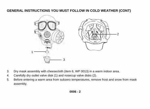
3. Dry mask assembly with cheesecloth (item 6, WP 0013) in a warm indoor area. 4. Carefully dry outlet valve disk (1) and nosecup valve disks (2). 5. Before entering a warm area from subzero temperatures, remove frost and snow from mask
assembly.
1
3
2

0006 - 3
PUTTING ON MASK IN COLD WEATHER Perform the normal procedure for donning mask (WP 0005-3), but keep in mind the following points in cold weather.
1. Remove helmet and gloves and make other adjustments to your garments as necessary to put on your mask properly.
WARNING In cold weather DO NOT clear mask by exhaling a large volume of air. Moist air will frost eyelenses and impair vision.
2. Exhale slowly and lightly. If you feel resistance when exhaling, the outlet valve disk may be sticking. 3. If outlet valve disk (1) sticks to outlet valve seat, do the following:
a. Lift bottom of outlet valve cover (3). b. Massage outlet valve disk with one finger, only when you exhale, until outlet valve disk
functions properly. c. Reseat bottom of outlet valve cover. d. Check your mask assembly for proper function (WP 0005-10). e. Resume normal breathing. f. Put on your gloves, mittens, and helmet as necessary.

0006 - 4
REMOVING MASK IN COLD WEATHER WARNING
If you become overheated in extremely cold weather, do not remove your mask outdoors until your face and head have cooled and any sweat has dried. Frostbite may result if mask is removed while your face is still wet.
1. Remove helmet and gloves and make other adjustments to garments as necessary to remove mask properly.
2. Remove mask and shake frost and snow from the mask. 3. Stow mask (M40A1 – WP 0005-29) (M42A2 – WP 0005-42). 4. Put on your gloves and helmet as necessary.
END OF WORK PACKAGE

0007 - 1 / 2 BLANK
CHAPTER 3. TROUBLESHOOTING PROCEDURES TROUBLESHOOTING PROCEDURES 0007 Perform PMCS procedures (WP 0008-5, Table 1).
END OF WORK PACKAGE

0008 - 1
CHAPTER 4. OPERATOR MAINTENANCE INSTRUCTIONS OPERATOR PREVENTIVE MAINTENANCE CHECKS AND SERVICES (PMCS) 0008
INTRODUCTION TO PMCS TABLE GENERAL The Operator Preventive Maintenance Checks and Services (PMCS) table has been provided so you can keep your equipment in good operating condition. The PMCS table is arranged to provide procedures for checks and services to be performed before, during, and after operation of the mask. A thorough initial inspection to include sizing, fitting, fit testing, and after use inspection is critical to ensure it is providing you with maximum protection. If you have not used your mask for a lengthy period of time, specific checks are required in addition to the before checks to assure that your mask is ready to be used. Shortcomings which DO NOT limit the equipment operational capability (form, fit, or function) are not noted in this TM. These minor discrepancies should be attended to and maintained to prevent them from becoming deficiencies. The following paragraphs provide information on how to use the PMCS tables. Report any malfunctions or failures on DA Form 2404, or refer to DA PAM 738-750.

0008 - 2
INTRODUCTION TO PMCS TABLE (CONT) INSPECTIONS The most detailed inspection and PMCS of your mask is accomplished after each time you use it and when you first receive it. The BEFORE, DURING and AFTER PMCS checks are designed to assure that the mask is ready for use without causing you to spend a lot of time on your mask before beginning a mission. Therefore, it is vital, for your safety, that you perform all of the checks in the interval listed. BEFORE PMCS assure that all the parts of your mask are present and verify the most important components of the mask are operational. The DURING PMCS procedures check those items which are most readily checked while operating the mask. The AFTER PMCS procedures provide a detailed check of the mask to assure that any items which are not performing properly are repaired prior to any additional use. In the event that you have not used your mask for a lengthy period of time, perform all BEFORE, DURING, and AFTER PMCS prior to using the mask. This will allow you to correct any problems which may have occurred during storage. WARNINGS AND CAUTIONS WARNINGs and CAUTIONs appear before the applicable procedures. You must observe all WARNINGs and CAUTIONs to prevent serious injury to yourself or others and to prevent damage to your equipment.
PMCS PROCEDURES The following paragraphs describe the information presented in each column of the PMCS table.

0008 - 3
ITEM NUMBER COLUMN Numbers in this column are for reference. Item numbers also appear in the order that you must do checks and services for the intervals listed. Record any faults that you discover before, during, or after operation. You DO NOT need to record faults that you fix. INTERVAL COLUMN This column tells you when you must do the procedure in the procedure column. Do your BEFORE PMCS just before you operate the mask or deploy. Do your DURING PMCS while you are using the mask. Do your AFTER PMCS right after use or before you store it. ITEM TO CHECK/SERVICE COLUMN This column identifies the item to be checked or serviced. PROCEDURE COLUMN This column gives the procedure you must do to check or service the item listed in the Item to Check/Service column. This will tell you if the equipment is ready or available for the intended mission or for operation. You must do the procedure at the time stated in the interval column. NOT FULLY MISSION CAPABLE IF: COLUMN Information in this column only tells you what deficiencies will keep your mask from being capable of operating safely. DO NOT use your mask if a check and service shows a fault listed in this column. Shortcomings or minor discrepancies which DO NOT limit operational capability or safety of use may require corrective actions and Continued surveillance, but does not “deadline” the mask.

0008 - 4
PMCS PROCEDURES (CONT) OTHER TABLE ENTRIES Be sure to observe all special information and notes that appear in your table.
NOTE
Within each section of the PMCS table, tasks are divided into those which are common to both the M40A1 and M42A2, as well as those peculiar only to the M42A2. Perform all tasks which are common and peculiar to your mask.
INDEX PAGE
Before PMCS Common ............................................................................................................. 0008 – 5 Before PMCS M42A2 Peculiar................................................................................................. 0008 – 10 During PMCS Common ......................................................................................................... 0008 – 11 During PMCS M42A2 Peculiar................................................................................................. 0008 – 12 After PMCS Common .............................................................................................................. 0008 – 13 After PMCS M42A2 Peculiar.................................................................................................... 0008 – 24
0008 - 5
TABLE 1. PREVENTIVE MAINTENANCE CHECKS AND SERVICES (PMCS). ITEM NO. INTERVAL ITEM TO
CHECK / SERVICE PROCEDURE NOT FULLY MISSION CAPABLE IF:
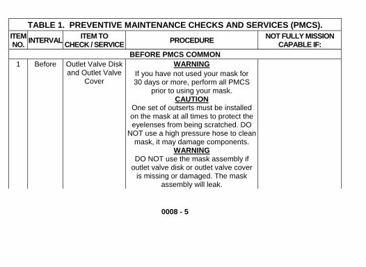
BEFORE PMCS COMMON 1 Before Outlet Valve Disk
and Outlet Valve Cover
WARNING If you have not used your mask for 30 days or more, perform all PMCS
prior to using your mask. CAUTION
One set of outserts must be installed on the mask at all times to protect the eyelenses from being scratched. DO
NOT use a high pressure hose to clean mask, it may damage components.
WARNING DO NOT use the mask assembly if
outlet valve disk or outlet valve cover is missing or damaged. The mask
assembly will leak.

0008 - 6
TABLE 1. PMCS––CONT. ITEM NO. INTERVAL ITEM TO
CHECK / SERVICE PROCEDURE NOT FULLY MISSION CAPABLE IF:
1 Before Outlet Valve Disk and Outlet Valve
Cover (Cont)
WARNING DO NOT use tissue paper or a paper towel to remove dirt or moisture from
outlet valve cover, outlet valve disk, or outlet valve seat. Paper may break up
and lodge in outlet valve area, causing leakage.
a. Grasp tab at bottom of outlet valve cover (1) and lift bottom portion of outlet valve cover. Look at outlet valve disk (2) for nicks, tears, or rips. Check to see if outlet valve disk is dirty. Wipe off moisture from outlet valve disk with a clean cheesecloth (item 6, WP 0013). Smooth outlet valve disk so it lies flat on outlet valve seat (3).
Outlet valve disk is missing, sticking, nicked, torn, ripped, dirty and cannot be cleaned or will not seat properly.

0008 - 7
TABLE 1. PMCS––CONT. ITEM NO. INTERVAL ITEM TO
CHECK / SERVICE PROCEDURE NOT FULLY MISSION CAPABLE IF:
b. Check outlet valve seat for dirt (clean as required), nicks, or cracks.
Outlet valve seat is dirty and cannot be cleaned; nicked or cracked.
c. Check outlet valve cover for cuts, tears, or holes. Look at inside of outlet valve cover for dirt or moisture. Wipe off any dirt or moisture with a soft, clean dry cheesecloth (item 6, WP 0013).
Outlet valve cover is cut, torn, has holes, or will not seat firmly over outlet valve.
3
2
1

0008 - 8
TABLE 1. PMCS––CONT. ITEM NO. INTERVAL ITEM TO
CHECK / SERVICE PROCEDURE NOT FULLY MISSION CAPABLE IF:
2 Before Facepiece and Components
Check to see that the following components are present: External Drink Tube (4) Black/Green Durability Band (Retaining Clamp) (5) Second Skin (6) One set of Outserts (7) Internal Drink Tube (8) Optical Inserts (9) (if required) M1 Waterproof Bag (10)
Any components are missing.
NOTE If you have a M42A2 mask, do the
BEFORE PMCS M42A2 PECULIAR (WP 0008-10) before you do step 3.

TABLE 1. PMCS––CONT.
0008 - 9
ITEM NO. INTERVAL ITEM TO
CHECK / SERVICE PROCEDURE NOT FULLY MISSICAPABLE IFCAPABLE IF
ON :
ON :
3 Before Mask Assembly Check your mask assembly for proper
function (WP 0005-10). Mask assembly does not function.
8
9
45
10
6
7

TABLE 1. PMCS––CONT. ITEM NO. INTERVAL ITEM TO
CHECK / SERVICE PROCEDURE NOT FULLY MISSION CAPABLE IF:
BEFORE PMCS M42A2 PECULIAR 1 Before Facepiece and
Components Check to see that the following components are present: Detachable Microphone (11) Hose Assembly (12) Attached Canister Carrier (13) QDH (14)
Any components are missing.
13
14
12
11
0008 - 10

0008 - 11
TABLE 1. PMCS––CONT. ITEM NO. INTERVAL ITEM TO
CHECK / SERVICE PROCEDURE NOT FULLY MISSION CAPABLE IF:
DURING PMCS COMMON 1 During Front and Side
Voicemitters Check to see that the front and side voicemitters are functioning properly.
Unable to communi-cate through the front and side voicemitters.
2 During External and In-ternal Drink
Tubes
Check to see that you are able to drink while wearing the mask (WP 0005-15).
Unable to drink while wearing the mask.
3 During Eyelenses and Outserts
Check to see that you can see well through the eyelenses and outserts.
Unable to see well through the eyelenses and outserts.
4 During Optical Inserts (if required)
Check to see that you can see well through the optical inserts.
Cannot see well through optical inserts.
NOTE Clean mask before performing AFTER
PMCS COMMON (WP 0008-13).

0008 - 12
TABLE 1. PMCS––CONT. ITEM NO. INTERVAL ITEM TO
CHECK / SERVICE PROCEDURE NOT FULLY MISSION CAPABLE IF:
DURING PMCS M42A2 PECULIAR 1 During Detachable
Microphone Check detachable microphone for proper operation by connecting to the Combat Vehicle Communications (CVC) helmet and activating vehicle communications system.
Unable to communi-cate through the detachable micro-phone.
2 During Hose Assembly Check to see that you are able to connect to the vehicle gas particulate filter system.
Unable to connect to the vehicle gas par-ticulate filter system.

TABLE 1. PMCS––CONT. ITEM NO. INTERVAL ITEM TO
CHECK / SERVICE PROCEDURE NOT FULLY MISSION CAPABLE IF:
AFTER PMCS COMMON
1617 15
18
1 After Canister a. Remove canister (15) (WP 0008-22, M40A1) (WP 0008-30, M42A2). Check canister, especially around seams, for cracks, dents, or holes. Check air in-take (16) to make sure it is not clog-ged with dirt.
Canister is cracked or dented over 1/4" deep, damaged on a seam, or has holes. Air intake is clogged with dirt.
b. Check for damaged threads (17) and contact surface (18) on canister.
Threads or contact surface on canister are damaged.
c. Shake canister and listen for signs of loose absorbent particles.
Loose particles rattle or dust falls out when canister is shaken.
d. See FM 3-11.4 for canister replacement criteria.
Canister replacement criteria have been exceeded.
0008 - 13

0008 - 14
TABLE 1. PMCS––CONT. ITEM NO. INTERVAL ITEM TO
CHECK / SERVICE PROCEDURE NOT FULLY MISSION CAPABLE IF:
2 After Eyelenses, Eyerings, and
Outserts
CAUTION Care must be taken not to scratch the eyelenses and outserts when handling
the facepiece assembly.
a. Remove outserts from facepiece assembly (WP 0009-3). Check eyelenses (19) for cracks, cuts, scratches, or stains that affect vision.
Eyelenses are cracked, cut, scratched, or stained enough to affect vision.
b. Check eyerings (20) for damage/distortion.
Eyerings are damaged/distorted enough to affect seal.
19

TABLE 1. PMCS––CONT. ITEM NO. INTERVAL NOT FULLY MISSION
CAPABLE IF:
0008 - 15
ITEM TO CHECK / SERVICE PROCEDURE
c. Check all outsert lenses (21) for cracks, chips, or discoloration that affect Warfighter’s vision. Check rubber rings (22) for tears, looseness, soft or cracked rims.
Outserts are broken, distorted or discolored enough to affect vi-sion. Rubber rings are torn, cracked, or loose.
3 After Quick Doff Hood If your mask was provided with a QDH, see AFTER PMCS M42A2 PECULIAR (WP 0008-35).
22
2120

0008 - 16
TABLE 1. PMCS––CONT. ITEM NO. INTERVAL ITEM TO
CHECK / SERVICE PROC ON F: EDURE NOT FULLY MISSI
CAPABLE I4 After Second Skin/
Universal Second Skin
a. Remove the hose assembly (WP 0009-26) (M42A2) or canister (WP 0009-14) (M40A1), outlet valve cover (WP 0009-4) and remove the second skin/universal second skin (WP 0009-6).
b. Visually inspect surfaces of second skin/universal second skin (1) for dirt, mud, and greasy or oily substances.
23

TABLE 1. PMCS––CONT. ITEM NO. INTERVAL ITEM TO
CHECK / SERVICENOT FULLY MISSION
CAPABLE IF:
0008 - 17
PROCEDURE
c. Check second skin/universal second skin for holes, tears, and splits. Look closely at edges of second skin/universal second skin.
Second skin/ universal second skin has holes, tears, or splits.
5 After Facepiece Assembly
a. Visually inspect inside surfaces of facepiece assembly (24) for dirt, mud, and greasy or oily substances.
Facepiece is dirty enough to affect facepiece assembly seal or proper function.
24

0008 - 18
TABLE 1. PMCS––CONT. ITEM NO. INTERVAL ITEM TO
CHECK / SERVICE PROCEDURE NOT FULLY MISSION CAPABLE IF:
5 After Facepiece Assembly (Cont)
b. Check facepiece assembly for holes, cuts, tears, splits, and nicks by holding in front of a light source.
Facepiece material has holes, cuts, tears, splits, or nicks. No damage whether par-tially or fully penetra-ting the facepiece is permitted, except minor nicks on the straps and in the area within 1/2 inch (25) from the edge of the perimeter of the face-piece, provided func-tion is not affected.

0008 - 19
TABLE 1. PMCS––CONT. ITEM NO. INTERVAL ITEM TO
CHECK / SERVICE PROCEDURE NOT FULLY MISSION CAPABLE IF:
6 After Head Harness a. Check head harness (26) for loss of elasticity.
Head harness will not hold facepiece assembly firmly against face.
b. Check for dirt. Check straps (27) for cuts, tears, missing tabs, or deteriora-tion such as mildewing or fraying.
Head harness is cut, torn, frayed, has missing tabs, or has deteriorated.
c. Ensure head harness (26) is right side out by checking that the strap that joins forehead straps is outside and the head harness tab (28) is at bottom.
26
27
28
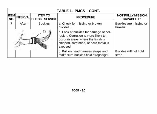
0008 - 20
TABLE 1. PMCS––CONT. ITEM NO. INTERVAL ITEM TO
CHECK / SERVICE PROCEDURE NOT FULLY MISSION CAPABLE IF:
7 After Buckles a. Check for missing or broken buckles.
Buckles are missing or broken.
b. Look at buckles for damage or cor-rosion. Corrosion is more likely to occur in areas where the finish is chipped, scratched, or bare metal is exposed.
c. Pull on head harness straps and make sure buckles hold straps tight.
Buckles will not hold strap.
29

0008 - 21
TABLE 1. PMCS––CONT. ITEM NO. INTERVAL ITEM TO
CHECK / SERVICE PROCEDURE NOT FULLY MISSION CAPABLE IF:
8 After Outlet Valve Disk and Outlet Valve
Cover
WARNING DO NOT use the mask assembly if
outlet valve disk or outlet valve cover is missing or damaged. The mask
assembly will leak.
DO NOT use tissue paper or a paper towel to remove dirt or moisture from
outlet valve cover, outlet valve disk, or outlet valve seat. Paper may break up and lodge in outlet valve area, causing
leakage.
a. Grasp tab at bottom of outlet valve cover (30) and lift bottom portion of outlet valve cover. Wipe off moisture from outlet valve disk (31) with a clean cheesecloth (item 6, WP 0013).
3132
30
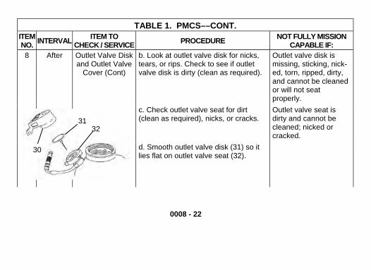
0008 - 22
TABLE 1. PMCS––CONT. ITEM NO. INTERVAL ITEM TO
CHECK / SERVICE PROCEDURE NOT FULLY MISSION CAPABLE IF:
8 After Outlet Valve Disk and Outlet Valve
Cover (Cont)
b. Look at outlet valve disk for nicks, tears, or rips. Check to see if outlet valve disk is dirty (clean as required).
Outlet valve disk is missing, sticking, nick-ed, torn, ripped, dirty, and cannot be cleaned or will not seat properly.
c. Check outlet valve seat for dirt (clean as required), nicks, or cracks.
Outlet valve seat is dirty and cannot be cleaned; nicked or cracked.
d. Smooth outlet valve disk (31) so it lies flat on outlet valve seat (32).
3231
30

0008 - 23
TABLE 1. PMCS––CONT. ITEM NO. INTERVAL ITEM TO
CHECK / SERVICE PROCEDURE NOT FULLY MISSION CAPABLE IF:
e. Check outlet valve cover (30) for cuts, tears, or holes. Look at inside of outlet valve cover for dirt or moisture. Wipe off any dirt or moisture with a soft, clean, dry cheesecloth (item 6, WP 0013).
Outlet valve cover is cut, torn, has holes, or will not seat firmly over outlet valve.
f. Reinstall outlet valve cover (WP 0009-6).
9 After Internal and External Drink
Tubes
a. Check that internal drink tube (33), external drink tube (34), and QDC (35) are present. Look for cracks or cuts on internal/external drink tubes.
Internal drink tube, external drink tube or QDC is missing or has cuts or cracks.
b. Check the external drink tube and QDC for leaks, dirt or damaged areas.
External drink tube or QDC leaks, is dirty, or is damaged.

0008 - 24
TABLE 1. PMCS––CONT. ITEM NO. INTERVAL ITEM TO
CHECK / SERVICE PROCEDURE NOT FULLY MISSION CAPABLE IF:
9 After Internal and External Drink Tubes (Cont)
c. Check QDC and external drink tube for tight connections.
QDC or external drink tube is loose.
d. Check the QDC elbow (36) for a bend that affects drinking system or does not allow the QDC to be stowed.
Drinking system restricted or QDC cannot be stowed.
e. Check for cracking and/or separation of epoxy at QDC elbow
Cracks or separation in QDC elbow exists.
f. Check the drinking system for proper function (WP 0005-20).
Drinking system leaks.
3436
35
33

0008 - 25
TABLE 1. PMCS––CONT. ITEM NO. INTERVAL ITEM TO
CHECK / SERVICE PROCEDURE NOT FULLY MISSION CAPABLE IF:
10 After Airflow Deflector a. Check that airflow deflector (37) is securely mounted inside facepiece assembly (38), and that both buttons (39) on the airflow deflector are in the mounting holes (40) of the facepiece assembly and are not broken.
Airflow deflector is not mounted properly in facepiece assembly. Buttons are broken or will not mount in facepiece assembly.
b. Check mounting holes in facepiece assembly for cuts or tears.
Mounting holes in facepiece assembly are cut or torn.
c. Check that the size of the airflow deflector matches the size of the mask (S, M/L).
39
3937
4038

0008 - 26
TABLE 1. PMCS––CONT. ITEM NO. INTERVAL ITEM TO
CHECK / SERVICE PROCEDURE NOT FULLY MISSION CAPABLE IF:
11 After Inlet Valve Body WARNING DO NOT use mask assembly if inlet
valve body or inlet valve disk are missing. The mask assembly will leak.
a. Check that inlet valve disk (41) and inlet valve body (42) are present. Wipe off moisture from inlet valve disk with a clean cheesecloth (item 6, WP 0013).
Inlet valve disk or inlet valve body is missing.
4142

0008 - 27
TABLE 1. PMCS––CONT. ITEM NO. INTERVAL ITEM TO
CHECK / SERVICE PROCEDURE NOT FULLY MISSION CAPABLE IF:
b. Look at inlet valve disk (41) and inlet valve body (42) for nicks, tears, or rips. Check to see if inlet valve disk is dirty (clean as required). Blow on inlet valve disk to make sure it is not stuck to inlet valve body.
Inlet valve disk or inlet valve body: a. Is sticking, nicked, ripped, torn or dirty. b. Cannot be cleaned. c. Will not seat properly. d. Does not provide a sealing surface (body).
12 After Nosecup Assembly
a. Check that nosecup (43) is not pulled away from back of front voicemitter housing.
Nosecup is pulled away from front voicemitter housing.
b. Check that nosecup is seated around outlet valve body.
Nosecup not seated around outlet valve body.

0008 - 28
TABLE 1. PMCS––CONT. ITEM NO. INTERVAL ITEM TO
CHECK / SERVICE PROCEDURE NOT FULLY MISSION CAPABLE IF:
12 After Nosecup Assembly (Cont)
c. Check that nosecup and nosecup valve seats (44) are present, free of dirt and not damaged. Check nosecup for cracks, cuts, or holes. If nosecup valve seat(s) is missing or damaged, notify CBRN NCO.
Nosecup is dirty, cracked, cut, has holes in it, or not present. Nosecup valve seats are dirty or damaged.
d. Check that nosecup valve disks (45) are present. Rotate nosecup valve disks to be sure they are not stuck; check that nosecup valve disks are not curled or torn.
Nosecup valve disks are missing, curled, torn or stuck to nosecup valve seat.
e. Check that nosecup valve disks (45) are seated on inside of nosecup.
Nosecup valve disks are seated on outside of nosecup.
44
43
45

TABLE 1. PMCS––CONT. ITEM NO. INTERVAL ITEM TO
CHECK / SERVICE PROCEDURE NOT FULLY MISSION CAPABLE IF:
0008 - 29
46 47
48
49
49
13 After Front and Side Voicemitter
a. Check retaining ring (46) on front voicemitter (47) for corrosion, cracks, or nicks. Try to tighten retaining ring by turning clockwise using thumb and three fingers. If loose, report to your CBRN NCO.
Retaining ring is cracked or loose.

0008 - 30
TABLE 1. PMCS––CONT. ITEM NO. INTERVAL ITEM TO
CHECK / SERVICE PROCEDURE NOT FULLY MISSION CAPABLE IF:
13 After Front and Side Voicemitter
(Cont)
b. Check retaining ring on side voice-mitter (48) for corrosion, cracks, or nicks. Try to tighten retaining ring by turning clockwise using thumb and three fingers. If loose, report to your CBRN NCO.
Retaining ring is cracked or loose.
c. Check front voicemitter and side voicemitter for dents, cracks, or punct-ures. Make sure that the four beads (49) in the center of each voicemitter are facing out.
Front and/or side voicemitter is cracked, punctured, or installed backward.

TABLE 1. PMCS––CONT. ITEM NO. INTERVAL ITEM TO
CHECK / SERVICE PROCEDURE NOT FULLY MISSION CAPABLE IF:
14 After Carrier a. Empty carrier (50) and check inside for dirt, torn straps, or missing hardware. Make sure that required unit information is in the ID pocket (51).
Carrier straps are torn or hardware is missing.
50
52 52
51
50
51
0008 - 31

0008 - 32
TABLE 1. PMCS––CONT. ITEM NO. INTERVAL ITEM TO
CHECK / SERVICE PROCEDURE NOT FULLY MISSION CAPABLE IF:
14 After Carrier (Cont) b. Check for mildew, solvents, or abrasive materials which might harm facepiece assembly. Check seams for broken stitches.
Mildew, solvents, or abrasive materials are present. Seams are broken or stitching is loose.
c. Check hook and pile fasteners (52) for dirt. If dirty, clean with a stiff bristle brush (item 3, WP 0013). Make sure hook and pile fasteners are secure on flap.
Hook and pile fasteners are loose or clogged with dirt.

0008 - 33
TABLE 1. PMCS––CONT. ITEMNO.
TO RVICE PROCEDURE NOT FULLY MISSION
CAPABLE IF: INTERVAL ITEM
CHECK / SE15 After Waterproof Bag a. Check waterproof bag (1) for
cracks, tears, holes, and/or brittleness.
Waterproof bag is torn, has holes, or is brittle.
b. Check that rubber bands (2) are in bag and are not sticky, broken, or brittle.
Rubber bands are missing or are sticky, broken, or brittle.
2
1

0008 - 34
TABLE 1. PMCS––CONT. ITEM NO. INTERVAL ITEM TO
CHECK / SERVICE PROCEDURE NOT FULLY MISSION CAPABLE IF:
16 After Mask Assembly NOTE If you have an M42A2 mask, do the AFTER PMCS M42A2 PECULIAR
before you do step 16. Make sure that you reinstall the follow- ing items prior to performing step 16: Outlet valve cover (WP 0009-4) Outserts (WP 0009-3) Second Skin/Universal Second Skin (WP 0009-6) Canister (M40A1, WP 0009-14) (M42A2, WP 0009-22).
a. Check mask assembly for proper function (WP 0005-10). Stow M40A1 mask (WP 0005-29) or M42A2 mask (WP 0005-41) after completion of test for proper function (WP 0005-10).
Proper seal cannot be obtained.

0008 - 35
TABLE 1. PMCS––CONT.
ITEM NO. INTERVAL ITEM TO
CHECK / SERVICE PROCEDURE NOT FULLY MISSION CAPABLE IF:
AFTER PMCS M42A2 PECULIAR 1 After Hose Assembly WARNING
It is important to properly clean your mask. A dirty mask will compromise
its ability to provide maximum protection.
a. Check hose assembly (53) for splits, cracks, or breaks.
Hose is cracked or broken.
b. Pull gently on hose to make sure that the star knob (54) will not pull loose from hose assembly.
Star knob pulls loose from hose assembly.

0008 - 36
TABLE 1. PMCS––CONT. ITEM NO. INTERVAL ITEM TO
CHECK / SERVICE PROCEDURE NOT FULLY MISSION CAPABLE IF:
1 After Hose Assembly(Cont)
c. Remove canister (WP 0009-22). Check that the gasket (55) is present. Check threads on canister connector hose fitting (56) for damage or dirt. Gently pull on filter canister connector hose fitting to make sure it will not pull free from the hose.
Gasket is missing. Canister connector hose fitting threads are damaged or dirty. Canister connector hose fitting pulls free from hose.
d. Unscrew star knob from facepiece assembly. Check threads (57) on the star knob for damage or dirt.
Thread on star knob is damaged or dirty.
54
55
53
5657
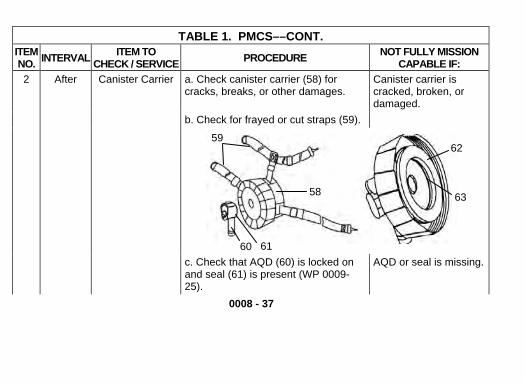
0008 - 37
TABLE 1. PMCS––CONT. ITEM NO. INTERVAL ITEM TO
CHECK / SERVICE PROCEDURE NOT FULLY MISSION CAPABLE IF:
2 After Canister Carrier a. Check canister carrier (58) for cracks, breaks, or other damages.
Canister carrier is cracked, broken, or damaged.
b. Check for frayed or cut straps (59).
c. Check that AQD (60) is locked on and seal (61) is present (WP 0009-25).
AQD or seal is missing.
58
62
63
59
6160

0008 - 38
TABLE 1. PMCS––CONT. ITEM NO. INTERVAL ITEM TO
CHECK / SERVICE PROCEDURE NOT FULLY MISSION CAPABLE IF:
2 After Canister Carrier (Cont)
d. Check that gasket (62) is present and not separated from the plastic slip ring (63).
Gasket is missing, cracked, or chipped.
3 After Detachable Microphone
a. Check to see that detachable microphone (64) is attached to the facepiece assembly securely and fully seated against front voicemitter (65).
Detachable micro-phone is not fully seated.
b. Check plastic retainer (66) for any damage.
Plastic retainer lost its tension or is broken.
c. Check cord (67) for breaks, cuts, or abrasions and damage to female connector (68).
Cord and/or connector is damaged.
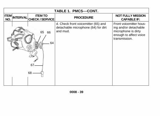
0008 - 39
TABLE 1. PMCS––CONT. ITEM INTERVAL ITEM TO NO. CHECK / SERVICE PROCEDURE NOT FULLY MISSION
CAPABLE IF: d. Check front voicemitter (65) and
detachable microphone (64) for dirt and mud.
Front voicemitter hous-ing and/or detachable microphone is dirty enough to affect voice transmission.
68
64
67
6665

TABLE 1. PMCS––CONT. ITEM NO. INTERVAL ITEM TO
CHECK / SERVICE PROCEDURE NOT FULLY MISSION CAPABLE IF:
4 After Quick Doff Hood a. Examine QDH (69) for cuts, holes, or tears.
QDH has more than two pin head size holes in any one panel. QDH has cuts, holes, or tears.
b. Check for sticky or gummy areas, peeled or worn coatings, and broken or missing straps or hardware.
QDH has sticky or gummy areas, peeled or worn coat-ings, straps are broken, or hardware is missing.
NOTE Return to AFTER PMCS COMMON
(WP-0008-16).
69
END OF WORK PACKAGE
0008 - 40

0009 - 1
OPERATOR MAINTENANCE PROCEDURES 0009
GENERAL
1. This section contains step-by-step procedures for maintaining the M40A1 and the M42A2 masks.
2. The section is divided into those tasks which are common to the M40A1 and the M42A2, those tasks which are peculiar to the M40A1, and those tasks which are peculiar to the M42A2. Common tasks are illustrated with the M40A1.
3. You, the operator, are authorized to inspect and service the mask and additionally authorized items. It is your responsibility to notify your CBRN NCO or officer of all defects and of maintenance requirements not authorized in this manual.
4. The following index will aid you in locating the proper procedure within this section:

0009 - 2
INDEX COMMON TASKS PAGE Removing and Installing the Outserts ..........................................................................................0009-3 Removing and Installing the Outlet Valve Cover ..........................................................................0009-4 Removing and Installing the Second Skin and Universal Second Skin .......................................0009-6 Mask Carrier Servicing ...............................................................................................................0009-12 M40A1 PECULIAR Removing and Installing the Canister ........................................................................................0009-14 Mask Servicing ..........................................................................................................................0009-16 M42A2 PECULIAR Removing and Installing the Detachable Microphone ................................................................0009-20 Removing and Installing the Canister ........................................................................................0009-22 Removing and Installing the Armor Quick Disconnect ...............................................................0009-25 Removing and Installing the Hose Assembly .............................................................................0009-26 Removing and Installing the Quick Doff Hood ...........................................................................0009-27 Mask Servicing ...........................................................................................................................0009-31

COMMON TASKS REMOVING AND INSTALLING THE OUTSERTS
4
3
2
11. Removal
a. Roll rubber ring (1) of outsert (2) from behind eyering (3).
b. Lift outsert from facepiece assembly (4).
c. Repeat steps a and b to remove the other outsert.
2. Installation a. Roll rubber ring forward
all around edge of outsert. b. Lay outsert over eyering and turn rubber ring down all around eyering. c. Repeat steps a and b to install the other outsert.
0009 - 3

COMMON TASKS (CONT) REMOVING AND INSTALLING THE OUTLET VALVE COVER
11 11
8
10
76
5
9
0009 - 4

0009 - 5
1. Removal a. Remove external drink tube (5) from tab (6) on outlet valve cover (7). b. Remove quick disconnect coupling (8) from the outlet valve cover retainer (9).
CAUTION To prevent tearing outlet valve cover during removal, be careful pulling outlet cover over flanges on outlet valve body.
c. Grasp tab at bottom of outlet valve cover and lift bottom portion of outlet valve cover from outlet valve body (10).
d. Pull sides of outlet valve cover away from groove around outlet valve until bottom of outlet valve cover is detached.
e. Disconnect outlet valve cover from flanges (11) on top of outlet valve body.
2. Installation a. Install outlet valve cover on flanges on top of outlet valve body. b. Using tab on bottom of outlet valve cover, pull outlet valve cover over face of outlet valve
body. Make sure outlet valve cover snaps in place around outlet valve body. c. Install quick disconnect coupling securely in outlet valve cover retainer. d. Fasten external drink tube to tab.

COMMON TASKS (CONT) REMOVING AND INSTALLING THE SECOND SKIN AND UNIVERSAL SECOND SKIN
1. Removal a. Remove canister (WP 0009-14) (M40A1 only). b. Remove hose assembly (WP 0009-26) (M42A2 only). c. Remove detachable microphone (WP 0009-20) (M42A2 only). d. Remove outserts (WP 0009-3). e. Remove outlet valve cover (WP 0009-4).
121213
0009 - 6
13 1717
15 16
18
1616
1418

0009 - 7
CAUTION Use caution when stretching second skin and universal second skin openings.
f. Stretch eyelens opening (12) of second skin or universal second skin (13), and pull second skin or universal second skin from facepiece assembly (14).
g. Stretch side port opening (15) of second skin or universal second skin, and pull second skin or universal second skin from facepiece assembly.
h. Stretch the other side port opening (16) of second skin or universal second skin, and pull second skin or universal second skin from facepiece assembly.
i. Stretch front voicemitter opening (17) of the second skin or universal second skin, and pull the second skin or universal second skin from the facepiece assembly.
CAUTION Be careful not to tear outlet valve body opening of second skin or universal second skin when pulling over flanges on outlet valve body.
j. Stretch outlet valve body opening (18) of the second skin or universal second skin, and pull the rest of the second skin or universal second skin from the facepiece assembly.

COMMON TASKS, REMOVING AND INSTALLING THE SECOND SKIN AND UNIVERSAL SECOND SKIN (CONT)
2. Installation a. Orient the second skin (19) with ridge (20) and rubber catches (21) facing outward; orient
the universal second skin (22) with ridge (20) facing outward. b. Feed the external drink tube (23) through the outlet valve body opening (24) on the second
skin or universal second skin. 21
0009 - 8
22
20 24
2026
19
2425
23
0009 - 9
CAUTION Avoid overstretching holes in the second skin or universal second skin. To prevent tearing the outlet valve cover opening of the second skin or universal second skin, be careful pulling over flanges on outlet valve body.
c. Stretch outlet valve body opening of the second skin or universal second skin, and position
it over outlet valve body (25) of facepiece assembly (26).
NOTE
There are two side openings on the second skin or universal second skin. One fits over the side voicemitter. The other fits over the side port where the canister, M40A1, or the hose, M42A2, is attached.

0009 - 10
COMMON TASKS, REMOVING AND INSTALLING THE SECOND SKIN AND UNIVERSAL SECOND SKIN (CONT)
d. Stretch side port opening (27) of the second skin or universal second skin (28), position it over the side voicemitter (29) of facepiece assembly (30).
e. Stretch the other side port opening (31) of the second skin or universal second skin, position it over the side port (32) of facepiece assembly.
f. Stretch front voicemitter opening (33) of the second skin or universal second skin, and position it over the front voicemitter (34) of facepiece assembly.
g. Stretch eyelens openings (35) of the second skin or universal second skin, and position it over the eyelenses (36) of facepiece assembly.
h. Install outlet valve cover (WP 0009-4), and outserts (WP 0009-3). i. Install canister (WP 0009-14) (M40A1 only). j. Install hose assembly (WP 0009-26), and detachable microphone (WP 0009-20) (M42A2
only).

31
35
27
33
28
31
28
33
35
27 32
30
3429
36
0009 - 11

0009 - 12
COMMON TASKS (CONT) MASK CARRIER SERVICING
WARNING DO NOT allow dirt or foreign material to remain in carrier. Dirt or foreign material in carrier may get into valves, causing them to leak.
CAUTION Abrasive material in carrier will scratch lens.
1. Remove contents from carrier (37). 2. Shake carrier upside down to remove dirt and foreign matter. 3. Soak brush (item 3, WP 0013) in cool water. 4. Shake brush to remove excess water. 5. Clean carrier with brush.

CAUTION Ensure carrier is entirely dry before stowing components.
6. Dry all surfaces of the mask carrier with a clean cheesecloth (item 6, WP 0013). Allow mask carrier to air dry before stowing the mask components.
Fig.2. M42A2 carrier Fig. 1. M40A1 carrier
37
0009 - 13

0009 - 14
M40A1 PECULIAR REMOVING AND INSTALLING THE CANISTER
WARNING HEALTH/ENVIRONMENTAL HAZARD. There are two Mask Canisters, the C2 and the C2A1. The C2 canister contains Chromium VI, and damaged or unusable canisters are considered Hazardous Waste. (Chromium VI is a known carcinogen if inhaled or swallowed.) The C2A1 canister is chromium-free but must continue to be disposed of in accordance with State and Local Environmental Laws. DO NOT throw away damaged or unusable canisters as ordinary trash. DO turn in damaged or unusable canisters to your hazardous waste management office or Defense Reutilization and Marketing Office (DRMO).
1. Removal a. Remove the canister (38) by unscrewing counterclockwise from the facepiece assembly
(39).
2. Installation

a. Ensure that the canister mating surfaces are clean. b. Position canister and screw in canister by screwing clockwise into sideport of facepiece
assembly until it makes contact with the facepiece assembly. c. Place a mark (40) on the canister and a mark on the second skin (4) (Figure 1). d. Tighten the canister an additional 1/4 to 1/2 inch to assure that leakage will not occur. e. There should now be a gap of 1/4 to 1/2 inch between the two marks (Figure 2) you made
in step c.
Figure 1. Figure 2. 41
40 4041
39
38
0009 - 15

0009 - 16
M40A1 PECULIAR (CONT) MASK SERVICING
1. Cleaning
NOTE When you clean facepiece assembly, use only potable water. See your CBRN NCO for supplies or assistance if needed.
You will need the following items to clean facepiece assembly: Alcohol (item 8, WP 0013) Pail (item 10, WP 0013) Lens Brush (item 2, WP 0013) Soap (item 13, WP 0013) Cheesecloth (item 6, WP 0013) Respirator Cleaning Wipes (item 19, WP 0013)
a. Remove canister (WP 0009-14), outserts (WP 0009-3), and QDH (if applicable) (WP 0009-27).
CAUTION Keep canister dry. Excessive moisture could clog canister or saturate absorbent material and make it useless.
b. Set canister aside, away from cleaning operations.

0009 - 17
c. Remove outlet valve cover (WP 0009-4). d. Remove second skin/universal second skin (WP 0009-6). e. If necessary, remove greasy or oily substances from your facepiece assembly (42) ,
second skin/universal second skin (43), QDH (if applicable) (44), and outserts (45), inside and out with alcohol (item 8, WP 0013) and clean cheesecloth (item 6, WP 0013) or respirator cleaning wipes (item 19, WP 0013).

M40A1 PECULIAR, MASK SERVICING (CONT)
42
4344
45
f. Clean your facepiece (42), second skin/universal second skin (43), QDH (44) if present, and outserts (45) inside and out, using clean cheesecloth (item 6, WP 0013), soap (item 13, WP 0013), and a pail (item 10, WP 0013). Dip the cheesecloth in warm, soapy water and wring cheesecloth almost dry. A soft brush (item 2, WP 0013) may also be used.
0009 - 18

0009 - 19
g. Rinse by wiping with a clean cheesecloth (item 6, WP 0013) that has been dipped in warm, clear water and wrung almost dry.
CAUTION Ensure all components are dry before stowing.
h. Dry facepiece, second skin/universal second skin, QDH if present, and outserts with cheesecloth (item 6, WP 0013) or allow to air dry.
i. Install second skin/universal second skin (WP 0009-6). j. Install outlet valve cover (WP 0009-4). k. Install QDH (WP 0009-27) if required, outserts (WP 0009-3), and canister (WP 0009-14).
2. Decontaminating
CAUTION DS2 may damage the voicemitters of the facepiece assembly. When exposed to DS2, rinse voicemitters with clean water.
a. Use the M295 according to instructions in TM 3-4230-235-10. b. Refer to Unit Standard Operating Procedures (SOP) for complete decontamination
procedures.

0009 - 20
M42A2 PECULIAR REMOVING AND INSTALLING THE DETACHABLE MICROPHONE
1. Removal a. Hold the facepiece (46) in your hand with the front voicemitter (47) facing you. b. Place index finger on either side of the detachable microphone at the three o’clock position
(48) or nine o’clock position (49). Apply a sideward force until extracted.
2. Installation a. Hold facepiece in your hand with the front voicemitter facing you. b. Hold detachable microphone clip (50) in your other hand with the ring opening facing down,
and the flat surface facing toward the facepiece. c. Insert the clip into the voicemitter housing (51) open end first with the cord (52) facing the
six o’clock position. d. Snap the clip into place, by pushing on the microphone casing (53), making sure it is flush
against the front voicemitter.
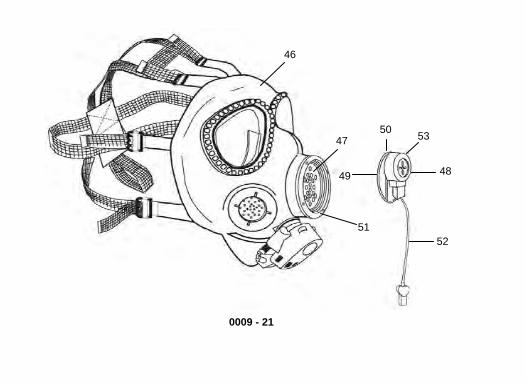
46
47
51
49
50 53
48
52
0009 - 21
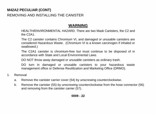
0009 - 22
M42A2 PECULIAR (CONT) REMOVING AND INSTALLING THE CANISTER
WARNING HEALTH/ENVIRONMENTAL HAZARD. There are two Mask Canisters, the C2 and the C2A1. The C2 canister contains Chromium VI, and damaged or unusable canisters are considered Hazardous Waste. (Chromium VI is a known carcinogen if inhaled or swallowed.) The C2A1 canister is chromium-free but must continue to be disposed of in accordance with State and Local Environmental Laws. DO NOT throw away damaged or unusable canisters as ordinary trash. DO turn in damaged or unusable canisters to your hazardous waste management office or Defense Reutilization and Marketing Office (DRMO).
1. Removal a. Remove the canister carrier cover (54) by unscrewing counterclockwise. b. Remove the canister (55) by unscrewing counterclockwise from the hose connector (56)
and removing from the canister carrier (57).

0009 - 23
2. Installation a. Ensure that the hose assembly mating surfaces are clean.
WARNING Make sure the gasket is present in the hose fitting before connecting the canister to the hose. A missing gasket will affect the seal and will allow the wearer to inhale contaminated air.
b. Ensure that the gasket (58) is mounted in the hose connector. c. Feed hose end connector through canister carrier. d. Install canister on the hose connector and tighten canister (clockwise) until the mating
surfaces touch. e. Make a mark (59) on the canister and a second mark (60) on the hose connector that line
up with each other (Figure 1).

M42A2 PECULIAR, REMOVING AND INSTALLING THE CANISTER (CONT)
f. Tighten the canister another 1/4 to 1/2 inch to assure leakage will not occur. There should now be a gap of 1/4 to 1/2 inch between the two marks you made in step c (Figure 2).
g. Screw canister carrier cover (54) on canister carrier (57) hand tight clockwise.
Figure 2.
57
58
56
55
54
60
5960
59
Figure 1.
0009 - 24

M42 2 PECULIAR STALLING THE ARMOR QUICK DISCONNECT
AREMOVING AND IN (AQD)
1. Removal 64
0009 - 25
a. Turn thred marking (
e lever (61) counterclockwise to uncover 62) indicating unlocked position.
b. Pull out the AQD (63) from the canister carrier cover (64).
2. Installation a. Position Ab. Make sure that A
QD (63) to the canister carrier inlet opening (65). QD is unlocked. If red mark is shown
on the side of AQD, it is unlocked. c. Snap AQD to the canister carrier cover (66).
Turn lever (61) clockwise to lock in d. place. Wheis seen, AQD is locked.
n no red
63
66 61
62
61
63
65

M42A2 PECULIAR REMOVING AND INSTALLING THE HOSE ASSEMBLY
1. Removal a. Unscrew star knob (67) to remove the hose assembly
(68) from the side port (69). b. Remove canister (WP 0009-22).
2. Installation 67a. Screw star knob clockwise into the side port to attach
the hose assembly. 69
WARNING Star knob must be tight or movement of the hose
may cause it to loosen and leak. 68
b. Tighten star knob until mask distorts. c. Install canister (WP 0009-22).
0009 - 26

M42A2 PECULIAR REMOVING AND INSTALLING THE QUICK DOFF HOOD
1. Removal a. Grasp elastic seam at 12 o’clock position (70) of QDH opening (71) and detach from the
top (72) of the second skin/universal second skin (73).
70
71
72
73
0009 - 27

M42A2 PECULIAR, REMOVING AND INSTALLING THE QUICK DOFF HOOD (CONT)
b. Pull QDH (74) to the rear of facepiece assembly (75) over the head harness (76).
NOTE Make sure that while detaching the QDH from the lower part of the second skin/universal second skin that the outlet valve cover remains in place.
c. Detach QDH from the bottom (77) of the second skin/universal second skin.
77
74
76
75
0009 - 28

2. Installation
NOTE Ensure tape on QDH faces outside.
a. Attach elastic seam at six o’clock position (78) of QDH opening (71) to bottom (77) of second skin/universal second skin (73).
0009 - 29
71
73
78
77
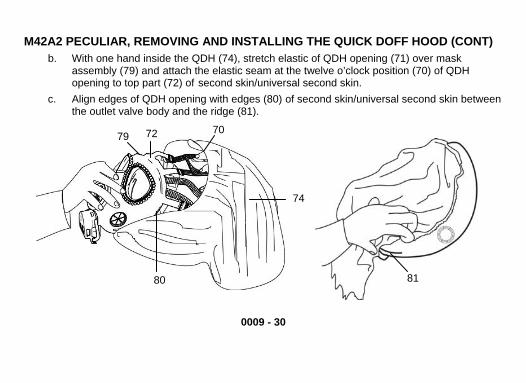
M42A2 PECULIAR, REMOVING AND INSTALLING THE QUICK DOFF HOOD (CONT) b. With one hand inside the QDH (74), stretch elastic of QDH opening (71) over mask
assembly (79) and attach the elastic seam at the twelve o’clock position (70) of QDH opening to top part (72) of second skin/universal second skin.
c. Align edges of QDH opening with edges (80) of second skin/universal second skin between the outlet valve body and the ridge (81).
74
80
7279 70
81
0009 - 30
0009 - 31
M42A2 PECULIAR MASK SERVICING
1. Cleaning
NOTE When you clean your facepiece assembly, use only potable water. See your CBRN NCO for supplies or assistance if needed.
You will need the following items to clean your facepiece assembly: Alcohol (item 8, WP 0013) Pail (item 10, WP 0013) Lens Brush (item 2, WP 0013) Soap (item 13, WP 0013) Cheesecloth (item 6, WP 0013) Respirator Cleaning Wipes (item 19, WP 0013)
a. Remove hose assembly (WP 0009-26), canister (WP 0009-22), outserts (WP 0009-3), detachable microphone (WP 0009-20) and QDH (WP 0009-27).
CAUTION Keep canister dry. Excessive moisture could clog canister or saturate absorbent material and make it useless.
b. Set canister aside, away from cleaning operations.

M42A2 PECULIAR, MASK SERVICING (CONT) c. Remove outlet valve cover (WP 0009-4). d. Remove second skin/universal second skin (WP 0009-6). e. If necessary, remove greasy or oily substances from your facepiece (82) , second
skin/universal second skin (83), QDH (84), canister carrier (85) and outserts (86), inside and out with alcohol (item 8, WP 0013) and clean cheesecloth (item 6, WP 0013) or respirator cleaning wipes (item 19, WP 0013).
84
85
86
8382
87
88
0009 - 32

0009 - 33
f. Detachable microphone (87) should be cleaned by brushing (item 2, WP 0013) or blowing off exterior surfaces and in extreme cases may be rinsed with clean water.
g. Clean your facepiece (82), second skin/universal second skin (83), QDH (84), canister carrier (85) and outserts (86) inside and out, using clean cheesecloth (item 6, WP 0013), soap (item 13, WP 0013), and a pail (item 10, WP 0013). Dip the cheesecloth in warm, soapy water and wring cheesecloth almost dry. A soft brush (item 2, WP 0013) may also be used.
h. Rinse by wiping with a clean cheesecloth (item 6, WP 0013) that has been dipped in warm, clear water and wrung almost dry.
i. Dry facepiece, second skin/universal second skin, QDH, canister carrier and outserts with cheesecloth (item 6, WP 0013) or allow to air dry.
j. Clean outside surface of hose (88), using clean cheesecloth (item 6, WP 0013), soap (item 13, WP 0013), and a pail (item 10, WP 0013). A soft brush (item 2, WP 0013) may also be used. Clean rinse and dry following the procedures in steps g, h, and i.
k. Install second skin/universal second skin (WP 0009-6). l. Install outlet valve cover (WP 0009-4). m. Install QDH (WP 0009-27), detachable microphone (WP 0009-20), outserts (WP 0009-3),
canister (WP 0009-22), and hose assembly (WP 0009-26).

0009 - 34
2. Decontaminating
CAUTION Decontamination Solution 2 (DS2) may damage the voicemitter of the facepiece assembly. When exposed to DS2, remove canister and rinse your facepiece assembly in clean water. DO NOT wet the canister. Care must be taken not to scratch the outserts or eyelenses when handling the facepiece assembly.
a. Use the M295 according to instructions in TM 3-4230-235-10. b. Refer to Unit SOP for complete decontamination procedures.
END OF WORK PACKAGE

0010 – 1
CHAPTER 5. SUPPORTING INFORMATION REFERENCES 0010
SCOPE This appendix lists all forms, field manuals, technical manuals, and miscellaneous publications referenced in this manual.
FORMS DA Form 2028 Recommended Changes to Publications and Blank Forms DA Form 2404 Equipment Inspection and Maintenance Worksheet DD Form 314 Preventive Maintenance Schedule and Record NAVMC Form 10772 Recommended Change to Publications/Logistics-Maintenance Data Coding SF 364 Report of Discrepancy (ROD) SF 368 Product Quality Deficiency Report
FIELD MANUALS FM 3-11.4 NBC Protection FM 4-25.11 First Aid for Soldiers

0010 – 2
TECHNICAL MANUALS TM 3-4240-349-12&P Operator and Unit Maintenance Manual for Protection Assessment
Test System, M41 TM 43-0002-31 Destruction of Chemical Weapons and Defense Equipment to
Prevent Enemy Use TM 4700-15/1 Ground Equipment Record Procedures TM 8415-10/3 and Operator Manual for Joint Service Lightweight Integrated Suit Technology TM 10-8415-220-10 (JSLIST) Chemical Protective Ensemble TM 10-8415-209-10/ Operator's Manual for Individual Chemical Protective Clothing TM 10-8415-10/2 Operator's Manual v2.0 for Tester, Leakage, Protective Mask: M46 (Joint Service Mask Leakage Tester [JSMLT]) NSN 6665-01-506-9002 TM 10942A-OI/1 Marine Corps TO 33A4-7-10-1 Air Force TM N65538-060017 Navy
TRAINING MATERIALS TVT 3-95 M40/M42 Protective Mask Unit Level Operations - PIN 710665 - Video Tape TVT 3-96 M40/M42 Protective Mask Operator Level Operations - PIN 710719 - Video
Tape
0010 – 3
TVT 3-97 M41 Protection Assessment Testing System (9.5 minutes) - PIN 710411 - Video Tape
AR 40-63 Ophthalmic Services NAVMED COMINST 6810.1 AR 70-38 Research, Development, Test and Evaluation of Material for Extreme
Climatic Conditions AR 700-84 Issue and Sale of Personal Clothing AR 700-138 Army Logistics Readiness and Sustainability AR 725-50 Requisition, Receipt, and Issue System CTA 8-100 Army Medical Department Expendable/Durable Items CTA 50-970 Expendable/Durable Items (Except Medical, Class V, Repair Parts, and
Heraldic items) DA PAM 738-750 Functional Users Manual for the Army Maintenance Management System
(TAMMS) DA PAM 738-751 Functional Users Manual for the Army Maintenance Management System -
Aviation (TAMMS-A) DA PAM 750-8 The Army Maintenance Management System (TAMMS) Users Manual MCO 4855.10 Product Quality Deficiency Report (PQDR) MIL-STD-129 Marking for Shipment and Storage SB 3-30-2 Chemical-Biological Canisters and Filter Elements: Serviceability Lists
Protection Assessment Test System (Provided with end item, commercial manual)

0010 – 4
WEB SITES aeps.ria.army.mil Army Electronic Product Support Website
END OF WORK PACKAGE

0011 - 1
COMPONENTS OF END ITEM AND BASIC ISSUE ITEMS LIST 0011
INTRODUCTION
SCOPE The components of end item and basic issue items for the M40A1 and the M42A2 mask are identical. This appendix lists these items to help you inventory items required for safe and efficient operation.
GENERAL
The Components of End Item and Basic Issue Items Lists are divided into the following: 1. Components of End Item (COEI). This listing is for informational purposes only, and not authority
to requisition replacements. These items are part of the end item, but are removed and separately packaged for transportation or shipment. As part of the end item, these items must be with the end item whenever it is issued or transferred between property accounts. Illustrations are furnished to assist you in identifying the items.
2. Basic Issue Items (BII). These are the minimum essential items required to place either the M40A1 or the M42A2 mask in operation, to operate it, and to perform emergency repairs. Although shipped separately packaged, BII must be with the M40A1 or the M42A2 mask during operation and whenever it is transferred between property accounts. The illustrations will assist you with hard-to-identify items. This manual is your authority to request/requisition replacement BII, based on TOE/MTOE authorization of the end item.

0011 - 2
EXPLANATION OF COLUMNS The following provides an explanation of columns found in the tabular listings: 1. Column (1) - Illustration Number (Illus Number). This column indicates the number of the
illustration in which the item is shown. 2. Column (2) - National Stock Number. Indicates the National stock number assigned to the item
and will be used for requisitioning purposes. 3. Column (3) - Description. Indicates the Federal item name and, if required, a minimum
description to identify and locate the item. The last line for each item indicates the Commercial and Government Entity Code (CAGEC) (in parentheses) followed by the part number.
4. Column (4) - Unit of Measure (U/M). Indicates the measure used in performing the actual operational/ maintenance function. This measure is expressed by a two-character alphabetical abbreviation (e.g., ea, in., pr).
5. Column (5) - Quantity required (Qty rqr). Indicates the quantity of the item authorized to be used with/on the equipment.
COMPONENTS OF END ITEM There are no components of end item required.

0011 – 3 / 4 BLANK
BASIC ISSUE ITEMS LIST Table 1. Basic Issue Items List
(1) (2) (3) (4) (5)
ILLUSTRATION NUMBER
NATIONAL STOCK
NUMBER (NSN)
DESCRIPTION, PART
NUMBER/(CAGEC) U/M QUANTITY REQUIRED
1 Operator’s Card Mask, Chemical-Biological: Field M40A1 and Combat Vehicle, M42A2, 5-1-2797/(81361) 7690-01-491-9282
EA 1
2 Operator's Manual for Chemical-Biological Mask: Field, M40A1 and Combat Vehicle, M42A2, TM 3-4240-346-10
EA 1
END OF WORK PACKAGE

0012 - 1
ADDITIONAL AUTHORIZED ITEMS LIST 0012
INTRODUCTION
SCOPE This table lists additional items which you are authorized for the support of either mask.
GENERAL This list identifies items that DO NOT have to accompany either the M40A1 or the M42A2 mask and that DO NOT have to be turned in with it. These items are authorized to you by CTA, MTOE, TDA, or JTA.
EXPLANATION OF LISTING National stock numbers, descriptions, and quantities are provided to help you identify and request the additional items you require to support this equipment. The items are listed in alphabetical sequence by item name under the type document (i.e., CTA, MTOE, TDA, or JTA) which authorizes the item(s) to you.

0012 - 2
Table 1. Additional Authorized Items List
(1) (2) (3) (4) NATIONAL
STOCK NUMBER DESCRIPTION
CAGEC AND PART NUMBER U/M QUANTITYREQUIRED
CTA AUTHORIZED ITEMS 5996-01-381-9012 AMPLIFIER, AUDIO FREQUENCY: M7
(81361) 5-1-2720-1 EA 1
8465-01-115-0026 CANTEEN, WATER, WITH M1 CANTEEN CAP (81349) MIL-C-43103
EA 1
6850-01-357-8456 DECONTAMINATING KIT, INDIVIDUAL EQUIPMENT, M295 (81361) 5-77-3201
EA 1
6850-01-276-1905 DECONTAMINATION, SKIN, M291 (81361) 5-77-2301
EA 1
4240-01-442-4810 DETACHABLE MICROPHONE, AIRCREW (81361) 5-1-3354
EA 1

0012 - 3 / 4 BLANK
Table 1. Additional Authorized Items List (Cont)
(1) (2) (3) (4) NATIONAL
STOCK NUMBER DESCRIPTION
CAGEC AND PART NUMBER U/M QUANTITYREQUIRED
4240-01-376-3152 HOOD ASSEMBLY (81361) 5-1-2701
EA 1
4240-01-389-7152 LENS, MOUNT (81361) 5-1-3021
EA 1
4240-01-434-1503 M1 LASER BALLISTIC OUTSERTS (81361) 5-1-2721
PR 1
6665-00-050-8529 PAPER, CHEMICAL AGENT DETECTOR, M8 (81361) D5-67-266
EA 1
*** INSERTS, OPTICAL* EA 1
*Availability by prescription of a medical officer or optometrist (AR 40-63)
END OF WORK PACKAGE


0013 - 1
EXPENDABLE AND DURABLE ITEMS LIST 0013
INTRODUCTION SCOPE The expendable/durable supplies and materials list is identical for the M40A1 and the M42A2 masks. This appendix lists expendable and durable items that you will need to operate and maintain the M40A1/M42A2 masks. This listing is for informational purposes only and is not authority to requisition the listed items. These items are authorized to you by CTA 50-970, Expendable/Durable Items (except medical, Class V repair parts, and heraldic items), CTA 50-909, Field and Garrison Furnishings and Equipment or CTA 8-100, Army Medical Department Expendable/Durable Items.

0013 - 2
EXPLANATION OF COLUMNS IN THE EXPENDABLE/DURABLE ITEMS LIST A. Column (1) Item No. This number is assigned to the entry in the list and is referenced in the
narrative instructions to identify the item. (e.g., Use cheesecloth (WP 0013, item 6)). B. Column (2) Level. This column identifies the lowest level of maintenance that requires the
listed item (include as applicable: C = Crew, O = Service/AMC, F = Field/ASB, H = Below Depot, D = Depot).
C. Column (3) National Stock Number (NSN). This is the NSN assigned to the item which you can use to requisition it.
D. Column (4) Item Name, Description, Part Number/(CAGEC). This column provides the other information you need to identify the item. The last line below the description is the part number and the Commercial and Government Entity Code (CAGEC) (in parentheses).
E. Column (5) U/I. Unit of Issue (U/I) code shows the physical measurement or count of an item, such as gallon (GL), dozen (DZ), gross (GZ), etc.

0013 - 3
Table 1. Expendable and Durable Items List (1) (2) (3) (4) (5)
ITEM NO. LEVEL
NATIONAL STOCK NUMBER (NSN)
ITEM NAME, DESCRIPTION, PART NUMBER/(CAGEC) U/I
1 O 6515-01-234-6838 APPLICATOR, DISPOSABLE: plastic or wood, cotton tipped (5L934) 362
EA
2 C 7920-00-205-0565 BRUSH, DUSTING, LENS, (81348) H-B-1654
EA
3 C 7920-00-061-0037 BRUSH, SCRUB: nylon bristle (81348) H-B-1490-6-P1
EA
4 O 6665-00-978-5516 BULB, ASPIRATOR (55799) BH5607
EA

0013 - 4
Table 1. Expendable and Durable Items List (Cont) (1) (2) (3) (4) (5)
ITEM NO. LEVEL
NATIONAL STOCK NUMBER (NSN)
ITEM NAME, DESCRIPTION, PART NUMBER/(CAGEC) U/I
5 O 6840-00-242-4770 CALCIUM HYPOCHLORITE, TECHNICAL: granular: 45 lb. bx. (12ea 3-3/4 lb. bt.) (81348) O-C-114
LB
O 6840-00-255-0471 6 oz. BT OZ
O 6840-00-238-8115 5 lb. BT LB
6 C 8305-00-222-2423 CLOTH, CHEESECLOTH (81348) CCC-C-440
YD
7 O 8415-00-926-6696 GLOVES, RUBBER, INDUSTRIAL (81348) ZZ-G-381
PR
8 C 6505-00-655-8366 ISOPROPYL RUBBING ALCOHOL: bottle, plastic container (1DZ38) HDX-22
PT

0013 - 5
Table 1. Expendable and Durable Items List (Cont) (1) (2) (3) (4) (5)
ITEM NO. LEVEL
NATIONAL STOCK NUMBER (NSN)
ITEM NAME, DESCRIPTION, PART NUMBER/(CAGEC) U/I
9 O 6810-00-123-7047 N-AMYL ACETATE, REAGENT: clear flammable liquid (81349) MIL C 51130
ML
10 C 7240-01-094-4305 PAIL, UTILITY: plastic, snap-on lid, 5.00 gal. (58536) A-A-332
EA
11 O 5120-00-288-8739 SCREWDRIVER, JEWELER (58536) A-A-3152
EA
12 O 5110-00-293-3444 SHEARS, STRAIGHT TRIMMERS: 6 in. (81348) GGG-S-278
EA
13 C 8520-00-228-0598 SOAP, TOILET: nonmedicated, liquid, type 1 (81348) P-S-624
GL
14 O 6665-00-928-5731 TUBE, SMOKE (55799) BH5645
EA

0013 - 6
Table 1. Expendable and Durable Items List (Cont) (1) (2) (3) (4) (5)
ITEM NO. LEVEL
NATIONAL STOCK NUMBER (NSN)
ITEM NAME, DESCRIPTION, PART NUMBER/(CAGEC) U/I
15 O 8115-00-726-0673 BOX, SHIPPING (81348) PPP-B-640
EA
16 O 8115-00-222-3715 CRATE, SHIPPING (81336) D1152-1
RO
17 O 8135-00-116-1443 CUSHIONING MATERIAL (81349) MIL-P-26514
RO
18 O 7510-00-266-5016 TAPE, PRESSURE SENSITIVE: 2" wide (81348) PPP-T-60
RO
19 O 4240-01-372-3078 WIPES, RESPIRATOR CLEANING (50378) 504
BX
END OF WORK PACKAGE

By Order of the Secretary of the Army: GEORGE W. CASEY, JR. General, United States Army Official: Chief of Staff
JOYCE E. MORROW Administrative Assistant to the Secretary of the Army 1022220 DISTRIBUTION: To be distributed in accordance with initial distribution number (IDN) 280847 for TM 3-4240-346-10. By Order of the Commandant of the Marine Corps: Official: J. L. NELSON, JR. Program Manager, Individual Protection Equipment Marine Corps Systems Command


WARNING - This document contains export-controlled technical data whose export is restricted by the Army Export Control Act (Title 22, U.S.S.C., sec 2751 et seq) or Executive Order 12470. Violation of these export laws is subject to sever criminal penalties.
DISTRIBUTION STATEMENT C - Distribution authorized to U.S. Government agencies and their contractors to protect technical or operational information. This determination was made on 24 June 1987. Other requests for this document will be referred to: US Army Edgewood Research, Development and Engineering Command, ATTN: AMSRD-ECB-ENA-L, 5183 Blackhawk Road, Aberdeen Proving Ground, MD 21010-5424.
DESTRUCTION NOTICE - Destroy by any method that will prevent disclosure of contents or reconstruction of the document.
PIN: 086509-000