tm 11-6625-2440-12 technical manual operator and
TRANSCRIPT

TM 11-6625-2440-12
TECHNICAL MANUAL
OPERATOR AND ORGANIZATIONALMAINTENANCE MANUAL
TEST SET, GYROSTABILIZED PLATFORM
AN/SM-385, FSN 6625-404-3281
This copy is a reprint which includes currentpages from Change 1.
HEADQUARTERS, DEPARTMENT OF THE ARMYSEPTEMBER 1971

WARNING
Be careful when working with the 115-volt power connections. SERIOUSINJURY or DEATH may result from contact with these terminals.
CAUTIONThis equipment contains highly sophisticated, complicated circuitry.Maintenance personnel should not attempt any maintenance withoutreading and fully understanding the applicable section relating to thatmaintenance.

TM 11-6625-2440-12
TECHNICAL MANUAL HEADQUARTERSDEPARTMENT OF THE ARMY
No. 11-6625-2440-12 WASHINGTON, D. C., 8 September 1971
Operator and Organizational Maintenance ManualTEST SET, GYRO STABILIZED PLATFORM AN/ASM-385
Paragraph PageCHAPTER 1. INTRODUCTIONSection I. General
Scope of Manual................................................................................................ 1-1 1-1Indexes of publications ...................................................................................... 1-2 1-1Forms and records............................................................................................. 1-3 1-1
II. Description and DataPurpose and use................................................................................................ 1-4 1-1Technical characteristics ................................................................................... 1-5 1-2Items comprising an operable equipment.......................................................... 1-6 1-2Description of electronics unit............................................................................ 1-7 1-2Description of control-display unit...................................................................... 1-8 1-3Additional equipment required ........................................................................... 1-9 1-3
CHAPTER 2. INSTALLATIONSection I. Service Upon Receipt of Equipment
Packaging data .................................................................................................. 2-1 2-1Unpacking instructions....................................................................................... 2-2 2-1Checking unpacked equipment ......................................................................... 2-3 2-1
II. Installation InstructionsTools, test equipment, and materials required .................................................. 2-4 2-2Installation instructions....................................................................................... 2-5 2-2Initial checks and adjustments........................................................................... 2-6 2-3
CHAPTER 3. OPERATING INSTRUCTIONSSection I. Operator’s Controls and Indicators
Damage from improper settings ........................................................................ 3-1 3-1Operating controls and indicators ...................................................................... 3-2 3-1
II. Operation Under Usual ConditionsGeneral .............................................................................................................. 3-3 3-6Operating procedures ........................................................................................ 3-4 3-6Latitude earth rate correction............................................................................. 3-5 3-7Self-test procedures........................................................................................... 3-6 3-8
III. Operation Under Unusual ConditionsOperation at temperature extremes................................................................... 3-7 3-17Operation in tropical climates ............................................................................ 3-8 3-17
CHAPTER 4. ORGANIZATIONAL MAINTENANCESection I. General
Scope of organizational maintenance................................................................ 4-1 4-1Test equipment, tools, and materials required .................................................. 4-2 4-1
II. Preventive Maintenance Checks and ServicesPreventive maintenance .................................................................................... 4-3 4-1Preventive maintenance checks and services periods...................................... 4-4 4-1Daily preventive maintenance checks and services .......................................... 4-5 4-2Daily preventive maintenance checks and services chart ................................. 4-6 4-2Weekly preventive maintenance checks and services ...................................... 4-7 4-2Weekly preventive maintenance checks and services chart ............................. 4-8 4-2Monthly preventive maintenance checks and services...................................... 4-9 4-2Monthly preventive maintenance checks and services chart............................. 4-10 4-2Quarterly preventive maintenance checks and services ................................... 4-11 4-2Quarterly preventive maintenance checks and services chart .......................... 4-12 4-3Cleaning............................................................................................................. 4-13 4-3Touchup painting instructions ............................................................................ 4-14 4-3
i
}

TM 11-6625-2440-12
Paragraph Page
Section III. TroubleshootingGeneral troubleshooting information.................................................................. 4-15 4-3Troubleshooting chart ........................................................................................ 4-16 4-3Chassis removal and replacement .................................................................... 4-17 4-8Circuit cards 1A1A1 through 1A1A4 and 2A1A1 through 2A1A16,
removal and replacement ............................................................................... 4-18 4-8Power supply 1A1PS1, removal and replacement............................................. 4-19 4-8Panel components, removal and replacement .................................................. 4-20 4-8Circuit card 2A1A17, removal and replacement ................................................ 4-21 4-11
CHAPTER 5. SHIPMENT, LIMITED STORAGE, AND DEMOLITION TO PRE-VENT ENEMY USE
Section I. Shipment and Limited StorageDisassembly of equipment................................................................................. 5-1 5-1Repackaging for shipment or limited storage .................................................... 5-2 5-1
II. Demolition to Prevent Enemy UseAuthority for demolition ...................................................................................... 5-3 5-1Methods of destruction ...................................................................................... 5-4 5-1Priorities for destruction ..................................................................................... 5-5 5-2Spare parts destruction...................................................................................... 5-6 5-2Report of destruction ......................................................................................... 5-7 5-2
APPENDIX A. REFERENCES ............................................................................................................... A-1B. MAINTENANCE ALLOCATION...................................................................................... B-1
ii

TM 11-6625-2440-12
1 Control-Display, Test Set C-8316/ASM-3852 Combination case3 Cable Assembly, Power, Electrical CX-12107/U (1W1)4 Cable Assembly, Power, Electrical CX-12108/U (1W2)5 Cable Assembly, Special Purpose, Electrical CX-12114/U (1W3)6 Cable Assembly, Special Purpose, Electrical CX-12115/U (1W4)7 Cable Assembly, Special Purpose, Electrical CX-12118/U (1W12)8 Cable Assembly, Special Purpose, Electrical CX-12117/U (1W11)9 Cable Assembly, Special Purpose, Electrical CX-12116/U (1W9)
Figure 1-1�. Test Set, Gyro Stabilized Platform AN/ASM385 (part 1 of 2).
iv

TM 11-6625-2440-12
10 Electronic Switching Unit, Test Set TS-2907/ASM-38511 Combination case12 Cable Assembly, Special Purpose, Electrical CX-12120/U (2W14)13 Cable Assembly, Special Purpose, Electrical CX-12119/U (2W13)14 Cable Assembly, Special Purpose, Electrical CX-12113/U (2W10)15 Cable Assembly, Special Purpose, Electrical CX-12112/U (2W8)16 Cable Assembly, Special Purpose, Electrical CY-12112/T (2W7)17 Cable Assembly, Special Purpose, Electrical CX-12110/U (2W6)18 Cable Assembly, Special Purpose, Electrical CX-12109/U (2W5)
Figure 1-1ô Test Set, Gyro Stabilized Platform AN/ASM-385 (part 2 of 2).

TM 11-6625-2440-12CHAPTER 1
INTRODUCTION
Section I. GENERAL
1-1. Scope of Manual
a. This manual covers the operation andorganizational maintenance of Test Set, Gyro StabilizedPlatform AN/ASM-385 (fig. 1-1). Technical charac-teristics, installation, operation under unusual conditionsand troubleshooting are also included.
b. The organizational repair parts and specialtools list appears in TM 11-6625-2440-20P.
NOTEThe maintenance allocation chartappears in appendix B. Appendix B iscurrent as of 1 July 1971.
1-2. Indexes of Publications
a. DA Pam 310-4. Refer to the latest issue of DAPam 310-4 to determine whether there are new editions,changes, or additional publications pertaining to thisequipment.
b. DA Pam 310-7. Refer to DA Pam 310-7 todetermine whether there are modification work orders(MWO’s) pertaining to the equipment.
1-3. Forms and Records
a. Reports of Maintenance and UnsatisfactoryEquipment. Maintenance forms, records, and reportswhich are to be used by maintenance personnel at allmaintenance levels are listed in and prescribed by TM38-750.
b. Report of Packaging and Handling Deficien-cies. Fill out and forward DD Form 6 (PackagingImprovement Report) as prescribed in AR 700-58/NAVSUPINST 4030.29/AFR 71-13/MCO P4030.29Aand DSAR 4145.8.
c. Discrepancy in Shipment Report (DISREP) (SF361). Fill out and forward Discrepancy in ShipmentReport (DISREP) (SF 361) as prescribed in AR 55-38/NAVSUPINST 4610.33/AFR 75-18/MCO P4610. 19Band DSAR 4500. 15.
d. Reporting of Errors. Reporting of errors,omissions, and recommendations for improving thispublication by the individual user is encouraged. Reportsshould be submitted on DA Form 2028 (RecommendedChanges to Publications and Blank Forms) andforwarded direct to Commander, US Army ElectronicsCommand, ATTN: DRSEL-MA-Q, Fort Monmouth, NJ07703.
e. Reporting Equipment Improvement Recom-mendations (EIR). EIR will be prepared using DA Form2407, Maintenance Request. Instructions for preparingEIR’s are provided in TM 38-750, The Army MaintenanceManagement System. EIR’s should be mailed directly toCommander, US Army Electronics Command, ATTN:DRSEL-MA-Q, Fort Monmouth, NJ 07703. A reply will befurnished directly to you.
f. Administrative Storage. For procedures, formsand records, and inspections required during administra-tive storage of this equipment, refer to TM 74090-1.
Section II. DESCRIPTION AND DATA1-4. Purpose and Use
a. Purpose. Test Set, Gyro Stabilized PlatformAN/ASM-385 (fig. 1-1) provides for testing theoperational status of a platform, such as Platform, GyroStabilized MX-8123/ASN-86 (platform) a unit ofNavigation Set, Inertial AN/ASN-86 (navigation set). Thetest set functions to simulate Computer, NavigationCP941/ASN-86 (computer) and Control-Indicator ID-1579/ASN-86 (control-indicator) which are also part ofthe navigation set. The test set provides for all loads,operating voltages, test control signals as well as theconditioning of platform outputs for monitoring by testequipment.
b. Use. The test set is a manually operateddevice with semiautomatic features wherever practicable.Its use enables testing of the platform and fault isolationto a module or replaceable assembly within the platform.
1-5. Technical Characteristics
The test set utilizes positive logic with +0. 25 (+ 0.25) Vrepresenting a 0, false, or low state and + 3. 8 (+ 1.4) Vrepresenting a 1, true, or high state. Other test setcharacteristics are listed in the following charts.
a. Input Power.
MaximumFrequency current
Voltage (Hz) Phase (amperes)Note. An incorrect input phase sequence is automatically
corrected by, the test set.3-phase, wye:115 (+ 11.5)V .............. 400 (+ 20 A 0.6115 (+ 11 5)V .............. 400 (+ 20) B 9.6115 (+ 11.5)V .............. 400 (+ 20) C 9.60V................................................. N 2.227 (2)V ........................ ....................................... 10.0
Change 1 1-1

TM 11-6625-2440-12
b. Output Power.
MaximumFrequency current
Voltage (Hz) Phase (amperes)3-phase, wye:115 (+ 7.0—11.0)V 400 (+ 20) A 0.3115 (+ 7.0—11.0)V 400 (+ 20) B 9.3115 (+ 7.0—11.0)V 400 (+ 20) C 9.3
MaximumFrequency current
Voltage (Hz) Phase (amperes)0V...................................................... N 2.226 (+ 2)V .................. 400 (+ 20) ..... A 0.627.5 (+ 2)V ........................................................ 6.0
1-6. Items Comprising an Operable Equipment(fig. 1-1)
a. Components.
National Dimensions (in.) Weightstock No. Item Qty Height Depth Width (lb)
6625-00-404-3281 Test Set, Gyro StabilizedPlatform AN/ASM-385, consisting of:
6625-00-411-4838 Electronic Switching Unit,Test Set TS-2907/ASM-385 (Electronics unit) 1 19 19 22 85
6625-00-234-6151 Control-Display, Test Set C-8316/ASM-385 (Control displayunit)1 1 19 19 22 85
b. Cable Assemblies.Length
National (inches)stock No. Item Qty approx.
6625-00-245-1739 Cable Assembly, Power, Electrical CX- 12107/U (1W1) 1 726625-00-247-7220 Cable Assembly, Power, Electrical CX-12108/U (1W2) 1 696625-00-245-1736 Cable Assembly, Special Purpose, Electrical CX- 12109/U (2W5) 1 366625-00-245-1735 Cable Assembly, Special Purpose, Electrical CX- 121 10 /U (2W6) 1 506625-00-245-1737 Cable Assembly, Special Purpose, Electrica l CX-12111/U (2W7) 1 396625-00-245-1650 Cable Assembly, Special Purpose, Electrical CX- 12112/U (2W8) 1 306625-00-410-9914 Cable Assembly, Special Purpose, Electrical CX) 12113/U (2W10) 1 576625-00-234-6153 Cable Assembly, Special Purpose, Electrical CX- 12114/U(1W3) 1 386625-00-463-4691 Cable Assembly, Special Purpose, Electrical CX- 12115/U (1W4) 1 386625-00-234-6157 Cable Assembly, Special Purpose, Electrical CX- 12116/U (1W9) 1 1086625-00-245-1745 Cable Assembly, Special Purpose, Electrical CX- 12117/U(1W11) 1 1086625-00-411-5836 Cable Assembly, Special Purpose, Electrical CX- 12118/U (1W 12) 1 1086625-00-245-8471 Cable Assembly, Special Purpose, Electrical CX- 121 19/U (2W13) 1 1806625-00-245-8479 Cable Assembly, Special Purpose, Electrical CX- 12l20/U, (2W14) 1 180
1-7. Description of Electronics Unit
The electronics unit is housed in an aluminum,waterproof, combination case which also providesstorage for the cable assemblies shown in figure 1-1 2.A BREATHER VALVE is located at the top of thecombination case to provide a two-way pressure
equalization. All connectors and operating controls,except the LATITUDE switch, are located on the frontpanel. The LATITUDE switch is located at the rear of thechassis. Access to this switch is required only whenchanging the operating location from one hemisphere(north-south) to the other. A cover is provided for theLATITUDE CORRECTION thumbwheel switches toprevent accidental changing of their positions.
Change 1 1-2

TM 11 6625-2440-12
The electronics unit must be interconnected with . hecontrol-display unit for use.
1-8. Description of Control-Display Unit(fig. 1-1 1 )
The control-display unit is housed in an aluminum,waterproof, combination case which also providesstorage for the cable assemblies shown in figure 1-10. ABREATHER VALVE is located at the top of thecombination case to provide two- way pressure
equalization. All connectors, controls, and indicators arelocated on the front panel. The control-display unit mustbe interconnected with the electronics unit for use.
1-9. Additional Equipment Required
The following chart lists the additional equipmentrequired when the test set is used for testing theoperational status of Platform, Gyro Stabilized MX-8123/ASN-86.
Nomenclature (common name) Manufacture and model Purpose
Counter, Electronic Digital Readout Provides precise frequency measurements AN/USM-207 (counter). during tests.
Voltmeter, Electronic ME-202A/U Monitors ac and dc voltages(differential voltmeter).
*decade synchro bridge Gertsch, DSB-5C-4R Used in conjunction with phase anglevoltmeter to measure the angle of synchrosignals during platform tests.
*Phase Angle Voltmeter ME-223 Measures magnitude and phase of ac(phase angle voltmeter). signals during platform test.
Oscilloscope AN/USM-281(w/Plug Displays test signal waveforms andIn Units P-1186 and PL-1187/ frequency and voltage measurements.USM-281).
Stopwatch Monte Carlo, 1002 Times various mode sequences.*Recorder AN/USM-365(V1) Provides measurement record of platform
(recorder). and test set output signals during platformtests.
Recorder Preamplifier PL--1306( )/U Provides high-grain dc preamplification for(2). the recorder.
Recorder, Preamplifier PL--1305( )/U Provides medium-gain dc preamplification(2). for the recorder.
Recorder, Preamplifier PL--1307( )/U Provides phase-sensitive demodulation for(2). the recorder.
Test Stand, Gyro Stabilizer Plat- Provides for mounting platform under testform MT-4145/ASN-86 (test and for positioning the platform in attitude stand). and heading.
*These equipments are used during checkout and troubleshooting of airborne units and are listed here for informationonly.
1-3

TM 11-6625-2440-12
CHAPTER 2
INSTALLATION
WARNING
During installation of this equipment, conform to all safety requirements set forth in TB SIG 291. Injury orDEATH could result from failure to comply with safe practices.
Section I. SERVICE UPON RECEIPT OF EQUIPMENT
2-1. Packaging Data
The two units of the test set are packed in separatefiberboard cartons and cushioned with polyurethane esterfoam. The following chart lists the contents, dimensions,and shipping weights of the cartons.
UnitCarton Carton shipping
Carton contents dimensions volume weight(in.) (in.3) (lb)
Electronics unit 33 X 291/8 X 281/2 27,648 160Control-display unit 33 X 291/8 X 281/2 27,648 160
2-2. Unpacking Instructions
CAUTION
The control-display unit and electronicsunit contain delicate electronic gear. Beextremely careful when removing eachitem from the container.
a. Since the control-display unit and electronicsunit are packaged in the same manner, only theunpacking of the electronics unit is illustrated.
b. Unpack electronics unit as shown in figure 2-1.
NOTESave all packaging material for use inreshipment of the test set.
2-3. Checking Unpacked Equipment
a. Inspect the equipment for damage that mayhave occurred during shipment. If the equipment has-been damaged, fill out and forward DD Form 6 (para 1-3b).
b. Check to see that the equipment is completeas listed in the packing slip. If a packing slip is notavailable, check the equipment against the listing inparagraph 1-6. Report all discrepancies in accordancewith TM 38-750. The equipment should be placed inservice even though a minor assembly or part that doesnot affect proper functioning is missing.
c. Check to see whether the equipment has beenmodified. If the equipment has been modified, the MWOnumber will appear on the front panel, near theidentification plate. Check also to see whether allMWO’s current at the time the equipment is placed inuse, have been applied.
NOTECurrent MWO’s applicable to the equip-ment are listed in DA Pam 310-7.
d. Check the latest issue of DA Pam 310-4 (nevermore than 1 year old) and its latest changes (never morethan 6 months old) to see whether you have the latesteditions of all applicable maintenance literature.(Equipment issued by depots may have been in stock forsome time and may contain superseded manuals.)
2-1

TM 11-6625-2440-12
Figure 2-1. Packaging diagram.
Section II. INSTALLATION INSTRUCTIONS
WARNING
During installation of this equipment, con form to all safety requirements of TB SIG 291.Injury or DEATH could result from failure to comply with safe practices.
2-4. Tools, Test Equipment, and Materials Required
Except for a blade screwdriver (P/O TK-105/, U), notools, test equipment, or special materials are requiredfor installing the test set.
2-5. Installation Instructions
a. Press BREATHER VALVE pushbutton locatedon top of each combination case.
b. Unlatch and remove combination case coversfrom test set.
2-2

TM 11-6625-2440-12
c. Remove electronics unit chassis fromcombination case (para 4-17) and verify that LATITUDEswitch, located at the rear of chassis, is set to NORTH orSOUTH in accordance with the hemisphere in which thetest site is located. Replace chassis in combinationcase.
d. Set all control-display unit and electronics unitfront panel switches and circuit breakers to the OFF ordown position.
CAUTIONTurn off primary ac and dc power atsource before connecting cables,otherwise damage to electroniccomponents may result.
NOTEBefore connecting digital voltmeter,insure that ground bus between COMand GRD is removed.
e. Connect test set and ancillary test equipment(para 1-9) as shown in figure 2-2. Insure that allconnectors are properly mated and locking ringscompletely engaged.
2-6. Initial Checks and Adjustments
Initial checking consists of verification that the test set isoperating properly and the LATITUDE CORRECTIONthumbwheel switches are set for the specific latitude ofthe test site.
a. Perform the self-test procedures described inparagraph 3-6.
b. Set the LATITUDE CORRECTION LEVELAXIS and HEADING AXIS thumbwheel switches asdescribed in paragraph 3-5.
Change 1 2-3

TM 11-6625-2440-12
Figure 2-2. Cable connection diagram.
Change 1 2-4
TM 11-6625-2440-12
CHAPTER 3
OPERATING INSTRUCTIONS
Section I. OPERATOR’S CONTROLS AND INDICATORS
3-1. Damage From Improper Settings
No combination of control settings will cause damage toequipment or create a hazard to personnel.
3-2. Operating Controls and Indicators
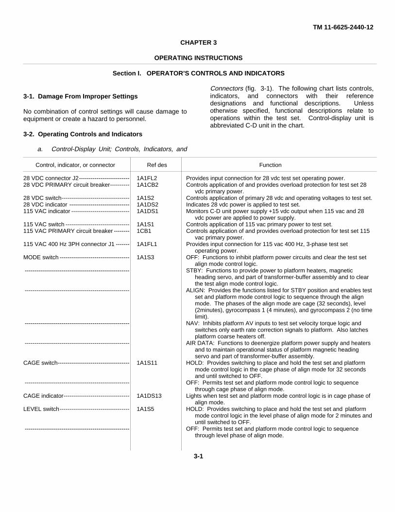
a. Control-Display Unit; Controls, Indicators, and
Connectors (fig. 3-1). The following chart lists controls,indicators, and connectors with their referencedesignations and functional descriptions. Unlessotherwise specified, functional descriptions relate tooperations within the test set. Control-display unit isabbreviated C-D unit in the chart.
Control, indicator, or connector Ref des Function
28 VDC connector J2-------------------------- 1A1FL2 Provides input connection for 28 vdc test set operating power.28 VDC PRIMARY circuit breaker---------- 1A1CB2 Controls application of and provides overload protection for test set 28
vdc primary power.28 VDC switch----------------------------------- 1A1S2 Controls application of primary 28 vdc and operating voltages to test set.28 VDC indicator ------------------------------- 1A1DS2 Indicates 28 vdc power is applied to test set.115 VAC indicator ------------------------------ 1A1DS1 Monitors C-D unit power supply +15 vdc output when 115 vac and 28
vdc power are applied to power supply.115 VAC switch --------------------------------- 1A1S1 Controls application of 115 vac primary power to test set.115 VAC PRIMARY circuit breaker -------- 1CB1 Controls application of and provides overload protection for test set 115
vac primary power.115 VAC 400 Hz 3PH connector J1 ------- 1A1FL1 Provides input connection for 115 vac 400 Hz, 3-phase test set
operating power.MODE switch ------------------------------------ 1A1S3 OFF: Functions to inhibit platform power circuits and clear the test set
align mode control logic.------------------------------------------------------ STBY: Functions to provide power to platform heaters, magnetic
heading servo, and part of transformer-buffer assembly and to clearthe test align mode control logic.
------------------------------------------------------ ALIGN: Provides the functions listed for STBY position and enables testset and platform mode control logic to sequence through the alignmode. The phases of the align mode are cage (32 seconds), level(2minutes), gyrocompass 1 (4 minutes), and gyrocompass 2 (no timelimit).
------------------------------------------------------ NAV: Inhibits platform AV inputs to test set velocity torque logic andswitches only earth rate correction signals to platform. Also latchesplatform coarse heaters off.
------------------------------------------------------ AIR DATA: Functions to deenergize platform power supply and heatersand to maintain operational status of platform magnetic headingservo and part of transformer-buffer assembly.
CAGE switch------------------------------------- 1A1S11 HOLD: Provides switching to place and hold the test set and platformmode control logic in the cage phase of align mode for 32 secondsand until switched to OFF.
------------------------------------------------------ OFF: Permits test set and platform mode control logic to sequencethrough cage phase of align mode.
CAGE indicator---------------------------------- 1A1DS13 Lights when test set and platform mode control logic is in cage phase ofalign mode.
LEVEL switch------------------------------------ 1A1S5 HOLD: Provides switching to place and hold the test set and platformmode control logic in the level phase of align mode for 2 minutes anduntil switched to OFF.
------------------------------------------------------ OFF: Permits test set and platform mode control logic to sequencethrough level phase of align mode.
3-1

TM 11 6625-2440-12
Control, indicator, or connector Ref des Function
LEVEL indicator--------------------------------- 1A1DS12 Lights when test set and platform mode control logic is in level phase ofalign mode.
GC1 switch --------------------------------------- 1A1S6 HOLD: Provides switching to place and hold the test set and platformmode control logic in the GC1 phase of align mode for 4 minutes anduntil switched to OFF.
------------------------------------------------------ OFF: Permits test set and platform mode control logic to sequencethrough GC1 phase of align mode.
GC1 indicator ------------------------------------ 1A1DS14 Lights when test set and platform mode control logic is in GC1 phase ofalign mode.
GC2 indicator ------------------------------------ 1A1DS15 Lights when test set and platform mode control logic is in GC2 phase ofalign mode.
COARSE HEATER indicator ---------------- 1A1DS11 Indicates platform coarse heaters are energized.SELF-TEST indicator -------------------------- 1A1DS3 Indicates test set is in self-test mode.PLATF PWR indicator ------------------------- 1A1DS10 Indicates 115 vac and 28 vdc are applied to platform.GSP TEST indicator --------------------------- 1A1DS4 Indicates test set is in platform test mode.X switch ------------------------------------------- 1A1S8 PLUS: Provides for manual slewing of platform stable element in a
positive direction about the X (pitch) axis.MINUS: Provides for manual slewing of platform stable element in a
negative direction about the X (pitch) axis.OFF: Inhibits manual slewing of platform stable element about the X
(pitch) axis.Y switch ------------------------------------------- 1A1S9 PLUS: Provides for manual slewing of platform stable element in a
positive direction about the Y (roll) axis.------------------------------------------------------ MINUS: Provides for manual slewing of platform stable element in a
negative direction about the Y (roll) axis.------------------------------------------------------ OFF: Inhibits manual slewing of platform stable element about the Y
(roll) axis.Z switch ------------------------------------------- 1A1S10 PLUS: Provides for manual slewing of stable element in a positive
direction about the Z (heading) axis.------------------------------------------------------ MINUS: Provides for manual slewing of platform stable element in a
negative direction about the Z (heading) axis.------------------------------------------------------ OFF: Inhibits manual slewing of platform stable element about the Z
(heading) axis.FAST-SLOW switch --------------------------- 1A1S12 Operates in series with C-D unit PLATFORM SLEW switches to provide
two-speed selection for platform stable element slewing.GB1-GB2 switch -------------------------------- 1A1S14 Sets velocity torque logic in C-D unit for gyro bias 1 or gyro bias 2
operation.PLATF RE CAGE switch --------------------- 1A1S7 Generates platform reset signal, causing platform mode logic in C-D unit
and platform to sequence through the cage phase and initiate thelevel phase of the align mode.
PLATFORM indicator-------------------------- 1A1DS6 Indicates a malfunction in platform power turn-on sequence logic.MONITOR indicator ---------------------------- 1A1DS7 Indicates a platform malfunction.OVERTEMP indicator ------------------------- 1A1DS5 Indicates overtemperature condition in platform.TEST SET indicator---------------------------- 1A1DS9 Indicates test set malfunction.MONITOR OVERRIDE switch--------------- 1A1S13 Overrides platform malfunction indicated by CD unit MONITOR indicator
and allows operation of platform.MAT HDG SERVO indicator ----------------- 1A1DS8 Indicates a platform magnet ic heading servo malfunction.READING SIMULATOR ---------------------- 1A1B1 Provides selection of a desired azimuth angle to which a platform stable
element will be driven, with respect to platform heading during thecage phase of align mode.
LAMP TEST switch----------------------------- 1A1S4 Energizes all indicator lamp circuits when pressed, as a test of theindicator lamps.
ELAPSED TIME meter ------------------------ 1A1M1 Indicates total time that CD unit has been in operation.Connector J3 ------------------------------------ 1A1J3 Provides power connection between CD unit and electronics unit.Connector J4 ------------------------------------ 1A1J4 Provides control signal connection between CD unit and electronics unit.BREATHER VALVE --------------------------- Provides two-way pressure equalization.
b. Electronics Unit; Controls, Indicators, andConnectors (fig. 3-2). The following chart lists controls,indicators, and connectors with their referencedesignations and functional descriptions. All controls and
indicators, except the LATITUDE switch, are located onthe front panel. The LATITUDE switch is located insidethe combination case at the rear of the unit (fig. 4-2).Control-display unit is abbreviated C-D unit in the chart.
3-2

TM 11-6625-2440-12
Figure 3-1. Control-display unit; controls, indicators, and connectors.
3-3

TM 11-6625-2440-12
Figure 3-2. Electronics unit; controls, indicators, and connectors.
3-4

TM 11-6625-2440-12
Control, indicator, or connector Ref des Function
TEST SET SCAN switch---------------------- 2A1S1 Used with SCAN SELECT switch to select functions (1 thru 17) withinthe test set for monitoring by ancillary test equipment.
SCAN SELECT switch ------------------------ 2A1S2 Operates with TEST SET SCAN and PLATFORM SCAN switches toselect functions within the test set or platform under test formonitoring by ancillary test equipment.
PLATFORM SCAN switch-------------------- 2A1S3 Used with SCAN SELECT switch to select functions (1 thru 17) withinthe platform under test for monitoring by ancillary test equipment.
SYNCHRO SELECT switch------------------ 2A1S4 PITCH 1/PITCH 2: Selects platform pitch synchro signals and routesthem to decade synchro bridge for angular measurement.
ROLL 1/ROLL 2: Selects platform roll synchro signals and routes themto decade synchro bridge for angular measurement.
TRUE HD: Selects azimuth signals from platform synchros and routesthem to decade synchro bridge for angular measurement.
MAG HD 1/2/3: With SIGNAL INPUT switch set to positions 1 through6, selects simulated azimuth signals from platform magnetic headingservos and routes them to decade synchro bridge for angularmeasurement.
OFF: Disconnects platform synchro signals from decade synchrobridge.
SIGNAL INPUT switch ------------------------ 2A1S5 OFF: No connection.Positions 1 through 6: Provides selection of six simulated magnetic
heading outputs to the platform.Position 8: Initiates plus ∆Vx and minus ∆Vy velocity torque logic self-
test.Position 9: Initiates minus ∆Vx and plus ∆Vy velocity torque logic self-
test.Positions 7 and 10 through 17: Not used.
LEVEL AXIS thumbwheel switches -------- 2A1S6 Used to select the local level axis earth rate correction frequency to beapplied to the platform stable element.
HEADING AXIS thumbwheel switches---- 2A1S7 Used to select the local heading axis earth rate correction frequency tobe applied to the platform stable element.
HIGH GAIN switch ----------------------------- 2A1S8 OPERATE: Routes platform Ax and Ay accelerometer signals torecorder channels 1 and 2 respectively.
ZERO REF: Shorts the input of the recorder high-gain channels toground.
PSD switch --------------------------------------- 2A1S9 OPERATE: Routes the platform azimuth synchro and decade synchrobridge outputs to recorder channels 5 and 6 respectively.
ZERO REF: Shorts the input of the recorder phase-sensitivedemodulator channels to ground.
LOW GAIN switch ------------------------------ 2AS10 OPERATE: Routes the platform ∆Vx and ∆Vy ramp voltages to recorderchannels 3 and 4 respectively.
------------------------------------------------------ ZERO REF: Shorts the inputs of the recorder low-gain channels.LOW GAIN connector J10 ------------------- 2A1J10 Provides output connection to recorder low-gain channel.PSD connector J9 ------------------------------ 2A1J9 Provides output connection to recorder phase-sensitive demodulator.HIGH GAIN connector J8 -------------------- 2A1J8 Provides output connection to recorder high-gain channel.115 VAC APH circuit breaker --------------- 2A1CB1 Controls application and provides overload protection for 115 vac, A-
phase power to platform.26 VAC circuit breaker ------------------------ 2A1CB4 Controls application and provides overload protection for 26 vac power
to platform azimuth, pitch, outer roll, and magnetic heading servosynchros.
SE HEAT circuit breaker---------------------- 2A1CB3 Controls application and provides overload protection for 115 vac, C-phase power to platform stable element heaters and referencetransformer.
AMB HEAT circuit breaker ------------------- 2A1CB2 Controls application and provides overload protection for 115 vac, C-phase power to platform ambient heaters, reference transformer,and blowers.
ELAPSED TIME meter ------------------------ 2A1M1 Indicates total time that electronics unit has been in operation.Connector J6 ------------------------------------ 2A1J6 Provides power and control signal output connect ion to platform and
provides platform test signal input connection to test set.Connector J7 ------------------------------------ 2A1J7 Provides platform test signal input to test set.COUNTER connector J1 --------------------- 2A1J1 Provides test output connection to counter.VM connector J2-------------------------------- 2A1J2 Provides test output connection to differential voltmeter.SYNC BRDG connector J3 ------------------ 2A1J3 Provides test output connection to decade synchro bridge.PH ANGLE VM connector J4---------------- 2A1J4 Provides test output connection to phase angle voltmeter.SCOPE connector J5-------------------------- 2A1J5 Provides test output connection to oscilloscope.
3-5
TM 11-6625-2440-12
Control, indicator, or connector Ref des Function
Connector J11----------------------------------- 2A1J11 Provides control signal connection between electronics unit and C-Dunit.
Connector J12----------------------------------- 2A1J12 Provides power connection between electronics unit and C-D unit.LATITUDE switch (internal) ------------------ 2A1S11 NORTH: Provides polarity of platform stable element heading axis earth
rate correction for proper operation in the northern hemisphere.SOUTH: Provides polarity of platform stable element heading axis earth
rate correction for proper operation in the southern hemisphere.Note. This switch is set during installation and need not be moved
unless the test set is moved across the equator. (See chapter 2.)BREATHER VALVE --------------------------------------------------- Provides two-way pressure equalization.
Section II. OPERATION UNDER USUAL CONDITIONS
3-3. General
The test set is operated normally to test and troubleshoota platform and to perform a self-test of the test set.Operation for performing test and troubleshootingprocedures on a platform are contained in themaintenance manual for the platform being tested. Toperform test procedures on a platform, it is necessary toset the LATITUDE CORRECTION thumbwheel switchesto compensate for the earth’s rotational velocity at thespecific latitude of the test site. Instructions andcalculations for inserting latitude corrections are detailedin paragraph 3-5. Test set self-test procedures areincluded in paragraph 3-6. Under normal conditions, self-test of the test set should be performed after installation,monthly when in continuous use, before each platformtest when used intermittently, or when the test setoperational status is questionable.
3-4. Operating Procedures
NOTEBefore performing any operating proce-dures, read and fully understand theinformation in paragraph 3-2.
a. Preliminary Control Settings. Verify thefollowing test set conditions or perform the necessaryoperations:
(1) Test set primary ac and dc power sourcesare off.
(2) Control-display unit 28 VDC and 115 VACswitches are set to OFF.
(3) Control-display unit 28 VDC PRIMARYand 115 VAC PRIMARY circuit breakers are set to OFF.
(4) Electronics unit 115 VAC APH, 26 VAC,SE HEAT, and AMB HEAT circuit breakers are set toOFF.
NOTEDisregard setting of LATITUDECORRECTION thumbwheel switches.
(5) All other control-display unit andelectronics unit switches are set to OFF or down position.
b. Power Application.(1) Turn on test set primary ac and dc power
sources.(2) Set control-display unit 28 VDC PRIMARY
and 115 VAC PRIMARY circuit breakers to ON.(3) Set electronics unit 115 VAC APH, 26
VAC, SE HEAT, and AMB HEAT circuit breakers to ON.(4) Set control-display unit 115 VAC switch to
ON.(5) Set control-display unit 28 VDC switch to
ON.(6) Verify that the 28 VDC, 115 VAC, and SELF
TEST indicators light and that the ELAPSED TIMEmeters on both units are functioning.
(7) Turn on ancillary test equipment.
NOTEAllow a 30-minute warmup for ancillarytest equipment.
c. Standby Condition.(1) Set control-display unit 28 VDC switch to
OFF.(2) Set control-display unit 115 VAC switch to
OFF.
NOTEMaintain test set in standby condition atall times except when moving test set toa new location.
3-6

TM 11-6625-2440-12d. Power Turnoff.
(1) Set controls to positions indicated in a (2)through (5) above.
(2) Turn off test set ac and dc power sources.
3-5. Latitude Earth Rate Correction
Each position of each of the LEVEL AXIS and HEADINGAXIS thumbwheel switches represents a specificfrequency. Any frequency required by the platform maybe obtained by selecting combinations of these switchsettings. A list of these specific frequencies and thethumbwheel switch settings required to obtain them isprovided in a below. The requirements and method formaking the computations necessary to determine thethumbwheel switch setting for the specific latitude of thetest site are given in b through d below.
a. Thumbwheel Switch Frequency Chart.
NOTEThe thumbwheel switches aredesignated (left to right) A through F foreach switch group.
LEVEL AXIS or HEADING FrequencyAXIS switch Setting (Hz)
A ---------------- 0 01 18.752 37.503 56.254 75.005 93.756 112.507 131.25
B ---------------- 0 01 2.343752 4.687503 7.031254 9.375005 11.718756 14.062507 16.40625
C ---------------- 0 010.292969
2 0.6859383 0.8789064 1.1718755 1.4648446 1.7578137 2.050782
D ---------------- 0 01 0.0366212 0.0732423 0.1098634 0.1464845 0.1831056 0.2197267 0.256347
LEVEL AXIS or HEADING FrequencyAXIS switch Setting (Hz)
E --------------------- 0 01 0.0045772 0.0091553 0.0137334 0.0183115 0.0228886 0.0274667 0.032043
F --------------------- 0 01 0.000572 0.001143 0.001714 0.002285 0.002856 0.003427 0.00399
b. Level Axis Latitude Correction. The level axislatitude correction frequency (F) for any earth-latitudeposition may be determined by completing the following:
(1) Obtain the earth-latitude position (λ) of thetest site from the local cognizant authority.
(2) Determine the cos λ to the nearest tenthof a minute using sine and cosine interpolation describedin d below.
(3) Calculate the frequency by substituting thevalue determined in (2) above for cos λ in the equation F= (80. 28668 cos λ) Hz. Record the calculatedfrequency.
(4) Using the thumbwheel switch frequencychart in a above, determine the correct LEVEL AXISthumbwheel switch settings for the calculated frequencyand set thumbwheel switches accordingly. Thesequence for setting the thumbwheel switches is asfollows:
(a) Select highest A-switch setting whichrepresents but does not exceed the calculated frequency.
(b) Subtract frequency represented by Aswitch setting from calculated frequency.
(c) Select highest B-switch setting whichrepresents but does not exceed the frequency remaindercalculated in (b) above.
(d) Subtract frequency represented by B-switch setting from frequency represented by A-switchsetting.
(e) Select highest C-switch setting whichrepresents but does not exceed the frequency remaindercalculated in (d) above.
(f) Repeat (d) and (e) above for each ofthe remaining thumbwheel switches in order, left to right.
Example: Assuming the test site latitude (λ) to be34°14.1"; the formula becomes F = (80.28668 cos34°14.1”) Hz.
3-7

TM 11-6625-2440-12Substituting the value of the cosine function (ref d below);the formula becomes F = (80. 28668 X 0.8267398) Hz orF = 66. 376194 Hz.From thumbwheel switch frequency chart (a above),select highest A-switch setting which represents but doesnot exceed the frequency 66. 376194 Hz.A-switch setting is 3, representing a frequency of 56. 25Hz.Subtract 56. 25 from 66. 376194 Hz. Remainder is10.126194.Select highest B-switch setting which represents butdoes not exceed the frequency remainder from A-switchsetting.B-switch setting is 4, representing 9. 375 Hz.Subtract 9. 375 from 10. 126194 Hz. Remainder is0.751194.Select highest C-switch setting which represents butdoes not exceed the frequency remainder from B-switchsetting.C-switch setting is 2, representing 0. 585938 Hz.Subtract 0. 585938 from 0. 751194 Hz. Remainder is0.165256.Select highest D-switch setting which represents butdoes not exceed the frequency remainder from C-switchsetting.D-switch setting is 4, representing 0. 146484 Hz.Subtract 0. 146484 from 0. 165256 Hz. Remainder is0.018772.Select highest E-switch setting which represents butdoes not exceed the frequency remainder from D-switchsetting.E-switch setting is 4, representing 0. 018311 Hz.Subtract 0. 018311 Hz from 0. 018772. Remainder is0.000461.Select highest F-switch setting which represents butdoes not exceed the frequency remainder from E-switchsetting.F-switch setting is 0.The complete LEVEL AXIS thumbwheel switch settingshould be 342440, indicating the assumed latitude of34°14.1".
c. Heading Axis Latitude Correction. The headingaxis latitude correction frequency (F) for any earth-latitude position may be determined by completing thefollowing:
(1) Obtain the earth-latitude position (λ) of thetest site from the local cognizant authority.
(2) Determine the sin λ to the nearest tenth ofa minute as described in d below.
(3) Calculate the frequency by substituting thevalue for sin λ in the equation F = (40.14323 sin λ) Hz.Record the calculated frequency.
(4) Using the thumbwheel switch frequencychart in a above, determine the correct HEADING AXISthumbwheel switch setting for the calculated frequencyand set thumbwheel switches accordingly. Thesequence and procedure for setting the thumbwheelswitches is the same as in b (4) above.
d. Sine and Cosine Interpolation to 0.1 Minute.To find the sine or cosine of latitude to the nearest 0. 1minute, use a natural trigonometric functions table (TM11-684) and proceed as follows:
(1) In natural trigonometric functions table,find and record sin or cos of given latitude to nearestlower minute and nearest higher minute.
(2) Subtract lower value from higher value.(3) Multiply difference by number of tenths of
minutes to which latitude is given.(4) Add product to lower of sin value or
subtract product from higher cos value.
Example:(a) Find the sin of latitude to nearest 0.1 minute.Given latitude = 18°4.2'Sin 18°4' = 0.31012.Sin 18°5' = 0.31040.(b) Subtract lower value from higher value:sin 185°5’--sin 18°4' = 0.31040--0.31012= 0. 00028.(c) Multiply difference by desired tenths of a
minute:0.00028 X 0.2 = 0.000056.(d) Add product to lower sin value:0.31012 + 0.000056 = 0.310176.
NOTEWhen cos of latitude to nearest0.1minute is being determined, subtractproduct from higher cos value.
3-6. Self-Test Procedures
Operation of the test set can be checked by performingpreliminary operations (a below) and procedures in theself-test chart (c below). A stopwatch is required forperforming tests in the chart. Explanations of self-testchart column headings are listed in b below.
3-8

TM 11-6625-2440-12
a. Preliminary Operations for Self-Test. Performthe following:
(1) Verify the initial conditions and controlsettings as indicated in paragraph 3-4a.
(2) Verify that test set and ancillary testequipment are connected as shown in figure 2-2 (bridgeand recorder not used).
(3) Turn on test set primary ac and dc powersources.
(4) Turn on ancillary test equipment.NOTE
Allow a 30-minute warmup for ancillarytest equipment.
b. Self-Test Chart Column Explanations. Anexplanation of the information in each of the self-testchart columns is as follows:
(1) Sequence No. column. Lists thesequence in which the tests must be performed. Thesequence number also serves as a cross-reference toprocedures in the troubleshooting chart (para 4-16).
(2) Item column. Specifies the circuit orfunction being tested.
(3) Procedure column. Specifies the unit andlists all action to be performed relating to specificoperations, observations, and records. The normal
indications or results of these actions are included in thiscolumn. The following abbreviations are used in thiscolumn:
C-D (control-display unit)EU (electronics unit)DVM (voltmeter)Scope (oscilloscope)PAV (phase angle voltmenter)(4) Reference column. Lists troubleshooting
paragraph relating to abnormal indications resulting fromthe actions in the procedure column.
NOTEThe LATITUDE switch, located at therear of the electronics unit chassis, is setto NORTH or SOUTH during installationof the test set (para 2-5). This switch isset in accordance with the hemisphere inwhich the test site is located. In theprocedures in the self-test chart below,indications affected by the switch settingare given for both NORTH and SOUTHpositions of the switch. The switchsetting should not be changed whenperforming the self-test procedures, andthe indication that is not applicableshould be disregarded.
c. Self-Test Chart.
Seq Item Procedure ReferenceNo.
1 C-D blower .......................... a. Set C-D 115 VAC PRIMARY and 28 VDC Paragraphs 4-15 and 4-16.PRIMARY circuit breakers to ON.
b. Set C-D 115 VAC switch to ON. C-D bloweroperates (audible )
2 Primary power..................... a. Set EU 115 VAC APH, 26 VAC, SE HEAT, and Paragraphs 4-15 and 4-16.AMB HEAT circuit breakers to ON
b. Set EU SCAN SELECT switch to AC VOLTSc. Set EU PLATFORM SCAN switch to positions,
indicated below, and observe PAV andcounter kor voltages and frequencies listed.
Switch Frequencyposition Voltage (Hz)
1 115 (± 11.5)/0° 400 (± 20)2 115 (± 11.5)/240° 400 (± 20)3 115 (± 11.5)/120° 400 (± 20)
3 26v, 400-Hz circuitry ........... Set EU PLATFORM SCAN switch to 4, and observe Paragraphs 4-15 and 4-16.PAV for indication of 26 (±+2) V/iO and counterfor an indication 400 (± 20) HZ.
4 Dc voltages ......................... a. Set EU PLATFORM SCAN switch to OFF. Paragraphs 4-15 and 4-16.b Set C-D 28 VDC switch to ON.c. Observe the following:
(1) C-D 28 VDC, 115 VAC, and SELF-TEST in-dicators light.(2) C-D TEST SET indicator does not light.(3) C-D anti EU ELAPSED TIME meters run.
5 Power supply voltages ........ a. Set EU SCAN SELECT switch to DISCRETES Paragraphs 4-15 and 4-16.b. Set EU TEST SET SCAN switch to positions
indicated below, and observe scope and DVMfor voltages listed.Switch position Voltage1 + 5 (± 0.5)2 + 15(± 1.00)3 - 15 (± 1.0)
Change 1 3-9

TM 11-6625-2440-12
Seq Item Procedure ReferenceNo.
6 Indicators ............................ a. Set EU TEST SET SCAN switch to OFF. Paragraphs 4-15 and 4-16.b. Press and hold C-D LAMP TEST switch,and observe that all C-D indicators light.
7 Indicators ............................ Release C-D LAMP TEST switch, and Paragraphs 4-15 and 4-16.Observe that all indicators except28 VDC, 115 VAC, and SELF TEST goout.
8 Lamp drivers ....................... Set EU TEST SET SCAN switch to 16, and Paragraphs 4-15 and 4-16.observe that PLATFORM. MONITOR,OVERTEMP, and MAG HDC SERVOindicators light.
9 Lamp drivers ....................... Set EU TEST SET SCAN switch to OFF, and Paragraphs 4-15 and 4-16.observe that PLATFORM, MONITOR,OVERTEMP, and MAG HDG SERVOindicators go out.
NOTEWhen the EU TEST SET SCAN switch is, setto 16. the PLATFORM, MONITOR,OVERTEMP and MAG HDG SERVOindicators will light. Disregard the lighting ofthese indicators at this switch setting for theremainder of test procedure.
10 Clock generator .................. Set EU TEST SET SCAN to 17, and observe Paragraphs 4-15 and 4-16.Scope and DVM for an indication of+ 28 (± 1.4) V.
11 Clock generator .................. a. Set EU SCAN SELECT switch to CHAN Z Paragraphs 4-15 and 4-16.b. Set EU TEST SET SCAN switch to
positions listed below, and observecounter and scope for frequencies andwaveform listed.
Switch Freq. Waveformposition (Hz) (fig. 3-3)
7 300 (± 1) A8 300 (± 1) A9 150 (± 1) B
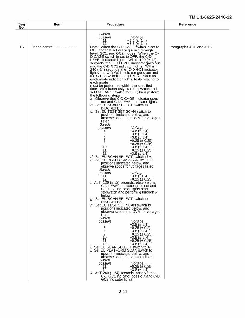
10 2.4 k (+ 1) C12 Mode control ....................... Set EU TEST SET SCAN switch to positions Paragraphs 4-15 and 4-16.
indicated below, and observe counterfor frequencies listed.
Switch Frequencyposition (Hz)
11 4.68(± 0.1)12 2.34 (±0.1)
13 Mode control ....................... a. Set C-D CAGE switch to HOLD. Paragraphs 4-15 and 4-16.b. Set C-D MODE switch to ALIGN, CAGE,
PLATFORM, MONITOR, OVERTEMP,and MAG HDG SERVO indicators light.
14 Mode control ....................... a. Set EU SCAN SELECT switch to Paragraphs 4-15 and 4-16.DISCRETES.
b. Set EU TEST SET SCAM switch positionindicated below, and observe scopeand DVM for voltages listed
Switchpositions Voltage
4 +0.25 (± 0.25)5 +0.25 (± 0.25)6 +3.8 (± 1.4)8 +0.25(± 0.25)9 +0.25 (± 0.25)
10 +3.8 (± 1.4)11 +3.8 (± 1.4)12 +0025 (± 0.25)
15 Mode control ....................... a. Set EU SCAN SELECT switch to A. Paragraphs 4-15 and 4-16.b. Set EU PLATFORM SCAN switch to
positions indicated below, and observescope for voltages listed.
Change 1 3-10
TM 1 1-6625-2440-12
Seq Item Procedure ReferenceNo.
Switchposition Voltage
11 +3.8 (± 1.4)12 +3.8 (± 1.4)
16 Mode control ....................... Note. When the C-D CAGE switch is set to Paragraphs 4-15 and 4-16OFF, the test set will sequence throughlevel, GC1, and GC2 modes. When the C-D CAGE switch In set to OFF, the C-DLEVEL indicator lights. Within 120 ( ± 12)seconds, the C-D LEVEL indicator goes outand the C-D GC1 indicator lights. Within240 (-24) seconds after C-D GC1 indicatorlights, the C-D GC1 indicator goes out andthe C-D GC2 indicator lights. As soon aseach mode indicator lights, tests relating toeach modemust be performed within the specifiedtime. Simultaneously start stopwatch andset C-D CAGE switch to OFF; then performthe following stepsa. Observe that C-D CAGE indicator goes
out and C-D LEVEL indicator lights.b. Set EU SCAN SELECT switch to
DISCRETES.c. Set EU TEST SET SCAN switch to
positions indicated below, andobserve scope and DVM for voltageslisted.
Switchposition Voltage
4 +3.8 (± 1.4)5 +3.8 (± 1.4)6 +3.8 (± 1.4)8 +0.25 (± 0.25)9 +0.25 (± 0.25)
10 +3.8 (± 1.4)11 +0.25 (± 0.25)12 +3.8 (± 1.4)
d. Set EU SCAN SELECT switch to A.e. Set EU PLATFORM SCAN switch to
positions indicated below, andobserve scope for voltages listed.
Switchposition Voltage
11 +3.8 (±1. 4)12 +0.25 (± 0.25)
f. At T=120 (± 12) seconds, observe thatC-D LEVEL indicator goes out andC-D GC1 indicator lights startstopwatch and perform g through kbelow.
g. Set EU SCAN SELECT switch toDISCRETES.
h. Set EU TEST SET SCAN switch topositions indicated below, andobserve scope and DVM for voltageslisted.
Switchposition Voltage
4 +3.8 (± 1.4)5 +0.26 (± 0.2)8 +3.8 (±:1.4)9 +0.25 (± 0.25)
10 +3.8 (± 1. 4)11 +0.25 (± 0.25)12 +3.8 (± 1.4)
i. Set EU SCAN SELECT switch to Aj. Set EU PLATFORM SCAN switch to
positions indicated below, andobserve scope for voltages listed.
Switchposition Voltage
11 +0.25 (± 0.25)12 +3.8 (± 1.4)
k. At T-240 (± 24) seconds, observe thatC-D GC1 indicator goes out and C-DGC2 indicator lights.
3-11
TM 11-6625-2440-12
Seq Item Procedure ReferenceNo.
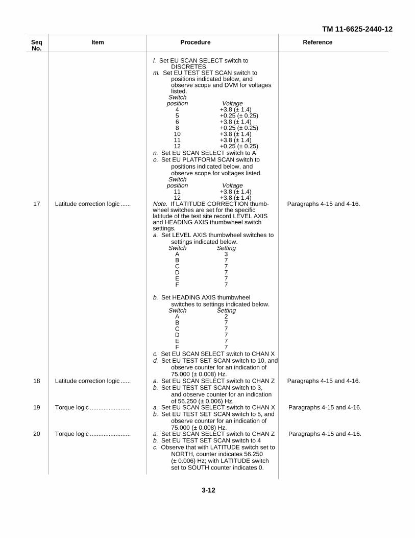
l. Set EU SCAN SELECT switch toDISCRETES.
m. Set EU TEST SET SCAN switch topositions indicated below, andobserve scope and DVM for voltageslisted.
Switchposition Voltage
4 +3.8 (± 1.4)5 +0.25 (± 0.25)6 +3.8 (± 1.4)8 +0.25 (± 0.25)
10 +3.8 (± 1.4)11 +3.8 (± 1.4)12 +0.25 (± 0.25)
n. Set EU SCAN SELECT switch to Ao. Set EU PLATFORM SCAN switch to
positions indicated below, andobserve scope for voltages listed.
Switchposition Voltage
11 +3.8 (± 1.4)12 +3.8 (± 1.4)
17 Latitude correction logic ...... Note. If LATITUDE CORRECTION thumb- Paragraphs 4-15 and 4-16.wheel switches are set for the specificlatitude of the test site record LEVEL AXISand HEADING AXIS thumbwheel switchsettings.a. Set LEVEL AXIS thumbwheel switches to
settings indicated below.Switch Setting
A 3B 7C 7D 7E 7F 7
b. Set HEADING AXIS thumbwheelswitches to settings indicated below.
Switch SettingA 2B 7C 7D 7E 7F 7
c. Set EU SCAN SELECT switch to CHAN Xd. Set EU TEST SET SCAN switch to 10, and
observe counter for an indication of75.000 (± 0.008) Hz.
18 Latitude correction logic ...... a. Set EU SCAN SELECT switch to CHAN Z Paragraphs 4-15 and 4-16.b. Set EU TEST SET SCAN switch to 3,
and observe counter for an indicationof 56.250 (± 0.006) Hz.
19 Torque logic ........................ a. Set EU SCAN SELECT switch to CHAN X Paragraphs 4-15 and 4-16.b. Set EU TEST SET SCAN switch to 5, and
observe counter for an indication of75.000 (± 0.008) Hz.
20 Torque logic ........................ a. Set EU SCAN SELECT switch to CHAN Z Paragraphs 4-15 and 4-16.b. Set EU TEST SET SCAN switch to 4c. Observe that with LATITUDE switch set to
NORTH, counter indicates 56.250(± 0.006) Hz; with LATITUDE switchset to SOUTH counter indicates 0.
3-12

TM 11-6625-244012
Seq Item Procedure ReferenceNo.21 Torque logic a. Set EU TEST SET SCAN switch to 5 Paragraphs 4-15 and 4-16.
b. Observe that with LATITUDE switch setto NORTH, counter indicates 0; withLATITUDE switch set to SOUTH,counter indicates 56.250 (± 0.006) Hz.
22 Torque logic ........................ a. Set C-D GYRO BIAS switch to GB1 Paragraphs 4-15 and 4-16.b. Set EU SCAN SELECT switch to CHAN Y,
and observe counter for an indicationof 75.000 (± 0.008) Hz.
23 Torque logic ........................ a. Set EU SCAN SELECT switch to CHAN X Paragraphs 4-15 and 4-16.b. Set EU TEST SET SCAN switch to 7, and
observe counter for an indication of112.5 (±1.0) Hz.
24 Torque logic ........................ Set EU SCAN SELECT switch to CHAN Y, Paragraphs 4-15 and 4-16.and observe counter for an indicationof 150 (± 1) Hz.
25 Torque logic ........................ a. Set EU SCAN SELECT switch to CHAN Z Paragraphs 4-15 and 4-16.b. Set EU TEST SET SCAN switch to 6.c. Observe that with LATITUDE switch set to
NORTH, counter indicates 122 (± 1) Hz;with LATITUDE switch set to SOUTH,counter indicates 172 (± 1) Hz.
26 Torque logic ........................ a. Set C-D GYRO BIAS switch to GB2 Paragraphs 4-15 and 4-16.b. Set EU SCAN SELECT switch to CHAN X.c. Set EU TEST SET SCAN switch to 7, and
observe counter for an indication of150 (±1) Hz.
27 Torque logic ........................ a. Set EU SCAN SELECT switch to CHAN Y, Paragraphs 4-15 and 4-16.And observe counter for an indicationof 112.5 (± 1.0) Hz.
28 Torque logic ........................ a. Set EU SCAN SELECT switch to CHAN Z Paragraphs 4-15 and 4-16.b. Set EU TEST SET SCAN switch to 6c. Observe that the LATITUDE switch set to
NORTH, counter indicates 122 (± 1)Hz; with LATITUDE switch set toSOUTH, counter indicates 172 (±1) Hz.
29 Torque logic ........................ a. Set EU SCAN SELECT switch to B Paragraphs 4-15 and 4-16.b. Set EU PLATFORM SCAN switch to 3c. Set C-D PLATFORM SLEW X switch to
PLUS and observe scope for an indica-tion of +0.25 (± 0.25) V.
30 Torque logic ........................ Set C-D PLATFORM SLEW X switch to MINUS, Paragraphs 4-15 and 4-16.and observe scope for an indication of+3.8 (± 1.4) V.
31 Torque logic ........................ a. Set EU PLATFORM SCAN switch to 4 Paragraphs 4-15 and 4-16.b. Set C-D PLATFORM SLEW Y switch to
PLUS and observe scope for an indica-tion of ±:0.25 (± 0.25) V.
32 Torque logic ........................ Set C-D PLATFORM SLEW Y switch to Paragraphs 4-15 and 4-16.MINUS, and observe scope for anindication of ± 3. 8 (±:1.4) V.
33 Torque logic ........................ a. Set EU PLATFORM SCAN switch to 5 Paragraphs 4-15 and 4-16.b. Set C-D PLATFORM SLEW Z switch to
PLUS, and observe scope for anindication of +0. 25 (:0. 25) V.
34 Torque logic ........................ Set C-D PLATFORM SLEW Z switch to Paragraphs 4-15 and 4-16.To MINUS, and observe scope for anindication of +3. 8 (*1. 4) V.
35 ∆ V self-test......................... a. Set EU SIGNAL INPUT switch to 8 Paragraphs 4-15 and 4-16.b. Set EU SCAN SELECT switch to CHAN Xc. Set EU TEST SET SCAN switch to 1d. Observe counter for an indication of 1.0
(± 0.5) Hz and scope for waveform D,figure 3-3.
36 ∆ V self-test......................... a. Set EU SCAN SELECT switch to CHAN Y Paragraph 4-15 and 4-16.b. Observe counter for an indication of 1.0
(± 0.5) Hz and scope for waveform D,figure 3-3.
3-13

TM 11-6625-2440-12
Seq Item Procedure ReferenceNo.37 ∆ V self-test a. Set EU SIGNAL INPUT switch to 9 Paragraphs 4-15 and 4-16.
b. Set EU TEST SET SCAN switch to 2c. Observe counter for an indication of 1.0
(± 0.5) Hz and scope for waveform D,figure 3-3.
38 ∆ V self-test......................... a. Set EU SCAN SELECT switch to CHAN X Paragraphs 4-15 and 4-16.b. Observe counter for an indication of 1.0
(± 0.5) Hz and scope for waveform D,figure 3-3.
39 ∆ V self-test......................... Set EU TEST SET SCAN switch to 3, and Paragraphs 4-15 and 4-16.Observe scope for waveform E,figure 3-3.
40 ∆ V self-test......................... Set EU SCAN SELECT switch to CHAN Y, Paragraphs 4-15 and 4-16.and observe scope for waveform E,figure 3-3.
41 ∆ V self-test......................... a. Set EU SIGNAL INPUT switch to 8 Paragraphs 4-15 and 4-16.b. Set EU TEST SET SCAN switch to 4, and
observe scope for waveform E,figure 3-3.
42 ∆ V self-test......................... Set EU SCAN SELECT switch to CHAN X, Paragraphs 4-15 and 4-16.and observe scope for waveform E,figure 3-3.
43 ∆ V self-test......................... a. Set EU SCAN SELECT switch to Z Paragraphs 4-15 and 4-16.b. Set EU TEST SET SCAN switch to 1, and
observe scope for waveform F, figure3-3.
44 ∆ V self-test......................... a. Set EU SIGNAL INPUT switch to 9 Paragraphs 4-15 and 4-16.b. Set EU TEST SET SCAN switch to 2, and
observe scope for waveform F, figure3-3.
45 ∆ V self-test......................... a. Set C-D GYRO BIAS switch to GB1 Paragraphs 4-15 and 4-16.b. Set EU TEST SET SCAN switch to 1, and
observe scope for waveform F, figure3-3.
46 ∆ V self-test......................... a. Set EU SIGNAL INPUT switch to 8 Paragraphs 4-15 and 4-16.b. Set EU TEST SET SCAN switch to 2, and
observe scope for waveform F, figure3-3.
Note. Procedures In sequence numbers 47through 52 must be performed with counterset to at least 100-second gate.
47 Velocity-torque logic ........... a. Set EU SCAN SELECT switch to CHAN X Paragraphs 4-15 and 4-16.b. Set EU TEST SET SCAN switch to 7, and
observe that counter indicates between113.25 and 114.75 Hz.
48 Velocity-torque logic ........... Set EU SIGNAL INPUT switch to 9, and Paragraphs 4-15 and 4-16.observe that counter indicates between110.25 and 111.75 Hz.
49 Velocity-torque logic ........... a. Set C-D GYRO BIAS switch to GB2 Paragraphs 4-15 and 4-16.b. Set EU SCAN SELECT switch to Y, and
observe that counter indicates between110.25 and 111.75 Hz.
50 Velocity-torque logic ........... Set EU SIGNAL INPUT switch to 8, and Paragraphs 4-15 and -16.observe that counter indicates between113.25 and 114.75 Hz.
51 Velocity-torque logic ........... a. Set EU SCAN SELECT switch to CHAN Z Paragraphs 4-15 and 4-16.b. Set EU TEST SET SCAN switch to 6c. Observe that with LATITUDE switch set to
NORTH, counter indicates between37.88 and 93.88 Hz; with LATITUDEswitch set to SOUTH, counter indicatesbetween 54.12 and 150.12 Hz.
52 Velocity-torque logic ........... a. Set EU SIGNAL INPUT switch to 9 Paragraphs 4-15 and 4-16.b. Observe that with LATITUDE switch set to
NORTH, counter indicates between149.88 and 205.88 Hz; with LATITUDEswitch set to SOUTH, counter indicatesbetween 206.12 and 262.12 Hz.
53 Mode control ....................... Set C-D GC1 switch to HOLD, and observe Paragraphs 4-15 and 4-16.that GC2 indicator goes out and GC1indicator lights.
54 Divide-by-5 logic ................. Set EU TEST SET SCAN switch to 3, and Paragraphs 4-15 and 4-16.observe counter for an indication of11.25 (± 1) Hz.
TM 11-6625-2440-123-14
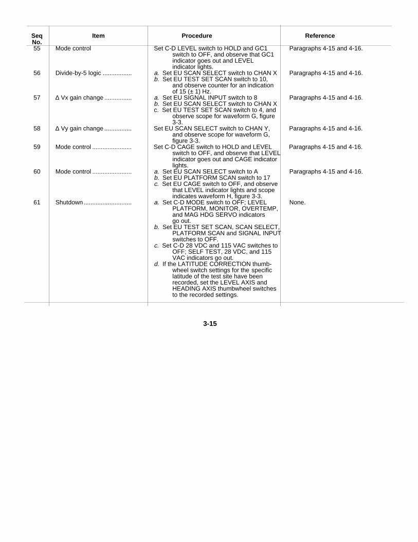
Seq Item Procedure ReferenceNo.55 Mode control Set C-D LEVEL switch to HOLD and GC1 Paragraphs 4-15 and 4-16.
switch to OFF, and observe that GC1indicator goes out and LEVELindicator lights.
56 Divide-by-5 logic ................. a. Set EU SCAN SELECT switch to CHAN X Paragraphs 4-15 and 4-16.b. Set EU TEST SET SCAN switch to 10,
and observe counter for an indicationof 15 (± 1) Hz.
57 ∆ Vx gain change ................ a. Set EU SIGNAL INPUT switch to 8 Paragraphs 4-15 and 4-16.b. Set EU SCAN SELECT switch to CHAN Xc. Set EU TEST SET SCAN switch to 4, and
observe scope for waveform G, figure3-3.
58 ∆ Vy gain change ................ Set EU SCAN SELECT switch to CHAN Y, Paragraphs 4-15 and 4-16.and observe scope for waveform G,figure 3-3.
59 Mode control ....................... Set C-D CAGE switch to HOLD and LEVEL Paragraphs 4-15 and 4-16.switch to OFF, and observe that LEVELindicator goes out and CAGE indicatorlights.
60 Mode control ....................... a. Set EU SCAN SELECT switch to A Paragraphs 4-15 and 4-16.b. Set EU PLATFORM SCAN switch to 17c. Set EU CAGE switch to OFF, and observe
that LEVEL indicator lights and scopeindicates waveform H, figure 3-3.
61 Shutdown............................ a. Set C-D MODE switch to OFF; LEVEL None.PLATFORM, MONITOR, OVERTEMP,and MAG HDG SERVO indicatorsgo out.
b. Set EU TEST SET SCAN, SCAN SELECT,PLATFORM SCAN and SIGNAL INPUTswitches to OFF.
c. Set C-D 28 VDC and 115 VAC switches toOFF; SELF TEST, 28 VDC, and 115VAC indicators go out.
d. If the LATITUDE CORRECTION thumb-wheel switch settings for the specificlatitude of the test site have beenrecorded, set the LEVEL AXIS andHEADING AXIS thumbwheel switchesto the recorded settings.
3-15

TM 11-6625-2440-12
H. MODE CONTROL DELAY PULSE
NOTES:1. ALL WAVEFORM AMPLITUDES VARY BETWEEN +.25(± .25)V AND + 3. 8(± 1. 4)V.2. EACH .37 SEC AREA CONTAINS 112 PULSES OCCURRING AT A 300Hz RATE.
EL6625-2440-12-12Figure 3-3. Test and troubleshooting waveforms.
3-16

TM 11-6625-2440-12
Section III. OPERATION UNDER UNUSUAL CONDITIONS
3-7. Operation at Temperature ExtremesTemperatures affecting operation of the test set includeboth the operating temperature extremes and thenonoperating ambient temperature extremes. The chartbelow lists the extremes for operation and exposure ofthe test set without degradation in specifiedperformance.
Nonoperating Operatingtemperature temperatures
Low maximum ........................ 32’F -65FHigh maximum ...................... 120’F 155*F
3-8. Operation in Tropical ClimatesA moisture and fungus proof (MFP) coating inaccordance with MILV-173 is applied as specified in MIL-T-152 to equipment, assemblies, and parts which havebeen cleaned prior to coating, to remove suchcontaminants as lubricating oils, mold release agents,sand, corrosion products, solder fluxes, fingerprints, anddust. The printed circuit boards have received aconformal coating per MILI-46058, and do not require theMFP coating at any time.
3-17

TM 11-6625-2440-12CHAPTER 4
ORGANIZANIZATIONAL MAINTENANCE
Section I. GENERAL
4-1. Scope of Organizational MaintenanceThe maintenance duties assigned to the operatorof the test set are listed below with a reference tothe paragraphs covering the specific maintenancefunction.a. Preventive maintenance checks and services(paras 4-3 through 4-12)b. Cleaning (para 4-13)c. Touchup painting instructions (para 4-14)d. Troubleshooting (paras 4-15 and 4-16)e. Removal and replacement (paras 4-17through 4-21)
4-2. Test Equipment, Tools, and MaterialsRequireda. Test Equipment. Test equipment necessaryfor organizational maintenance is listed in the followingchart:
Test equipment Federal stock No.Counter, Electronic Digital Readout 6625-911-6368AN/USM-2007( ).Voltmeter, Fluge 887A.Oscilloscope AN/USM-281 (w/Plug- 6625-053-2112ins PL-1186/USM-281 andPL-1187/USM-281).Voltmeter, Phase Angle ME-223----- 6625-810-3917Stopwatch, Monte Carlo 1002
b. Tools. Tools required for organizationalmaintenance are included in standard issue Tool KitsTK-101/G and TK-105/G.
c. Materials. The following chart lists thematerials necessary for organizational maintenance:
Material Federal stock No.Fine sandpaper No. 000..................... 5350-235-0124Clean, dry, lint free cloth .................... 8305-267-3015Soft bristle brush ................................ 8020-260-1306Cleaning compound (trichloroethane).Paint ................................................... 8010-817-1213
Section II. PREVENTIVE MAINTENANCE CHECKS AND SERVICES
4-3. Preventive MaintenancePreventive maintenance is the systematic care,servicing, and inspection of equipment to prevent theoccurrence of trouble, to reduce downtime, and to insurethat the equipment is serviceable.
a. Systematic Care. The procedures given inparagraphs 4-6 through 4-14 cover routine systematiccare and cleaning essential for proper upkeep andoperation of the equipment.
b. Preventive Maintenance Checks and Services.The preventive maintenance checks and services chartsoutline functions to be performed at specific intervals.These checks and services are to maintain electronicequipment in a combat serviceable condition; that is, ingood general (physical) condition and in good operatingcondition. To assist operators in maintaining combat
serviceability, the charts indicate what to check, how toperform the check and what action to take to correct afaulty indication. The Reference column lists theillustration, paragraph, or other manual that containsdetailed repair or replacement instructions. If the defectcannot be remedied by performing the corrective actionindicated, a higher category of maintenance is required.
4-4. Preventive Maintenance Checks and ServicesPeriodsPreventive maintenance checks and services on the testset are required daily, weekly, monthly, and quarterly.
a. Paragraph 4-6 specifies checks and servicesthat must be accomplished daily.
4-1

TM 11-6625-2440-12
b. Paragraphs 4-7 through 4-12 specifyadditional checks and services that must be performedon a weekly, monthly, and quarterly basis, respectively.
4-5. Daily Preventive Maintenance Checksand ServicesDaily Preventive maintenance includes checks andservices to be performed on external surfaces anddevices.
4-6. Daily Preventive Maintenance Checks and Services Chart
Seq.no. Item Procedure Reference
1 Completeness Check that all equipment is present Paragraph 1-6.2 Exterior surfaces Remove dirt and moisture from exposed surfaces Paragraph 4-13.
of cases, front panels, interconnecting plugs,and cables.
3 Indicator lenses Check for cracks and clips; replace lenses as necessary. Paragraph 4-20.4 Control knobs Check that control knobs are unbroken and are Paragraph 4-20.
tightly installed, but not binding against panel.Tighten loose knobs, adjust and retighten bindingknobs, replace broken knobs.
5 Switches Check that switches work smoothly and that no excessive None.looseness exists. If switch movement is faulty but doesnot downgrade the tests, repair if feasible or leave as is;otherwise refer switch repair to higher level of maintenance.
4-7.Weekly Preventive Maintenance Checks andServices
Weekly preventive maintenance includes checks and
services to be performed on metal surfaces, connectors,and cables. These checks and services are in additionto daily maintenance.
4-8. Weekly Preventive Maintenance Checks and Services Chart
Seq.no. Item Procedure Reference
1. Metal surfaces Inspect metal surfaces for rust or corrosion. Clean and touch Paragraph 4-14.up paint as required.
2. Front panel connectors Check control panel connectors for bent or damaged pins, None.Refer damaged connectors to higher level of maintenance.
3. Cables and cable Check cables for cracked or frayed insulation, broken wires, None.Connectors damaged connector. Refer damaged cable to higher level
of maintenance.
4-9. Monthly Preventive Maintenance Checks andServicesMonthly preventive maintenance checks services
checks and services check the test set electronics.These are in addition to daily and weekly maintenance.
4-10. Monthly Preventive Maintenance Checks and Services Chart
Seq.no. Item Procedure Reference
1 Test set........ .................... Perform test set self-test............................................................ Paragraph 3-6c.
4-11. Quarterly Preventive Maintenance Checksand ServicesQuarterly preventive maintenance includes checksand
sevices to be performed on software and spare parts.These checks and services are in addition to daily,weekly, and monthly maintenance.
4-2

TM 11-6625-2440-124-12. Quarterly Preventive Maintenance Checks and Services Chart
Seq Symptom Probable Cause Corrective actionNo.1 Publications ...................................... Check that all publications are complete, DA Pam 310-4.
serviceable, and current.2 Modifications..................................... Check to see if new applicable MWO’s DA Pam 310-7
have been published.All Urgent MWO’s must be applied imme-diately. Normal MWO’s must be scheduled.
3 Spare parts ....................................... Check all spare parts for general condition TM 11-6625-2440-20P.and method of storage. There should beno over-stock and shortages must be onrequisition.
4-13. CleaningWARNING
The fumes of trichloroethane are toxic.Provide thorough ventilation whenever used;DO NOT use near an open flame.Trichloroethane is not flammable, butexposure of the fumes to an open flameconverts the fumes to highly toxic, dangerousgases.
CAUTIONDo not use trichloroethane on any painted or silk-screened surface of the test set. Clean the front paneland control knobs with a soft, clean cloth. If dirt isdifficult to remove, dampen the cloth with water and usea mild soap. Clean exterior metal surfaces as follows:
a. Remove moisture and loose dirt with a cleancloth.
b. Remove grease, fungus, and ground-in dirtwith isopropyl alcohol.
c. Clean unpainted surfaces with trichloroethane.d. Remove dirt from hard-to-reach areas with a
brush.
4-14. Touchup Painting InstructionsRemove rust and corrosion from metal surfaces by lightlysanding with fine sandpaper, (FSN 5350-235-0124).Brush two thin coats of paint (FSN 8010-817-1213), onthe bare metal to protect from further corrosion. Refer toapplicable cleaning and refinishing practices specified inTB 746-10.
Section III. TROUBLESHOOTING
4-15. General Troubleshooting Information
Troubleshooting of this equipment is based upon theself-test procedure (para 3-6). The self-test should beperformed after installation, monthly when in continuoususe, before each platform test when used intermittently,or when the test set operational status is questionable.Proceed through the tests in the self-test chart until an
abnormal indication or result is observed. When anabnormal indication or result is observed, note thesequence number and turn to the correspondingsequence number in the troubleshooting chart (para 4-16). Perform the corrective actions indicated in thetroubleshooting chart. If the corrective actions indicateddo not result in correction of the trouble, a highercategory of maintenance is required.
4-16. Troubleshooting Chart
Seq Symptom Probable Cause Remedial ActionNo.
Note. Replacement of power supplies andcircuit cards requires removal of thechaa,is from the combination case. Referto paragraph 4-17.
1 Blower does not operate Blower faulty Refer to higher category of maintenance.
2 a. Voltage indicated for PLAT- a. Circuit card 2A1A17 faulty a. Replace circuit card 2AlA17 (para 4-FORM SCAN switch position 21).1, 2, or 3 is 0 v.
4-3

TM 11-6625-2440-12
Seq Symptom Corrective actionNo.
b. Voltage indicated for PLAT- b. Primary power circuitry faulty. ................. b. Refer to higher category of main-FORM SCAN switch position tenance.1, 2, or 3 is not in properphase or is out of tolerance.
3 Voltage indicated is out of tole- 26 v, 400-Hz circuitry faulty ......................... Refer to higher category of maintenance.rance
4 a. 28 VDC indicator does not light a. Lamp burned out..................................... a. Replace lamp (para 4-20).b. TEST SET indicator lights b. Power supply 1A1PS1 faulty................... b. Replace power supply 1A1PS1 (para 4-19).
c. C-D ELAPSED TIME meter c. Power supply 1A1PS1 faulty................... c. Perform procedure in sequence No.fails to run and 115 VAC in 5 (para 3-6c).dicator does not light.
d. 115 VAC indicator does not d. Lamp burned out..................................... d. Replace lamp (para 4-20).light.
e. ELAPSED TIME meter fails to e. ELAPSED TIME meter faulty .................. e. Refer to higher category of main-run. tenance.
f. SELF TEST indicator does not f. Lamp burned out or circuit card ............... f. Replace lamp (para 4-20). If thislight. 1A1A3, 1A1A2, or 1A1A1 fails to correct the trouble, replacefaulty. circuit cards in the following order
until faulty circuit card is located: 1A1A3, 1A1A2, 1A1A1 (para 4-18).
5 a. Voltage for TEST SET SCAN a. Circuit card 2A1A16 faulty ...................... a. Replace circuit card 2A1A16 (para 4-18).switch position 1, 2, or 3 is indicated on scope but not DVM.
b. Voltage indicated for TEST b. Power supply 1A1PS1 faulty................... b. Replace power supply 1A1PS1 (para 4-19).SET SCAN switch position 1, 2, or 3 is out of tolerance.
6 a. PLATFORM, MONITOR, a. Lamp burned out or circuit card a. Replace lamp (para 4-20). If thisOVERTEMP, MAG HDG 1A1A3 faulty. fails to correct the trouble, replaceSERVO, or GSP TEST rcircuit card 1A1A3 (para 4-18).indicator does not light.
b. CAGE, LEVEL, GC1, GC2, b. Lamp burned out or circuit card b. Replace lamp (para 4-20). If thisor COARSE HEATER indi- 1A1A3 or 1A1A2 faulty. fails to correct the trouble, replace
If trouble is still present, replace circuit card 1A1A3 (para 4-18).
c. PLATF PWR indicator does c. Lamp burned out or circuit card c. Replace lamp (para 4-20). If thisnot light. 1A1A3, 1A1A2, or 1A1A1 fails to correct the trouble, replace
faulty circuit cards in the following orderuntil faulty circuit card is located:1A1A3, 1A1A2, 1A1A1 (para 4-18).
7 a. PLATFORM, MONITOR, a. Circuit card 1A1AS faulty ........................ a. Replace circuit card 1A1A3 (para 4-18).OVERTEMP, MAG HDG SERVO, or GSP TEST indicatorlight does not go out.
b. CAGE, LEVEL, GC1, or b. Circuit card 1A1A3, 1A1A2, or b. Replace circuit cards in the followingGC2 indicator does not go out. 2A1A10 faulty order until faulty circuit card is located:
1A1A3, lAlA2, 2AlA10 (para 4-18).c. COARSE HEATER indicator c. Circuit card 1A1A2 or 1A1A3 c. Replace circuit card 1A1A2 (para 4-18).
does not go out. Faulty If this fails to correct the trouble, replace circuit card 1A1A3 para 4-18).
d. PLATF PWR indicator does d. Circuit card 1A1A2, 1A1A1, or d. Replace circuit cards in the followingnot go out. 1A1A3 faulty. order until faulty circuit card is
located: 1A1A2, 1A1A1, 1A1A3,(para 4-18).
4-4

TM 11-6625-2440-12
Seq Symptom Probable Cause Corrective actionNo.
8 PLATFORM, MONITOR, OVER- Circuit card 1A1A1 or 1A1A3 Replace circuit card 1A1A1 (para 4-18).TEMP, or MAG HDG faulty. If this fails to correct the trouble,SERVO indicator does not replace circuit card 1A1A3 (para 4-18).light.
9 PLATFORM, MONITOR, OVER- Circuit card 1A1A1 or 1A1A3 Replace circuit card 1A1A1 para (4-18).TEMP, or MAG HDG faulty. If this fails to correct the troubleSERVO indicator does not go replace circuit card 1A1A3 (para 4-18).out.
10 Voltage indicated is out of Circuit card 1A1A3 faulty Replace circuit card 1A1A3 (para 4-18).Tolerance.
11 Frequency or waveform indicated Circuit card 2A1A9 or 2A1A16 Replace circuit card 2A1A9 (para 4-18).for TEST SET SCAN switch faulty. If this fails to correct the trouble,position 7, 8, 9, or 10 is out of replace circuit card 2A1A16 (para 4-18).tolerance.
12 Frequency indicated for TEST Circuit card 2A1A12 faulty Replace circuit card 2A1A12 (para 4-18).SET SCAN switch position 11 or12 is out of tolerance.
13 a. CAGE indicator does not light. a. Circuit card 2A1A10 or 2A1A16 a. Replace circuit card 2A1A10 (parafaulty. 4-18). If this fails to correct the
trouble, replace circuit card 2A1A16(para 4-18).
b. PLATFORM, MONITOR, b. Circuit card 2A1A3 faulty b. Replace circuit card 2A1A3 (paraOVERTEMP, or MAG HDG 4-18).SERVO indicator does not light.
14 a. Voltage indicated for TEST a. Circuit card 2A1A10 faulty a. Replace circuit card 2A1A10 (paraSET SCAN switch position 4, 5, 4-18).6, 8, 11, or 12 is out of tolerance.b. Voltage indicated for TEST b. Circuit card 2A1A11, 2A1A10, b. Replace circuit cards in the followingSET SCAN switch position 9 is 2A1A9, or 2A1A16 faulty. order until faulty circuit card isout of tolerance. located: 2A1A11, 2A1A10, 2A1A9,
2A1A16 (para 4-18).c. Voltage indicated for TEST c. Circuit card 2A1A11 faulty c. Replace circuit card 2A1A11 (paraSET SCAN switch position 10 is 4-18).out of tolerance.
15 Voltage indicated for PLATFORM Circuit card 2A1A10 faulty Replace circuit card 2A1A10 (para 4-18)SCAN switch position 11, or 12Is out of tolerance.
16 a. CAGE indicator does not go a. Circuit card 2A1A10 faulty a. Replace circuit card 2A1A10 (paraout or LEVEL indicator does not 4-18).light when CAGE switch is set toOFF.b. Level mode voltage indicated b. Circuit card 2A1A10 faulty b. Replace circuit card 2A1A10 (parafor TEST SET SCAN switch posi- 4-18).tion 4, 5, 8, 11, or 12 is out oftolerance.c. Level mode voltage indicated c. Circuit card 2A1A10 or 2A1A11 c. Replace circuit card 2A1A10 (parafor TEST SET SCAN switch posi- faulty. 4-18). If this fails to correct thetion 6 is out of tolerance. trouble, replace circuit card 2A1A11
(para 4-18).d. Level mode voltage indicated d. Circuit card 2A1A11, 2A1A9, or d. Replace circuit cards in the followingfor TEST SET SCAN switch posi- 2A1A16 faulty. order until faulty circuit card istion 9 is out of tolerance. located: 2A1A11, 2A1A9, 2A1A16
(para 4-18).e. Level mode voltage indicated c. Circuit card 2A1A11, 2A1A10, c. Replace circuit cards in the followingfor TEST SET SCAN switch posi- 2A1A9, or 2A1A16 faulty. order until faulty circuit card istion 10 is out of tolerance. located: 2A1A11, 2A1A10, 2A1A9,
2A1A16 (para 4-18).
4-5

TM 11-6625-2440-12
Seq Symptom Probable Cause Corrective actionNo.
f. Level mode voltage indicated for f. Circuit card 2A1A10 faulty f. Replace circuit card 2A1A10 (paraPLATFORM SCAN switch 4-18).position 11 or 12 is out oftolerance.
g. LEVEL indicator does not go out g. Circuit card 2A1A10 faulty g. Replace circuit card 2A1A10 (paraor GC1 indicator does not light in 4-18).
h. GC1 mode voltage indicated for h. Circuit card 2A1A10 faulty h. Replace circuit card 2A1A10 (paraTEST SET SCAN switch position 4-18).4, 5, 8, 11, or 12 is out oftolerance.
i. GC1 mode voltage indicated for i. Circuit card 2A1A10 or 2A1A11 i. Replace circuit card 2A1A10 (paraTEST SET SCAN switch position faulty. 4-18). If this fails to correct the6 is out of tolerance. trouble, replace circuit card 2A1A11
(para 4-18)j. GC1 mode voltage indicated for j. Circuit card 2A1A11, 2A1A10, j. Replace circuit cards in the following
TEST SET SCAN switch position 2A1A9, or 2A1A16 faulty. order until faulty circuit card is9 or 10 is out of tolerance. located: 2A1A11, 2A1A10, 2A1A9,
2A1A16 (para 4-18).k. GC1 mode voltage indicated for k. Circuit card 2A1A10 faulty k. Replace circuit card 2A1A10 (para
PLATFORM SCAN switch posi- 4-18).tion 11 or 12 is out of tolerance.
1. GC1 indicator does not go out or l. Circuit card 2A1A10 faulty l. Replace circuit card 2A1A10 (paraGC2 indicator does not light in 4-18).
m. GC2 mode voltage indicated for m. Circuit card 2A1A10 faulty m. Replace circuit card 2A1A10 (paraTEST SET SCAN switch position 4-18).4, 5, 8, 11, or 12 is out oftolerance.
n. GC2 mode voltage indicated for n. Circuit card 2A1A10 or 2A1A11 n. Replace circuit card 2A1A10 (paraTEST SET SCAN switch position faulty. 4-18). If this fails to correct the6 is out of tolerance. trouble, replace circuit card 2A1A11
(para 4-18).o. GC2 mode voltage indicated for o. Circuit card 2A1A11, 2A1A10, o. Replace circuit cards in the following
TEST SET SCAN switch position 2A1A9, or 2A1A16 faulty. order until faulty circuit card is9 or 10 is out of tolerance. located: 2A1A11, 2A1A10, 2A1A9,
2A1A16 (para 4-18).p. GC2 mode voltage indicated for p. Circuit card 2A1A10 faulty p. Replace circuit card 2A1A10 (para
PLATFORM SCAN switch posi- 4-18).tion 11 or 12 is out of tolerance.
17 Counter indication is out of Circuit card 2A1A12, 2A1A13, Replace circuit cards in the followingtolerance. 2A1A14, or 2AlA15 faulty. order until faulty circuit card is
located: 2A1A12, 2A1A13, 2A1A14,2A1A15 (para 4-18).
18 Counter indication is out of Circuit card 2A1A12, 2A1A13, Replace circuit cards in the followingtolerance. 2A1A14, or 2A1A15 faulty. order until faulty circuit card is
located: 2A1A13, 2A1A18, 2A1A14,2A1A15 (para 4-18).
19 Counter indication is out of tole- Circuit card 2A1A7 faulty Replace circuit card 2A1A7 (para 4-18).rance.
20 Counter indication is not as spe- Circuit card 2A1A5 faulty Replace circuit card 2A1A5 (para 4-18).cified
21 Counter indication is not as spe- Circuit card 2A1A5 faulty Replace circuit card 2A1A5 (para 4-18).cified
22 Counter indication is out of tole- Circuit card 2A1A6 faulty Replace circuit card 2A1A6 (para 4-18).rance.
23 Counter indication is out of tole- Circuit card 2A1A8 faulty Replace circuit card 2A1A8 (para 4-18).rance.
24 Counter indication is out of tole- Circuit card 2A1A8 faulty Replace circuit card 2A1A8 (para 4-18).rance.
25 Counter indication is not as spe- Circuit card 2A1A8 faulty Replace circuit card 2A1A8 (para 4-18).cified
26 Counter indication is out of tole- Circuit card 2A1A8 faulty Replace circuit card 2A1A8 (para 4-18).rance.
27 Counter indication is out of tole- Circuit card 2A1A8 faulty Replace circuit card 2A1A8 (para 4-18).rance.
28 Counter indication is not as spe- Circuit card 2A1A8 faulty Replace circuit card 2A1A8 para 4-18).cified.
4-6

TM 11-6625-2440-12
Seq Symptom Probable Cause Corrective actionNo.
29 Scope indication is out of tole- Circuit card 2A1A8 faulty ........................... Replace circuit card 2A1A8 (para 4-18).Through rance
35 Counter or scope indication is out Circuit card 2A1A1 faulty ........................... Replace circuit card 2A1A2 (para 4-1 8).Through of tolerance.
3839 Scope indication not as specified Circuit card 2A1A2 faulty ........................... Replace circuit card 2A1A2 (para 4-18).40 Scope indication not as specified Circuit card 2A1A3 faulty ........................... Replace circuit card 2A1A3 (para 4-18).
and4142 Scope indication not as specified- Circuit card 2A1A2 faulty ........................... Replace circuit card 2A1A2 (para 4-18).43 Scope Indication not as specified Circuit card 2A1A4 or 2A1A10 faulty. Replace circuit card 2A1A4 (para 4-18)
and If this fails to correct the trouble, replace44 circuit card 2A1A10 (para 4-18).
46 Scope indication not as specified Circuit card 2A1A4 faulty ........................... Replace circuit card 2A1A4 (para 4-18)47 Counter indication out of tole- Circuit card 2A1A6 or 2A1A8 faulty....... Replace circuit card 2A1A6 (para 4-18) If
and rance this fails to correct the trouble. replace48 circuit card 2A1A8 (para 4-18).
49 Counter indication out of tole- Circuit card 2A1A7or 2A1A8 faulty Replace circuit card 2A1A7 (para. 4-18). and rance If this fails to correct the trouble, replace50 circuit card 2A1A8 (para 4-18 ).
51 Counter indication is not specified Circuit card 2A1A5 or 2A1A8 faulty Replace circuit card 2A1A5 (para. 4-18). and If this fails to correct the trouble,. replace52 circuit card 2A1A8 (para 4-1 8)
53 GC(2 indicator does not go out Circuit card 2A1A1 or 2A1A16 faulty Replace circuit card 2A1A10 (para 4-18) or GC1 indicator does not light. If this fails to correct the trouble, replace
circuit card 2A1A16 (para 4-1 8).
54 Counter indication is not as spe- Circuit card 2A1A15 or 2A1A10 faulty ........ Replace circuit card 2A1A15 (para 4-18) Ifcified. this fails to correct the trouble, replace
circuit card 2A1A15 para 4-18).
55 GC1 indicator does not go out or Circuit card 2A1A10 or 2A1A16 faulty ........ Replace circuit card 2A1A10 (para 4-18) IfLEVEL indicator does not light. this fails to correct the trouble, replace
circuit card 2A1416 (para 4-18).
56 Counter indication is not as spe- Circuit card 2A1A15 or 2A1A10 faulty. Replace circuit card 2A1A15 (para 4-cified. 18) If this fails to correct the trouble,
replace circuit card 2A1A10 (para 4-18).
57 Scope indication is not as spe- Circuit card 2A1A2 faulty. Replace circuit card 2A1A2 (para 4-18).cified.
58 Scope indication is not as spe- Circuit card 2A1A3 faulty. Replace circuit card 2A1A3 (para 4-18).cified.
59 LEVEL Indicator does not go out Circuit card 2A1A10 or 2A1A16 faulty Replace circuit card 2A1A10 (para 4-1 8).or cage indicator does not light. If this does not correct the trouble, replace
circuit card 2A1A16 (para 4-18).60 Scope Indication is not as Circuit card 2A1A4 faulty. Replace circuit card 2A1A4 (para (4-18).
Indicated.
Change 1 4-7
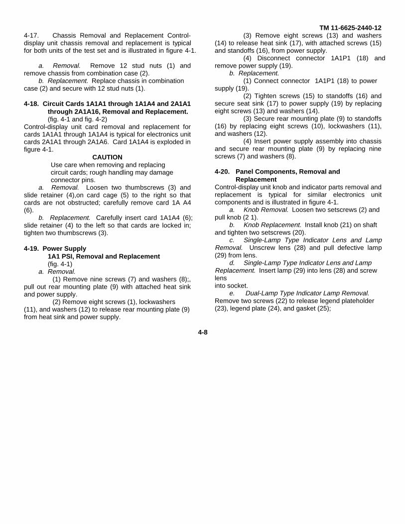
TM 11-6625-2440-124-17. Chassis Removal and Replacement Control-display unit chassis removal and replacement is typicalfor both units of the test set and is illustrated in figure 4-1.
a. Removal. Remove 12 stud nuts (1) andremove chassis from combination case (2).
b. Replacement. Replace chassis in combinationcase (2) and secure with 12 stud nuts (1).
4-18. Circuit Cards 1A1A1 through 1A1A4 and 2A1A1through 2A1A16, Removal and Replacement.(fig. 4-1 and fig. 4-2)
Control-display unit card removal and replacement forcards 1A1A1 through 1A1A4 is typical for electronics unitcards 2A1A1 through 2A1A6. Card 1A1A4 is exploded infigure 4-1.
CAUTIONUse care when removing and replacingcircuit cards; rough handling may damageconnector pins.
a. Removal. Loosen two thumbscrews (3) andslide retainer (4),on card cage (5) to the right so thatcards are not obstructed; carefully remove card 1A A4(6).
b. Replacement. Carefully insert card 1A1A4 (6);slide retainer (4) to the left so that cards are locked in;tighten two thumbscrews (3).
4-19. Power Supply1A1 PSI, Removal and Replacement(fig. 4-1)
a. Removal.(1) Remove nine screws (7) and washers (8);,
pull out rear mounting plate (9) with attached heat sinkand power supply.
(2) Remove eight screws (1), lockwashers(11), and washers (12) to release rear mounting plate (9)from heat sink and power supply.
(3) Remove eight screws (13) and washers(14) to release heat sink (17), with attached screws (15)and standoffs (16), from power supply.
(4) Disconnect connector 1A1P1 (18) andremove power supply (19).
b. Replacement.(1) Connect connector 1A1P1 (18) to power
supply (19).(2) Tighten screws (15) to standoffs (16) and
secure seat sink (17) to power supply (19) by replacingeight screws (13) and washers (14).
(3) Secure rear mounting plate (9) to standoffs(16) by replacing eight screws (10), lockwashers (11),and washers (12).
(4) Insert power supply assembly into chassisand secure rear mounting plate (9) by replacing ninescrews (7) and washers (8).
4-20. Panel Components, Removal andReplacement
Control-display unit knob and indicator parts removal andreplacement is typical for similar electronics unitcomponents and is illustrated in figure 4-1.
a. Knob Removal. Loosen two setscrews (2) andpull knob (2 1).
b. Knob Replacement. Install knob (21) on shaftand tighten two setscrews (20).
c. Single-Lamp Type Indicator Lens and LampRemoval. Unscrew lens (28) and pull defective lamp(29) from lens.
d. Single-Lamp Type Indicator Lens and LampReplacement. Insert lamp (29) into lens (28) and screwlensinto socket.
e. Dual-Lamp Type Indicator Lamp Removal.Remove two screws (22) to release legend plateholder(23), legend plate (24), and gasket (25);
4-8

TM 11-6625-2440-12
EL6625-2440-12-51. Stud nut(12) 7. Screw (9) 13. Screw (18) I9. Power Supply 1A1PS1 25. Gasket2. Combination case 1MP1 8 Washer (9) 14. Washer (8) 20. Set Screw (2) 26. Filter (2)3. Thumbscrew (2) 9. Rear mounting plate 15. Screw (8) 21. Knob 27. Lamp (2)4. Retainer 10. Screw (8) 16. Standoff (8) 22. Screw (2) 28. Lens5. Card cage 11. Lockwasher (8) 17. Heat sink 23. Legend plateholder 29. Lamp6. Card 1A1A4 12. Washer (8) 18. Connector 1A1PS 24. Legend plate
Figure 4-1. Control-display unit, exploded view. Change 1 4-9

TM 11-6625-2440-12
Figure 4-2. Electronics unit., exploded view.Change 1 4-10

TM 11-6625-2440-12remove filter (26) and pull defective lamp (27)from socket.
f. Dual-Lamp Type Indicator Lamp Replacement.Place lamp (27) in socket and install filter (26), gasket(25), legend plate (24), and legend plateholder (23) byreplacing two screws (22).
4-21. Circuit Card 2A1A17, Removal andReplacement
(fig. 4-2)a. Removal. Bend circuit card retainer upward
and carefully pull circuit card 2AlA17 from circuit cardholder.
b. Replacement. Bend circuit card retainerupward and carefully insert circuit card 2AlA17 into circuitcard holder.
4-11

TM 11-6625-2440-12CHAPTER 5
SHIPMENT, LIMITED STORAGE, AND DEMOLITION TO PREVENT ENEMY USE
Section I. SHIPMENT AND LIMITED STORAGE
5-1. Disassembly of EquipmentEquipment disassembly is not required. Disconnectcables shown in figure 2-2.
5-2. Repackaging for Shipment or Limited StorageThe exact procedure for repackaging depends on thematerial available and the conditions under which theequipment is to be shipped or stored. Refer toinformation concerning packaging in para 2-2.
Section II. DEMOLITION TO PREVENT ENEMY USE5-3. Authority for DemolitionThe demolition procedures given in paragraph 5-4should be used to prevent the enemy from using orsalvaging equipment. Demolition of the equipmentshould be executed only upon the order of thecommander.5-4. Methods of DestructionThe tactical situation and time available determine themethod used when destruction of equipment is ordered.In most cases, it is preferable to completely demolishsome portions of the equipment rather than partiallydestroy all the equipment units.
WARNINGMake sure that all power is disconnectedfrom the test set before committing anyacts of destruction. Failure to comply couldresult in serious injury or death fromelectrical shock or burns.
a. Smash. Use sledges, axes, hammers, crowbars, or any other heavy tools available to smashthe interior units of the test set.
(1) Use the heaviest tool available to smashthe connectors, dials, knobs, and switches.
(2) Remove the covers from the unit andsmash as many of the parts as possible.
b. Cut. Use axes, machetes, and similar tools tocut cabling, cording, and wiring. Cut all cords and cables
in a number of places.WARNING
Be extremely careful with explosives andincendiary devices. Use these items onlywhen the need is urgent.c. Burn. Burn technical manuals and diagrams
first. Burn as much of the equipment as is flammable;use flamethrowers, gasoline, oil, or similar materials.Pour gasoline on the cut cables and internal wiring andignite. Burn spare parts, or pour gasoline on the sparesand ignite them.
d. Explode. Use explosives to completedemolition. Powder charges, fragmentation grenades, orincendiary grenades may be used. Incendiary grenadesusually are most effective if destruction of small partsand wiring is desired.
(1) Use fragmentation grenades to destroy theinterior of the test set. Unlatch the fasteners on thefront cover of each unit. Open the front covers.Remove screws from the front panel of each unit.Pull the front panels forward and drop the grenadesinto the interior.
(2) For quick destruction of the test set, placean incendiary grenade on top of both units.e. Dispose. Bury or scatter destroyed parts or throwinto nearby waterways. This is particularly importantif a number of parts have not been completelydestroyed.
5-1

TM 11-6625-2440-12
5-5. Priorities for DestructionWhen lack of time prevents complete destruction ofequipment, use the priority number in the following list todetermine the priority of destruction of essential parts:
Item PriorityTechnical manuals .............................................1Power supply ....................................................2Circuit cards ....................................................3Cables ....................................................4GFE ....................................................5
5-6. Spare Parts DestructionUse list in paragraph 5-5 to determine the priority forspare parts destruction and then destroy equipment asspecified in paragraph 5-4.
5-7. Report of DestructionReport the destruction of equipment through commandchannels.
5-2

TM 11-6625-244-12
APPENDIX A
REFERENCES
The following publications contain information applicable to the operation and maintenance of Test Set, Gyro StabilizedPlatform AN/ASM385.DA Pam 310-4 Military Publications: Index of Technical Manuals, Technical Bulletins,
Supply Manuals (Types 7, 8, and 9), Supply Bulletins, and LubricationOrders
DA Pam 310-7 U.S. Army Equipment Index of Modification Work OrdersSB 38-100 Preservation, Packaging, Packing and Marketing Materials, Supplies and
Equipment used by the ArmyTB SIG 291 Safety Measures to be Observed When Installing and UsingWhip Antennas, Field Type Masts, Towers, Antennas, and Metal Poles Thatare Used With Communication, Radar, and Direction Finder Equipment
TB 746-10 Field Instructions for Painting and Preserving Electronics CommandEquipment.
TM 11-6625-2440-20P Organizational Maintenance Repair Parts and Special Tools List for TestSet, Gyro Stabilized Platform AN/ASM385.
TM 740-90-1 Administrative Storage of Equipment
A-1

TM 11-6625-244-12
APPENDIX B
MAINTENANCE ALLOCATIONSection I. INTRODUCTION
B-1. GeneralThis appendix provides a summary of the maintenanceoperations covered in the equipment literature. Itauthorizes categories of maintenance for specificmaintenance functions on repairable items andcomponents and the tools and equipment required toperform each function. This appendix may be used asan aid in planning maintenance operations.
B-2. Maintenance FunctionsMaintenance functions will be limited to and defined asfollows:
a. Inspect. To determine serviceability of an itemby comparing its physical, mechanical, and electricalcharacteristics with established standards.
b. Test. To verify serviceability and to detectincipient electrical or mechanical failure by use of specialequipment such as gages, meters, etc. This isaccomplished with external test equipment and does notinclude operation of the equipment and operator typetests using internal meters or indicating devices.
c. Service. To clean, to preserve, to charge, andto add fuel, lubricants, cooling agents, and air. If it isdesired that elements, such as painting and lubricating,be defined separately, they may be so listed.
d. Adjust. To rectify to the extent necessary tobring into proper operating range.
e. Align. To adjust two or more components orassemblies of an electrical or mechanical system so thattheir functions are properly synchronized. This does notinclude setting the frequency control knob of radioreceivers or transmitters to the desired frequency.
f. Calibrate. To determine the corrections to bemade in the readings of instruments or test equipmentused in precise measurement. Consists of thecomparison of
two instruments, one of which is a certified standard ofknown accuracy, to detect and adjust any discrepancy inthe accuracy of the instrument being compared with thecertified standard.
g. Install. To set up for use in an operationalenvironment such as an encampment, site, or vehicle. h. Replace. To replace unserviceable itemswith serviceable like items.
i. Repair. To restore an item to serviceablecondition through correction of a specific failure ofunserviceable condition. This function includes, but isnot limited to welding, grinding, riveting, straightening,and replacement of parts other than the trial and errorreplacement of running spare type items such as fuses,lamps, or electron tubes.
j. Overhaul. Normally, the highest degree ofmaintenance performed by the Army in order to minimizetime work in process is consistent with quality andeconomy of operation. It consists of that maintenancenecessary to restore an item to completely serviceablecondition as prescribed by maintenance standards intechnical publications for each item of equipment.Overhaul normally does not return an item to like new,zero mileage, or zero hour condition.
k. Rebuild. The highest degree of materielmaintenance. It consists of restoring equipment asnearly as possible to new condition in accordance withoriginal manufacturing standards. Rebuild is performedonly when required by operational considerations orother paramount factors and then only at the depotmaintenance category. Rebuild reduces to zero thehours or miles the equipment, or component thereof, hasbeen in use.
1. Symbols. The uppercase letter placed in theappropriate column indicates the lowest level at
B-1
TM 116625-2440-12
which that particular maintenance function is to beperformed.
B-3. Explanation of Formata. Column 1, Group Number. Column 1 lists
arbitrary group numbers, the purpose of which is toidentify components, assemblies, subassemblies, andmodules with the next higher assembly.
b. Column 2, Functional Group. Column 2 liststhe noun names of components, assemblies, subas-semblies, and modules on which maintenance isauthorized.
c. Column 3, Maintenance Functions. Column 3lists the maintenance category at which performance ofthe specific maintenance function is authorized.Authorization to perform a function at any category alsoincludes authorization to perform that function at highercategories. The codes used represent the variousmaintenance categories as follows:
Code Maintenance categoryC................... Operator/crew0 ................... Organizational maintenanceF ................... Direct support maintenanceH................... General support maintenanceD................... Depot maintenance
d. Column 4, Tools and Test Equipment.
Column 4 specifies, by code, those tools and testequipments required to perform the designated function.The numbers appearing in this column refer to specifictools and test equipment which are identified in table I.
e. Column 5, Remarks. Self-explanatory.
B-4. Explanation of Format of Table I, Tool and TestEquipment Requirements
The columns in table I are as follows:a. Tools and Equipment. The numbers in this
column coincide with the numbers used in the tools andequipment column of the applicable tool for themaintenance function.
b. Maintenance Category. The codes in thiscolumn indicate the maintenance category normallyallocated the facility.
c. Nomenclature. This column lists tools, test,and maintenance equipment required to perform themaintenance functions.
d. Federal Stock Number. This column lists theFederal stock number of the specific tool or testequipment.
e. Tool Number. Not used.
B-2
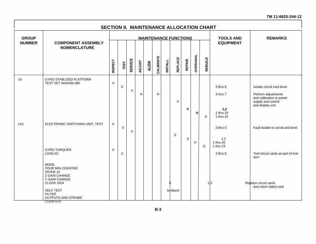
TM 11-6625-244-12
SECTION II. MAINTENANCE ALLOCATION CHART
GROUP MAINTENANCE FUNCTIONS TOOLS AND REMARKSNUMBER COMPONENT ASSEMBLY EQUIPMENT
NOMENCLATURE
1A GYRO STABLIZED PLATFORMTEST SET AN/ASM-385 0
0 3 thru 6 Isolate circuit card level.0
H H 3 thru 7 Perform adjustmentsand calibration to power
0 supply and controland display unit.
0 1,2H 1 thru 20
D 1 thru 23
1A1 ELECTRONIC SWITCHING UNIT, TEST 00 3 thru 6 Fault isolate to circuit and level.
00
0 1,2H 1 thru 20
D 1 thru 23GYRO TORQUER 0LOAD #2 0 3 thru 6 Test circuit cards as part of end
item
MODEFOUR MIN COUNTERDIVIDE x5Z GAIN CHANGEY GAIN CHANGECLOCK GEN 0 1,2 Replace circuit cards
and return failed cardSELF TEST to depot.FILTEROUTPUTS AND STROBECOUNTER
B-3

TM 11-6625-244-12
MAINTENANCE ALLOCATION CHART
GROUP MAINTENANCE FUNCTIONS TOOLS AND REMARKSNUMBER COMPONENT ASSEMBLY EQUIPMENT
NOMENCLATURE
1A2 CONTROL-DISPLAY, TEST SET 0C-8316/ASM-385 0 3 thru 6 Fault isolate to circuit card
level.0
H 3 thru 70
0 1,2H 1 thru 20
D 1 thru 23COMPONENT BOARD #1LAMP DRIVERMAG HEADINGTRUE HEADING 0
0 3 thru 6 Test circuit cards as part ofend item
0 1,2 Replace circuit cards andreturn failed card to depot.
1A2A1 POWER SUPPLY UNIT 00 3 thru 6 Test as part of end item
H H 3 thru 70 1,2
0 1,2 Repair by replacement ofcircuit cards
D 1 thru 23
+5V SWITCHING REG DREGULATOR TYPE IV D D D 3 thru 7, 21 - 23REGULATOR III 21 THRU 23COMPONENT ASSY D 1,2,8TRANSFORMERMODULE NO.1REG CONTROLLER
B-4

TM 11-6625-244-12
TABLE I. TOOL AND TEST EQUIPMENT REQUIREMENTSFEDERAL
TOOLS MAINTENANCE NOMENCLATURE STOCK TOOL NUMBEREQUIPMENT CATEGORY NUMBER
1 O TOOL KIT, ELECTRONIC EQUIPMENT TK-101/G 5180-064-5178
2 O,H,D TOOL KIT, ELECTRONIC EQUIPMENT TK-105/G 5180-610-8177
3 O,H,D VOLTMETER (FLUKE MODEL 887A)
4 O,H,D OSCILLOSCOPE AN/USM-281A 6625-179-8441
5 O,H,D COUNTER, ELECTRONIC DIGITAL READOUT AN/USM-207 6625-911-6368
6 O,H,D PHASE ANGLE VOLTMETER ME-223 6625-810-3917
7 H,D MULTIMETER AN/USM-223 6625-999-7465
8 H,D TOOL KIT, ELECTRONIC EQUIPMENT TK-100/G 5180-605-0079
9 H,D CONTACT LOCATOR (BENDIX P/N 11-8673-6)
10 H,D TERMI-POINT SERVICE TOOL (AMP INC P/N 69535)
11 H,D MANDREL (AMP INC P/N 69545-1)
12 H,D INSERTION TOOL (AMP INC P/N 69514)
13 H,D EXTRACTOR LOCATOR TOOL (AMP INC P/N 69357-5)
14 H,D INSERTION TOOL (HUGHES P/N TWO 22IT000)
15 H,D REMOVAL TOOL (HUGHES P/N TWO 22RT000)
16 H,D CRIMPING TOOL (AMP INC P/N 48698)
17 H,D REMOVAL TOOL (AMP INC P/N 380305-1)
18 H,D INSERTION TOOL (AMP INC P/N 380310-2)
19 H,D CRIMPING TOOL (DANIELS P/N MH 750-C HEAD)
20 H,D WIRE STRIPPER (GGG-S-793A)
21 D OSCILLATOR SG-621/U 6625-606-9727
B-5

TM 11-6625-244-12
TOOL AND TEST EQUIPMENT REQUIREMENTSFEDERAL
TOOLS MAINTENANCE NOMENCLATURE STOCK TOOL NUMBEREQUIPMENT CATEGORY NUMBER
22 D DUAL DC POWER SUPPLY (POWER DESIGN MODEL TW 5005)23 D POWER SUPPLY TESTER (LITTON MODEL TESK 209319)
B-6
TM 11-6625-2440-12
By Order of the Secretary of the Army:
W. C. WESTMORELAND,General, United States Army,
Official: Chief of Staff.VERNE L. BOWERS,Major General, United States Army,The Adjutant General.
Distribution:To be distributed in accordance with DA Form 1231, direct and general support maintenance requirements for the OV-1Dand U-21 aircraft.
. U.S. GOVERNMENT PRINTING OFFICE : 1985 0 - 461-202 (20388)


PIN NUMBER: 016237:

This fine document...
Was brought to you by me:
Liberated Manuals -- free army and government manuals
Why do I do it? I am tired of sleazy CD-ROM sellers, who take publicly available information, slap “watermarks” and other junk on it, and sell it. Those masters of search engine manipulation make sure that their sites that sell free information, come up first in search engines. They did not create it... They did not even scan it... Why should they get your money? Why are not letting you give those free manuals to your friends?
I am setting this document FREE. This document was made by the US Government and is NOT protected by Copyright. Feel free to share, republish, sell and so on.
I am not asking you for donations, fees or handouts. If you can, please provide a link to liberatedmanuals.com, so that free manuals come up first in search engines:
<A HREF=http://www.liberatedmanuals.com/>Free Military and Government Manuals</A>
– SincerelyIgor Chudovhttp://igor.chudov.com/
– Chicago Machinery Movers