tm 11-5855-316-10 sight,thermal,anpas 13c(v)1,anpas 13c(v)2,anpas 13c(v)3 august 2010
DESCRIPTION
Operator's Manual for The AN/PAS-13C Series Thermal SightTRANSCRIPT
*TM 11-5855-316-10
HEADQUARTERS DEPARTMENT OF THE ARMY
31 August 2010
DISTRIBUTION STATEMENT C - Distribution authorized to U.S. Government agencies and their contractors for administrative or operational use (15 June 2006). Other requests for this document shall be referred to Commander, U.S. Army CECOM Life Cycle Management Command (LCMC) and Fort Monmouth, ATTN: AMSEL-LC-LEO-E-CM, Fort Monmouth, New Jersey 07703-5006.
DESTRUCTION NOTICE – Destroy by any method that will prevent disclosure of contents or reconstruction of the document. WARNING - This document contains technical data whose export is restricted by the Arms Export Control Act (Title 22, U.S.C., Sec 2751, et seq.) or the Export Administration Act of 1979, as amended, Title 50A, U.S.C., App. Violations of these export laws are subject to severe criminal penalties. Disseminate in accordance with provisions of DOD Directive 5230.25.
TECHNICAL MANUAL OPERATOR’S MANUAL
AN/PAS-13C(V)1 SIGHT, THERMAL (NSN 5855-01-523-7707) (EIC: JG7)
AN/PAS-13C(V)2 SIGHT, THERMAL (NSN 5855-01-523-7713) (EIC: JH4)
AN/PAS-13C(V)3 SIGHT, THERMAL (NSN 5855-01-523-7715) (EIC: JNQ)
Description and Use of Operator Controls and
Indicators Page 2-1 2-1
Preventative MaintenanceChecks and Services (PMCS)
Page 2-48 2-2
Operation Under Usual
Conditions Page 2-61 2-3
Operator’s Troubleshooting Procedures Page 3-1 3
-1
Operator Maintenance Procedures Page 3-5 3
-2
*TM 11-5855-316-10 dated 31 August 2010 supersedes TM 11-5855-316-10 dated 15 June 2006, including all changes.

a
Warnings, Cautions, & Notes
Warnings, Cautions, and Notes are located throughout this document immediately prior to the point to which the information applies. Each occurrence is marked with an icon followed by explanatory text. Icons and their meanings are as follows:
WARNING Conditions, practices, or procedures that must be observed to
avoid personnel injury or loss of life.
CAUTION Conditions, practices, or procedures that must be observed to
avoid damage to, or destruction of, equipment.
NOTE Essential information of special importance, interest, or aid in job
performance.
b
WARNING SUMMARY
This warning summary contains general safety warnings and hazardous materials warnings that must be understood and applied during operation and maintenance of this equipment. Failure to observe these precautions could result in serious injury or death to personnel. Also included are explanations of safety and hazardous materials icons used within the technical manual.
WARNINGS • Do not touch, ingest, or inhale particles of a broken
objective lens. Lens contains germanium, which is slightly toxic if ingested or inhaled. Fragments may be sharp enough to cut personnel if touched.
• Do not open, crush, puncture or otherwise mutilate batteries. Handle leaking batteries with rubber or plastic gloves. Get medical attention for any skin or respiratory irritation.
• Batteries contain materials that are potentially hazardous and harmful to the environment. Turn depleted, leaking or damaged batteries in to next higher level of maintenance for disposal in accordance with unit Standard Operating Procedures (SOP).
• Do not expose batteries to open flame or high temperatures. Batteries may explode or leak and cause personnel injury.
• Do not expose batteries to water. Batteries may short circuit and/or flammable or noxious gas may be released that may cause a fire or injury to personnel.
• Do not install batteries backwards, mix types of batteries, or mix used/new batteries. Batteries may explode or leak and cause personnel injury and/or equipment damage.
• When using batteries other than the AA L91 (LiFeS2), the low battery indicator may not activate in time to provide sufficient warning to change batteries.
c
• Do not recharge AA L91 (LiFeS2) or alkaline batteries. Batteries may explode or leak and cause personnel injury. Refer to the Universal Battery Charger technical manual for directions on how to safely recharge the AA NiMH battery.
• Do not short-circuit battery terminals. Batteries may explode or leak flammable or noxious gas, causing injury to personnel or damage to equipment.
• Ensure weapon is not loaded and safety is on before installing or removing bracket/TWS to weapon. A loaded weapon may accidentally discharge, causing injury or death.
• Ensure weapon safeties are on before installing or removing bracket/TWS to weapon. A loaded weapon may accidentally discharge, causing injury or death.
• Remove eye from eyecup before firing MK19 machine gun. Recoil of MK19 machine gun may cause injury to personnel.
• Ensure safeties are in place before sight-aligning weapon. Weapon may accidentally discharge, causing injury or death.
• Unit deliberate decon SOP must be followed as the following procedures do not provide total decontamination. Protective mask and gloves should be worn when handling until total decontamination is completed by the decon lab.
• The TWS is not light secure in Emergency mode. Use Emergency mode only if circumstances do not require light discipline.
• Isopropyl alcohol vapors are harmful. Avoid prolonged or repeated breathing of vapors or solvent contact with skin. Use only with adequate ventilation. Isopropyl alcohol is flammable and should not be used near open flame. In the event of ingestion seek medical assistance.
• Do not store batteries in TWS. Heat generated from the system in transit case may cause TWS to become hot.

d
FIRST AID FOR FIRST AID OR ARTIFICIAL RESPIRATION, SEE FM 4-25.11,
FIRST AID.
ii (ii Blank)
DISTRIBUTION STATEMENT C - Distribution authorized to U.S. Government agencies and their contractors for administrative or operational use (15 June 2006). Other requests for this document shall be referred to Commander, U.S. Army CECOM Life Cycle Management Command (LCMC) and Fort Monmouth, ATTN: AMSEL-LC-LEO-E-CM, Fort Monmouth, New Jersey 07703-5006.
DESTRUCTION NOTICE – Destroy by any method that will prevent disclosure of contents or reconstruction of the document.
WARNING - This document contains technical data whose export is restricted by the Arms Export Control Act (Title 22, U.S.C., Sec 2751, et seq.) or the Export Administration Act of 1979, as amended, Title 50A, U.S.C., App. Violations of these export laws are subject to severe criminal penalties. Disseminate in accordance with provisions of DOD Directive 5230.25.
TECHNICAL MANUAL HEADQUARTERS DEPARTMENT OF THE ARMY
WASHINGTON, DC NO. 11-5855-316-10* 31 AUGUST 2010
OPERATOR’S MANUAL
AN/PAS-13C(V)1 SIGHT, THERMAL (NSN 5855-01-523-7707) (EIC: JG7)
AN/PAS-13C(V)2 SIGHT, THERMAL (NSN 5855-01-523-7713) (EIC: JH4)
AN/PAS-13C(V)3 SIGHT, THERMAL (NSN 5855-01-523-7715) (EIC: JNQ)
REPORTING ERRORS AND RECOMMENDING IMPROVEMENTS You can help improve this manual. If you find any mistakes or if you know of a way to improve the procedures, please let us know. Reports, as applicable by the requiring Service, should be submitted as follows:
Mail your letter or DA Form 2028 (Recommended Changes to Publications and Blank Forms) located in the back of this manual, directly to: Commander, U.S. Army CECOM Life Cycle Management Command (LCMC), ATTN: AMSEL-LC-LEO-E-CM, Fort Monmouth, NJ 07703-5006. You may also send in your recommended changes via electronic mail or by fax. Our fax number is 732-532-1556, DSN 992-1556. Our e-mail address is [email protected]. Our online web address for entering and submitting DA Form 2028s is http://edm.monmouth.army.mil/pubs/2028.html.
*TM 11-5855-316-10 dated 31 August 2010 supersedes TM 11-5855-316-10 dated 15 June 2006, including all changes.

ii
iii
TABLE OF CONTENTS CHAPTER 1 INTRODUCTION ...........................................................................1-1
Section 1 General Informat ion . . . . . . . . . . . . . . . . . . . . . . . . . . . . . . . . . . . 1-1 1-1.1 Scope.......................................................................................1-1
1-1.1.1 Type of Manual..................................................................1-1 1-1.1.2 Model Numbers and Equipment Names ..........................1-1 1-1.1.3 Purpose of Equipment .......................................................1-1
1-1.2 Maintenance Forms, Records and Reports...........................1-2 1-1.3 Corrosion Prevention and Control (CPC) ............................1-2 1-1.4 Destruction of Materiel to Prevent Enemy Use ...................1-2 1-1.5 Reporting Equipment Improvement Recommendations
(EIR) .......................................................................................1-3 1-1.6 Equipment Return Procedures...............................................1-4 1-1.7 Nomenclature Cross-Reference ............................................1-5 1-1.8 Quality Of Material................................................................1-5 1-1.9 List Of Abbreviations, Acronyms, and Symbols.................1-6
Section 2 Equipment Description & Data . . . . . . . . . . . . . . . . . . . . 1-9 1-2.1 Equipment Characteristics, Capabilities and Features ........1-9 1-2.2 Location and Description of Major Components.................1-9 1-2.3 Differences among Models ...................................................1-9 1-2.4 Equipment Data....................................................................1-10 1-2.5 Equipment Configuration....................................................1-10
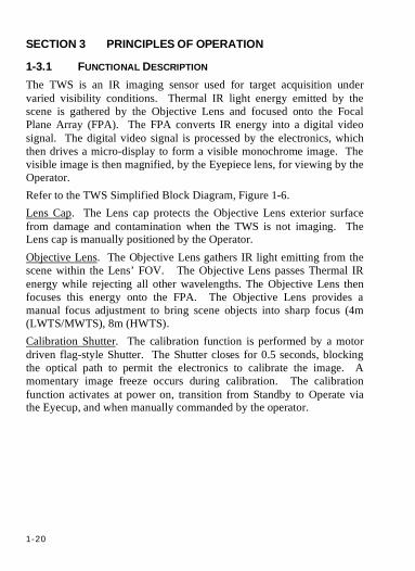
Section 3 Principles Of Operat ion . . . . . . . . . . . . . . . . . . . . . . . . . . . . . 1-20 1-3.1 Functional Description ........................................................1-20
CHAPTER 2 OPERATOR INSTRUCTIONS ....................................................2-1 Section 1 Description and Use of Operator Controls &
Indicators . . . . . . . . . . . . . . . . . . . . . . . . . . . . . . . . . . . . . . . . . . . . . . . . . . . 2-1 2-1.1 Description and Use of Operator Controls & Indicators
(Modes/States and Functions)...............................................2-1 2-1.1.1 TWS Controls ....................................................................2-1 2-1.1.2 TWS Display Indicators..................................................2-12
2-1.1.2.1 Startup and Shutdown Screens...................................2-12 2-1.1.2.2 Image Overlays............................................................2-14
2-1.1.3 TWS Reticles ...................................................................2-18 2-1.1.3.1 Common Reticle Indicators........................................2-18 2-1.1.3.2 Weapon/Application Specific Reticles ......................2-20

iv
Section 2 Prevent ive Maintenance Checks and Services (PMCS) . . . . . . . . . . . . . . . . . . . . . . . . . . . . . . . . . . . . . . . . . . . . . . . . . . . . . 2-48
2-2.1 Introduction to PMCS Table...............................................2-48 2-2.1.1 General.............................................................................2-48 2-2.1.2 Warnings and Cautions...................................................2-48 2-2.1.3 Explanation of Table Entries..........................................2-48
2-2.1.3.1 Item Number Column.................................................2-48 2-2.1.3.2 Interval Column ..........................................................2-48 2-2.1.3.3 Location Item to Check/Service Column ..................2-48 2-2.1.3.4 Procedure Column.......................................................2-49 2-2.1.3.5 Not Fully Mission Capable If: Column.....................2-49
2-2.2 PMCS Table.........................................................................2-49 Section 3 Operation Under Usual Conditions . . . . . . . . . . . . . 2-61
2-3.1 Assembly & Preparation for Use........................................2-61 2-3.1.1 Unpacking & Inspecting the Transit Case .....................2-61 2-3.1.2 Unpacking & Inspecting the Carrying Case..................2-62 2-3.1.3 Configuration of Rail Grabbers/Vertical Spacers .........2-64 2-3.1.4 Removal/Installation Of Batteries..................................2-67
2-3.1.4.1 Removal/Installation of Batteries In Cassettes .........2-68 2-3.1.4.2 Removal/Installation of Battery Cassettes.................2-70
2-3.2 Mounting/Removal..............................................................2-74 2-3.2.1 Mounting/Removal of TWS on M16A1/A2 Rifle ........2-74 2-3.2.2 Mounting/Removal of TWS on M4 Series Carbine or
M16A4 Rifle....................................................................2-76 2-3.2.3 Mounting/Removal of LWTS on M136 (AT4).............2-78 2-3.2.4 Mounting/Removal of MWTS on M249 Squad Automatic
Weapon (SAW) ...............................................................2-80 2-3.2.5 Mounting/Removal of MWTS on M240 Machine Gun2-82 2-3.2.6 Mounting/Removal of HWTS and M2 Bracket on M2
Heavy Machine Gun .......................................................2-84 2-3.2.7 Mounting/Removal of HWTS and MK19 Bracket on
MK19 Grenade Machine Gun ........................................2-89 2-3.2.8 Mounting/Removal of HWTS on M24 Sniper Rifle.....2-93 2-3.2.9 Mounting/Removal of HWTS on M107 Sniper Rifle...2-95
2-3.3 Operation..............................................................................2-97 2-3.3.1 Turn-On and Initial Adjustments ...................................2-97 2-3.3.2 Boresight, Zero & Sight Alignment...............................2-99
2-3.3.2.1 Thermal Zeroing Target Preparation .........................2-99 2-3.3.2.2 Zeroing and Sight Alignment...................................2-104
2-3.4 Preparation for Storage & Shipment ................................2-112
v
2-3.4.1 Removal of TWS from Weapon.................................. 2-112 2-3.4.2 Removal of Batteries and Battery Cassette................. 2-112 2-3.4.3 Packing the Carrying Case........................................... 2-112 2-3.4.4 Packing the Transit/Storage Case ................................ 2-113
Section 4 Operation Under Unusual Conditions . . . . . . . . 2-114 2-4.1 Operating in Inclement Weather/Environment............... 2-114
2-4.1.1 Extreme Cold ................................................................ 2-114 2-4.1.1.1 Objective Lens.......................................................... 2-114 2-4.1.1.2 Eyepiece Lens........................................................... 2-114
2-4.1.2 Extreme Heat ................................................................ 2-115 2-4.1.3 Rain, Fog, or Humidity ................................................ 2-115 2-4.1.4 Salt Water...................................................................... 2-116 2-4.1.5 Dust or Sand.................................................................. 2-116 2-4.1.6 Mud................................................................................ 2-116
2-4.2 Fording/Swimming ........................................................... 2-117 2-4.3 Nuclear, Biological and Chemical (NBC)
Decontamination............................................................... 2-118 2-4.3.1 Chemical Gross Liquid Decontamination................... 2-118 2-4.3.2 Biological Decontamination ........................................ 2-119 2-4.3.3 Nuclear Decontamination............................................. 2-119
2-4.4 Emergency Procedures ..................................................... 2-120 CHAPTER 3 OPERATOR MAINTENANCE INSTRUCTIONS ...................3-1
Section 1 Operator’s Troubleshooting Procedures . . . . . . . 3-1 3-1.1 Troubleshooting Table...........................................................3-1
Section 2 Operator Maintenance Procedures . . . . . . . . . . . . . . . 3-5 3-2.1 Exterior Cleaning...................................................................3-5 3-2.2 Eyecup Removal/Reinstallation............................................3-6
3-2.2.1 Removal .............................................................................3-6 3-2.2.2 Reinstallation .....................................................................3-6
3-2.3 Lens Cleaning.......................................................................3-10 3-2.4 Anti-fog Compound Application ........................................3-12 3-2.5 Battery Compartment, Cassette & Contact Cleaning ........3-13 3-2.6 Test & Inspection.................................................................3-13
APPENDIX A References . . . . . . . . . . . . . . . . . . . . . . . . . . . . . . . . . . . . . . . . . . . . . . . . . . . 3-1 A-1 Scope.......................................................................................3-1 A-2 Forms......................................................................................3-1 A-3 Technical Manuals.................................................................3-1 A-4 Other Publications..................................................................3-2

vi
APPENDIX B Components Of End Item (COEI) & Basic Issue Items (BII) . . . . . . . . . . . . . . . . . . . . . . . . . . . . . . . . . . . . . . . . . . . . . . . . . B-1
B-1 Introduction........................................................................... B-1 B-2 Components Of End Item .................................................... B-3 B-3 Basic Issue Items & Collateral Material ............................. B-5
APPENDIX C Additional Authorized List (AAL) . . . . . . . . . . . . . . . . C-1 C-1 Introduction........................................................................... C-1 C-2 Additional Authorized Items List ........................................ C-2
APPENDIX D Expendable and Durable Items List (EDIL) . . . D-1 D-1 Introduction...........................................................................D-1 D-2 Expendable and Durable Items List ....................................D-2
APPENDIX E Quick Reference Card .. . . . . . . . . . . . . . . . . . . . . . . . . . . . . . . . . E-1

vii
List Of Tables TABLE 1-1 TWS MAJOR COMPONENTS .................................................................. 1-12 TABLE 1-2 TWS COMPONENTS AND FEATURES..................................................... 1-15 TABLE 1-3 TWS WEAPONS APPLICATION MATRIX................................................ 1-16 TABLE 1-4 EQUIPMENT DATA.................................................................................. 1-17 TABLE 1-5 TWS BATTERY LIFE (EACH CASSETTE)................................................ 1-18 TABLE 1-6 LWTS VERTICAL SPACER CONFIGURATION MATRIX.......................... 1-19 TABLE 2-1 DESCRIPTION & USE OF TWS OPERATOR CONTROLS............................ 2-3 TABLE 2-2 TWS MODES, STATES & FUNCTIONS MATRIX ...................................... 2-7 TABLE 2-3 DESCRIPTION OF TWS MODES STATES & FUNCTIONS........................... 2-8 TABLE 2-4 TWS START-UP/SHUT-DOWN SCREEN COMPONENTS DESCRIPTION .. 2-12 TABLE 2-5 TWS INDICATORS AND WARNINGS ...................................................... 2-15 TABLE 2-6 TWS RETICLE APPLICATION MATRIX .................................................. 2-20 TABLE 2-7 M4/16 RETICLE ANGULAR DIMENSIONS (LWTS) ............................... 2-22 TABLE 2-8 M136 RETICLE ANGULAR DIMENSIONS ............................................... 2-24 TABLE 2-9 M4/16 RETICLE ANGULAR DIMENSIONS (MWTS) .............................. 2-28 TABLE 2-10 M249 RETICLE ANGULAR DIMENSIONS ............................................. 2-30 TABLE 2-11 M240 RETICLE ANGULAR DIMENSIONS ............................................. 2-32 TABLE 2-12 M4/16 RETICLE ANGULAR DIMENSIONS (HWTS) ............................. 2-36 TABLE 2-13 M2 RETICLE ANGULAR DIMENSIONS.................................................. 2-38 TABLE 2-14 MK19 RETICLE ANGULAR DIMENSIONS ............................................ 2-40 TABLE 2-15 M24 RETICLE ANGULAR DIMENSIONS ............................................... 2-42 TABLE 2-16 M107 RETICLE ANGULAR DIMENSIONS ............................................. 2-44 TABLE 2-17 TWS PMCS......................................................................................... 2-50 TABLE 2-18 RAIL GRABBER & VERTICAL SPACER CONFIGURATION MATRIX ...... 2-64 TABLE 2-19 M2 BRACKET CONTROLS & INDICATORS ........................................... 2-84 TABLE 2-20 MK19 BRACKET CONTROLS & INDICATORS...................................... 2-89 TABLE 2-21 ZERO OFFSETS ................................................................................... 2-103 TABLE 2-22 KD ZEROING RANGES BY WEAPON ................................................. 2-110 TABLE 2-23 KNOWN DISTANCE (KD) SHOT GROUP MOVEMENT PER CLICK ..... 2-110 TABLE 3-1 OPERATOR TROUBLESHOOTING PROCEDURES ........................................ 3-2

viii
List Of Figures FIGURE 1-1. FAMILY OF TWS VARIANTS ..................................................................1-1 FIGURE 1-2 TWS MAJOR COMPONENTS..................................................................1-11 FIGURE 1-3 LWTS COMPONENTS & FEATURES......................................................1-13 FIGURE 1-4 MWTS/HWTS COMPONENTS & FEATURES........................................1-14 FIGURE 1-5 LWTS VERTICAL SPACER CONFIGURATIONS ......................................1-19 FIGURE 1-6 TWS SIMPLIFIED BLOCK DIAGRAM .....................................................1-21 FIGURE 2-1 LOCATION OF TWS OPERATOR CONTROLS............................................2-2 FIGURE 2-2A TWS STARTUP SCREEN ......................................................................2-13 FIGURE 2-2B TWS SHUTDOWN SCREEN ..................................................................2-13 FIGURE 2-3 TWS INDICATORS AND WARNINGS ......................................................2-14 FIGURE 2-4 REGIONS OF INTEREST ..........................................................................2-17 FIGURE 2-5 NFOV AREA INDICATOR ......................................................................2-19 FIGURE 2-6A M4/M16 RETICLE (LWTS-WFOV) ..................................................2-23 FIGURE 2-6B M4/M16 RETICLE (LWTS-NFOV)...................................................2-23 FIGURE 2-7A M136 RETICLE (WFOV) ....................................................................2-25 FIGURE 2-7B M136 RETICLE (NFOV) .....................................................................2-25 FIGURE 2-8A NONE RETICLE (WFOV) ..................................................................2-27 FIGURE 2-8B NONE RETICLE (NFOV)....................................................................2-27 FIGURE 2-9A M4/M16 RETICLE (MWTS-WFOV) .................................................2-29 FIGURE 2-9B M4/M16 RETICLE (MWTS-NFOV)..................................................2-29 FIGURE 2-10A M249 RETICLE (WFOV) ..................................................................2-31 FIGURE 2-10B M249 RETICLE (NFOV) ...................................................................2-31 FIGURE 2-11A M240 RETICLE (WFOV) ..................................................................2-33 FIGURE 2-11B M240 RETICLE (NFOV) ...................................................................2-33 FIGURE 2-12A NONE RETICLE (WFOV) ................................................................2-35 FIGURE 2-12B NONE RETICLE (NFOV) .................................................................2-35 FIGURE 2-13A M4/16 RETICLE (HWTS-WFOV) ..................................................2-37 FIGURE 2-13B M4/16 RETICLE (HWTS-NFOV).....................................................2-37 FIGURE 2-14A M2 RETICLE (WFOV) ......................................................................2-39 FIGURE 2-14B M2 RETICLE (NFOV) .......................................................................2-39 FIGURE 2-15A MK19 RETICLE (WFOV) .................................................................2-41 FIGURE 2-15B MK19 RETICLE (NFOV) ..................................................................2-41 FIGURE 2-16A M24 RETICLE (WFOV) ....................................................................2-43 FIGURE 2-16B M24 RETICLE (NFOV) .....................................................................2-43 FIGURE 2-17A M107 RETICLE (WFOV) ..................................................................2-45 FIGURE 2-17B M107 RETICLE (NFOV) ...................................................................2-45 FIGURE 2-18A NONE RETICLE (WFOV) ................................................................2-47 FIGURE 2-18B NONE RETICLE (NFOV) .................................................................2-47 FIGURE 2-19 UNPACKING THE TRANSIT CASE .........................................................2-61 FIGURE 2-20 UNPACKING THE CARRYING CASE......................................................2-63
ix
FIGURE 2-21 STANDARD RAIL GRABBER AND VERTICAL SPACER CONFIGURATIONS....................................................................................... 2-65
FIGURE 2-22 M16A1/A2 RAIL GRABBER CONFIGURATION (LWTS ONLY) ......... 2-66 FIGURE 2-23 M24 MOUNT ASSEMBLY CONFIGURATION (HWTS ONLY) ............. 2-66 FIGURE 2-24A INSTALLATION OF BATTERIES IN BATTERY CASSETTES.................. 2-69 FIGURE 2-24B INSTALLATION OF BATTERIES IN BATTERY CASSETTES .................. 2-70 FIGURE 2-25A BATTERY CASSETTE INSTALLATION ................................................ 2-72 FIGURE 2-25B BATTERY CASSETTE INSTALLATION ................................................ 2-73 FIGURE 2-26 TWS MOUNTING ON M16A1/A2 RIFLE............................................ 2-75 FIGURE 2-27 TWS MOUNTING ON M4 SERIES CARBINE/M16A4 RIFLE............... 2-77 FIGURE 2-28 LWTS MOUNTING ON AT4 ............................................................... 2-79 FIGURE 2-29 MWTS MOUNTING ON M249 SQUAD AUTOMATIC WEAPON
(SAW)....................................................................................................... 2-81 FIGURE 2-30 MWTS MOUNTING ON M240 MACHINE GUN .................................. 2-83 FIGURE 2-31 M2 BRACKET...................................................................................... 2-84 FIGURE 2-32 HWTS MOUNTING ON M2 HEAVY MACHINE GUN .......................... 2-88 FIGURE 2-33 MK19 BRACKET................................................................................. 2-89 FIGURE 2-34 HWTS MOUNTING ON MK19 GRENADE MACHINE GUN................. 2-92 FIGURE 2-35 HWTS MOUNTING ON M24 SNIPER RIFLE ....................................... 2-94 FIGURE 2-36 HWTS MOUNTING ON M107 SNIPER RIFLE ..................................... 2-96 FIGURE 2-37. SQUARE HOLE CUT IN A M16A2 25M ZEROING TARGET .............. 2-101 FIGURE 2-38 CORRUGATED CARDBOARD FRAME................................................. 2-101 FIGURE 2-39 THERMALIZED E-TYPE SILHOUETTE WITH MODIFIED M16A2 25M
ZEROING TARGET..................................................................................... 2-102 FIGURE 2-40 M16A2 25M ZEROING TARGET ....................................................... 2-107 FIGURE 3-1A EYECUP REMOVAL/REINSTALLATION.................................................. 3-8 FIGURE 3-1B EYECUP REMOVAL/REINSTALLATION.................................................. 3-8 FIGURE 3-1C EYECUP REMOVAL/REINSTALLATION.................................................. 3-8 FIGURE 3-1D EYECUP REMOVAL/REINSTALLATION.................................................. 3-8 FIGURE 3-1E EYECUP REMOVAL/REINSTALLATION .................................................. 3-9 FIGURE 3-1F EYECUP REMOVAL/REINSTALLATION .................................................. 3-9 FIGURE 3-1G EYECUP REMOVAL/REINSTALLATION.................................................. 3-9
x
HOW TO USE THIS MANUAL The safest, easiest, and most efficient way to operate and maintain the Thermal Weapon Sight (TWS) is to use this manual. Knowing what’s in this manual and how to use it will save you time and work, so take the time to learn how to use it. If this is the first time you are using this manual, be sure to completely read this section first. ORGANIZATION This manual is divided into four chapters: Chapter 1: Introduction – provides:
• General Information • Equipment Description and Data • Principles of Operation
Chapter 2: Operating Instructions – provides: • Description of Operator Controls and Indicators • Preventive Maintenance Checks and Services • Procedures for Operation Under Usual Conditions • Procedures for Operation Under Unusual Conditions
Chapter 3: Operator Maintenance Instructions – provides: • Operator Troubleshooting Procedures • Operator Maintenance Procedures
Appendix: Supporting Data – includes: • References • Components Of End Item (COEI) & Basic Issue Items (BII) • Additional Authorized List (AAL) • Expendable and Durable Items List (EDIL) • Quick Reference Card
WHERE TO START
If you’re using the manual for operating instructions, you will locate the procedures in the Operating Instructions, Chapter 2. If you are using the manual to replace a part (e.g., batteries) that you already know is bad, you will locate the replacement procedure in the Operator Maintenance Instructions in Chapter 3. If you do not know why a specific malfunction exists with the TWS, perform TWS Troubleshooting
xi
procedures located in the Operator Troubleshooting Procedures in Chapter 3. Before performing a procedure, read through it to determine if you have everything you need to perform the job. Familiarize yourself with the potential hazards described by the WARNINGS and CAUTIONS. You must familiarize yourself with the entire maintenance procedure before beginning the maintenance task. HOW TO USE A MAINTENANCE PROCEDURE
The first page of a maintenance procedure, which is referred to as the setup page, contains supplementary support information you will need to perform that procedure. The following paragraphs describe all the blocks of information you will find there. TOOLS: If any tools are required, the tool will be listed as the first item under this heading. SUPPLIES: If any expendable or durable supplies are needed to perform the task, they are listed under this heading along with a reference to the item in Appendix D. If more than one of an item is required, the required quantity is provided. Appendix D gives you all the detailed information necessary to requisition the item if you don’t have it on hand. REFERENCING WITHIN THIS MANUAL
Referencing from one procedure to another within this manual is by paragraph number. Paragraph references are preceded by the character “¶”. When you are referred to another procedure, you must read the setup page information for that procedure to determine what supplies may be required. SPECIAL FEATURES
The front cover index lists the sections of the manual most commonly used. Bleeder edge tabs are used to quickly locate these sections in the manual. To locate a section, find the bleeder edge on the side of the manual that aligns with the bleeder edge on the front cover, and open to that page. The title of the section is boxed on that page.
xi (xii Blank)

xii
1-1
CHAPTER 1 INTRODUCTION
SECTION 1 GENERAL INFORMATION
1-1.1 SCOPE
1-1.1.1 TYPE OF MANUAL This Operator’s Manual contains a system description, operating procedures and Operator Preventive Maintenance, Checks and Services (PMCS) procedures for the Thermal Weapon Sight (TWS).
1-1.1.2 MODEL NUMBERS AND EQUIPMENT NAMES AN/PAS-13C(V)1 SIGHT, THERMAL..........Light Weapon Thermal Sight (LWTS) AN/PAS-13C(V)2 SIGHT, THERMAL....Medium Weapon Thermal Sight (MWTS) AN/PAS-13C(V)3 SIGHT, THERMAL....... Heavy Weapon Thermal Sight (HWTS)
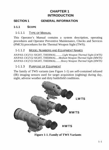
1-1.1.3 PURPOSE OF EQUIPMENT The family of TWS variants (see Figure 1-1) are self-contained infrared (IR) imaging sensors used for target acquisition (sighting) during day, night, adverse weather and dirty battlefield conditions.
Figure 1-1. Family of TWS Variants
HWTS
MWTS
LWTS
1-2
1-1.2 MAINTENANCE FORMS, RECORDS AND REPORTS Department of the Army forms and procedures used for equipment maintenance will be those prescribed by DA PAM 750-8, The Army Maintenance Management System (TAMMS) Users Manual.
1-1.3 CORROSION PREVENTION AND CONTROL (CPC) Corrosion Prevention and Control (CPC) of Army materiel is a continuing concern. It is important that any corrosion problems with this item be reported so that the problem can be corrected and improvements can be made to prevent the problem in future items. Corrosion specifically occurs with metals. It is an electrochemical process that causes the degradation of metals. It is commonly caused by exposure to moisture, acids, bases, or salts. An example is the rusting of iron. Corrosion damage in metals can be seen, depending on the metal, as tarnishing, pitting, fogging, surface residue, and/or cracking. Plastics, composites, and rubbers can also degrade. Degradation is caused by thermal (heat), oxidation (oxygen), solvation (solvents), or photolytic (light, typically UV) processes. The most common exposures are excessive heat or light. Damage from these processes will appear as cracking, softening, swelling, and/or breaking. Deficiencies should be submitted to the address specified in DA PAM 750-8.
1-1.4 DESTRUCTION OF MATERIEL TO PREVENT ENEMY USE For Army personnel, instructions for destruction of equipment to prevent enemy use: refer to TM 750-244-2.
1-3
1-1.5 REPORTING EQUIPMENT IMPROVEMENT RECOMMENDATIONS (EIR)
If your TWS needs improvement, let us know. Send us an EIR. You, the user, are the only one who can tell us what you don’t like about your equipment. Let us know why you don’t like the design or performance. Put it on an SF 368 (Product Quality Deficiency Report). Mail it to us at Commander, U.S. Army CECOM LCMC, ATTN: AMSEL-LC-LEO-S, Fort Monmouth, NJ 07703-5006. We will send you a reply. You can help improve this manual. If you find any mistakes or if you know of a way to improve the procedures, please let us know. Reports, as applicable by the requiring Service, should be submitted as follows:
Mail your letter or DA Form 2028 (Recommended Changes to Publications and Blank Forms) located in the back of this manual, directly to: Commander, U.S. Army CECOM Life Cycle Management Command (LCMC), ATTN: AMSEL-LC-LEO-E-CM, Fort Monmouth, NJ 07703-5006. You may also send in your recommended changes via electronic mail or by fax. Our fax number is 732-532-1556, DSN 992-1556. Our e-mail address is [email protected]. Our online web address for entering and submitting DA Form 2028s is http://edm.monmouth.army.mil/pubs/2028.html.
1-4
1-1.6 EQUIPMENT RETURN PROCEDURES The Thermal Weapon Sight (TWS) is warranted for the earlier of two years from the acceptance date on the TWS name plate, or 100 operating hours as displayed on the TWS shut down screen or read via the serial port, to conform to design and manufacturing requirements, to remain free from defects in materials and workmanship, and to conform to established performance specifications.
NOTE This warranty does not cover any product that has been subject
to misuse, neglect, accident, installation, or maintenance in violation of the instructions in TM 11-5855-316-10.
1. The Operator, after completing the PMCS and Troubleshooting, annotates the fault on DA Form 5988-E, completes the appropriate blocks, and turns in the TWS to the maintainer.
2. The maintainer will perform all PMCS and Troubleshooting before determining that the TWS does not show any faults or must be sent to the Field Maintenance activity for packing and shipping to the supporting IEW/RSC. The maintainer will annotate DA Form 5990-E and include this form with the TWS when sending the system to the DS shop.
The Field maintainer will notify their supporting IEW/RSC and follow procedures in the TWS Product Support Bulletin to obtain a replacement TWS for the unit.

1-5
1-1.7 NOMENCLATURE CROSS-REFERENCE NOMENCLATURE COMMON NAME
AN/PAS-13C(V)1 Sight, Thermal Light Weapon Thermal Sight (LWTS) AN/PAS-13C(V)2 Sight, Thermal Medium Weapon Thermal Sight (MWTS) AN/PAS-13C(V)3 Sight, Thermal Heavy Weapon Thermal Sight (HWTS)
NOTE TWS, as used in this manual, refers collectively to all three
variants. The terms AN/PAS-13C(V)1 or LWTS, AN/PAS-13C(V)2 or MWTS and AN/PAS-13C(V)3 or HWTS refer to the specific
variants.
1-1.8 QUALITY OF MATERIAL Material used for replacement, repair, or modification must meet the requirements of this manual. If quality-of-material requirements are not stated in this manual, the material must meet the requirements of the drawings, standards, specifications, or approved engineering change proposals applicable to the subject equipment.
1-6
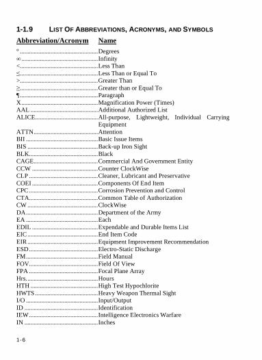
1-1.9 LIST OF ABBREVIATIONS, ACRONYMS, AND SYMBOLS Abbreviation/Acronym Name ° ...................................................Degrees ∞ ..................................................Infinity <...................................................Less Than ≤...................................................Less Than or Equal To >...................................................Greater Than ≥...................................................Greater than or Equal To ¶...................................................Paragraph X..................................................Magnification Power (Times) AAL ............................................Additional Authorized List ALICE.........................................All-purpose, Lightweight, Individual Carrying
Equipment ATTN..........................................Attention BII ...............................................Basic Issue Items BIS ..............................................Back-up Iron Sight BLK.............................................Black CAGE..........................................Commercial And Government Entity CCW ...........................................Counter ClockWise CLP .............................................Cleaner, Lubricant and Preservative COEI ...........................................Components Of End Item CPC.............................................Corrosion Prevention and Control CTA.............................................Common Table of Authorization CW ..............................................ClockWise DA...............................................Department of the Army EA ...............................................Each EDIL ...........................................Expendable and Durable Items List EIC ..............................................End Item Code EIR ..............................................Equipment Improvement Recommendation ESD.............................................Electro-Static Discharge FM...............................................Field Manual FOV.............................................Field Of View FPA .............................................Focal Plane Array Hrs...............................................Hours HTH ............................................High Test Hypochlorite HWTS .........................................Heavy Weapon Thermal Sight I/O ...............................................Input/Output ID ................................................Identification IEW.............................................Intelligence Electronics Warfare IN ................................................Inches

1-7
IR.................................................InfraRed JTA..............................................Joint Table of Allowances KD ...............................................Known Distance lb..................................................Pound LBS..............................................Laser Borelight System LCD.............................................Liquid Crystal Display LED.............................................Light Emitting Diode LiFeS2..........................................Lithium Iron Disulfide LWTS..........................................Light Weapon Thermal Sight m..................................................Meter MOA ...........................................Minutes Of Angle MOLLE.......................................Modular Lightweight Load-bearing Equipment MOPP .........................................Mission Oriented Protective Posture MTOE .........................................Modified Table Of Equipment MWTS.........................................Medium Weapon Thermal Sight N/A..............................................Not Applicable NBC.............................................Nuclear, Biological and Chemical NFOV..........................................Narrow Field Of View NiMH ..........................................Nickel Metal Hydride NSN.............................................National Stock Number NTSC ..........................................National Television Systems Committee NUC ............................................Non-Uniformity Correction PAM ............................................Pamphlet Pd/r ................................................Probability of Detection/Recognition PMCS ..........................................Preventive Maintenance Checks and Services POC.............................................Point Of Contact QRC.............................................Quick Reference Card Qty...............................................Quantity RMA............................................Return Material Authorization ROI ..............................................Region Of Interest RSC .............................................Regional Support Center SAW............................................Squad Automatic Weapon SF.................................................Standard Form SOP..............................................Standard Operating Procedure TAMMS......................................The Army Maintenance Management System TDA.............................................Table of Distribution and Allowances TM...............................................Technical Manual TWS ............................................Thermal Weapon Sight U.S...............................................United States U/I................................................Unit of Issue UOC ............................................Usable On Code UV ...............................................Ultra-Violet

1-8
W.................................................Watts WFOV.........................................Wide Field Of View WHT ...........................................White
1-9
SECTION 2 EQUIPMENT DESCRIPTION & DATA
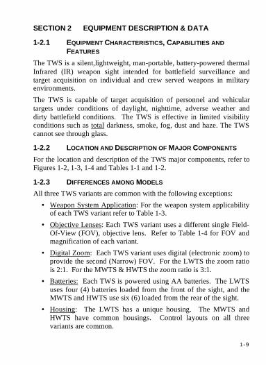
1-2.1 EQUIPMENT CHARACTERISTICS, CAPABILITIES AND FEATURES
The TWS is a silent, lightweight, man-portable, battery-powered thermal Infrared (IR) weapon sight intended for battlefield surveillance and target acquisition on individual and crew served weapons in military environments. The TWS is capable of target acquisition of personnel and vehicular targets under conditions of daylight, nighttime, adverse weather and dirty battlefield conditions. The TWS is effective in limited visibility conditions such as total darkness, smoke, fog, dust and haze. The TWS cannot see through glass.
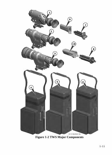
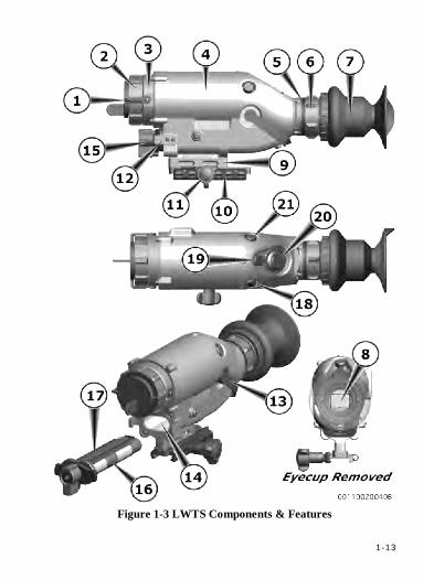
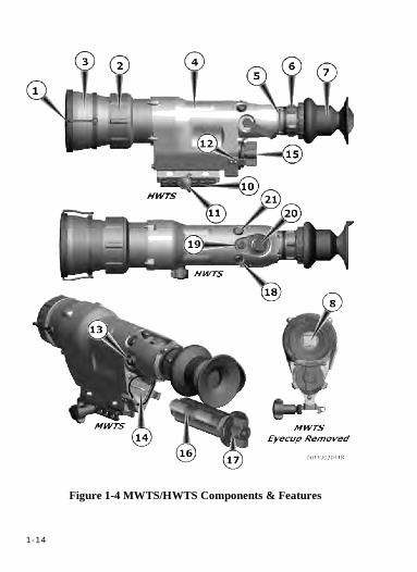
1-2.2 LOCATION AND DESCRIPTION OF MAJOR COMPONENTS For the location and description of the TWS major components, refer to Figures 1-2, 1-3, 1-4 and Tables 1-1 and 1-2.
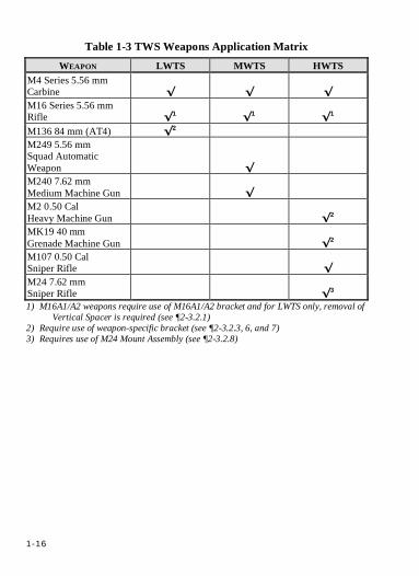
1-2.3 DIFFERENCES AMONG MODELS All three TWS variants are common with the following exceptions:
• Weapon System Application: For the weapon system applicability of each TWS variant refer to Table 1-3.
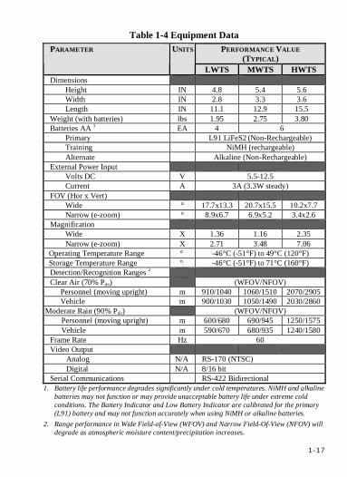
• Objective Lenses: Each TWS variant uses a different single Field-Of-View (FOV), objective lens. Refer to Table 1-4 for FOV and magnification of each variant.
• Digital Zoom: Each TWS variant uses digital (electronic zoom) to provide the second (Narrow) FOV. For the LWTS the zoom ratio is 2:1. For the MWTS & HWTS the zoom ratio is 3:1.
• Batteries: Each TWS is powered using AA batteries. The LWTS uses four (4) batteries loaded from the front of the sight, and the MWTS and HWTS use six (6) loaded from the rear of the sight.
• Housing: The LWTS has a unique housing. The MWTS and HWTS have common housings. Control layouts on all three variants are common.
1-10
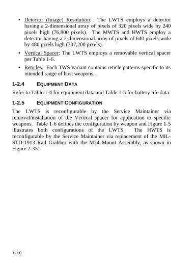
• Detector (Image) Resolution: The LWTS employs a detector having a 2-dimensional array of pixels of 320 pixels wide by 240 pixels high (76,800 pixels). The MWTS and HWTS employ a detector having a 2-dimensional array of pixels of 640 pixels wide by 480 pixels high (307,200 pixels).
• Vertical Spacer: The LWTS employs a removable vertical spacer per Table 1-6.
• Reticles: Each TWS variant contains reticle patterns specific to its intended range of host weapons.
1-2.4 EQUIPMENT DATA Refer to Table 1-4 for equipment data and Table 1-5 for battery life data.
1-2.5 EQUIPMENT CONFIGURATION The LWTS is reconfigurable by the Service Maintainer via removal/installation of the Vertical spacer for application to specific weapons. Table 1-6 defines the configuration by weapon and Figure 1-5 illustrates both configurations of the LWTS. The HWTS is reconfigurable by the Service Maintainer via replacement of the MIL-STD-1913 Rail Grabber with the M24 Mount Assembly, as shown in Figure 2-35.
1-11
Figure 1-2 TWS Major Components

1-12
Table 1-1 TWS Major Components KEY DESCRIPTION NOTES
1 LIGHT WEAPON THERMAL SIGHT (LWTS) 1 2 MEDIUM WEAPON THERMAL SIGHT (MWTS) 1 3 HEAVY WEAPON THERMAL SIGHT (HWTS) 1 4 CARRYING CASE, LWTS 5 CARRYING CASE, MWTS 6 CARRYING CASE, HWTS 7 BATTERY CASSETTE, LWTS 2 8 BATTERY CASSETTE, MWTS/HWTS 2 9 CASSETTE CASE, LWTS 10 CASSETTE CASE, MWTS/HWTS
1) TWS Exterior surface color may vary, either black, gray or a combination of the two.
2) Physical appearance (form and color) and latch function may vary. All LWTS Battery Cassettes are interchangeable. All MWTS/HWTS Battery Cassettes are interchangeable.
1-13
Figure 1-3 LWTS Components & Features
1-14
Figure 1-4 MWTS/HWTS Components & Features

1-15
Table 1-2 TWS Components And Features1 KEY COMPONENT DESCRIPTION
1 Lens Cap Rubber cap provides protection to objective lens surface when not in use.
2 Focus Ring2 Adjusts scene focus. 3 Objective Lens Gathers IR emissions from the scene and focuses it on
the FPA– determines system FOV and magnification. 4 Housing Houses FPA, electronics and control interfaces. 5 Eyepiece Displays and magnifies thermal image, reticles and
symbology for viewing by the Operator. 6 Diopter Ring2 Adjusts display focus. 7 Eyecup2 Rubber cup provides a light tight seal to Operator’s
face, properly positions the Operators eye for viewing, and provides standby override function.
8 Display Provides a visible image of the infrared scene emissions.
9 Vertical Spacer Spacer used for proper positioning of LWTS on M4/M16A4 weapons with integral rail. Removed for use on weapons with non-detachable handles.
10 Weapon Mount (Rail Grabber)
Universal (MIL-STD-1913) attachment interface between TWS and Weapon Bracket (“Picatinny Rail”).
11 Torque-limiting knob Ratcheting knob tightens Rail Grabber to weapon rail. 12 Barrel Hooks (x2) Retains battery Cassette in closed position. 13 I/O Port Input/Output connector – Allows use of external power,
external video monitor and serial communications for maintenance use.
14 Battery Compartment
Environmentally sealed compartment for holding TWS Battery Cassettes.
15 Battery Latch Retains Battery Cassette. Push and rotate to open/close. 16 Batteries Provide power for operation of TWS. 17 Battery Cassette Holds Batteries. 18 On/Off Switch2 Turns TWS On/Off and toggles image polarity. 19 Mode Switch2 Selects TWS Mode and Function Switch action. 20 Function Switch2 Adjusts gain/level, display brightness, reticle position,
selects reticle and ROI. 21 FOV Switch2 Toggle FOV between Wide and Narrow. 1) Table applies to Figures 1-3, & 1-4. 2) See ¶2-1.1 for complete description of Operator Controls.
1-16
Table 1-3 TWS Weapons Application Matrix WEAPON LWTS MWTS HWTS
M4 Series 5.56 mm Carbine √ √ √ M16 Series 5.56 mm Rifle √1 √1 √1 M136 84 mm (AT4) √2 M249 5.56 mm Squad Automatic Weapon √ M240 7.62 mm Medium Machine Gun √ M2 0.50 Cal Heavy Machine Gun √2 MK19 40 mm Grenade Machine Gun √2 M107 0.50 Cal Sniper Rifle √ M24 7.62 mm Sniper Rifle √3 1) M16A1/A2 weapons require use of M16A1/A2 bracket and for LWTS only, removal of
Vertical Spacer is required (see ¶2-3.2.1) 2) Require use of weapon-specific bracket (see ¶2-3.2.3, 6, and 7) 3) Requires use of M24 Mount Assembly (see ¶2-3.2.8)
1-17
Table 1-4 Equipment Data PERFORMANCE VALUE
(TYPICAL) PARAMETER UNITS
LWTS MWTS HWTS Dimensions
Height IN 4.8 5.4 5.6 Width IN 2.8 3.3 3.6 Length IN 11.1 12.9 15.5
Weight (with batteries) lbs 1.95 2.75 3.80 Batteries AA 1 EA 4 6
Primary L91 LiFeS2 (Non-Rechargeable) Training NiMH (rechargeable) Alternate Alkaline (Non-Rechargeable)
External Power Input Volts DC V 5.5-12.5 Current A 3A (3.3W steady)
FOV (Hor x Vert) Wide ° 17.7x13.3 20.7x15.5 10.2x7.7 Narrow (e-zoom) ° 8.9x6.7 6.9x5.2 3.4x2.6
Magnification Wide X 1.36 1.16 2.35 Narrow (e-zoom) X 2.71 3.48 7.06
Operating Temperature Range ° -46°C (-51°F) to 49°C (120°F) Storage Temperature Range ° -46°C (-51°F) to 71°C (160°F) Detection/Recognition Ranges 2 Clear Air (70% Pd/r) (WFOV/NFOV)
Personnel (moving upright) m 910/1040 1060/1510 2070/2905 Vehicle m 900/1030 1050/1490 2030/2860
Moderate Rain (90% Pd/r) (WFOV/NFOV) Personnel (moving upright) m 600/680 690/945 1250/1575 Vehicle m 590/670 680/935 1240/1580
Frame Rate Hz 60 Video Output
Analog N/A RS-170 (NTSC) Digital N/A 8/16 bit
Serial Communications RS-422 Bidirectional 1. Battery life performance degrades significantly under cold temperatures. NiMH and alkaline
batteries may not function or may provide unacceptable battery life under extreme cold conditions. The Battery Indicator and Low Battery Indicator are calibrated for the primary (L91) battery and may not function accurately when using NiMH or alkaline batteries.
2. Range performance in Wide Field-of-View (WFOV) and Narrow Field-Of-View (NFOV) will degrade as atmospheric moisture content/precipitation increases.
1-18
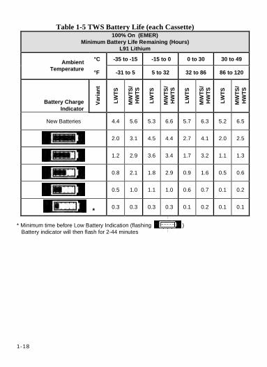
Table 1-5 TWS Battery Life (each Cassette) 100% On (EMER)
Minimum Battery Life Remaining (Hours) L91 Lithium
°C -35 to -15 -15 to 0 0 to 30 30 to 49 Ambient Temperature °F -31 to 5 5 to 32 32 to 86 86 to 120
Battery Charge Indicator
Varia
nt
LWTS
MW
TS/
HWTS
LWTS
MW
TS/
HWTS
LWTS
MW
TS/
HWTS
LWTS
MW
TS/
HWTS
New Batteries 4.4 5.6 5.3 6.6 5.7 6.3 5.2 6.5
2.0 3.1 4.5 4.4 2.7 4.1 2.0 2.5
1.2 2.9 3.6 3.4 1.7 3.2 1.1 1.3
0.8 2.1 1.8 2.9 0.9 1.6 0.5 0.6
0.5 1.0 1.1 1.0 0.6 0.7 0.1 0.2
* 0.3 0.3 0.3 0.3 0.1 0.2 0.1 0.1
* Minimum time before Low Battery Indication (flashing ) Battery indicator will then flash for 2-44 minutes

1-19
Figure 1-5 LWTS Vertical Spacer Configurations Table 1-6 LWTS Vertical Spacer Configuration Matrix
WEAPON RAIL
CONFIGURATION BRACKET VERTICAL
SPACER
M16A1/A2 Handle M16A1/A2 No
M16A4 Integral N/A Yes
M4 Series Integral N/A Yes
M136 N/A M136 Optional
1-20
SECTION 3 PRINCIPLES OF OPERATION
1-3.1 FUNCTIONAL DESCRIPTION The TWS is an IR imaging sensor used for target acquisition under varied visibility conditions. Thermal IR light energy emitted by the scene is gathered by the Objective Lens and focused onto the Focal Plane Array (FPA). The FPA converts IR energy into a digital video signal. The digital video signal is processed by the electronics, which then drives a micro-display to form a visible monochrome image. The visible image is then magnified, by the Eyepiece lens, for viewing by the Operator. Refer to the TWS Simplified Block Diagram, Figure 1-6. Lens Cap. The Lens cap protects the Objective Lens exterior surface from damage and contamination when the TWS is not imaging. The Lens cap is manually positioned by the Operator. Objective Lens. The Objective Lens gathers IR light emitting from the scene within the Lens’ FOV. The Objective Lens passes Thermal IR energy while rejecting all other wavelengths. The Objective Lens then focuses this energy onto the FPA. The Objective Lens provides a manual focus adjustment to bring scene objects into sharp focus (4m (LWTS/MWTS), 8m (HWTS). Calibration Shutter. The calibration function is performed by a motor driven flag-style Shutter. The Shutter closes for 0.5 seconds, blocking the optical path to permit the electronics to calibrate the image. A momentary image freeze occurs during calibration. The calibration function activates at power on, transition from Standby to Operate via the Eyecup, and when manually commanded by the operator.
1-21
Figure 1-6 TWS Simplified Block Diagram
1-22
FPA. The FPA converts incident IR energy into a digital video signal. Electronics. The electronics:
• Convert and regulate power supplied from the Batteries or an external power source connected to the I/O port, into the voltages necessary to operate the electronics.
• Processes the Operator control inputs. • Provides the drive signal for the Shutter Motor. • Store TWS programming. • Processes the raw digital video from the FPA, including Non-
Uniformity Correction (NUC), gain, level, polarity, electronic zoom (FOV), and overlay of reticles and symbology.
• Drives the Liquid-Crystal Display (LCD). • Converts the processed digital video stream to an RS-170 analog
video signal suitable for driving television monitors and outputs this signal via the I/O port.
• Provides a digital video stream output of either raw or processed digital video to the I/O port for maintenance use.
• Provides a RS-422 serial communications interface for the TWS via the I/O Port for maintenance purposes.
Backlight. The Backlight is a Light Emitting Diode (LED) illumination source for the LCD. The Backlight is illuminated by the standby override switch or in emergency mode. The Brightness level of the Backlight is adjustable by the Operator. Display. The LCD converts the Processed Video stream into a visible, monochrome image. Eyepiece Lens. The Eyepiece Lens magnifies the visible image from the display for viewing by the Operator. The Eyepiece provides a manual Operator diopter adjustment to set the display focus to the users eye (–6 to +2 Diopters).
1-23
Eyecup. The Eyecup provides a light seal to the Operator’s face for light security and to prevent glare. Compression of the Eyecup activates the Standby Override switch transitioning TWS from Standby to Operate. The eyecup properly positions the user’s eye for optimal viewing of the display. The Eyecup provides limited recoil protection to the Operator. The Eyecup contains flaps to assist in light security and minimize entrapment of debris and lens contamination. Batteries. AA Batteries loaded in a removable cassette provide the power source to operate the TWS when not powered from an external source (via the I/O connector). Controls. The Control interface allow the user to select or adjust the following: mode, brightness, gain, level, polarity, FOV, reticle selection, reticle adjustment and reticle polarity. With the exception of Mode, controls are inactive in Standby. See ¶2-1 for a detailed description of control functions. I/O Port. The I/O port is a connector interface for providing external power, outputting analog or digital video, and performing bidirectional serial communications. At the Operator level, the I/O port may be used to output analog video to a television monitor and/or input external power. I/O port is activated for video output when in the Operate Sub-Mode (Eyecup is depressed), EMER, or ZERO. External power may be applied at any time. Mount Assembly. The Mount Assembly (Rail Grabber) consists of a mechanical interface to the rail of the host weapon. The Rail Grabber/ Mount Assembly uses a ratcheting torque-limiting mechanism or two torqued down nuts, to ensure consistent mounting forces.
1-23 (1-24 Blank)

1-24
2-1
2-1
CHAPTER 2 OPERATOR INSTRUCTIONS
SECTION 1 DESCRIPTION AND USE OF OPERATOR CONTROLS & INDICATORS
2-1.1 DESCRIPTION AND USE OF OPERATOR CONTROLS & INDICATORS (MODES/STATES AND FUNCTIONS)
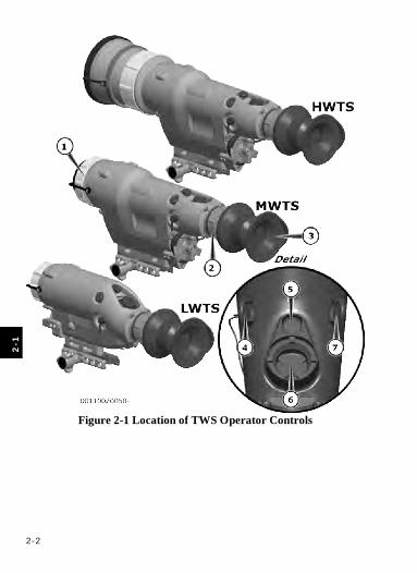
2-1.1.1 TWS CONTROLS TWS controls are common across all three variants. See Figure 2-1 for control locations, Table 2-1 for control descriptions and use, and Tables 2-2 & 2-3 for mapping of functions across TWS modes and states and description of TWS modes and states, respectively.
2-2
2
-1
Figure 2-1 Location of TWS Operator Controls
2-3
2-1
Table 2-1 Description & Use of TWS Operator Controls 1) Initial term is common name of control, bold font indicates marking adjacent to control on the TWS 2) Bold font indicates a prerequisite functional state condition for the operation 3) Italicized font indicates additional information of operational interest 4) Reticle moves in direction of impact movement (opposite of direction on display) KEY NAME1 FUNCTION OPERATION ACTION2 TWS REACTION3
1 Objective Focus Ring
←FAR/NEAR→
Adjusts focus of thermal scene.
Rotate Near/Far to adjust image focus.
Image focus varies with Operator input from 4m (LWTS/MWTS)/8m (HWTS) to Infinity (∞).
2 Diopter Ring
+2.. | 0 | ..-6
Adjusts focus of display (reticle and symbology).
Rotate -/+ to adjust display focus.
Display focus varies with Operator input between +2 to -6 Diopters.
Press Eyecup to transition from Standby to Operate.
The TWS will calibrate, the shutter will open, display will illuminate (Start-Up Screen will be displayed for < 3 seconds when transitioning from Standby) and image will be displayed. Video output from I/O Port.
3 Eyecup Standby
Override Switch
• Positions eye • Light security • Lens protection • Limited recoil
protection • STANDBY/
OPERATE toggle
• Display On/Off toggle
Release Eyecup to transition from Operate to Standby.
The TWS shutter will close when in Standby and Display will extinguish (< 3 sec delay). (ON Mode only- Standby is overridden in EMER and ZERO modes).
2-4
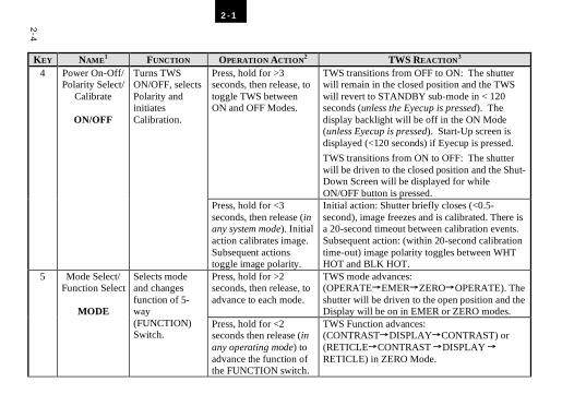
2-1
KEY NAME1 FUNCTION OPERATION ACTION2 TWS REACTION3 Press, hold for >3 seconds, then release, to toggle TWS between ON and OFF Modes.
TWS transitions from OFF to ON: The shutter will remain in the closed position and the TWS will revert to STANDBY sub-mode in < 120 seconds (unless the Eyecup is pressed). The display backlight will be off in the ON Mode (unless Eyecup is pressed). Start-Up screen is displayed (<120 seconds) if Eyecup is pressed.
TWS transitions from ON to OFF: The shutter will be driven to the closed position and the Shut-Down Screen will be displayed for while ON/OFF button is pressed.
4 Power On-Off/ Polarity Select/
Calibrate
ON/OFF
Turns TWS ON/OFF, selects Polarity and initiates Calibration.
Press, hold for <3 seconds, then release (in any system mode). Initial action calibrates image. Subsequent actions toggle image polarity.
Initial action: Shutter briefly closes (<0.5-second), image freezes and is calibrated. There is a 20-second timeout between calibration events. Subsequent action: (within 20-second calibration time-out) image polarity toggles between WHT HOT and BLK HOT.
Press, hold for >2 seconds, then release, to advance to each mode.
TWS mode advances: (OPERATE→EMER→ZERO→OPERATE). The shutter will be driven to the open position and the Display will be on in EMER or ZERO modes.
5 Mode Select/ Function Select
MODE
Selects mode and changes function of 5-way (FUNCTION) Switch.
Press, hold for <2 seconds then release (in any operating mode) to advance the function of the FUNCTION switch.
TWS Function advances: (CONTRAST→DISPLAY→CONTRAST) or (RETICLE→CONTRAST →DISPLAY → RETICLE) in ZERO Mode.
2-5
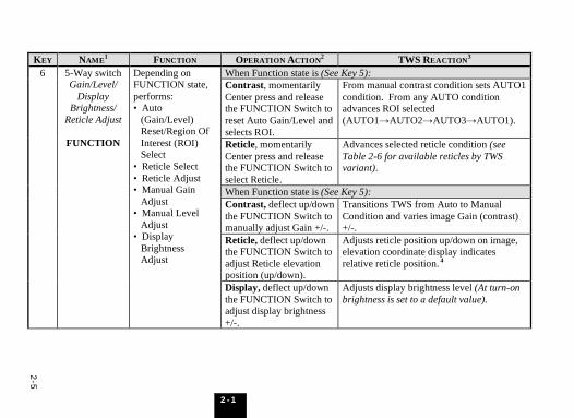
2-1
KEY NAME1 FUNCTION OPERATION ACTION2 TWS REACTION3 When Function state is (See Key 5): Contrast, momentarily Center press and release the FUNCTION Switch to reset Auto Gain/Level and selects ROI.
From manual contrast condition sets AUTO1 condition. From any AUTO condition advances ROI selected (AUTO1→AUTO2→AUTO3→AUTO1).
Reticle, momentarily Center press and release the FUNCTION Switch to select Reticle.
Advances selected reticle condition (see Table 2-6 for available reticles by TWS variant).
When Function state is (See Key 5): Contrast, deflect up/down the FUNCTION Switch to manually adjust Gain +/-.
Transitions TWS from Auto to Manual Condition and varies image Gain (contrast) +/-.
Reticle, deflect up/down the FUNCTION Switch to adjust Reticle elevation position (up/down).
Adjusts reticle position up/down on image, elevation coordinate display indicates relative reticle position. 4
6 5-Way switch Gain/Level/
Display Brightness/
Reticle Adjust
FUNCTION
Depending on FUNCTION state, performs: • Auto (Gain/Level) Reset/Region Of Interest (ROI) Select • Reticle Select • Reticle Adjust • Manual Gain Adjust • Manual Level Adjust • Display Brightness Adjust
Display, deflect up/down the FUNCTION Switch to adjust display brightness +/-.
Adjusts display brightness level (At turn-on brightness is set to a default value).
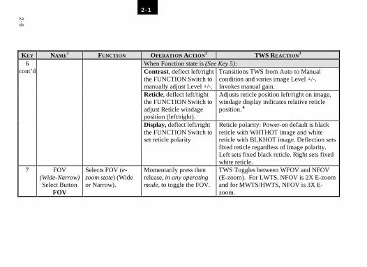
2-6
2-1
KEY NAME1 FUNCTION OPERATION ACTION2 TWS REACTION3
When Function state is (See Key 5): Contrast, deflect left/right the FUNCTION Switch to manually adjust Level +/-.
Transitions TWS from Auto to Manual condition and varies image Level +/-. Invokes manual gain.
Reticle, deflect left/right the FUNCTION Switch to adjust Reticle windage position (left/right).
Adjusts reticle position left/right on image, windage display indicates relative reticle position. 4
6 cont’d
Display, deflect left/right the FUNCTION Switch to set reticle polarity
Reticle polarity: Power-on default is black reticle with WHTHOT image and white reticle with BLKHOT image. Deflection sets fixed reticle regardless of image polarity. Left sets fixed black reticle. Right sets fixed white reticle.
7 FOV (Wide-Narrow) Select Button
FOV
Selects FOV (e-zoom state) (Wide or Narrow).
Momentarily press then release, in any operating mode, to toggle the FOV.
TWS Toggles between WFOV and NFOV (E-zoom). For LWTS, NFOV is 2X E-zoom and for MWTS/HWTS, NFOV is 3X E-zoom.

2-7
2-1
Table 2-2 TWS Modes, States & Functions Matrix Available Functions
Mode Sub-Mode State
Mod
e
Sele
ct
Eyec
up
Stan
dby
Ove
rrid
e
FOV
Pola
rity
/Cal
ibra
te
Man
ual
Gai
n/Le
vel
Aut
o R
eset
/ RO
I Se
lect
Ret
icle
Se
lect
/adj
ust
Disp
lay
Brig
htne
ss
Ret
icle
Po
lari
ty
OFF STANDBY * √
Contrast √ √ √ √ √ √ ON OPERATE Display √ √ √ √ √ √ Contrast √ √ √ √ √ EMERGENCY OPERATE Display √ √ √ √ √ Reticle √ √ √ √ Contrast √ √ √ √ √ ZERO OPERATE Display √ √ √ √ √
* To EMERGENCY and OFF Modes only.
2-8
2-1
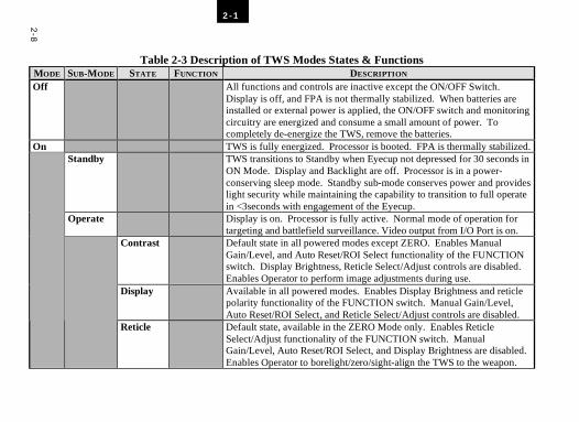
Table 2-3 Description of TWS Modes States & Functions MODE SUB-MODE STATE FUNCTION DESCRIPTION Off All functions and controls are inactive except the ON/OFF Switch.
Display is off, and FPA is not thermally stabilized. When batteries are installed or external power is applied, the ON/OFF switch and monitoring circuitry are energized and consume a small amount of power. To completely de-energize the TWS, remove the batteries.
On TWS is fully energized. Processor is booted. FPA is thermally stabilized. Standby TWS transitions to Standby when Eyecup not depressed for 30 seconds in
ON Mode. Display and Backlight are off. Processor is in a power-conserving sleep mode. Standby sub-mode conserves power and provides light security while maintaining the capability to transition to full operate in <3seconds with engagement of the Eyecup.
Operate Display is on. Processor is fully active. Normal mode of operation for targeting and battlefield surveillance. Video output from I/O Port is on.
Contrast Default state in all powered modes except ZERO. Enables Manual Gain/Level, and Auto Reset/ROI Select functionality of the FUNCTION switch. Display Brightness, Reticle Select/Adjust controls are disabled. Enables Operator to perform image adjustments during use.
Display Available in all powered modes. Enables Display Brightness and reticle polarity functionality of the FUNCTION switch. Manual Gain/Level, Auto Reset/ROI Select, and Reticle Select/Adjust controls are disabled.
Reticle Default state, available in the ZERO Mode only. Enables Reticle Select/Adjust functionality of the FUNCTION switch. Manual Gain/Level, Auto Reset/ROI Select, and Display Brightness are disabled. Enables Operator to borelight/zero/sight-align the TWS to the weapon.
2-9
2-1
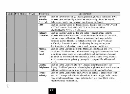
MODE SUB-MODE STATE FUNCTION DESCRIPTION Eyecup Standby Override
Enabled in ON Mode only. Pressing/releasing Eyecup transitions TWS between Operate/Standby sub-modes, respectively. Provides a quick, light secure, hands-free means of transitioning to Operate.
FOV Enabled in all powered modes and states. Toggles between WFOV and NFOV (E-zoom). For LWTS, NFOV is 2x E-zoom and for MWTS/HWTS, NFOV is 3 x E-zoom.
Polarity/ Calibrate
Enabled in all powered modes, and states. Toggles Image Polarity between White-Hot/Black-Hot. White-Hot is default turn-on condition. Initiates image calibration. Allows selection of the image polarity condition (White-Hot/Black-Hot) at any time and improves image uniformity. Provides a means of adjusting the image to improve discrimination of objects of interest under varying conditions.
Manual Gain/ Level
Enabled in the Contrast state only. Manually adjusts gain and level conditions. Enables manual adjustment of image gain (contrast) and level to optimize image under varying conditions and temperatures. Manual gain may be independently exercised (e.g. while in auto level). Manual level invokes manual gain (e.g., auto gain is not possible with manual level).
Display Brightness
Enabled in the Display State only. Adjusts Brightness level of the display. Enables Operator to select display brightness level to suit ambient lighting conditions. At turn-on, brightness is set to a default value.
Reticle Polarity
Enabled in the Display state only. Power-on default is black reticle with WHTHOT image and white reticle with BLKHOT image. Deflection sets fixed reticle regardless of image polarity. Left sets fixed black reticle. Right sets fixed white reticle.
2-1
0
2-1
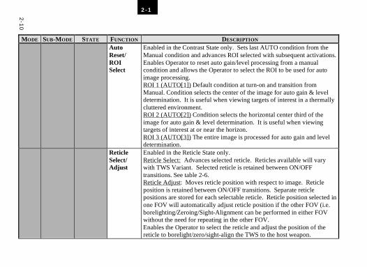
MODE SUB-MODE STATE FUNCTION DESCRIPTION Auto
Reset/ ROI Select
Enabled in the Contrast State only. Sets last AUTO condition from the Manual condition and advances ROI selected with subsequent activations. Enables Operator to reset auto gain/level processing from a manual condition and allows the Operator to select the ROI to be used for auto image processing. ROI 1 (AUTO[1]) Default condition at turn-on and transition from Manual. Condition selects the center of the image for auto gain & level determination. It is useful when viewing targets of interest in a thermally cluttered environment. ROI 2 (AUTO[2]) Condition selects the horizontal center third of the image for auto gain & level determination. It is useful when viewing targets of interest at or near the horizon. ROI 3 (AUTO[3]) The entire image is processed for auto gain and level determination.
Reticle Select/ Adjust
Enabled in the Reticle State only. Reticle Select: Advances selected reticle. Reticles available will vary with TWS Variant. Selected reticle is retained between ON/OFF transitions. See table 2-6. Reticle Adjust: Moves reticle position with respect to image. Reticle position is retained between ON/OFF transitions. Separate reticle positions are stored for each selectable reticle. Reticle position selected in one FOV will automatically adjust reticle position if the other FOV (i.e. borelighting/Zeroing/Sight-Alignment can be performed in either FOV without the need for repeating in the other FOV. Enables the Operator to select the reticle and adjust the position of the reticle to borelight/zero/sight-align the TWS to the host weapon.
2-1
1
2-1
MODE SUB-
MODE STATE FUNCTION DESCRIPTION
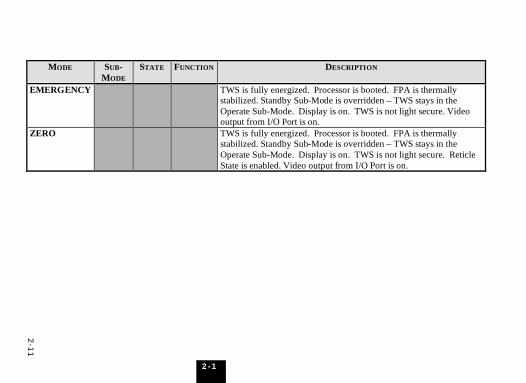
EMERGENCY TWS is fully energized. Processor is booted. FPA is thermally stabilized. Standby Sub-Mode is overridden – TWS stays in the Operate Sub-Mode. Display is on. TWS is not light secure. Video output from I/O Port is on.
ZERO TWS is fully energized. Processor is booted. FPA is thermally stabilized. Standby Sub-Mode is overridden – TWS stays in the Operate Sub-Mode. Display is on. TWS is not light secure. Reticle State is enabled. Video output from I/O Port is on.
2-12
2
-1
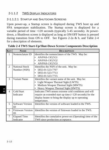
2-1.1.2 TWS DISPLAY INDICATORS
2-1.1.2.1 STARTUP AND SHUTDOWN SCREENS Upon power-up, a Startup screen is displayed during TWS boot up and FPA temperature stabilization. The Startup screen is displayed for a variable period of time <120 seconds (typically 5-45 seconds). At power-down, a Shutdown screen is displayed as long as ON/OFF button is pressed during transition from ON to OFF. See Figures 2-2a & b, and Table 2-4 for a description of elements. Table 2-4 TWS Start-Up/Shut-Down Screen Components Description
KEY NAME DESCRIPTION 1 Nomenclature ID Identifies the nomenclature of the TWS. May be:
• AN/PAS-13C(V)1 • AN/PAS-13C(V)2 • AN/PAS-13C(V)3
2 National Stock Number (NSN)
Identifies the NSN of the unit. May be: • 5855-01-523-7707 • 5855-01-523-7713 • 5855-01-523-7715
3 Variant Name Identifies the variant name of the unit. May be: • Light Weapon Thermal Sight (LWTS) • Medium Weapon Thermal Sight (MWTS) • Heavy Weapon Thermal Sight (HWTS)
4 Cold Start Indicator
Indicates TWS senses extreme cold conditions and will require an extended start up time (<120 seconds) for the display heater to bring the display up to operating temperature.
5 Software Version ID
Identifies the version of software loaded in the TWS.
6 Firmware Version ID
Identifies the version of firmware loaded in the TWS.
7 Elapsed Time Indicator
Identifies the cumulative power-on (Operating) time of the TWS since production acceptance.
2-13
2-1
Figure 2-2a TWS Startup Screen
Figure 2-2b TWS Shutdown Screen
2-14
2
-1
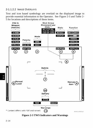
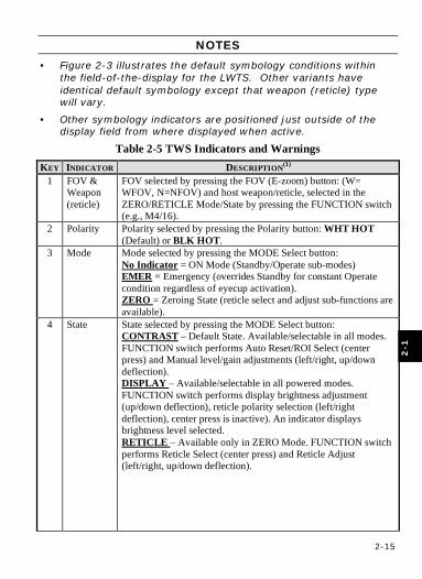
2-1.1.2.2 IMAGE OVERLAYS Text and icon based symbology are overlaid on the displayed image to provide essential information to the Operator. See Figure 2-3 and Table 2-5 for locations and descriptions of these items.
Figure 2-3 TWS Indicators and Warnings
2-15
2-1
NOTES
• Figure 2-3 illustrates the default symbology conditions within the field-of-the-display for the LWTS. Other variants have identical default symbology except that weapon (reticle) type will vary.
• Other symbology indicators are positioned just outside of the display field from where displayed when active.
Table 2-5 TWS Indicators and Warnings KEY INDICATOR DESCRIPTION(1)
1 FOV & Weapon (reticle)
FOV selected by pressing the FOV (E-zoom) button: (W= WFOV, N=NFOV) and host weapon/reticle, selected in the ZERO/RETICLE Mode/State by pressing the FUNCTION switch (e.g., M4/16).
2 Polarity Polarity selected by pressing the Polarity button: WHT HOT (Default) or BLK HOT.
3 Mode Mode selected by pressing the MODE Select button: No Indicator = ON Mode (Standby/Operate sub-modes) EMER = Emergency (overrides Standby for constant Operate condition regardless of eyecup activation). ZERO = Zeroing State (reticle select and adjust sub-functions are available).
4 State State selected by pressing the MODE Select button: CONTRAST – Default State. Available/selectable in all modes. FUNCTION switch performs Auto Reset/ROI Select (center press) and Manual level/gain adjustments (left/right, up/down deflection). DISPLAY – Available/selectable in all powered modes. FUNCTION switch performs display brightness adjustment (up/down deflection), reticle polarity selection (left/right deflection), center press is inactive). An indicator displays brightness level selected. RETICLE – Available only in ZERO Mode. FUNCTION switch performs Reticle Select (center press) and Reticle Adjust (left/right, up/down deflection).
2-16
2
-1
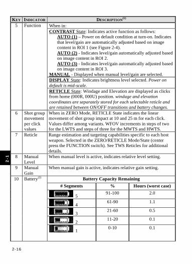
KEY INDICATOR DESCRIPTION(1) When in: CONTRAST State: Indicates active function as follows:
AUTO (1) – Power on default condition at turn-on. Indicates that level/gain are automatically adjusted based on image content in ROI 1 (see Figure 2-4). AUTO (2) - Indicates level/gain automatically adjusted based on image content in ROI 2. AUTO (3) - Indicates level/gain automatically adjusted based on image content in ROI 3.
MANUAL - Displayed when manual level/gain are selected. DISPLAY State: Indicates brightness level selected. Power on default is mid-scale.
5 Function
RETICLE State: Windage and Elevation are displayed as clicks from home (000R, 000U) position. windage and elevation coordinates are separately stored for each selectable reticle and are retained between ON/OFF transitions and battery changes.
6 Shot group movement per click values
When in ZERO Mode, RETICLE State indicates the linear movement of shot group impact at 10 and 25 m for each click. Values differ among variants. WFOV increments in steps of two for the LWTS and steps of three for the MWTS and HWTS.
7 Reticle Range estimation and targeting capabilities specific to each host weapon. Selected in the ZERO/RETICLE Mode/State (center press the FUNCTION switch). See TWS Reticles for additional details.
8 Manual Level
When manual level is active, indicates relative level setting.
9 Manual Gain
When manual gain is active, indicates relative gain setting.
Battery Capacity Remaining # Segments % Hours (worst case)
5 91-100 2.0
4 61-90 1.1
3 21-60 0.5
2 11-20 0.1
10 Battery(2) 1 0-10 0.1
2-17
2-1
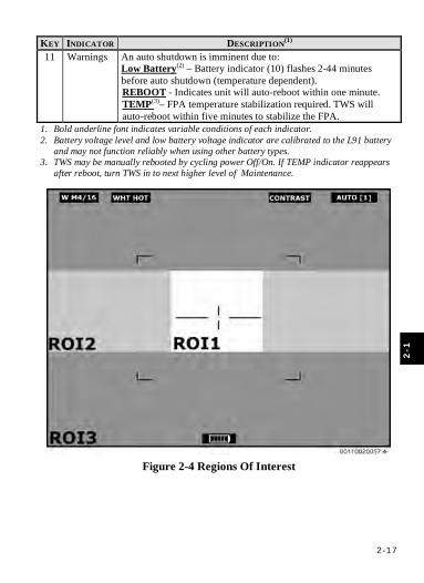
KEY INDICATOR DESCRIPTION(1) 11 Warnings An auto shutdown is imminent due to:
Low Battery(2) – Battery indicator (10) flashes 2-44 minutes before auto shutdown (temperature dependent). REBOOT - Indicates unit will auto-reboot within one minute. TEMP(3)– FPA temperature stabilization required. TWS will auto-reboot within five minutes to stabilize the FPA.
1. Bold underline font indicates variable conditions of each indicator. 2. Battery voltage level and low battery voltage indicator are calibrated to the L91 battery
and may not function reliably when using other battery types. 3. TWS may be manually rebooted by cycling power Off/On. If TEMP indicator reappears
after reboot, turn TWS in to next higher level of Maintenance.
Figure 2-4 Regions Of Interest
2-18
2
-1
2-1.1.3 TWS RETICLES The TWS uses reticles that are electronically (digitally) overlaid/embedded in the thermal image to provide targeting, range estimation, and angular measurement functions.
2-1.1.3.1 COMMON RETICLE INDICATORS
2-1.1.3.1.1 Zeroing Aim Line and Aim Point. The two longest horizontal lines to the left and right of the zeroing aim point are referred to as the zeroing aim line. The zeroing aim line is used on the M16, M136, M240, M249, M2, and MK19. The zeroing aim lines serve two purposes: 1) For reticles with multiple aim points, they indicate which aim point to
use when zeroing the TWS; 2) Serve as a means of measuring angles for combat preparations,
directing fire, or range estimation. Angular scale dimensions are defined for each reticle in subsequent paragraphs.
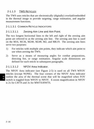
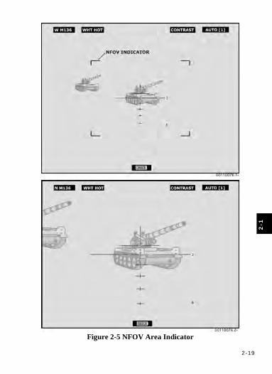
2-1.1.3.1.2 NFOV Area Indicator. The NFOV Area indicator (see Figure 2-5) is used on all TWS WFOV reticles (except NONE). The four corners of the NFOV Area indicator outline the area of the thermal scene that will be magnified when FOV switch is toggled from WFOV to NFOV. E-zoom magnification in NFOV is 2x for LWTS and 3x for MWTS/HWTS.
2-19
2-1
Figure 2-5 NFOV Area Indicator
2-20
2
-1
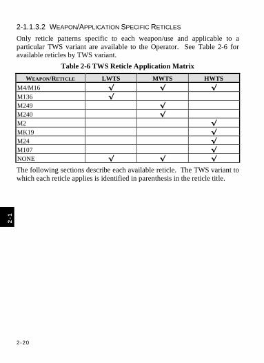
2-1.1.3.2 WEAPON/APPLICATION SPECIFIC RETICLES Only reticle patterns specific to each weapon/use and applicable to a particular TWS variant are available to the Operator. See Table 2-6 for available reticles by TWS variant.
Table 2-6 TWS Reticle Application Matrix
WEAPON/RETICLE LWTS MWTS HWTS M4/M16 √ √ √ M136 √ M249 √ M240 √ M2 √ MK19 √ M24 √ M107 √ NONE √ √ √
The following sections describe each available reticle. The TWS variant to which each reticle applies is identified in parenthesis in the reticle title.
2-21
2-1
NOTES • Reticle illustrations herein are intended to illustrate reticle
features and usage and may not be to scale. • Reticle positions illustrated may vary from actual display. • Reticle positions will vary as a result of reticle coordinates set
during zeroing or sight alignment. • The “home” (000R 000U) reticle coordinate position in the
display will vary from reticle to reticle as a result of weapon specific calibrations applied separately to each reticle by the manufacturer.
• The “home” (000R 000U) reticle coordinate position in the display will vary from TWS to TWS as a result of TWS specific calibrations applied by the manufacturer.
• Differences in displayed reticle position from those illustrated is acceptable and is not cause for TWS rejection or maintenance action.
2-22
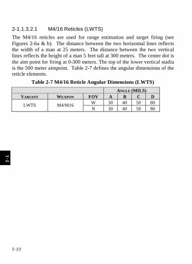
2
-1
2-1.1.3.2.1 M4/16 Reticles (LWTS) The M4/16 reticles are used for range estimation and target firing (see Figures 2-6a & b). The distance between the two horizontal lines reflects the width of a man at 25 meters. The distance between the two vertical lines reflects the height of a man 5 feet tall at 300 meters. The center dot is the aim point for firing at 0-300 meters. The top of the lower vertical stadia is the 500 meter aimpoint. Table 2-7 defines the angular dimensions of the reticle elements.
Table 2-7 M4/16 Reticle Angular Dimensions (LWTS) ANGLE (MILS)
VARIANT WEAPON FOV A B C D W 30 40 50 80 LWTS M4/M16 N 30 40 50 80

2-23
2-1
Figure 2-6a M4/M16 Reticle (LWTS-WFOV)
Figure 2-6b M4/M16 Reticle (LWTS-NFOV)

2-24
2
-1
2-1.1.3.2.2 M136 Reticle (LWTS) The M136 reticle provides multiple crosshairs used for range estimation and target firing (see Figures 2-7a & b). Each crosshair is used at a different range. The range at which to use a specific crosshair is indicated on the side of the crosshair, in the hundreds digit, in meters (example: 6 = 600 meters). Each crosshair is separated by a range of 100 meters. The vertical line of a crosshair reflects the height of a man 5 feet tall at the indicated range. The horizontal line of a crosshair reflects the width of a 10-foot tank at the indicated range. The firing aim point of each crosshair is the point of intersection of the vertical and horizontal lines. Table 2-8 defines the angular dimensions of the reticle elements.
Table 2-8 M136 Reticle Angular Dimensions ANGLE (MILS)
VARIANT WEAPON FOV A B C D W 30 40 50 80 LWTS M136 N 30 40 50 80
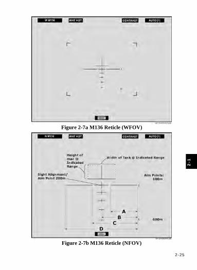
2-25
2-1
Figure 2-7a M136 Reticle (WFOV)
Figure 2-7b M136 Reticle (NFOV)

2-26
2
-1
2-1.1.3.2.3 NONE Reticle (LWTS) The NONE reticle provides a clutter-free image area when range estimation, angular measurement and targeting are not required except NFOV Indicator will be present in WFOV (see Figures 2-8a & b).
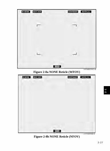
2-27
2-1
Figure 2-8a NONE Reticle (WFOV)
Figure 2-8b NONE Reticle (NFOV)
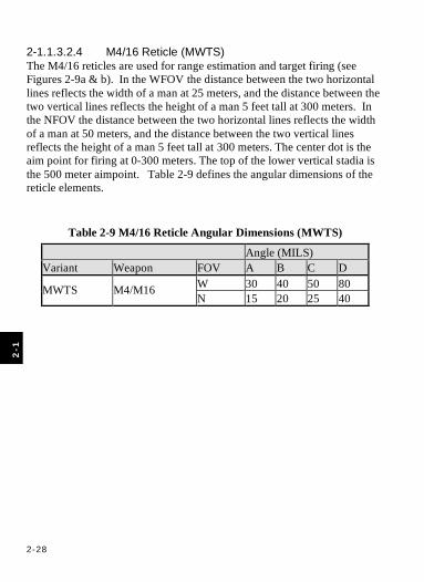
2-28
2
-1
2-1.1.3.2.4 M4/16 Reticle (MWTS) The M4/16 reticles are used for range estimation and target firing (see Figures 2-9a & b). In the WFOV the distance between the two horizontal lines reflects the width of a man at 25 meters, and the distance between the two vertical lines reflects the height of a man 5 feet tall at 300 meters. In the NFOV the distance between the two horizontal lines reflects the width of a man at 50 meters, and the distance between the two vertical lines reflects the height of a man 5 feet tall at 300 meters. The center dot is the aim point for firing at 0-300 meters. The top of the lower vertical stadia is the 500 meter aimpoint. Table 2-9 defines the angular dimensions of the reticle elements.
Table 2-9 M4/16 Reticle Angular Dimensions (MWTS)
Angle (MILS) Variant Weapon FOV A B C D
W 30 40 50 80 MWTS M4/M16 N 15 20 25 40
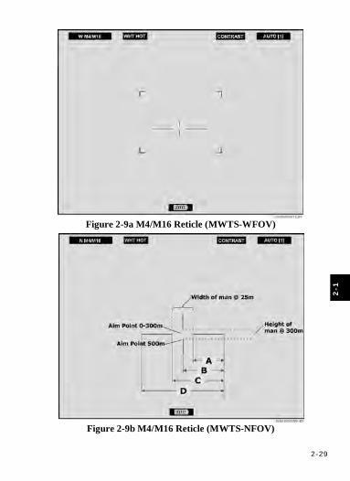
2-29
2-1
Figure 2-9a M4/M16 Reticle (MWTS-WFOV)
Figure 2-9b M4/M16 Reticle (MWTS-NFOV)
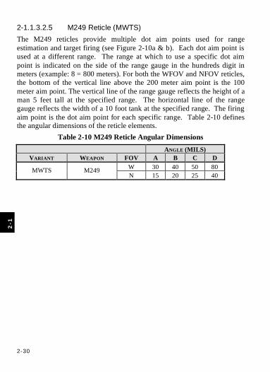
2-30
2
-1
2-1.1.3.2.5 M249 Reticle (MWTS) The M249 reticles provide multiple dot aim points used for range estimation and target firing (see Figure 2-10a & b). Each dot aim point is used at a different range. The range at which to use a specific dot aim point is indicated on the side of the range gauge in the hundreds digit in meters (example: 8 = 800 meters). For both the WFOV and NFOV reticles, the bottom of the vertical line above the 200 meter aim point is the 100 meter aim point. The vertical line of the range gauge reflects the height of a man 5 feet tall at the specified range. The horizontal line of the range gauge reflects the width of a 10 foot tank at the specified range. The firing aim point is the dot aim point for each specific range. Table 2-10 defines the angular dimensions of the reticle elements.
Table 2-10 M249 Reticle Angular Dimensions ANGLE (MILS)
VARIANT WEAPON FOV A B C D W 30 40 50 80 MWTS M249 N 15 20 25 40
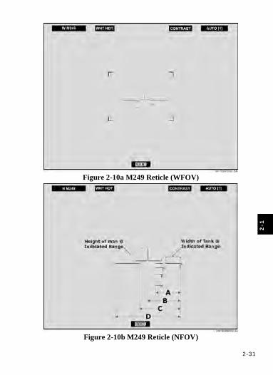
2-31
2-1
Figure 2-10a M249 Reticle (WFOV)
Figure 2-10b M249 Reticle (NFOV)
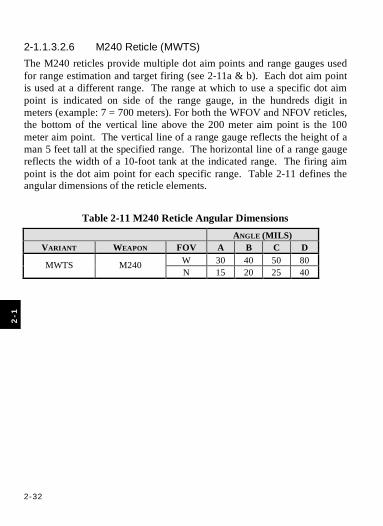
2-32
2
-1
2-1.1.3.2.6 M240 Reticle (MWTS) The M240 reticles provide multiple dot aim points and range gauges used for range estimation and target firing (see 2-11a & b). Each dot aim point is used at a different range. The range at which to use a specific dot aim point is indicated on side of the range gauge, in the hundreds digit in meters (example: 7 = 700 meters). For both the WFOV and NFOV reticles, the bottom of the vertical line above the 200 meter aim point is the 100 meter aim point. The vertical line of a range gauge reflects the height of a man 5 feet tall at the specified range. The horizontal line of a range gauge reflects the width of a 10-foot tank at the indicated range. The firing aim point is the dot aim point for each specific range. Table 2-11 defines the angular dimensions of the reticle elements.
Table 2-11 M240 Reticle Angular Dimensions ANGLE (MILS)
VARIANT WEAPON FOV A B C D W 30 40 50 80 MWTS M240 N 15 20 25 40
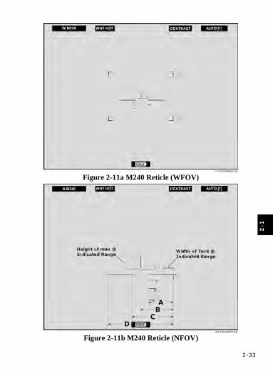
2-33
2-1
Figure 2-11a M240 Reticle (WFOV)
Figure 2-11b M240 Reticle (NFOV)
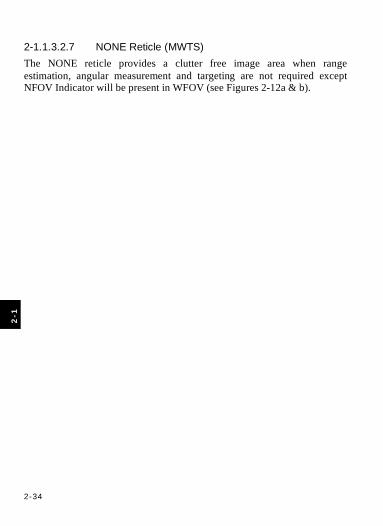
2-34
2
-1
2-1.1.3.2.7 NONE Reticle (MWTS) The NONE reticle provides a clutter free image area when range estimation, angular measurement and targeting are not required except NFOV Indicator will be present in WFOV (see Figures 2-12a & b).

2-35
2-1
Figure 2-12a NONE Reticle (WFOV)
Figure 2-12b NONE Reticle (NFOV)
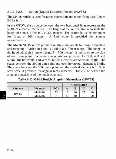
2-36
2
-1
2-1.1.3.2.8 M4/16 (Squad Leaders) Reticle (HWTS) The M4/16 reticle is used for range estimation and target firing (see Figure 2-13a & b). In the WFOV, the distance between the two horizontal lines represents the width of a man at 25 meters. The length of the vertical line represents the height of a man, 5 feet tall, at 300 meters. The center dot is the aim point for firing at 300 meters. A 5mil scale is provided for angular measurements. The M4/16 NFOV reticle provides multiple aim points for range estimation and targeting. Each aim point is used at a different range. The range, in the hundreds digit in meters (e.g., 5 = 500 meters), is indicated to the side of each aim point. Separate aim points are provided for 300, 400 and 500m. The horizontal and vertical reticle elements are 5mils in length. The space between the 300 m aim point and each horizontal element is 5mils. The space between the 300m aim point and the vertical element is 1mil. A 5mil scale is provided for angular measurements. Table 2-12 defines the angular dimensions of the reticle elements.
Table 2-12 M4/16 Reticle Angular Dimensions (HWTS) ANGLE (MILS)
VARIANT WEAPON FOV A B C D M4/M16 W 15 20 25 40 HWTS M4/M16 N 5 10 15 20

2-37
2-1
Figure 2-13a M4/16 Reticle (HWTS-WFOV)
Figure 2-13b M4/16 Reticle (HWTS-NFOV)
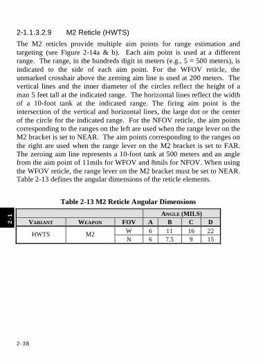
2-38
2
-1
2-1.1.3.2.9 M2 Reticle (HWTS) The M2 reticles provide multiple aim points for range estimation and targeting (see Figure 2-14a & b). Each aim point is used at a different range. The range, in the hundreds digit in meters (e.g., 5 = 500 meters), is indicated to the side of each aim point. For the WFOV reticle, the unmarked crosshair above the zeroing aim line is used at 200 meters. The vertical lines and the inner diameter of the circles reflect the height of a man 5 feet tall at the indicated range. The horizontal lines reflect the width of a 10-foot tank at the indicated range. The firing aim point is the intersection of the vertical and horizontal lines, the large dot or the center of the circle for the indicated range. For the NFOV reticle, the aim points corresponding to the ranges on the left are used when the range lever on the M2 bracket is set to NEAR. The aim points corresponding to the ranges on the right are used when the range lever on the M2 bracket is set to FAR. The zeroing aim line represents a 10-foot tank at 500 meters and an angle from the aim point of 11mils for WFOV and 8mils for NFOV. When using the WFOV reticle, the range lever on the M2 bracket must be set to NEAR. Table 2-13 defines the angular dimensions of the reticle elements.
Table 2-13 M2 Reticle Angular Dimensions ANGLE (MILS)
VARIANT WEAPON FOV A B C D W 6 11 16 22 HWTS M2 N 6 7.5 9 15

2-39
2-1
Figure 2-14a M2 Reticle (WFOV)
Figure 2-14b M2 Reticle (NFOV)
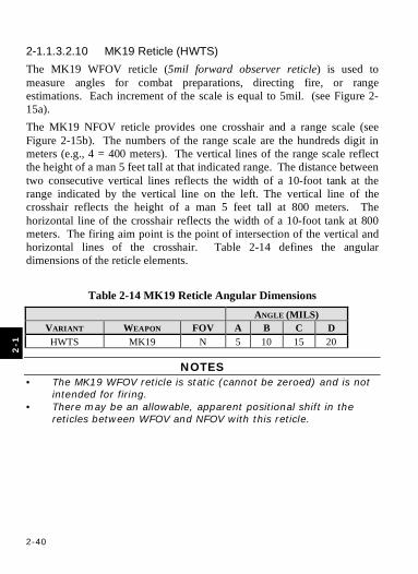
2-40
2
-1
2-1.1.3.2.10 MK19 Reticle (HWTS) The MK19 WFOV reticle (5mil forward observer reticle) is used to measure angles for combat preparations, directing fire, or range estimations. Each increment of the scale is equal to 5mil. (see Figure 2-15a). The MK19 NFOV reticle provides one crosshair and a range scale (see Figure 2-15b). The numbers of the range scale are the hundreds digit in meters (e.g., 4 = 400 meters). The vertical lines of the range scale reflect the height of a man 5 feet tall at that indicated range. The distance between two consecutive vertical lines reflects the width of a 10-foot tank at the range indicated by the vertical line on the left. The vertical line of the crosshair reflects the height of a man 5 feet tall at 800 meters. The horizontal line of the crosshair reflects the width of a 10-foot tank at 800 meters. The firing aim point is the point of intersection of the vertical and horizontal lines of the crosshair. Table 2-14 defines the angular dimensions of the reticle elements.
Table 2-14 MK19 Reticle Angular Dimensions ANGLE (MILS)
VARIANT WEAPON FOV A B C D HWTS MK19 N 5 10 15 20
NOTES • The MK19 WFOV reticle is static (cannot be zeroed) and is not
intended for firing. • There may be an allowable, apparent positional shift in the
reticles between WFOV and NFOV with this reticle.
2-41
2-1
Figure 2-15a MK19 Reticle (WFOV)
Figure 2-15b MK19 Reticle (NFOV)
2-42
2
-1
2-1.1.3.2.11 M24 Reticle (HWTS) The M24 WFOV reticle (5mil forward observer reticle) is used to measure angles for combat preparations, directing fire, or range estimations. Each increment of the scale is equal to 5mil (see Figure 2-16a). The M24 NFOV reticle provides aim points for various ranges and an angular scale (see Figure 2-16b). The angular scale is used for combat preparations, directing fire, or range estimations. The aim points are the center of the crosshairs for each indicated range (includes compensation for normal drift of the round). The horizontal line of dots at the odd ranges and the vertical scale are mil dot scales. The range, in the hundreds digit, in meters (e.g., 4 = 400 meters), is indicated to the side of each aim point. Table 2-15 defines the angular dimensions of the reticle elements.
Table 2-15 M24 Reticle Angular Dimensions ANGLE (MILS)
VARIANT WEAPON FOV A B C D HWTS M24 N 4 5 6 10
NOTES • The M24 WFOV reticle is static (cannot be zeroed) and is not
intended for firing. • There may be an allowable, apparent positional shift in the
reticles between WFOV and NFOV with this reticle.
2-43
2-1
Figure 2-16a M24 Reticle (WFOV)
Figure 2-16b M24 Reticle (NFOV)
2-44
2
-1
2-1.1.3.2.12 M107 Reticle (HWTS) The M107 WFOV reticle (5mil forward observer reticle) is used to measure angles for combat preparations, directing fire, or range estimations. Each increment of the scale is equal to 5mil (see Figure 2-17a). The M107 NFOV reticle provides aim points for various ranges and an angular scale (see Figure 2-17b). The angular scale is used for combat preparations, directing fire, or range estimations. The aim points are the center of the crosshairs for each indicated range (includes compensation for normal drift of the round). The horizontal line of dots at the odd ranges and the vertical scale are mil dot scales. The range, in the hundreds digit, in meters (e.g., 5 = 500 meters), is indicated to the side of each aim point. Table 2-16 defines the angular dimensions of the reticle elements.
Table 2-16 M107 Reticle Angular Dimensions ANGLE (MILS)
VARIANT WEAPON FOV A B C D HWTS M107 N 4 5 6 10
NOTES • The M107 WFOV reticle is static (cannot be zeroed) and is not
intended for firing. • There may be an allowable, apparent positional shift in the
reticles between WFOV and NFOV with this reticle.
2-45
2-1
Figure 2-17a M107 Reticle (WFOV)
Figure 2-17b M107 Reticle (NFOV)

2-46
2
-1
2-1.1.3.2.13 NONE Reticle (HWTS) The NONE reticle provides a clutter-free image area when range estimation, angular measurement and targeting are not required except NFOV Indicator will be present in WFOV (see Figures 2-18a & b).
2-47
2-1
Figure 2-18a NONE Reticle (WFOV)
Figure 2-18b NONE Reticle (NFOV)
2-48
SECTION 2 PREVENTIVE MAINTENANCE CHECKS AND SERVICES (PMCS)
2-2.1 INTRODUCTION TO PMCS TABLE
2-2.1.1 GENERAL Table 2-17 (TWS PMCS table) has been provided so you can keep your equipment in good operating condition and ready for its primary mission.
2-2.1.2 WARNINGS AND CAUTIONS Always observe the WARNINGS and CAUTIONS appearing in your PMCS table. WARNINGS and CAUTIONS appear before applicable procedures. You must observe these WARNINGS and CAUTIONS to prevent serious injury to yourself and others or prevent your equipment from being damaged.
2-2.1.3 EXPLANATION OF TABLE ENTRIES
2-2.1.3.1 ITEM NUMBER COLUMN Numbers in this column are for reference. When completing DA Form 5988-E (Equipment Inspection and Maintenance Worksheet), include the item number for the check/service indicating a fault. Item numbers also appear in the order that you must do checks and service for the intervals listed.
2-2.1.3.2 INTERVAL COLUMN This column tells you when you must do the procedure in the procedure column. BEFORE procedures must be done before you operate or use the equipment for its intended mission. DURING procedures must be done during the time you are operating or using the equipment for its intended mission. AFTER procedures must be done immediately after you have operated or used the equipment.
2-2.1.3.3 LOCATION ITEM TO CHECK/SERVICE COLUMN This column provides the location and the item to be checked or serviced.
2
-2
2-49
2-1
2-2.1.3.4 PROCEDURE COLUMN This column gives the procedure you must do to check or service the item listed in the Check/Service column to know if the equipment is ready or available for its intended mission or for operation. You must do the procedure at the time stated in the interval column.
2-2.1.3.5 NOT FULLY MISSION CAPABLE IF: COLUMN If you perform PMCS that show faults listed in this column, do not operate the TWS. Any listing in this column requires return to a higher level of maintenance.
2-2.2 PMCS TABLE To perform PMCS, follow the Preventive Maintenance Checks and Services for TWS (Table 2-17).
WARNING Do not touch, ingest, or inhale particles of a broken objective
lens. Lens contains germanium which is slightly toxic if ingested or inhaled. Fragments may be sharp enough to cut personnel if
touched.
CAUTION Failure to push when rotating or over-rotating battery cassette
latch may result in damage to Battery Cassette
2-2

2-5
0
2-2
Table 2-17 TWS PMCS
ITEM NO.
INTERVAL LOCATION ITEM TO CHECK/SERVICE
PROCEDURE NOT FULLY MISSION CAPABLE IF:
(a) Inspect TWS components per Appendix B and for presence of QRC.
(a) TWS components are missing or damaged.
1 Before TWS Components
(b) As required, clean TWS components per Chapter 3, to include CLP that may be on any sight component.
2 Before Controls Inspect controls (Figure 2-1 and Table 2-1 for location of controls).
Controls are loose or damaged. Controls or parts of controls (e.g., Button Caps) are missing.
(a) Inspect, open Objective Lens Cap.
(a) Objective Lens Cap is damaged or missing.
(b) Inspect Objective Lens. If needed clean Objective Lens per ¶3-2.3.
(b) Objective Lens is cracked or chipped.
(c) Turn Objective Focus Ring. (c) Objective Focus Ring does not turn smoothly from stop to stop.
3
Before Objective Lens and Lens Cap
(d) Close Objective Lens Cap. (d) Objective Lens Cap does not close.
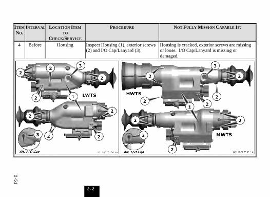
2-5
1
2-2
ITEM NO.
INTERVAL LOCATION ITEM TO
CHECK/SERVICE
PROCEDURE NOT FULLY MISSION CAPABLE IF:
4 Before Housing Inspect Housing (1), exterior screws (2) and I/O Cap/Lanyard (3).
Housing is cracked, exterior screws are missing or loose. I/O Cap/Lanyard is missing or damaged.

2-5
2
2-2
ITEM NO.
INTERVAL LOCATION ITEM TO
CHECK/SERVICE
PROCEDURE NOT FULLY MISSION CAPABLE IF:
(a) Remove Battery Cassette (1). (a) Battery Cassette cannot be removed. (b) Inspect Barrel Hooks (2), battery
contacts (3), Battery Compartment Seal (4) and compartment interior (5).
(b) Barrel Hooks, contacts, or Battery Compartment Seal, are damaged/ missing. Contacts are corroded. Battery Compartment cracked/broken.
5 Before Battery Compartment
(c) Clean Battery Compartment and contacts per ¶ 3-2.5.
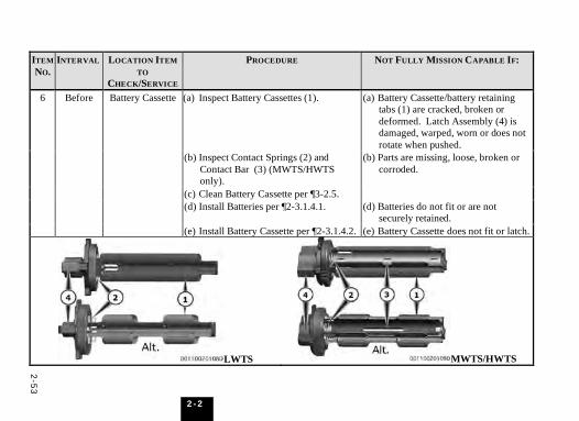
2-5
3
2-2
ITEM NO.
INTERVAL LOCATION ITEM TO
CHECK/SERVICE
PROCEDURE NOT FULLY MISSION CAPABLE IF:
(a) Inspect Battery Cassettes (1). (a) Battery Cassette/battery retaining tabs (1) are cracked, broken or deformed. Latch Assembly (4) is damaged, warped, worn or does not rotate when pushed.
(b) Inspect Contact Springs (2) and Contact Bar (3) (MWTS/HWTS only).
(b) Parts are missing, loose, broken or corroded.
(c) Clean Battery Cassette per ¶3-2.5. (c) (d) Install Batteries per ¶2-3.1.4.1. (d) Batteries do not fit or are not
securely retained.
6 Before Battery Cassette
(e) Install Battery Cassette per ¶2-3.1.4.2. (e) Battery Cassette does not fit or latch.
LWTS MWTS/HWTS
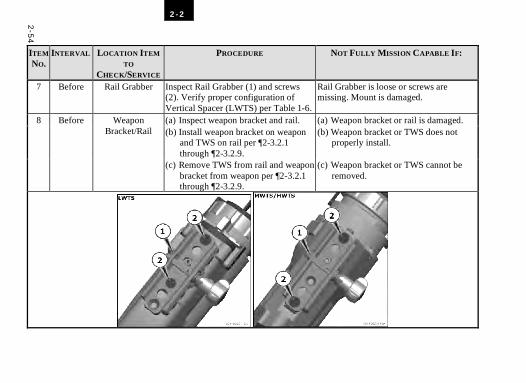
2-5
4
2-2
ITEM NO.
INTERVAL LOCATION ITEM TO
CHECK/SERVICE
PROCEDURE NOT FULLY MISSION CAPABLE IF:
7 Before Rail Grabber Inspect Rail Grabber (1) and screws (2). Verify proper configuration of Vertical Spacer (LWTS) per Table 1-6.
Rail Grabber is loose or screws are missing. Mount is damaged.
(a) Inspect weapon bracket and rail. (a) Weapon bracket or rail is damaged. (b) Install weapon bracket on weapon
and TWS on rail per ¶2-3.2.1 through ¶2-3.2.9.
(b) Weapon bracket or TWS does not properly install.
8 Before Weapon Bracket/Rail
(c) Remove TWS from rail and weapon bracket from weapon per ¶2-3.2.1 through ¶2-3.2.9.
(c) Weapon bracket or TWS cannot be removed.
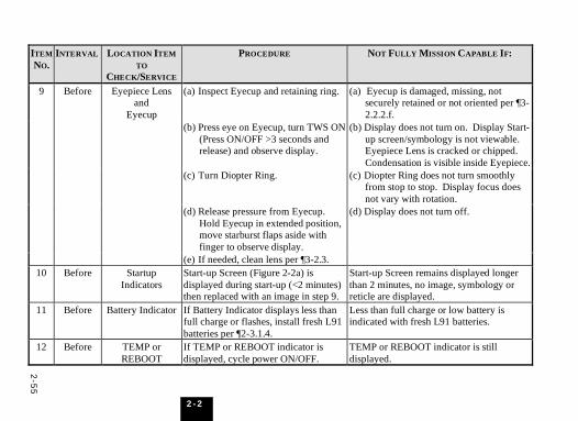
2-5
5
2-2
ITEM NO.
INTERVAL LOCATION ITEM TO
CHECK/SERVICE
PROCEDURE NOT FULLY MISSION CAPABLE IF:
(a) Inspect Eyecup and retaining ring. (a) Eyecup is damaged, missing, not securely retained or not oriented per ¶3-2.2.2.f.
(b) Press eye on Eyecup, turn TWS ON (Press ON/OFF >3 seconds and release) and observe display.
(b) Display does not turn on. Display Start-up screen/symbology is not viewable. Eyepiece Lens is cracked or chipped. Condensation is visible inside Eyepiece.
(c) Turn Diopter Ring. (c) Diopter Ring does not turn smoothly from stop to stop. Display focus does not vary with rotation.
(d) Release pressure from Eyecup. Hold Eyecup in extended position, move starburst flaps aside with finger to observe display.
(d) Display does not turn off.
9 Before Eyepiece Lens and
Eyecup
(e) If needed, clean lens per ¶3-2.3. (e) 10 Before Startup
Indicators Start-up Screen (Figure 2-2a) is displayed during start-up (<2 minutes) then replaced with an image in step 9.
Start-up Screen remains displayed longer than 2 minutes, no image, symbology or reticle are displayed.
11 Before Battery Indicator If Battery Indicator displays less than full charge or flashes, install fresh L91 batteries per ¶2-3.1.4.
Less than full charge or low battery is indicated with fresh L91 batteries.
12 Before TEMP or REBOOT
If TEMP or REBOOT indicator is displayed, cycle power ON/OFF.
TEMP or REBOOT indicator is still displayed.
2-5
6
2-2
ITEM NO.
INTERVAL LOCATION ITEM TO
CHECK/SERVICE
PROCEDURE NOT FULLY MISSION CAPABLE IF:
a. View Display. (a) Display is not visible. Display jitters or jumps.
b. Looking at Display, adjust Diopter Ring on Eyepiece for sharp focus of reticle and status indicators.
(b) Reticle and indicators are not visible. Reticle and indicators will not sharply focus.
c. Open Objective Lens Cap and check for thermal scene.
(c) Thermal scene is not visible. Display has dead rows, columns, pixels, or fixed pattern noise that adversely affects ability to acquire or engage a target.
d. Activate FOV switch once (to NFOV), check reticle and indicator.
(d) FOV indicator does not change to N. Reticle does not change. Magnification of thermal scene does not change. Reticle features are incorrect.
13 Before TWS Display Controls and
Indicators
e. Activate FOV switch once (to WFOV), check reticle and indicator.
(e) FOV indicator does not change to W. Reticle does not change. Magnification of thermal scene does not change. Reticle features are incorrect.
2-5
7
2-2
ITEM NO.
INTERVAL LOCATION ITEM TO
CHECK/SERVICE
PROCEDURE NOT FULLY MISSION CAPABLE IF:
f. View object at approximately 10m and adjust Objective Focus Ring.
(f) Objective Lens will not sharply focus on object.
g. View a distant object and adjust Objective Focus Ring.
(g) Objective Lens will not sharply focus on object.
h. Ensure Contrast State is selected. Adjust Gain (deflect FUNCTION switch up/down) until scene changes.
(h) Contrast of thermal scene does not vary with Gain function and/or manual gain indicator not displayed.
i. In Contrast State, adjust Level (deflect FUNCTION switch left/right) until scene changes.
(i) Level of thermal scene does not vary with Level function, and/or manual level indicator not displayed.
j. In Contrast State, activate Auto Reset/ROI Select (momentarily press/release FUNCTION switch center push button) once.
(j) Automatic gain and level are not restored. AUTO [1] Indicator is not displayed.
k. In Contrast State, activate the Auto Reset/ROI Select function once.
(k) AUTO [2] Indicator is not displayed.
l. In Contrast State, activate the Auto Reset/ROI Select function once.
(l) AUTO [3] Indicator is not displayed.
13 Before TWS Display Controls and
Indicators (Cont’d)
m. In Contrast State, activate the Auto Reset/ROI Select function once.
(m) AUTO [1] Indicator is not displayed.
2-5
8
2-2
ITEM NO.
INTERVAL LOCATION ITEM TO
CHECK/SERVICE
PROCEDURE NOT FULLY MISSION CAPABLE IF:
n. Activate Polarity function (press ON/OFF <3 seconds twice).
(n) Polarity of image does not change. WHT HOT and BLK HOT indicators do not alternate.
o. Select the Display State (Press <2 seconds and release MODE button). Adjust Brightness function (deflect FUNCTION switch up/down).
(o) Brightness of display does not vary with control input.
p. Toggle reticle polarity function (deflect FUNCTION switch left/right).
(p) Reticle polarity does not toggle between black and white.
q. Remove eye from Eyecup. (q) Display does not turn off within 3 seconds.
r. Place eye to Eyecup and apply pressure.
(r) Display does not turn on within 3 seconds.
s. Select the EMER mode (Press >2 seconds and release MODE button).
(s) EMER indicator is not displayed.
t. Remove eye from Eyecup. (t) Display does not remain on.
13 Before TWS Display Controls and
Indicators (Cont’d)
u. Place eye to Eyecup and apply pressure. Select the ZERO Mode (Press >2 seconds and release MODE button).
(u) ZERO indicator is not displayed. Windage and elevation coordinates are not displayed.
2-5
9
2-2
ITEM NO.
INTERVAL LOCATION ITEM TO
CHECK/SERVICE
PROCEDURE NOT FULLY MISSION CAPABLE IF:
v. Advance Reticle Select function (successive momentary center press and release cycles of FUNCTION switch) through and check all reticles (see Table 2-6). Check wide and narrow reticles per ¶2-1.1.3.
NOTE Actual displayed reticle scale and
position may vary from that illustrated herein see ¶2-1.1.3.2
(v) Reticle does not change. Reticle is not found. Reticle features are incorrect.
w. Record windage and elevation coordinates displayed. Adjust reticle position (deflect FUNCTION switch up/down & left/right) for at least 2 seconds, in each of the 4 directions. Reset windage and elevation coordinates to recorded values.
(w) Windage and elevation coordinates do not vary and/or reticle position does not move with control input. In WFOV the reticle position increments in steps of 2 for the LWTS and steps of 3 for the MWTS and HWTS.
x. Turn TWS OFF (press >3 seconds and release ON/OFF button).
(x) TWS remains on.
y. Close Objective Lens Cap.
13 Before TWS Display Controls and
Indicators (Cont’d)
z. Remove battery cassette per ¶2-3.1.4.2 if no further use is immediately scheduled.
(y)
14 Before External Device (if used)
Connect and power up TWS and External Device per instructions found in the External Device manual. For video output place TWS in EMER.
TWS and External Device do not function as required.
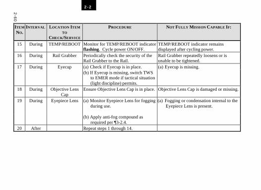
2-6
0
2-2
ITEM NO.
INTERVAL LOCATION ITEM TO
CHECK/SERVICE
PROCEDURE NOT FULLY MISSION CAPABLE IF:
15 During TEMP/REBOOT Monitor for TEMP/REBOOT indicator flashing. Cycle power ON/OFF.
TEMP/REBOOT indicator remains displayed after cycling power.
16 During Rail Grabber Periodically check the security of the Rail Grabber to the Rail.
Rail Grabber repeatedly loosens or is unable to be tightened.
(a) Check if Eyecup is in place. (a) Eyecup is missing. 17 During Eyecup (b) If Eyecup is missing, switch TWS
to EMER mode if tactical situation (light discipline) permits.
(b)
18 During Objective Lens Cap
Ensure Objective Lens Cap is in place. Objective Lens Cap is damaged or missing.
(a) Monitor Eyepiece Lens for fogging during use.
(a) Fogging or condensation internal to the Eyepiece Lens is present.
19 During Eyepiece Lens
(b) Apply anti-fog compound as required per ¶3-2.4.
(a)
20 After Repeat steps 1 through 14.
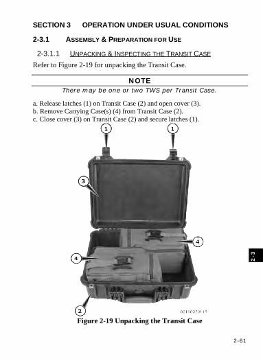
2-61
2-3
SECTION 3 OPERATION UNDER USUAL CONDITIONS
2-3.1 ASSEMBLY & PREPARATION FOR USE
2-3.1.1 UNPACKING & INSPECTING THE TRANSIT CASE Refer to Figure 2-19 for unpacking the Transit Case.
NOTE There may be one or two TWS per Transit Case.
a. Release latches (1) on Transit Case (2) and open cover (3). b. Remove Carrying Case(s) (4) from Transit Case (2). c. Close cover (3) on Transit Case (2) and secure latches (1).
Figure 2-19 Unpacking the Transit Case
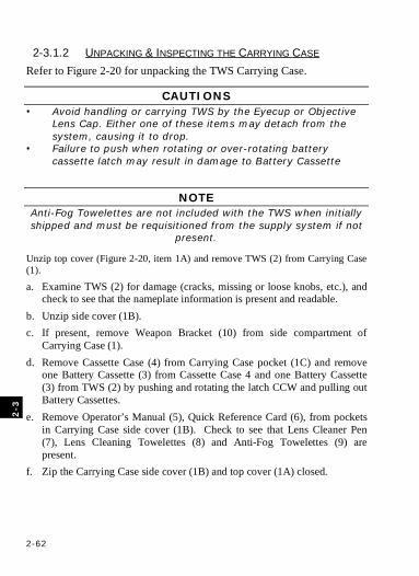
2-62
2
-3
2-3.1.2 UNPACKING & INSPECTING THE CARRYING CASE Refer to Figure 2-20 for unpacking the TWS Carrying Case.
CAUTIONS • Avoid handling or carrying TWS by the Eyecup or Objective
Lens Cap. Either one of these items may detach from the system, causing it to drop.
• Failure to push when rotating or over-rotating battery cassette latch may result in damage to Battery Cassette
NOTE Anti-Fog Towelettes are not included with the TWS when initially shipped and must be requisitioned from the supply system if not
present.
Unzip top cover (Figure 2-20, item 1A) and remove TWS (2) from Carrying Case (1).
a. Examine TWS (2) for damage (cracks, missing or loose knobs, etc.), and check to see that the nameplate information is present and readable.
b. Unzip side cover (1B). c. If present, remove Weapon Bracket (10) from side compartment of
Carrying Case (1). d. Remove Cassette Case (4) from Carrying Case pocket (1C) and remove
one Battery Cassette (3) from Cassette Case 4 and one Battery Cassette (3) from TWS (2) by pushing and rotating the latch CCW and pulling out Battery Cassettes.
e. Remove Operator’s Manual (5), Quick Reference Card (6), from pockets in Carrying Case side cover (1B). Check to see that Lens Cleaner Pen (7), Lens Cleaning Towelettes (8) and Anti-Fog Towelettes (9) are present.
f. Zip the Carrying Case side cover (1B) and top cover (1A) closed.

2-63
2-3
Figure 2-20 Unpacking the Carrying Case
(1)
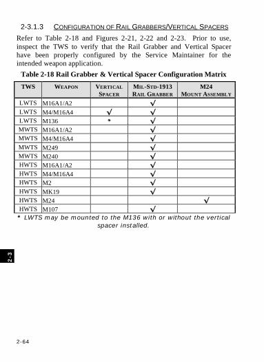
2-64
2
-3
2-3.1.3 CONFIGURATION OF RAIL GRABBERS/VERTICAL SPACERS Refer to Table 2-18 and Figures 2-21, 2-22 and 2-23. Prior to use, inspect the TWS to verify that the Rail Grabber and Vertical Spacer have been properly configured by the Service Maintainer for the intended weapon application.
Table 2-18 Rail Grabber & Vertical Spacer Configuration Matrix
TWS WEAPON VERTICAL SPACER
MIL-STD-1913 RAIL GRABBER
M24 MOUNT ASSEMBLY
LWTS M16A1/A2 √ LWTS M4/M16A4 √ √ LWTS M136 * √ MWTS M16A1/A2 √ MWTS M4/M16A4 √ MWTS M249 √ MWTS M240 √ HWTS M16A1/A2 √ HWTS M4/M16A4 √ HWTS M2 √ HWTS MK19 √ HWTS M24 √ HWTS M107 √ * LWTS may be mounted to the M136 with or without the vertical
spacer installed.
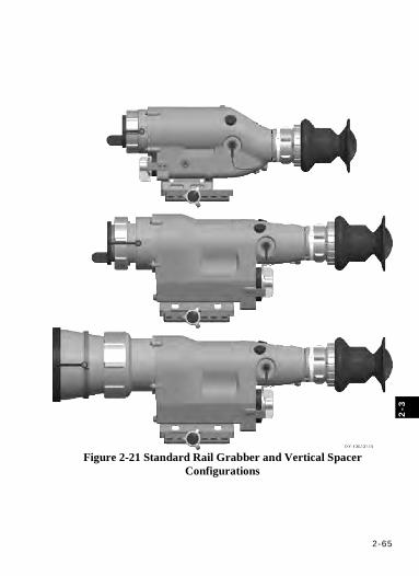
2-65
2-3
Figure 2-21 Standard Rail Grabber and Vertical Spacer
Configurations
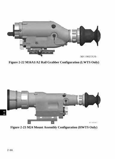
2-66
2
-3
Figure 2-22 M16A1/A2 Rail Grabber Configuration (LWTS Only)
Figure 2-23 M24 Mount Assembly Configuration (HWTS Only)
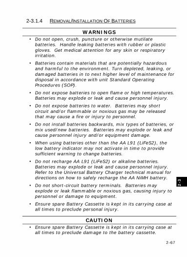
2-67
2-3
2-3.1.4 REMOVAL/INSTALLATION OF BATTERIES
WARNINGS • Do not open, crush, puncture or otherwise mutilate
batteries. Handle leaking batteries with rubber or plastic gloves. Get medical attention for any skin or respiratory irritation.
• Batteries contain materials that are potentially hazardous and harmful to the environment. Turn depleted, leaking, or damaged batteries in to next higher level of maintenance for disposal in accordance with unit Standard Operating Procedures (SOP).
• Do not expose batteries to open flame or high temperatures. Batteries may explode or leak and cause personnel injury.
• Do not expose batteries to water. Batteries may short circuit and/or flammable or noxious gas may be released that may cause a fire or injury to personnel.
• Do not install batteries backwards, mix types of batteries, or mix used/new batteries. Batteries may explode or leak and cause personnel injury and/or equipment damage.
• When using batteries other than the AA L91 (LiFeS2), the low battery indicator may not activate in time to provide sufficient warning to change batteries.
• Do not recharge AA L91 (LiFeS2) or alkaline batteries. Batteries may explode or leak and cause personnel injury. Refer to the Universal Battery Charger technical manual for directions on how to safely recharge the AA NiMH battery.
• Do not short-circuit battery terminals. Batteries may explode or leak flammable or noxious gas, causing injury to personnel or damage to equipment.
• Ensure spare Battery Cassette is kept in its carrying case at all times to preclude personal injury.
CAUTION • Ensure spare Battery Cassette is kept in its carrying case at
all times to preclude damage to the battery cassette.
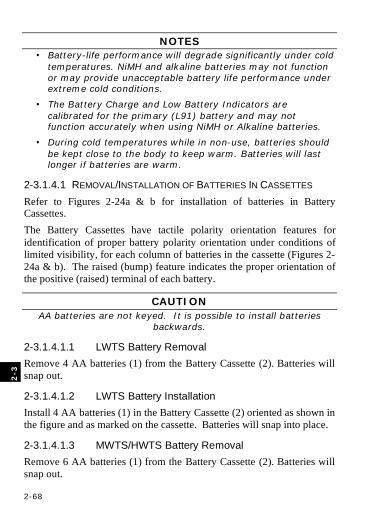
2-68
2
-3
NOTES • Battery-life performance will degrade significantly under cold
temperatures. NiMH and alkaline batteries may not function or may provide unacceptable battery life performance under extreme cold conditions.
• The Battery Charge and Low Battery Indicators are calibrated for the primary (L91) battery and may not function accurately when using NiMH or Alkaline batteries.
• During cold temperatures while in non-use, batteries should be kept close to the body to keep warm. Batteries will last longer if batteries are warm.
2-3.1.4.1 REMOVAL/INSTALLATION OF BATTERIES IN CASSETTES Refer to Figures 2-24a & b for installation of batteries in Battery Cassettes. The Battery Cassettes have tactile polarity orientation features for identification of proper battery polarity orientation under conditions of limited visibility, for each column of batteries in the cassette (Figures 2-24a & b). The raised (bump) feature indicates the proper orientation of the positive (raised) terminal of each battery.
CAUTION AA batteries are not keyed. It is possible to install batteries
backwards.
2-3.1.4.1.1 LWTS Battery Removal Remove 4 AA batteries (1) from the Battery Cassette (2). Batteries will snap out.
2-3.1.4.1.2 LWTS Battery Installation Install 4 AA batteries (1) in the Battery Cassette (2) oriented as shown in the figure and as marked on the cassette. Batteries will snap into place.
2-3.1.4.1.3 MWTS/HWTS Battery Removal Remove 6 AA batteries (1) from the Battery Cassette (2). Batteries will snap out.
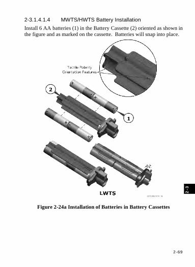
2-69
2-3
2-3.1.4.1.4 MWTS/HWTS Battery Installation Install 6 AA batteries (1) in the Battery Cassette (2) oriented as shown in the figure and as marked on the cassette. Batteries will snap into place.
Figure 2-24a Installation of Batteries in Battery Cassettes
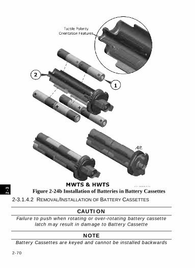
2-70
2
-3
Figure 2-24b Installation of Batteries in Battery Cassettes 2-3.1.4.2 REMOVAL/INSTALLATION OF BATTERY CASSETTES
CAUTION Failure to push when rotating or over-rotating battery cassette
latch may result in damage to Battery Cassette
NOTE Battery Cassettes are keyed and cannot be installed backwards
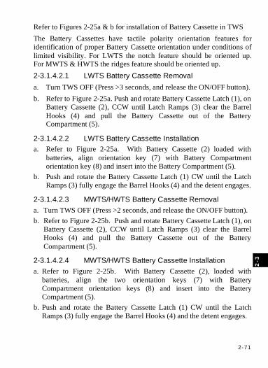
2-71
2-3
Refer to Figures 2-25a & b for installation of Battery Cassette in TWS The Battery Cassettes have tactile polarity orientation features for identification of proper Battery Cassette orientation under conditions of limited visibility. For LWTS the notch feature should be oriented up. For MWTS & HWTS the ridges feature should be oriented up. 2-3.1.4.2.1 LWTS Battery Cassette Removal a. Turn TWS OFF (Press >3 seconds, and release the ON/OFF button). b. Refer to Figure 2-25a. Push and rotate Battery Cassette Latch (1), on
Battery Cassette (2), CCW until Latch Ramps (3) clear the Barrel Hooks (4) and pull the Battery Cassette out of the Battery Compartment (5).
2-3.1.4.2.2 LWTS Battery Cassette Installation a. Refer to Figure 2-25a. With Battery Cassette (2) loaded with
batteries, align orientation key (7) with Battery Compartment orientation key (8) and insert into the Battery Compartment (5).
b. Push and rotate the Battery Cassette Latch (1) CW until the Latch Ramps (3) fully engage the Barrel Hooks (4) and the detent engages.
2-3.1.4.2.3 MWTS/HWTS Battery Cassette Removal a. Turn TWS OFF (Press >2 seconds, and release the ON/OFF button). b. Refer to Figure 2-25b. Push and rotate Battery Cassette Latch (1), on
Battery Cassette (2), CCW until Latch Ramps (3) clear the Barrel Hooks (4) and pull the Battery Cassette out of the Battery Compartment (5).
2-3.1.4.2.4 MWTS/HWTS Battery Cassette Installation a. Refer to Figure 2-25b. With Battery Cassette (2), loaded with
batteries, align the two orientation keys (7) with Battery Compartment orientation keys (8) and insert into the Battery Compartment (5).
b. Push and rotate the Battery Cassette Latch (1) CW until the Latch Ramps (3) fully engage the Barrel Hooks (4) and the detent engages.

2-72
2
-3
Figure 2-25a Battery Cassette Installation

2-73
2-3
Figure 2-25b Battery Cassette Installation
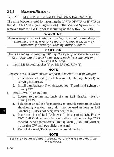
2-74
2
-3
2-3.2 MOUNTING/REMOVAL 2-3.2.1 MOUNTING/REMOVAL OF TWS ON M16A1/A2 RIFLE
The same bracket is used for mounting the LWTS, MWTS, or HWTS on the M16A1/A2 rifle (see Figure 2-26). The Vertical Spacer must be removed from the LWTS prior to mounting on the M16A1/A2 Rifle.
WARNING Ensure weapon is not loaded and safety is on before installing or
removing bracket/TWS to weapon. A loaded weapon may accidentally discharge, causing injury or death.
CAUTION Avoid handling or carrying TWS by the Eyecup or Objective Lens
Cap. Any one of these items may detach from the system, causing it to drop.
a. Install M16A1/A2 bracket (1) on M16A1/A2 Rifle (2).
NOTE Ensure Bracket thumbwheel lanyard is toward front of weapon.
1. Place threaded rod (3) of bracket (1) through hole (4) of carrying handle (5).
2. Install thumbwheel (6) on threaded rod (3) and hand tighten by turning CW.
b. Install TWS (7) on Rail (8). 1. Loosen torque-limiting knob (9) on Rail Grabber (10) by
turning CCW. 2. Select slot on rail (8) for mounting to provide optimum fit when
shouldering weapon. Any slot may be used as long as Rail Grabber (10) does not hang over edge of rail.
3. Place bar (11) of Rail Grabber (10) in slot of rail (8). Ensure TWS Rail Grabber rests fully on rail and while pushing TWS forward, hand tighten torque-limiting knob (9) on Rail Grabber, by turning CW until two clicks are heard.
4. Record slot used, TWS and weapon serial numbers.
NOTE Zero may be invalidated if M16A1/A2 bracket is removed from
the weapon.
2-75
2-3
c. Remove TWS (7) from M16A1/A2 Rifle (2). 1. Loosen torque-limiting knob (9) on Rail Grabber (10) by
turning CCW. 2. Close Lens Cap and remove TWS (7) from rail (8). 3. Unscrew thumbwheel (6) CCW from M16A1/A2 bracket (1). 4. Remove M16A1/A2 bracket (1) from carrying handle (5). 5. Screw thumbwheel (6) on to M16A1/A2 bracket (1). 6. Tighten torque-limiting knob by turning CW until 2 clicks are
heard.
Figure 2-26 TWS Mounting on M16A1/A2 Rifle
2-76
2
-3
2-3.2.2 MOUNTING/REMOVAL OF TWS ON M4 SERIES CARBINE OR M16A4 RIFLE
Refer to Figure 2-27 for mounting or removing LWTS, MWTS, or HWTS on M4 series Carbine or M16A4 Rifle.
WARNING Ensure weapon is not loaded and safety is on before installing or removing TWS to weapon. A loaded weapon may accidentally
discharge, causing injury or death.
CAUTION Avoid handling or carrying TWS by the Eyecup, Objective Lens
Cap. Any one of these items may detach from the system, causing it to drop.
a. If carrying handle is present, turn two knobs CCW on carrying handle to loosen and remove carrying handle from rail of weapon. Retain carrying handle.
NOTE Ensure Vertical spacer has been installed by maintenance on
LWTS being mounted to M4 Carbine or M16A4 Rifle.
b. Install LWTS with Vertical Spacer (1) or M/HWTS on Rail (3). 1. Loosen torque-limiting knob (2) on Rail Grabber (4) by turning
CCW. 2. Select slot on Rail (3) for mounting to provide optimum fit
when shouldering weapon so that Rail Grabber (4) does not overhang edge of rail. When Backup Iron Sight (BIS) is present, ensure a minimum gap of 1 slot (LWTS) and 3 slots (M/HWTS) between back of Rail Grabber and front of BIS.
3. Place bar (5) of Rail Grabber (4) in slot of rail (3). Ensure TWS Rail Grabber rests fully on rail and while pushing TWS forward, hand tighten torque-limiting knob (2) on Rail Grabber, by turning CW until two clicks are heard.
4. Record slot used, TWS and weapon serial numbers.
2-77
2-3
c. Remove TWS (1) from Rail (3). 1. Loosen torque-limiting knob (2) by turning CCW. 2. Close Lens Cap and remove TWS (1) from rail (3). 3. If removed in step a., place carrying handle on rail of M4 Series
Carbine or M16A4 Rifle. 4. Hand-tighten two knobs on carrying handle by turning CW. 5. Tighten torque-limiting knob by turning CW until 2 clicks are
heard.
Figure 2-27 TWS Mounting on M4 Series Carbine/M16A4 Rifle
2-78
2
-3
2-3.2.3 MOUNTING/REMOVAL OF LWTS ON M136 (AT4) Refer to Figure 2-28 for mounting or removing LWTS on M136 (AT4).
WARNING Ensure weapon safeties are on before installing or removing Bracket/TWS to weapon. A loaded weapon may accidentally
discharge, causing injury or death.
CAUTIONS • Avoid handling or carrying TWS by the Eyecup, Objective
Lens Cap. Any one of these items may detach from the system, causing it to drop.
• Do not stand the M136 on end. The seal may be punctured affecting weapon performance.
a. Install AT4 Bracket (1) on AT4 (2). 1. Position AT4 bracket (1) on left side of AT4 (2), so the marking
“FRONT” is over the rear sight housing (3). 2. Spread pivot bracket (4) open and place top of support bracket
on rear sight housing (3) and bottom of support bracket against strap boss (5).
3. Swing pivot bracket (4) around AT4 (2) and secure by turning the locking latch (6) CW to engage latch shoulder screw (7).
NOTE LWTS may be mounted to the AT4 with or without the vertical
spacer installed.
b. Install LWTS (8) on Rail (9). 1. Loosen torque-limiting knob (10) on Rail Grabber (11) by
turning CCW. 2. Select slot on Rail (9) for mounting to provide optimum fit
when shouldering weapon. Any slot may be used as long as Rail Grabber (11) does not hang over edge of rail.
3. Place bar (12) of Rail Grabber (11) in slot of rail (9). Ensure TWS Rail Grabber rests fully on rail and while pushing TWS forward, hand tighten torque-limiting knob (10) on Rail Grabber, by turning CW until two clicks are heard.
4. Record slot used.
2-79
2-3
c. Remove LWTS (8) from AT4 (2). 1. Loosen torque-limiting knob (10) on Rail Grabber (11) by
turning CCW. 2. Close Lens Cap and remove LWTS (8) from rail (9). 3. Turn locking latch (6) CCW until released from latch shoulder
screw (7), swing pivot bracket (4) open and remove Bracket (1) from Weapon (2).
4. Retain Bracket. 5. Tighten torque-limiting knob by turning CW until 2 clicks are
heard.
Figure 2-28 LWTS Mounting on AT4
2-80
2
-3
2-3.2.4 MOUNTING/REMOVAL OF MWTS ON M249 SQUAD AUTOMATIC WEAPON (SAW)
Refer to Figure 2-29 for mounting/removing MWTS on M249 SAW.
WARNING Ensure weapon is not loaded and safety is on before installing
and removing TWS to and from weapon. A loaded weapon may accidentally discharge, causing injury or death.
CAUTIONS • Avoid handling or carrying TWS by the Eyecup, Objective Lens
Cap. Any one of these items may detach from the system, causing it to drop.
• The TWS must be mounted on slot T5 or T6 of the rail, otherwise damage to the TWS may result.
a. Install MWTS (1) on Rail (2). 1. Loosen torque-limiting knob (3) on Rail Grabber (4) by turning
CCW. 2. Select slot T5 or T6 on Rail (2) for mounting. 3. Place bar (5) of Rail Grabber (4) in slot of rail (2). Ensure TWS
Rail Grabber rests fully on rail and while pushing TWS forward, hand tighten torque-limiting knob (3) on Rail Grabber, by turning CW until two clicks are heard.
4. Record slot used, TWS and weapon serial numbers. b. Remove MWTS (1) from Rail (2).
1. Loosen torque-limiting knob (3) on Rail Grabber (4) by turning CCW.
2. Close Lens Cap and remove MWTS (1) from rail (2). 3. Tighten torque-limiting knob by turning CW until 2 clicks are
heard.
2-81
2-3
Figure 2-29 MWTS Mounting on M249 Squad Automatic Weapon
(SAW)
2-82
2
-3
2-3.2.5 MOUNTING/REMOVAL OF MWTS ON M240 MACHINE GUN
Refer to Figure 2-30 for mounting and removing MWTS on M240 machine gun.
WARNING Ensure weapon is not loaded and safety is on before installing and removing TWS to and from weapon. A loaded weapon may
accidentally discharge, causing injury or death.
CAUTIONS • Avoid handling or carrying TWS by the Eyecup, Objective
Lens Cap. Any one of these items may detach from the system, causing it to drop.
• The TWS must be mounted in a slot (T4 through T12 only) provided the Rail Grabber does not overhang the rail.
a. Ensure iron sight is completely down. b. Install MWTS (1) on M240 Machine Gun (2).
1. Loosen torque-limiting knob (3) on Rail Grabber (4) by turning CCW.
2. Select a slot (T4 through T12 only) on Rail (5) for mounting. 3. Place bar (6) of Rail Grabber (4) in slot of rail (5). Ensure TWS
Rail Grabber rests fully on rail and while pushing TWS forward, hand tighten torque-limiting knob (3) on Rail Grabber, by turning CW until two clicks are heard.
4. Record slot used, TWS and weapon serial numbers. c. Remove MWTS (1) from M240 Machine Gun (2).
1. Loosen torque-limiting knob (3) on Rail Grabber (4) by turning CCW.
2. Close Lens Cap and remove MWTS (1) from rail (5). 3. Tighten torque-limiting knob by turning CW until 2 clicks are
heard.
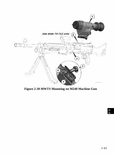
2-83
2-3
Figure 2-30 MWTS Mounting on M240 Machine Gun
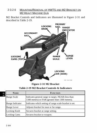
2-84
2
-3
2-3.2.6 MOUNTING/REMOVAL OF HWTS AND M2 BRACKET ON M2 HEAVY MACHINE GUN
M2 Bracket Controls and Indicators are illustrated in Figure 2-31 and described in Table 2-19.
Figure 2-31 M2 Bracket
Table 2-19 M2 Bracket Controls & Indicators
NAME FUNCTION
Range Scale Indicates general range to target, NEAR (less than 1300 meters) or FAR (greater than 1300 meters).
Range Indicator Indicates which setting of range scale bracket is set. Range Lever Adjusts bracket for near or far range. Locking Knob Secures bracket at range setting. Locking Cams Secures bracket to weapon.
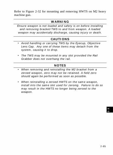
2-85
2-3
Refer to Figure 2-32 for mounting and removing HWTS on M2 heavy machine gun.
WARNING Ensure weapon is not loaded and safety is on before installing
and removing bracket/TWS to and from weapon. A loaded weapon may accidentally discharge, causing injury or death.
CAUTIONS • Avoid handling or carrying TWS by the Eyecup, Objective
Lens Cap. Any one of these items may detach from the system, causing it to drop.
• The TWS may be mounted in any slot provided the Rail Grabber does not overhang the rail.
NOTES • When removing and reinstalling the M2 bracket from a
zeroed weapon, zero may not be retained. A field zero should again be performed as soon as possible.
• When reinstalling a zeroed HWTS on the same weapon, install into the same slot used for zeroing. Failure to do so may result in the HWTS no longer being zeroed to the weapon.
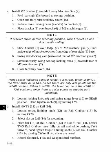
2-86
2
-3
a. Install M2 Bracket (1) on M2 Heavy Machine Gun (2). 1. Fold rear sight (3) forward to storage position. 2. Open and fully raise feed tray cover (16). 3. Release three locking cams (4 and 5) on bracket (1). 4. Place bracket (1) over breech (6) of M2 machine gun (2).
NOTE If bracket sticks before reaching position, rock bracket up and
down while sliding.
5. Slide bracket (1) over ledge (7) of M2 machine gun (2) until inside edge of bracket touches front edge of rear sight (8) base.
6. Swing side-locking cam (4) toward rear of M2 machine gun (2). 7. Simultaneously swing two top locking cams (5) towards rear of
M2 machine gun (2). 8. Close feed tray cover (16).
NOTE Range scale indicates general range to a target. When in WFOV
the lever must be in NEAR since there are only aim points for the NEAR position. When in NFOV, the lever can be in the NEAR or
FAR positions since there are aim points to support both positions.
9. Loosen locking knob (9) and swing range lever (10) to NEAR position. Hand tighten knob (9), by turning CW.
b. Install HWTS (11) on Rail (14). 1. Loosen torque-limiting knob (12) on Rail Grabber (13) by
turning CCW. 2. Select slot on Rail (14) for mounting. 3. Place bar (15) of Rail Grabber (13) in slot of rail (14). Ensure
TWS Rail Grabber rests fully on rail and while pushing TWS forward, hand tighten torque-limiting knob (12) on Rail Grabber (13), by turning CW until two clicks are heard.
4. Record slot used, TWS and weapon serial numbers.

2-87
2-3
c. Remove HWTS (11) from Rail 14). 1. Loosen torque-limiting knob (12) on Rail Grabber (13) by
turning CCW. 2. Close Lens Cap and remove HWTS (11) from rail (14). 3. Tighten torque-limiting knob by turning CW until 2 clicks are
heard. d. Remove M2 Bracket (1) from M2 Heavy Machine Gun (2).
1. Open and fully raise feed tray cover (16). 2. Release two top locking cams (5). 3. Release side locking cam (4). 4. Slide bracket (1) off of M2 machine gun (2). 5. Close feed tray cover.
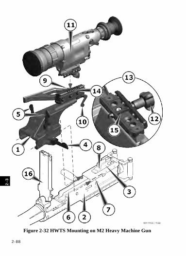
2-88
2
-3
Figure 2-32 HWTS Mounting on M2 Heavy Machine Gun

2-89
2-3
2-3.2.7 MOUNTING/REMOVAL OF HWTS AND MK19 BRACKET ON MK19 GRENADE MACHINE GUN
MK19 Bracket Controls and Indicators are illustrated in Figure 2-33 and described in Table 2-20.
Figure 2-33 MK19 Bracket
Table 2-20 MK19 Bracket Controls & Indicators
NAME FUNCTION
Range Scales Indicates estimated distance to target in meters.
Range Indicators Indicates which value of range scale MK19 bracket is set.
Locking Knob Secures MK19 bracket at range setting.
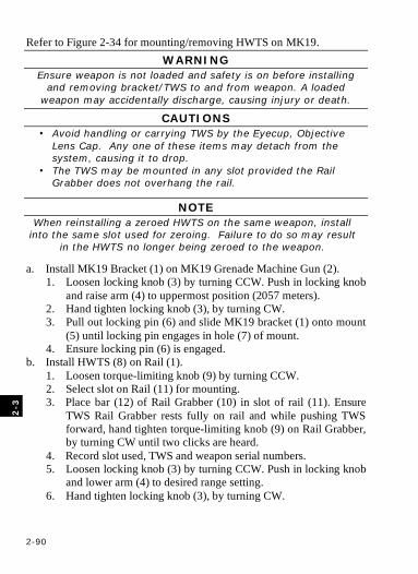
2-90
2
-3
Refer to Figure 2-34 for mounting/removing HWTS on MK19. WARNING
Ensure weapon is not loaded and safety is on before installing and removing bracket/TWS to and from weapon. A loaded
weapon may accidentally discharge, causing injury or death.
CAUTIONS • Avoid handling or carrying TWS by the Eyecup, Objective
Lens Cap. Any one of these items may detach from the system, causing it to drop.
• The TWS may be mounted in any slot provided the Rail Grabber does not overhang the rail.
NOTE When reinstalling a zeroed HWTS on the same weapon, install
into the same slot used for zeroing. Failure to do so may result in the HWTS no longer being zeroed to the weapon.
a. Install MK19 Bracket (1) on MK19 Grenade Machine Gun (2). 1. Loosen locking knob (3) by turning CCW. Push in locking knob
and raise arm (4) to uppermost position (2057 meters). 2. Hand tighten locking knob (3), by turning CW. 3. Pull out locking pin (6) and slide MK19 bracket (1) onto mount
(5) until locking pin engages in hole (7) of mount. 4. Ensure locking pin (6) is engaged.
b. Install HWTS (8) on Rail (1). 1. Loosen torque-limiting knob (9) by turning CCW. 2. Select slot on Rail (11) for mounting. 3. Place bar (12) of Rail Grabber (10) in slot of rail (11). Ensure
TWS Rail Grabber rests fully on rail and while pushing TWS forward, hand tighten torque-limiting knob (9) on Rail Grabber, by turning CW until two clicks are heard.
4. Record slot used, TWS and weapon serial numbers. 5. Loosen locking knob (3) by turning CCW. Push in locking knob
and lower arm (4) to desired range setting. 6. Hand tighten locking knob (3), by turning CW.
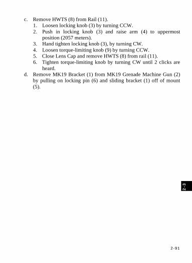
2-91
2-3
c. Remove HWTS (8) from Rail (11). 1. Loosen locking knob (3) by turning CCW. 2. Push in locking knob (3) and raise arm (4) to uppermost
position (2057 meters). 3. Hand tighten locking knob (3), by turning CW. 4. Loosen torque-limiting knob (9) by turning CCW. 5. Close Lens Cap and remove HWTS (8) from rail (11). 6. Tighten torque-limiting knob by turning CW until 2 clicks are
heard. d. Remove MK19 Bracket (1) from MK19 Grenade Machine Gun (2)
by pulling on locking pin (6) and sliding bracket (1) off of mount (5).
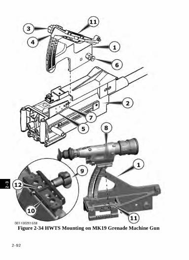
2-92
2
-3
Figure 2-34 HWTS Mounting on MK19 Grenade Machine Gun
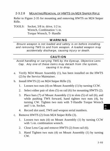
2-93
2-3
2-3.2.8 MOUNTING/REMOVAL OF HWTS ON M24 SNIPER RIFLE Refer to Figure 2-35 for mounting and removing HWTS on M24 Sniper Rifle. TOOLS: Socket, 3/8 in. drive, 1/2 in. Wrench, Combination ½ in.
Torque Wrench, T- Handle
WARNING Ensure weapon is not loaded and safety is on before installing and removing TWS to and from weapon. A loaded weapon may
accidentally discharge, causing injury or death.
CAUTION Avoid handling or carrying TWS by the Eyecup, Objective Lens
Cap. Any one of these items may detach from the system, causing it to drop.
a. Verify M24 Mount Assembly (1), has been installed on the HWTS (2) by the Service Maintainer.
b. Install HWTS (2) on M24 Sniper Rifle (3). 1. Loosen two nuts (4) on Mount Assembly (1) by turning CCW. 2. Select either pair of slots (5) on rail (6) for mounting HWTS (2). 3. Place bars (7) of Mount Assembly (1) in slots (5) of rail (6), and
while pushing TWS forward, hand tighten two nuts (4), by turning CW. Tighten two nuts with T-Handle Torque Wrench and ½-in. Socket.
4. Record slot used, TWS and weapon serial numbers. c. Remove HWTS (2) from M24 Sniper Rifle (3).
1. Loosen two nuts (4) on Mount Assembly (1) by turning CCW with ½-in. combination wrench.
2. Close Lens Cap and remove HWTS (2) from rail (6). 3. Hand Tighten two nuts (4) on Mount Assembly (1) by turning
CW.
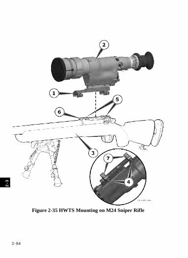
2-94
2
-3
Figure 2-35 HWTS Mounting on M24 Sniper Rifle
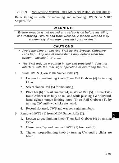
2-95
2-3
2-3.2.9 MOUNTING/REMOVAL OF HWTS ON M107 SNIPER RIFLE Refer to Figure 2-36 for mounting and removing HWTS on M107 Sniper Rifle.
WARNING Ensure weapon is not loaded and safety is on before installing and removing TWS to and from weapon. A loaded weapon may
accidentally discharge, causing injury or death.
CAUTIONS • Avoid handling or carrying TWS by the Eyecup, Objective
Lens Cap. Any one of these items may detach from the system, causing it to drop.
• The TWS may be mounted in any slot provided it does not interfere with the rear sight operation or overhang the rail.
a. Install HWTS (1) on M107 Sniper Rifle (2). 1. Loosen torque-limiting knob (3) on Rail Grabber (4) by turning
CCW. 2. Select slot on Rail (5) for mounting. 3. Place bar (6) of Rail Grabber (4) in slot of Rail (5). Ensure TWS
Rail Grabber rests fully on rail and while pushing TWS forward, hand tighten torque-limiting knob (3) on Rail Grabber (4), by turning CW until two clicks are heard.
4. Record slot used, TWS and weapon serial numbers. b. Remove HWTS (1) from M107 Sniper Rifle (2).
1. Loosen torque-limiting knob (3) on Rail Grabber (4) by turning CCW.
2. Close Lens Cap and remove HWTS (1) from rail (5). 3. Tighten torque-limiting knob by turning CW until 2 clicks are
heard.
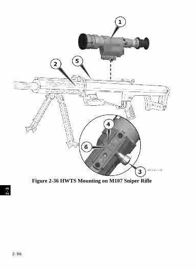
2-96
2
-3
Figure 2-36 HWTS Mounting on M107 Sniper Rifle
2-97
2-3
2-3.3 OPERATION
CAUTION Do not attempt to view the Sun with the TWS. The TWS may be
permanently damaged.
2-3.3.1 TURN-ON AND INITIAL ADJUSTMENTS
NOTES
• The TWS begins a warm-up period when step (a) is performed. The period will not exceed 2 minutes.
• During the warm-up period, the startup screen is displayed (see Figure 2-2a).
• The Operator should occasionally check the display for the Battery Indicator and Low Battery Indicator. Dying batteries could cause the TWS to shut down without the user knowing.
• The TWS always powers up in the Auto 1 condition (automatic gain/level using ROI 1).
• The TWS always powers up with the display brightness set to a default value.
• The TWS always powers up in the WFOV.
• The TWS always powers up with the last weapon (reticle) selected and the last coordinate set for each reticle.
• The TWS may require periodic, manual calibration to restore optimal image quality. The calibration is initiated with a <3 second press and release of the ON/OFF button (there is a 20-second timeout between calibration events) or when the system transitions from the STANDBY mode to ON.
• The TWS may need to be re-calibrated more frequently in the first 30 minutes after startup and during significant ambient temperature changes.
a. Press >3 seconds then release the ON/OFF button (turns on TWS). b. Press eye to the Eyecup (activates the Operate Sub-Mode).
2-98
2
-3
c. Adjust the Brightness control to optimize display for ambient light conditions. 1. Press <2 seconds and release the MODE button to advance TWS
state to DISPLAY. 2. Deflect the FUNCTION switch up/down to select the optimum
display brightness level. 3. Press <2 seconds and release the MODE button to advance TWS
state to CONTRAST. d. Adjust Diopter Ring on Eyepiece for best focus of display
symbology. e. Open Objective Lens Cap. f. Adjust Objective Focus Ring on Objective Lens for best image focus. g. If necessary, momentarily press, then release the FUNCTION switch
center pushbutton to advance/select auto gain/level ROI (AUTO [1], AUTO [2], AUTO [3]) for best image.
NOTE If level and gain are manually adjusted and Standby mode is then
entered for >20 seconds, the TWS will return to the last AUTO setting used when the eyecup is depressed.
h. Auto settings do not always provide optimum image, if necessary, select/adjust manual gain/level condition for optimum image. 1. Deflect the FUNCTION switch left/right to select the optimum
manual level setting. 2. Deflect the FUNCTION switch up/down to select the optimum
manual gain (contrast) setting. 3. Repeat manual level and manual gain settings as required.
i. If necessary, momentarily press, then release the FUNCTION switch center pushbutton to reset auto gain/level from a manual condition.
j. Press the ON/OFF button <3 seconds to calibrate the image. Press the ON/OFF button <3 seconds again, within 20 seconds of initial press, to toggle the image polarity (WHT HOT/BLK HOT) for the polarity condition that provides the best image.
k. As required, momentarily press the FOV button to toggle between WFOV/NFOV (changes FOV).
2-99
2-3
l. Power-on default is a black reticle on WHT HOT image and white
reticle on a BLK HOT image. If required to improve contrast between reticle aimpoint and target, a fixed reticle color may be selected. 1. Press <2 seconds and release the MODE button to advance TWS
state to DISPLAY. 2. Deflect the FUNCTION switch left/right to select a fixed
black/white reticle respectively. 3. Press <2 seconds and release the MODE button to advance TWS
state to CONTRAST. m. Repeat steps f through l as needed to accomplish mission. n. Following operation, press >3 seconds then release the ON/OFF
button (turns off power). o. Close Objective Lens Cap.
2-3.3.2 BORESIGHT, ZERO & SIGHT ALIGNMENT
NOTE Refer to Operator’s Manual for AN/PEM-1 Laser Borelight System
(LBS-300) for laser Boresighting procedures.
The TWS must be zeroed or sight aligned with the host weapon before being mission capable. The TWS may be boresighted prior to zeroing. For zeroing at 25 meters, a thermal zeroing target must be prepared per ¶2-3.3.2.1.
2-3.3.2.1 THERMAL ZEROING TARGET PREPARATION Supplies:
• Box, Shipping (Appendix D Item 4) • Tape, Pressure Sensitive Adhesive (Appendix D
Item 5) • Target, M16, 25m Zeroing (Appendix D Item 6)
2-100
2
-3
a. Modify a M16A2 25m zeroing target, using only the M16A2 side of the target. 1. Cut a square hole, 4 squares wide by 4 squares high, (as shown
in Figure 2-37) in a M16A2 25m zeroing target. 2. Cut out a rectangle from corrugated cardboard box, the same
size as the M16A2 25m zeroing target (22 X 28 cm. or 8.5 X 11 in.).
3. Estimate 2.5 cm. (1 in.) in from each side of corrugated cardboard rectangle, and cut out a rectangular hole as shown in Figure 2-38.
4. Tape corrugated cardboard frame to back of modified M16A2 25m zeroing target. Ensure that tape does not obstruct the airflow through the corrugation of the cardboard.
b. Affix thermal blanket to a standard E-type silhouette, and then affix target to the thermal blanket. Only tape corners (see Figure 2-39).
c. A 4x4 square block should be centered and marked around the desired point of impact (see figure 2-40) per table 2-21, except for the M249 which shall use a 6x6 square block.
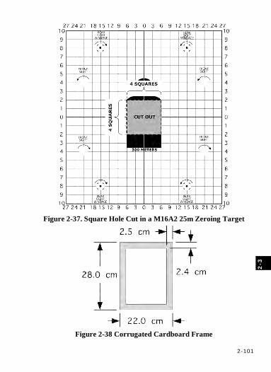
2-101
2-3
Figure 2-37. Square Hole Cut in a M16A2 25m Zeroing Target
Figure 2-38 Corrugated Cardboard Frame
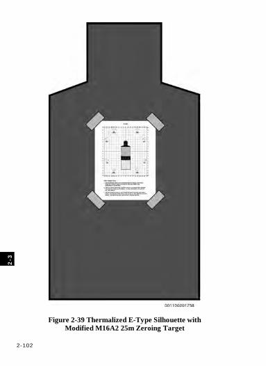
2-102
2
-3
Figure 2-39 Thermalized E-Type Silhouette with Modified M16A2 25m Zeroing Target
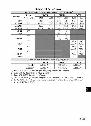
2-103
2-3
Table 2-21 Zero Offsets 10M LBS/25M BATTLEFIELD ZERO OFFSETS (CM (MOA))1
LWTS MWTS HWTS WEAPON ZERO RANGE(M) 10M 25M 10M 25M 10M 25M
M4/ M16A4 300
8.5 (29.2)
5.1 (7.0)
9.3 (31.2)
5.9 (8.1)
9.3 (31.2)
5.9 (8.1)
M16A1/ M16A2 300
12.6 (43.3)
9.4 (12.9)
14.4 (49.5)
11.2 (15.4)
14.4 (49.5)
11.2 (15.4)
M249 (Long)
400
11.9 (40.9)
6 (8.3)
M240 500
9.2
(31.6) 2.2
(3.0)
M22 500
19.0
(65.3) 14.7
(20.2)
M24 100
11.4
(39.2) 10.7
(14.7)
M107 100
N/A 11.1
(15.3) MK193 500 4
SHOT GROUP MOVEMENT PER CLICK5 (CM)(MOA) LWTS MWTS HWTS
10m LBS 0.24 (0.83) 0.19 (0.64) 0.09 (0.32) 25m Zero 0.60 (0.83) 0.47 (0.64) 0.23 (0.32)
1) Positive value indicates LBS Spot/shot group zone below aim point. 2) Zero with M2 Bracket set to NEAR position. 3) Zero with MK19 Bracket set to 500m. 4) 10m Laser Boresight desired aim point is 17.4cm right and 19.8cm below LBS spot. 5) In the WFOV the reticle position increments in steps of two (2) for the LWTS and 3
for the MWTS and HWTS.
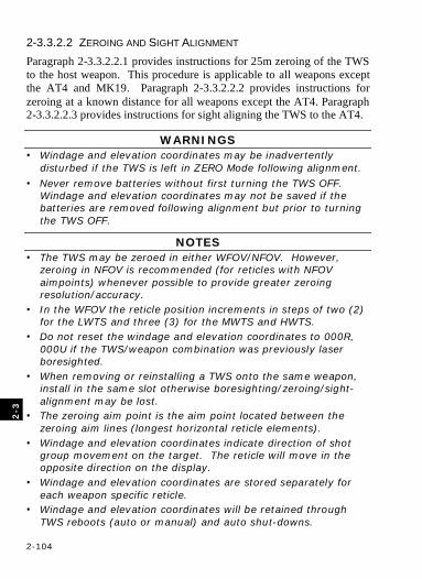
2-104
2
-3
2-3.3.2.2 ZEROING AND SIGHT ALIGNMENT Paragraph 2-3.3.2.2.1 provides instructions for 25m zeroing of the TWS to the host weapon. This procedure is applicable to all weapons except the AT4 and MK19. Paragraph 2-3.3.2.2.2 provides instructions for zeroing at a known distance for all weapons except the AT4. Paragraph 2-3.3.2.2.3 provides instructions for sight aligning the TWS to the AT4.
WARNINGS • Windage and elevation coordinates may be inadvertently
disturbed if the TWS is left in ZERO Mode following alignment.
• Never remove batteries without first turning the TWS OFF. Windage and elevation coordinates may not be saved if the batteries are removed following alignment but prior to turning the TWS OFF.
NOTES • The TWS may be zeroed in either WFOV/NFOV. However,
zeroing in NFOV is recommended (for reticles with NFOV aimpoints) whenever possible to provide greater zeroing resolution/accuracy.
• In the WFOV the reticle position increments in steps of two (2) for the LWTS and three (3) for the MWTS and HWTS.
• Do not reset the windage and elevation coordinates to 000R, 000U if the TWS/weapon combination was previously laser boresighted.
• When removing or reinstalling a TWS onto the same weapon, install in the same slot otherwise boresighting/zeroing/sight-alignment may be lost.
• The zeroing aim point is the aim point located between the zeroing aim lines (longest horizontal reticle elements).
• Windage and elevation coordinates indicate direction of shot group movement on the target. The reticle will move in the opposite direction on the display.
• Windage and elevation coordinates are stored separately for each weapon specific reticle.
• Windage and elevation coordinates will be retained through TWS reboots (auto or manual) and auto shut-downs.
2-105
2-3
2-3.3.2.2.1 25m Battlefield Zeroing
NOTES • The point of aim will always be center of mass on the M16A2
25m zeroing target.
• Offsets vary with weapon. See Table 2-21.
• For shot group movement per click at 25 m, see Table 2-21.
• 25m shot group movement per click scales are provided on the Quick Reference Card.
• Set M2 Bracket range lever to NEAR and hand tighten locking knob.
• Actual displayed reticle scale and position may vary from that illustrated herein, see ¶2-1.1.3.2.
a. Place modified M16A2 25m zeroing target, mounted on thermalized E-type silhouette, at range of 25 meters.
b. Mount the TWS to host weapon per ¶2-3.2. c. Place TWS in operation and make initial adjustments per ¶ 2-3.3.1. d. Select NFOV (momentarily press then release FOV button). e. Advance TWS mode to ZERO (Press >2 Seconds, then release the
MODE button to advance to EMER, repeat to advance to ZERO). f. Select reticle appropriate for weapon used (in Reticle State,
momentarily press then release the FUNCTION switch center pushbutton to advance reticle selection).
g. Set windage and elevation coordinates to 000R, 000U if the TWS/weapon has not previously been laser boresighted (deflect FUNCTION switch left/right, up/down, while in ZERO mode).
h. Assume a good supported firing position. i. Aim center mass at 25m target, and fire three rounds to obtain shot
group. Locate center of shot group (see Figure 2-40). j. Measure distance in windage and elevation from the center of shot
group to the desired point of impact using QRC scales or squares method (see example and Figure 2-40). 1. If center of shot group is above the desired point of impact,
decrease the up (U) elevation setting or increase the down (D)
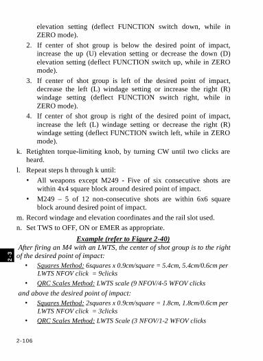
2-106
2
-3
elevation setting (deflect FUNCTION switch down, while in ZERO mode).
2. If center of shot group is below the desired point of impact, increase the up (U) elevation setting or decrease the down (D) elevation setting (deflect FUNCTION switch up, while in ZERO mode).
3. If center of shot group is left of the desired point of impact, decrease the left (L) windage setting or increase the right (R) windage setting (deflect FUNCTION switch right, while in ZERO mode).
4. If center of shot group is right of the desired point of impact, increase the left (L) windage setting or decrease the right (R) windage setting (deflect FUNCTION switch left, while in ZERO mode).
k. Retighten torque-limiting knob, by turning CW until two clicks are heard.
l. Repeat steps h through k until: • All weapons except M249 - Five of six consecutive shots are
within 4x4 square block around desired point of impact. • M249 – 5 of 12 non-consecutive shots are within 6x6 square
block around desired point of impact. m. Record windage and elevation coordinates and the rail slot used. n. Set TWS to OFF, ON or EMER as appropriate.
Example (refer to Figure 2-40) After firing an M4 with an LWTS, the center of shot group is to the right of the desired point of impact:
• Squares Method: 6squares x 0.9cm/square = 5.4cm, 5.4cm/0.6cm per LWTS NFOV click = 9clicks
• QRC Scales Method: LWTS scale (9 NFOV/4-5 WFOV clicks and above the desired point of impact:
• Squares Method: 2squares x 0.9cm/square = 1.8cm, 1.8cm/0.6cm per LWTS NFOV click = 3clicks
• QRC Scales Method: LWTS Scale (3 NFOV/1-2 WFOV clicks
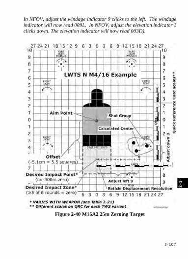
2-107
2-3
In NFOV, adjust the windage indicator 9 clicks to the left. The windage indicator will now read 009L. In NFOV, adjust the elevation indicator 3 clicks down. The elevation indicator will now read 003D).
Figure 2-40 M16A2 25m Zeroing Target
2-108
2
-3
2-3.3.2.2.2 Zeroing at a Known Distance (KD)
WARNING Remove eye from eyecup before firing MK19 machine gun. Recoil
of MK19 machine gun may cause injury to personnel.
NOTES • For shot group movement per click at KD ranges, see Table 2-
23. • When reinstalling a zeroed TWS on the same weapon, install
into the same slot used for zeroing. Failure to do so may result in the TWS no longer being zeroed to the weapon.
• When reinstalling the M2 bracket from a zeroed weapon, zero may not be retained. A field zero should again be performed as soon as possible.
• Actual displayed reticle scale and position may vary from that illustrated herein, see ¶2-1.1.3.2.
a. Select a target at a known distance per Table 2-22. b. Mount the TWS to host weapon per ¶2-3.2. c. Place TWS in operation and make initial adjustments per ¶ 2-3.3.1. d. Select NFOV (momentarily press then release FOV button). e. Advance TWS mode to ZERO (Press >2 Seconds, then release, twice, the
MODE button). f. Select reticle appropriate for weapon being used (Press <2 seconds, then
release the FUNCTION switch center pushbutton to advance reticle selection).
g. Set the windage and elevation coordinates to 000R, 000U if the TWS/weapon has not previously been laser boresighted (deflect FUNCTION switch left/right, up/down, while in ZERO mode).
h. While viewing the target with the TWS, adjust focus, polarity and, as required, ROI, gain and level for an optimum image of target.
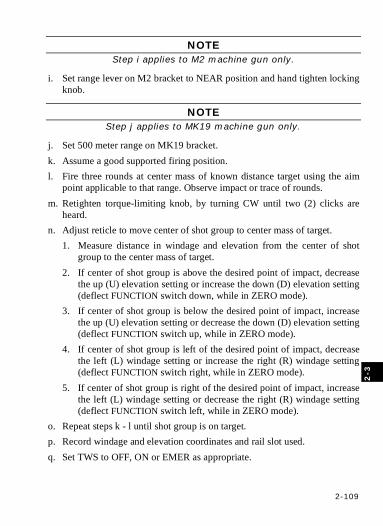
2-109
2-3
NOTE Step i applies to M2 machine gun only.
i. Set range lever on M2 bracket to NEAR position and hand tighten locking knob.
NOTE Step j applies to MK19 machine gun only.
j. Set 500 meter range on MK19 bracket. k. Assume a good supported firing position. l. Fire three rounds at center mass of known distance target using the aim
point applicable to that range. Observe impact or trace of rounds. m. Retighten torque-limiting knob, by turning CW until two (2) clicks are
heard. n. Adjust reticle to move center of shot group to center mass of target.
1. Measure distance in windage and elevation from the center of shot group to the center mass of target.
2. If center of shot group is above the desired point of impact, decrease the up (U) elevation setting or increase the down (D) elevation setting (deflect FUNCTION switch down, while in ZERO mode).
3. If center of shot group is below the desired point of impact, increase the up (U) elevation setting or decrease the down (D) elevation setting (deflect FUNCTION switch up, while in ZERO mode).
4. If center of shot group is left of the desired point of impact, decrease the left (L) windage setting or increase the right (R) windage setting (deflect FUNCTION switch right, while in ZERO mode).
5. If center of shot group is right of the desired point of impact, increase the left (L) windage setting or decrease the right (R) windage setting (deflect FUNCTION switch left, while in ZERO mode).
o. Repeat steps k - l until shot group is on target. p. Record windage and elevation coordinates and rail slot used. q. Set TWS to OFF, ON or EMER as appropriate.
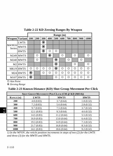
2-110
2
-3
Table 2-22 KD Zeroing Ranges By Weapon Range (m) Weapon Variant 100 200 300 400 500 600 700 800 900 1000
LWTS MWTS M4/M16
Series HWTS
M249 MWTS
M240 MWTS M2 HWTS
MK19 HWTS
M24 HWTS
M107 HWTS
Aim Point Zeroing Range
Table 2-23 Known Distance (KD) Shot Group Movement Per Click SHOT GROUP MOVEMENT PER CLICK (CM @ KD (MOA))
RANGE (M) LWTS MWTS HWTS 200 4.8 (0.83) 3.7 (0.64) 1.8 (0.32) 300 7.2 (0.83) 5.6 (0.64) 2.8 (0.32) 400 9.7 (0.83) 7.5 (0.64) 3.7 (0.32) 500 12.1 (0.83) 9.3 (0.64) 4.6 (0.32) 600 14.5 (0.83) 11.2 (0.64) 5.5 (0.32) 700 16.9 (0.83) 13.0 (0.64) 6.4 (0.32) 800 19.3 (0.83) 14.9 (0.64) 7.3 (0.32) 900 21.7 (0.83) 16.8 (0.64) 8.3 (0.32)
1000 24.1 (0.83) 18.6 (0.64) 9.2 (0.32) 1) In the WFOV, the reticle position increments in steps of two (2) for the LWTS and three (3) for the MWTS and HWTS.
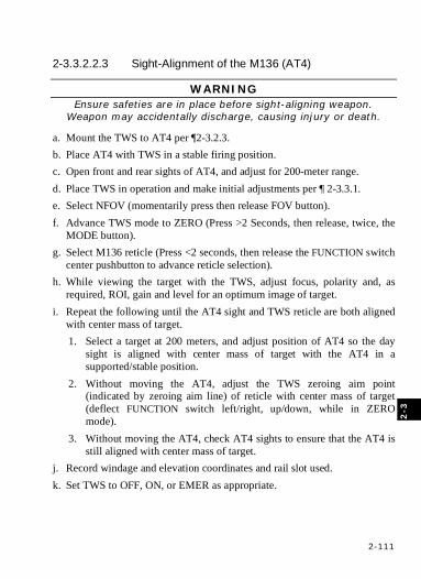
2-111
2-3
2-3.3.2.2.3 Sight-Alignment of the M136 (AT4)
WARNING Ensure safeties are in place before sight-aligning weapon.
Weapon may accidentally discharge, causing injury or death.
a. Mount the TWS to AT4 per ¶2-3.2.3. b. Place AT4 with TWS in a stable firing position. c. Open front and rear sights of AT4, and adjust for 200-meter range. d. Place TWS in operation and make initial adjustments per ¶ 2-3.3.1. e. Select NFOV (momentarily press then release FOV button). f. Advance TWS mode to ZERO (Press >2 Seconds, then release, twice, the
MODE button). g. Select M136 reticle (Press <2 seconds, then release the FUNCTION switch
center pushbutton to advance reticle selection). h. While viewing the target with the TWS, adjust focus, polarity and, as
required, ROI, gain and level for an optimum image of target. i. Repeat the following until the AT4 sight and TWS reticle are both aligned
with center mass of target. 1. Select a target at 200 meters, and adjust position of AT4 so the day
sight is aligned with center mass of target with the AT4 in a supported/stable position.
2. Without moving the AT4, adjust the TWS zeroing aim point (indicated by zeroing aim line) of reticle with center mass of target (deflect FUNCTION switch left/right, up/down, while in ZERO mode).
3. Without moving the AT4, check AT4 sights to ensure that the AT4 is still aligned with center mass of target.
j. Record windage and elevation coordinates and rail slot used. k. Set TWS to OFF, ON, or EMER as appropriate.
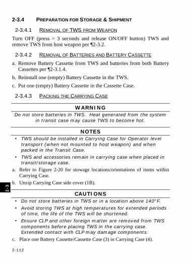
2-112
2
-3
2-3.4 PREPARATION FOR STORAGE & SHIPMENT
2-3.4.1 REMOVAL OF TWS FROM WEAPON Turn OFF (press > 3 seconds and release ON/OFF button) TWS and remove TWS from host weapon per ¶2-3.2.
2-3.4.2 REMOVAL OF BATTERIES AND BATTERY CASSETTE a. Remove Battery Cassette from TWS and batteries from both Battery
Cassettes per ¶2-3.1.4. b. Reinstall one (empty) Battery Cassette in the TWS. c. Put one (empty) Battery Cassette in the Cassette Case.
2-3.4.3 PACKING THE CARRYING CASE
WARNING Do not store batteries in TWS. Heat generated from the system
in transit case may cause TWS to become hot.
NOTES • TWS should be installed in Carrying Case for Operator level
transport (when not mounted to host weapon) and when packed in the Transit Case.
• TWS and accessories remain in carrying case when placed in transit/storage case.
a. Refer to Figure 2-20 for stowage locations/orientations of items within Carrying Case.
b. Unzip Carrying Case side cover (1B).
CAUTIONS • Do not store batteries in TWS or in a location above 140°F.
• Avoid storing TWS at high temperatures for extended periods of time, the life of the TWS will be shortened.
• Ensure CLP and other foreign matter are removed from TWS components before placing TWS in the carrying case. Extended contact with CLP may damage components.
c. Place one Battery Cassette/Cassette Case (3) in Carrying Case (4).
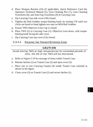
2-113
2-3
d. Place Weapon Bracket (10) (if applicable), Quick Reference Card (6), Operators Technical Manual (5), Lens Cleaning Pen (7), Lens Cleaning Towelettes (8), and Anti-Fog Towelettes (9) in Carrying Case.
e. Zip Carrying Case side cover (1B) closed. f. Tighten the Rail Grabber torque-limiting knob, by turning CW until two
clicks are heard or hand tighten two nuts on M24 Rail Grabber. g. Ensure TWS Objective Lens Cap is closed. h. Place TWS (2) in Carrying Case (1), Objective Lens down, with torque-
limiting knob facing the side cover. i. Zip Carrying Case top cover (1A) closed.
2-3.4.4 PACKING THE TRANSIT/STORAGE CASE
CAUTION Avoid storing TWS at high temperatures for extended periods of
time, the life of the TWS will be shortened.
a. Refer to Figure 2-19 for stowage of items within Transit Case. b. Release latches (1) on Transit Case (2) and open cover (3). c. Place one or two Carrying Case(s) (4) inside Transit Case oriented as
shown in the figure. d. Close cover (3) on Transit Case (2) and secure latches (1).
2-114
SECTION 4 OPERATION UNDER UNUSUAL CONDITIONS 2-4.1 OPERATING IN INCLEMENT WEATHER/ENVIRONMENT
2-4.1.1 EXTREME COLD
WARNING Do not expose batteries to open flame or high temperatures.
Batteries may explode or leak and cause personnel injury.
CAUTION Only use the Anti-fog Towelette on the Eyepiece Lens. DO NOT USE ANTI-FOG TOWELETTE ON THE OBJECTIVE LENS. The
anti-fog compound will degrade the IR transmission of the Objective Lens and is very difficult to remove.
NOTES • Battery-life performance will degrade significantly under cold
temperatures. NiMH and alkaline batteries may not function or may provide unacceptable battery life performance under extreme cold conditions.
• During cold temperatures while in non-use, loaded battery cassettes should be kept close to the body to keep warm. Batteries will last longer if batteries are warm.
• Avoid exposing lenses to any source of moisture during cold weather. Lens may fog up or frost over.
• Use only L91 Batteries when operating at cold temperatures.
• At extreme cold temperatures the “COLD START” indicator may be displayed on the start-up screen indicating the TWS may take longer to start up to allow the display to come up to operating temperature.
The TWS can operate down to low temperatures of -46°C (-51°F). To minimize fogging/frosting of lenses, perform the following procedures: 2-4.1.1.1 OBJECTIVE LENS Clean Objective Lens per ¶3-2.3.
2-4.1.1.2 EYEPIECE LENS a. Clean Eyepiece Lens per ¶3-2.3. b. Apply antifogging compound to Eyepiece Lens only per ¶3-2.4.
2-115
2-4.1.2 EXTREME HEAT
CAUTIONS • Do not store batteries in TWS or in a location above 140°F. • Avoid storing TWS at high temperatures for extended
periods of time, the life of the TWS will be shortened.
NOTE A hot barrel or front sight post within the FOV will produce an out
of focus hot image the lower portion of the display that will appear as an image non-uniformity or “blooming”. The hotter the
barrel/front sight post and the wider the FOV the more pronounced the effect. Thus the effect will be more pronounced with the LWTS and MWTS than with the HWTS, and will be more pronounced in the WFOV than in the NFOV. Selecting AUTO 1 or AUTO 2 conditions will minimize the impact on the balance of the
image. AUTO3 should be avoided if this condition exists.
The TWS can be operated up to a high temperature of 49 °C (120 °F).
2-4.1.3 RAIN, FOG, OR HUMIDITY
WARNING Do not expose batteries to water. Batteries may short circuit and/or flammable or noxious gas may be released that may
cause a fire or injury to personnel.
CAUTION Only use the Anti-fog Towelette on the Eyepiece lens. DO NOT USE ANTI-FOG TOWELETTE ON THE OBJECTIVE LENS. The
anti-fog compound will degrade the IR transmission of the Objective Lens and is very difficult to remove.
NOTES • Avoid exposing lenses to any source of moisture during cold
weather. Lens may fog up or frost over. • Range performance will degrade as atmospheric moisture
content/precipitation increases.
2-116
In rainy, foggy or humid conditions, observe the following precautions: a. To prevent fogging of lenses see ¶3-2.4. b. Dry all parts thoroughly after exposure to moisture. c. Keep Carrying Case closed except to remove or replace equipment. d. Do not store TWS in a wet or damp Carrying Case.
2-4.1.4 SALT WATER
WARNING Do not expose batteries to water. Batteries may short circuit and/or flammable or noxious gas may be released that may
cause a fire or injury to personnel.
In salt water areas, observe the following precautions: a. After exposure to salt water, clean all components with fresh water. b. Dry all parts thoroughly after removing all traces of salt water. c. Do not store TWS in a wet or damp Carrying Case.
2-4.1.5 DUST OR SAND Avoid operating TWS under these conditions, if possible. If operation is necessary, observe the following precautions: a. Avoid prolonged pointing of the TWS into wind blown dust and sand to
prevent pitting or scratching of the Objective Lens. b. Cover as much of the TWS as possible to prevent damage to external
surfaces. c. Keep Carrying Case closed except to remove or replace equipment. d. Clean the Eyepiece and Objective Lenses as required (¶3-2.3).
2-4.1.6 MUD After exposure to mud, clean TWS exterior (¶3-2.1) and lenses (¶3-2.3).
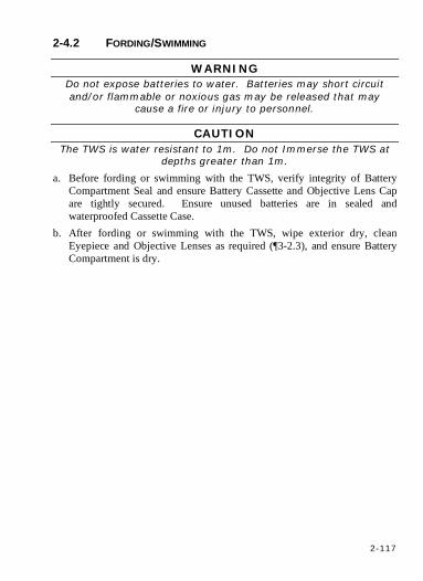
2-117
2-4.2 FORDING/SWIMMING
WARNING Do not expose batteries to water. Batteries may short circuit and/or flammable or noxious gas may be released that may
cause a fire or injury to personnel.
CAUTION The TWS is water resistant to 1m. Do not Immerse the TWS at
depths greater than 1m.
a. Before fording or swimming with the TWS, verify integrity of Battery Compartment Seal and ensure Battery Cassette and Objective Lens Cap are tightly secured. Ensure unused batteries are in sealed and waterproofed Cassette Case.
b. After fording or swimming with the TWS, wipe exterior dry, clean Eyepiece and Objective Lenses as required (¶3-2.3), and ensure Battery Compartment is dry.

2-118
2-4.3 NUCLEAR, BIOLOGICAL AND CHEMICAL (NBC) DECONTAMINATION
WARNING Unit deliberate decon SOP must be followed as the following
procedures do not provide total decontamination. Protective mask and gloves should be worn when handling until total
decontamination is completed by the decon lab.
NOTE The TWS may be used while wearing MOPP IV (Mission Oriented Protective Posture) gear. Discard the entire carrying case if it is
contaminated.
2-4.3.1 CHEMICAL GROSS LIQUID DECONTAMINATION a. Remove and discard contaminated Eyecup, Objective Lens Cap, Battery
Cassettes, Battery Compartment Seal, and I/O Cap before returning TWS to next higher level of maintenance.
b. Decontaminate with M295 Decontamination Kit or by using a cloth and stiff bristle plastic brush with 5-percent solution of sodium hypochlorite and clean with a cloth dampened with soapy water, followed by fresh clean water. Clean all external surfaces thoroughly. Pay special attention to the difficult to reach areas (controls/buttons).
c. Dry all parts thoroughly. d. Clean lenses per ¶3-2.3. e. Using the M256 kit, verify successful decontamination or that chemical
contamination is still present. If decontamination was successful, go to step h. If still contaminated, repeat steps b-d and then go to step f.
f. Retest for contamination using the M256 kit. If decontamination was successful go to step h. If the sight is still contaminated, repeat steps b-d and then go to step g.
g. Retest for contamination using the M256 kit. If decontamination was successful go to step h. If the sight is still contaminated, dispose of the sight per unit SOP.
2-119
h. Turn in TWS to next higher level of maintenance for 1) Eyecup, Objective Lens Cap, and Battery Compartment Seal replacement, and 2) decontamination of the lens assemblies with alcohol.
2-4.3.2 BIOLOGICAL DECONTAMINATION a. Remove and discard contaminated Eyecup, Objective Lens Cap, Battery
Cassettes and Battery Compartment Seal before returning TWS to next higher level of maintenance.
b. Use a cloth and stiff bristle plastic brush, dampened with High Test Hypochlorite (HTH) or household bleach, to wash the system, followed by a fresh clean water rinse.
c. Dry all parts thoroughly. d. Clean lens per ¶3-2.3 e. Tag TWS as contaminated prior to returning to next higher level of
maintenance. f. Turn in TWS to next higher level of maintenance for 1) Eyecup,
Objective Lens Cap, and Battery Compartment Seal replacement, and 2) decontamination of the lens assemblies with alcohol.
2-4.3.3 NUCLEAR DECONTAMINATION a. Remove and discard contaminated Eyecup, Objective Lens Cap, Battery
Cassettes and Battery Compartment Seal before returning TWS to next higher level of maintenance.
b. Remove contaminates from TWS with a vacuum or brush, and rinse in soapy water, followed by fresh, clean water.
c. Dry all parts thoroughly. d. Clean lenses per ¶3-2.3. e. Tag TWS as contaminated prior to returning to next higher level of
maintenance. f. Turn in TWS to next higher level of maintenance for 1) Eyecup,
Objective Lens Cap, and Battery Compartment Seal replacement, and 2) decontamination of the lens assemblies with alcohol.
2-120
2-4.4 EMERGENCY PROCEDURES
WARNING The TWS is not light secure in Emergency mode. Use Emergency
mode only if circumstances do not require light discipline.
NOTES • Display will be forced on regardless of Eyecup position while
in Emergency mode.
• EMER indicator will be displayed while in the Emergency mode.
• When in emergency mode, the system can only be calibrated by using the Polarity button.
• Battery life will be reduced in the Emergency mode.
If an emergency situation exists where Operator cannot activate the TWS due to a missing or damaged Eyecup or faulty Standby Override Switch, and circumstances do not require light discipline, place TWS in EMER mode. Remove TWS from EMER mode as soon as conditions permit. a. Place TWS in operation per ¶2-3.3. b. Set the TWS to the EMER mode (press >2 seconds and release the
MODE button to advance the TWS to the EMER Mode). c. To optimize the thermal scene, initiate a calibration by pressing <3
seconds, then releasing the ON/OFF button (system will not permit calibration again for 20 seconds).
d. When circumstances permit forward TWS to next higher level of maintenance.
3-1
CHAPTER 3 OPERATOR MAINTENANCE INSTRUCTIONS
SECTION 1 OPERATORʼS TROUBLESHOOTING PROCEDURES
3-1.1 TROUBLESHOOTING TABLE This table lists the common malfunctions that may occur with the TWS. Perform the tests, inspections, and corrective actions in the order they appear in the Troubleshooting Table (Table 3-1). Table 3-1 does not list all the malfunctions that may occur, all the tests and inspections needed to find the fault, or all the corrective actions needed to correct the fault. If the equipment malfunction is not listed or the actions listed do not correct the fault, forward the entire system (include all items in Appendix B), to next higher level of maintenance.
3-1
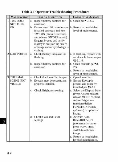
3-2
Table 3-1 Operator Troubleshooting Procedures MALFUNCTION TEST OR INSPECTION CORRECTIVE ACTION
a. Inspect battery contacts for corrosion.
a. Clean per ¶ 3-2.5. 1 TWS DOES NOT TURN ON b. Ensure new L91 batteries are
installed correctly and turn TWS ON (Press >3 seconds and release ON/OFF button). Engage Eyecup and verify display is on (start-up screen or image and/or symbology is visible).
b. Return to next higher level of maintenance.
a. Check Battery Indicator for flashing.
a. If flashing, replace with serviceable batteries per ¶2-3.1.4.
b. Inspect battery contacts for corrosion.
b. Clean contacts per ¶3-2.5.
2 LOW POWER
c. c. Return to next higher level of maintenance.
a. Check that Lens Cap is open. a. Open Lens Cap. b. Eyecup must be present and
properly installed. b. Ensure Eyecup is
present and properly installed per ¶3-2.2.
c. Check Brightness setting. c. Select the Display State (Press <2 seconds and release MODE Switch). Adjust Brightness function (deflect FUNCTION switch up/down) to optimize image.
d. Check Gain and Level settings.
d. Activate Auto Reset/ROI Select (momentarily center press FUNCTION switch to optimize image.
3 THERMAL SCENE NOT VISIBLE
e. e. Return to next higher level of maintenance.
3
-1
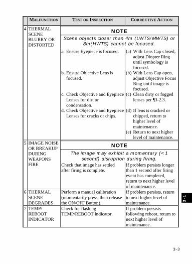
3-3
MALFUNCTION TEST OR INSPECTION CORRECTIVE ACTION
NOTE Scene objects closer than 4m (LWTS/MWTS) or
8m(HWTS) cannot be focused.
a. Ensure Eyepiece is focused.
(a) With Lens Cap closed, adjust Diopter Ring until symbology is focused.
b. Ensure Objective Lens is focused.
(b) With Lens Cap open, adjust Objective Focus Ring until image is focused.
c. Check Objective and Eyepiece Lenses for dirt or condensation.
(c) Clean dirty or fogged lenses per ¶3-2.3.
d. Check Objective and Eyepiece Lenses for cracks or chips.
(d) If lens is cracked or chipped, return to higher level of maintenance.
4 THERMAL SCENE BLURRY OR DISTORTED
(e) Return to next higher level of maintenance.
NOTE The image may exhibit a momentary (<1
second) disruption during firing.
5 IMAGE NOISE OR BREAKUP DURING WEAPONS FIRE Check that image has settled
after firing is complete. If problem persists longer than 1 second after firing event has completed, return to next higher level of maintenance.
6 THERMAL SCENE DEGRADES
Perform a manual calibration (momentarily press, then release the ON/OFF Button).
If problem persists, return to next higher level of maintenance.
7 TEMP/ REBOOT INDICATOR
Check for flashing TEMP/REBOOT indicator.
If problem persists following reboot, return to next higher level of maintenance.
3-1
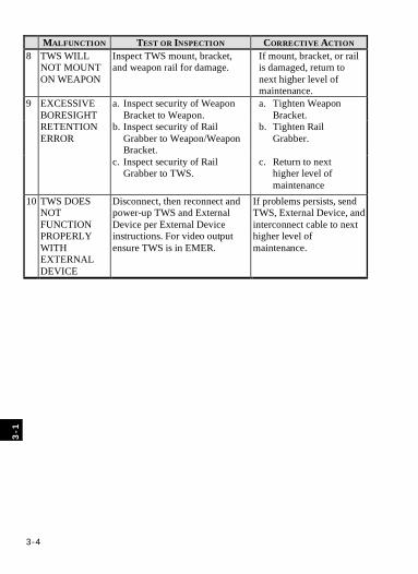
3-4
MALFUNCTION TEST OR INSPECTION CORRECTIVE ACTION 8 TWS WILL
NOT MOUNT ON WEAPON
Inspect TWS mount, bracket, and weapon rail for damage.
If mount, bracket, or rail is damaged, return to next higher level of maintenance.
a. Inspect security of Weapon Bracket to Weapon.
a. Tighten Weapon Bracket.
b. Inspect security of Rail Grabber to Weapon/Weapon Bracket.
b. Tighten Rail Grabber.
9 EXCESSIVE BORESIGHT RETENTION ERROR
c. Inspect security of Rail Grabber to TWS.
c. Return to next higher level of maintenance
10
TWS DOES NOT FUNCTION PROPERLY WITH EXTERNAL DEVICE
Disconnect, then reconnect and power-up TWS and External Device per External Device instructions. For video output ensure TWS is in EMER.
If problems persists, send TWS, External Device, and interconnect cable to next higher level of maintenance.
3
-1
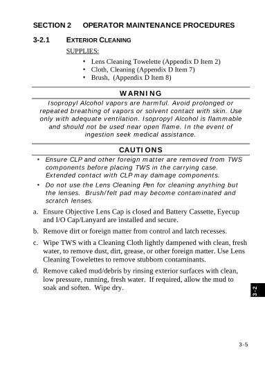
3-5
SECTION 2 OPERATOR MAINTENANCE PROCEDURES
3-2.1 EXTERIOR CLEANING SUPPLIES:
• Lens Cleaning Towelette (Appendix D Item 2) • Cloth, Cleaning (Appendix D Item 7) • Brush, (Appendix D Item 8)
WARNING Isopropyl Alcohol vapors are harmful. Avoid prolonged or
repeated breathing of vapors or solvent contact with skin. Use only with adequate ventilation. Isopropyl Alcohol is flammable
and should not be used near open flame. In the event of ingestion seek medical assistance.
CAUTIONS • Ensure CLP and other foreign matter are removed from TWS
components before placing TWS in the carrying case. Extended contact with CLP may damage components.
• Do not use the Lens Cleaning Pen for cleaning anything but the lenses. Brush/felt pad may become contaminated and scratch lenses.
a. Ensure Objective Lens Cap is closed and Battery Cassette, Eyecup and I/O Cap/Lanyard are installed and secure.
b. Remove dirt or foreign matter from control and latch recesses. c. Wipe TWS with a Cleaning Cloth lightly dampened with clean, fresh
water, to remove dust, dirt, grease, or other foreign matter. Use Lens Cleaning Towelettes to remove stubborn contaminants.
d. Remove caked mud/debris by rinsing exterior surfaces with clean, low pressure, running, fresh water. If required, allow the mud to soak and soften. Wipe dry.
3-2
3-6
3-2.2 EYECUP REMOVAL/REINSTALLATION
NOTE Eyecup removal/reinstallation procedures are provided to
facilitate cleaning of the Eyepiece lens at the Operator level. Repairs requiring replacement of the Eyecup are next higher level
of maintenance actions.
Refer to Figures 3-1a thru g.
3-2.2.1 REMOVAL Remove Eyecup (1) from Eyepiece (2). a. As illustrated in Figures 3-1a and b, rotate Retaining Ring (3) CW to
loosen until it disengages from the Flange (4) or contacts the Diopter Ring (5). When loosened, the Retaining Ring should completely clear the Eyecup lip (1a).
b. As illustrated in Figures 3-1b and c, grasp the Eyecup (1) anywhere along the circumference of point (1b) and pull out and back to peel the Eyecup (1) from the Flange (4).
3-2.2.2 REINSTALLATION Reinstall Eyecup (1) to Eyepiece (2). a. As illustrated in Figure 3-1d, inspect the Eyecup (1) for presence of
both Magnets (6). If missing, continue reinstallation and return the TWS to next higher level of maintenance.
b. As illustrated in Figures 3-1d, inspect Eyepiece Lens (7) and clean as required per ¶3-2.3. If the lens is cracked or internal condensation is present, continue reinstallation and return the TWS to next higher level of maintenance.
c. As illustrated in Figures 3-1e and f, orient the Eyecup (1) so the wrap-around (1c) will be positioned on the outside of the Operator’s face (on the right for right-eyed, and on the left for left-eyed Operators), and so the Eyecup keying tabs (1d) align with the Flange keying slots (4a). Manipulate the Eyecup Lip (1a) into the Flange
3
-2
3-7
groove (4b) until fully seated around the entire circumference with Eyecup keying tabs seated in the Flange keying slots.
d. As illustrated in Figures 3-1a and 3-1g, rotate Retaining Ring (3) to tighten until it is fully seated against the Eyecup (1). When tightened, the Retaining Ring should completely cover the Eyecup lip (1a).
e. Inspect the assembly to ensure that: As illustrated in Figure 3-1g: • The wrap-around (1c) is positioned on the outside of the
Operator’s face (on the right for right-eyed, and on the left for left-eyed Operators) and vent holes (1e) are positioned at the 6 and 12 o’clock positions.
• The Retaining Ring (3) is fully seated over the Eyecup lip (1a). f. Verify Eyecup is functioning properly per PMCS Table 2-17 step 9.
3-2
3-8
Figure 3-1a Eyecup Removal/Reinstallation
Figure 3-1b Eyecup Removal/Reinstallation
Figure 3-1c Eyecup Removal/Reinstallation
Figure 3-1d Eyecup Removal/Reinstallation
3
-2
3-9
Figure 3-1e Eyecup Removal/Reinstallation
Figure 3-1f Eyecup Removal/Reinstallation
Figure 3-1g Eyecup Removal/Reinstallation
3
-2

3-10
3-2.3 LENS CLEANING SUPPLIES:
• Lens Cleaner Pen (Appendix D-2 Item 1) • Lens Cleaning Towelettes (Appendix D-2 Item 2)
CAUTIONS • Clean Lenses only when required. Excessive cleaning may
damage lens surfaces degrading TWS performance.
• Use of unauthorized cleaning materials or techniques may damage lens surfaces degrading TWS performance.
• Avoid excessive pressure when wiping lens. Foreign matter on lens may scratch lens when wiped off.
• Do not use the Lens Cleaning Pen for cleaning anything but the lenses. Brush/felt pad may become contaminated and scratch lenses.
• Do not wipe, chip or rub mud off lens. Lens surface may be damaged degrading TWS performance.
NOTE This procedure applies to both the Objective and Eyepiece
Lenses.
a. Open Objective Lens Cap or remove Eyecup as applicable. b. Inspect lens surfaces. If lens surfaces are clean, stop - do not perform
this procedure. If lens surfaces have caked mud or debris proceed to step c, else proceed to step d. For removing light fingerprints only, skip to step i.
c. Ensure Battery Cassette is installed and secure. Rinse lens surfaces with clean, low pressure, running, fresh water. Allow the water to remove the mud. If required, allow the mud to soak and soften. Allow lens to air dry.
d. Remove Lens Cleaner Pen and Lens Cleaning Towelettes from Carrying Case.
e. Gently blow off excessive sand and dust from lens surface.
3
-2
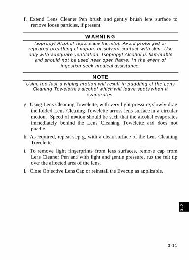
3-11
f. Extend Lens Cleaner Pen brush and gently brush lens surface to remove loose particles, if present.
WARNING Isopropyl Alcohol vapors are harmful. Avoid prolonged or
repeated breathing of vapors or solvent contact with skin. Use only with adequate ventilation. Isopropyl Alcohol is flammable
and should not be used near open flame. In the event of ingestion seek medical assistance.
NOTE Using too fast a wiping motion will result in puddling of the Lens
Cleaning Towelette’s alcohol which will leave spots when it evaporates.
g. Using Lens Cleaning Towelette, with very light pressure, slowly drag the folded Lens Cleaning Towelette across lens surface in a circular motion. Speed of motion should be such that the alcohol evaporates immediately behind the Lens Cleaning Towelette and does not puddle.
h. As required, repeat step g, with a clean surface of the Lens Cleaning Towelette.
i. To remove light fingerprints from lens surfaces, remove cap from Lens Cleaner Pen and with light and gentle pressure, rub the felt tip over the affected area of the lens.
j. Close Objective Lens Cap or reinstall the Eyecup as applicable.
3-2
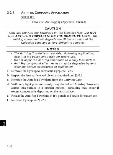
3-12
3-2.4 ANTI-FOG COMPOUND APPLICATION SUPPLIES:
• Towelette, Anti-fogging (Appendix D Item 3)
CAUTION Only use the Anti-fog Towelette on the Eyepiece lens. DO NOT
USE ANTI-FOG TOWELETTE ON THE OBJECTIVE LENS. The anti-fog compound will degrade the IR transmission of the
Objective Lens and is very difficult to remove.
NOTES • The Anti-fog Towelette is reusable. Following application,
seal it in it’s pouch and retain for future use. • Do not apply the Anti-fog compound to a dirty lens surface. • Anti-Fog compound effectiveness may be degraded by lens
cleaning actions subsequent to application.
a. Remove the Eyecup to access the Eyepiece Lens. b. Inspect the lens surface and clean, as required per ¶3-2.3. c. Remove the Anti-fog Towelette from the Carrying Case. d. With very light pressure, slowly drag the folded Anti-fog Towelette
across lens surface in a circular motion. Streaking may occur if excess compound is deposited on the lens surface.
e. Reseal the Anti-fog Towelette in it’s pouch and retain for future use. f. Reinstall Eyecup per ¶3-2.2.
3
-2
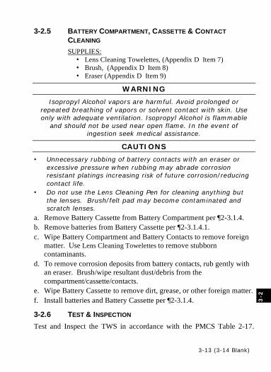
3-13
3-2.5 BATTERY COMPARTMENT, CASSETTE & CONTACT CLEANING SUPPLIES:
• Lens Cleaning Towelettes, (Appendix D Item 7) • Brush, (Appendix D Item 8) • Eraser (Appendix D Item 9)
WARNING
Isopropyl Alcohol vapors are harmful. Avoid prolonged or repeated breathing of vapors or solvent contact with skin. Use only with adequate ventilation. Isopropyl Alcohol is flammable
and should not be used near open flame. In the event of ingestion seek medical assistance.
CAUTIONS
• Unnecessary rubbing of battery contacts with an eraser or excessive pressure when rubbing may abrade corrosion resistant platings increasing risk of future corrosion/reducing contact life.
• Do not use the Lens Cleaning Pen for cleaning anything but the lenses. Brush/felt pad may become contaminated and scratch lenses.
a. Remove Battery Cassette from Battery Compartment per ¶2-3.1.4. b. Remove batteries from Battery Cassette per ¶2-3.1.4.1. c. Wipe Battery Compartment and Battery Contacts to remove foreign
matter. Use Lens Cleaning Towelettes to remove stubborn contaminants.
d. To remove corrosion deposits from battery contacts, rub gently with an eraser. Brush/wipe resultant dust/debris from the compartment/cassette/contacts.
e. Wipe Battery Cassette to remove dirt, grease, or other foreign matter. f. Install batteries and Battery Cassette per ¶2-3.1.4.
3-2.6 TEST & INSPECTION Test and Inspect the TWS in accordance with the PMCS Table 2-17.
3-2
3-13 (3-14 Blank)

3-14

A-1
APPENDIX A REFERENCES
A-1 SCOPE This Appendix lists all forms, field manuals, technical manuals and miscellaneous publications referenced in this manual.
A-2 FORMS DA Form 2028 Recommended Changes to Publications and
Blank Forms
DA Form 5988-E Equipment Maintenance and Inspection Worksheet
DA Form 5990-E Preventative Maintenance Schedule and Record
DA PAM 750-8 The Army Maintenance Management System (TAMMS) User Manual
SF 368 The Army Product Quality Deficiency Report
A-3 TECHNICAL MANUALS TM 9-5860-226-13&P Operator’s Manual for AN/PEM-1 Laser
Borelight System (LBS-300) TM 750-244-2 Procedures for Destruction of Electronic
Materiel to Prevent Enemy Use (Electronics Command)
TM 4700-15/1 Ground Equipment Records Procedures

A-2
A-4 OTHER PUBLICATIONS CTA 8-100 Army Medical Department Expendable/
Durable Items CTA 50-970 Expendable/Durable Items TB 43-0134 Battery Disposition/Disposal Handbook FM 4-25.11 First Aid
B-1
APPENDIX B COMPONENTS OF END ITEM (COEI) & BASIC ISSUE
ITEMS (BII) B-1 INTRODUCTION
B-1.1 SCOPE This appendix lists components of the end item and basic issue items for the TWS to help you inventory the items for safe and efficient operation of the equipment.
B-1.1.1 GENERAL The Components of End Item and Basic Issue Items Lists are divided into the following sections: a. Section II, Components of End Item. This listing is for information
purposes only, and is not authority to requisition replacements. These items are part of the TWS, but they are to be removed and separately packaged for transportation or shipment. As part of the end item, these items must be with the end item whenever it is issued or transferred between property accounts. Illustrations are furnished to help you find and identify the items.
b. Section III, Basic Issue Items. These essential items are required to place the TWS in operation, operate it, and to do emergency repairs. Although shipped separately packaged, BII must be with the TWS during operation and when it is transferred between property accounts. Listing these items is your authority to request/requisition them for replacement based on authorization of the end item by the TOE/MTOE. Illustrations are furnished to help you find and identify the items.
B-2
B-1.1.2 EXPLANATION OF COLUMNS Column (1), Illus Number. This column gives you the number of the item illustrated. Column (2), National Stock Number. This column identifies the National Stock Number (NSN) of the item to be used for requisitioning purposes. Column (3), Description and Usable On Code. This column identifies the Federal item name (in all capital letters) followed by a minimum description when needed. The last line below the description is the CAGE code (Commercial And Government Entity code) (in parenthesis) and the part number. If the item you need is not the same for different models of the equipment, a Usable On Code (UOC) will appear on the right side of the description column on the same line as the part number. These codes are identified below:
CODE USED ON 81N Sight, Thermal AN/PAS-13C(V)1 81P Sight, Thermal AN/PAS-13C(V)2 81Q Sight, Thermal AN/PAS-13C(V)3
Column (4), U/I (Unit of Issue). This column indicates how the item is issued for the NSN shown in column (2). Column (5), Qty Rqd. This column indicates the quantity required.
B-3
B-2 COMPONENTS OF END ITEM
B-4
(1) ILLUS NO.
(2) NATIONAL
STOCK NUMBER
(3) DESCRIPTION (REF DES) USABLE ON CAGE & PART NUMBER CODE
(4)
U/I
(5) QTY REC.
1 SIGHT,THERMAL 81N (LIGHT WEAPON THERMAL SIGHT) (LWTS) (81395) 21102336-102, or (81395) 21102336-101
EA 1
2 SIGHT,THERMAL 81P (MEDIUM WEAPON THERMAL SIGHT) (MWTS) (81395) 21102337-102, or (81395) 21102337-101
EA 1
3 SIGHT,THERMAL 81Q (HEAVY WEAPON THERMAL SIGHT) (HWTS) (81395) 21102338-102, or (81395) 21102338-101
EA 1
4 1240-01-529-7373 CASE,OPTICAL INSTRUMENT 81N (CARRYING CASE) (81395) 8411043-1, or (81395) 21102487-101
EA 1
5 1240-01-529-7508
CASE,OPTICAL INSTRUMENT 81P (CARRYING CASE) (81395) 8411043-2 or (81395) 21102487-102
EA 1
6 1240-01-529-7733
CASE,OPTICAL INSTRUMENT 81Q (CARRYING CASE) (81395) 8411043-3 or (81395) 21102487-103
EA 1
7 6160-01-529-3096 TRAY,BATTERY 81N (BATTERY CASSETTE) (81395) 8418730-2, or (81395) 8418730-1, or (81395) 8399636-1, or
EA 1*
8 6160-01-529-3942 TRAY,BATTERY 81P (BATTERY CASSETTE) 81Q (81395) 8418859-2, or (81395) 8418859-1, or (81395) 8399637-1, or
EA 1*
9 6160-01-529-6370 CASE,BATTERY ASSEMBLY 81N (CASSETTE CASE) (81395) 8401459-1
EA 1
10 6160-01-529-6447 CASE,BATTERY ASSEMBLY 81P (CASSETTE CASE) 81Q (81395) 8401460-1
EA 1
* 1 spare, plus one as part of each TWS
B-3 BASIC ISSUE ITEMS & COLLATERAL MATERIAL
1
(1) ILLUS NO.
(2) NATIONAL
STOCK NUMBER
(3) DESCRIPTION USABLE ON CAGE & PART NUMBER CODE
(4)
U/I
(5) QTY REC.
1 TECHNICAL MANUAL, OPERATORSIGHT, THERMAL (TM 11-5855-316-10)
EA 1
B-5 (B-6 Blank)

B-2
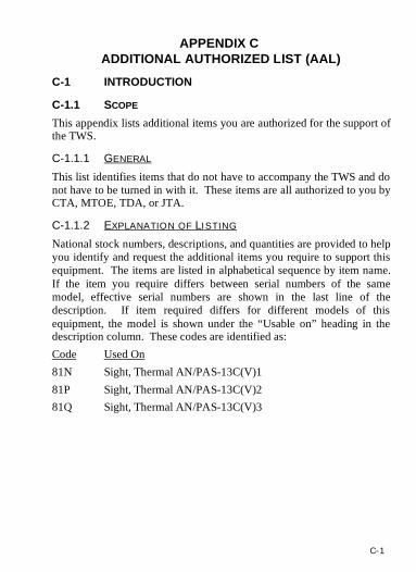
C-1
APPENDIX C ADDITIONAL AUTHORIZED LIST (AAL)
C-1 INTRODUCTION
C-1.1 SCOPE This appendix lists additional items you are authorized for the support of the TWS.
C-1.1.1 GENERAL This list identifies items that do not have to accompany the TWS and do not have to be turned in with it. These items are all authorized to you by CTA, MTOE, TDA, or JTA.
C-1.1.2 EXPLANATION OF LISTING National stock numbers, descriptions, and quantities are provided to help you identify and request the additional items you require to support this equipment. The items are listed in alphabetical sequence by item name. If the item you require differs between serial numbers of the same model, effective serial numbers are shown in the last line of the description. If item required differs for different models of this equipment, the model is shown under the “Usable on” heading in the description column. These codes are identified as: Code Used On 81N Sight, Thermal AN/PAS-13C(V)1 81P Sight, Thermal AN/PAS-13C(V)2 81Q Sight, Thermal AN/PAS-13C(V)3
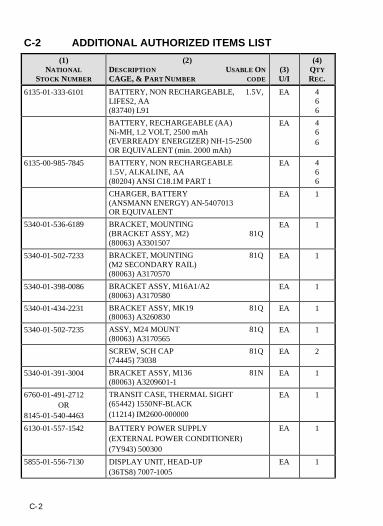
C-2
C-2 ADDITIONAL AUTHORIZED ITEMS LIST (1)
NATIONAL STOCK NUMBER
(2) DESCRIPTION USABLE ON CAGE, & PART NUMBER CODE
(3) U/I
(4) QTY REC.
6135-01-333-6101 BATTERY, NON RECHARGEABLE, 1.5V, LIFES2, AA (83740) L91
EA 4 6 6
BATTERY, RECHARGEABLE (AA) Ni-MH, 1.2 VOLT, 2500 mAh (EVERREADY ENERGIZER) NH-15-2500 OR EQUIVALENT (min. 2000 mAh)
EA 4 6 6
6135-00-985-7845 BATTERY, NON RECHARGEABLE 1.5V, ALKALINE, AA (80204) ANSI C18.1M PART 1
EA 4 6 6
CHARGER, BATTERY (ANSMANN ENERGY) AN-5407013 OR EQUIVALENT
EA 1
5340-01-536-6189
BRACKET, MOUNTING (BRACKET ASSY, M2) 81Q (80063) A3301507
EA 1
5340-01-502-7233 BRACKET, MOUNTING 81Q (M2 SECONDARY RAIL) (80063) A3170570
EA 1
5340-01-398-0086 BRACKET ASSY, M16A1/A2 (80063) A3170580
EA 1
5340-01-434-2231 BRACKET ASSY, MK19 81Q (80063) A3260830
EA 1
5340-01-502-7235 ASSY, M24 MOUNT 81Q (80063) A3170565
EA 1
SCREW, SCH CAP 81Q (74445) 73038
EA 2
5340-01-391-3004 BRACKET ASSY, M136 81N (80063) A3209601-1
EA 1
6760-01-491-2712 OR
8145-01-540-4463
TRANSIT CASE, THERMAL SIGHT (65442) 1550NF-BLACK (11214) IM2600-000000
EA 1
6130-01-557-1542 BATTERY POWER SUPPLY (EXTERNAL POWER CONDITIONER) (7Y943) 500300
EA 1
5855-01-556-7130 DISPLAY UNIT, HEAD-UP (36TS8) 7007-1005
EA 1
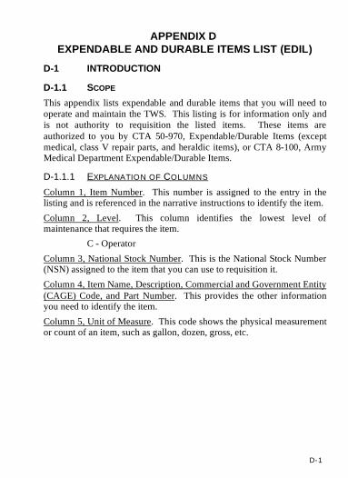
D-1
APPENDIX D EXPENDABLE AND DURABLE ITEMS LIST (EDIL)
D-1 INTRODUCTION
D-1.1 SCOPE This appendix lists expendable and durable items that you will need to operate and maintain the TWS. This listing is for information only and is not authority to requisition the listed items. These items are authorized to you by CTA 50-970, Expendable/Durable Items (except medical, class V repair parts, and heraldic items), or CTA 8-100, Army Medical Department Expendable/Durable Items.
D-1.1.1 EXPLANATION OF COLUMNS Column 1, Item Number. This number is assigned to the entry in the listing and is referenced in the narrative instructions to identify the item. Column 2, Level. This column identifies the lowest level of maintenance that requires the item. C - Operator Column 3, National Stock Number. This is the National Stock Number (NSN) assigned to the item that you can use to requisition it. Column 4, Item Name, Description, Commercial and Government Entity (CAGE) Code, and Part Number. This provides the other information you need to identify the item. Column 5, Unit of Measure. This code shows the physical measurement or count of an item, such as gallon, dozen, gross, etc.
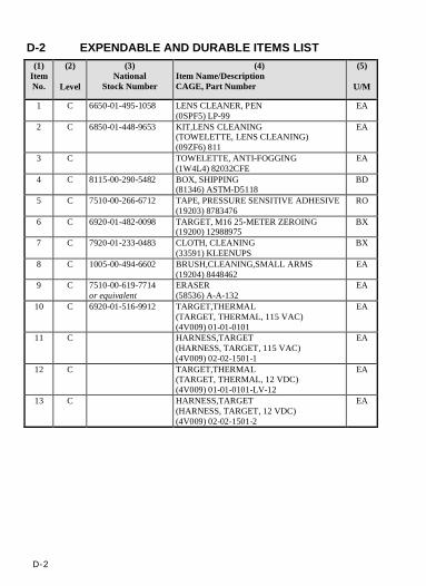
D-2
D-2 EXPENDABLE AND DURABLE ITEMS LIST (1)
Item No.
(2)
Level
(3) National
Stock Number
(4) Item Name/Description CAGE, Part Number
(5)
U/M
1 C 6650-01-495-1058 LENS CLEANER, PEN (0SPF5) LP-99
EA
2 C 6850-01-448-9653 KIT,LENS CLEANING (TOWELETTE, LENS CLEANING) (09ZF6) 811
EA
3 C TOWELETTE, ANTI-FOGGING (1W4L4) 82032CFE
EA
4 C 8115-00-290-5482 BOX, SHIPPING (81346) ASTM-D5118
BD
5 C 7510-00-266-6712 TAPE, PRESSURE SENSITIVE ADHESIVE (19203) 8783476
RO
6 C 6920-01-482-0098 TARGET, M16 25-METER ZEROING (19200) 12988975
BX
7 C 7920-01-233-0483 CLOTH, CLEANING (33591) KLEENUPS
BX
8 C 1005-00-494-6602 BRUSH,CLEANING,SMALL ARMS (19204) 8448462
EA
9 C 7510-00-619-7714 or equivalent
ERASER (58536) A-A-132
EA
10 C 6920-01-516-9912 TARGET,THERMAL (TARGET, THERMAL, 115 VAC) (4V009) 01-01-0101
EA
11 C HARNESS,TARGET (HARNESS, TARGET, 115 VAC) (4V009) 02-02-1501-1
EA
12 C TARGET,THERMAL (TARGET, THERMAL, 12 VDC) (4V009) 01-01-0101-LV-12
EA
13 C HARNESS,TARGET (HARNESS, TARGET, 12 VDC) (4V009) 02-02-1501-2
EA

E-1
APPENDIX E QUICK REFERENCE CARD
NOTES • This appendix is provided to permit local reproduction/replacement
of the Quick Reference Card.
• Must be reproduced at 100% size/scale to be accurate
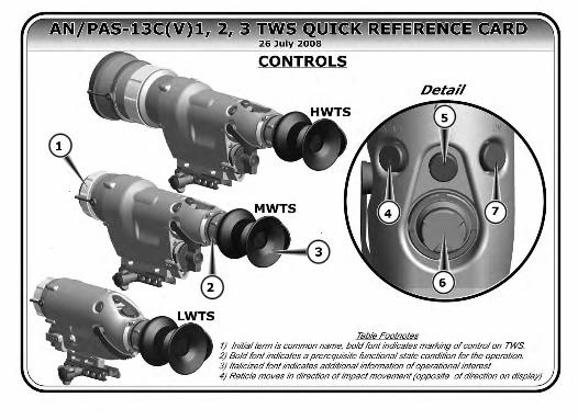
E-8
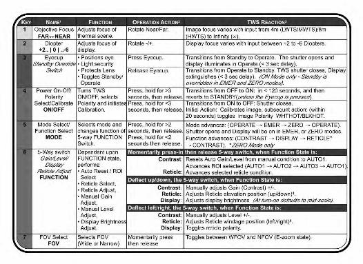
E-3
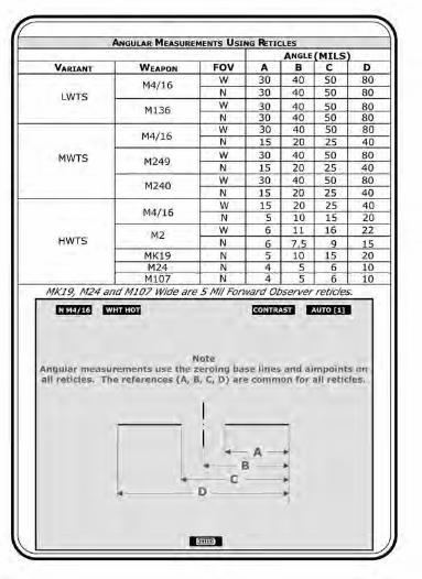
E-8
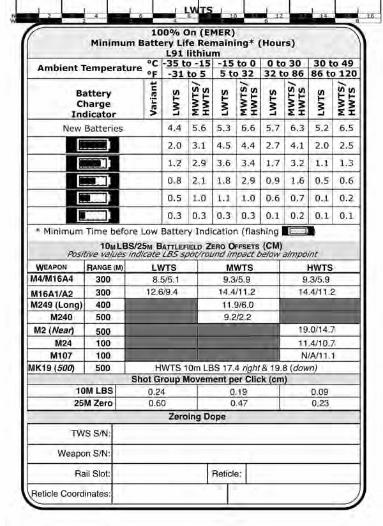
E-5
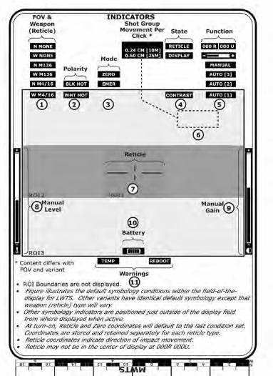
E-8

E-7

E-8
DISTRIBUTION: To be distributed in accordance with the initial distribution number (IDN) 362366 requirements for TM 11-5855-316-10.
By Order of the Secretary of the Army:
GEORGE W. CASEY, JRGeneral, United States Army
Chief of Staff
Official:
1022301
JOYCE E. MORROW Administrative Assistant to the
Secretary of the Army
TM 11-5855-316-10

E-8
This information is furnished upon the condition that it will not be released to another nation without the specific authority of the Department of the Army of the United States, that it will be used for military purposes only, that individual or corporate rights originating in the information, whether patented or not, will be respected, that the recipient will report promptly to the United States, any known or suspected compromise, and that the information will be provided substantially the same degree of security afforded it by the Department of Defense of the United States. Also, regardless of any other markings on the document, it will not be downgraded or declassified without written approval of the original United States agency.

PIN: 083352-000
*TM 11-5855-316-10