tm 10-4320-315-24 technical manual unit, direct … · tm 10-4320-315-24 technical manual unit,...
TRANSCRIPT

TM 10-4320-315-24
TECHNICAL MANUALUNIT, DIRECT SUPPORT AND
GENERAL SUPPORTMAINTENANCE MANUAL
PUMPING ASSEMBLY, WATER600 GPM,
TRAILER MOUNTED(NSN 4320-01-314-8844)
INTRODUCTION1-3
UNITMAINTENANCEINSTRUCTIONS
2-1
DIRECT SUPPORTMAINTENANCEINSTRUCTIONS
3-1
GENERAL SUPPORTMAINTENANCEINSTRUCTIONS
4-1
REFERENCESA-1
MAINTENANCEALLOCATION
CHARTB-1
EXPENDABLE/DURABLESUPPLIES AND
MATERIALS LISTC-1
STANDARD TORQUEVALUE CHART
D-1
DISTRIBUTION STATEMENT A: Approved for public release; distribution is unlimited.
HEADQUARTERS, DEPARTMENT OF THE ARMY15 JANUARY 1993

TM 10-4320-315-24WARNING
FLAMMABLE MATERIAL
• DO NOT operate engine around open fuel. Fuel presents an extreme explosion and firehazard. Make sure fuel lines are securely connected and free of leaks. Avoid overfilling fueltank. Always use correct type of fuel.
• To prevent fire or explosion, keep open flame, sparks, and cigarettes away from fuel tank and
battery.
WARNING
SOLVENT
• Solvent may cause toxic fumes. To prevent personal injury, work only in a well-ventilatedarea. DO NOT breath fumes for a long time.
• Solvent is flammable. To prevent fire or explosion, DO NOT bring open flame or sparks near
solvent.
WARNING
OVERHEATED PUMP
DO NOT operate pump against a closed suction or discharge line. This can cause overheatingand explosion.
WARNING
HEARING DAMAGE
Hearing protection must be worn by personnel standing within 50 ft (15 m) of operating pumpwhen enclosure doors are opened.
WARNING
SKIN BURNS
To prevent skin burns, do not touch hot engine or engine parts. Allow engine to cool beforedoing maintenance.
WARNING
To prevent injury during operation or maintenance, ensure jacks and tripod are in the downposition and wheels chocked.
FOR FIRST AID, SEE FM 21-11.
a/(b blank)
TM 10-4320-315-24
TECHNICAL MANUAL HEADQUARTERSDEPARTMENTS OF THE ARMY
NO. 10-4320-315-24 WASHINGTON, D.C., 15 JANUARY 1993
TECHNICAL MANUAL
Unit, Direct Support and General SupportMaintenance Manual
Pumping Assembly, Water600 GPM,
Trailer Mounted(NSN 4320-01-314-88443)
REPORTING ERRORS AND RECOMMENDING IMPROVEMENTS
You can help improve this manual. If you find any mistakes or if you know of a way to improve theprocedures, please let us know. Mail your letter or DA Form 2028 (Recommended Changes toPublications and Blank Forms), or DA Form 2028-2 located in the back of this manual directly to:Commander, US Army Aviation and Troop Command, ATTN: AMSAT-I-MTS, 4300 Goodfellow Blvd.,St. Louis, MO 63120-1798. A reply will be furnished directly to you.
DISTRIBUTION STATEMENT A: Approved for public release; distribution is unlimited.
TABLE OF CONTENTS
PAGE
WARNING PAGE ...................................................................................................... a
HOW TO USE THIS MANUAL .................................................................................. iii
CHAPTER 1 INTRODUCTION ...................................................................................................... 1-3
Section I General Information .................................................................................................. 1-3
Section II Equipment Description .............................................................................................. 1-5
Section III Technical Principles of Operation .............................................................................. 1-7
CHAPTER 2 UNIT MAINTENANCE .............................................................................................. 2-1
Section I Repair Parts, Special Tools, TMDE and Support Equipment ..................................... 2-1
Section II Service Upon Receipt ............................................................................................... 2-1
Section III Preparation for Storage and Shipment ...................................................................... 2-2
Section IV Preventive Maintenance Checks and Services (PMCS) ............................................ 2-4
Section V Unit Troubleshooting ................................................................................................. 2-6
Section VI Unit Maintenance Procedures ................................................................................... 2-20
CHAPTER 3 DIRECT SUPPORT MAINTENANCE ....................................................................... 3-1
Section I Repair Parts, Special Tools, TMDE and Support Equipment ..................................... 3-1
Section II Direct Support Troubleshooting ................................................................................. 3-1
i
TM 10-4320-315-24
TABLE OF CONTENTS (Continued)
PAGE
Section III Direct Support Maintenance Procedures ................................................................... 3-6
CHAPTER 4 GENERAL SUPPORT MAINTENANCE ................................................................... 4-1
Section I Repair Parts, Special Tools, TMDE and Support Equipment ..................................... 4-1
Section II General Support Maintenance Procedures ................................................................ 4-1
APPENDIX A REFERENCES .......................................................................................................... A-1
APPENDIX B MAINTENANCE ALLOCATION CHART .................................................................. B-1
APPENDIX C EXPENDABLE/DURABLE SUPPLIES AND MATERIALS LIST................................ C-1
APPENDIX D STANDARD TORQUE VALUE CHART ................................................................... D-1
GLOSSARY .................................................................................................................................. Glossary-1
ALPHABETICAL INDEX............................................................................................................................ Index-1
ii

TM 10-4320-315-24
HOW TO USE THIS MANUAL
The manual has been divided into chapters, sections, and paragraphs which are all numbered sequentially; figures andtables have also been numbered in the same manner. The manual identifies major components and their location whichwill aid you, the maintainer, in performing your PMCS. Detailed lubrication instructions, which are mandatory, are alsoincluded within the operator's maintenance section.
Use the front cover locators and "marked/tabbed" pages to quickly find the parts of the manual shown on the cover. The"blocked" titles in the table of contents are the titles for these locators. These portions of the manual were chosenbecause they are used most often.
Maintenance procedures used by Unit, Direct Support and General Support personnel are described on a step by stepmanner, ensuring the correct, and safe removal or repair of equipment. An alphabetical index at the back of the manualis referenced to the appropriate paragraph in the manual for ease of locating a specific task or procedure.
iii/(iv blank)

TM 10-4320-315-24
Figure 1-1. Full External View of Pumping Assembly, Water, 600 GPM, Trailer Mounted
1-1/(1-2 blank)

TM 10-4320-315-24
CHAPTER 1INTRODUCTION
PARAGRAPH TITLE PARAGRAPH
Destruction of Army Materiel to Prevent Enemy Use ................................................................................................. 1-3Equipment Data ...................................................................................................................................................... 1-11Equipment Characteristics, Capabilities, and Features .............................................................................................. 1-9Functional Description of Pumping Assembly .......................................................................................................... 1-12Location and Description of Major Components ....................................................................................................... 1-10Maintenance Forms, Records, and Reports ............................................................................................................... 1-2Nomenclature Cross-Reference List .......................................................................................................................... 1-8Preparation for Storage or Shipment ......................................................................................................................... 1-4Principles of Operation ............................................................................................................................................ 1-13Quality Assurance/Quality Control (QA/QC) .............................................................................................................. 1-5Reporting Equipment Improvement Recommendations (EIRs) .................................................................................. 1-6Safety, Care, and Handling ....................................................................................................................................... 1-7Scope ....................................................................................................................................................................... 1-1
Section I. GENERAL INFORMATION
1-1. Scope.
a. Type of Manual. Unit, Direct Support, and General Support Maintenance Manual.b. Model Number and Equipment Name. Pumping Assembly, Water, 600 GPM, Model No. 6 X 6 SP6, NSN 4320-
01-314-8844 (hereafter called pumping assembly).c. Purpose of Equipment. The pumping assembly is a component of water distribution systems. It is used either
singularly or in series with other pumps to supply drinking water from a source to one or more distribution points.
1-2. Maintenance Forms, Records, and Reports. Department of the Army forms and procedures used for equipmentmaintenance will be those prescribed by DA Pam 738-750, The Army Maintenance Management System (TAMMS).
1-3. Destruction of Army Materiel to Prevent Enemy Use. Command decisions, according to tactical situation, willdetermine when destruction of the pumping assembly will be accomplished. A destruction plan will be prepared by theusing organization, unless one has been prepared by higher authority. For general destruction procedures for thisequipment, refer to TM 750244-3, Procedures for Destruction of Equipment to Prevent Enemy Use.
1-4. Preparation for Storage or Shipment. Refer to Sections IV and V of Chapter 2 for requirements concerning thesepreparations.
1-5. Quality Assurance/Quality Control (QA/QC). The quality of the pumping assembly must at all times be incompliance with the requirements set forth by AMCPM-PWL. If a discrepancy is found to exist, notify your supervisor.
1-6. Reporting Equipment Improvement Recommendations (EIRs). If your Pumping assembly needs improvement,let us know. Send us an EIR. You, the user, are the only one who can tell us what you don't like about your equipment.Let us know why you don't like the design or performance. Put it on an SF 368 (Product Quality Deficiency Report). Mailit to us at Commander, U.S. Army Troop Support Command, ATTN: AMSAT-I-MDO 4300 Goodfellow Boulevard, St.Louis, Missouri 63120-1798. We'll send you a reply.
1-3

TM 10-4320-315-24
1-7. Safety, Care, and Handling. Safe and efficient pumping assembly operations depend on the observance of wellestablished safety practices and a thorough knowledge of operating procedures. The operating procedures often involveusing equipment and materials that are potentially hazardous. Injury to personnel and damage to equipment caused byfire, and misuse of equipment can be avoided by alert and responsible operators and technicians. Strict observance toestablished safety, care, and handling practices and procedures will allow personnel to perform their duties in a safe andhazard-free environment.
a. General Precautions. The following are general safety precautions that need to be observed by all operators ofthe pumping assembly.
Always be mindful of operations in progress. Never allow horseplay or loud talking that would divert the attentionof operators or technicians. If the pumping assembly is left unattended, be sure no safety hazard will resultbecause of absence.
Whenever in doubt concerning this operation, consult qualified authority for advice.
Do not attempt unauthorized shortcuts to save time, as they generally are not in accordance with safeprocedures.Be prepared for any emergencies which may arise, and be familiar with the proper action to take in event ofemergencies.
When ending daily operations, make a thorough and orderly check of equipment to be sure that no hazards maydevelop during the time that pumping assembly is unattended.
b. Preventing Fire. The following fire prevention rules must be observed:
Do not smoke in the vicinity of the engine or fuel tank.
Never us open flames in the vicinity of the engine or fuel tank.
Clean up liquid spills immediately.
Always pour acid into water; never pour water into acid.
Store oily rags in metal, airtight container.
c. Extinguishing Fires. Do not use water for extinguishing oil fires because it will spread the fire. Water is aconductor of electricity and should not be used on electrical fires.
d. Electrical Safety. The following electrical safety precautions apply to all operators and maintenance personnelfor the pumping assembly.
Equipment producing a tingle sensation will be reported promptly for repair.
Be sure insulation and wire size are adequate for the voltage and current to be carried.
Work on electrical devices should be done after the power has been disconnected or shut off, and suitableprecautions taken to keep the power off during the work.
Never use metallic pencils or rulers, or wear rings or watches when working on electrical equipment.
Avoid using or storing flammable liquids near electrical equipment.1-4

TM 10-4320-315-24
1-8. Nomenclature Cross-Reference List. This listing includes nomenclature cross-references used in this manual.
Common Name Official Nomenclature
Pumping Assembly Pumping Assembly, Water600 GPM, Trailer Mounted
Section II. EQUIPMENT DESCRIPTION
1-9. Equipment Characteristics, Capabilities, and Features.
a. Characteristics. The pumping assembly consists of a diesel-engine driven, self-priming centrifugal pump, controlpanel, and a noise enclosure mounted on a wheel-mounted trailer assembly.
b. Capabilities and Features. The pumping assembly has an operational output of 600 gpm at 150 psig whenpumping water.
(1) Self-priming pump.
(2) Air-cooled, diesel engine driven.
(3) Wheel-mounted trailer unit.
(4) Highly mobile.
(5) Sound attenuated to 70 db2.
1-10. Location and Description of Major Components (Figure 1-2).
a. PUMP ASSEMBLY (1). Rated at 600 gpm. Draws water from source or upline boost pump and feeds reservoiror next downline boost pump. Fitted with suction and discharge elbows suitable for connection to 6 in. groovedpipe couplings.
b. NOISE ENCLOSURE (2). Provides for noise reduction.
c. DIESEL ENGINE (3). Engine is a 4-stroke, 6 cylinder, air cooled diesel engine that drives pump. Operatingmode of engine is set on control panel. Operated in manual or automatic mode.
d. CONTROL PANEL (4). Controls system operations.
e. JACKS (5). Used to support and level pumping assembly.
f. TWO-WHEEL TRAILER ASSEMBLY (6). Transports pumping assembly.
g. TRIPOD ASSEMBLY (7). Supports front of pumping station in deployment mode. Tripod assembly is raised intravel mode.
h. PARKING BRAKES (8). Used to lock wheels in place when trailer is not in transit.
i. SURGE BRAKING SYSTEM (9). Provides braking for the pumping assembly when being towed. Activated bystopping motion of vehicle.
j. RUNNING/BRAKE LIGHTS (10). Provide visual traffic signals for in-transit use.
1-5

TM 10-4320-315-24
Figure 1-2. Location of Major Components
1-6
TM 10-4320-315-24
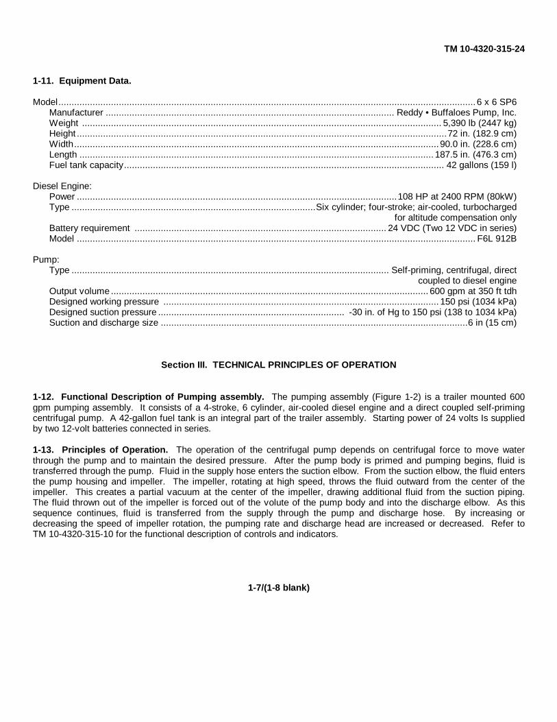
1-11. Equipment Data.
Model...............................................................................................................................................................6 x 6 SP6Manufacturer .............................................................................................................. Reddy • Buffaloes Pump, Inc.Weight ......................................................................................................................................... 5,390 lb (2447 kg)Height .............................................................................................................................................72 in. (182.9 cm)Width...........................................................................................................................................90.0 in. (228.6 cm)Length ....................................................................................................................................... 187.5 in. (476.3 cm)Fuel tank capacity.......................................................................................................................... 42 gallons (159 l)
Diesel Engine:Power ..........................................................................................................................108 HP at 2400 RPM (80kW)Type .............................................................................................Six cylinder; four-stroke; air-cooled, turbocharged
for altitude compensation onlyBattery requirement ................................................................................................ 24 VDC (Two 12 VDC in series)Model ........................................................................................................................................................ F6L 912B
Pump:Type ......................................................................................................................... Self-priming, centrifugal, direct
coupled to diesel engineOutput volume ......................................................................................................................... 600 gpm at 350 ft tdhDesigned working pressure ......................................................................................................... 150 psi (1034 kPa)Designed suction pressure ....................................................................... -30 in. of Hg to 150 psi (138 to 1034 kPa)Suction and discharge size .....................................................................................................................6 in (15 cm)
Section III. TECHNICAL PRINCIPLES OF OPERATION
1-12. Functional Description of Pumping assembly. The pumping assembly (Figure 1-2) is a trailer mounted 600gpm pumping assembly. It consists of a 4-stroke, 6 cylinder, air-cooled diesel engine and a direct coupled self-primingcentrifugal pump. A 42-gallon fuel tank is an integral part of the trailer assembly. Starting power of 24 volts Is suppliedby two 12-volt batteries connected in series.
1-13. Principles of Operation. The operation of the centrifugal pump depends on centrifugal force to move waterthrough the pump and to maintain the desired pressure. After the pump body is primed and pumping begins, fluid istransferred through the pump. Fluid in the supply hose enters the suction elbow. From the suction elbow, the fluid entersthe pump housing and impeller. The impeller, rotating at high speed, throws the fluid outward from the center of theimpeller. This creates a partial vacuum at the center of the impeller, drawing additional fluid from the suction piping.The fluid thrown out of the impeller is forced out of the volute of the pump body and into the discharge elbow. As thissequence continues, fluid is transferred from the supply through the pump and discharge hose. By increasing ordecreasing the speed of impeller rotation, the pumping rate and discharge head are increased or decreased. Refer toTM 10-4320-315-10 for the functional description of controls and indicators.
1-7/(1-8 blank)

TM 10-4320-315-24
CHAPTER 2UNIT MAINTENANCE INSTRUCTIONS
PARAGRAPH TITLE PARAGRAPH
Administrative Storage .............................................................................................................................................. 2-8Assembly and Preparation For Use ........................................................................................................................... 2-7Common Tools and Equipment ................................................................................................................................. 2-1General, Service Upon Receipt ................................................................................................................................. 2-4General, Unit Preventive Maintenance Checks and Services (PMCS) ..................................................................... 2-11Introduction, Unit Maintenance Procedures .............................................................................................................. 2-15PMCS Procedures ................................................................................................................................................... 2-13Preparation of Pumping Assembly for Shipment ..................................................................................................... 2-10Preparation of Pumping Assembly for Storage .......................................................................................................... 2-9Repair Parts .............................................................................................................................................................. 2-3Service Upon Receipt of Equipment........................................................................................................................... 2-6Site Requirements...................................................................................................................................................... 2-5Special Tools, TMDE and Support Equipment............................................................................................................ 2-2Unit Preventive Maintenance Checks and Services.................................................................................................. 2-12Unit Troubleshooting Procedures ............................................................................................................................ 2-14
Section I. REPAIR PARTS, SPECIAL TOOLS, TMDEAND SUPPORT EQUIPMENT
2-1. Common Tools and Equipment. Appendix B, Section III contains the authorized common tools. For authorizedequipment, refer to Modified Table of Organization and Equipment (MTOE) applicable to your unit.
2-2. Special Tools, TMDE and Support Equipment. No special tools, TMDE, or support equipment are required forthe repair of the pumping assembly at the unit level of maintenance.
2-3. Repair Parts. Repair parts for the pumping assembly are listed and illustrated in the Repair Parts and SpecialTools List (RPSTL) TM 10-4320-315-24P.
Section II. SERVICE UPON RECEIPT
2-4. General. When new, used or reconditioned equipment is first received, it is the responsibility of the person incharge to determine whether the equipment has been properly prepared for service by the supplying organization and tobe sure it is in condition to perform its function. For this purpose, inspect all assemblies, subassemblies, and accessoriesto be sure they are properly assembled, secure, clean and correctly adjusted and/or lubricated. Check all tools andequipment to be sure every item is present, in good condition, clean and properly mounted or stowed.
2-5. Site Requirements. Select a site that provides ample space to maneuver vehicles that may be used to move andposition a pumping assembly. Refer to applicable system manual.
2-6. Service Upon Receipt of Equipment.
a. Visually inspect the pumping assembly exterior starting at the rear to cover rear, sides, front, top, and bottom.Inspect for loose, missing, or damaged items. Check for signs of corrosion.
b. Open both sides of noise enclosure panels and inspect interior for loose, missing or damaged items. Check forwater damage, fungi, mildew, and corrosion.
2-1

TM 10-4320-315-24
c. Inventory items on or in the pumping assembly against the Components of End Item and Basic Issue Items Lists(TM 10-4320-315-10).
d. Report damage or discrepancies in accordance with DA PAM 738-750 for Quality Deficiency Report (SF-368).
2-7. Assembly and Preparation For Use.
a. Install and connect batteries (para. 2-16).
b. Fill engine crankcase with oil (Item 10, Appendix C). Refer to LO 10-4320-315-12.
WARNING
To avoid sparking between filler nozzle and fuel tank, always maintain metal to metal contactbetween filler nozzle and fuel tank when filling fuel tank.
Do not smoke or use open flame in vicinity of the generator set while fueling. Fire or explosionwill cause damage to equipment or could result in injury or death to personnel.
c. Fill fuel tank with clean fuel (Item 9, Appendix C).
d. Connect suction and discharge piping. Refer to applicable system TM.
Section III. PREPARATION FOR STORAGE AND SHIPMENT
2-8. Administrative Storage. This paragraph contains information on administrative storage procedures. If additionalinformation is required, refer to AR 750-1.
a. Storage Length and Readiness. Placement of equipment in administrative storage should be for short periods oftime (1 - 45 days) when a storage of maintenance efforts exists. Items should be in mission readiness within 24hours or within the time factors as determined by the directing authority. During the storage period, appropriatemaintenance records will be kept.
b. Prior to Placing Unit In Storage. Before placing equipment in administrative storage, current maintenanceservices and Preventive Maintenance Checks and Services (PMCS) should be completed, shortcomings anddeficiencies should be corrected, and all Modification Work Orders (MWOs) should be applied.
c. Storage Site Selection. Inside storage Is preferred for items selected for administrative storage. If inside storageis not available, the sites selected should provide required protection from the elements and allow access forvisual inspection when applicable.
2-9. Preparation of Pumping Assembly for Storage. The following steps describe procedures for storing the pumpingassembly.
NOTE
Always keep batteries completely charged during storage.
2-2

TM 10-4320-315-24
a. Short-Term Storage (less than 90 days). Perform the following steps:
(1) Clean and service batteries.
(a) Clean any corrosion from battery terminals and coat with a light film of non-conductive grease (Item8, Appendix C) to prevent corrosion buildup during storage.
(b) Check electrolyte level and fill to split ring, where necessary, with distilled water (Item 23, AppendixC).
(c) Check specific gravity with a battery electrolyte solution tester. Reading should be 1.260. Rechargeif necessary.
(2) Be sure fuel level in tank is full.
(3) Be sure oil level in engine is full.
(4) Lubricate (LO 10-4320-315-12).
b. Long-Term Storage (more than 90 days). Perform the following steps:
(1) Perform procedures listed in short-term storage (para. 2-9a).
(2) Service engine air intake.
(a) Remove air filter element (TM 10-4320-315-10).
(b) Start engine briefly, then shut off. As engine decelerates, spray 30 weight oil (Item 10, Appendix C)liberally into air intake.
(c) Replace air filter element CTM 10-4320-315-10).
c. Long-Term Cold Storage. At temperature below 32°F (0°C), the batteries must be kept at full charge (1.260specific gravity) to prevent freezing. Inspect and test every seven days and recharge as necessary.
2-10 Preparation of Pumping Assembly for Shipment. The pumping assembly is in a shippable form once it hasbeen shut down and stowed in accordance with the operating instructions. The pumping assembly is provided with D-rings on the trailer chassis for lifting with a four-legged sling. The D-rings are also used to secure the pumping assemblyto the decks of trucks, ships, or aircraft. The rear of the pumping assembly is fitted with forklift slots. Perform thefollowing checks prior to transporting:
a. Service engine air intake.
(1) Remove air filter element (TM 10-4320-315-10).
(2) Start engine briefly, then shut off. As engine decelerates, spray 30 weight oil (Item 10, Appendix C)liberally into air intake.
(3) Replace air filter element (TM 10-4320-315-10).
b. Check that all leveling and tripod jacks are locked in the transport position.
c. Close and secure noise enclosure doors.
2-3

TM 10-4320-315-24
Section IV. UNIT PREVENTIVE MAINTENANCE CHECKS AND SERVICES (PMCS)
2-11. General. To ensure that the pumping assembly is ready for operation at all times, it must be inspectedwithin designated intervals so that defects may be discovered and corrected before they result in serious damageor failure. Table 4-1 contains a tabulated listing of Preventive Maintenance Checks and Services to be performedby unit maintenance personnel. All deficiencies and shortcomings will be recorded as well as the corrective actiontaken on DA Form 2404 at the earliest possible opportunity.
2-12. Unit Preventive Maintenance Checks and Services.
a. The item numbers of Table 2-1 indicate the sequence of the PMCS. Perform at the intervals shown below:
(1) Do your (M) PREVENTIVE MAINTENANCE once each month.
(2) Do your (S) PREVENTIVE MAINTENANCE once each 6 months.
(3) Do your (H) PREVENTIVE MAINTENANCE at the hour interval listed.
(4) Do your (A) PREVENTIVE MAINTENANCE once each year.
b. Refer to TM 104320-315-10, operator PMCS, for leakage definitions.
2-13. PMCS Procedures. The following paragraphs describe your PMCS table.
a. Item Number Column. This number shall be used as a source of item numbers for the "TM number" column onDA Form 2404, Equipment Inspection and Maintenance Worksheet, in recording results of PMCS.
b. Interval Columns. A dot shall be placed in the appropriate column marked "M" for monthly, "S" for semiannual,"A" for annual, and "H" for operating hours.
c. Item to be Inspected. Items listed in this column are divided by group indicating the part of the equipment eachbelongs to, i.e., engine", "battery", "frame assy".
d. Procedures Column. This column contains a brief description of the check to be performed.
e. Equipment Is Not Ready/Available If Column. This column is used for identification of conditions that make theequipment not ready/available for readiness reporting purposes or denies use of the equipment until correctivemaintenance is performed.
f. Reporting and Correcting Deficiencies. If your equipment does not perform as required, refer to Section V underTroubleshooting for possible problems. Report any malfunctions or failures on the proper DA Form 2404, or referto DA Pam 738-750.
g. Leakage. Leakage definitions shall be classified as follows:
Class I Seepage of fluid, as indicated by wetness or discoloration not great enough to form drops.
Class II Leakage of fluid great enough to form drops but not enough to cause drops to drip from item beingchecked/inspected.
Class III Leakage of fluid great enough to form drops that fall from the item being checked/inspected.
2-4

TM 10-4320-315-24Table 2-1. Unit Preventive Maintenance Checks and Services Procedures
Interval Item Procedures Equipment isItem to be Check for and have repaired Not Read/No. M S A H Inspected or adjusted as necessary Available If:
1 • Batteries Check specific gravity (TM 9-6140-200-14). Specific gravityReplace or recharge as required. of cells is less
than 1.260.2 • Engine Check for cracks or leaks. Tighten loose Loose
mounting hardware. If engine is damaged or hardware.leaking, notify supervisor. Leaks and/or
cracks arefound.
3 • Engine Check every 125 hours for accumulation ofCooling dust on inside of cooling air blower andSystem cylinder cooling fins. Remove and clean any
accumulation.4 • Engine Oil Change oil every 250 hours (LO 10-4320-
315-12). Change oil at 50 hours for new oroverhauled engines.
5 • V-Belts Inspect for wear and tension every 250 Worn V-belts.hours. Replace and adjust if necessary Deflection(para. 2-41). exceeds 1/2 in.
(12.7 mm).6 • Engine Check valve clearance every 500 hours.
Valve Adjust if required (para. 2-55).Clearance
7 • Fuel Filters Change fuel filters every 1000 hours (para.2-43).
8 • Fuel Supply Check and clean strainer every 1000 hoursPump (para. 2-51).Strainer
9 • Brake Lines Check brake lines for leaks. Replace leaky Class III leak.lines (para. 2-57).
10 • Brake Shoes Check brake shoes for wear. Replace if Worn brakeworn to rivets (para. 2-59). shoes.
11 • Pump and Check for cracks and leaks. Check for loose HardwareElbow or missing mounting hardware. Tighten missing and/or
loose mounting hardware. Replace missing leaks occurmounting hardware.
12 • Exhaust Inspect muffler and pipes for damage and Damaged orPipes and leaks. leaky mufflerMuffler and pipes.
13 • Wheel Clean, inspect, and repack wheel bearings Annually orBearing (para. 2-58). 3000 hours
whichevercomes first
2-5

TM 10-4320-315-24
Section V. UNIT TROUBLESHOOTING PROCEDURES
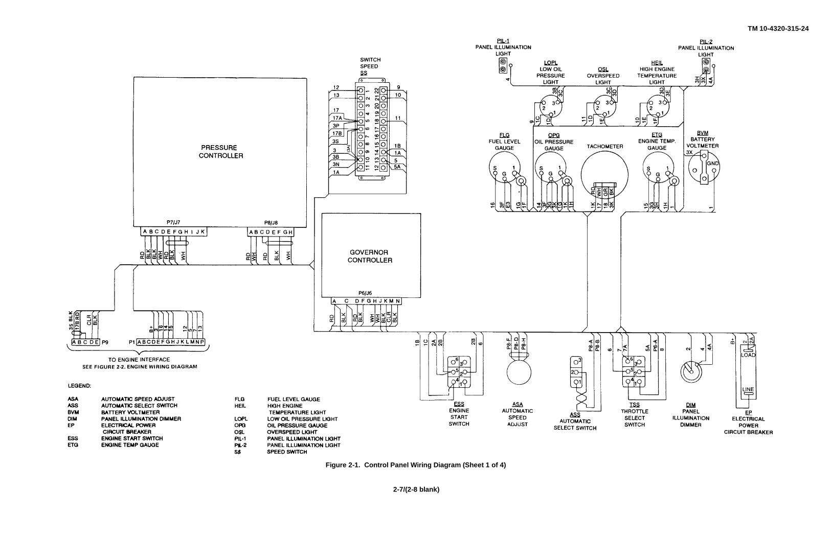
2-14 Unit Troubleshooting Procedures. Unit troubleshooting procedures listed in Table 2-2 cover the mostcommon malfunctions that may be repaired at the unit level. Repair or adjustment requiring specialized equipmentis not authorized unless such equipment is available. Troubleshooting procedures used by the operator should beconducted in addition to the unit troubleshooting procedures. Refer to TM 10-4320-315-10. This manual cannotlist all the possible malfunctions or every possible test/inspection and corrective action. If a malfunction is not listedor corrected by a listed corrective action, notify your supervisor. Figures 2-1 and 2-2 are provided to aid introubleshooting the power distribution circuits.
SYMPTOM
TroubleshootingProcedure
(Para)Engine Does Not Crank........................................................................................................................................1Engine Cranks, But Does Not Start or Is Hard to Start .........................................................................................2Engine Stops Suddenly .......................................................................................................................................3Engine Smokes....................................................................................................................................................4Improper Governor System Operation .................................................................................................................5Engine Overheating .............................................................................................................................................6
2-6
TM 10-4320-315-24
Figure 2-1. Control Panel Wiring Diagram (Sheet 1 of 4)
2-7/(2-8 blank)

TM 10-4320-315-24
Figure 2-1. Control Panel Wiring Diagram (Sheet 2 of 4)
2-9/(2-10 blank)

TM 10-4320-315-24
Figure 2-2. Engine Wiring Diagram (Sheet 1 of 2)
2-13/(2-14 blank)
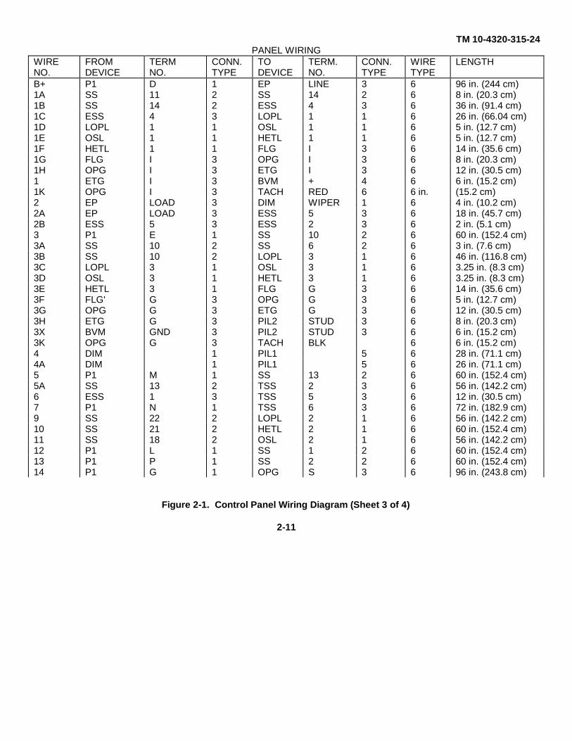
TM 10-4320-315-24PANEL WIRING
WIRE FROM TERM CONN. TO TERM. CONN. WIRE LENGTHNO. DEVICE NO. TYPE DEVICE NO. TYPE TYPEB+ P1 D 1 EP LINE 3 6 96 in. (244 cm)1A SS 11 2 SS 14 2 6 8 in. (20.3 cm)1B SS 14 2 ESS 4 3 6 36 in. (91.4 cm)1C ESS 4 3 LOPL 1 1 6 26 in. (66.04 cm)1D LOPL 1 1 OSL 1 1 6 5 in. (12.7 cm)1E OSL 1 1 HETL 1 1 6 5 in. (12.7 cm)1F HETL 1 1 FLG I 3 6 14 in. (35.6 cm)1G FLG I 3 OPG I 3 6 8 in. (20.3 cm)1H OPG I 3 ETG I 3 6 12 in. (30.5 cm)1 ETG I 3 BVM + 4 6 6 in. (15.2 cm)1K OPG I 3 TACH RED 6 6 in. (15.2 cm)2 EP LOAD 3 DIM WIPER 1 6 4 in. (10.2 cm)2A EP LOAD 3 ESS 5 3 6 18 in. (45.7 cm)2B ESS 5 3 ESS 2 3 6 2 in. (5.1 cm)3 P1 E 1 SS 10 2 6 60 in. (152.4 cm)3A SS 10 2 SS 6 2 6 3 in. (7.6 cm)3B SS 10 2 LOPL 3 1 6 46 in. (116.8 cm)3C LOPL 3 1 OSL 3 1 6 3.25 in. (8.3 cm)3D OSL 3 1 HETL 3 1 6 3.25 in. (8.3 cm)3E HETL 3 1 FLG G 3 6 14 in. (35.6 cm)3F FLG' G 3 OPG G 3 6 5 in. (12.7 cm)3G OPG G 3 ETG G 3 6 12 in. (30.5 cm)3H ETG G 3 PIL2 STUD 3 6 8 in. (20.3 cm)3X BVM GND 3 PIL2 STUD 3 6 6 in. (15.2 cm)3K OPG G 3 TACH BLK 6 6 in. (15.2 cm)4 DIM 1 PIL1 5 6 28 in. (71.1 cm)4A DIM 1 PIL1 5 6 26 in. (71.1 cm)5 P1 M 1 SS 13 2 6 60 in. (152.4 cm)5A SS 13 2 TSS 2 3 6 56 in. (142.2 cm)6 ESS 1 3 TSS 5 3 6 12 in. (30.5 cm)7 P1 N 1 TSS 6 3 6 72 in. (182.9 cm)9 SS 22 2 LOPL 2 1 6 56 in. (142.2 cm)10 SS 21 2 HETL 2 1 6 60 in. (152.4 cm)11 SS 18 2 OSL 2 1 6 56 in. (142.2 cm)12 P1 L 1 SS 1 2 6 60 in. (152.4 cm)13 P1 P 1 SS 2 2 6 60 in. (152.4 cm)14 P1 G 1 OPG S 3 6 96 in. (243.8 cm)
Figure 2-1. Control Panel Wiring Diagram (Sheet 3 of 4)
2-11
TM 10-4320-315-24
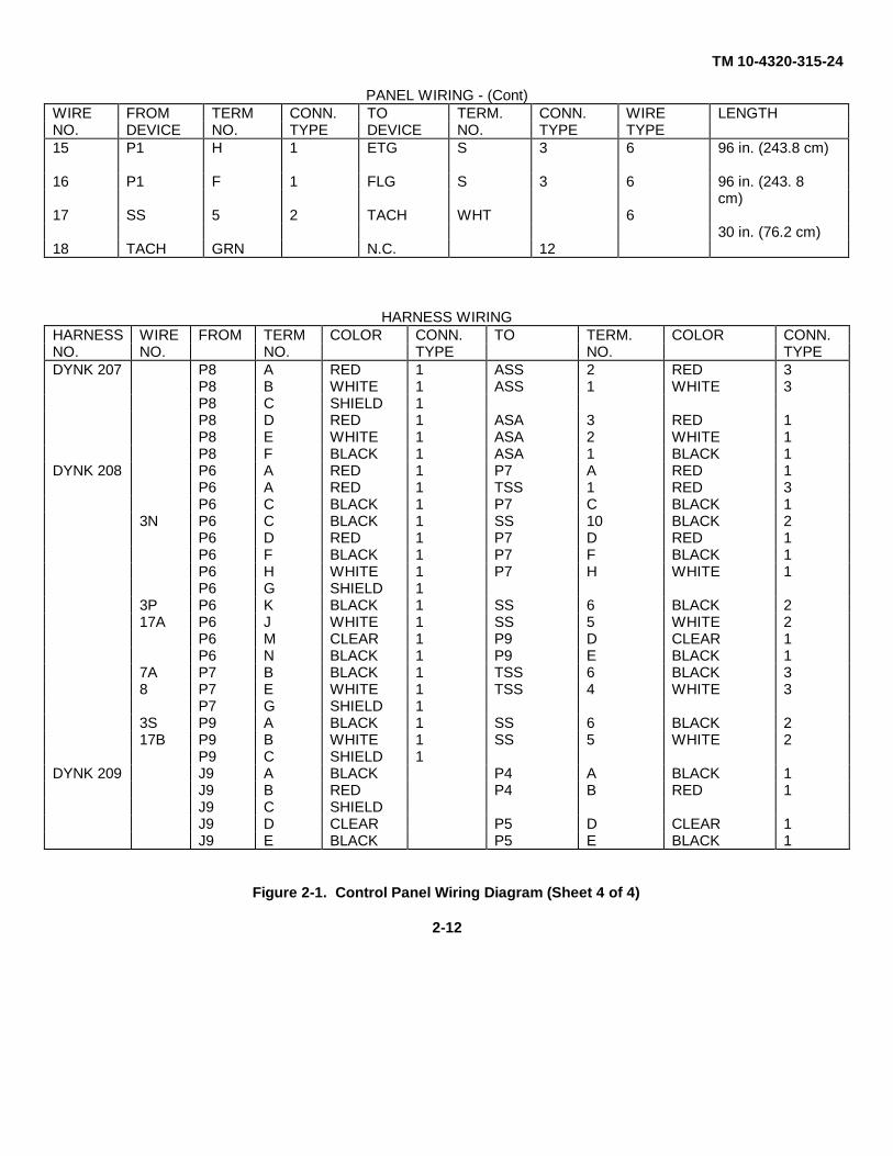
PANEL WIRING - (Cont)WIRE FROM TERM CONN. TO TERM. CONN. WIRE LENGTHNO. DEVICE NO. TYPE DEVICE NO. TYPE TYPE15 P1 H 1 ETG S 3 6 96 in. (243.8 cm)
16 P1 F 1 FLG S 3 6 96 in. (243. 8cm)
17 SS 5 2 TACH WHT 630 in. (76.2 cm)
18 TACH GRN N.C. 12
HARNESS WIRINGHARNESS WIRE FROM TERM COLOR CONN. TO TERM. COLOR CONN.NO. NO. NO. TYPE NO. TYPEDYNK 207 P8 A RED 1 ASS 2 RED 3
P8 B WHITE 1 ASS 1 WHITE 3P8 C SHIELD 1P8 D RED 1 ASA 3 RED 1P8 E WHITE 1 ASA 2 WHITE 1P8 F BLACK 1 ASA 1 BLACK 1
DYNK 208 P6 A RED 1 P7 A RED 1P6 A RED 1 TSS 1 RED 3P6 C BLACK 1 P7 C BLACK 1
3N P6 C BLACK 1 SS 10 BLACK 2P6 D RED 1 P7 D RED 1P6 F BLACK 1 P7 F BLACK 1P6 H WHITE 1 P7 H WHITE 1P6 G SHIELD 1
3P P6 K BLACK 1 SS 6 BLACK 217A P6 J WHITE 1 SS 5 WHITE 2
P6 M CLEAR 1 P9 D CLEAR 1P6 N BLACK 1 P9 E BLACK 1
7A P7 B BLACK 1 TSS 6 BLACK 38 P7 E WHITE 1 TSS 4 WHITE 3
P7 G SHIELD 13S P9 A BLACK 1 SS 6 BLACK 217B P9 B WHITE 1 SS 5 WHITE 2
P9 C SHIELD 1DYNK 209 J9 A BLACK P4 A BLACK 1
J9 B RED P4 B RED 1J9 C SHIELDJ9 D CLEAR P5 D CLEAR 1J9 E BLACK P5 E BLACK 1
Figure 2-1. Control Panel Wiring Diagram (Sheet 4 of 4)
2-12

TM 10-4320-315-24WIRE FROM TERM. CONN. TO TERM. CONN. WIRE LENGTHNO. DEVICE NO. TYPE DEVICE NO. TYPE TYPE18 J1 M 1 FUEL 7 6 60 in.
SOLENOID (152 cm)
18A FUEL 7 ALTERNATOR 1 6 120 in.SOLENOID RESISTOR (305 cm)
19 J1 L OIL PRESSURE 8 6 48 in.SWITCH (121.9 cm)
20 J1 P 1 ENGINE TEMP. 8 6 48 in.SWITCH (121.9 cm)
21 J1 G 1 OIL PRESSURE 3 6 48 in.SENDER (121.9 cm)
22 J1 H 1 OIL TEMP. 3 6 52 in.SWITCH (132.1 cm)
23 J1 F 1 FUEL LEVEL 3 6 60 in.SENDER (152.4 cm)
24 J1 N 1 AUX. START A 8 6 72 in.RELAY (182.9 cm)
25 J1 E 1 ENGINE 9 6 36 in.BLOCK GRD. (91.4 cm)
26 J1 D 1 ENGINE 9 10 80 in.STARTER (203.2 cm)SOLENOID
26A ENGINE 9 AUX. START 7 8 10 18 in.STARTER RELAY (45.7 cm)SOLENOID
27 AUX. 5 8 ENGINE 11 10 18 in.START STARTER (45.7 cm)RELAY SOLENOID COIL
G1 FUEL 7 ENGINE 9 6 36 in.SOLENOID BLOCK GRD. (91.4 cm)
Figure 2-2. Engine Wiring Diagram (Sheet 2 of 2)
2-15

TM 10-4320-315-24
Table 2-2. Troubleshooting Procedures
MALFUNCTIONTEST OR INSPECTION
CORRECTIVE ACTION
1. ENGINE DOES NOT CRANK.
NOTE
Refer to electrical schematics of control panel and engine wiring harness when making voltageand resistance checks.
Step 1. While attempting to crank engine observe voltmeter on control panel.
If no voltage is indicated, check for open in wiring and main power and start/run switches usingmultimeter. Replace/repair wiring harness or replace defective switch as required (para. 2-23 and 2-24).
If voltage is greater than 0 but less than 18 VDC, charge or replace battery (para. 2-16).
Step 2. If battery was charged/replaced in step 1 and engine is now running, recheck voltage.
If voltage of 24 VDC or above is indicated, continue with mission.
If voltage reading of less than 24 VDC is indicated, original fault may have been caused by faultyalternator, replace alternator (para. 2-52).
Step 3. Check for loose wire/cable connections on batteries, starter and starter relay, and check all groundconnections.
As required tighten cable/wire connections. If engine still does not crank, replace starter and notifydirect support maintenance.
Step 4. Hold start switch to start position and check for 24 VDC at starter power input terminal.
If 24 VDC is not measured, check batteries.
If 24 VDC is measured, check starter circuitry between:
a. Starter solenoid and 24 VDC slave receptacle.
b. Slave receptacle and batteries.
c. Pin N24 and starter solenoid.
If engine still does not start, notify direct support maintenance.
2. ENGINE CRANKS, BUT DOES NOT START OR IS HARD TO START.
Step 1. Using multimeter, check voltage across battery terminals.
If reading is less than 24 volts, service or replace batteries (para. 2-16).
2-16

TM 10-4320-315-24Table 2-2. Troubleshooting Procedures - (Cont)
MALFUNCTIONTEST OR INSPECTION
CORRECTIVE ACTION
2. ENGINE CRANKS, BUT DOES NOT START OR IS HARD TO START - (Cont)
Step 2. Check battery connections for tightness and cleanliness.
Tighten loose connections (para. 2-16). Clean dirty connections.
Step 3. Check to see if air filter element is clean.
Clean or replace air filter element (TM 10-4320-315-10).
Step 4. Check to see if fuel lines are damaged or leaking.
Replace damaged fuel lines (para. 2-38, 2-43, and 2-49).
Step 5. Check to see if drain plugs on primary fuel filters are leaking or missing.
Replace primary fuel filter (para. 2-43).
Step 6. Check to see if primary fuel filter is clean.
Replace filter (para. 2-43).
Step 7. Disconnect outlet line on fuel supply pump. Using manual pumping lever, check to see if enoughfuel is being pumped.
If enough fuel is being pumped, go to step 8. If not enough fuel is being pumped, check condition of fuel supply pump diaphragm (para 2-51).
Step 8. Using multimeter set to 200-ohm scale, check reading across fuel solenoid coil as follows:
Remove screw and remove plug from fuel solenoid.
Place multimeter leads on pins 1 and 2. If reading is not between 60 and 70 ohms, replace fuelsolenoid.
If malfunction still exists, notify direct support maintenance.
2-17

TM 10-4320-315-24Table 2-2. Troubleshooting Procedures - (Cont)
MALFUNCTIONTEST OR INSPECTION
CORRECTIVE ACTION
3. ENGINE STOPS SUDDENLY.
Step 1. Check engine warning lights.
If LOW OIL light is on go to step 3.
If HIGH temperature light is on go to step 5.
If overspeed light is on go to MALFUNCTION 5.
Step 2. Using multimeter set to 200-ohm scale, check reading across fuel solenoid coil as follows:
Remove screw and remove plug from fuel solenoid.
Place multimeter leads on pins 1 and 2. If reading is not between 60 and 70 ohms, replace fuel solenoid.
If solenoid is good, replace engine protection module (para. 2-28).
Step 3. Check dipstick for low oil in engine.
Add oil as necessary.
Step 4. Check oil pressure switch for open contacts.
Replace switch (para. 2-37) if open circuit is measured between switch terminal and case ground.
If switch is good, replace engine protection module (para. 2-28).
Step 5. If HIGH temperature light is on, go to malfunction 6.
Check for open temperature switch.
Replace temperature switch (para. 2-37) if switch is open between case ground and terminal.
Step 6. Remove cowling cover and check for dirt accumulation between fins of cylinders and in air passages.
If dirty, clean fins and passages.
If fins and passages are clean, replace engine protection module (para. 2-28).
If malfunction still exists, refer to direct support maintenance.
2-18

TM 10-4320-315-24
Table 2-2. Troubleshooting Procedures - (Cont)
MALFUNCTIONTEST OR INSPECTION
CORRECTIVE ACTION
4. ENGINE SMOKES.
Step 1. Check cylinder head valve adjustment.
Adjust valves (para. 2-55)
Step 2. Check fuel return lines for blockage.
Remove blockage. If malfunction still exists, refer to direct support maintenance.
56. IMPROPER GOVERNOR SYSTEM OPERATION.
NOTE
Refer to electrical wiring diagrams of control panel (Figure 2-1) and engine wiring harness(Figure 2-2) when making voltage and resistance checks.
Step 1. Check and see if actuator linkage is stuck, loose or out of adjustment.
As necessary, adjust actuator linkage.
Step 2. Check adjustment of MPU (para. 2-36).
As necessary, adjust MPU (para. 2-36).
Step 3. Using multimeter check for MPU signal at input cable of governor control module (pins K and J).
Replace MPU if signal is absent. Signal is a small AC voltage.
Step 4. Disconnect cable from governor control module and measure resistance between pins C and H oncable while turning AUTO THROTTLE rheostat through its full range.
Replace AUTO THROTTLE (ASA) if resistance is not variable throughout the full range of AUTO THROTTLE (ASA) (para. 2-25).
Step 5. Check THROTTLE SELECT (ASS) switch for open/shorted contacts.
Replace switch if defective (para. 2-24).
Step 6. Check AUTO SELECT PRESSURE/SPEED switch (TSS) selector for open/shorted contacts.
Replace switch if defective (para. 2-24).
2-19

TM 10-4320-315-24
Table 2-2. Troubleshooting Procedures - (Cont)
MALFUNCTIONTEST OR INSPECTION
CORRECTIVE ACTION
5. IMPROPER GOVERNOR SYSTEM OPERATION - (Cont)
Step 7. Check for governor actuator output signal between pins N and M of cable plug P1. With pumpingassembly operating, signal should be a positive DC voltage which changes in magnitude whenAUTO THROTTLE (ASA) is turned.
If signal is correct, replace governor actuator (para. 2-30).
If signal is not correct, change governor control module (para. 2-27) and if that doesn't work, change pressure control module (para 2-26).
6. ENGINE OVERHEATING.
Check V-belt tensioner assembly for proper tension.
Replace V-belt tensioner if damaged (para. 2-44).
Section VI. UNIT MAINTENANCE PROCEDURES
PARAGRAPH TITLE PARAGRAPH
Air Cleaner and Air Intake Line ................................................................................................................................... 2-39Air Filter Gage and Hose ............................................................................................................................................ 2-34Alternator ................................................................................................................................................................... 2-52Auto Defeat Cable....................................................................................................................................................... 2-31Auto Select, Throttle Select, and Engine Switches ..................................................................................................... 2-24Battery Assembly and Battery Box ............................................................................................................................. 2-16Brake Actuator ........................................................................................................................................................... 2-56Brake Shoes and Wheel Cylinders ............................................................................................................................. 2-59Cold Start Aid Hose, Bottle and Cable ........................................................................................................................ 2-33Control Panel Assembly ............................................................................................................................................. 2-17Control Panel Wire Harness ....................................................................................................................................... 2-29Cooling Blower Assembly ........................................................................................................................................... 2-42Cylinder Head Assembly ............................................................................................................................................ 2-55Cylinder Head Cover .................................................................................................................................................. 2-54Electrical Switch ......................................................................................................................................................... 2-23Engine High Temperature, Engine Overspeed, and Engine Low Oil Indicators ........................................................... 2-18Engine Oil Drain Line ................................................................................................................................................. 2-40Engine Protection System Module .............................................................................................................................. 2-28Engine Temperature, Oil Pressure, and Fuel Tank Gages .......................................................................................... 2-19Engine Temperature and Oil Pressure Switches and Senders .................................................................................... 2-37Engine Volts Meter ..................................................................................................................................................... 2-20Engine Wiring Harness ............................................................................................................................................... 2-35Fuel Filter Assembly .................................................................................................................................................. 2-43Fuel Injection Lines .................................................................................................................................................... 2-49Fuel Injectors ............................................................................................................................................................. 2-50Fuel Supply Pump ...................................................................................................................................................... 2-51Fuel Valves and Lines ................................................................................................................................................ 2-38
2-20

TM 10-4320-315-24
Governor Actuator Assembly ...................................................................................................................................... 2-30Governor Control Module ........................................................................................................................................... 2-27Hand Brake Assembly ................................................................................................................................................ 2-60Introduction ................................................................................................................................................................ 2-15Leveling Jacks and Tripod Jack Assembly ................................................................................................................. 2-62Lights and Auto Throttle Rheostats ............................................................................................................................. 2-25Lube Oil Filter Assembly ............................................................................................................................................ 2-46Magnetic Pickup Unit (MPU) ...................................................................................................................................... 2-36Manual Throttle Control Cable .................................................................................................................................... 2-32Master Cylinder and Brake Lines ................................................................................................................................ 2-57Oil Breather Assembly ............................................................................................................................................... 2-48Oil Cooler ................................................................................................................................................................... 2-47Pressure Control Module ............................................................................................................................................ 2-26Pump Pressure Gages ............................................................................................................................................... 2-22Reflectors ................................................................................................................................................................... 2-64Shock Absorbers ........................................................................................................................................................ 2-63Starter Assembly ........................................................................................................................................................ 2-53Tachometer and Run Time Meter ............................................................................................................................... 2-21Turbocharger Oil Inlet Tube Assembly ....................................................................................................................... 2-45V-Belts ........................................................................................................................................................................ 2-41V-Belt Tensioner Assembly ........................................................................................................................................ 2-44Wheel, Tire, and Hub Assembly ................................................................................................................................. 2-58Wiring Harness and Tail Lights ................................................................................................................................... 2-61
2-15. Introduction . This section contains instructions covering maintenance functions for the Unit Level maintenancepersonnel on the pumping assembly.
2-21

TM 10-4320-315-24
2-16. MAINTENANCE OF BATTERY ASSEMBLY AND BATTERY BOX
This task covers:a. Service b. Remove c. Install
INITIAL SETUP :
Tools General Safety Instructions
General Mechanics Tool Kit(Item 1, Appendix B) WARNING
Materials/Parts Do not smoke while servicing batteries. Explosivegases are emitted from batteries in operation.
Lockwashers (TM 10-4320-315-24P) Ignition of these gases can cause severe personalinjury.
ReferencesEquipment Conditions
TM 9-6140-200-14Pumping assembly is shutdown. (Refer to TM 10-4320-315-10)
a. SERVICE.
Refer to TM 9-6140-200-14.
b. REMOVE. (Figure 2-3)
(1) Remove batteries as follows:
(a) Disconnect negative battery cable (1) from battery terminal (2).
(b) Disconnect positive battery cable (3) from battery terminal (4).
(c) Disconnect battery cable (5) from battery terminals (6 and 7).
(d) Remove nuts (8), lockwashers (9), bolts (10), and battery bracket (11).
(e) Remove batteries (12 and 13) from battery box (14).
(2) Remove capscrews (15), lockwashers (16), and battery box (14). Discard lockwashers.
c. INSTALL.
(1) Install battery box (14) with lockwashers (16) and capscrews (15).(2) Install batteries as follows:
(a) Install batteries (12 and 13) in battery box (14).(b) Install battery bracket (11) with bolts (10), lockwashers (9), and nuts (8).(c) Connect battery cable (5) to battery terminals (6 and 7).
2-22

TM 10-4320-315-24
2-16. MAINTENANCE OF BATTERY ASSEMBLY AND BATTERY BOX - (Cont)
(d) Connect positive battery cable (3) to battery terminal (4).(e) Connect negative battery cable (1) to battery cable (2).
Figure 2-3. Battery Assembly
2-23

TM 10-4320-315-24
2-16. MAINTENANCE OF CONTROL PANEL ASSEMBLY
This task covers:a. Remove b. Install
INITIAL SETUP :
Tools Equipment Conditions
General Mechanics Tool Kit Battery assembly is disconnected (para. 2-16).(Item 1, Appendix B)
Personnel RequiredMaterials/Parts
TwoTags (Item 21, Appendix C)
a. REMOVE. (Figure 2-4)
(1) Open engine access door (1).
(2) Disconnect electrical connectors P1 and P9 from J1 and J9 on mounting bracket behind control panel.
(3) Open control panel door (2). Tag and disconnect flexible tube assemblies (3) at drain valves (4) and at
pump gage valves (5). Pull tube assemblies (3) through grommet (6) from rear of control panel (7).
(4) Remove nuts (8), lockwashers (9), flat washers (10), and bolts (11) holding control panel (7).
(5) Remove control panel (7).
b. INSTALL.
(1) Clean mounting surfaces.
(2) Position replacement control panel (2) on mounting holes and secure with bolts (11), flat washers (10),
lockwashers (9), and nuts (8).
(3) Feed flexible tube assemblies (3) through grommet (6) in control panel (2) and connect at drain valves (4)
and pump gage valves (5) as tagged. Remove tags.
(4) Connect electrical connectors P1 and P9 to J1 and J9 behind control panel.
(5) Close and lock control panel door (2) and engine access door (1).
2-24

TM 10-4320-315-24
2-17. MAINTENANCE OF CONTROL PANEL ASSEMBLY - (Cont)
Figure 2-4. Control Panel Assembly
2-25

TM 10-4320-315-24
2-16. MAINTENANCE OF ENGINE HIGH TEMPERATURE, ENGINE OVERSPEED, AND ENGINE LOW OIL INDICATORS
This task covers:a. Remove b. Install
INITIAL SETUP :
Tools Equipment Conditions
General Mechanics Tool Kit Pumping assembly is shutdown (refer to TM10-4320-(Item 1, Appendix B) 315-10).
Soldering Gun Battery assembly is disconnected (para. 2-16).(Item 2, Appendix B)
Materials/Parts
Solder (Item 18, Appendix C)Tags (Item 21, Appendix C)
NOTE
This replacement procedure is for the ENGINE OVERSPEED indicator. Replacement of theENGINE HIGH TEMPERATURE and ENGINE LOW OIL indicators are identical.
a. REMOVE. (Figure 2-5)
Figure 2-5. Engine High Temperature, Overspeed and Low 011 Indicators
2-26

TM 10-4320-315-24
2-18. MAINTENANCE OF ENGINE HIGH TEMPERATURE, ENGINE OVERSPEED, AND ENGINE LOW OILINDICATORS - (Cont)
(1) Open control panel door (1) to gain access to rear of indicator (4).
(2) Tag and unsolder electrical leads from indicator (4). See wiring diagram (Figure 2-1, Sheet 1).
(3) Unscrew bulb assembly (2).
(4) Remove outer nut (3) and indicator (4).
(5) Remove nut (5) from indicator (4).
b. INSTALL.
(1) As necessary, clean mounting surfaces on control panel door (1).
(2) Install bulb assembly (2) in cutout on panel door (1) with nuts (3 and 4).
(3) Reattach wires as tagged, using soldering iron.
(4) Close control panel door (1).
2-27

TM 10-4320-315-24
2-16. MAINTENANCE OF ENGINE TEMPERATURE, OIL PRESSURE, AND FUEL TANK GAGES
This task covers:a. Remove b. Install
INITIAL SETUP :
Tools Equipment Conditions
General Mechanics Tool Kit Pumping assembly is shutdown (refer to TM 10-4320-(Item 1, Appendix B) 315-10).
Battery assembly is disconnected (para. 2-16).Materials/Parts
Tags (Item 21, Appendix C)
a. REMOVE. (Figure 2-6)
NOTE
This replacement procedure is for the OIL PRESSURE gage. Replacement of the ENGINETEMPERATURE and FUEL TANK gages are identical.
Figure 2-6. Engine Temperature and Oil Gages
2-28

TM 10-4320-315-24
2-19. MAINTENANCE OF ENGINE TEMPERATURE, OIL PRESSURE, AND FUEL TANK GAGES - (Cont)
(1) Open control panel door (1).
(2) Tag and disconnect wires from gage (6), removing nuts (2) and flat washers (3). See wiring diagram
(Figure 2-1, Sheet 1).
(3) Remove nuts (4) and bracket (5).
(4) Remove gage (6) with star washer (7).
b. REPLACE.
(1) Position replacement gage (6) with star washers (7) in mounting hole on control panel door (1).
(2) Secure with bracket (5) and nuts (4).
(3) Connect wires as tagged. Secure with flat washers (3) and nuts (2).
(4) Close control panel (1).
2-29
TM 10-4320-315-24
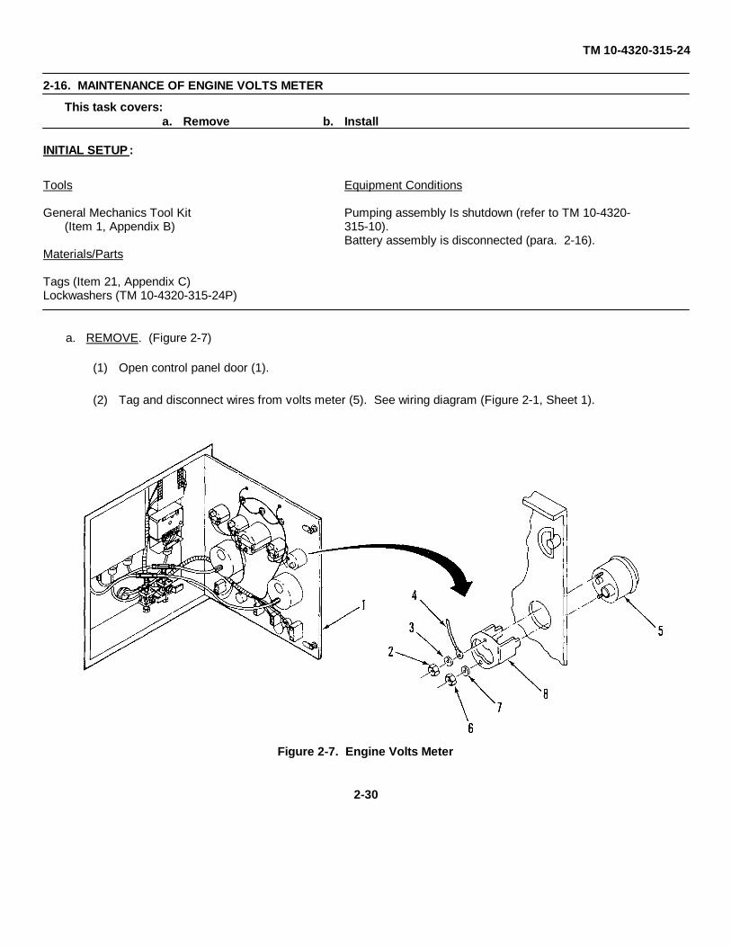
2-16. MAINTENANCE OF ENGINE VOLTS METER
This task covers:a. Remove b. Install
INITIAL SETUP :
Tools Equipment Conditions
General Mechanics Tool Kit Pumping assembly Is shutdown (refer to TM 10-4320-(Item 1, Appendix B) 315-10).
Battery assembly is disconnected (para. 2-16).Materials/Parts
Tags (Item 21, Appendix C)Lockwashers (TM 10-4320-315-24P)
a. REMOVE. (Figure 2-7)
(1) Open control panel door (1).
(2) Tag and disconnect wires from volts meter (5). See wiring diagram (Figure 2-1, Sheet 1).
Figure 2-7. Engine Volts Meter
2-30

TM 10-4320-315-24
2-20. MAINTENANCE OF ENGINE VOLTS METER - (Cont)
(3) Remove nut (2), lockwasher (3), and wire (4) from upper stud of meter (5).
(4) Remove nuts (6) and lockwashers (7).
(5) Remove volts meter (5) and bracket (8).
b. INSTALL.
(1) As necessary, clean mounting surfaces.
(2) Position replacement volts meter (5) in cutout on panel.
(3) Secure volts meter (5) with bracket (8), lockwashers (7), and nuts (6).
(4) Secure wire (4) to upper stud of meter (5) with lockwashers (3) and nut (2).
(5) Connect wires and remove tags.
(6) Close control panel door (1).
2-31

TM 10-4320-315-24
2-21. MAINTENANCE OF TACHOMETER AND RUN TIME METERThis task covers:
a. Remove b. Install
INITIAL SETUP:
Tools Equipment Conditions
General Mechanics Tool Kit Pumping assembly Is shutdown (refer to TM 10-4320-(Item 1, Appendix B) 315-10).
Battery assembly is disconnected (para. 2-16).Materials/Parts
ReferencesTags (item 21, Appendix C)Cleaning Solvent (Item 19, Appendix C) TM 43-0158Rags (Item 12, Appendix C)Tie Straps (Item 20, Appendix C)
a. REMOVE. (Figure 2-8)
(1) Open control panel door (1).
(2) Remove wire ties.
Figure 2-8. Tachometer/Run Time Meter
2-32
TM 10-4320-315-24
2-21. MAINTENANCE OF TACHOMETER AND RUN TIME METER - (Cont)
(3) Tag and remove two wires from oil pressure gage. See wiring diagram (Figure 2-1, Sheet 1). Cut wirebelow splice of remaining wire to tachometer (5).
(4) Remove wingnuts (2), washers (3), and bracket (4). Discard lockwashers.
(5) Remove tachometer (5).
b. INSTALL.
(1) As necessary, clean mounting surfaces.
(2) Position replacement tachometer (5) in cutout and secure with brackets (2), lockwashers (3), and wing nuts(4).
(3) Connect two wires to oil pressure gage (Figure 2-1, Sheet 1).
(4) Splice remaining wire of tachometer IAW TM 43-0158.
(5) Close control panel door (1).
2-33

TM 10-4320-315-24
2-22. MAINTENANCE OF PUMP PRESSURE GAGESThis task covers:
a. Remove b. Install
INITIAL SETUP:
Tools Equipment Conditions
General Mechanics Tool Kit Pumping assembly is shutdown (refer to TM 10-4320-(Item 1, Appendix B) 315-10).
Materials/Parts
Teflon Tape (Item 22, Appendix C)
NOTEThis replacement procedure is for the PUMP SUCTION PRESSURE gage. Replacement of thePUMP DISCHARGE PRESSURE gage is identical.
a. REMOVE. (Figure 2-9)
Figure 2-9. Pump Pressure Gages
2-34
TM 10-4320-315-24
2-22. MAINTENANCE OF PUMP PRESSURE GAGES - (Cont)
(1) Swing open control panel door (1).
(2) Disconnect flexible hose assembly (2) from pressure gage (3) to be replaced.
(3) Remove nuts (4) and screws (5).
(4) Remove pressure gage (3).
(5) Remove elbow (6) from pressure gage (3). Remove teflon tape.
b. INSTALL.
(1) As required, clean mounting surfaces on panel.
(2) Position pressure gage (3) on panel.
(3) Secure pressure gage (3) with screws (5) and nuts (4).
(4) Apply teflon tape to connector fitting on pressure gage and connect elbow (6).
(5) Reconnect flexible hose assembly (2) to elbow (6).
(6) Close control panel door (1).
2-35

TM 10-4320-315-24
2-23. MAINTENANCE OF ELECTRICAL SWITCHThis task covers:
a. Remove b. Install
INITIAL SETUP:
Tools Equipment Conditions
General Mechanics Tool Kit Pumping assembly is shutdown (refer to TM 10-4320-(Item 1, Appendix B) 315-10).
Battery assembly is disconnected (para. 2-16).Materials/Parts
Tags (Item 21, Appendix C)
a. REMOVE. (Figure 2-10).
(1) Open control panel door (1).
(2) Tag and disconnect wires. See wiring diagram (Figure 2-1, Sheet 1).
(3) Remove nut (2) and washer (3) on ELECTRICAL switch (5).
Figure 2-10. Electrical (Main) Switch
2-36

TM 10-4320-315-24
2-23. MAINTENANCE OF ELECTRICAL SWITCH - (Cont)
(4) Remove screw (4) on ELECTRICAL switch (5).
(5) Remove ELECTRICAL switch (5) and washer (6).
b. INSTALL.
(1) As required, clean switch mounting surfaces on panel.
(2) Place washer (6) on ELECTRICAL switch (5).
(3) Position switch (5) in cutout on control panel door and secure with screw (4), lockwasher (3), and nut (2).
(4) Reconnect wiring as tagged.
(5) Close control panel door (1).
2-37

TM 10-4320-315-24
2-24. MAINTENANCE OF AUTO SELECT, THROTTLE SELECT, AND ENGINE SWITCHESThis task covers:
a. Remove b. Install
INITIAL SETUP:
Tools Equipment Conditions
General Mechanics Tool Kit Pumping assembly Is shutdown (refer to TM 10-4320-(Item 1, Appendix B) 315-10).
Battery assembly is disconnected (para. 2-16).Materials/Parts
Tags (Item 21, Appendix C)
NOTEThis replacement procedure is for the AUTO SELECT switch. Replacement of the THROTTLESELECT, and ENGINE switches can be accomplished using this same procedure.
a. REMOVE. (Figure 2-11).
(1) Open control panel door (1).
(2) Tag and disconnect wires. See wiring diagram (Figure 2-1, sheet 1).
Figure 2-11. Auto Select, Throttle Select, and Engine Switches
2-38

TM 10-4320-315-24
2-24. MAINTENANCE OF AUTO SELECT, THROTTLE SELECT, AND ENGINE SWITCHES - (Cont)
(3) Remove nut (2), washer (3), tab washer (4), and switch (5).
NOTEPosition of slot on switch for tab washer positions switch on panel.
b. INSTALL.
(1) As required, clean switch mounting surfaces on panel.
(2) Position switch (3) in cutout on control panel door (1) with tab washer slot at 12 o'clock position. Securewith tab washer (4), washer (3), and nut (2).
(3) Reconnect wiring as tagged.
(4) Close control panel door (1).
2-39

TM 10-4320-315-24
2-25. MAINTENANCE OF LIGHTS AND AUTO THROTTLE RHEOSTATSThis task covers:
a. Remove b. Install
INITIAL SETUP:
Tools Equipment Conditions
General Mechanics Tool Kit Pumping assembly is shutdown (refer to TM 10-4320-(Item 1, Appendix B) 315-10).
Battery assembly is disconnected (para. 2-16).Materials/Parts
Tags (Item 21, Appendix C)
NOTEThis procedure applies directly to the LIGHTS rheostat. Replacement procedure for autoTHROTTLE rheostat is identical.
a. REMOVE. (Figure 2-12)
(1) Open control panel door (1).
Figure 2-12. Rheostats
2-40

TM 10-4320-315-24
2-25. MAINTENANCE OF LIGHTS AND AUTO THROTTLE RHEOSTATS - (Cont)
(2) Tag and disconnect wires at rheostat (6) to be replaced.
(3) Loosen setscrew (2) and remove knob (3).
(4) Remove nut (4), washer (5) (AUTO THROTTLE only), and rheostat (6).
b. INSTALL.
(1) Clean rheostat (6) mounting surfaces on panel.
(2) Position rheostat (6) in cutout on panel and secure with washer (5) (AUTO THROTTLE only) and nut (4).
(3) Install knob (3), secure with setscrew (2).
2-41

TM 10-4320-315-24
2-26. MAINTENANCE OF PRESSURE CONTROL MODULEThis task covers:
a. Remove b. Install
INITIAL SETUP:
Tools Equipment Conditions
General Mechanics Tool Kit Pumping assembly is shutdown (refer to TM 10-4320-(Item 1, Appendix B) 315-10).
Battery assembly is disconnected (para. 2-16).Materials/Parts
Tags (Item 21, Appendix C)Teflon Tape (Item 22, Appendix C)
a. REMOVE. (Figure 2-13)
Figure 2-13. Pressure Control Module
2-42

TM 10-4320-315-24
2-26. MAINTENANCE OF PRESSURE CONTROL MODULE - (Cont)
(1) Open control panel door (1).
(2) Disconnect electrical connectors P7 and P8 from J7 and J8.
(3) Tag and disconnect flexible hose assemblies (2) at pressure control module (3).
(4) Remove fittings (5) from pressure control module (3).
(5) Remove screws (4) and pressure control module (3).
b. INSTALL.
(1) As required, clean module mounting surfaces on control panel.
(2) Apply teflon tape to fittings (5) and install in pressure control module (3).
(3) Mount pressure control module (3) to back of control panel (1) with screws (4).
(4) Connect flexible hose assemblies (2) at pressure control module (3). Remove tags.
(5) Connect electrical connectors P7 and P8 to J7 and J8.
(6) Close control panel door (1).
2-43

TM 10-4320-315-24
2-27. MAINTENANCE OF GOVERNOR CONTROL MODULEThis task covers:
a. Remove b. Install c. Adjust
INITIAL SETUP:
Tools Equipment Conditions
General Mechanics Tool Kit Pumping assembly is shutdown (refer to TM 10-4320-(Item 1, Appendix B) 315-10).
Battery assembly is disconnected (para. 2-16).
References
TM 10-4320-315-10
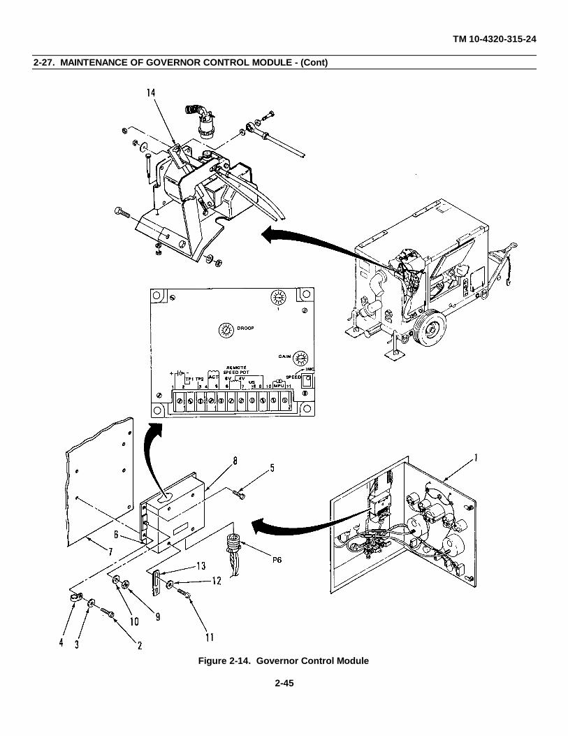
a. REMOVE. (Figure 2-14)
(1) Open control panel door (1).
(2) Remove screw (2), washer (3), and support clip (4) holding wiring harness.
(3) Disconnect electrical connector, P6.
(4) Remove screws (5) and governor control module (4).
b. INSTALL.
(1) Install governor control module (6) on back wall of control panel (7). Secure with screws (5).
(2) Connect electrical connector, P6.
(3) Secure wiring harness with support clip (4), washer (3), and screw (2).
c. ADJUST. If governor control module has been replaced or original module is suspected of being out ofadjustment, start the engine and adjust as follows:
(1) Remove cover (8) by removing nuts (9), washers (10), screws (11), washers (12), and support clip (13).
(2) Set the I adjustment at one division and the GAIN adjustment at the third division from zero.
(3) Set the DROOP adjustment to the minimum setting.
(4) Set AUTO THROTTLE rheostat on control panel to mid-range and select SPEED on PRESSURE/SPEEDselector.
(5) Prepare engine for operation. Refer to TM 10-4320-315-10.
(6) Start engine and adjust SPEED potentiometer on control panel until engine is operating at approximately1575 rpm.
2-44
TM 10-4320-315-24
2-27. MAINTENANCE OF GOVERNOR CONTROL MODULE - (Cont)
Figure 2-14. Governor Control Module
2-45
TM 10-4320-315-24
2-27. MAINTENANCE OF GOVERNOR CONTROL MODULE - (Cont)
(7) If system is unstable (oscillates), slightly reduce the I and GAIN settings until oscillation stops.
(8) Turn AUTO THROTTLE rheostat to the IDLE position.
(9) Slowly turn the GAIN adjustment CW until the governor actuator lever again begins to oscillate, then turnback until oscillation stops.
(10) Upset the actuator lever (14) by hand and note how many oscillations it takes for the lever to againstabilize. If not more than 5 oscillations are required to stabilize, adjustment is correct.
(11) If adjustment is not correct (3-5 oscillations in step (10)) reduce the GAIN setting CCW one division andwhile observing the actuator lever turn the I adjustment clockwise until the lever oscillates.
(12) If the lever does not become unstable, upset it by hand.
(13) When the lever oscillates, slowly turn the adjustment CCW until the lever is stable.
(14) Upset the lever again, it should oscillate 3 to 5 times and then become stable.
(15) If unit cannot be adjusted, try another control module and/or troubleshoot the system (malfunction 6).
(16) Reinstall cover (8) on governor control module (6). Secure wiring clip (13) with washers (12), screws (11),washers (10) and nuts (9).
(17) Close control panel door (1).
2-46

TM 10-4320-315-24
2-28. MAINTENANCE OF ENGINE PROTECTION SYSTEM MODULEThis task covers:
a. INSERT FUNCTION b. INSERT FUNCTION c. INSERT FUNCTION
INITIAL SETUP:
Tools Equipment Conditions
General Mechanics Tool Kit Pumping assembly is shutdown (refer to TM 10-4320-(Item 1, Appendix B) 315-10).
Battery assembly is disconnected (para. 2-16).Materials/Parts
Tags (Item 21, Appendix C)
a. REMOVE. (Figure 2-15)
(1) Open control panel door (1).
(2) Tag wires as necessary and disconnect from module (Figure 2-1, Sheet 1).
(3) Remove screw (2), lockwasher (3), and ground wire (4). Tag ground wire (4).
(4) Remove screws (5), lockwashers (6), and module (7).
Figure 2-15. Engine Protection System Module
2-47

TM 10-4320-315-24
2-28. MAINTENANCE OF ENGINE PROTECTION SYSTEM MODULE - (Cont)
b. INSTALL.
(1) As required, clean module mounting surface on control panel.
(2) Mount module (7) to back wall of control panel with screws (5) and washers (6).
(3) Secure ground wire (4) with lockwasher (3) and screw (2). Remove tag.
(4) Connect wires as tagged.
(5) Close control panel door (1).
2-48

TM 10-4320-315-24
2-29. MAINTENANCE OF CONTROL PANEL WIRE HARNESSThis task covers:
a. Remove b. Install c. Repair
INITIAL SETUP:
Tools Equipment Conditions
General Mechanics Tool Kit Pumping assembly is shutdown (refer to TM 10-4320-(Item 1, Appendix B) 315-10).
Battery assembly is disconnected (para. 2-16).Materials/Parts
ReferencesTags (Item 21, Appendix C)Tool Kit, Electric Connector TM 43-0158(Item 5, Appendix B)
a. REMOVE. (Figure 2-16)
(1) Gain access through engine maintenance access door. Tag and disconnect P1 and P9 from J1 and J9behind control panel. Remove damps.
(2) Swing open control panel door (1).
(3) If harness is to be reused, make sure every terminal is identified with connection points before removal.As required, tag untagged connectors.
Figure 2-16. Control Panel Wiring Harness
2-49

TM 10-4320-315-24
2-29. MAINTENANCE OF CONTROL PANEL WIRE HARNESS - (Cont)
(4) Remove harness (2) through conduit (3) of control panel.
(5) Tag and disconnect wiring harness from control panel components. (See Figure 2-1, Sheets 1 and 2)
b. INSTALL.
(1) Connect wiring harness (2) to control panel components (see Figure 2-1, Sheets 1 and 2). Remove tags.
(2) Feed connectors P1 and P9 from front panel through conduit (3) toward pump side. Connect to matingconnectors J1 and J9.
(3) Adjust wiring for best fit.
(4) Close control panel door (1).
c. REPAIR.
Repair of wiring harness consists of replacing damaged terminals, pins, and connectors. Refer to TM 43-0158.
2-50

TM10-4320-315-24
2-30. MAINTENANCE OF GOVERNOR ACTUATOR ASSEMBLY
This task covers: a. Remove b. Install
INITIAL SETUP:
Tools Equipment Conditions
General Mechanics Tool Kit Pumping assembly is shutdown (refer to TM 10-4320-(Item 1, Appendix B) 315-10).
Battery assembly is disconnected (para. 2-16).
Materials/Parts
Tags (Item 21, Appendix C)Lockwashers (TM 10-4320-315-24P)
a. REMOVE. (Figure 2-17)
(1) Open engine access door (1).
(2) Disconnect cable connector (2) from governor actuator assembly (13).
(3) Remove nut (3) and flat washer (4) from auto defeat cable (5).
(4) Remove nut (6), bolt (7), and washers (8) and disconnect rod assembly (9).
(5) Remove governor actuator mounting bolts (10), lockwashers (11), and nuts (12).
(6) Remove governor actuator (13).
(7) Remove nut (14), lockwasher (15), bolt (16), and linkage bracket (17). (Retain for installation of actuator.)
b. INSTALL.
(1) Install linkage bracket (17) with bolt (16), lockwasher (15), and nut (14).
(2) Install governor actuator (13) with mounting bolts (10), lockwashers (11), and nuts (12).
(3) Reconnect rod assembly (9) with bolt (7), washers (8), and nut (6).
(4) Install flat washer (4) and nut (3) on auto defeat cable (5).
(5) Connect cable connector (2) to governor actuator (13).
(6) Close engine access door (1).
2-51

TM 10-4320-315-24
2-30. MAINTENANCE OF GOVERNOR ACTUATOR ASSEMBLY - (Cont)
Figure 2-17. Governor Actuator Assembly
2-52

TM 10-4320-315-24
2-31. MAINTENANCE OF AUTO DEFEAT CABLE
This task covers: a. Remove b. Install
INITIAL SETUP:
Tools Equipment Conditions
General Mechanics Tool Kit Pumping assembly is shutdown (refer to TM 10-4320-(Item 1, Appendix B) 315-10).
a. REMOVE. (Figure 2-18)
(1) Open engine access door (1).
(2) Push handle (11) in and turn to lock.
(3) Remove nut (2) and flat washer (3) from end of cable (4) at governor actuator lever (5).
(4) Loosen nuts (6 and 7) at bracket (8) and pull cable (4) away from bracket.
(5) Remove nuts (6 and 7) and washers (9).
(6) Loosen setscrew (10) and remove handle (11) from cable (4).
(7) Remove nut (12) and O-ring (13).
b. INSTALL.
(1) Install O-ring (13) and nut (12) on cable (4).
(2) Place cable (4) in engine compartment and install handle end of cable (4) into cutout of panel.
(3) Install handle (11) on cable (4) and tighten setscrew (10).
(4) Install washers (9) and nuts (6 and 7) on cable (4).
(5) Position end of cable (4) in bracket (8) and tighten nuts (6 and 7).
(6) Insert end of cable (4) in slot of governor actuator lever (5) and install flat washer (3) and nut (2).
(7) Close engine access door (11).
2-53

TM 10-4320-315-24
2-31. MAINTENANCE OF AUTO DEFEAT CABLE - (Cont)
Figure 2-18. Auto Defeat Cable
2-54
TM 10-4320-315-24
2-31. MAINTENANCE OF MANUAL THROTTLE CONTROL CABLE
This task covers: a. Remove b. Install
INITIAL SETUP:
Tools Equipment Conditions
General Mechanics Tool Kit Pumping assembly is shutdown (refer to TM 10-4320-(Item 1, Appendix B) 315-10).
Materials/Parts
Lockwashers (TM 10-4320-315-24P)
a. REMOVE. (Figure 2-19)
(1) Open engine access door (1).
(2) Loosen screw (2) from cable locking nut (3) and remove wire of cable (4) at fuel injection pump lever (5).
(3) Remove nuts (6), lockwashers (7), bolts (8), and saddle clamp (9) that secure cable (4) to bracket (10).
(4) Remove nut (11) and washer (12).
(5) Remove cable assembly (4) by pulling away from panel.
b. INSTALL.
(1) Install cable assembly (4) into cutout of panel. Secure with washer (12) and nut (11).
(2) Position cable (4) on bracket (10) in engine compartment and secure with saddle clamp (9), bolts (8),lockwashers (7), and nuts (6).
(3) Install wire of cable (4) on fuel injection pump lever (5) with cable locking nut (3) and screw (2).
(4) Close engine access door (1).
2-55
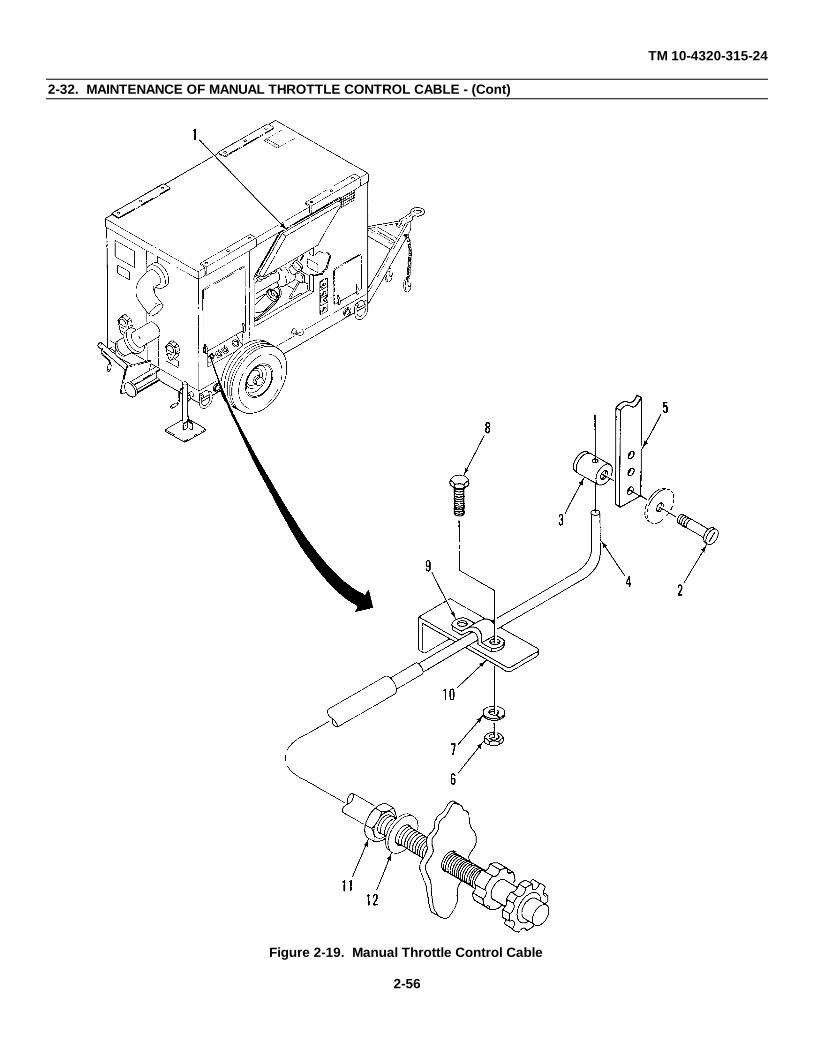
TM 10-4320-315-24
2-32. MAINTENANCE OF MANUAL THROTTLE CONTROL CABLE - (Cont)
Figure 2-19. Manual Throttle Control Cable
2-56
TM 10-4320-315-24
2-33. MAINTENANCE OF COLD START AID HOSE, BOTTLE AND CABLE
This task covers: a. Remove b. Install
INITIAL SETUP:
Tools Equipment Conditions
General Mechanics Tool Kit Pumping assembly is shutdown (refer to TM 10-4320-(Item 1, Appendix B) 315-10).
Materials/Parts
Tags (Item 21, Appendix C)Lockwashers (TM 10-4320-315-24P)
a. REMOVE. (Figure 2-20)
(1) Open air cleaner and engine access doors (1 and 2).
(2) Loosen wing nut (3) on bottle clamp (4). Unscrew and remove ether bottle (5) from actuator (6).
(3) Disconnect hose fitting (7) at actuator (6).
(4) Disconnect hose fitting (8) at engine air intake line (9).
(5) Remove hose assembly (10).
(6) Loosen screw (11) at cable stop nut (12) on actuator lever (13). Loosen clamp (14) and remove wire end ofcable (15).
(7) Remove nuts (16), lockwashers (17), flat washers (18), bolts (19), and bracket (20) with actuator (6).
(8) Pull cable (15) through enclosure panel cutout hole (21) into engine compartment.
(9) Loosen and remove all clamps from cable (15).
(10) Loosen nut (22) and lockwasher (23) at handle (24).
(11) Pull cable (10) through enclosure cutout at control panel.
b. INSTALL.
(1) Install cable (15) through enclosure cutout at control panel.
(2) Secure handle end of cable (15) to enclosure cutout with lockwasher (23) and nut (22).
(3) Insert wire end of cable (15) through panel cutout hole (21) and into air cleaner compartment.
(4) Install clamps on cable (15) in engine compartment.
2-57
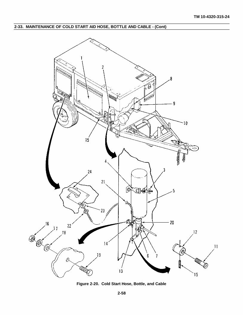
TM 10-4320-315-24
2-33. MAINTENANCE OF COLD START AID HOSE, BOTTLE AND CABLE - (Cont)
Figure 2-20. Cold Start Hose, Bottle, and Cable
2-58

TM 10-4320-315-24
2-33. MAINTENANCE OF COLD START AID HOSE, BOTTLE AND CABLE - (Cont)
(5) Install bracket (20) with actuator (6) onto panel wall with bolts (19), flat washers (18), lockwashers (17), andnuts (16).
(6) Install wire end of cable (15) through clamp (14) and tighten clamp.
(7) Connect wire end of cable (15) to actuator lever (13) with cable stop nut (12) and screw (11).
(8) Connect hose fitting (8) of hose assembly (10) to engine air intake line (9).
(9) Connect hose fitting (7) of hose assembly (10) to actuator (6).
(10) Install ether bottle (5) into actuator (6). Secure ether bottle (5) with clamp (4). Tighten wingnut (3).
(11) Close air cleaner and engine access doors (1 and 2).
2-59
TM10-4320-315-24
2-34. MAINTENANCE OF AIR FILTER GAGE AND HOSE
This task covers: a. Remove b. Install
INITIAL SETUP:
Tools Equipment Conditions
General Mechanics Tool Kit Pumping assembly is shutdown (refer to TM 10-4320-(Item 1, Appendix B) 315-10).
a. REMOVE. (Figure 2-21)
(1) Disconnect hose (1) at air cleaner outlet line (2).
(2) Disconnect other end of hose (1) from air filter gage (3).
(3) Loosen cable clamps and remove hose (1).
(4) Remove screws (4) from top of air filter gage (5). Remove air filter gage (3).
b. INSTALL.
(1) Install air filter gage (3) in cutout of panel. Secure with top part of air filter gage (5) and screws (4).
(2) Connect hose (1) to air filter gage (5).
(3) Install hose (1) in engine compartment and secure with cable clamps.
(4) Install other end of hose (1) to air cleaner outlet line (2).
2-60

TM 10-4320-315-24
2-34. MAINTENANCE OF AIR FILTER GAGE AND HOSE - (Cont)
Figure 2-21.
2-61

TM10-4320-315-24
2-35. MAINTENANCE OF ENGINE WIRING HARNESS
This task covers: a. Remove b. Install
INITIAL SETUP:
Tools Equipment Conditions
General Mechanics Tool Kit Pumping assembly is shutdown (refer to TM 10-4320-(Item 1, Appendix B) 315-10).
Tool Kit, Electric Connector Battery assembly is disconnected (para. 2-16).(Item 5, Appendix B)
References
Materials/PartsTM 43-0158
Tags (Item 21, Appendix C)
a. REMOVE. (Figure 2-22)
(1) Open engine access doors.
Figure 2-22. Engine Wiring Harness
2-62

TM 10-4320-315-24
2-35. MAINTENANCE OF ENGINE WIRING HARNESS - (Cont)
(2) Tag all terminals and plugs not plainly identified (Figure 2-2).
NOTE
Depending on specific task to be performed, all wires may not need to be disconnected.
(2) Disconnect wiring harness from batteries, cranking motor, cranking motor relay, starter pilot relay, governoractuator, magnetic pickup unit, engine temperature switch, lube oil pressure switch, alternator, fuel shutoffvalve, slave receptacle, and engine block.
(3) Disconnect wiring harness from control panel harness at J1.
(4) Remove or loosen cable clamps and cable tie down straps.
(5) Remove wiring harness.
b. INSTALL.
(1) Clean battery terminals and other connecting points as required.
CAUTION
Incorrect wiring may cause equipment damage. Be sure all connections are made as tagged. Ifin doubt, consult schematic diagram.
(2) Connect wiring harness as tagged. Refer to wiring diagram (Figure 2-2) for connection points.
(3) Secure wiring harness with cable ties and clamps.
c. REPAIR.
Repair of wiring harness consists of replacing damaged terminals, pins, and connectors. Refer to 43-0158.
2-63

TM 10-4320-315-24
2-36. MAINTENANCE OF MAGNETIC PICKUP UNIT (MPU)
This task covers: a. Remove b. Install
INITIAL SETUP:
Tools Equipment Conditions
General Mechanics Tool Kit Pumping assembly is shutdown (refer to TM 10-4320-(Item 1, Appendix B) 315-10).
a. REMOVE. (Figure 2-23)
(1) Open engine access door (1).
(2) Disconnect cable (2) from MPU (3).
(3) Loosen jam nut (4).
(4) Unscrew MPU (3) from engine bell housing (5).
b. INSTALL.
(1) Install MPU (3) on engine bell housing (5) until it makes contact with gear tooth, then back off one-quarterturn.
(2) Tighten jam nut (4) maintaining one-quarter turn clearance between MPU and gear tooth.
(3) Connect wiring harness (2) to MPU (3).
(4) Close engine access door (1).
2-64

TM 10-4320-315-24
2-36. MAINTENANCE OF MAGNETIC PICKUP UNIT (MPU) - (Cont)
Figure 2-23. MPU
2-65

TM 10-4320-315-24
2-37. MAINTENANCE OF ENGINE TEMPERATURE AND OIL PRESSURE SWITCHES AND SENDERS
This task covers: a. Remove b. Install
INITIAL SETUP:
Tools Equipment Conditions
General Mechanics Tool Kit Pumping assembly is shutdown (refer to TM 10-4320-(Item 1, Appendix B) 315-10).
Battery assembly is disconnected (para. 2-16).Materials/Parts
Tags (Item 21, Appendix C)Lockwashers (TM 10-4320-315-24P)
a. REMOVE. (Figure 2-24)
(1) Open engine access door.
(2) Remove air cowling cover to engine.
(3) Tag and disconnect wiring harness wire (1) from engine temperature switch (2). Unscrew switch from No. 1cylinder of engine.
(4) Tag and disconnect wiring harness (3) from oil pressure switch (4). Unscrew switch from side of oil filterhousing (5).
(5) Remove nut (6) and washer (7). Tag and disconnect wiring harness wire (8) from engine temperature sender(9). Unscrew sender from top of oil filter housing (5).
(6) Remove nut (10), lockwasher (11), and flat washer (12). Tag and disconnect wiring harness wire (13) fromoil temperature sender (14). Unscrew sender from pipe tee at engine block (15).
b. INSTALL.
(1) Install oil temperature sender (14) in pipe tee at engine block (15). Connect wiring harness wire (13) tosender with nut (10). Remove tag.
(2) Install engine temperature sender (9) into top of oil filter housing (5). Connect wiring harness wire (8) tosender with washer (7) and nut (6). Remove tag.
(3) Install oil pressure switch (4) into side of oil filter housing (5). Connect wiring harness wire (3) to switch andremove tag.
(4) Install engine temperature switch (2) into No. 1 cylinder of engine. Connect wiring harness wire (1) to switchand remove tag.
(5) Install air cowling cover.
(6) Close engine access door.
2-66

TM 10-4320-315-24
2-37. MAINTENANCE OF ENGINE TEMPERATURE AND OIL PRESSURE SWITCHES AND SENDERS - (Cont)
Figure 2-24. Engine Temperature and Oil Pressure Switches and Senders
2-67

TM 10-4320-315-24
2-31. MAINTENANCE OF FUEL VALVES AND LINES
This task covers: a. Remove b. Install
INITIAL SETUP:
Tools Equipment Conditions
General Mechanics Tool Kit Pumping assembly is shutdown (refer to TM 10-4320-(Item 1, Appendix B) 315-10).
Battery assembly is disconnected (para. 2-16).Materials/Parts
Tags (Item 21, Appendix C)Teflon Tape (Item 22, Appendix C)Tie Straps (Item 20, Appendix C)Lockwashers (TM 10-4320-315-24P)
a. REMOVE. (Figure 2-25)
(1) Disconnect fuel lines as follows:
(a) Cut tie wraps in fuel lines.
(b) Disconnect fuel supply line (1) at fitting (2) of fuel selector valve (3) and fitting (4) at engine fueltransfer pump (5). Drain line in suitable container.
(c) Disconnect fuel supply line (6) at fuel tank fitting (7) and fitting (8) of fuel selector valve (3). Drain linein suitable container.
(d) Disconnect fuel supply line (9) at fitting (10) of auxiliary fuel supply (11) and fitting (12) of fuel selectorvalve (3).
(e) Disconnect fuel return line (13) at fitting (14) of fuel return selector valve (15) and at fuel tank returnfitting (16). Drain line in suitable container.
(f) Disconnect fuel return line (17) at fitting (18) of fuel return selector valve (15) and at fitting (19) ofauxiliary fuel discharge (20).
(g) Disconnect fuel return line (21) at fitting (22) of fuel return selector valve (15). Disconnect other end offuel return line (21) at No. 1 engine injector fuel return (23) by removing banjo bolt (24) and sealwashers (25). Drain line in suitable container.
(2) Remove fuel selector valves as follows:
(a) If required, tag and disconnect fuel lines.
(b) Remove screw (26) and handle (27).
(c) Remove capscrews (28), lockwashers (29), and fuel selector valve (3 and/or 15) from enclosure panel.
2-68

TM 10-4320-315-24
2-38. MAINTENANCE OF FUEL VALVES AND LINES - (Cont)
Figure 2-25. Fuel Valves and Lines
2-69

TM 10-4320-315-24
2-38. MAINTENANCE OF FUEL VALVES AND LINES - (Cont)
(3) Remove auxiliary fuel connectors as follows:
(a) If required, tag and disconnect fuel lines.
(b) Remove fitting (30) from auxiliary fuel connector (11 and/or 20).
(c) Remove nut (31) and auxiliary fuel connector (11 and/or 20) with cap (32).
b. INSTALL.
(1) Replace auxiliary fuel connectors as follows:
(a) Install auxiliary fuel connector (11 and/or 20) in cutout of enclosure panel. Secure with nut (31).
(b) Install fitting (30) in auxiliary fuel connector (11 and/or 20).
(c) Connect fuel lines and remove tags.
(2) Replace fuel selector valves as follows:
(a) Install fuel selector valve (3 and/or 15) in cutout of enclosure panel. Secure with lockwashers (29) andcapscrews (28).
(b) Install handle (27) with screw (26).
(c) Connect fuel lines and remove tags.
(3) Replace fuel lines as follows:
(a) Connect fuel supply line (1) at fitting (2) of fuel selector valve (3) and fitting (4) at engine fuel transferpump (5).
(b) Connect fuel supply line (6) at fuel tank fitting (7) and fitting (8) of fuel selector valve (3).
(c) Connect fuel supply line (9) at fitting (10) of auxiliary fuel supply (11) and fitting (12) of fuel selectorvalve (3).
(d) Connect fuel return line (13) at fitting (14) of fuel return selector valve (15) and at fuel tank returnfitting (16).
(e) Connect fuel return line (17) at fitting (18) of fuel return selector valve (15) and at fitting (19) ofauxiliary fuel return (20).
(f) Connect fuel return line (21) at fitting (22) of fuel return selector valve (15). Connect other end of fuelreturn line (21) at No. 1 engine injector fuel return (23) with banjo bolt (24) and seal washers (25).
2-70

TM 10-4320-315-24
2-39. MAINTENANCE OF AIR CLEANER AND AIR INTAKE LINE
This task covers: a. Removeb. Install
INITIAL SETUP
Tools Equipment Conditions
General Mechanics Tool Kit Pumping assembly is shutdown (refer to TM 10-4320-315-10).
(Item 1, Appendix B)Battery assembly is disconnected (para. 2-16).
Materials/Parts Air filter hose line is disconnected (para.2-34).
Lockwashers (TM 10-4320-315-24P)
a. REMOVE, (Figure 2-26)
(1) Open air cleaner access door.
(2) Disconnect fitting (1) of cold start aid line (2) on air inlet pipe (3).
(3) Loosen hose clamp (4) on intake line elbow (5).
(4) Remove nuts (6), lockwashers (7), flat washers (8), bolts (9), and air cleaner (10).
(5) Loosen hose clamps (11) and remove elbow (12) and intake line (3).
(6) Loosen hose clamps (13) and remove rubber flex hose (14) with pipe (15) from engine turbocharger (17).
(7) Loosen hose clamp (16) and remove elbow (5) from pipe (15).
b. INSTALL.
(1) Install rubber flex hose (14) with pipe (15) on engine turbocharger (17) with hose clamps (13).
(2) Install elbow (5) on pipe (15) with hose clamp (16).
(3) Install elbow (12) and intake line (3) on air cleaner (10) with hose clamps (11).
(4) Install air cleaner (10) in air cleaner compartment with bolts (9), flat washers (8), lockwashers (7), andnuts (6).
(5) Secure intake line elbow (5) on air inlet pipe (3) with hose clamp (4).
(6) Connect fitting of cold start aid line (2) on air inlet pipe (3).
(7) Close air cleaner access door.
2-71

TM 10-4320-315-24
2-39. MAINTENANCE OF AIR CLEANER AND AIR INTAKE LINE - (Cont)
Figure 2-26. Air Cleaner
2-72

TM 10-4320-315-24
2-40. MAINTENANCE OF ENGINE OIL DRAIN LINE
This task covers: a. Removeb. Install
INITIAL SETUP
Tools Equipment Conditions
General Mechanics Tool Kit Pumping assembly is shutdown (refer to TM 10-4320-(Item 1, Appendix B) 315-10).
Battery assembly Is disconnected (para. 2-16).Materials/Parts
ReferencesTeflon Tape (Item 22, Appendix C)
LO 10-4320-315-12
a. REMOVE. (Figure 2-27)
(1) Open engine access door (1).
(2) Remove cap (2) and drain oil from engine. Refer to LO 10-4320-315-12.
Figure 2-27. Engine Oil Drain Line
2-73

TM 10-4320-315-24
2-40. MAINTENANCE OF ENGINE OIL DRAIN LINE - (Cont)
(3) Disconnect hose fitting (3) from fitting (4).
(4) Remove nut (5) and flat washer (6) from fitting (4). Remove fitting (4) from cutout of noise enclosure panel (7).
(5) Remove elbow fitting (8) from fitting (4).
(6) Remove nut (9), flat washer (10), and star washer (11) from fitting (4).
(7) Disconnect hose fitting (12) from oil pan fitting (13) and remove hose (14) from engine compartment.
b. INSTALL.
(1) Apply teflon tape to threads of hose fittings.
(2) Place hose (14) in engine compartment. Connect hose fitting (12) to oil pan fitting (13).
(3) Install star washer (11), flat washer (10), and nut (9) on fitting (4).
(4) Install elbow fitting (8) on fitting (4).
(5) Position fitting (4) into cutout of noise enclosure panel (7). Secure with flat washer (6) and nut (5).
(6) Connect hose fitting (3) to fitting (4).
(7) Install cap (2) on elbow fitting (8).
2-74

TM 10-4320-315-24
2-41. MAINTENANCE OF V-BELTS
This task covers: a. Removeb. Install
INITIAL SETUP
Tools Equipment Conditions
General Mechanics Tool Kit Pumping assembly is shutdown (refer to TM 10-4320-(Item 1, Appendix B) 315-10).
Battery assembly is disconnected (para. 2-16).
a. REMOVE. (Figure 2-28)
(1) Open engine access doors (1 and 2).
(2) Push up on idle pulley (3) and relieve tension to the cooling blower V-belt (4).
(3) Remove cooling blower V-belt (4).
(4) Loosen the two adjustment bolts (5) for the alternator V-belt adjustment.
(5) Remove alternator V-belt (6).
b. INSTAL.
(1) Position alternator V-belt (6) on inside groove of crankshaft pulley (7) and alternator pulley (8).
(2) Pull up on alternator (9) until V-belt (6) is tight.
(3) Tighten the two hex adjustment bolts (5).
(4) Position cooling blower V-belt (4) on cooling blower pulley (10) and outside groove of crankshaft pulley (7).
(5) Push up on idler pulley (3) and install V-belt (4) on idler pulley.
c. ADJUSTMENT.
(1) Check tension of alternator V-belt (6) midway between alternator pulley (8) and crankshaft pulley (7).
(2) Check belt deflection. Deflection is 1/2-inch (12.7 mm).
(3) Loosen the hex adjustment bolts (5) if the deflection is not correct.
(4) Move alternator (9) until correct deflection on V-belt (6) is obtained. Tighten the two hex adjustment bolts (5).
2-75

TM 10-4320-315-24
2-41. MAINTENANCE OF V-BELTS - (Cont)
Figure 2-28. V-Belts
2-76

TM 10-4320-315-24
2-42. MAINTENANCE OF COOLING BLOWER ASSEMBLY
This task covers: a. Remove c. Inspect e. Assemblyb. Disassembly d. Repair f. Install
INITIAL SETUP
Tools Equipment ConditionsGeneral Mechanics Tool Kit Pumping assembly is shutdown (refer to TM 10-4320-
(Item 1, Appendix B) 315-10).Torque Wrench, V-belt is removed (para. 2-41).
(Item 2, Appendix B)
Materials/Parts
Grease, General Purpose(Item 8, Appendix C)
a. REMOVE. (Figure 2-29)
(1) Unlatch and remove the removable air cowling (1).
(2) Remove nuts (2), flat washers (3), hex bolts (4), and the air feed (5).
(3) Remove sealing gasket (6) from air feed (5).
(4) Remove the hex bolts (7) and flat washers (8) holding cooling blower (9) to front cover (25) of engine.
(5) Remove cooling blower (9).
b. DISASSEMBLY.
(1) Remove hex bolts (10), flat washers (11), pipe clamps (12), sealing section (13), and sealing brush (14).
(2) Remove nut (15) and pulley bolt (16) from pulley (17). Remove pulley.
(3) Remove impeller (18).
(4) Remove impeller shaft (19).
(5) Remove circlip (20).
(6) Remove bearings (21 and 22) and spacer sleeve (23).
c. INSPECT
Inspect all components for cracks, chips, burrs, and other visible damage. Replace damaged components.
d. REPAIR.
Repair is accomplished by replacement of parts.
2-77

TM 10-4320-315-24
2-42. MAINTENANCE OF COOLING BLOWER ASSEMBLY - (Cont)
e. ASSEMBLY.
(1) Pack two new bearings (21 and 22) with bearing grease.
(2) Install bearing (21) in blower housing (24) with enclosed side of bearing (21) toward the outside of the blower housing (24).
Figure 2-29. Cooling Blower Assembly
2-78

TM 10-4320-315-24
2-42. MAINTENANCE OF COOLING BLOWER ASSEMBLY - (Cont)
(3) Insert spacer sleeve (23) on impeller shaft (19).
(4) Insert impeller shaft (19) into installed bearing (21).
(5) Fill the space between spacer sleeve (23) and blower housing (24) half full of bearing grease.
(6) Install second bearing (22) into blower housing (24), with open side of bearing toward spacer sleeve (23).
(7) Install circlip (20) in groove.
(8) Install impeller (18) on impeller shaft (19), wide flange facing outward.
(9) Install pulley (17) on pulley bolt (16).
(10) Install pulley bolt (16) through impeller shaft (19).
(11) Install nut (15) on pulley bolt (16).
(12) Torque nut (15) on pulley bolt (16) to 22 ft. lbs (29.8 N.m).
(13) Torque nut on pulley bolt 30 ft. lbs (41.9 Nom).
(14) Torque nut on pulley bolt 60 ft. lbs (83.8 Nom).
(15) Position replacement sealing brush (14) and sealing section (13) onto air feed (5). Secure with pipe clamps (12), flat washers (11), and hex bolts (10).
f. INSTALL.
(1) Position cooling blower (9) on front cover (10).
(2) Secure cooling blower (9) with hex bolts (7).
(3) Apply adhesive to sealing gasket (6) and install on air feed (5).
(4) Install air feed (5) onto cooling blower with hex bolts (4), flat washers (5) and nuts (2).
(5) Install removable air cowling (1).
2-79

TM 10-4320-315-24
2-43. MAINTENANCE OF FUEL FILTER ASSEMBLY
This task covers: a. Removeb. Install
INITIAL SETUP
Tools Equipment Conditions
General Mechanics Tool Kit Pumping assembly is shutdown (refer to TM 10-4320-(Item 1, Appendix B) 315-10).
Battery assembly is disconnected (para. 2-16).
a. REMOVE, (Figure 2-30)
(1) Remove fuel filters (2) as follows:
(a) Open drain valves (1) and drain fuel into suitable container.
Figure 2-30. Fuel Filter Assembly
2-80

TM 10-4320-315-24
2-43. MAINTENANCE OF FUEL FILTER ASSEMBLY - (Cont)
(b) Remove drain valves (1).
(c) Unscrew fuel filters (2).
(2) Remove filter base (3) as follows:
(a) Disconnect fuel hoses (4) by removing banjo bolts (5) and seal washers (6).
(b) Remove bolts (7) and washers (8) and filter base (3).
(c) Clean base mounting area.
b. INSTALL.
(1) Install filter base (3) as follows:
(a) Position filter base (3) on engine block. Secure with washers (8) and bolts (7).
(b) Connect fuel hoses (4) with seal washers (6) and banjo bolts (5).
(2) Install fuel filters (2) as follows:
(a) Install filter elements (2) onto filter base (3).
(b) Install drain valves (1) onto fuel filters (2).
2-81

TM 10-4320-315-24
2-44. MAINTENANCE OF V-BELT TENSIONER ASSEMBLY
This task covers: a. Removeb. Install
INITIAL SETUP
Tools Equipment Conditions
General Mechanics Tool Kit Pumping assembly is shutdown (refer to TM 10-4320-(Item 1, Appendix B) 315-10).
Battery assembly is disconnected (para. 2-16).Materials/Parts
O-ring (TM 10-4320-315-24P)
a. REMOVE. (Figure 2-31)
NOTE
V-Belt warning switch is not utilized with control panel on this unit.
(1) Pull plug connector (1) from V-belt warning switch (4).
(2) Remove bolts (2), nut (3), and V-belt warning switch (4).
(3) Remove bolts (5), flat washers (6), and V-belt tensioner assembly (7).
(4) Remove O-ring (8) from V-belt tensioner assembly (7).
b. INSTALL.
(1) Install O-ring (8) on V-belt tensioner assembly (7).
(2) Install V-belt tensioner assembly (7) with flat washers (6) and bolts (5).
(3) Install V-belt warning switch (4) with nut (3) and bolt (2).
(4) Push plug connector (1) onto V-belt warning switch (4).
2-82

TM 10-4320-315-24
2-44. MAINTENANCE OF V-BELT TENSIONER ASSEMBLY - (Cont)
Figure 2-31. V-Belt Tensioner Assembly
2-83

TM 10-4320-315-24
2-45. MAINTENANCE OF TURBOCHARGER OIL INLET TUBE ASSEMBLY
This task covers: a. Removeb. Install
INITIAL SETUP
Tools Equipment Conditions
General Mechanics Tool Kit Pumping assembly is shutdown (refer to TM 10-4320-(Item 1, Appendix B) 315-10).
Battery assembly is disconnected (para. 2-16).Materials/Parts
Tags (Item 21, Appendix C)Gasket (TM 10-4320-315-24P)Lockwasher (TM 10-4320-315-24P)
a. REMOVE, (Figure 2-32)
(1) Remove screw (1), flat washer (2), clamp (3), plate (4) and spacer (5) at flywheel end of engine.
(2) Remove screw (6), lockwasher (7), flat washer (8), clamp (9), plate (10) and spacer (11) at remaining twoclamping positions.
(3) Tag and disconnect wire (12) and remove oil pressure switch (13).
Figure 2-32. Oil Inlet Tube Assembly
2-84

TM 10-4320-315-24
2-45. MAINTENANCE OF TURBOCHARGER OIL INLET TUBE ASSEMBLY - (Cont)
(4) Remove banjo bolts (14) and seal washers (15).
(5) Remove mounting bolts (16) and washers (17) from flanged end of oil inlet tube (18) at turbocharger (21).
(6) Remove oil inlet tube (18) and gasket (19).
b. INSTALL.
(1) Position gasket (19) on mounting flange of turbocharger (20).
(2) Install oil inlet tube (18) on turbocharger (21). Make sure gasket is correctly aligned with flanged end of tube (18) for proper seal.
(3) Install washers (17) and mounting bolts (16) on flanged end of tube (18).
(4) Position oil inlet tube (18) on oil filter base (21).
(5) Secure with seal washers (15) and banjo bolts (14).
(6) Install oil pressure switch (13) and connect wire (12). Remove tag.
(7) Install spacer (5), plate (4), clamp (3), flat washer (2) and screw (1) and secure oil inlet tube (18) at flywheelend of engine.
(8) Install spacer (11), plate (10), clamp (9), flat washer (8), lockwasher (7), and screw (6) and secure oilinlet tube (18) at remaining two clamping positions.
2-85

TM 10-4320-315-24
2-46. MAINTENANCE OF LUBE OIL FILTER ASSEMBLY
This task covers: a. Removeb. Install
INITIAL SETUP
Tools Equipment Conditions
General Mechanics Tool Kit Pumping assembly is shutdown (refer to TM 10-4320-(Item 1, Appendix B) 315-10).
Battery assembly is disconnected (para. 2-16).Materials/Parts
Gaskets (TM 10-4320-315-24P)Filter Element (TM 10-4320-315-24P)
a. REMOVE. (Figure 2-33)
(1) Unscrew filter element (1).
(2) Disconnect and remove oil temperature sensor (2) and oil pressure switches (3) (para. 2-37).
(3) Disconnect oil line by removing banjo bolts (5) and seals (6).
(4) Remove two mounting bolts (7) and flat washers (8) and base assembly (9).
(5) Remove spacer (10) and two gaskets (11).
Figure 2-33. Lube Oil Filter Assembly
2-86

TM 10-4320-315-24
2-46. MAINTENANCE OF LUBE OIL FILTER ASSEMBLY - (Cont)
(6) Remove cap (12).
b. INSTALL.
(1) Install cap (12) on replacement base (9).
(2) Install spacer (10), two gaskets (11), and base assembly (9) on engine with two washers (8) and bolts (7).
(3) Connect oil line (4) with seals (6) and banjo bolt (5).
(4) Install temperature sender (2) and oil pressure switch (3) (para. 2-37).
(5) Connect wiring harness.
(6) Install filter element.
2-87

TM 10-4320-315-24
2-47. MAINTENANCE OF OIL COOLER
This task covers: a. Removeb. Install
INITIAL SETUP
Tools Equipment Conditions
General Mechanics Tool Kit Pumping assembly is shutdown (refer to TM 10-4320-(Item 1, Appendix B) 315-10).
Battery assembly is disconnected (para. 2-16).Parts/Materials
Compression Rings (TM 10-4320-315-24P)Gasket (TM 10-4320-315-24P)
a. REMOVE. (Figure 2-34)
(1) Unlatch and remove cowling cover from engine.
(2) Loosen pipe nuts (1) at inlet and outlet lines (2).
(3) Remove bolts (3), flat washers (4), oil cooler (5), and gasket (6).
(4) Remove compression rings (7) from pipe nuts (1).
Figure 2-34. Oil Cooler
2-88

TM 10-4320-315-24
2-47. MAINTENANCE OF OIL COOLER - (Cont)
b. INSTALL.
(1) Place gasket (6) in position on engine.
CAUTIONPushing the ends of the oil cooler pipes all the way into the block may restrict the flow oflubricating oil and cause damage to engine.
(2) Install compression rings (7) and connect oil cooler pipe nuts (1) as follows:
(a) Make a line 0.315-0.394 in. (8-10 mm) from the end of each pipe.(b) Slide pipe nut (1) and compression ring (7) onto each pipe.(c) While holding the bottom edge of the compression ring (7) on the line, slide pipe nut (1) down to the
compression ring (7). Then mark another line on the pipe flush with the top of the pipe nut (1).(d) Insert each pipe (with pipe nut and compression ring in place) into the block and turn the pipe nut (1)
down until it just touches the top of the compression ring (7).(e) Raise or lower each pipe until the top mark on the pipe is flush with the top of the pipe nut (1). Then
hold the pipe securely in that position and tighten each pipe nut (1).(f) To ensure proper sealing of the compression rings (7), loosen each pipe nut (1) after it has been
tightened. Then tighten pipe nuts (1) down again.
(3) Install flat washers (4) and bolts (3).(4) Install cowling cover on engine.
2-89

TM 10-4320-315-24
2-48. MAINTENANCE OF OIL BREATHER ASSEMBLY
This task covers: a. Removeb. Install
INITIAL SETUP
Tools Equipment Conditions
General Mechanics Tool Kit Pumping assembly is shutdown (refer to TM 10-4320-(Item 1, Appendix B) 315-10).
Battery assembly is disconnected (para. 2-16).Parts/Materials
Sealant (item 15, Appendix C)
a. REMOVE. (Figure 2-35)
(1) Remove capscrews (1), flat washers (2), and muffler access plate (3).
(2) Remove mounting bolt (4), and flat washer (5), oil breather assembly (6), and bracket (7).
(3) Remove bolt (8), flat washer (9), and hose retaining bracket (10) from hose (11).
(4) If necessary, remove hose clamp (12). Remove hose (13) from oil breather assembly (6).
Figure 2-35. Oil Breather Assembly2-90

TM 10-4320-315-24
2-48. MAINTENANCE OF OIL BREATHER ASSEMBLY - (Cont)
b. INSTALL.
(1) If removed, install hose (13) on oil breather assembly (6). Secure connection with hose clamp (12).(2) Install hose retaining bracket (10) on hose (11) with flat washer (9) and bolt (8).(3) Install oil breather assembly (6) and bracket (7) on engine. Install flat washer (5) and mounting bolt (4).(4) Install muffler access plate (3) with flat washers (2) and capscrews (1).
2-91
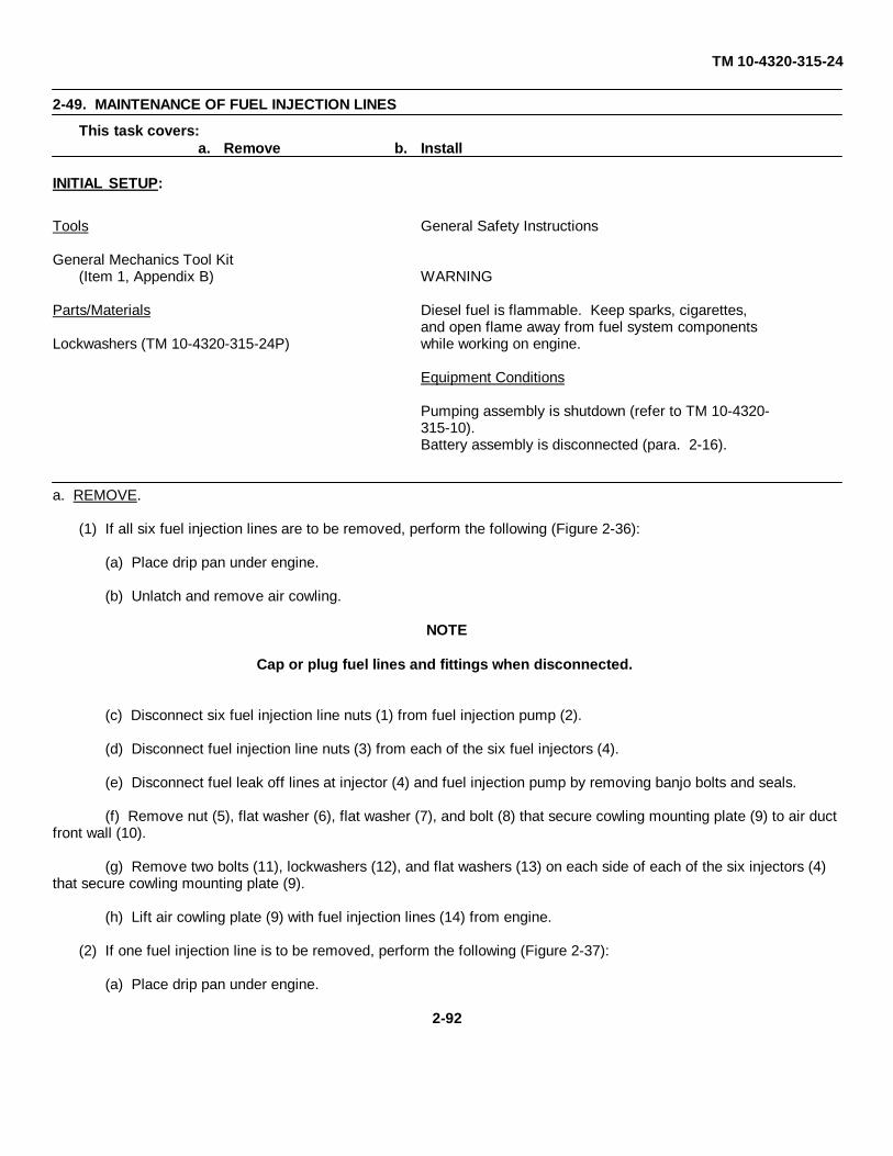
TM 10-4320-315-24
2-49. MAINTENANCE OF FUEL INJECTION LINES
This task covers: a. Remove b. Install
INITIAL SETUP:
Tools General Safety Instructions
General Mechanics Tool Kit(Item 1, Appendix B) WARNING
Parts/Materials Diesel fuel is flammable. Keep sparks, cigarettes,and open flame away from fuel system components
Lockwashers (TM 10-4320-315-24P) while working on engine.
Equipment Conditions
Pumping assembly is shutdown (refer to TM 10-4320-315-10).Battery assembly is disconnected (para. 2-16).
a. REMOVE.
(1) If all six fuel injection lines are to be removed, perform the following (Figure 2-36):
(a) Place drip pan under engine.
(b) Unlatch and remove air cowling.
NOTE
Cap or plug fuel lines and fittings when disconnected.
(c) Disconnect six fuel injection line nuts (1) from fuel injection pump (2).
(d) Disconnect fuel injection line nuts (3) from each of the six fuel injectors (4).
(e) Disconnect fuel leak off lines at injector (4) and fuel injection pump by removing banjo bolts and seals.
(f) Remove nut (5), flat washer (6), flat washer (7), and bolt (8) that secure cowling mounting plate (9) to air ductfront wall (10).
(g) Remove two bolts (11), lockwashers (12), and flat washers (13) on each side of each of the six injectors (4)that secure cowling mounting plate (9).
(h) Lift air cowling plate (9) with fuel injection lines (14) from engine.
(2) If one fuel injection line is to be removed, perform the following (Figure 2-37):
(a) Place drip pan under engine.
2-92

TM 10-4320-315-24
2-49. MAINTENANCE OF FUEL INJECTION LINES - (Cont)
Figure 2-36. Fuel Injector Lines
(b) Unlatch and remove air cowling.
NOTE
Cap or plug fuel line and fitting when disconnected.
(c) Disconnect fuel injection line nut (1) from fitting on fuel injection pump (2).
(d) Disconnect fuel injection line nut (3) from fuel injector (4).
(e) Disconnect fuel leak off line at injector (4) by removing banjo bolt and seals.
(f) Remove bolt (5), nut (7), and lockwasher (6) that secure each line clamp (8) to fuel injection lines.
(g) Push grommet (9) from its slot on cowling mounting plate (10).
(h) Feed fuel injection line (11) through the slot on the cowling mounting plate (10) and remove from engine.
(i) If necessary, remove grommet (9) from fuel injection line (11).
2-93
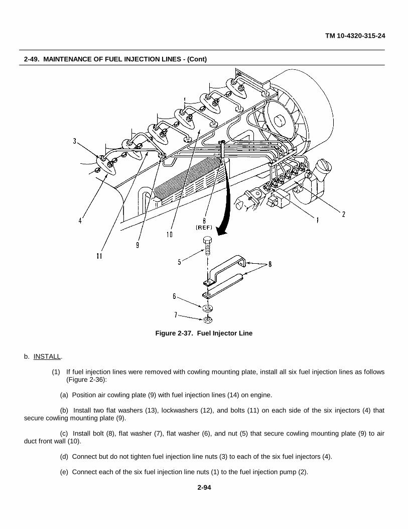
TM 10-4320-315-24
2-49. MAINTENANCE OF FUEL INJECTION LINES - (Cont)
Figure 2-37. Fuel Injector Line
b. INSTALL.
(1) If fuel injection lines were removed with cowling mounting plate, install all six fuel injection lines as follows(Figure 2-36):
(a) Position air cowling plate (9) with fuel injection lines (14) on engine.
(b) Install two flat washers (13), lockwashers (12), and bolts (11) on each side of the six injectors (4) thatsecure cowling mounting plate (9).
(c) Install bolt (8), flat washer (7), flat washer (6), and nut (5) that secure cowling mounting plate (9) to airduct front wall (10).
(d) Connect but do not tighten fuel injection line nuts (3) to each of the six fuel injectors (4).
(e) Connect each of the six fuel injection line nuts (1) to the fuel injection pump (2).
2-94

TM 10-4320-315-24
2-49. MAINTENANCE OF FUEL INJECTION LINES - (Cont)
(f) Tighten all fuel injection line nuts (1 and 3).
(g) Connect fuel leakoff lines to injectors with seal washers and banjo bolts.
(h) Install and latch air cowling.
(i) Bleed fuel system (para. 2-51).
(j) Remove drip pan.
(2) Install one fuel injection line that was removed singularly as follows (Figure 2-37):
(a) Feed fuel injection line (11) into its slot on the cowling mounting plate (10).
(b) Install grommet (9) on fuel injection line (11). Then push grommet (9) into its slot on cowling mountingplate (10).
(c) Install each line clamp (8) on fuel injection lines with lockwasher (6), nut (7), and bolt (5).
(d) Connect but do not tighten fuel injection line nut (3) to fuel injector (4).
(e) Connect fuel injection line nut (1) at fitting of fuel injection pump (2).
(f) Tighten fuel injection line nuts (1 and 3).
(g) Connect fuel leak off line to injector with seal washers and banjo bolt.
(h) Install and latch air cowling.
(i) Bleed fuel system (para. 2-51).
(j) Remove drip pan.
2-95

TM 10-4320-315-24
2-50. MAINTENANCE OF FUEL INJECTORS
This task covers:
a. Remove b. Install
INITIAL SETUP:
Tools Equipment Conditions
General Mechanics Tool Kit Pumping assembly is shutdown (refer to TM 10-4320-
(Item 1, Appendix B) 315-10).Removal Tool 150800, Fuel Injector Battery assembly is disconnected (para. 2-16).
(Item 6, Appendix B) Fuel injection lines removed (para. 2-49).Removal Tool 110030, Fuel Injector
(Item 7, Appendix B)
a. REMOVE. (Figure 2-38)
(1) Disconnect leak off lines (1) from injectors (6) by removing banjo bolts (2) and seal washers (3).
(2) Remove nut (4) and clamping bridge (5) holding each of the six injectors (6).
(3) Using tools 150800 and 110030, remove all injectors (6).
(4) Plug all injector openings.
Figure 2-38. Fuel Injectors
2-96
TM 10-4320-315-24
2-50. MAINTENANCE OF FUEL INJECTORS - (Cont)
b. INSTALL.
(1) Remove plug from injector openings and install injectors (6).
(2) Install clamping bridge (5) on each injector (6). Secure with nut (4).
(3) Connect leak off lines (1) to injectors (6) with seal washers (3) and banjo bolts (2).
2-97

TM 10-4320-315-24
2-51. MAINTENANCE OF FUEL SUPPLY PUMP
This task covers: a. Remove b. Disassemble c. Inspectd. Repair e. Assembly f. Install
INITIAL SETUP:
Tools Equipment Conditions
General Mechanics Tool Kit Pumping assembly is shutdown (refer to TM 10-4320-(Item 1, Appendix B) 315-10).
Fuel lines are disconnected (para. 2-43 and 2-49).Materials/parts
Lockwashers (TM 10-4320-315-24P)O-Ring (TM 10-4320-315-24P)
a. REMOVE. (Figure 2-39)
(1) Remove nuts (1), lockwashers (2), O-ring (3), and fuel supply pump (4) from fuel injection pump (5).
(2) Discard O-ring (3).
b. DISASSEMBLY,
(1) Remove bolt (6), seal washer (7), cover (8), gasket (9), and strainer (10).
(2) Remove screws (11), pump body (12) with diaphragm from pump housing (13).
c. INSPECT.
(1) Clean strainer (10) in diesel fuel. Inspect for tears and holes in strainer (10). Replace if tears or holesare present.
(2) Check pump body (12) with diaphragm and pump housing (13) for visible damage. Replace if damaged.
d. REPAIR.
Repair consists of replacement of defective components only.
e. ASSEMBLY.
(1) Install pump body (12) with diaphragm on pump housing (13) with screws (11).
(2) Install strainer (10), gasket (9), and cover (8) with seal washer (7) and bolt (6).
f. INSTALL.
(1) Position O-ring (3) and fuel supply pump (4) on fuel injection pump (5).
(2) Install lockwashers (2) and nuts (1).
(3) Prime fuel system.
2-98

TM 10-4320-315-24
2-51. MAINTENANCE OF FUEL SUPPLY PUMP - (Cont)
(a) Place suitable container under fuel injection pump (5).
(b) Open overflow valve (14) on fuel injection pump (5).
(c) Actuate manual primer lever (15) on fuel supply pump (4) until fuel emerges free of air bubbles at overflow valve(14).
(d) Tighten overflow valve (14).
Figure 2-39. Fuel Supply Pump
2-99
TM 10-4320-315-24
2-52. MAINTENANCE OF ALTERNATOR
This task covers: a. Remove b. Install
INITIAL SETUP:
Tools Equipment Conditions
General Mechanics Tool Kit Pumping assembly is shutdown (refer to TM 10-4320-(Item 1, Appendix B) 315-10).
Battery assembly is disconnected (para. 2-16).Materials/Parts V-belt is removed (para. 2-41).
Tags (Item 20, Appendix C)
a. REMOVE. (Figure 2-40)
(1) Tag and disconnect wiring to alternator (12).
(2) Remove bolt (1), flat washer (2), nut (3), plate (4), and spacer (5) that secure bracket (6) to alternator (12).
(3) Remove bolt (7), flat washer (8), spacer (9), and bracket (6).
(4) Remove bolt (10) and nut (11) that secure alternator (12) to bracket (13).
(5) Remove bolt (14), nut (15), spacer (16), and flat washer (17) that secure bracket (13) to front cover (18).
(6) Remove bolt (19), spacer (20), and bracket (13).
b. INSTALL.
(1) Install bottom of bracket (13) to front cover (18) with bolt (19) and spacer (20).
(2) Secure top of bracket (13) to front cover (18) with bolt (14), spacer (16), flat washer (17), and nut (15).
(3) Install bracket (6) to front cover (18) with spacer (9), flat washer (8), and bolt (7).
(4) Install alternator (12) on bracket (13) with bolt (10) and nut (11).
(5) Secure alternator (12) to bracket (6) with bolt (1), flat washer (2), spacer (5), plate (4), and nut (3).
(6) Connect wiring to alternator (7). Remove tags.
2-100

TM 10-4320-315-24
2-52. MAINTENANCE OF ALTERNATOR - (Cont)
Figure 2-40. Alternator
2-101

TM 10-4320-315-24
2-53. MAINTENANCE OF STARTER ASSEMBLY
This task covers: a. Remove b. Install
INITIAL SETUP:
Tools Equipment Conditions
General Mechanics Tool Kit Pumping assembly is shutdown (refer to TM 10-432((Item 1, Appendix B) 315-10).
Torque Wrench (Item 2, Appendix B) Battery is disconnected (para. 2-16).
Materials/Parts
Tags (Item 21, Appendix C)Lockwashers (TM 10-4320-315-24P)
a. REMOVE. (Figure 2-41)
(1) Tag and disconnect wires to starter.
(2) Remove lower bolt (1), lockwasher (2), and wiring bundle (3).
(3) Hold starter in place. Remove two bolts (4), lockwashers (5),and starter (6).
Figure 2-41. Starter Assembly
2-102

TM 10-4320-315-24
2-53. MAINTENANCE OF STARTER ASSEMBLY - (Cont)
c. INSTALL.
(1) Install starter (6) with two lockwashers (5), and bolts (4).
(2) Install lower bolt (1) and lockwasher (2) that secure wiring bundle (3) to starter (6).
(3) Torque bolts (1 and 4) to 75 ft lbs (102 N•m).
(4) Connect wires to starter. Remove tags.
2-103

TM 10-4320-315-24
2-54. MAINTENANCE OF CYLINDER HEAD COVER
This task covers: a. Remove b. Replace
INITIAL SETUP:
Tools Equipment Conditions
General Mechanics Tool Kit Pumping assembly is shutdown (refer to TM 10-4320-(Item 1, Appendix B) 315-10).
Torque Wrench (Item 2, Appendix B)
a. REMOVE. (Figure 2-42)
(1) Remove bolt (1) and washer (2).
(2) Remove cylinder head cover (3) and gasket (4).
b. REPLACE.
(1) Install gasket (4) and cylinder head cover (3) on cylinder head (5).
(2) Install washer (2) and bolt (1).
(3) Torque bolt (1) to 7.3 ft•lbs (10 N•m).
Figure 2-42. Cylinder Head Cover
2-104

TM 10-4320-315-24
2-55. MAINTENANCE OF CYLINDER HEAD ASSEMBLY
This task covers: a. Adjust
INITIAL SETUP:
Tools Equipment Conditions
General Mechanics Tool Kit Pumping assembly is shutdown (refer to TM 10-4320-(Item 1, Appendix B) 315-10).
Cylinder head covers removed (para. 2-54).
ADJUST. (Figure 2-43)
(1) Turn crankshaft pulley counterclockwise (CCW) until both valves at No. 1 cylinder are overlapping.
(2) Adjust the valves indicated in Detail A that are adjustable as follows:
(a) Loosen locknut of adjusting bolt (1) on valve.
Figure 2-43. Valve Adjustment
2-105

TM 10-4320-315-24
2-55. MAINTENANCE OF CYLINDER HEAD ASSEMBLY - (Cont)
(b) Insert 0.006 in. (0.15 mm) feeler gage (2) between rocker arm (3) and valve stem (4).
(c) Turn adjusting bolt (1) until light pressure is felt as feeler gage (2) is moved back and forth.
(d) Tighten locknut. Recheck adjustment and readjust if necessary.
(3) After all valves are adjusted in Detail A, rotate crankshaft pulley CCW further by 360°.
(4) Adjust the valves indicated in Detail B that are adjustable.
2-106

TM 10-4320-315-24
2-56. MAINTENANCE OF BRAKE ACTUATOR
This task covers: a. Remove b. Install
INITIAL SETUP:
Tools Equipment Conditions
General Mechanics Tool Kit Pumping assembly is shutdown (refer to TM 10-4320-(Item 1, Appendix B) 315-10).
Materials/Parts
Cotter Pin (TM 10-4320-315-24P)
a. REMOVE. (Figure 2-44)
Figure 2-44. Brake Actuator
2-107

TM 10-4320-315-24
2-56. MAINTENANCE OF BRAKE ACTUATOR - (Cont)
(1) Remove cotter pin (1) and washer (2) from master pin (3) and remove master pin (3) and rear rollers (4).
(2) Remove ball coupler (28) from outer case assembly (29) by sliding forward.
(3) Remove cotter pin (5), damper pin (6), and damper (7).
(4) Remove the self-tapping hex bolts (8).
(5) Disconnect brake pressure hose (9) from steel brake line (10). Drain brake fluid. Then disconnect andremove hose from master cylinder fitting (11).
(6) Remove master cylinder fitting (11).
(7) Remove cap (12) from master cylinder (14). Then remove cover (13) and install cap (12).
(8) Remove master cylinder (14).
(9) Remove the nuts (15), washers (16) and springs (17) from the hex bolts (18). Remove pushrod (19) andcylinder mounting plate (20).
(10) Remove front roller pin (23) by withdrawing cotter pin (21), washer (22) and removing front roller pin fromouter case assembly (29). Remove front roller (24) and cover (25).
(11) Remove breakaway spring (26) and lever (27).
b. INSTALL.
(1) Clean paint from damper pin (6) and master pin (3).
(2) Install damper (7) in ball coupler (28) by inserting damper pin (6) through ball coupler and damper. Securewith cotter pin (5).
(3) Install ball coupler (28) into outer case assembly (29).
(4) Install rear rollers (4) (bevel edge outward) in outer case assembly (29). Line up the rollers with thedamper plunger holes and the master pin holes. Insert the master pin (3) and secure with washer (2) andcotter pin (1).
(5) Install the front roller (24), roller cover (25), and the front roller pin (23). Secure with washers (22) andcotter pin (21).
(6) Attach cylinder mounting plate (20) to master cylinder (13) by inserting hex bolts (18) through cylindermounting plate and master cylinder.
(7) Install springs (17), washers (16), and nuts (15).
(8) Install pushrod (19) into master cylinder (13).
(9) Install breakaway lever (27) and spring (26) into notch at top of outer case assembly.
(10) Install master cylinder (13) into outer case (29) and secure with self-tapping hexagonal bolts (8). Ensurebreakaway lever (27) and spring (26) are aligned.
2-108

TM 10-4320-315-24
2-56. MAINTENANCE OF BRAKE ACTUATOR - (Cont)
(11) Install fitting (11) on master cylinder (13).
(12) Remove cap (12) and install cover (14) over master cylinder (13). Replace cap (12).
(13) Connect brake pressure hose (9) to fitting (11) on master cylinder (13).
(14) Connect brake pressure hose (9) to steel brake line (10).
(15) Bleed and refill master cylinder (para. 2-57).
2-109

TM 10-4320-315-24
2-57. MAINTENANCE OF MASTER CYLINDER AND BRAKE LINES
This task covers: a. Service b. Remove c. Install
INITIAL SETUP:
Tools Equipment Conditions
General Mechanics Tool Kit Pumping assembly is shutdown (refer to TM 10-4320-(Item 1, Appendix B) 315-10).
Materials/Parts Personnel Required
Brake Fluid (Item 5, Appendix C) Two
a. SERVICE. (Figure 2-45)
(1) Fill master cylinder (1) with brake fluid.
(2) Loosen road side wheel cylinder bleeder screw (4).
(3) Person no. 1: alternately apply and release pressure on the actuator (3) by pushing and pulling on trailerlunette (2).
(4) Person no. 2: open bleeder screw (4) as pressure is applied. Close before the recovery stroke begins.
(5) Continue bleeding the system until fluid flowing from line is free of air bubbles.
(6) Tighten road side wheel cylinder bleeder screw (4).
(7) Loosen curb side wheel cylinder bleeder screw. Repeat steps (4) through (6) for curb side wheel.
(8) Recheck master cylinder (1) fluid level. Refill as required.
(9) Apply pressure to brake actuator (3) and check system for leaks.
NOTE
Refer to MAINTENANCE OF BRAKE ACTUATOR (para. 2-56) for procedures for removing mastercylinder.
b. REMOVE.
(1) Disconnect front brake hose assembly (5) from metal brake line (6).
(2) Drain brake fluid into pan and discard; remove hose assembly (5) from master cylinder (1).
(3) Remove clamp (7) securing brake line (6) to trailer chassis (8).
2-110

TM 10-4320-315-24
2-57. MAINTENANCE OF MASTER CYLINDER AND BRAKE LINES-(Cont)
Figure 2-45. Master Cylinder and Brake Lines
2-111

TM 10-4320-315-24
2-57. MAINTENANCE OF MASTER CYLINDER AND BRAKE LINES-(Cont)
(4) Disconnect rear brake fitting (9) connecting brake line (6) to tee (10).
(5) Disconnect brake hose (11) from backing plate on curb side wheel and tire assembly.
(6) Disconnect other end of brake hose (11) from tee (10). Remove brake hose.
(7) Remove two clamps (12) on brake line (13).
(8) Disconnect brake line (13) from brake hose (11) on road side wheel and tire assembly.
(9) Disconnect brake hose (11) from backing plate on road side wheel and tire assembly.
(10) Disconnect other end of brake line (13) from tee (10). Remove brake line and tee.
c. INSTALL.
(1) Connect brake line (13) to tee (10).
(2) Secure brake line (13) to trailer chassis with two clamps (12).
(3) Connect brake hose (11) to brake line (12) and to backing plate on road side wheel and tire assembly.
(4) Connect brake hose (11) to backing plate on curb side wheel and tire assembly and to tee (10).
5) Install brake line (6) on trailer chassis and secure with clamp (7). Connect rear brake fitting (9) to tee (10).
(6) Connect hose assembly (5) to brake line (6) and to master cylinder (1).
(7) Fill master cylinder (1) with brake fluid and bleed brake system (para. a.).
2-112
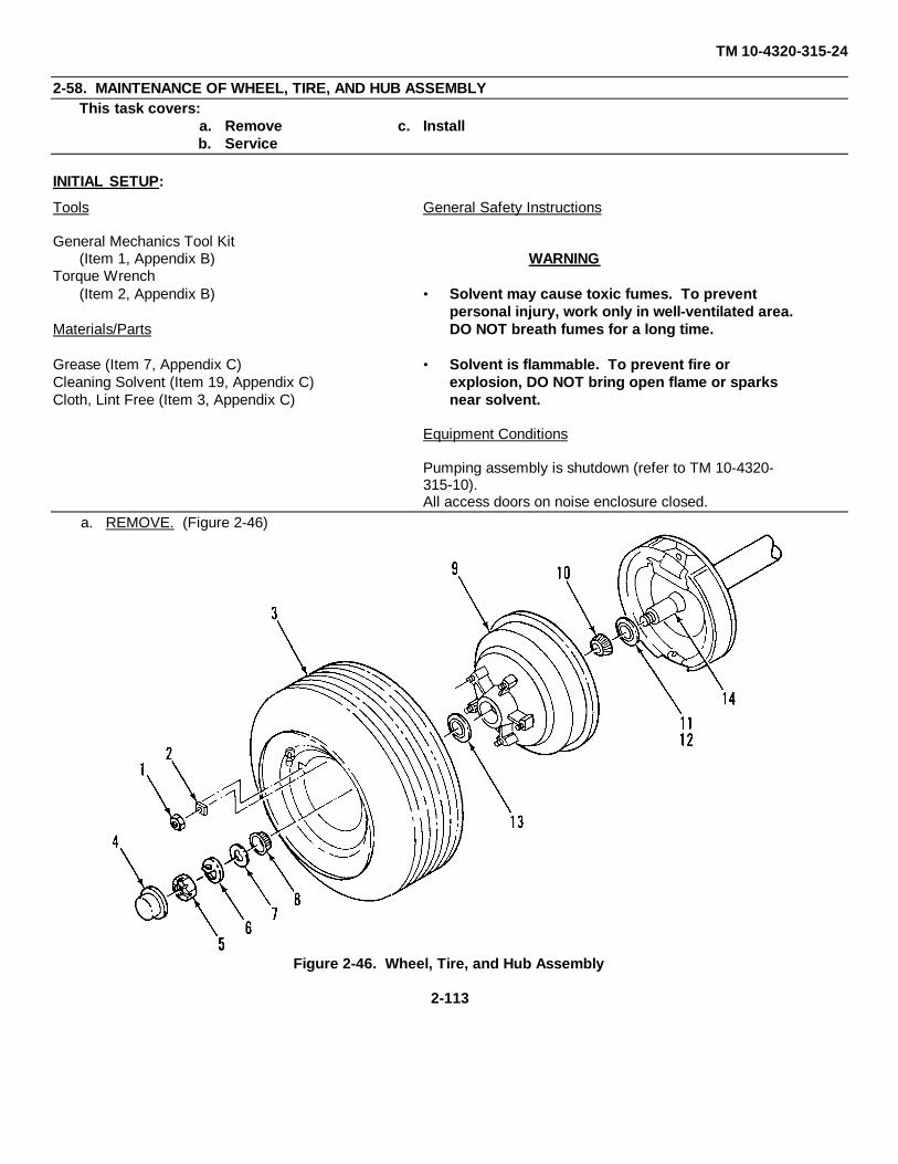
TM 10-4320-315-24
2-58. MAINTENANCE OF WHEEL, TIRE, AND HUB ASSEMBLYThis task covers:
a. Remove c. Installb. Service
INITIAL SETUP:
Tools General Safety Instructions
General Mechanics Tool Kit(Item 1, Appendix B) WARNING
Torque Wrench(Item 2, Appendix B) • Solvent may cause toxic fumes. To prevent
personal injury, work only in well-ventilated area.Materials/Parts DO NOT breath fumes for a long time.
Grease (Item 7, Appendix C) • Solvent is flammable. To prevent fire orCleaning Solvent (Item 19, Appendix C) explosion, DO NOT bring open flame or sparksCloth, Lint Free (Item 3, Appendix C) near solvent.
Equipment Conditions
Pumping assembly is shutdown (refer to TM 10-4320-315-10).All access doors on noise enclosure closed.
a. REMOVE. (Figure 2-46)
Figure 2-46. Wheel, Tire, and Hub Assembly
2-113

TM 10-4320-315-24
2-58. MAINTENANCE OF WHEEL, TIRE, AND HUB ASSEMBLY-(Cont)
(1) Set handbrake.
(2) Using trailer jacks, support trailer so tire is not touching ground.
(3) Remove nuts (1) and wheel clamps (2).
(4) Remove wheel and tire assembly (3).
(5) Remove dust cap (4).
(6) Remove spindle nut (5), locking washer (6) and washer (7).
(7) Release handbrake.
(8) Pull hub assembly (9) outward to loosen and remove outer bearing (8)..
(9) Using bearing drift, tap small end of hub (9) and remove inner bearing (10), race (11), and grease seal(12).
(10) Using bearing drift, tap large end of hub (9) and remove outer bearing race (13).
b. SERVICE.
(1) Wipe all grease from spindle (14) and hub (9).
(2) Inspect bearings (8 and 10) for pitting, scratches, wear, and other damage. If found, replace entire bearingassembly.
WARNING
• Solvent may cause toxic fumes. To prevent personal injury, work only in well-ventilated area.DO NOT breath fumes for a long time.
• Solvent is flammable. To prevent fire or explosion, DO NOT bring open flame or sparks nearsolvent.
(3) If bearings (8 and 10) are to be reused, clean thoroughly with solvent and lint-free cloth. Repack withgrease.
c. INSTALL.
(1) Install inner bearing (10) and race (11) in hub. Install grease seal (12).
(2) Install outer bearing race (13) in hub.
2-114

TM 10-4320-315-24
2-58. MAINTENANCE OF WHEEL, TIRE, AND HUB ASSEMBLY-(Cont)
CAUTION
Do not force hub and tire assembly on spindle. Forcing could cause bearing damage.
(3) Install hub assembly (9) on spindle (14).
(4) Install outer bearing (8), washer (7), locking washer (6), and spindle nut (5).
(5) Tighten spindle nut (5) until there is a slight bind, then back off to nearest locking hole in spindle nut.
(6) Bend tab of locking washer to lock position.
(7) Install dust cap (4).
(8) Place wheel and tire assembly (3) on hub (9) with valve out located halfway between two studs of hub.
(9) Install wheel clamps (2) and nuts (1). Hand tighten.
(10) Tighten in an every-other-one sequence to 20 ft•lbs (21.1 N•m). Continue tightening around wheel in thesame order. Increase torque by 10 ft•lbs (13.6 N•m) each time until each bolt is torqued to 90 ft•lbs (122N•m).
(11) Lower trailer to ground.
2-115

TM 10-4320-315-24
2-59. MAINTENANCE OF BRAKE SHOES AND WHEEL CYLINDERSThis task covers:
a. Remove c. Adjustb. Install
INITIAL SETUP:
Tools Equipment Conditions
General Mechanics Tool Kit Wheel, tire, and hub assembly removed (para. 2-58).(Item 1, Appendix B)
a. REMOVE. (Figure 2-47)
(1) Remove lever and top shoe springs (1 and 2) and washer (3).
(2) Remove side shoe spring (4).
(3) Remove shoe holddown cups (5 and 8), springs (6 and 9) and pins (7 and 10).
(4) Remove bolt (11) and locknut (12) and slide brake shoe assemblies off wheel hub.
(5) Disconnect (unhook) parking brake cable (13) from handbrake actuating lever (14).
(6) Remove adjusting screw spring (15), adjusting screw assembly and socket (16).
NOTE
Replace brake shoes if brake lining is worn down to rivets.
(7) Remove snapring (17), spring washer (18) and flat washer (19) from pin (23). Remove pin (23), hand-brake bracket (22), and flat washer (21) from rear brake shoe (20).
(8) Disassemble front shoe assembly as follows:
(a) Remove snapring (24), pin (25), and handbrake actuating lever (26) from front brake shoe (27).
(b) Remove nut (28), bolt (29), and brake shoe bracket (30) from brake shoe (27).
(9) Inspect wheel cylinder (31) for leaks. If cylinder leaks, disconnect hydraulic line from wheel cylinder, andremove two screws and cylinder.
b. INSTALL.
(1) If removed, install wheel cylinder (31) with two screws, connect hydraulic line, and position rod on cylinder.
(2) Assemble front shoe assembly as follows:
(a) Install front brake shoe (27) on brake shoe bracket (30) with bolt (29) and nut (28).
2-116
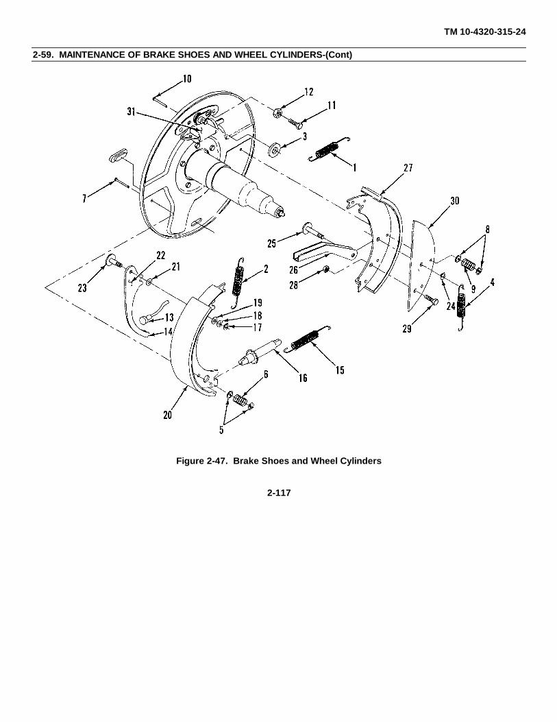
TM 10-4320-315-24
2-59. MAINTENANCE OF BRAKE SHOES AND WHEEL CYLINDERS-(Cont)
Figure 2-47. Brake Shoes and Wheel Cylinders
2-117

TM 10-4320-315-24
2-59. MAINTENANCE OF BRAKE SHOES AND WHEEL CYLINDERS-(Cont)
(b) Install hand brake actuating lever (20) to front brake shoe (27) with pin (25) and snapring (24).
(3) Install handbrake bracket (22) to rear brake shoe (20) as follows:
(a) Insert pin (23) through handbrake bracket (22), flat washer (21) and rear brake shoe (20).
(b) Install flat washer (19), spring washer (18) and snapring (17) on pin (23).
(4) Position adjusting screw assembly and socket (16) between front and rear brake shoe assemblies andinstall adjusting screw spring (15).
(5) Position front and rear brake shoe assemblies on wheel hub. Then secure with bolt (11) and locknut (12).
(6) Connect parking brake cable (13) to handbrake actuating lever (14).
(7) Position front and rear brake shoe assemblies on wheel hub and install pins (7 and 10), springs (6 and 9),and holddown cups (5 and 8).
(8) Install side shoe spring (4).
(9) Install washer (3) and lever and top shoe springs (1 and 2).
(10) Install wheel and hub (para. 2-61).
c. ADJUST.
(1) Remove brake adjustment covers (32).
(2) Using brake adjustment tool or screwdriver, turn starwheel on adjustment mechanism until wheels (33) arelocked.
(3) Turn starwheel in other direction one complete turn. (Wheels should turn freely.)
(4) Reinstall adjustment covers (32).
2-118
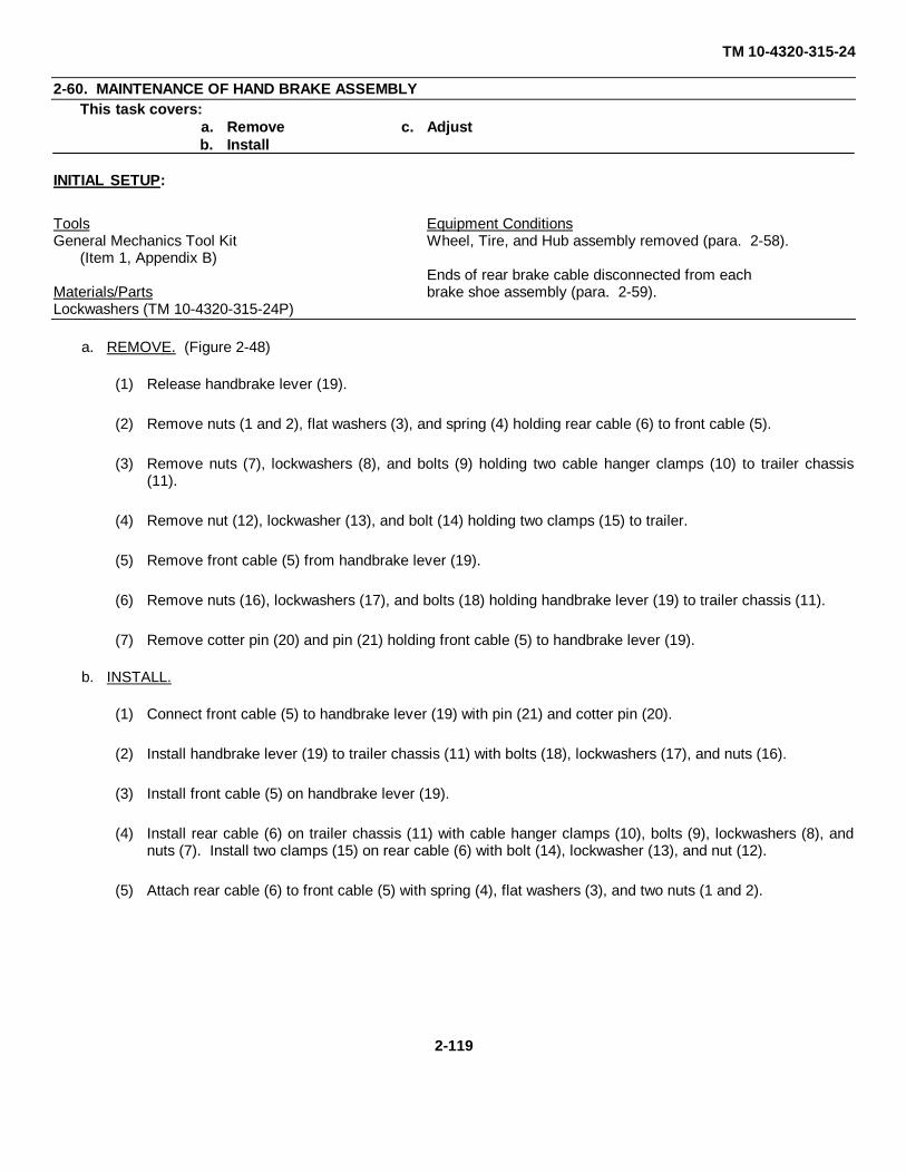
TM 10-4320-315-24
2-60. MAINTENANCE OF HAND BRAKE ASSEMBLYThis task covers:
a. Remove c. Adjustb. Install
INITIAL SETUP:
Tools Equipment ConditionsGeneral Mechanics Tool Kit Wheel, Tire, and Hub assembly removed (para. 2-58).
(Item 1, Appendix B)Ends of rear brake cable disconnected from each
Materials/Parts brake shoe assembly (para. 2-59).Lockwashers (TM 10-4320-315-24P)
a. REMOVE. (Figure 2-48)
(1) Release handbrake lever (19).
(2) Remove nuts (1 and 2), flat washers (3), and spring (4) holding rear cable (6) to front cable (5).
(3) Remove nuts (7), lockwashers (8), and bolts (9) holding two cable hanger clamps (10) to trailer chassis(11).
(4) Remove nut (12), lockwasher (13), and bolt (14) holding two clamps (15) to trailer.
(5) Remove front cable (5) from handbrake lever (19).
(6) Remove nuts (16), lockwashers (17), and bolts (18) holding handbrake lever (19) to trailer chassis (11).
(7) Remove cotter pin (20) and pin (21) holding front cable (5) to handbrake lever (19).
b. INSTALL.
(1) Connect front cable (5) to handbrake lever (19) with pin (21) and cotter pin (20).
(2) Install handbrake lever (19) to trailer chassis (11) with bolts (18), lockwashers (17), and nuts (16).
(3) Install front cable (5) on handbrake lever (19).
(4) Install rear cable (6) on trailer chassis (11) with cable hanger clamps (10), bolts (9), lockwashers (8), andnuts (7). Install two clamps (15) on rear cable (6) with bolt (14), lockwasher (13), and nut (12).
(5) Attach rear cable (6) to front cable (5) with spring (4), flat washers (3), and two nuts (1 and 2).
2-119

TM 10-4320-315-24
2-60. MAINTENANCE OF HAND BRAKE ASSEMBLY-(Cont)
Figure 2-48. Hand Brake Assembly
2-120

TM 10-4320-315-24
2-60. MAINTENANCE OF HAND BRAKE ASSEMBLY-(Cont)
c. ADJUST.
(1) Disengage handbrake lever (19).
(2) Turn adjustment knob on handbrake lever (19) all the way in.
(3) Loosen outer nut (1).
(4) Remove slack from front and rear cables (5 and 6) by adjusting inner nut (2) on front cable (5). Ensurethere is no tension applied.
(5) Tighten outer nut (1) against inner nut (2).
(6) Adjust knob on handbrake lever (19) until handbrake can be engaged.
2-121

TM 10-4320-315-24
2-61. MAINTENANCE OF WIRING HARNESS AND TAIL LIGHTS.This task covers:
a. Removeb. Install
INITIAL SETUP:
Tools Equipment Conditions
General Mechanics Tool Kit Pumping assembly is shutdown (refer to TM 10-4320-(Item 1, Appendix B) 315-10).
Materials/PartsLockwashers (TM 10-4320-315-24P)
a. REMOVE. (Figure 2-49)
(1) Remove tail lights as follows:
(a) Open engine access doors.
(b) Disconnect wire connectors (1) to tail light (5).
(c) Remove nuts (2), lockwashers (3), ground wire (4), and plate (5) holding tail light (6) to panel (7).Remove tail light.
(d) Remove screws (8) and lens plate (9) on tail light assembly (6).
(e) If necessary, remove bulbs (10).
(f) Perform steps (b) through (e) and remove the second tail light.
(2) Remove wiring harness as follows:
(a) Remove nut (11) that secures elbow (12) to floor of chassis. Remove elbow (12) and tail light wires (13) tobelow chassis.
(b) Loosen compression nut (14) from elbow (12). Remove elbow (12) from tail light wires (13).
(c) Remove nut (15), lockwasher (16), flat washer (17), and bolt (18) that secure clamp (19) on cable harness(20).
(d) Pull wiring harness (20) out from cable route on curbside of trailer chassis (21).
b. INSTALL.
(1) Install wiring harness as follows:
(a) Route wiring harness (20) onto trailer chassis (21) starting at front of trailer.
(b) Pull end of wiring harness (20) aft through openings in cable route of trailer chassis (21).
2-122

TM 10-4320-315-24
2-61. MAINTENANCE OF WIRING HARNESS AND TAIL LIGHTS-(Cont)
Figure 2-49. Wiring Harness and Tail Lights
2-123

TM 10-4320-315-24
2-61. MAINTENANCE OF WIRING HARNESS AND TAIL LIGHTS-(Cont)
(c) Install clamp (19) on wiring harness (20) with bolt (18), flat washer (17), lockwashers (16) and nut(15).
(d) Route wiring harness (20) over axle (22).
(e) Feed tail light wires (13) through elbow (12). Secure with compression nut (14).
(f) Position tail light wires (13) and threaded end of elbow (12) up through trailer chassis (21). Securewith nut (11).
(2) Install tail lights as follows:
(a) If removed, install bulbs (10).
(b) Install lens plate (9) on tail light (6) with screws (8).
(c) Install tail light (6) on rear panel (7) with plate (5), ground wire (4), lockwashers (3), and nuts (2).
(d) Connect wire connectors (1) to each tail light (6).
2-124

TM 10-4320-315-24
2-62. MAINTENANCE OF LEVELING JACKS AND TRIPOD JACK ASSEMBLYThis task covers:
a. Removeb. Install
INITIAL SETUP:
Tools Equipment Conditions
General Mechanics Tool Kit Pumping assembly is shutdown (refer to TM 10-4320-(Item 1, Appendix B) 315-10).
Materials/Parts
Lockwashers (TM 10-4320-315-24P)
a. REMOVE. (Figure 2-50)
(1) Remove leveling jacks as follows:
(a) Remove all weight from leveling jack to be removed.
(b) Drive out pin (1).
(c) Remove leveling jack (2) from trailer bracket (7).
(d) Remove nut (3), lockwasher (4), bolt (5) and pad (6) from leveling jack (2). Note position of pad.
(2) Remove tripod jack assembly as follows:
(a) Remove all weight from tripod jack assembly (8).
(b) Remove locknuts (9) and bolts (10) holding A-frame (11) to brackets (12).
(c) Remove snapring (13) holding tripod jack (14) to front jack bracket (15).
(d) Remove tripod jack assembly (7).
(e) Remove nut (16), lockwasher (17), bolt (18), and tripod jack (14) from A-frame (11).
(f) Remove nut (19), lockwasher (20), bolt (21), and pad (22) from A-frame (11).
(g) Remove bolts (23), nuts (24), lockwashers (25), and brackets (12) from chassis (26).
b. INSTALL.
(1) Install tripod jack assembly as follows:
(a) Install bracket (12) on chassis (26) with bolts (23), lockwashers (25) and nuts (12).
(b) Attach pad (22) to A-frame (11) with bolt (21), lockwasher (20), and nut (19).
(c) Attach tripod jack (14) to A-frame (11) with bolt (18), lockwasher (17), and nut (16).2-125

TM 10-4320-315-24
2-62. MAINTENANCE OF LEVELING JACKS AND TRIPOD JACK ASSEMBLY-(Cont)
Figure 2-50. Leveling Jacks and Tripod
2-126

TM 10-4320-315-24
2-62. MAINTENANCE OF LEVELING JACKS AND TRIPOD JACK ASSEMBLY-(Cont)
(c) Position tripod jack assembly (8) on trailer chassis.
(d) Secure tripod jack (14) to front jack bracket (15) with snapring (13).
(e) Secure A-frame (11) to brackets (12) with bolts (10), and locknuts (9).
(2) Replace leveling jacks as follows:
(a) Install pad (6) onto leveling jack with bolt (5), lockwasher (4), and nut (3).
(b) Install leveling jack (2) onto trailer bracket (7). Secure with pin (1).
2-127

TM 10-4320-315-24
2-63. MAINTENANCE OF SHOCK ABSORBERSThis task covers:
a. Removeb. Install
INITIAL SETUP:
Tools Equipment Conditions
General Mechanics Tool Kit Pumping assembly is shutdown (refer to TM 10-4320-(Item 1, Appendix B) 315-10).
Materials/Parts
Lockwashers (TM 10-4320-315-24P)
a. REMOVE. (Figure 2-51)
(1) Using trailer jacks, support trailer and remove tension from shock absorbers.
(2) Remove nut (1), lockwasher (2), and bolt (3) holding shock absorber lower end (4) to lower mount (5) ataxle.
(3) Remove nut (6), lockwasher (7), and bolt (8) holding shock absorber upper end (9) to upper mount (10) ontrailer chassis.
(4) Remove shock absorber (11).
Figure 2-51. Shock Absorbers
2-128

TM 10-4320-315-24
2-63. MAINTENANCE OF SHOCK ABSORBERS-(Cont)
b. INSTALL.
(1) Compress shock absorber (11) and install upper end (9) to upper mount (10) of trailer chassis with bolt (8),lockwasher (7), and nut (6).
(2) Extend shock absorber (11) and install lower end (4) to lower mount (5) at axle with bolt (3), lockwasher(2), and nut (1).
2-129

TM 10-4320-315-24
2-64. MAINTENANCE OF REFLECTORSThis task covers:
a. Removeb. Install
INITIAL SETUP:
Tools
General Mechanics Tool Kit(Item 1, Appendix B)
Drill, Electric, Portable, 1/4 inch(Item 2, Appendix B)
Riveter, Blind(NSN 5120-00-017-2849)
Materials/Parts
Sealant (Item 14, Appendix C)Rivets (TM 10-4320-315-24P)
a. REMOVE. (Figure 2-52)
(1) Select the same diameter drill bit as the install blind rivets (1).
(2) Drill through center of rivet (1) just deep enough to sever rivet head from shank.
(3) Remove reflector (2) and remainder of rivet (1) with a pin punch.
Figure 2-52. Reflector
2-130

TM 10-4320-315-24
2-64. MAINTENANCE OF REFLECTORS.
b. INSTALL.
(1) Wet rivet (1) with sealant.
(2) Position reflector (2) on chassis (3).
(3) Using hand blind riveter on blind rivet stem, mount reflector (2) on chassis with just enough force to firmlyseat rivet and prevent part separation.
(4) Activate riveter and pull rivet (1) until stem of rivet breaks.
2-131/(2-132 blank)

TM 10-4320-315-24
CHAPTER 3DIRECT SUPPORT MAINTENANCE INSTRUCTIONS
PARAGRAPH TITLE PARAGRAPH
Common Tools and Equipment .................................................................................................................................... 3-1Direct Support Troubleshooting .................................................................................................................................... 3-4Repair Parts ................................................................................................................................................................. 3-3Special Tools; Test, Measurement, and Diagnostic Equipment;
and Support Equipment ............................................................................................................................................ 3-2
Section I. REPAIR PARTS, SPECIAL TOOLS, TMDEAND SUPPORT EQUIPMENT
3-1. Common Tools and Equipment. Appendix B, Section III contains the authorized common tools. For authorizedequipment, refer to Modified Table of Organization and Equipment (MTOE) applicable to your unit.
3-2. Special Tools; Test, Measurement, and Diagnostic Equipment; and Support Equipment. No special tools;test, measurement, and diagnostic equipment; or support equipment are required for the repair of the pumping assembly.
3-3. Repair Parts. Repair parts are listed and illustrated in the Repair Parts and Special Tools List (RPSTL), TM 10-4320-315-24P.
Section II. DIRECT SUPPORT TROUBLESHOOTING
3-4. Direct Support Troubleshooting. Table 3-1 contains troubleshooting information for locating and correcting mostof the operating troubles which are the responsibility of direct support maintenance. Each malfunction for an individualcomponent, unit, or system is followed by a list of tests or inspections which will help you to determine probable causesand corrective actions to take. Perform the tests/inspections and corrective actions in the order listed.
This manual cannot list all malfunctions that may occur, nor all tests or inspections and corrective actions. If amalfunction is not listed or is not corrected by listed corrective actions, notify your supervisor.
Only those functions within the scope of direct support maintenance are listed. For troubleshooting procedures within thescope of unit maintenance, refer to Table 2-2.
SYMPTOM INDEX
TroubleshootingProcedure
(Para)
Engine Cranks, But Does Not Start ................................................................................................................................. 1Low Power in the Engine ................................................................................................................................................. 2Engine Knocks ................................................................................................................................................................ 3Engine Oil Consumption Excessive ................................................................................................................................. 4
3-1

TM 10-4320-315-24
Table 3-1. Direct Support Troubleshooting
MALFUNCTIONTEST OR INSPECTION
CORRECTIVE ACTION
1. ENGINE CRANKS, BUT DOES NOT START.
Step 1. Check cylinder compression.
Adjust rocker arm assembly (para. 2-55).
Remove injector nozzles (para. 2-50).
Install compression gauge in one nozzle hole.
Crank engine over and note compression.
Remove compression gauge from cylinder already checked and install in the other cylinders.
Crank engine over and note compression.
Compression of cylinders should be approximately 319-362 psi (2199-2496 kPa) and shouldbe within 15 percent of each other. If not within specification, refer to general supportmaintenance.
NOTE
These compression figures may vary considerably depending on cranking speed, altitudeand ambient temperature. The most reliable indication of a properly functioning engine isone in which the compression of each cylinder is within 10 psi (68.94 kPa) of the other andone in which the addition of a small amount of motor oil in the cylinder does not significantlyincrease either the compression or difference in compression between the cylinders.
Step 2. Check timing of fuel injection pump (para. 3-18).
2. LOW POWER IN THE ENGINE.
Step 1. Check for blown or leaky head seals.
Replace defective head seals (para. 3-30).
Step 2. Check for poor compression. Refer to malfunction 1, step 2.
If poor compression, refer to general support maintenance.
Step 3. Check timing of fuel injection pump (para. 3-18).
3-2

TM 10-4320-315-24
Table 3-1. Direct Support Troubleshooting - (Cont)
MALFUNCTIONTEST OR INSPECTION
CORRECTIVE ACTION
3. ENGINE KNOCKS.
Step 1. Check for blown or leaky head gasket.
Replace defective head seals (para. 3-30).
Step 2. Check for poor compression. Refer to malfunction 1, step 2.
If poor compression, refer to general support maintenance.
4. ENGINE OIL CONSUMPTION EXCESSIVE.
Step 1. Check for poor compression. Refer to malfunction 1, step 2.
If poor compression, refer to general support maintenance.
Step 2. Check for leaky oil seals.
If seals leak, refer to general support maintenance.
3-3

TM 10-4320-315-24
Section III. DIRECT SUPPORT MAINTENANCE PROCEDURES
PARAGRAPH TITLE PARAGRAPH
Air Cowling and Oil Cooler Discharge Duct ................................................................................................................ 3-24Air Outlet Frame ........................................................................................................................................................ 3-22Alternator ................................................................................................................................................................... 3-19Axle, Springs, and Suspension Kit .............................................................................................................................. 3-34Crankshaft Pulley and Damper ................................................................................................................................... 3-27Cylinder Heads ........................................................................................................................................................... 3-30Engine and Pump Assembly ...................................................................................................................................... 3-17Exhaust Pipes and Muffler ......................................................................................................................................... 3-16Flywheel ..................................................................................................................................................................... 3-25Flywheel Housing ....................................................................................................................................................... 3-26Front Mount Plate and Mounting Feet ........................................................................................................................ 3-28Fuel Injection Pump ................................................................................................................................................... 3-18Intake and Exhaust Manifolds .................................................................................................................................... 3-23Interior Brace ............................................................................................................................................................. 3-15Introduction .................................................................................................................................................................. 3-5Noise Enclosure ........................................................................................................................................................... 3-6Noise Enclosure Battery Access Panel ....................................................................................................................... 3-13Noise Enclosure Control Panel ................................................................................................................................... 3-14Noise Enclosure Front Panel ...................................................................................................................................... 3-10Noise Enclosure Interior Panels .................................................................................................................................. 3-11Noise Enclosure Left Panel ........................................................................................................................................ 3-12Noise Enclosure Rear Panels ....................................................................................................................................... 3-8Noise Enclosure Right Panel ........................................................................................................................................ 3-9Noise Enclosure Roof ................................................................................................................................................... 3-7Pump . ........................................................................................................................................................................ 3-32Pump Discharge Line ................................................................................................................................................. 3-32Pump Suction Line ..................................................................................................................................................... 3-31Rocker Arm Assembly ................................................................................................................................................ 3-29Safety Chains ............................................................................................................................................................. 3-35Starter ........................................................................................................................................................................ 3-20Turbocharger ............................................................................................................................................................. 3-21
3-5. Introduction . This section contains instructions covering maintenance functions for the direct support levelmaintenance on the pumping assembly.
NOTE
Personnel required are listed only if the task requires more than one. Tables 3-3, 3-4, and 3-5contain maintenance specifications, torque specifications and dimensions and clearances.Table 3-4 also indicates how various angles can be readily obtained by comparison with a clockface. They are included in this chapter as an aid to personnel performing maintenanceprocedures. After completing each maintenance procedure, perform an operational check toensure that equipment is properly functioning.
3-4
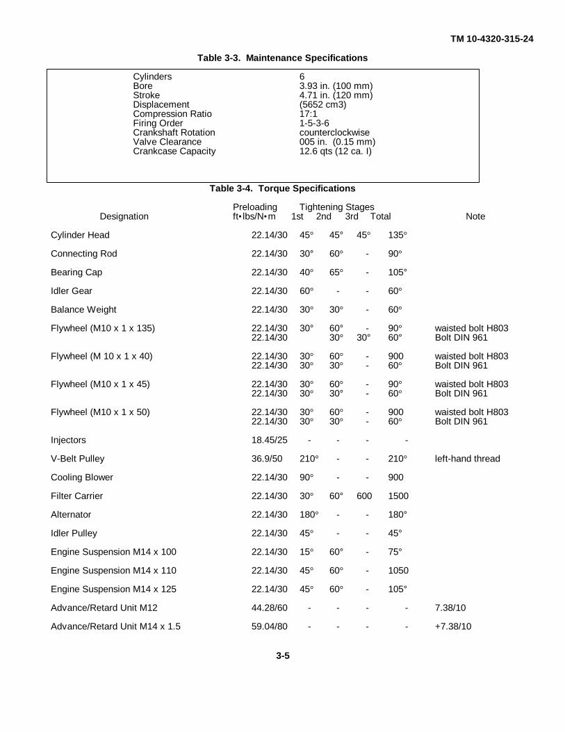
TM 10-4320-315-24
Table 3-3. Maintenance Specifications
Cylinders 6Bore 3.93 in. (100 mm)Stroke 4.71 in. (120 mm)Displacement (5652 cm3)Compression Ratio 17:1Firing Order 1-5-3-6Crankshaft Rotation counterclockwiseValve Clearance 005 in. (0.15 mm)Crankcase Capacity 12.6 qts (12 ca. I)
Table 3-4. Torque Specifications
Preloading Tightening StagesDesignation ft•lbs/N•m 1st 2nd 3rd Total Note
Cylinder Head 22.14/30 45° 45° 45° 135°
Connecting Rod 22.14/30 30° 60° - 90°
Bearing Cap 22.14/30 40° 65° - 105°
Idler Gear 22.14/30 60° - - 60°
Balance Weight 22.14/30 30° 30° - 60°
Flywheel (M10 x 1 x 135) 22.14/30 30° 60° - 90° waisted bolt H80322.14/30 30° 30° 60° Bolt DIN 961
Flywheel (M 10 x 1 x 40) 22.14/30 30° 60° - 900 waisted bolt H80322.14/30 30° 30° - 60° Bolt DIN 961
Flywheel (M10 x 1 x 45) 22.14/30 30° 60° - 90° waisted bolt H80322.14/30 30° 30° - 60° Bolt DIN 961
Flywheel (M10 x 1 x 50) 22.14/30 30° 60° - 900 waisted bolt H80322.14/30 30° 30° - 60° Bolt DIN 961
Injectors 18.45/25 - - - -
V-Belt Pulley 36.9/50 210° - - 210° left-hand thread
Cooling Blower 22.14/30 90° - - 900
Filter Carrier 22.14/30 30° 60° 600 1500
Alternator 22.14/30 180° - - 180°
Idler Pulley 22.14/30 45° - - 45°
Engine Suspension M14 x 100 22.14/30 15° 60° - 75°
Engine Suspension M14 x 110 22.14/30 45° 60° - 1050
Engine Suspension M14 x 125 22.14/30 45° 60° - 105°
Advance/Retard Unit M12 44.28/60 - - - - 7.38/10
Advance/Retard Unit M14 x 1.5 59.04/80 - - - - +7.38/10
3-5

TM 10-4320-315-24
Table 3-4. Torque Specifications - (Cont)
Table 3-5. Dimensions and Clearances
CamshaftBearing Tolerance 0.016 - 0.028 in. (0.4064 - 0.7112 mm)End Play 0.015 - 0.027 in. (0.4 - 0.7mm)Lift 0.31 in. (Bmm)Bearing Diameter (Front) 1.890 - 1.893 in. (48.01 - 48.08mm)Bearing Diameter (Rear) 1.890 - 1.893 in. (48.01 - 48.08mm)Journal Diameter (Front) 1.57 in. (40mm)Journal Diameter (Rear) 1.57 in. (40mm)Gear Backlash 0.008 - 0.010 in. (0.22 - 0.27mm)
Connecting RodsBearing Clearance 0.006 in. (0.15mm)Side Clearance 0.018 - 0.022 in. (0.48 - 0.58mm)
CrankshaftMain Bearing Journal Diameter 2.873 - 2.874 in. (72.971 - 72.990mm)Connecting Rod Journal Diameter 2.519 - 2.478 In. (63.971 - 62.990mm)Main Bearing Clearance 0.002 - 0.004 in. (0.052 - 0.11mm)Out of Round 0.00019 in. (0.0050mm)Pin Width 1.457 1.461 in. (37.0 - 37.1mm)
3-6

TM 10-4320-315-24
3-6. MAINTENANCE OF NOISE ENCLOSURE
INITIAL SETUP:
Tools General Safety Instructions
Riveter, Blind(NSN 5120-00-017-2849) WARNING
Drill, Electric, Portable 114 inchCap, with Drill Bits Safety glasses shall be worn when drilling out rivets(Item 3, Appendix B) to prevent small particles from entering the eyes
and causing serious Injury .Materials/Parts
Sealant (Item 15, Appendix C)Rivets (TM 10-4320-315-24P)
REPAIR. (Figure 3-1)
(1) Remove blind rivets as follows:
(a) Select drill bit (1) the same diameter (2) as installed blind rivet (3).
(b) Hold electric drill (4) perpendicular to the surface to prevent enlargement or damage to existing hole.
(c) Drill through center of rivet just deep enough to sever rivet head (5) from shank (6).
(d) Remove remainder of rivet (3) with a pin punch.
(e) Deburr rivet hole.
Figure 3-1. Blind Rivet Removal/Installation
3-7

TM 10-4320-315-24
3-6. MAINTENANCE OF NOISE ENCLOSURE - (Cont)
(2) Install blind rivets as follows:
(a) Select proper diameter and length of blind rivet (6).
(b) Select appropriate nose piece (7) for hand blind riveter (8) and install nose piece.
(c) Wet rivet (6) with sealant.
(d) Holding hand blind riveter (8) at right angle to work, install riveter (8) on blind rivet stem (9).
(e) Push against work with just enough force to firmly seat rivet (6) and prevent part separation.
(f) Actuate riveter (8) and pull rivet (6) until stem (9) breaks.
3-8

TM 10-4320-315-24
3-7. MAINTENANCE OF NOISE ENCLOSURE ROOF
This task covers: a. Remove b. Install
INITIAL SETUP:
Tools Equipment Conditions
General Mechanics Tool Kit Pumping assembly is shutdown with leveling jacks(Item 1, Appendix B) and tripod jack assembly in the operating position(refer to TM 10-4320-315-10).
Materials/PartsPersonnel Required
Lockwashers (TM 10-4320-315-24P)Four
a. REMOVE. (Figure 3-2)
(1) Loosen hose clamps (1) and disconnect air discharge hose (2) from air baffle (3) and engine.
(2) Remove bolts (4), flat washers (5), and roof (6).
(3) Remove bolts (7), nuts (8), lockwashers (9), and brackets (10) from roof (6).
b. INSTALL.
(1) Install brackets (10) to roof (6) with bolts (7), lockwashers (9), and nut (8).
(2) Position roof (6) over noise enclosure panels. Secure with flat washers (5) and bolts (4).
(3) Connect air discharge hose (2) to air baffle (3) and engine with clamps (1).
3-9

TM 10-4320-315-24
3-7. MAINTENANCE OF NOISE ENCLOSURE ROOF - (Cont)
Figure 3-2. Noise Enclosure Roof
3-10

TM 10-4320-315-24
3-8. MAINTENANCE OF NOISE ENCLOSURE REAR PANELS
This task covers: a. Remove b. Install
INITIAL SETUP:
Tools Equipment Conditions
General Mechanics Tool Kit Tail light assemblies and ground wire disconnected(Item 1, Appendix B) (para 2-61).
Roof removed (para. 3-7).Materials/Parts
Lockwashers (TM 10-4320-315-24P)
a. REMOVE. (Figure 3-3)
(1) Remove priming pipe (1).
(2) Remove drain pipe (2).
(3) Remove bolts (3) and flat washers (4) at side panels (5).
(4) Remove bolts (6) and flat washer (7).
(5) Remove left (8) and right (9) center plates.
(6) Remove bolts (10) and flat washers (11).
(7) Remove bolt (12), flat washer (13), drain cap chain (14), and flat washer (15).
(8) Remove left (16) and right (17) rear panels.
(9) Remove bolts (18), flat washers (19), lockwashers (20), and nut (21).
(10) Remove panel mounting bracket (22).
b. INSTALL.
(1) Install panel mounting bracket (22). Install flat washers (19), bolts (18), lockwashers (20), and nuts (21).
(2) Install left (16) and right (17) rear panels with flat washers (11) and bolts (10).
(3) Secure drain cap chain (14) with flat washers (13 and 15) and bolt (12).
(4) Install left (8) and right (9) center plates. Secure with flat washers (7) and bolts (6).
(5) Install flat washers (4) and bolts (3) at side panels (5).
(6) Install drain pipe (2).
(7) Install priming pipe (1).
3-11

TM 10-4320-315-24
3-8. MAINTENANCE OF NOISE ENCLOSURE REAR PANELS - (Cont)
Figure 3-3. Rear Panels
3-12
TM 10-4320-315-24
3-9. MAINTENANCE OF NOISE ENCLOSURE RIGHT PANEL
This task covers: a. Remove b. Install
INITIAL SETUP:
Tools Equipment Conditions
General Mechanics Tool Kit Roof removed (para. 3-7).(Item 1, Appendix B) Fuel valves and lines removed (para. 2-38).
Materials/Parts
Rivets (TM 10-4320-315-24P)Lockwashers (TM 10-4320-315-24P)
a. REMOVE. (Figure 3-4)
(1) Remove bolts (1) and flat washers (2) at sides of right panel (9).
(2) Remove bolts (3), flat washers (4), nuts (5), and flat washers (6).
(3) Remove bolts (7), flat washers (8), and right panel (9).
(4) Remove rivets (10) and engine access panel door (11) (para. 3-6).
(5) Remove rivets (12) and air filter access panel door (13) (para. 3-6).
(6) Remove bolts (14), flat washers (15), nuts (16), lockwasher (17), and right panel mounting bracket (18).
b. INSTALL.
(1) Install right panel mounting bracket (18).
(2) Install flat washers (15), bolts (14), lockwashers (17), and nuts (16).
(3) Install air filter access panel door (13) with rivets (12) (para. 3-6).
(4) Install engine access panel door (11) with rivets (10) (para. 3-6).
(5) Install right panel (5) in mounting bracket with flat washers (8) and bolts (7).
(6) Install flat washers (4), bolts (3), flat washers (6), and nuts (5).
(7) Install flat washers (2) and bolts (1) at sides of right panel (5).
3-13

TM 10-4320-315-24
3-9. MAINTENANCE OF NOISE ENCLOSURE RIGHT PANEL - (Cont)
Figure 3-4. Right Panel
3-14

TM 10-4320-315-24
3-10. MAINTENANCE OF NOISE ENCLOSURE FRONT PANEL
This task covers: a. Remove b. Install
INITIAL SETUP:
Tools Equipment Conditions
General Mechanics Tool Kit Roof removed (para. 3-7).(Item 1, Appendix B)
Materials/Parts
Rivets (TM 10-4320-315-24P)Lockwashers (TM 10-4320-315-24P)
a.REMOVE. (Figure 3-5)
(1) Remove nut (1), flat washers (2 and 3), and bolt (4) that secures chain (5).
(2) Remove rivets (6) (para. 3-6).
(3) Remove hinged exhaust panel assembly (7).
(4) Open air filter access door (8) and remove shelf (9) above air filter assembly.
(5) Remove bolts (10) and flat washers (11).
(6) Remove front panel (14).
(7) Removebolts (15), flat washers (16), nuts (17), and lockwashers (18).
(8) Remove front panel mounting bracket (19).
(9) Remove rivets (20) (para. 3-6) and support bracket (21).
b. INSTALL.
(1) Install support bracket (21) on front panel (14) with rivets (20) (para. 3-6).
(2) Install front panel mounting bracket (19) with flat washers (16), bolts (15), lockwashers (18), and nuts (17).
(3) Install front panel (7) and secure with flat washers (13) and bolts (12).
(4) Install flat washers (11) and bolts (10).
(5) Install exhaust panel assembly (2) and secure with rivets (6) (para. 3-6).
(6) Secure chain (5) with flat washers (2 and 3), bolt (4), and nut (1).
(7) Install shelf (9) above air filter through access panel door (8).
3-15

TM 10-4320-315-24
3-10. MAINTENANCE OF NOISE ENCLOSURE FRONT PANEL - (Cont)
Figure 3-5. Front Panel and Exhaust Panel Assembly
3-16

TM 10-4320-315-24
3-11. MAINTENANCE OF NOISE ENCLOSURE INTERIOR PANELS
This task covers: a. Remove b. Install
INITIAL SETUP:
Tools Equipment Conditions
General Mechanics Tool Kit Cold start hose, bottle, and cable removed (para.(Item 1, Appendix B) 2-33).
Air intake pipe removed (para. 2-39).Materials/Parts Roof removed (para. 3-7).
Front panel removed (para. 3-10).Lockwashers (TM 10-4320-315-24P) Exhaust pipes and muffler removed (para. 3-16).
a. REMOVE. (Figure 3-6)
(1) Remove rivets (1) (para. 3-6) and air duct sleeve (2). Remove gasket (3).
(2) Remove rivets (4) and air duct (5) for engine blower.
(3) Remove divider panel (6).
(4) Remove panel (7).
(5) Remove rivets (8) (para. 3-6).
(6) Remove divider panel (9).
(7) Remove nuts (10), lockwashers (11), and bolts (12) that secure air duct (13) to engine air discharge duct(14).
(8) Remove rivets (15) (para. 3-6) and support bracket (16).
b. INSTALL.
(1) Install support bracket (16) on divider panel (9) with rivets (15) (para. 3-6).
(2) Install air duct (13) to engine air discharge duct (14) with bolts (12), lockwashers (11), and nuts (10).
(3) Install divider panel (9) in support brackets (17 and 18) and secure with rivets (8) (para. 3-6).
(4) Install panel (7) in support bracket (19).
(5) Install divider panel (6) in support bracket (16).
(6) Install air duct (5) on divider panel (6) with rivets (4) (para. 3-6).
(7) Install air duct sleeve (2) on air duct (5) with rivets (1) (para. 3-6).
3-17
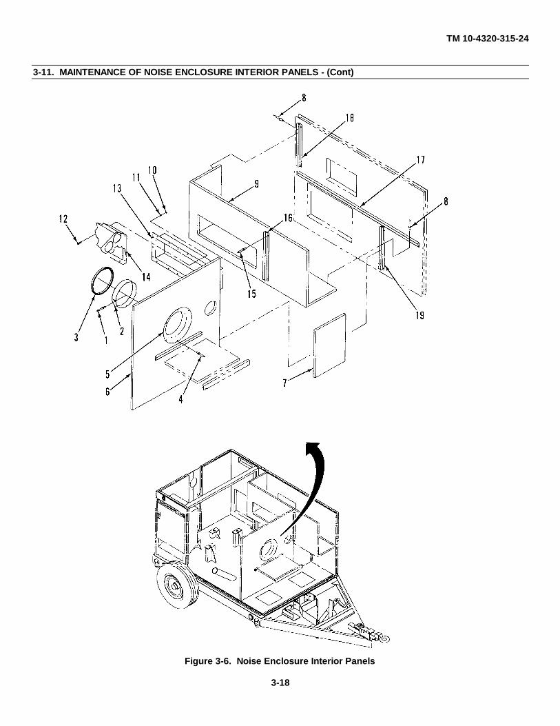
TM 10-4320-315-24
3-11. MAINTENANCE OF NOISE ENCLOSURE INTERIOR PANELS - (Cont)
Figure 3-6. Noise Enclosure Interior Panels
3-18

TM 10-4320-315-24
3-12. MAINTENANCE OF NOISE ENCLOSURE LEFT PANEL
This task covers: a. Removeb. Install
INITIAL SETUP:
Tools Equipment Conditions
General Mechanics Tool Kit Roof removed (para. 3-7).(Item 1, Appendix B) Front panel removed (para. 3-10).
Muffler removed (para. 3-16).Materials/Parts
Lockwashers (TM 10-4320-315-24P)Rivets (TM 10-4320-315-24P)
a. REMOVE. (Figure 3-7)
(1) Remove nut (1), flat washers (2 and 3), and bolt (4) that secure chain (5) for exhaust panel assembly.(2) Remove rivets (6) (para. 3-6).(3) Remove engine access hinged panel (7).(4) Remove bolts (8), flat washers (9), and upper access panel (10).(5) Remove bolts (11) and flat washers (12).(6) Remove bolts (13), nuts (16), and flat washers (14 and 15).(7) Remove bolts (17), flat washers (18), and left panel (19).(8) Remove bolts (20), flat washers (21), nuts (22), lockwashers (23) and mounting bracket (24).
b. INSTALL.
(1) Install mounting bracket (24) with flat washers (21), bolts (20), lockwashers (23), and nuts (22).(2) Install left panel (19) with flat washers (12) and bolts (11). Install flat washers (18) and bolts (17).(3) Secure left panel (19) to interior brace (25) with flat washer (14), bolts (13), flat washers (15), and nuts
(16).(4) Install upper access panel (10) with flat washers (9) and bolts (8).(5) Install engine access hinged panel (7) with rivets (6) (para. 3-6).(6) Secure chain (5) for exhaust panel assembly with flat washers (2 and 3), bolt (4), and nut (1).
3-19

TM 10-4320-315-24
3-12. MAINTENANCE OF NOISE ENCLOSURE LEFT PANEL- (Cont)
Figure 3-7. Left Panel
3-20
TM 10-4320-315-24
3-13. MAINTENANCE OF NOISE ENCLOSURE BATTERY ACCESS PANEL
This task covers: a. Removeb. Install
INITIAL SETUP:
Tools Equipment Conditions
General Mechanics Tool Kit Roof removed (para. 3-7).(Item 1, Appendix B)
Materials/Parts
Rivets (TM 10-4320-315-24P)Lockwashers (TM 4320-315-24P)
a. REMOVE, (Figure 3-8)
(1) Remove rivets (1) (para. 3-6).(2) Remove battery access hinged panel (2).(3) Remove nuts (3), flat washers (4), bolts (5), and flat washers (6).(4) Remove bolts (7) and flat washers (8).(5) Remove bolts (9), flat washers (10), and panel (11).(6) Remove bolts (12), flat washers (13), nuts (14), lockwashers (15), and mounting bracket (16).
b. INSTALL.
(1) Install mounting bracket (16) with flat washers (13), bolts (12), lockwashers (15), and nuts (14).(2) Install panel (11) in mounting bracket (16) and secure with flat washers (10) and bolts (9).(3) Install bolts (7) and flat washers (8).(4) Secure panel (11) to interior brace with flat washers (6), bolts (5), flat washers (4), and nuts (3).(5) Install battery access hinged panel (2) with rivets (1) (para. 3-6).
3-21

TM 10-4320-315-24
3-13. MAINTENANCE OF BATTERY ACCESS PANEL - (Cont)
Figure 3-8. Battery Access Panel
3-22

TM 10-4320-315-24
3-14. MAINTENANCE OF NOISE ENCLOSURE CONTROL PANEL
This task covers: a. Removeb. Install
INITIAL SETUP:
Tools Equipment Conditions
General Mechanics Tool Kit Control panel assembly removed (para. 2-17).(Item 1, Appendix B) Roof removed (para. 3-7).
Manual throttle control cable removed (para. 2-32).Materials/Parts Auto defeat cable removed (para. 2-31).
Air filter gage removed (para. 2-34).Lockwashers (TM 10-4320-315-24P) Cold start cable removed (para. 2-33).Rivets (TM 10-4320-315-24P)
a. REMOVE. (Figure 3-9)
(1) Remove bolts (1) and flat washers (2).(2) Remove bolts (3), flat washers (4), nuts (5), and flat washers (6).(3) Remove bolts (7), flat washers (8), and panel (9).(4) Remove rivets (10) (para. 3-6) and hinged panel (11).(5) Remove bolts (12), flat washers (13), nuts (14), lockwashers (15), and mounting bracket (16).
b. INSTALL.
(1) Install mounting bracket (16) with flat washers (13), bolts (12), lockwashers (15), and nuts (14).(2) Install hinged panel (11) on panel (9) with rivets (10) (para. 3-6).(3) Install panel (9) on mounting bracket (16) with flat washers (8), and bolts (7).(4) Secure panel (9) to interior brace with flat washers (4), bolts (3), flat washers (6), and nuts (5).(5) Install flat washers (2) and bolts (1).
3-23

TM 10-4320-315-24
3-14. MAINTENANCE OF NOISE ENCLOSURE CONTROL PANEL - (Cont)
Figure 3-9. Noise Enclosure Control Panel
3-24

TM 10-4320-315-24
3-15. MAINTENANCE OF INTERIOR BRACE
This task covers: a. Removeb. Install
INITIAL SETUP:
Tools Equipment Conditions
General Mechanics Tool Kit Roof removed (para. 3-7).(Item 1, Appendix B) Noise enclosure control panel removed (para. 3-14).
Battery access panel removed (para. 3-13).Materials/Parts Noise enclosure left panel removed (para. 3-12).
Lockwashers (TM 10-4320-315-24P)Rivets (TM 10-4320-315-24P)
a. REMOVE. (Figure 3-10)(1) Remove bolts (1), flat washers (2), nuts (3), and lockwashers (4) that secure interior brace (5) on each side
of trailer chassis.(2) Remove interior brace (5).
b. INSTALL.(1) Install interior brace (5) on trailer chassis.(2) Secure interior brace on each side of trailer chassis with flat washers (2), bolts (1), lockwashers (4), and
nuts (3).
Figure 3-10. Interior Brace
3-25

TM 10-4320-315-24
3-16. MAINTENANCE OF EXHAUST PIPES AND MUFFLER
This task covers: a. Removeb. Install
INITIAL SETUP:
Tools Equipment Conditions
General Mechanics Tool Kit Roof of noise enclosure removed (para. 3-7).(Item 1, Appendix B)
Materials/Parts
Gaskets (TM 10-4320-315-24P)Lockwashers (TM 10-4320-315-24P)
a. REMOVE. (Figure 3-11)
(1) Remove bolts (1), flat washers (2), and access plate (3).(2) Open hinged exhaust panel assembly (9).(3) Remove nut (4), flat washers (5 and 6), and bolt (7) that secures chain (8) of hinged exhaust panel
assembly (9).(4) Lower hinged exhaust panel assembly (9) to the full open position.(5) Remove bolts (10) and locknuts (11) that secure flange of flexible exhaust pipe (12) to turbocharger flange
(13).(6) Remove nut (14), lockwasher (15), and bolt (16) from each of the four muffler mounts (17).(7) Remove muffler (18).(8) Remove gasket (19).(9) Unscrew and remove flex exhaust pipe (12) from elbow (20).
(10) Unscrew elbow (20) from muffler (18).(11) Remove bolts (21), nuts (22), flat washers (23) and clamps (24) from muffler (18).
b. INSTALL.
(1) Install clamps (24) on muffler (18) with flat washers (23), bolts (21), and nuts (22).(2) Install elbow (20) on threaded pipe of muffler (18).(3) Install threaded end of flexible exhaust pipe (12) on elbow (20).(4) Install gaskets (19) on flexible exhaust pipe (12).
3-26

TM 10-4320-315-24
3-16. MAINTENANCE OF EXHAUST PIPES AND MUFFLER - (Cont)
(5) Position muffler (18) on the four muffler mounts (17) and align flange of flexible exhaust pipe (12) withflange of turbocharger (13). Secure muffler (18) with bolt (16), lockwasher (15), and nut (14) at eachmuffler mount (17).
(6) Secure flange of flexible exhaust pipe (12) to turbocharger flange (13) with bolts (10) and locknuts (11).(7) Secure chain (8) of hinged exhaust panel assembly (9) with bolt (7), flat washers (5 and 6), and nut (4).(8) Install access plate (3) with flat washers (2) and bolts (1).
Figure 3-11. Exhaust Pipes and Muffler
3-27

TM 10-4320-315-24
3-17. MAINTENANCE OF ENGINE AND PUMP ASSEMBLY
This task covers: a. Removeb. Install
INITIAL SETUP:
Tools General Safety Instructions
General Mechanics Tool Kit(Item 1, Appendix B) WARNING
Lifting Eyes (Item 20, Appendix B)Because of the weight and bulk of the engine and
Materials/Parts pump assembly, a minimum of two people arerequired to remove/install this equipment. Failure to
Lockwashers (TM 10-4320-315-24P) comply with this warning could result in death orLoctite (Item 17, Appendix C) serious injury to personnel and damage to equipment.
Personnel Required Equipment Conditions
Two Slave and battery cables disconnected (para. 2-16).Engine controls, wiring harness, and control paneldisconnected (para. 2-29 and 2-35).Air intake line and air intake boot to turbochargerremoved (para. 2-39).Cooling blower air feed removed (para. 2-42).Fuel lines disconnected (para. 2-38).Fuel gage disconnected (para. 2-19).Air discharge duct removed (para. 3-7).Priming and drain pipes removed (para. 3-8).Roof removed (para. 3-7).Rear panels removed (para. 3-8).Interior brace removed (para. 3-15).
NOTE
Engine or pump can be disconnected and removed separately.
a. REMOVE. (Figure 3-12)
(1) Remove pump as follows:
(a) Remove bolts (1) that secure the bearing housing (2) of pump (3) to engine flywheel housing (4).
(b) Remove nuts (5), lockwashers (6), bolts (7), and flat washers (8) from the two pump mounts (11) andisolators (10).
3-28

TM 10-4320-315-24
3-17. MAINTENANCE OF ENGINE AND PUMP ASSEMBLY - (Cont)
Figure 3-12. Engine and Pump Assembly Removal
3-29

TM 10-4320-315-24
3-17. MAINTENANCE OF ENGINE AND PUMP ASSEMBLY - (Cont)
WARNING
Because of the weight and bulk of pump assembly, a minimum of two people are required toremove/install this equipment. Failure to comply with this warning could result in death orserious injury to personnel and damage to equipment.
(c) Using appropriate weight handling equipment, slide pump (3) with flex coupling (12) off pin-studs(13) on engine flywheel (14). Lift pump from trailer.
(d) Remove flat washers (9) and isolators (10) from pump mounts (11).
(2) Remove engine as follows:
(a) Remove nuts (15), lockwashers (16), flat washers (17), and bolts (18) from the engine mounts (21)and isolators (20).
(b) Attach lifting eyes (22) to engine.
(c) Using appropriate weight handling equipment, attach to lifting eye (22) on top of engine and liftengine from trailer.
(d) If necessary, remove pin-studs (13) from engine flywheel (14).
(e) Remove flat washers (19) and isolators (20) from engine mounts (21).b. INSTALL.
(1) Install engine on trailer as follows:(a) If removed, install pin-studs (13) on engine flywheel (14).
(b) Install isolators (20) and flat washers (19) on engine mounts (21).
(c) Attach lifting eyes (22) to engine.
(d) Using appropriate weight handling equipment, attach to lifting eyes (22) on top of engine and liftengine onto trailer.
(e) Insert bolts (18) through each of the four engine mounts (21) and isolators (20) from the top. Securebolts with flat washers (17), lockwashers (16), and nuts (15).
(2) Install pump on trailer as follows:(1) Rotate pump coupling (12) on pump shaft to align with four pin-studs (13) on flywheel (14).
(2) Install isolators (10) and flat washers (9) on pump mounts (11).
(3) Using appropriate lifting equipment, lift and position pump (3) with flex coupling onto pin-studs (13)and engine flywheel housing (14).
3-30

TM 10-4320-315-24
3-17. MAINTENANCE OF ENGINE AND PUMP ASSEMBLY - (Cont)
(4) Install bolts (1) that secure the bearing housing (2) of pump (3) to the engine flywheel housing (4).
(5) Place flat washers (8) on bolts (7) and insert through each of the two pump mounts (11) and isolators(10) from the bottom. Secure bolts with lockwashers (6), and nuts (5).
3-31

TM 10-4320-315-24
3-18. MAINTENANCE OF FUEL INJECTION PUMP
This task covers: a. Removeb. Install
INITIAL SETUP:
Tools Equipment Conditions
General Mechanics Tool Kit No. 1 cylinder head cover removed (para. 2-54).(Item 1, Appendix B) V-belt tensioner assembly removed (para. 2-44).Timing Fixture Manual throttle cable disconnected (para. 2-32).(Item 15, Appendix B) Engine assembly removed (para. 3-17).Magnetic Timing Tool(Item 16, Appendix B) Personnel RequirementsHigh Pressure Hand Pump(Item 17, Appendix B) TwoWaste Fuel Bottle(Item 18, Appendix B) Materials/Parts
Rags (Item 12, Appendix C)
a. REMOVE.
(1) Disconnect control linkage to fuel injection pump.(2) Disconnect oil line (1, Figure 3-13) to fuel injection pump (8). Cap line.(3) Tag and disconnect wires to fuel solenoid. Remove screw (2) and fuel solenoid (3) from fuel injection
pump (10).(4) Disconnect fuel injection lines from fuel injection pump.(5) Disconnect fuel lines at fuel supply pump.
NOTE
Step (6) applies when timing marks are already marked on crankshaft pulley.
(6) Align injection timing mark (1, Figure 3-14) on crankshaft pulley (2) with pointer of timing tool (3) asfollows:
(a) Install timing tool (3) on engine front cover (4). Position pointer so that the pointed end almostcontacts the outside edge of the crankshaft pulley.
(b) Rotate crankshaft pulley clockwise (CW) until valves on No. 1 cylinder overlap. Then turn pulleyCW 3600 (one full turn).
(c) If necessary, align first mark (1) on crankshaft pulley next to pointer of timing tool (3) by rotatingcrankshaft pulley (3) CW.
3-32

TM 10-4320-315-24
3-18. MAINTENANCE OF FUEL INJECTION PUMP - (Cont)
Figure 3-13. Fuel Injection Pump
(d) If first mark (1) is already past pointer of timing tool (3), turn crankshaft pulley (2) counterclockwise(CCW) one-quarter turn to remove gear backlash. Then turn crankshaft pulley (2) CW to aligntiming mark (1) with pointer of timing tool (3).
3-33

TM 10-4320-315-24
3-18. MAINTENANCE OF FUEL INJECTION PUMP - (Cont)
Figure 3-14. Timing Marks and Timing Tool
NOTE
• Replacement crankshaft pulleys do not have timing marks Indented on pulley.
• Magnetic tool (003-1189) is an alternate method of marking crankshaft pulley for timing. Besure magnetic tool is completely centered all the way around the crankshaft pulley.
(8) If crankshaft pulley is to be replaced, locate the true Top Dead Center (TDC) and establish timing marks asfollows:
(a) Install timing tool (3, Figure 3-14) on engine front cover (4). Position pointer so that the pointed endalmost contacts the outside edge of the crankshaft pulley.
(b) Rotate crankshaft pulley CW until valves on No. 1 cylinder overlap. Then turn pulley CW 360° (onefull turn).
(c) Rotate crankshaft pulley one-quarter turn CCW.
(d) Depress exhaust valve down. Then install 6 mm keystock (1, Figure 3-15) between No. 1 exhaustvalve stem (2) face and rocker arm (3).
(e) Rotate crankshaft pulley (2, Figure 3-14) CW until the piston lightly contacts the open exhaust valve.Then scribe a mark even with the pointer on the crankshaft pulley (2).
3-34

TM 10-4320-315-24
3-18. MAINTENANCE OF FUEL INJECTION PUMP - (Cont)
Figure 3-15. Exhaust Valve Depressed with Keystock
(f) Rotate crankshaft pulley CCW one-quarter turn and remove keystock.
(g) Rotate crankshaft pulley CW one-half turn and install 6 mm keystock between No. 1 exhaust valvestem face and rocker arm.
(h) Rotate crankshaft pulley CCW until the piston again lightly contacts the open exhaust valve. Thenscribe mark even with the pointer on the crankshaft pulley.
(i) Rotate crankshaft pulley one-quarter turn CW and remove keystock.
(j) Place a mark exactly in the center of the two marks on the crankshaft pulley. The center mark is theTDC mark.
(k) Place injection timing mark at 35° (73 mm) before Top Dead Center (BTDC) on the front pulley. Besure to place mark before the TDC mark considering pulley rotation.
NOTE
Determining the true TDC is required only if new crankshaft pulley will be used.
(9) Remove two of three bolts (4, Figure 3-13) and spacers (5) that secure injection pump drive gear (6) toinjection pump (10).
(10) Remove three of the four nuts (7) and flat washers (8) from injection pump mounting studs (9).
3-35

TM 10-4320-315-24
3-18. MAINTENANCE OF ENGINE AND PUMP ASSEMBLY - (Cont)
NOTE
Marking the gear teeth on the injection pump drive gear and the idler gear is recommended incase drive gear folds out of position.
(11) Remove remaining bolt (4) and spacer (5) that secure injection pump drive gear (6) to injection pump (8).(12) While one person holds drive gear (6) in place, remove the remaining nut (7) and flat washer (8) from
injection pump mounting stud (9). Remove injection pump (10) from engine. Remove gasket (11).(13) Place rag inside front cover and against injection pump drive gear to assist in holding gear in position.
NOTE
To prevent difficulty installing fuel injection pump while injection pump drive gear isdisconnected, do not turn crankshaft.
b. REPLACE.
(1) Prepare replacement fuel injection pump for No. 1 piston at TDC as follows:(a) Remove bolts (12) with O-rings (13), plate (14) and gasket (15) from fuel injection pump (8).
(b) Turn fuel injection pump drive shaft CW until No. 1 plunger barely starts movement going up.
(c) Install gasket (15) and plate (14) on fuel injection pump (10) with O-rings (13) and bolts (12).
(2) Remove rag from against injection pump drive gear (6) inside front cover.(3) While one person holds injection pump drive gear (6) in place, install fuel injection pump (10) on injection
pump mounting studs (9). Secure with flat washers (8) and nuts (7), but do not tighten.(4) Install spacers (5) and bolts (4) that secure injection pump drive gear (6) to injection pump (10).(5) Connect fuel injection lines to fuel injection pump.(6) Tighten nuts (7).(7) Connect fuel lines to fuel supply pump.(8) Set the injection pump timing as follows:
(a) Remove No. 1 injection line (1, Figure 3-16) from injection pump (2) and install spill pipe (3) in itsplace.
(b) Disconnect main galley fuel supply line from injection pump and connect high pressure line (4) ofhigh pressure hand pump (5) in its place.
(c) Turn crankshaft pulley one turn CCW to remove gear backlash.
3-36

TM 10-4320-315-24
3-18. MAINTENANCE OF FUEL INJECTION PUMP - (Cont)
(d) Rotate front pulley CW until the timing mark (1, Figure 3-14) Is exactly aligned with the referencepointer of timing tool (3) and the piston for No. 1 cylinder is traveling toward TDC compressionstroke.
(e) Loosen the three bolts (4, Figure 3-13) that secure injection pump drive gear (7).
(f) Operate high pressure hand pump (5, Figure 3-16). With socket on nut (16, Figure 3-13), slowly turnInjection pump shaft CW within the mounting slots of injection pump drive gear (6) until the streamfrom the spill pipe turns to droplets. Then tighten the three bolts (4) that secure injection pump drivegear (6).
(g) Check timing by turning front pulley one-quarter turn CCW. Start operating high pressure handpump while turning front pulley slowly CW until stream from spill pipe turns to droplets.
(h) Check that the timing mark is aligned with the reference pointer +1 degree. If not aligned, repeatsteps (c) through (g).
Figure 3-16. Setting Injection Pump Timing
3-37

TM 10-4320-315-24
3-19. MAINTENANCE OF ALTERNATOR
This task covers: a. Disassemble c. Repair e. Assembleb. Inspect d. Test
INITIAL SETUP:
Tools Equipment Conditions
General Mechanics Tool Kit Alternator removed (para. 2-52).(Item 1, Appendix B)
Multimeter, Digital(Item 3, Appendix B)
Materials/Parts
Lockwashers (TM 10-4320-315-24P)
a. DISASSEMBLE. (Figure 3-17)
(1) Remove screws (1) with captive washers and voltage regulator (2).(2) Remove nut (3), flat washer (4), spacer (5), pulley halves (6), flat washer (7), spacer (8), and fan (9).
NOTE
Marking the stator housing and drive end shield with a scribe will assist in reassembly.
(3) Place scribe mark on housing of stator assembly (13) and drive end shield (11).(4) Remove thru-screws (10) and drive end shield (11) with rotor assembly (12) from stator assembly (13).(5) Remove screws (14) that secure drive end shield (11) to cover plate (15).(6) Remove drive end shield (11) from shaft of rotor assembly (12).(7) Unplug wire connector (19) of suppression capacitor (20) from end of housing of stator assembly (13).(8) Remove screw (21) and suppression capacitor (20).(9) Remove plastic cap (22) from W terminal on housing of stator assembly (13).
(10) Remove nuts (23), flat washers (24), and insulators (25) from the B+ terminal and W terminal on housingof stator assembly (13).
3-38

TM 10-4320-315-24
3-19. MAINTENANCE OF ALTERNATOR - (Cont)
Figure 3-17. Alternator Parts Breakdown
3-39

TM 10-4320-315-24
3-19. MAINTENANCE OF ALTERNATOR - (Cont)
(11) Remove screws (26) with captive washers that secure diode assembly (27) to stator assembly (13).
NOTE•Diode plate has three isolator terminals that may stay with diode plate or rear of stator housing.
•Isolators are three different shapes that assist in correct reassembly.
(12) Remove seal (28) from diode assembly (27).
(13) Unsolder three wire leads of stator assembly (13) from diode assembly (27).
b. INSPECT.
(1) Inspect brushes of voltage regulator for wear. Replace if worn or pitted.
(2) Check bearings on rotor assembly for smooth operation. Replace if rough operation.
c. REPAIR.
(1) If necessary, remove by pressing off collar (16) and bearing (17) from shaft of rotor assembly (12).
(2) If necessary, remove by pressing off bearing (18) from other end of shaft of rotor assembly (12).
(3) Install bearing (18) on shaft of rotor assembly (12).
(4) Install bearing (17) and collar (16) on other end of shaft of rotor assembly (12).
d. TEST.
(1) Test diodes as follows (Figure 3-18):
(a) Use multimeter to check resistance on each diode by placing one lead touching rear wire behind diode and the other lead touching casing of diode assembly. Record reading.
(b) Reverse leads and record second reading.
(c) Compare readings. If readings are not low in one direction and high in the other direction on each diode, replace entire diode assembly.
(2) Test stator as follows:
(a) Tag three disconnected stator leads A, B, and C respectively.
(b) Using multimeter, test for continuity between A and B, A and C, and B and C. If there is no continuity, an open winding is indicated and stator must be replaced.
(c) Using multimeter, test for continuity between A, B, or C and stator lamination. If there is continuity, a grounded winding is indicated and stator must be replaced.
3-40

TM 10-4320-315-24
3-19. MAINTENANCE OF ALTERNATOR - (Cont)
Figure 3-18. Testing Diodes
(3) Test rotor as follows:
(a) Using multimeter, check winding resistance across slip rings.
(b) Multimeter should indicated 8.5 to 11 ohms resistance; if not, replace rotor assembly.
e. ASSEMBLE.
(1) Solder three wire leads of stator assembly (13, Figure 3-17) to diode assembly (27).
(2) Install seal (28) on diode assembly (27).
(3) Install diode assembly (27) onto stator assembly (13) with screws (26) with captive washers.
(4) Install isolators (25), flat washers (24), and nuts (23) on the B+ terminal and W terminal on housing of stator assembly (13).
(5) Install plastic cap (22) on W terminal of housing of stator assembly (13).
(6) Install suppression capacitor (20) on housing of stator assembly (13) with screws (21). Plug in wire connector.
(7) Install drive end shield (11) on shaft of rotor assembly (12). Then install screws (14) that secure drive end shield (11) to cover plate (15).
(8) Insert rotor assembly (12) with drive end shield (11) into housing of stator assembly (13). Align scribe marks and secure with thru-screws (10).
(9) Install fan (9), spacer (8), flat washer (7), pulley halves (6), spacer (5), flat washer (4), and nut (3) on shaft of rotor assembly (12).
(10) Install voltage regulator (2) with screws (1) with captive washers.
3-41

TM10-4320-315-24
3-20. MAINTENANCE OF STARTER ASSEMBLY
This task covers: a. Disassemble c. Repair e. Testb. Clean/Inspect d. Assemble
INITIAL SETUP:
Tools General Safety Instructions
General Mechanics Tool Kit(Item 1, Appendix B) WARNING
Multimeter, Digital(Item 3, Appendix B) Safety glasses must be worn when using compressed
Growler (Test Set, Armature, air.NSN 6625-00-510-2966)
Equipment ConditionsMaterials/Parts
Starter removed from engine (para. 2-53).Sandpaper (Item 14, Appendix C)Cleaning Solvent (Item 19, Appendix C)
a. DISASSEMBLE. (Figure 3-19)
(1) Remove nut (1), washers (2), and winding terminal wire (3) on solenoid terminal (4).
(2) Remove screws (5) and solenoid assembly (6).
(3) Remove screws (7), end cap (8), washers (9), slotted washer (10), and seal (11).
(4) Remove nuts (12), washers (13), and end housing (14).
(5) Remove brushes from brush assembly as follows:
(a) If first time replacement of brushes, cut wires of two brushes from brush assembly (15). Cut wires at other two brushes from winding of commutator (26). Then bend back brush holders on brush assemblyand remove springs (16) and brushes (17).
(b) If not first time replacement, disconnect wires of brushes by removing screws (18) and washers (19). Then bend back brush holders on brush assembly and remove springs (16) and brushes (17).
(6) Remove nut (20), washer (21), and bolts (22).
(7) Remove drive gear housing (23) and gear lever (24).
(8) Remove armature assembly (25) and commutator housing (26).
(9) Drive spacer (27) down and remove retainer (28).
(10) Remove spacer (27), gear transmission assembly (29), and bearing (30).
(11) Remove studs (31) from drive housing assembly (23).
3-42

TM 10-4320-315-24
3-20. MAINTENANCE OF STARTER ASSEMBLY - (Cont)
Figure 3-19. Starter Assembly
3-43

TM 10-4320-315-24
3-20. MAINTENANCE OF STARTER ASSEMBLY - (Cont)
(12) If worn, press bushing (32) from drive housing assembly (23).
(13) If worn, press bushing (33) from end housing (14).
b. CLEAN/INSPECT.
(1) Clean loose particles from armature and field coils with filtered compressed air.
(2) Clean commentator with No. 00 grit sandpaper. Remove dust with filtered compressed air.
(3) Inspect housings and frames for cracks, corrosion, and distorted fit. Replace defective parts.
(4) Test armature for grounding (para. e.1).
(5) Test armature for short circuits (para. e.2).
c. REPAIR.
Repair is accomplished by replacement of parts.
d. ASSEMBLE. (Figure 3-19)
(1) If removed, press bushing (33) into end housing (14).
(2) If removed, press bushing (32) into drive housing assembly (23).
(3) Install bearing (30), gear transmission assembly (29), and spacer (27) over shaft of armature (25) and install retainer (28). Pull spacer (27) up over retainer.
(4) Position gear lever (24) on gear transmission assembly (29) and guide drive gear housing (23) with studs (31) onto armature assembly (25).
(5) Install bolt (22), washer (21), and nut (20) to secure gear lever (24) to drive gear housing (23).
(6) Install studs (31) into drive housing assembly (23).
(7) Install armature assembly (25) into commutator housing (26).
(8) Install brushes (17) and springs (16) into brush assembly (15) and bend in brush holders. Connect wires of brushes to brush assembly (15) and winding of commutator (26) with washers (19) and screws (18). Install brush assembly (15) over armature assembly (25).
(9) Install end housing (14) with washers (13) and nuts (12).
(10) Install seal (11), washers (9), slated washer (10), and end cap (8). Secure with screws (7).
(11) Install solenoid assembly (6) with screws (5).
(12) Secure winding terminal wire (3) on solenoid terminal (4) with washers (2) and nut (1).
3-44

TM 10-4320-315-24
3-20. MAINTENANCE OF STARTER ASSEMBLY - (Cont)
e. TEST.
(1) Test armature for grounding as follows:
(a) Connect one lead of multimeter to the armature core.
(b) Touch the other test lead to each commutator riser.
(c) If continuity Is present, armature is grounded. Replace armature.
(2) Test armature for short circuits as follows:
(a) Place armature on a growler fixture.
(b) Activate the fixture and slowly rotate armature while touching armature lightly with a steel strip. Strip will vibrate against armature over a shorted area.
(c) Replace armature if a short is indicated.
(3) Bench test starter solenoid assembly as follows:
(a) Apply 24 VDC between negative terminal and the small terminal of the solenoid relay. An audible clickand forward movement of the drive gear indicates solenoid actuation.
(b) Remove 24 VDC from solenoid assembly terminals. The drive gear should move backward with an audible click.
(c) Replace solenoid assembly if it fails to perform properly.
(4) Perform overrun clutch test as follows:
(a) Rotate drive gear back and forth. Gear should turn freely in direction of motor rotation and should rotate armature shaft In other direction.
(b) If gear turns armature shaft in both directions, the overrun clutch of gear transmission is binding and must be replaced.
(c) If gear does not rotate armature shaft in either direction, the overrun clutch of gear transmission is slipping and must be replaced.
(d) If overrun clutch test is satisfactory, disassemble starter and check for damage.
3-45

TM10-4320-315-24
3-21. MAINTENANCE OF TURBOCHARGER
This task covers: a. Remove b. Install
INITIAL SETUP:
Tools General Safetv Instructions
General Mechanics Tool Kit WARNING(Item 1, Appendix B)
•Solvent may cause toxic fumes. To preventMaterials/Parts personal injury, work only in well-ventilated area.
DO NOT breath fumes for a long time.Gaskets (TM 10-4320-315-24P)Lockwashers (TM 10-4320-315-24P) •Solvent is flammable. To prevent fire orRags (Item 12, Appendix C) explosion, DO NOT bring open flame or sparksCleaning Solvent near solvent.
(Item 19, Appendix C)Equipment Conditions
Oil inlet tube assembly removed (para. 2-45).Engine and pump assembly removed (para. 3-17).
a. REMOVE. (Figure 3-20)
(1) Remove top cover of air outlet frame (para. 3-22).
(2) Remove bolts (1), flat washers (2), nuts (3), and heat shield (4).
(3) Loosen hose clamp (5) on intake manifold connection hose (6).
(4) Disconnect exhaust pipe flange (7) by removing bolts (8) and lockwashers (9). Remove gasket (10).
(5) Remove screws (11) and flat washers (23) securing oil drain tube (13) to turbocharger (24).
(6) Loosen hose clamps (14).
(7) Remove oil drain tube (13), gasket (15), and rubber hose (16).
(8) Remove screws (17), flat washers (18), cover (19), and gasket (20).
(9) Disconnect exhaust manifold (21) by removing bolts (22) and lockwashers (23). Remove gasket (24).
(10) Remove turbocharger (25).
b. INSTALL.
(1) Clean all gasket mounting surfaces with cleaning solvent and rags.
(2) Install turbocharger (25) on engine.
3-46

TM 10-4320-315-24
3-21. MAINTENANCE OF TURBOCHARGER- (Cont)
Figure 3-20. Turbocharger
3-47

TM 10-4320-315-24
3-21. MAINTENANCE OF TURBOCHARGER - (Cont)
(3) Install gasket (24) and secure exhaust manifold (21) to turbocharger (25) with lockwashers (23) and bolts (22).
(4) Install gasket (20) and cover (19) with flat washers (18) and screws (17).
(5) Install rubber hose (16) on cover (19) and oil drain tube (13) with hose clamps (14).
(6) Install gasket (14), and oil drain tube (13) to turbocharger (25) with flat washers (12) and screws (11).
(7) Install gasket (10) and secure exhaust pipe flange (7) to turbocharger (15) with lockwasher (9) and bolts (8).
(8) Connect intake manifold connection hose (6) to turbocharger (15) with hose clamp (5).
(9) Install heat shield (4) with four bolts (1), flat washers (2), and nuts (3).
(10) Install top cover of air outlet frame (para. 3-22).
3-48

TM10-4320-315-24
3-22. MAINTENANCE OF AIR OUTLET FRAME
This task covers: a. Remove b. Install
INITIAL SETUP:
Tools Equipment Conditions
General Mechanics Tool Kit Engine removed (para. 3-17).(Item 1, Appendix B) Turbocharger removed (para. 3-21).
Materials/Parts
Lockwasher (TM 10-4320-315-24P)
a. REMOVE. (Figure 3-21)
(1) Remove bolts (1) and lockwashers (2) holding side of top cover (3).
(2) Remove bolts (4), flat washers (5), and cover plate (6).
(3) Remove two bolts (7) and lockwashers (8) from the inside of bottom case (9).
(4) Remove top cover (3).
(5) Remove bolts (10), lockwashers (11), and flat washers (12).
(6) Remove bolts (13), lockwashers (14), and flat washers (15) that hold two clamps (16) and spacers (17) on oil inlet line.
(7) Remove bolts (18), lockwashers (19), flat washers (20), and lower case (9).
(8) Remove threaded inserts (21) and flat washers (22).
b. INSTALL.
(1) Install flat washers (22) and threaded insert (21) on engine.
(2) Position bottom case (9) on engine. Secure with flat washers (12), lockwashers (11), and bolts (10). Install flat washers (20), lockwashers (19), and bolts (18).
(3) Secure spacers (17) and clamps (16) that hold oil inlet line with flat washers (15), lockwashers (14), and bolts(13).
(4) Position top cover (3) over bottom case (9).
(5) Install two lockwashers (8) and bolts (7) from the inside of bottom case (9).
(6) Install cover plate (6) with flat washers (5), and bolts (4).
(7) Install lockwashers (2) and bolts (1) that secure side of top cover (3).
3-49
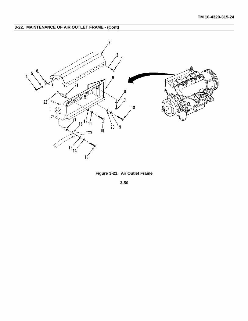
TM 10-4320-315-24
3-22. MAINTENANCE OF AIR OUTLET FRAME - (Cont)
Figure 3-21. Air Outlet Frame
3-50

TM10-4320-315-24
3-23. MAINTENANCE OF INTAKE AND EXHAUST MANIFOLDS
This task covers: a. Remove b. Install
INITIAL SETUP:
Tools General Safetv Instructions
General Mechanics Tool Kit(Item 1, Appendix B) WARNING
Materials/Parts •Solvent may cause toxic fumes. To preventpersonal injury, work only in well-ventilated area.
Rags (Item 12, Appendix C) DO NOT breath fumes for a long time.Cleaning Solvent (Item 19, Appendix C)Hose Clamps F(M 10-4320-315-24P) •Solvent is flammable. To prevent fire orCompression Rings (TM 10-4320-315-24P) explosion, DO NOT bring open flame or sparks
near solvent.
Equipment Conditions
Turbocharger removed (para. 3-21).Air outlet frame removed (para. 3-22).
a. REMOVE. (Figure 3-22)
(1) Remove nuts (1) and flat washers (2) holding the intake and exhaust manifolds (3 and 4) to the cylinder heads. Remove both manifolds together.
(2) Loosen hose clamps (5) at rubber sleeve (6) and separate intake manifold sections (7 and 8).
(3) Separate exhaust manifold sections (9 and 10). Remove compression rings (11).
(4) Remove gaskets (12 and 13).
b. INSTALL.
(1) Clean gasket surfaces on both intake and exhaust manifolds (3 and 4) with cleaning solvent, stiff brush, and rags.
(2) Position compression rings (11) and connect exhaust manifold sections (9 and 10).
(3) Connect intake manifold sections (7 and 8) with rubber sleeve (6) and hose clamps (5).
(4) Install gaskets (12 and 13) on cylinder heads studs (14 and 15).
(5) Install both intake and exhaust manifolds (3 and 4) together on the cylinder heads. Secure with 24 flat washers (2) and nuts (1).
3-51

TM 10-4320-315-24
3-23. MAINTENANCE OF INTAKE AND EXHAUST MANIFOLDS - (Cont)
Figure 3-22. Intake and Exhaust Manifolds
3-52

TM10-4320-315-24
3-24. MAINTENANCE OF AIR COWLING AND OIL COOLER DISCHARGE DUCT
This task covers: a. Remove b. Install
INITIAL SETUP:
Tools Equipment Conditions
General Mechanics Tool Kit Engine and pump assembly removed (para. 3-17).(Item 1, Appendix B) Fuel injector lines removed (para. 2-50).
Oil breather assembly removed (para. 2-48).Materials/Parts Oil inlet tube assembly removed (para. 2-45).
Oil cooler removed (para. 2-47).Lockwashers (TM 10-4320-315-24P) Cooling blower removed (para. 2-42).Tie Straps (Item 20, Appendix C)
a. REMOVE. (Figure 3-23)
(1) Disconnect wire lead (2) from No. 1 cylinder head assembly by removing screw (1).
(2) Remove bolts (3), lockwashers (4), and flat washers (5).
(3) Remove nut (6), lockwasher (7), flat washer (8), and bolt (9).
(4) Remove bolt (10), lockwasher (11), flat washer (12), and air duct wall (13).
(5) Remove wire (2) and grommet (14) from air duct wall (13).
(6) Cut and remove tie-wrap (15) that secures wire (16) of V-belt warning switch.
(7) Remove bolts (17), lockwashers (18), and flat washers (19).
(8) Remove bolt (20), lockwasher (21), and air duct wall (22).
(9) Remove bolts (23), flat washers (24), and oil cooler discharge duct (25).
(10) Remove bolts (26), lockwashers (27), flat washers (28), and lower cowling base (29).
(11) Remove bolts (30), lockwashers (31), flat washers (32), and clamps (33) that secure turbocharger air inlet tube.
(12) Remove bolts (39), lockwashers (35), flat washers (36), and cooling air baffle (37).
b. INSTALL
(1) Install cooling air baffle (37) with flat washers (36), lockwashers (35), and bolts (34).
(2) Install clamps (33) that secure turbocharger air inlet tube with flat washers (32), lockwashers (31), and bolts (30).
(3) Install lower cowling base (29) with flat washers (28), lockwashers (27), and bolts (26).
(4) Install oil cooler discharge duct (25), with flat washers (24) and bolts (23).
3-53

TM 10-4320-315-24
3-24. MAINTENANCE OF AIR COWLING AND OIL COOLER DISCHARGE DUCT - (Cont)
Figure 3-23. Air Cowling and Oil Cooler Discharge Duct
3-54

TM 10-4320-315-24
3-24. MAINTENANCE OF AIR COWLING AND OIL COOLER DISCHARGE DUCT - (Cont)
(5) Install air duct wall (22) with flat washers (18), lockwashers (18), and bolts (17). Install lockwasher (21) and bolt (20).
(6) Install tie straps (15) and secure wire (16) of V-belt warning switch.
(7) Install grommet (14) in cutout of air duct wall (13). Route wire (2) through grommet (14).
(8) Install air duct wall (13) with flat washer (12), lockwasher (11), and bolt (10). Install flat washer (8), bolt (9), lockwasher (7), and nut (6). Install flat washers (5), lockwashers (4), and bolts (3).
(9) Connect wire lead (2) on No. 1 cylinder head assembly with screw (1).
3-55

TM10-4320-315-24
3-25. MAINTENANCE OF FLYWHEEL
This task covers: a. Remove b. Install
INITIAL SETUP:
Tools Equipment Conditions
General Mechanics Tool Kit Pump disconnected from engine (para. 3-17).(Item 1, Appendix B)
Angle-of-Turn Indicator(Item 4, Appendix B)
a. REMOVE. (Figure 3-24)
(1) Remove flywheel bolts (1) and flywheel (2).
(2) Inspect flywheel (2) and ring gear (3) for cracks and damage.
Figure 3-24. Flywheel
b. INSTALL
(1) Install flywheel (2) on crankshaft (4) with ten flywheel bolts (1).
(2) Torque flywheel bolts (1) to 22 ft•lbs (29.8 N•m).
(3) Using angle-of-turn indicator, tighten flywheel bolts (1) 30°.
(4) Tighten flywheel bolts (1) an additional 30°.
3-56

TM10-4320-315-24
3-26. MAINTENANCE OF FLYWHEEL HOUSING
This task covers: a. INSERT FUNCTION b. INSERT FUNCTION c. INSERT FUNCTION
INITIAL SETUP:
ToolsEquipment Conditions
General Mechanics Tool Kit(Item 1, Appendix B) Flywheel removed (para. 3-25).
Materials/Parts
Lockwashers
a. REMOVE. (Figure 3-25)
(1) Remove bolt (1) and lockwasher (2) from outside of flywheel housing (5).
(2) Remove bolts (3), lockwashers (4) and flywheel housing (5).
b. INSTALL.
(1) Install flywheel housing (5) with lockwashers (4) and bolts (3).
(2) Install lockwasher (2) and bolt (1) on inside of flywheel housing (5).
Figure 3-25. Flywheel Housing
3-57
TM10-4320-315-24
3-27. MAINTENANCE OF CRANKSHAFT PULLEY AND DAMPER
This task covers: a. Remove b. Inspect c. Install
INITIAL SETUP:
Tools Equipment Conditions
General Mechanics Tool Kit V-belts removed (para. 2-41).(Item 1, Appendix B) Engine removed from pumping assembly
Angle-of-Turn Indicator (para. 3-17).(Item 4, Appendix B)
Retainer Tool(Item 19, Appendix B)
Multiplier Tool(Item 3, Appendix B)
Wrench, Torque(Item 3, Appendix B)
Materials/Parts
Grease (Item 8, Appendix C)Oil (Item 10, Appendix C)
a. REMOVE. (Figure 3-26)
NOTEBolt is left-hand threaded.
(1) Using retainer tool (1), hold crankshaft pulley (2) stationary.
(2) Turn pulley bolt (3) to the right. Remove bolt (3) and flat washer (4).
(3) Remove crankshaft pulley (2).
(4) Remove pulley mounting screws (5) and flat washers (6).
(5) Remove pulley (2) from damper (7).
b. INSPECT
(1) Inspect pulley (2) for cracks and chips. Replace defective pulley.
(2) Inspect damper shaft for worn or scored surface where engine front sealing ring contacts shaft. Replace worn or scored damper (7).
(3) Inspect damper (7) for cracks and chips. Replace defective damper (7).
3-58

TM 10-4320-315-24
3-27. MAINTENANCE OF CRANKSHAFT PULLEY AND DAMPER - (Cont)
Figure 3-26. Crankshaft Pulley and Damper
c. INSTALL.
(1) Position pulley (2) on damper (7).
(2) Install flat washers (6) and pulley mounting screws (5).
(3) Measure gap between pulley (2) and damper (7). Gap must be 1 in. (25.4 mm) or less.
(4) Lightly coat damper shaft and front seal with grease.
(5) Align index hole in pulley shaft with index pin on crankshaft gear. Slide damper (7) into position.
(6) Lightly coat pulley bolt (3) threads with oil. Install bolt (3) on pulley (2).
(7) Using retainer (1), hold pulley (2) stationary.
(8) Turn pulley bolt (3) to the left and tighten. Torque bolt to 30 ft•lbs (40 N•m).
(9) Using angle-of-turn indicator, tighten bolt 210°.
3-59
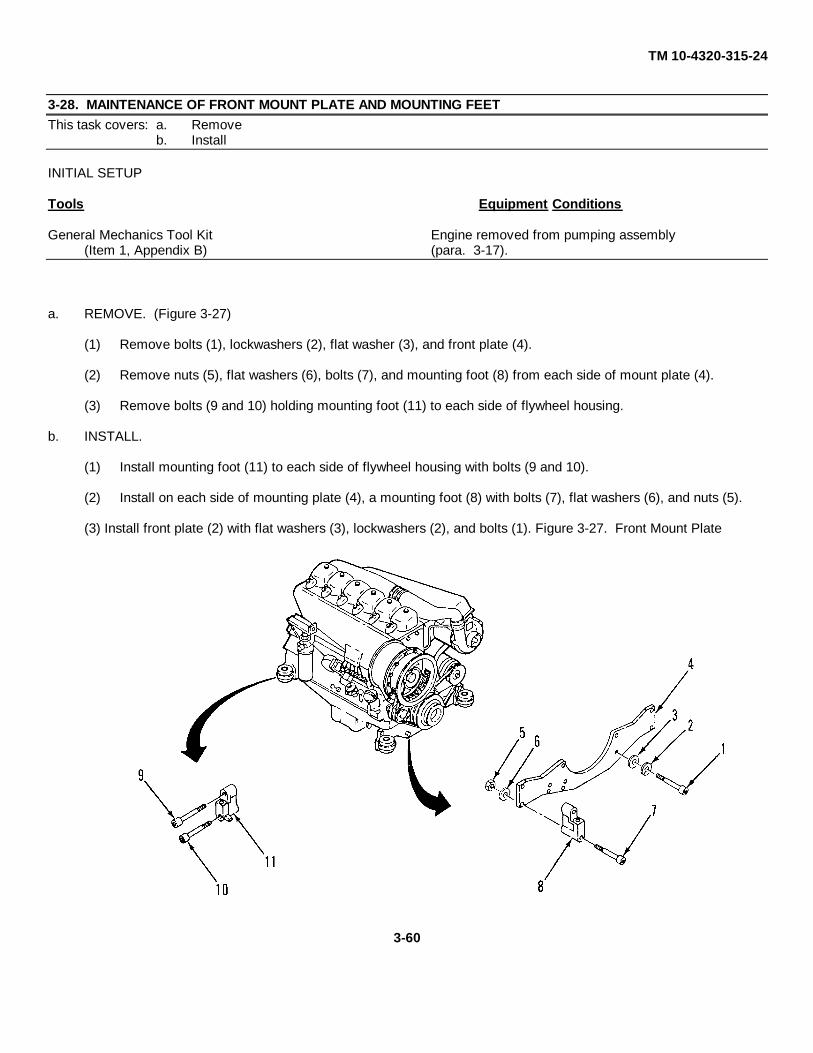
TM 10-4320-315-24
3-28. MAINTENANCE OF FRONT MOUNT PLATE AND MOUNTING FEETThis task covers: a. Remove
b. Install
INITIAL SETUP
Tools Equipment Conditions
General Mechanics Tool Kit Engine removed from pumping assembly(Item 1, Appendix B) (para. 3-17).
a. REMOVE. (Figure 3-27)
(1) Remove bolts (1), lockwashers (2), flat washer (3), and front plate (4).
(2) Remove nuts (5), flat washers (6), bolts (7), and mounting foot (8) from each side of mount plate (4).
(3) Remove bolts (9 and 10) holding mounting foot (11) to each side of flywheel housing.
b. INSTALL.
(1) Install mounting foot (11) to each side of flywheel housing with bolts (9 and 10).
(2) Install on each side of mounting plate (4), a mounting foot (8) with bolts (7), flat washers (6), and nuts (5).
(3) Install front plate (2) with flat washers (3), lockwashers (2), and bolts (1). Figure 3-27. Front Mount Plate
3-60

TM 10-4320-315-24
3-29. MAINTENANCE OF ROCKER ARM ASSEMBLY
This task covers: a. Remove c. Inspect/Repair e. Installb. Disassemble d. Assemble
INITIAL SETUP
Tools Equipment Conditions
General Mechanics Tool Kit Cylinder head cover removed (para. 2-54).(Item 1, Appendix B) Engine removed from pumping assembly (para. 3-
17).
a. REMOVE. (Figure 3-28)
Figure 3-28. Rocker Arm Assembly
3-61

TM 10-4320-315-24
3-29. MAINTENANCE OF ROCKER ARM ASSEMBLY - (Cont)
(1) Remove nuts (1) from rocker arm mounting studs (2).
(2) Remove rocker arm assembly.
NOTE These procedures apply to both rocker arms.
b. DISASSEMBLE.
(1) Remove circlip (3), flat washer (4), and rocker arm (5) from rocker arm bracket (6).
(2) Remove nut (7) and adjusting screw (8) from rocker arm (5).
(3) Remove nut (9) and oil nozzle (10).
c. INSPECT/REPAIR.
(1) Inspect thrust pad for wear and pitting. If worn or pitted, press out thrust pad (11) from rocker arm (5).
(2) Inspect adjusting screw (8) for damage threads and pitting at pushrod end. If damaged threads or pitted,replace adjusting screw (8).
(3) Inspect oil nozzle adjustment.
d. ASSEMBLE.
(1) Install adjusting screw (8) into rocker arm (5).
(2) Install rocker arm (5) on rocker arm bracket (6) with flat washer (4) and circlip (3).
(3) Install oil nozzle (10) into rocker arm (5) until it barely touches rocker arm bracket (6). Then back offslightly and lock in place with nut (9).
e. INSTALL.
(1) Place rocker arm assembly over rocker arm mounting studs (2) on cylinder head.
(2) Install nuts (1) on rocker arm mounting studs. Torque to 20.5 ft•lbs (28 N•m).
3-62

TM 10-4320-315-24
3-30. MAINTENANCE OF CYLINDER HEADS
This task covers: a. Removeb. Install
INITIAL SETUP
Tools Equipment Conditions
General Mechanics Tool Kit Electrical wire from temperature sensor disconnected(Item 1, Appendix B) (para. 2-37).Angle-of-Turn Indicator Fuel injectors removed (para. 2-50).(Item 4, Appendix B) Cylinder head cover removed (para. 2-54).Intake and exhaust manifolds removed (para. 3-23).Materials/Parts Front and end walls of cowling assembly removed
(para. 3-24).Tags (Item 21, Appendix C) Rocker arms removed (para. 3-29).60/40 Solder Lead Wire (Item 18, Appendix C)Grease (Item 8, Appendix C)
a. REMOVE. (Figure 3-29)
NOTE
To prevent malfunction of parts, reinstall pushrods in same location from which theywere removed.
(1) Tag and remove pushrods (1).
(2) Using square recess socket, remove two plugs (2) and seals (3) from cylinder head.
NOTE
Loosen head bolts in a diagonal sequence.
(3) Loosen head bolts (4) in stages.
(4) Depress spring (7) on each pushrod tube (6) to remove pushrod tubes from cylinder head (11). Removeand tag pushrod tubes.
(5) Remove springs (7), profile washers (8), and seals (9) from pushrod tubes (6).
(6) Remove cylinder head (11) with head bolts (4) and washers (5). Put location tag on cylinder.
(7) Remove cylinder head gasket (10).
3-63

TM 10-4320-315-24
3-30. MAINTENANCE OF CYLINDER HEADS - (Cont)
Figure 3-29. Cylinder Head
b. INSTALL.
(1) Install new head gasket (10) with sharp edge up.
(2) Install cylinder head (11).
(3) Check and adjust piston clearance (Figure 3-30):NOTE
Checking and adjusting piston clearance is required if either the cylinder, piston, or cylinderhead has been replaced.
3-64

TM 10-4320-315-24
3-30. MAINTENANCE OF CYLINDER HEADS - (Cont)
Figure 3-30. Checking Piston Clearance
(a) Apply grease to a 0.08 in. (2.032 mm) thick piece of lead wire.
(b) Lay lead wire on crown of piston.
(c) Position piston below Top Dead Center (TDC).
(d) Install cylinder head with head gasket on cylinder (11, Figure 3-24).
(e) Install four head bolts (4) with washers (5).
NOTE
Head bolts are tightened in diagonal sequence.
(f) Torque head bolts (4) to 22 ft•lbs (30 N•m).
(g) Using angle-of-turn indicator, tighten head bolts (5) 45°.
(h) Rotate crankshaft one complete turn.
(i) Remove cylinder head (11) with head bolts (4) and washers (5).
(a) Remove lead wire from top of piston.3-65

TM 10-4320-315-24
3-30. MAINTENANCE OF CYLINDER HEADS - (Cont)
(k) Measure lead wire at its thinnest point. Correct measurement is 0.039 - 0.047 in. (0.991 - 1.194 mm).
(I) If clearance was less than correct measurement, refer to general support maintenance to remove cylinder and add shims. If clearance was greater than correct measurement, refer to general support maintenance to remove cylinder and remove shims.
(4) Measure length of cylinder head bolts (4). If head bolts exceed 8.37 in. (212.6 mm), replace head bolt.
(5) Mount cylinder head (11) on engine.
(6) Align the cylinders.
(7) Install two alternating head bolts (4) with washers (5).
(8) Without changing cylinder alignment, align intake and exhaust flanges.
(9) Install other two head bolts (4) and washers (5).
NOTE
Head bolts are tightened in diagonal sequence.
(10) Torque head bolts (4) to 22 ft•lbs (29.8 N•m) ensuring head remains in alignment.
(11) Using angle-of-turn indicator, tighten head bolts (4) 450°.
(12) Using angle-of-turn indicator, again tighten head bolts 450 for a second and third time.
(13) Tighten head bolts (4) 30°.
(14) Install new seals (3) on plugs (2).
(15) Install plug (2) in cylinder head (11). Torque plugs 50 - 66 ft•lbs (67.8 - 89.5 N•m).
(16) Using pushrod spring compressor, assemble spring (7) on pushrod tube (6).
(17) Install profile washer (8) on bottom end of pushrod tube (6), dome side toward spring.
(18) Install new sealing ring (9) on bottom end of pushrod tube, flat side toward end of tube.
(19) Install new sealing ring (9) over top of pushrod tube, flat side toward tube shoulder.
(20) Insert spring end of pushrod tubes (6) in crankcase pushrod holes.
(21) Align top end of pushrod tubes (6) with cylinder head cones.
(22) Remove spring tensioning tool.
(23) Remove tags and install pushrod tubes (6).
(24) Remove tags and install pushrods (1).3-66

TM 10-4320-315-24
3-31. MAINTENANCE OF PUMP SUCTION LINE
This task covers: a. Removeb. Install
INITIAL SETUP
Tools Equipment Conditions
General Mechanics Tool Kit Noise enclosure rear panels removed (para. 3-8).(Item 1, Appendix B)
a. REMOVE. (Figure 3-31)
(1) Remove nuts (1), lockwashers (2), and bolts (3).
(2) Remove suction line nipple (4).
(3) Remove gasket (5).
(4) Remove nuts (6) and lockwashers (7).
(5) Remove suction line elbow (8).
(6) Remove gasket (9).
b. INSTALL.
(1) Clean mating surfaces.
(2) Install gasket (9).
(3) Install suction line elbow (9) and secure with lockwashers (7) and nuts (6).
(4) Install gasket (5).
(5) Install suction line nipple (4). Secure with bolts (3), lockwashers (2) and nuts (1).
3-67

TM 10-4320-315-24
3-31. MAINTENANCE OF PUMP SUCTION LINE - (Cont)
Figure 3-31. Pump Suction Line.
3-68

TM 10-4320-315-24
3-32. MAINTENANCE OF PUMP DISCHARGE LINE
This task covers: a. Removeb. Install
INITIAL SETUP
Tools Equipment Conditions
General Mechanics Tool Kit Noise enclosure rear panels removed (para. 3-8).(Item 1, Appendix B)
a. REMOVE. (Figure 3-32)
(1) Remove nuts (1), lockwashers (2) and bolts (3).
(2) Remove discharge line nipple (4).
(3) Remove gasket (5).
(4) Remove nuts (6) and lockwashers (7).
(5) Remove discharge line elbow (8) and gasket (9).
b. INSTALL.
(1) Clean mating surfaces.
(2) Install gasket (9).
(3) Install discharge line elbow (8). Secure with lockwashers (7) and nuts (6).
(4) Install gasket (5).
(5) Install discharge line nipple (4). Secure with bolts (3), lockwashers (2) and nuts (1).
3-69

TM 10-4320-315-24
3-32. MAINTENANCE OF PUMP DISCHARGE LINE - (Cont)
Figure 3-32. Pump Discharge Line
3-70

TM 10-4320-315-24
3-33. MAINTENANCE OF PUMP
This task covers: a. Disassemble c. Repairb. Inspect d. Assemble
INITIAL SETUP
Tools Equipment Conditions
General Mechanics Tool Kit Pump is removed from pumping assembly (para. 3-(Item 1, Appendix B) 17).Gear Puller(Item 3, Appendix B)
Materials/Parts
Lockwashers (TM 10-4320-315-24P)
a. DISASSFMBLE.
(1) Remove flex coupling from pump shaft as follows (Figure 3-33):
Figure 3-33. Flex Coupling3-71

TM 10-4320-315-24
3-33. MAINTENANCE OF PUMP - (Cont)
(a) Remove socket head screws (1) that secure outer rubber flex (2) to inner steel hub (3).
(b) Remove outer rubber flex (2) from inner steel hub (3).
(c) Loosen setscrew (4) that secures inner steel hub (3) to pump shaft (5).
(d) Using gear puller, remove inner steel hub (3) from pump shaft (5).
(e) Remove key (6) from pump shaft (5).
(2) Disassemble pump as follows (Figure 3-34):
NOTE
Although this procedure provides complete disassembly and assembly instructions,disassemble pump only as necessary to replace defective components.
(a) Remove nuts (1) and lockwashers (2).
(b) Remove bearing housing (3) from pump body (4).(c) Remove gasket (5).
Figure 3-34. Pump3-72

TM 10-4320-315-24
3-33. MAINTENANCE OF PUMP - (Cont)
CAUTION
Do not insert metal objects in vanes.
NOTE
Impeller has right hand threads.
(d) Unscrew and remove Impeller (6) from impeller shaft (13).
(e) Remove spring (7) and shaft seal assembly (8) with O-ring (9).
(f) Inspect wear ring (10). If worn, remove wear ring.
(g) Remove retaining rings (11) and (12).
(h) Using hydraulic press on flywheel end of shaft, press impeller shaft (13) slowly out of bearinghousing (3).
(i) Remove wear ring/seal (14) as shaft moves it out of bearing housing (3). Remove seal (15).
(j) Remove slinger (16).
(k) Remove O-ring (17).
(I) Inspect shaft sleeve (18). If worn, remove shaft sleeve.
(m) Remove seal (19) with O-ring (20).
(n) Using hydraulic press, remove bearing (21) from impeller shaft (13).
(o) Remove retaining rings (22 and 23) and bearing (24) from bearing housing (3).
b. INSPECT.
(1) Wash all components except seal assembly in cleaning solvent.
(2) Inspect metal parts for stripped/damaged threads, cracks, chips and weld damage.
(3) Inspect bearings for smooth operation.
c. REPAIR,
Repair is accomplished by replacement of parts.
d. ASSEMBLE
(1) Assemble pump as follows (Figure 3-34):
(a) Install retaining ring (22) and bearing (24) into bearing housing (3).3-73

TM 10-4320-315-24
3-33. MAINTENANCE OF PUMP - (Cont)
(b) Using hydraulic press, install bearing (21) on impeller shaft (13).
(c) Install seal (19) with O-ring (20).
(d) If removed, install shaft sleeve (18).
(e) Install O-ring (17).
(f) Install slinger (15).
(g) Install seal (15) on wear ring/seal (14).
(h) Install wear ring/seal (14).
(i) Install retaining ring (12).
(j) Using hydraulic press, install impeller shaft (13) (with assembled parts) into bearing housing (3).
(k) Install retaining rings (11 and 23).
(I) If removed, install wear ring (10).
(m) Install shaft seal assembly (8) with O-ring (9).
(n) Install spring (7).
(o) Install impeller (6) on impeller shaft (13).
(p) Install gasket (5) on pump body (4).
(q) Install bearing housing (3) on pump body (4). Secure with lockwashers (2) and nuts (1).
(2) Install flex coupling as follows:
(a) Loosen socket head screws (7) that secure outer rubber flex (8) with inner steel hub (9).
(b) Remove outer rubber flex (8) from inner steel hub (9).
(c) Install key (12) onto pump shaft (11).
(d) Position inner steel hub (9) on pump shaft (11) (chamfered edge towards pump) and key (12) flushwith end of shaft.
(e) Secure inner steel hub (9) onto pump shaft (11) by tightening setscrew (10).
(f) Place outer rubber flex (8) over inner steel hub (9) (pin-stud holes with extended bosses towards flywheel). Provide for a clearance of 0.059 +0.0197 in. (1.5 +0.5 mm) between outer rubber flex(8) and engine flywheel and secure by tightening socket head screws (7).
3-74
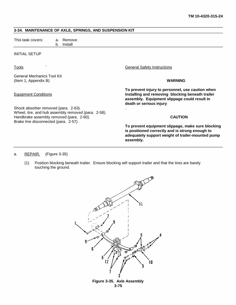
TM 10-4320-315-24
3-34. MAINTENANCE OF AXLE, SPRINGS, AND SUSPENSION KIT
This task covers: a. Removeb. Install
INITIAL SETUP
Tools ` General Safety Instructions
General Mechanics Tool Kit(Item 1, Appendix B) WARNING
To prevent injury to personnel, use caution whenEquipment Conditions installing and removing blocking beneath trailer
assembly. Equipment slippage could result in death or serious injury
Shock absorber removed (para. 2-63). .Wheel, tire, and hub assembly removed (para. 2-58).Handbrake assembly removed (para. 2-60). CAUTIONBrake line disconnected (para. 2-57).
To prevent equipment slippage, make sure blockingis positioned correctly and is strong enough toadequately support weight of trailer-mounted pumpassembly.
a. REPAIR. (Figure 3-35)
(1) Position blocking beneath trailer. Ensure blocking will support trailer and that the tires are barelytouching the ground.
Figure 3-35. Axle Assembly3-75
TM 10-4320-315-24
3-34. MAINTENANCE OF AXLE, SPRINGS, AND SUSPENSION KIT - (Cont)
(2) Remove front spring mounting bolt (1) and nut (2) from each spring assembly (6).
(3) Remove rear spring mounting bolts (3 and 4) and shackle plates (5) from each spring assembly (6).
(4) Remove the spring assembly (6) by loosening and removing the four nuts (7) and spring clamp (12) onthe two U-bolts (8) at each end of the axle (11).
(5) Remove nylon bushings (9) from both ends of each spring and two rear hangers (10).
b. INSTALL.
(1) Install new nylon bushings (9) in both ends of each spring and two rear hangers (10).
(2) Install shackle plates (5) on each side of trailer chassis.
NOTE
Do not tighten shackle plate mounting bolts against nuts until after installing spring assemblieson trailer chassis. Shackle plates may have to be repositioned to allow for spring installation.
(3) Install mounting bolt (3) and nut (4) through each set of shackle plates (5).
(4) Align spring assemblies (6) for installation on each side of trailer chassis.
(5) Install spring mounting bolts (1) and nut (2) on both ends of each spring assembly. Tighten bolts (1 and 3) against nuts (2 and 4) until spring assemblies are secured to trailer chassis and shackle plates (5).
(6) Tighten mounting bolts (3) on each set of shackle plates (5).
(7) Install axle (11) on spring assemblies beneath trailer chassis.
(8) Install spring clamp (12), two U-bolts, four washers and four nuts on each spring assembly.
3-76

TM 10-4320-315-24
3-35. MAINTENANCE OF SAFETY CHAINS
This task covers: a. Remove c. Installb. Repair
INITIAL SETUP
Tools References
Welding Trailer TM 9-237NSN 4940-00-357-7268
PartslMaterials
Cotter Pin (Item 11, Appendix C)
a. REMOVE. (Figure 3-36)
(1) Using torch, cut weld holding chain link (1) to trailer chassis (2).
(2) Remove safety chain (3).
Figure 3-36. Safety Chains
3-77
TM 104320-315-24
3-35. MAINTENANCE OF SAFETY CHAINS - (Cont)
b. REPAIR.
(1) Remove cotter pin (4), pin (5), and hook (6) from chain link (7).
(2) Repair or replace chain (2) as required.
(3) Install hook (6) on end link (7) with pin (5) and cotter pin (4).
c. REPLACE.
(1) Install safety chain (3) on bracket.
(2) Weld chain link (1) to trailer chassis (2) in accordance with TM 9-237.
3-78

TM 10-4320-315-24CHAPTER 4
GENERAL SUPPORT MAINTENANCE INSTRUCTIONS
Section I. REPAIR PARTS, SPECIAL TOOLS, TMDEAND SUPPORT EQUIPMENT
PARAGRAPH TITLE PARAGRAPH
General ........................................................................................................................................................................ 4-1
4-1. General. Repair parts are listed and illustrated in TM 10-4320-315-24P. No special tools are required for generalsupport maintenance of the pumping assembly. Test, Maintenance and Diagnostic Equipment (TMDE) and supportequipment includes standard test equipment found in any general support maintenance facility.
Section II. MAINTENANCE PROCEDURES
4-2. Introduction . This section contains instructions covering maintenance functions for the general support level onthe pumping assembly.
PARAGRAPH TITLE PARAGRAPH
Camshaft Tappets ...................................................................................................................................................... 4-14Connecting Rods .......................................................................................................................................................... 4-9Crankcase .................................................................................................................................................................. 4-15Crankcase Front Cover .............................................................................................................................................. 4-10Crankcase Rear Cover ............................................................................................................................................... 4-12Crankshaft ................................................................................................................................................................. 4-13Cylinder Heads ............................................................................................................................................................. 4-4Cylinder Liners ............................................................................................................................................................. 4-5Fuel Injectors ............................................................................................................................................................... 4-3Introduction .................................................................................................................................................................. 4-2Oil Pan and Baffle Plate ............................................................................................................................................... 4-7Oil Pump and Oil Discharge Pipe ............................................................................................................................... 4-11Oil Pump Suction Tube ................................................................................................................................................ 4-8Pistons ......................................................................................................................................................................... 4-6
4-1

TM10-4320-315-24
4-3. MAINTENANCE OF FUEL INJECTORS
This task covers: a. Disassembly c. Assemblyb. Repair d. Test
INITIAL SETUP:
Tools General Safety Instructions
General Mechanics Tool KitItem 1, Appendix B) WARNING
Materials/Parts Diesel fuel is flammable. Keep sparks, cigarettes,and open flame away from fuel system components
Fuel (Item 9, Appendix C) while working on engine.
Equipment Conditions
Fuel injectors removed (para. 2-50).
a. DISASSEMBLE. (Figure 4-1)
(1) Remove injection cap (1) from nozzle holder (2).
(2) Remove nozzle assembly (3), intermediate piece (4), plunger (5), spring (6), and shims (7).
b. INSPECT.
(1) Wash all parts with clean diesel fuel.
(2) Inspect intermediate piece for scratches, burrs, or wear on the seating surfaces. Replace damaged intermediate piece.
CAUTION
Do not touch needle seating surface. Needle can be damaged.
(3) Remove needle (8) from nozzle assembly (3).
(4) Insert needle (8) into nozzle assembly (3). Hold nozzle assembly vertical. Allow needle (8) to slide slowly, under its own weight, down on seat. If needle does not seat, replace nozzle assembly.
c. ASSEMBLE.
(1) Insert shims (7) in the nozzle holder (2).
(2) Refer to injector test (task d). Add or subtract shims (8) as necessary to obtain correct opening pressure.
(3) Insert spring (6) in nozzle holder (2).
(4) Install plunger (5) on spring (6) with beveled side of plunger away from spring.4-2

TM 10-4320-315-24
4-3. MAINTENANCE OF FUEL IN JECTORS - (Cont)
Figure 4-1. Fuel Injector
(5) Install intermediate piece (4) on nozzle holder (2). Guide pins (9) on intermediate piece into holes on nozzle holder.
(6) Install nozzle assembly (3) on intermediate piece (4). Guide pins (10) on intermediate piece into holes on nozzle.
(7) Install Injector cap on nozzle holder.
4-3

TM 10-4320-315-24
4-3. MAINTENANCE OF FUEL INJECTORS - (Cont)
d. TEST,
(1) Connect fuel injector to injection test set.
WARNING
• Do not put hands under nozzle during test. Fuel under high pressure can cause severe injury.
• Diesel fuel is flammable. Keep sparks, cigarettes, and open flame away from fuel systemcomponents while working on engine.
NOTE
Adding shims will increase nozzle opening pressure. Removing shims will decrease nozzlepressure.
(2) Pump injection test set until fuel sprays from tip of nozzle. Note reading on pressure gage. Gage reading must be 2538-2654 psi (17497-18297 kPa).
(3) Pump injection test set until fuel sprays from tip of nozzle. Check pattern of fuel spray. Fuel must spray in a mist from jets. Presence of a solid stream indicates a faulty nozzle.
(4) Pump injection test set until pressure gage reads 2102-2175 psi (14491-14994 kPa). Hold pressure for30 seconds. If fuel leaks from nozzle tip, nozzle is faulty.
(5) Bleed pressure from injection test set. Remove fuel injector.
4-4

TM10-4320-315-24
4-4. MAINTENANCE OF CYLINDER HEADS
This task covers: a. Disassemble c. Repairb. Inspect d. Assemble
INITIAL SETUP:
Tools General Safety Instructions
Compressor, Valve Spring(Item 3, Appendix B) WARNING
Gage, Depth, Dial Indicator(Item 3, Appendix B) Hot cylinder head can cause severe burns. Wear
heat resistance gloves.Materials/Parts
Equipment ConditionsTags (Item 21, Appendix C)Gloves (Item 6, Appendix C) Cylinder head removed (para. 3-30).
a. DISASSEMBLE.
(1) Using valve spring compressor, remove valves and valve springs (Figure 4-2).
(a) Compress valve spring (1) and remove valve cones (2).
Figure 4-2. Valves and Valve Springs
4-5
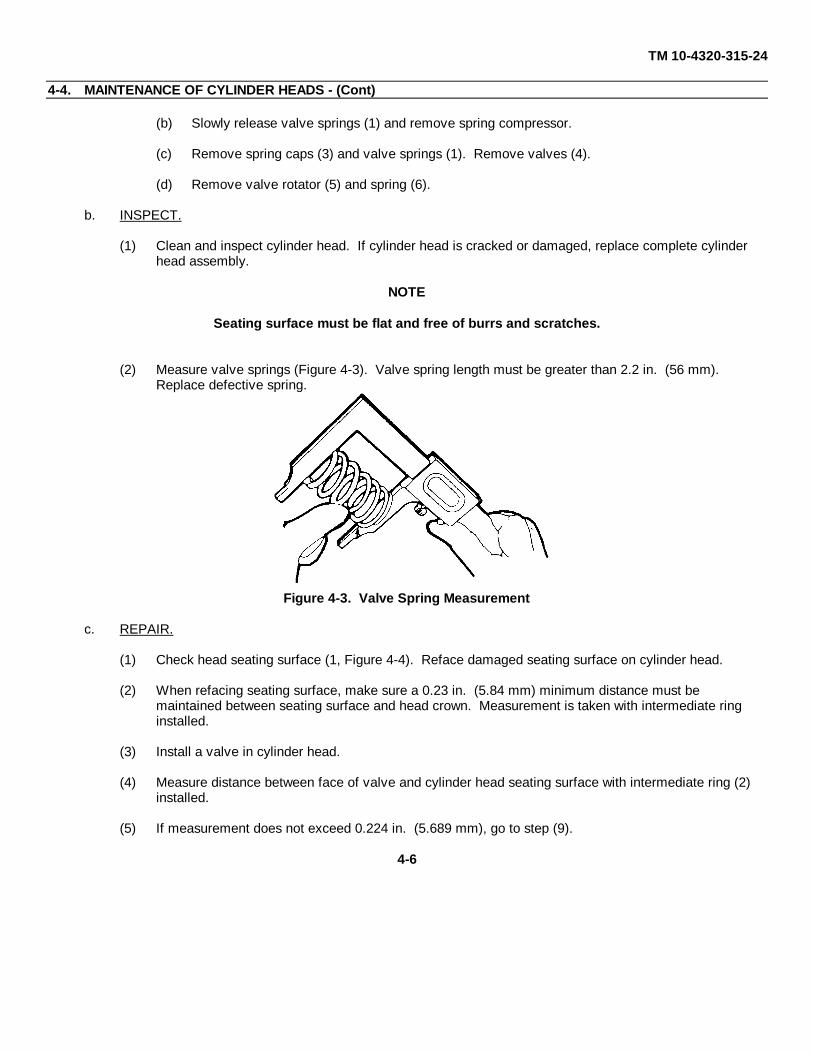
TM 10-4320-315-24
4-4. MAINTENANCE OF CYLINDER HEADS - (Cont)
(b) Slowly release valve springs (1) and remove spring compressor.
(c) Remove spring caps (3) and valve springs (1). Remove valves (4).
(d) Remove valve rotator (5) and spring (6).
b. INSPECT.
(1) Clean and inspect cylinder head. If cylinder head is cracked or damaged, replace complete cylinder head assembly.
NOTE
Seating surface must be flat and free of burrs and scratches.
(2) Measure valve springs (Figure 4-3). Valve spring length must be greater than 2.2 in. (56 mm). Replace defective spring.
Figure 4-3. Valve Spring Measurement
c. REPAIR.
(1) Check head seating surface (1, Figure 4-4). Reface damaged seating surface on cylinder head.
(2) When refacing seating surface, make sure a 0.23 in. (5.84 mm) minimum distance must be maintained between seating surface and head crown. Measurement is taken with intermediate ring installed.
(3) Install a valve in cylinder head.
(4) Measure distance between face of valve and cylinder head seating surface with intermediate ring (2) installed.
(5) If measurement does not exceed 0.224 in. (5.689 mm), go to step (9).
4-6

TM 10-4320-315-24
4-4. MAINTENANCE OF CYLINDER HEADS - (Cont)
Figure 4-4. Cylinder Head Measurement
(6) If measurement exceeds 0.224 in. (5.689 mm), drill out valve seats (3). Take care not to damage cylinder head.
WARNING
Hot cylinder head can cause severe burns. Wear heat resistance gloves.
(7) Heat cylinder head to 428°F (220°C).
(8) Seat new valve seats in cylinder head, chamfer side of valve seats up.
(9) Measure and record exhaust valve stem. Minimum diameter is 0.312-0.3128 in. (7.920-7.940 mm). Replace defective valve.
(10) Measure and record intake valve stem. Minimum diameter is 0.307-0.313 in. (7.810-7.960 mm). Replace defective valve.
NOTE
If valves are replaced, the corresponding valve guides must also be replaced.
(11) Measure and record the inside diameter of both valve guides.
(12) Subtract valve stem measurements from valve guide measurements to obtain valve stem clearance.
4-7

TM 10-4320-315-24
4-4. MAINTENANCE OF CYLINDER HEADS - (Cont)
(13) If clearance exceeds 0.0024-0.0037 in. (0.06-0.095 mm) for exhaust and 0.0016-0.0028 in. (0.04-0.07mm) for Intake, replace valve guide.
(14) Heat cylinder head to 428°F (220°C); drive out valve guide.
(15) Install new snap spring (6, Figure 4-1) on new valve guide (7).
(16) Insert long end of valve guide (7) into valve guide bore from top of cylinder head (8).
(17) Drive in valve guide (7) until snap spring (6) seats.
(18) Allow cylinder head to cool. Ream valve guide (Figure 4-5).
d. ASSEMBLE.
(1) Install valves (4) in cylinder head (8).
(2) Insert valve rotators (5) over valve stems of valves (4).
(3) Install springs (1) on valves (4). Close coils of springs toward rotator (5).
(4) Install spring caps (3) on springs (1).
(5) Compress valve springs (1), install valve cones (2).
Figure 4-5. Reaming Valve Guides
4-6

TM10-4320-315-24
4-5. MAINTENANCE OF CYLINDER LINERS
This task covers: a. Remove c. Installb. Inspect
INITIAL SETUP:
Tools Equipment Conditions
Ring Compressor Cylinder head removed (para. 3-30).(Item 3, Appendix B)
Inside and Outside Micrometer(Item 3, Appendix B)
Materials/Parts
Shims (TM 10-4320-315-24P)Oil, Lubricating
(Item 10, Appendix C)
a. REMOVE. (Figure 4-6)
(1) Set piston at Bottom Dead Center (BDC).
(2) Rotate crankshaft until piston lift cylinder out of crankcase.
(3) Slide cylinder off piston.
Figure 4-6. Cylinder Liner
4-9

TM 10-4320-315-24
4-5. MAINTENANCE OF CYLINDER LINERS - (Cont)
(4) Remove shims (1) from cylinder (2). Record thickness of shims.
b. INSPFCT,
CAUTION
To prevent malfunction of parts, piston must be replaced if new cylinder is being Installed.
(1) Inspect cylinder walls for scratches or other damage. Replace damaged cylinder.
(2) Check machined mating surface on top and bottom of cylinder. If surface is not smooth or is grooved pitted, replace cylinder.
(3) Measure cylinder bore at depth levels 1, 2, 3, and 4 (Figure 4-7).
Figure 4-7. Cylinder Measurement
NOTE
Measurements at all four levels must be made along center line a and cross-line b.
(4) Replace cylinder if any measurement exceeds 4.007 in. (101.78 mm).
(5) Inspect cylinder mating surface on crankcase for scratches or burrs. Reface damaged surface.
4-10

TM 10-4320-315-24
4-5. MAINTENANCE OF CYLINDER LINERS - (Cont)
c. INSTALL. (Figure 4-6)
NOTE
Shims must be at least equal in thickness to shims which were removed.
(1) Install shims (1) on cylinder (2) that are 0.2 mm more than thickness of shims removed.
(2) Coat piston, rings, and cylinder lightly with oil.
(3) Install piston ring gaps around piston at 10, 2, and 4 o'clock positions using wrist pin as 12 o'clock.
(4) Install two small wood blocks under piston to hold it erect.
(5) Install ring compressor on piston. Slide cylinder down piston until piston rings are inside cylinder.
(6) Remove ring compressor and wood blocks.
(7) Rotate cylinder until cutout side of cylinder is facing pushrod bores.
(8) Install cylinder on crankcase. Align cylinder with adjacent cylinders.
4-11

TM10-4320-315-24
4-6. MAINTENANCE O F PISTONS
This task covers: a. Remove c. Installb. Inspect
INITIAL SETUP:
Tools Equipment Conditions
General Mechanics Tool Kit Cylinder liner removed (para. 4-5).(Item 1, Appendix B)
Gage, Piston Keystone Groove(Item 10, Appendix B)
Materials/Parts
Tags (Item 21, Appendix C)
a. REMOVE.
(1) Remove piston pin circlips (1, Figure 4-8), piston pin (2), and piston (3) from connecting rod (4).
(2) Tag piston (3) to its cylinder order.
(3) Remove piston rings (5) from piston (3).
b. INSPECT.
NOTE
If piston is replaced, the piston pin, piston rings, and cylinder must also be replaced.
(1) Inspect piston and piston rings for cracks, chips, and burrs.
(2) Replace defective components.
(3) Clean ring grooves in piston.
(4) Use ring groove gage. Insert pin on gage into first ring groove of piston. If gage body touches piston, the piston is defective.
NOTE
If any of the clearances do not meet specifications, piston is defective.
4-12

TM 10-4320-315-24
4-6. MAINTENANCE OF PISTONS - (Cont)
(5) Measure groove width of second and third piston ring grooves. Correct clearances are:
• Second groove = 0.102-0.103 in. (5.90-2.61 mm).
• Third groove = 0.198-0.199 (5.030-5.050 mm).
Figure 4-8. Piston
(6) Insert ring into cylinder. Use piston to push ring down to a point approximately 1 in. (25.4 mm) from top of cylinder. Measure and record ring end gap. Remove ring.
(7) Repeat step (6) until all rings have been checked.
NOTE
If ring gaps do not meet specifications, piston rings are defective.
(8) Correct ring end gap. Clearances are:
• Trapezoidal compression ring = 0.012-0.018 in. (0.30-0.45 mm).
• Tapered compression rings = 0.008-0.018 in. (0.20-0.45 mm).
• Scraper ring = 0.050-0.016 in. (0.250-0.40 mm).
4-13

TM 10-4320-315-24
4-6. MAINTENANCE OF PISTONS - (Cont)
(9) Inspect piston pin bushing for burrs, worn spots, and discoloration.
(10) Measure piston pin at wear surfaces. Outer diameter of piston pin must go between 1.3787-1.379 in. (34.994-35.0 mm). If not replace, defective piston pin.
(11) Measure piston pin bore in piston. If bore measurement exceeds 1.379-1.3792 in. (35.0-35.006 mm) piston is defective and must be replaced.
c. INSTALL.
(1) Install piston rings (5) on piston (3) placing the gaps evenly spaced around piston.
(2) Insert one circlip (1) in groove in piston pin bore (6) with opening at 12 or 6 o'clock position.
(3) Install piston (3) on connecting rod (4), arrow on top of piston (3) pointing toward pushrod bores (7).
(4) Insert piston pin (2) into piston bore (6). Pin must contact circlip (1).
(5) Install second circlip (1) with opening at 12 or 6 o'clock position.
4-14

TM10-4320-315-24
4-7.MAINTENANCE OF OIL PAN AND BAFFLE PLATE
This task covers: a. Removeb. Install
INITIAL SETUP:
Tools General Safety Instructions
General Mechanics Tool Kit(Item 1, Appendix B) WARNING
Materials/Parts • Solvent may cause toxic fumes. To preventpersonal injury, work only in well-ventilated area.
Sealant (Silicone) DO NOT breath fumes for a long time.(Item 16, Appendix C)
Rags (Item 12, Appendix C) • Solvent is flammable. To prevent fire orCleaning Solvent explosion, DO NOT bring open flame or sparks
(Item 19, Appendix C) near solvent.
Equipment Conditions
Engine removed from pump (para. 3-17).
a. REMOVE. (Figure 4-9)
NOTE
• Note location of long screw and spacer for crankcase vent hose holder.
• Cutout of baffle plate is towards dipstick.
(1) Remove long screw (1), clamp (2), flat washers (3), and spacer (4).
(2) Remove oil pan mounting screws (5) and flat washers (6).
(3) Remove oil pan (7) and baffle (8).
(4) Clean mating surfaces.
b. INSTALL.
(1) Apply silicone to mating surfaces. Install baffle plate (8) and oil pan (7).
(2) Install flat washers (6) and oil pan mounting screws (5).
(3) Install spacer (4), flat washer (3), clamp (2) for oil breather hose, and long screw (1).
4-15
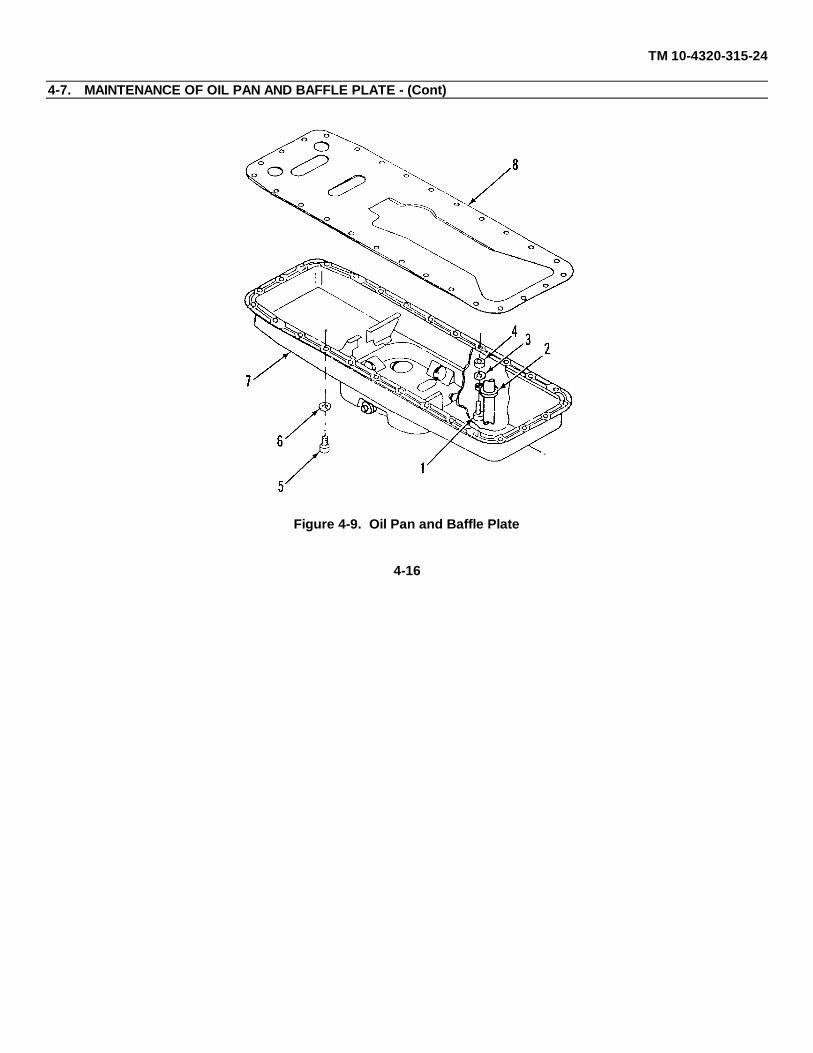
TM 10-4320-315-24
4-7. MAINTENANCE OF OIL PAN AND BAFFLE PLATE - (Cont)
Figure 4-9. Oil Pan and Baffle Plate
4-16

TM10-4320-315-24
4-8. MAINTENANCE OF OIL PUMP SUCTION TUBE
This task covers: a. Removeb. Install
INITIAL SETUP:
Tools Equipment Conditions
General Mechanics Tool Kit Oil pan and baffle plate removed (para. 4-7).(Item 1, Appendix B)
Materials/Parts
Lockwashers (TM 10-4320-315-24P)
a. REMOVE. (Figure 4-10)
(1) Remove mounting bolts (1) and lockwashers (2) holding the oil pump suction tube (3) to main bearing cap.
(2) Loosen the suction tube hex nut (4). Remove oil pump suction tube (3) with duplex ring (5).
(3) Remove nuts (6), star washers (7), bolts (8) and retaining bracket (9) from oil pump suction tube (3).
Figure 4-10. Oil Pump and Suction Tube
4-17

TM 10-4320-315-24
4-8. MAINTENANCE OF OIL PUMP SUCTION TUBE - (Cont)
b. INSTALL.
(1) Install retaining bracket (9) on oil pump suction tube (3) with bolt (8), star washer (7), and nut (6).
(2) Position suction tube hex nut (4) and duplex ring (5) on oil pump suction tube (3) and connect to oil pump (10).
(3) Secure retaining bracket (9) holding oil pump suction tube (3) to main bearing cap with lockwashers (2)and mounting bolts (1).
4-18

TM10-4320-315-24
4-9. MAINTENANCE OF CONNECTING RODS
This task covers: a. Remove c. Installb. Inspect
INITIAL SETUP:
Tools Equipment Conditions
General Mechanics Tool Kit Pistons removed (para. 4-6).(Item 1, Appendix B) Oil pan removed (para. 4-7).
Angle-of-Turn Indicator(Item 4, Appendix B)
Inside and Outside Micrometer(Item 3, Appendix B)
Bushing Insert Device Fixture(Item 11, Appendix B)
Materials/Parts
Oil, Lubricating(Item 10, Appendix C)
a. REMOVE. (Figure 4-11)
(1) Remove connecting rod capscrews (1).
CAUTION
Connecting rod, caps, and bearing shells are matched and must not be mixed. Bearings couldbe damaged.
(2) Remove rod caps (2) with bearing shells (3). Tag caps and bearing shells.
(3) Remove and tag connecting rod (4) and bearing shells (5).
b. INSPFCT.
(1) Check connecting rod for straightness and visible damage. Replace defective connecting rod.
(2) Using micrometer, measure inside diameter of piston pin bushing at points 1 and 2 in the planes of a and b. Correct measurement is 1.577-1.579 in. (40.040-40.084 mm).
(3) Remove any worn bushing (6, Figure 4-11) and press in new bushing. Make sure oil holes are aligned.
(4) Install rod cap (2) on connecting rod (4).
(5) Install connecting rod capscrews (1). Torque screws to 22 ft • lbs (29.8 N•m).
(6) Using angle-of-turn indicator, tighten rod capscrews 30°, then 60°.4-19

TM 10-4320-315-24
4-9. MAINTENANCE OF CONNECTING RODS - (Cont)
Figure 4-11. Connecting Rods
(7) Using micrometer, measure inside diameter of connecting rod bearing bore at points 1 and 2 in the planes of a and b (Figure 4-12). Correct measurement is 2.6792-2.6799 in. (68.0-68.019 mm).
(8) Replace a defective connecting rod.
(9) Remove connecting rod capscrews and cap.
(10) Check connecting rod bearing clearance as follows:
(a) Measure crankshaft journals. Correct measurement is 2.485-2.521 in. (63.071-63.990 mm).
(b) Install bearing shell (5, Figure 4-11) in bore of connecting rod (4).
(c) Install bearing shell (5) in rod cap (2).
(d) Install rod cap (2) on connecting rod (4) with capscrews (1).
(e) Torque capscrews to 22 ft • lbs (29.8 N•m).
4-20

TM 10-4320-315-24
4-9. MAINTENANCE OF CONNECTING RODS - (Cont)
Figure 4-12. Connecting Rod Measurements
(f) Using micrometer, measure inside diameter of connecting rod.
(g) Subtract reading in step (f) from reading in step (a) to determine bearing clearance.
(h) Replace bearing shells (5) or crankshaft if correct clearance (0.0059 in. (0.15 mm)) is not obtained.
(i) Remove connecting rod capscrews (1) and rod cap (2). Remove bearing shells (5).
c. INSTALL. (Figure 4-11)
(1) Install new bearing shell half (5) in bore of connecting rod (4).
(2) Lightly coat bearing shell (5) and crankshaft journal with oil.
(3) Install connecting rod (4) on crankshaft journal.
(4) Lightly coat crankshaft journal and other bearing shell half (3) with oil.
(5) Insert bearing shell (3) half in rod cap (2).
(6) Install rod cap (2) with new rod capscrews (1) on connecting rod (4).
(7) Torque rod capscrews to 2.216 ft. lbs (5.629 Nom).
(8) Using angle-of-turn indicator, tighten rod capscrews (1) 30°.
(9) Tighten rod capscrews (1) 60°.
4-21

TM 10-4320-315-24
4-10. MAINTENANCE OF CRANKCASE FRONT COVER
This task covers: a. Remove b. Install
INITIAL SETUP:
Tools Equipment Conditions
General Mechanics Tool Kit Alternator brackets removed (para. 2-52).(Item 1, Appendix B) Turbocharger removed (para. 3-21).
Assembly Device, Crankshaft Air cowling removed (para. 3-24).Seal (Item 12, Appendix B) Crankshaft pulley removed (para. 3-27).Removal Device, Crankshaft V-belt tensioner removed (2-44).Oil Seals Front mount plate removed (para. 3-28).
(Item 13, Appendix B)
Materials/Parts
Sealant (Silicone)(Item 16, Appendix C)
a. REMOVE. (Figure 4-13)
(1) Remove bolts (1), flat washers (2), and front cover (3).
(2) Remove shaft seal (4).
b. INSTALL.
(1) Install shaft seal (4) on front cover (3). Apply silicone to front cover (3).
(2) Position front cover (3) on crankcase.
(3) Install flat washers (2) and bolts (1).
4-22

TM 10-4320-315-24
4-10. MAINTENANCE OF CRANKCASE FRONT COVER - (Cont)
Figure 4-13. Front Cover
4-23
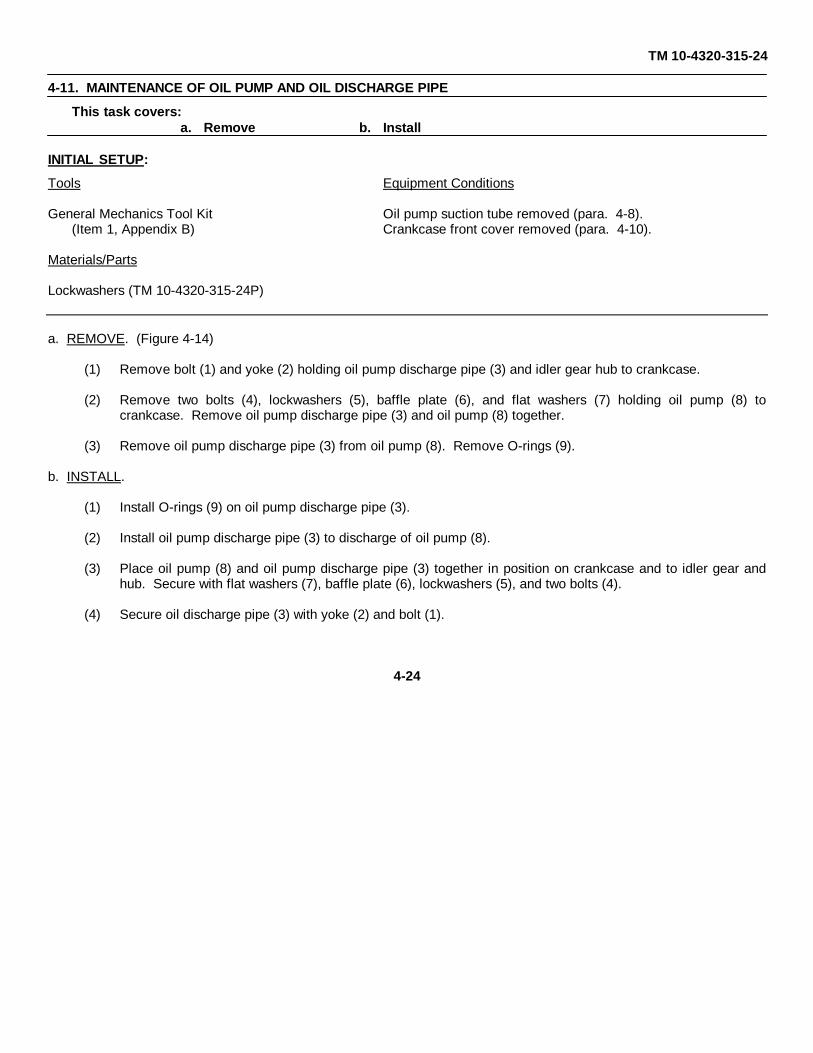
TM 10-4320-315-24
4-11. MAINTENANCE OF OIL PUMP AND OIL DISCHARGE PIPE
This task covers: a. Remove b. Install
INITIAL SETUP:
Tools Equipment Conditions
General Mechanics Tool Kit Oil pump suction tube removed (para. 4-8).(Item 1, Appendix B) Crankcase front cover removed (para. 4-10).
Materials/Parts
Lockwashers (TM 10-4320-315-24P)
a. REMOVE. (Figure 4-14)
(1) Remove bolt (1) and yoke (2) holding oil pump discharge pipe (3) and idler gear hub to crankcase.
(2) Remove two bolts (4), lockwashers (5), baffle plate (6), and flat washers (7) holding oil pump (8) tocrankcase. Remove oil pump discharge pipe (3) and oil pump (8) together.
(3) Remove oil pump discharge pipe (3) from oil pump (8). Remove O-rings (9).
b. INSTALL.
(1) Install O-rings (9) on oil pump discharge pipe (3).
(2) Install oil pump discharge pipe (3) to discharge of oil pump (8).
(3) Place oil pump (8) and oil pump discharge pipe (3) together in position on crankcase and to idler gear andhub. Secure with flat washers (7), baffle plate (6), lockwashers (5), and two bolts (4).
(4) Secure oil discharge pipe (3) with yoke (2) and bolt (1).
4-24

TM 10-4320-315-24
4-11. MAINTENANCE OF OIL PUMP AND OIL DISCHARGE PIPE - (Cont)
Figure 4-14. Oil Pump and Oil Pump Discharge Pipe
4-25

TM 10-4320-315-24
4-12. MAINTENANCE OF CRANKCASE REAR COVER
This task covers: a. Remove b. Install
INITIAL SETUP:
General Safety Instructions
ToolsWARNING
General Mechanics Tool Kit(Item 1, Appendix B Solvent may cause toxic fumes. To prevent
Removal Device, Crankshaft Oil Seals personal injury, work only in well-ventilated area .(Item 13, Appendix B) DO NOT breath fumes for a long time .
Angle of Turn Indicator(Item 4, Appendix B) Solvent is flammable. To prevent fire or
explosion, DO NOT bring open flame or sparksMaterials/Parts near solvent.
Rags (Item 12, Appendix C) Equipment ConditionsCleaning Solvent (Item 19, Appendix C)Sealant (Silicone) (Item 16, Appendix C) Flywheel housing removed (para. 3-26).Oil (Item 10, Appendix C) Oil pan removed (para. 4-7).
a. REMOVE. (Figure 4-15)
(1) Remove bolts (1) and flat washers (2) holding crankcase rear cover (3) to crankcase (4).
(2) Remove crankcase rear cover (3).
Figure 4-15. Crankcase Rear Cover
4-26
TM 10-4320-315-24
4-12. MAINTENANCE OF CRANKCASE REAR COVER - (Cont)
b. INSTALL.
(1) Clean gasket surfaces with rags and cleaning solvent.
(2) Install crankshaft sealing ring (5) in crankcase rear cover (3), lip toward crankcase side of rear cover. Outerside of sealing ring should be even with outer side of rear cover.
(3) Apply sealant to mating surfaces on crankcase rear cover (3) and crankcase (4),
(4) Lightly coat sealing lip of sealing ring (5) with oil.
(5) Install crankcase rear cover (3) on crankcase (4). Secure with flat washers (2) and bolts (1).
4-27

TM 10-4320-315-24
4-13. MAINTENANCE OF CRANKSHAFT
This task covers: a. Remove b. Inspect c. Install
INITIAL SETUP:
Tools Equipment Conditions
General Mechanics Tool Kit Crankshaft pulley removed (para. 3-27).(Item 1, Appendix B) Connecting rods removed (para. 4-9).
Inside and Outside Micrometer Crankcase front cover removal (para. 4-10).(Item 3, Appendix B) Oil pump removed (para. 4-11).
Angle-Of-Turn Indicator Crankcase rear cover (para. 4-12).(Item 4, Appendix B)
Wrench, Torque Reading(Item 3, Appendix B)
Materials/Parts
Tags (Item 21, Appendix C)
a. REMOVE. (Figure 4-16)
Figure 4-16. Crankshaft
4-28
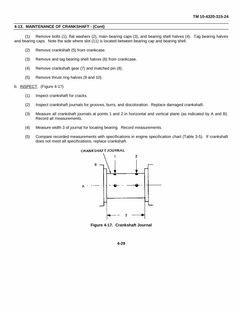
TM 10-4320-315-24
4-13. MAINTENANCE OF CRANKSHAFT - (Cont)
(1) Remove bolts (1), flat washers (2), main bearing caps (3), and bearing shell halves (4). Tag bearing halvesand bearing caps. Note the side where slot (11) is located between bearing cap and bearing shell.
(2) Remove crankshaft (5) from crankcase.
(3) Remove and tag bearing shell halves (6) from crankcase.
(4) Remove crankshaft gear (7) and matched pin (8).
(5) Remove thrust ring halves (9 and 10).
b. INSPECT. (Figure 4-17)
(1) Inspect crankshaft for cracks.
(2) Inspect crankshaft journals for grooves, burrs, and discoloration. Replace damaged crankshaft.
(3) Measure all crankshaft journals at points 1 and 2 in horizontal and vertical plane (as indicated by A and B).Record all measurements.
(4) Measure width 3 of journal for locating bearing. Record measurements.
(5) Compare recorded measurements with specifications in engine specification chart (Table 3-5). If crankshaftdoes not meet all specifications, replace crankshaft.
Figure 4-17. Crankshaft Journal
4-29

TM 10-4320-315-24
4-13. MAINTENANCE OF CRANKSHAFT - (Cont)
c. INSTALL.
(1) Install crankshaft gear (7) and matched pin (8) on crankshaft (5), with identification mark on gear facing awayfrom crankshaft.
(2) Insert bearing shells (4 and 6) in crankcase bores and in bearing caps (3).
(3) Lightly coat thrust ring halves (10) with grease. Install smooth side of thrust ring halves in first bearing boreof crankcase.
(4) Install thrust ring halves (9) on first bearing cap, with smooth side of thrust ring against bearing cap.
(5) Coat crankshaft (5) of journals with oil.
(6) Install crankshaft (5) in crankcase.
(7) Install bearing caps (3) and screws in crankcase with flat washers (2) and bolts (1). Ensure slot (11) betweenbearing cap and bearing shell is in the same location as when removed.
NOTE
Start torque at center bearing cap. Work from side to side with end bearing caps torqued last.
(8) Torque bearing capscrews to 22 ft•lbs (29.8 N•m).
(9) Using angle-of-turn indicator tighten bearing capscrews 40°. Tighten again to 65°.
(10) Push crankshaft toward front of engine.
NOTE
Clearance can be adjusted by removing bearing cap and replacing thrust ring halves withappropriate size thrust ring halves.
(11) Measure end clearance at number one bearing. Correct clearance is 0.0055-0.0117 in. (0.1397-0.2972mm).
4-30

TM 10-4320-315-24
4-14. MAINTENANCE OF CAMSHAFT AND TAPPETS
This task covers: a. Remove b. Inspect c. Disassembled. Repair e. Assemble
INITIAL SETUP:
Tools Equipment Conditions
General Mechanics Tool Kit Oil pump removed (para. 4-11).(Item 1, Appendix B) Crankcase front cover removed (para. 4-10).
Inside and Outside Micrometer Pushrods removed (para. 3-30).(Item 3, Appendix B)
Inserter and Removal Device,Camshaft bushing/Bearings(Item 14, Appendix B)
a. REMOVE. (Figure 4-18)
(1) Remove plug (1), seal ring (2), cup (3), and spring (4) from crankcase (5).
(2) With crankcase laying upside down, remove camshaft (6) from crankcase (5).
(3) Remove thrust washer (7) from camshaft (6) by moving along camshaft journals. Use care not to scratch ormark journals.
(4) Remove tappets (8) from crankcase (5).
Figure 4-18. Camshaft and Tappets
4-31
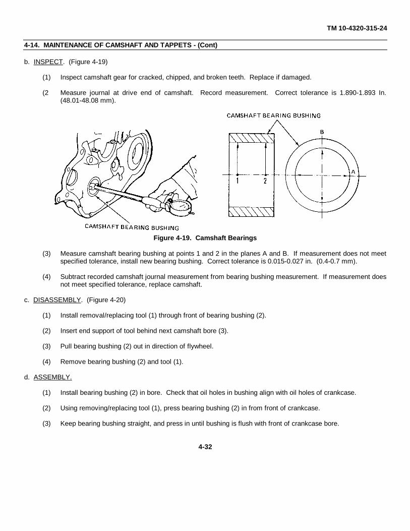
TM 10-4320-315-24
4-14. MAINTENANCE OF CAMSHAFT AND TAPPETS - (Cont)
b. INSPECT. (Figure 4-19)
(1) Inspect camshaft gear for cracked, chipped, and broken teeth. Replace if damaged.
(2 Measure journal at drive end of camshaft. Record measurement. Correct tolerance is 1.890-1.893 In.(48.01-48.08 mm).
Figure 4-19. Camshaft Bearings
(3) Measure camshaft bearing bushing at points 1 and 2 in the planes A and B. If measurement does not meetspecified tolerance, install new bearing bushing. Correct tolerance is 0.015-0.027 in. (0.4-0.7 mm).
(4) Subtract recorded camshaft journal measurement from bearing bushing measurement. If measurement doesnot meet specified tolerance, replace camshaft.
c. DISASSEMBLY. (Figure 4-20)
(1) Install removal/replacing tool (1) through front of bearing bushing (2).
(2) Insert end support of tool behind next camshaft bore (3).
(3) Pull bearing bushing (2) out in direction of flywheel.
(4) Remove bearing bushing (2) and tool (1).
d. ASSEMBLY.
(1) Install bearing bushing (2) in bore. Check that oil holes in bushing align with oil holes of crankcase.
(2) Using removing/replacing tool (1), press bearing bushing (2) in from front of crankcase.
(3) Keep bearing bushing straight, and press in until bushing is flush with front of crankcase bore.
4-32

TM 10-4320-315-24
4-14. MAINTENANCE OF CAMSHAFT AND TAPPETS - (Cont)
(4) Remove the removing/replacing tool.
Figure 4-20. Bearing Bushing
e. REPAIR.
Repair consists of replacement of parts.
f. INSTALL. (Figure 4-18)
(1) Lightly coat all parts with oil.
(2) Install tappets (8) in crankcase (5).
(3) Install thrust washer (7) on camshaft (6).
(4) Insert camshaft (6) in crankcase (5).
(5) Install spring (4), cut (3), seal ring (2), and plug (1) into crankcase (5).
4-33

TM 10-4320-315-24
4-15. MAINTENANCE OF CRANKCASE
This task covers: a. Disassembly b. Inspectc. Repair d. Assembly
INITIAL SETUP:
Tools Equipment Conditions
General Mechanics Tool Kit Camshaft and tappets removed (para. 4-14).(Item 1, Appendix B) Crankshaft removed (para. 4-13).
Materials/Parts
Lockwashers (TM 10-4320-315-24P)
a. DISASSEMBLE. (Figure 4-21)
(1) Remove plugs (1, 2, 3, 4, 5, and 6) and sealing rings (7, 8, 9, 10, and 11).
(2) Remove clamping bushings (12).
(3) Remove piston cooling nozzle (13) and lockwasher (14) (for piston pin cooling).
b. INSPECT.
(1) Check oil ducts for free passage. Clean and remove obstructions.
(2) Check walls and bearing webs for cracks. Replace crankcase if cracks are found.
(3) Check condition of bearing bores. If wear marks on bearing shells are not noticeable, check dimensions ofbearing bores. Correct dimension is 3.0535-3.0542 in. (77.5-77.519 mm).
c. REPAIR.
Repair is accomplished by replacement of parts.
d. ASSEMBLE.
(1) Install sealing rings (7, 8, 9, 10, and 11) and plugs (1, 2, 3, 4, 5, and 6).
(2) Install clamping bushings (12).
(3) Install lockwashers (14) and piston cooling nozzles (13).
4-34

TM 10-4320-315-24
4-15. MAINTENANCE OF CRANKCASE.
Figure 4-21. Crankcase
4-35/(4-36 blank)
TM 10-4320-315-24
APPENDIX A
REFERENCES
A-1. SCOPE. This appendix lists all forms, field manuals, technical manuals, and miscellaneous publicationsreferenced in this manual.
A-2. FORMS.
Recommended Changes to Equipment Technical Publications ..................................................................... DA-2028-2Recommended Changes to Publications and Blank Forms ................................................................................DA-2028Quality Deficiency Report ....................................................................................................................................SF-368Equipment Inspection and Maintenance Worksheet ..........................................................................................DA-2404
A-3. FIELD MANUALS.
First Aid Procedures ........................................................................................................................................ FM 21-11
A-4. TECHNICAL MANUALS.
General Repair of Electrical Components .................................................................................................... TM 43-0158Operators Manual for Welding Theory and Application .................................................................................... TM 9-237Operator's Manual ............................................................................................................................TM 10-4320-315-10Repair Parts and Special Tools List ............................................................................................... TM 10-4320-315-24PLubrication Order .............................................................................................................................LO 10-4320-315-12Unit, Direct Support, and General Support
Maintenance Manual ..................................................................................................................TM 10-4320-315-24Painting Instructions for Field Use ............................................................................................................... TM 43-0139Destruction of Equipment to Prevent Enemy Use ..................................................................................... TM 750-244-3Operator's, Organizational, Direct Support, and General
Support Maintenance Manual for Lead-Acid Storage Batteries .................................................... TM 9-6140-200-14
A-5. MISCELLANEOUS PUBLICATIONS.
The Army Maintenance Management System (TAMMS) ...............................................................DA Pamphlet 738-750Joint Regulation Governing the Use and Application
of Uniform Source Maintenance and Recoverability (SMR) Codes............................................................AR 700-82Army Material Maintenance Concepts and Policies ...........................................................................................AR 750-1
A-1/(A-2 blank)

TM 10-4320-315-24
APPENDIX B
MAINTENANCE ALLOCATION CHART
SECTION I. INTRODUCTION
B-1. GENERAL. This section provides a general explanation of all maintenance and repair functions authorized atvarious maintenance categories.
a. The Maintenance Allocation Chart (MAC) in Section II designates overall authority and responsibility for theperformance of maintenance functions on the identified end item or component. The application of the maintenancefunctions to the end item or component will be consistent with the capacities and capabilities of the designatedmaintenance categories.
b. Section III lists the tools and test equipment (both special tools and common tool sets) required for eachmaintenance function as referenced from Section II.
c. Section IV contains supplemental instructions and explanatory notes for a particular maintenance function.
B-2. MAINTENANCE FUNCTIONS . Maintenance functions will be limited to and defined as follows:
a. Inspect. To determine the serviceability of an item by comparing its physical, mechanical, and/or electricalcharacteristics with established standards through examination (e.g., by sight, sound, or feel).
b. Test. To verify serviceability by measuring the mechanical, pneumatic, hydraulic, or electrical characteristics ofan item and comparing those characteristics with prescribed standards.
c. Service. Operations required periodically to keep an item in proper operating condition; i.e., to clean (includesdecontaminate, when required), to preserve, to drain, to paint, or to replenish fuel, lubricants, chemical fluids, or gases.
d. Adjust. To maintain or regulate, within prescribed limits, by bringing into proper or exact position, or by settingthe operating characteristics to specified parameters.
e. Align To adjust specified variable elements of an item to bring about optimum or desired performance.
f. Calibrate. To determine and cause corrections to be made or to be adjusted on instruments or test, measuring,and diagnostic equipments used in precision measurement. Consists of comparisons of two instruments, one of whichis a certified standard of known accuracy, to detect and adjust any discrepancy in the accuracy of the instrument beingcompared.
g. Remove/Install. To remove and install the same item when required to perform service or other maintenancefunctions. Install may be the act of emplacing, seating, or fixing into position a spare, repair part, or module (componentor assembly) in a manner to allow the proper functioning of an equipment or system.
h. Replace. To remove an unserviceable item and install a serviceable counterpart in its place. "Replace" isauthorized by the MAC and is shown as the third position code of the SMR code.
B-1

TM 10-4320-315-24
i. Repair. The application of maintenance services', including fault location/troubleshooting2,removal/installation, and disassembly/assembly3 procedures, and maintenance actions' to identify troubles and restoreserviceability to an item by correcting specific damage, fault, malfunction, or failure in a part, subassembly, module(component or assembly), end item, or system.
j. Overhaul. That maintenance effort (service/action) prescribed to restore an item to a completelyserviceable/operational condition as required by maintenance standards in appropriate technical publications (i.e.,DMWR). Overhaul is normally the highest degree of maintenance performed by the Army. Overhaul does not normallyreturn an item to like new condition.
k. Rebuild. Consists of those services/actions necessary for the restoration of unserviceable equipment to a likenew condition in accordance with original manufacturing standards. Rebuild is the highest degree of materialmaintenance applied to Army equipment. The rebuild operation includes the act of returning to zero those agemeasurements (hours/miles, etc.) considered in classifying Army equipment/components.
B-3. EXPLANATION OF COLUMNS IN THE MAC, SECTION II.
a. Column 1. Group Number. Column 1 lists functional group code numbers, the purpose of which is to identifymaintenance significant components, assemblies, subassemblies, and modules with the next higher assembly. End itemgroup number shall be "00".
b. Column 2. Component/Assembly. Column 2 contains the names of components, assemblies, subassemblies,and modules for which maintenance is authorized.
c. Column 3. Maintenance Function. Column 3 lists the functions to be performed on the item listed in Column 2.(For detailed explanation of these functions, see paragraph B-2.)
d. Column 4, Maintenance Category. Column 4 specifies, by the listing of a work time figure in the appropriatesubcolumn(s), the category of maintenance authorized to perform the function listed in Column 3. This figure representsthe active time required to perform that maintenance function at the indicated category of maintenance. If the number orcomplexity of the tasks within the listed maintenance function vary at different maintenance categories, appropriate worktime figures will be shown for each category. The work time figure represents the average time required to restore anitem (assembly, subassembly, component, module, end item, or system) to a serviceable condition under typical fieldoperating conditions. This time includes preparation time (including any necessary disassembly/assembly time),troubleshooting/fault location time, and quality assurance/quality control time in addition to the time required to performthe specific tasks identified for the maintenance functions authorized in the maintenance allocation chart. The symboldesignations for the various maintenance categories are as follows:
C ............................Operator or CrewO............................Unit MaintenanceF ............................Direct Support MaintenanceH ............................General Support MaintenanceD ............................Depot Maintenance
1Services - inspect, test, service, adjust, align, calibrate, and/or replace.2Fault locate/troubleshoot - The process of investigating and detecting the cause of equipment malfunctioning; the
act of isolating a fault within a system or unit under test (UUT).3Disassemble/assemble - encompasses the step-by-step taking apart (or breakdown) of a spare/functional group
coded item to the level of its least componency identified as maintenance significant (i.e., assigned an SMR code) for thecategory of maintenance under consideration.
4Actions - welding, grinding, riveting, straightening, facing, remachinery, and/or resurfacing.
B-2

TM 10-4320-315-24
e. Column 5, Tools and Equipment. Column 5 specifies, by code, those common tool sets (not individual tools) andspecial tools, TMDE, and support equipment required to perform the designated function.
f. Column 6, Remarks. This column shall, when applicable, contain a letter code, in alphabetic order, which shallbe keyed to the remarks contained in Section IV.
B-4. EXPLANATION OF COLUMNS IN TOOL AND TEST EQUIPMENT REQUIREMENTS, SECTION III.
a. Column 1, Reference Code. The tool and test equipment reference code correlates with a code used in theMAC, Section II, Column 5.
b. Column 2, Maintenance Category. The lowest category of maintenance authorized to use the tool or testequipment.
c. Column 3, Nomenclature. Name or identification of the tool or test equipment.
d. Column 4, National Stock Number. The national stock number of the tool or test equipment.
e. Column 5, Tool Number. The manufacturer's part number.
B-5. EXPLANATION OF COLUMNS IN REMARKS, SECTION IV.
a. Column 1. Reference Code. The code recorded in the MAC, Section II, Column 6.
b. Column 2. Remarks. This column lists information pertinent to the maintenance function being performed asindicated in the MAC, Section II.
B-3

TM 10-4320-315-24
SECTION II. MAINTENANCE ALLOCATION CHART(1) (2) (3) (4) (5) (6)
MAINTENANCE CATEGORY TOOLSGROUP COMPONENT/ASSEMBLY MAINTENANCE AND
NUMBER FUNCTION C O F H D EQPT REMARKS
00 Pumping assembly01 Noise Enclosure Repair 1.0 10101 Roof Inspect 0.1
Replace 3.0 10102 Plate, Left Rear Inspect 0.1
Replace 1.0 10103 Plate, Right Rear Inspect 0.1
Replace 1.0 10104 Panel, Left Rear Inspect 0.1
Replace 1.0 10105 Panel, Right Rear Inspect 0.1
Replace 1.0 10106 Panel, Front Inspect 0.1
Replace 1.0 1010601 Cover Assy Inspect 0.1
Replace 1.0 10107 Panel, Left Inspect 0.1
Replace 1.0 1010701 Cover Assy Inspect 0.1
Replace 1.0 1010702 Door Assy Inspect 0.1
Replace 1.0 10108 Panel, Left Inspect 0.1
Replace 1.0 1010801 Door Assy Inspect 0.1
Replace 1.0 10109 Panel, Right Inspect 0.1
Replace 1.0 1010901 Door Assy Inspect 0.1
Replace 1.0 1010902 Door Assy Inspect 0.1
Replace 1.0 10110 Panel Assy, Control Inspect 0.1
Replace 1.0 1011001 Cover, Hinged Inspect 0.1
Control Panel Replace 1.0 10111 Frame Inspect 0.1
Replace 0.602 Electrical System
B-4

TM 10-4320-315-24SECTION II. MAINTENANCE ALLOCATION CHART (Cont)
(1) (2) (3) (4) (5) (6)MAINTENANCE CATEGORY TOOLS
GROUP COMPONENT/ASSEMBLY MAINTENANCE ANDNUMBER FUNCTION C O F H D EQPT REMARKS
0201 Battery Assy Inspect 0.1 1Service 0.5 1Replace 1.0 1
0202 Control Panel Assembly Inspect 0.2Replace 2.0 1
020201 Engine High Temperature, Replace 0.5 1Overspeed, and Low OilIndicators
020202 Engine Temperature Oil Replace 0.5 1Pressure, and Fuel TankGages
020203 Engine Volts Meter Replace 0.5 1020204 Tachometer and Run Replace 0.5 1
Time Meter020205 Pump Pressure Gages Replace 0.5 1020206 Electrical Toggle Replace 0.5 1
Switches020207 Lights and Auto Throttle Replace 0.5 1
Rheostats020208 Pressure Control Module Replace 1.0 1020209 Governor Control Module Replace 1.0 1
Adjust 0.5020210 Engine Protection System Replace 1.0 1
Module020211 Control Panel Wire Replace 1.0 1
Harness Repair 1.0 1,5020212 Governor Actuator Replace 1.0 1
Assembly03 Engine Accessories0301 Exhaust Pipes and Muffler Inspect 0.1 0.5
Replace 1.0 10302 Air Filter Gage and Hose Replace 0.20303 Auto Defeat Cable Replace 0.8 10304 Manual Throttle Control Replace 0.8 1
Cable0305 Cold Start Aid Hose, Inspect 0.1
Bottle and Cable Replace 1.0 10306 Engine Wiring Harness Replace 1.0 1
Repair 1.0 1,50307 Magnetic Pickup Tube Replace 0.8 1
(MPU)
B-5

TM 10-4320-315-24
SECTION II. MAINTENANCE ALLOCATION CHART (Cont)
(1) (2) (3) (4) (5) (6)MAINTENANCE CATEGORY TOOLS
GROUP COMPONENT/ASSEMBLY MAINTENANCE ANDNUMBER FUNCTION C O F H D EQPT REMARKS
0308 Engine Temperature and Replace 1.0 1Oil Pressure Switchesand Senders
0309 Fuel Valves and Lines Replace 1.0 10310 Air Cleaner and Air Inspect 0.2
Intake Line Service 0.2Replace 1.0 1
0311 Engine Oil Drain Line Replace 0.8 104 Engine, Assembly0401 Engine Inspect 0.4
Service 1.5 1,20Replace 8.0 1
0402 V-Belts Inspect 0.1Replace 1.0 1Adjust 0.2 1
0403 Cooling Blower Assembly Inspect 0.2Replace 1.0 1Repair 1.0 1
0404 Fuel Lines Inspect 0.1Replace 0.5 1
0405 Filter Assembly, Fuel Inspect 0.5Service 1.0 1Replace 1.0 1
0406 Tensioner Assembly, Inspect 0.5V-Belt Replace 1.0 1
0407 Tube Assy, Oil Inlet Inspect 0.2Replace 1.0 1
0408 Lube Oil Filter Assy Replace 1.5 10409 Lube Oil Cooler Replace 1.5 10410 Oil Breather Assembly Replace 1.0 10411 Fuel Injection Lines Replace 1.0 10412 Fuel Injectors Inspect 0.2 1
Replace 1.5 1,6,7Repair 2.0 1Test 1.0 1
0413 Fuel Supply Pump Inspect 0.2Replace 1.0 1Repair 1.0 1
0414 Fuel Injection Pump Replace 1.5 1,15,16,17,18
Repair 2.0 B
B-6

TM 10-4320-315-24
SECTION II. MAINTENANCE ALLOCATION CHART - (Cont)
(1) (2) (3) (4) (5) (6)MAINTENANCE CATEGORY TOOLS
GROUP COMPONENT/ASSEMBLY MAINTENANCE ANDNUMBER FUNCTION C O F H D EQPT REMARKS
0415 Alternator Inspect 0.1Replace 1.0 1Repair 3.0 1Test 1.0 3
0416 Starter Assy Inspect 0.1Replace 1.0 1,2Repair 3.0 1Test 1.0 3
0417 Turbocharger and Replace 2.0 1Heat Shield Repair 4.0 B
0418 Air Outlet Frame Replace 1.5 10419 Intake and Exhaust Replace 1.0
Manifolds0420 Air Cowling Replace 1.0 10421 Oil Cooler Discharge Duct Replace 0.5 10422 Flywheel Replace 0.7 10423 Flywheel Housing Replace 0.5 10424 Crankshaft Pulley and Inspect 0.2
Damper Replace 0.6 1,4,3,190425 Front Engine Mount Plate Replace 0.6 1
and Mounting Feet0426 Head Assembly042601 Head Cover Replace 1.0 1,2042602 Rocker Arm Assembly Inspect 0.5 1
Repair 2.0 1Adjust 1.0 1
042603 Cylinder Heads Inspect 0.5Replace 3.0 1,4Repair 3.0 3
0427 Cylinder Liners Inspect 0.5 3Replace 2.0 3Repair 2.0 3
0428 Pistons Inspect 0.5 10Replace 2.0 1
0429 Oil Pan and Baffle Plate Replace 1.0 10430 Oil Pump Suction Tube Replace 0.5 10431 Connecting Rods Inspect 0.5 3
Replace 1.0 3,4,110432 Crankcase Front Cover Replace 1.0 1,12,130433 Oil Pump and Oil Pump Replace 0.5 1
Discharge Pipe
B-7

TM 10-4320-315-24SECTION II. MAINTENANCE ALLOCATION CHART (Cont)
(1) (2) (3) (4) (5) (6)MAINTENANCE CATEGORY TOOLS
GROUP COMPONENT/ASSEMBLY MAINTENANCE ANDNUMBER FUNCTION C O F H D EQPT REMARKS
0434 Crankshaft Rear Cover Inspect 0.1 1,4,13Replace 0.5
0435 Crankshaft Inspect 0.1 3Replace 0.5 1,3,4
0436 Camshaft and Tappets Inspect 0.1 3Replace 1.0 1,14
0437 Crankcase Repair 2.0 105 Pump Assy0501 Suction Line Inspect 0.1
Replace 1.0 1050101 Elbow, Flanged Inspect 0.1
Replace 0.5 1050102 Nipple Suction Inspect 0.1
Replace 0.5 10502 Discharge Line Inspect 0.1
Replace 0.5 1050201 Elbow Flanged Inspect 0.1
Replace 0.5 1050202 Elbow Victaulic Inspect 0.1
Replace 0.5 10503 Pump Inspect 0.1
Replace 2.0 1050301 Body Pump Inspect 0.5
Repair 1.5050302 Housing, Bearing Inspect 0.5
Repair 1.5 1,306 Trailer Assy0601 Lunette Eye Coupler Assy Inspect 0.1060101 Actuator, Brake Inspect 0.5
Replace 2.0 1060102 Brake Lines Inspect 0.1
Replace 1.0 10602 Hand Brake Assy Inspect 0.1
Replace 1.0 1Adjust 0.5
0603 Wiring Harness and Inspect 0.1Tail Lights Replace 1.5 1
0604 Leveling Jacks Inspect 0.1Replace 1.0 1
0605 Tripod Jack Assy Inspect 0.1Replace 1.0 1
B-8

TM 10-4320-315-24
SECTION II. MAINTENANCE ALLOCATION CHART (Cont)
(1) (2) (3) (4) (5) (6)MAINTENANCE CATEGORY TOOLS
GROUP COMPONENT/ASSEMBLY MAINTENANCE ANDNUMBER FUNCTION C O F H D EQPT REMARKS
0606 Reflectors Inspect 0.1Replace 0.7 1
0607 Axle Assy Inspect 0.5Replace 2.0 1,3
060701 Hub Assy Inspect 0.1Replace 1.0 1
060702 Wheel Inspect 0.1Replace 1.0 1,2
060703 Tire Inspect 0.1Replace 0.5 1
0608 Spring and Suspension Kit Inspect 0.1Replace 2.0 1,3
060801 Shock Absorbers Inspect 0.1Replace 1.5 1,2
0609 Chassis Inspect 0.5Repair A
060901 Battery Box Inspect 0.1Replace 0.5 1
B-9

TM 10-4320-315-24SECTION III. TOOL AND TEST EQUIPMENT REQUIREMENTS
(1) (2) (3) (4) (5)REFERENCE MAINTENANC E NOMENCLATURE NATIONAL/NATO TOOL
CODE CATEGORY STOCK NUMBER NUMBER
1 O,F,H Tool Kit, General Mechanic's, 5180-00-177-7033 SC518-90-CL-N26Automotive
2 O Shop Equipment, Automotive 4910-00-754-0654Maintenance and Repair:Organizational Maintenance,Common No. 1
3 F,H Shop Equipment, Automotive 4910-00-754-0705Maintenance and Repair.Field Maintenance, Basic
4 O,F Angle-Of-Turn Indicator 003-0500 (62445)5 O,F Tool Kit, Electric Connector 5180-00-876-93366 F Removal Tool, Fuel Injector 150800 (36719)7 F Removal Tool, Fuel Injectors 110030 (36719)8 F Compressor, Pushrod Spring 003-0501 (62445)9 F Pointer, Dial Segments 003-0678 (36719)10 F Gage, Piston, Keystone Groove 003-0438 (62445)11 F Bushing Insert Device Fixture 030-1079 (62445)12 F Assembly Device, Crankshaft 003-1221 (36719)
Front Oil Seal13 F Removal Device, Crankshaft 003-0733 (62445)
Front and Rear Oil Seals14 H Inserter and Removal Device, 003-0433 (36719)
Camshaft Bushing/Bearings15 F Fixture, Timing 030-1167 (62445)16 F Timer, Graduation Magnetic 003-1189 (62445)17 F Hand Pump, High Pressure 003-0714 (62445)18 F Fuel Bottle, Waste 003-0777 (62445)19 F Tool, Retainer 003-0446 (62445)20 F Eyes, Lifting 223-7759 (62445)
SECTION IV. REMARKS
ReferenceCode Remarks
A Repair by welding. Refer to TM9-237.B Return to Depot for return to manufacturer.
B-10
TM 10-4320-315-24
APPENDIX C
EXPENDABLE/DURABLE SUPPLIES AND MATERIALS LIST
SECTION I. INTRODUCTION
C-1. SCOPE. This appendix list expendable supplies and materials you will need to operate and maintain the pumpingassembly. This listing is for informational purposes only and Is not authority to requisition the listed Items. These itemsare authorized to you by CTA 50-970, Expendable/Durable Items (Except Medical, Class V, Repair Parts, and HeraldicItems), or CTA 8-100, Army Medical Department Expendable/Durable Items.
C-2. EXPLANATION OF COLUMNS.
a. Column (1) - Item Number. This number is assigned to the entry In the listing and is referenced In the narrativeinstructions to identify the material (e.g., faceshield, Item 4, Appendix E).
b. Column (2) - Level. This column Identifies the lowest level of maintenance that requires the listed item.
C - Operator or CrewO - Unit MaintenanceF - Direct Support MaintenanceH - General Support Maintenance
c. Column (3) - National Stock Number. This Is the national stock number assigned to the Item; use it to request orrequisition the item.
d. Column (4) - Description. Indicates the federal item name and, If required, a description to Identify the item.The last line for each item Indicates the Commercial and Government Entry Code (CAGEC) in parentheses followed bythe part number.
e. Column (5) - Unit of Measure (U/M). Indicates the measure used In performing the actual maintenance function.This measure Is expressed by a two-character alphabetical abbreviation (e.g., EA, GL, PR). If the unit of measure differsfrom the unit of Issue, requisition the lowest unit of issue that will satisfy your requirements.
C-1

TM 10-4320-315-24SECTION II. EXPENDABLE/DURABLES SUPPLIES AND MATERIALS LIST
(1) (2) (3) (4) (5)
ITEM NATIONAL STOCK DESCRIPTIONNUMBER LEVEL NUMBER U/M
1 O 8040-00-597-9723 Adhesive, EC-776 PT2 F 5350-00-260-0750 Cloth, Crocus, P-C-451 SH3 C,O 7920-00-044-9281 Cloth, Lint Free EA4 O 4240-00-542-2048 Faceshield EA5 C,O Fluid, Brake (VV-B-680) QT6 C Gloves, Flame Resistant
8416-01-134-8234 Small PR8415-01-134-8232 Medium PR8415-01-134-8233 Large PR8415-01-135-2724 X-Large PR
7 O,F 9150-00-190-0905 Grease, Automotive and Artillery GAA LB(MIL-G-10924) U/I 5 lb can
8 O,F 9150-00-985-7316 Grease, General Purpose (MIL-G-23549) LB1 lb can
9 O 9140-00-286-5286 Oil, Fuel, Diesel DF-1, Winter GL(VV-F-800) Bulk
O 9140-00-286-5294 Oil, Fuel, Diesel DF-2, Regular GL(VV-F-800) Bulk
10 O,H,F 9150-00-265-9428 Oil, Lubricating, OE/HDO 10 GL(MIL-L-2104)
9150-00-265-9435 Oil, Lubricating, OE/HDO 30 GL(MIL-L-2104)Oil, Lubricating, OE/HDO 40 GL(MIL-L-2104)Oil, Lubricating, OE/20W20 (MIL-L-46152) GLOil, Lubricating, OE/10W (MIL-L-46152) GLOil, Lubricating, OE/10W30, ML-3129 GL(MIL-L-46152)Oil, Lubricating, OE/10W40, ML-3107 GL(MIL-L-46152)Oil, Lubricating, OE/5W30, ML-3105 GL(MIL-L-46152)
11 O 5310-00-515-7449 Pin, Cotter, AN960-C4162 EA12 C,O 7920-00-205-1711 Rags, Wiping, Cotton and Cotton-Synthetic EA
A-A-53113 C,O 4240-00-816-3819 Safety Goggles EA14 F Sandpaper, No. 00 PG15 O,F Sealant (MIL-S-22473) PT16 F Sealant (Silicone) PT
1007910 (62445)
C-2

TM 10-4320-315-24SECTION II. EXPENDABLE/DURABLES SUPPLIES AND MATERIALS LIST - Cont
(1) (2) (3) (4) (5)
ITEM NATIONAL STOCK DESCRIPTIONNUMBER LEVEL NUMBER U/M
17 F Sealant, Loctite, RC/601, MIL-R-46082, TUType I
18 O Solder, Rosin Core, SN96, WRAP 2, QQ-S-571 LB19 O,F,H 6850-00-281-1985 Solvent, Dry Cleaning, SD (PD-680, Type II) GL
1 gal can20 O,F Straps, Tie, 117-2104 (62445) BX21 O,F,H 7905-00-537-8954 Tags, Marker22 O 8030-00-889-3535 Tape, Teflon (PTFE) RL23 O,F Water, Distilled (O-E-41D) GL
C-3/(C-4 blank)

TM 10-4320-315-24
APPENDIX DSTANDARD TORQUE VALUE CHART
D-1

TM 10-4320-315-24STANDARD TORQUE VALUE CHART - Cont
D-2
TM 10-4320-315-24ALPHABETICAL INDEX
Subject, Para
A
Administrative Storage, 2-8Air Cleaner and Air Intake Line, 2-39Air Cowling and Oil Cooler Discharge Duct, 3-24Air Filter Gage and Hose, 2-34Air Outlet Frame, 3-22Alternator, 2-52, 3-19Assembly and Preparation For Use, 2-7Auto Defeat Cable, 2-31Auto Select, Throttle Select, and Engine Switches, 2-31Axle, Springs, and Suspension Kit, 3-34
B
Battery Assembly and Battery Box, 2-24Brake Actuator, 2-56Brake Shoes and Wheel Cylinder, 2-59
C
Camshaft and Camshaft Bearings, 4-5Camshaft and Tappets, 3-38Cold Start Hose, Bottle and Cable, 2-33Common Tools and Equipment, 2-1, 3-1Connecting Rods, 3-33Control Panel Assembly, 2-17Control Panel Wire Harness, 2-29Cooling Blower Assembly, 2-42Crankcase, 3-39Crankcase Front Cover, 3-34Crankcase Rear Cover, 3-36Crankshaft, 3-37Crankshaft Pulley and Damper, 3-27Cylinder Head Cover, 2-54Cylinder Heads, 2-55, 3-30Cylinder Liners, 3-29
D
Destruction of Army Material to PreventEnemy Use, 1-3
Direct Support Troubleshooting, 3-4
E
Electrical Switch, 2-23Engine and Pump Assembly, 3-17Engine High Temperature Overspeed and Low
Oil Indicators, 2-18Engine Oil Drain Line, 2-40Engine Protection System Module, 2-28
Subject, Para
E - (Cont)
Engine Temperature and Oil Pressure Switches andSenders, 2-31
Engine Temperature, Oil Pressure, and Fuel TankGages, 2-19
Engine Volts Meter, 2-20Engine Wiring Harness, 2-35Equipment Characteristics, Capabilities, and
Features, 1-9Equipment Data, 1-11Exhaust Pipes and Muffler, 3-16
F
Flywheel, 3-25Flywheel Housing, 3-26Front Mount Plate and Mounting Feet, 3-28Fuel Filter Assembly, 2-43Fuel Injection Lines, 2-49Fuel Injection Pump, 3-18Fuel Injectors, 2-50, 4-3Fuel Line Assemblies, 2-41Fuel Supply Pump, 2-51Fuel Valves and Lines, 2-38Functional Description of Pump Assembly, 1-12
G
General, Unit Preventive Checks and Services, 2-11General, Service Upon Receipt, 2-4General, Troubleshooting Procedures, 3-2Governor Actuator Assembly, 2-30Governor Control Module, 2-27Functional Description of Pumping Assembly, 1-10
H
Hand Brake Assembly, 2-60
I
Intake and Exhaust Manifolds, 3-23Interior Brace, 3-15Introduction, Direct Support Maintenance, 3-5Introduction, General Support Maintenance, 4-2Introduction, Unit Maintenance Procedures, 2-15
J
K
Index-1

TM 10-4320-315-24
Subject, ParaL
Leveling Jacks and Tripod Jack Assembly, 2-62Lights and Auto Throttle Rheostats, 2-25Location and Description of Major Components, 1-10Lube Oil Filter Assembly, 2-46
M
Magnetic Pickup Unit (MPU), 2-36Maintenance Forms, Records, and Reports, 1-2Manual Throttle Control Cable, 2-32Master Cylinder and Brake Lines, 2-57
N
Noise Enclosure, 3-6Noise Enclosure Battery Access Panel, 3-13Noise Enclosure Control Panel, 3-14Noise Enclosure Front Panel, 3-10Noise Enclosure Interior Panels, 3-11Noise Enclosure, Left Panel, 3-12Noise Enclosure, Rear Panels, 3-8Noise Enclosure, Right Panel, 3-9Noise Enclosure, Roof, 3-7Nomenclature Cross-Reference List, 1-8
O
Oil Breather Assembly, 2-48Oil Cooler, 2-47Oil Pan and Baffle Plate, 3-31Oil Pump and Oil Pump Discharge Pipe, 3-35Oil Pump Suction Tube, 3-32
P
Pistons, 3-30PMCS Procedures, 2-13Preparation for Storage or Shipment, 1-4Preparation of Pumping assembly for
Shipment, 2-10Preparation of Pumping assembly for
Storage, 2-9Pressure Control Module, 2-26Principles of Operation, 1-13Pump, 3-33Pump Discharge Line, 3-32Pump Pressure Gages, 2-22Pump Suction Line, 3-31
Q
Quality Assurance/Quality Control (QA/QC), 1-5
Subject, ParaR
Reference Information, 1-8Reflectors, 2-64Repair Parts, 2-3, 3-3Reporting Equipment Improvement
Recommendations (EIRs), 1-6Rocker Arm Assembly, 3-29
S
Safety, Care, and Handling, 1-7Safety Chains, 3-35Scope, 1-1Service Upon Receipt of Equipment, 2-6Shock Absorbers, 2-63Site Requirements, 2-5Special Tools, TMDE, and Support Equipment, 2-2, 3-2Starter, 3-20Starter Assembly, 2-53
T
Tachometer and Run Time Meter, 2-21Turbocharger, 3-21Turbocharger Oil Inlet Tube Assembly, 2-45
U
Unit Preventive Maintenance Checks and Services, 2-12Unit Troubleshooting Procedures, 2-14
V
V-Belts, 2-41V-Belt Tensioner Assembly, 2-44V-Belt Warning Switch, 2-43Valve Adjustment, 2-55
W
Wheel, Tire, and Hub Assembly, 2-58Wiring Harness and Tail Lights, 2-61
X
Y
Z
Index-2


The Metric System and Equivalents
Linear Measure Liquid Measure
1 centiliter = 10 milliters = .34 fl. ounce1 centimeter = 10 millimeters = .39 inch 1 deciliter = 10 centiliters = 3.38 fl. ounces1 decimeter = 10 centimeters = 3.94 inches 1 liter = 10 deciliters = 33.81 fl. ounces1 meter = 10 decimeters = 39.37 inches 1 dekaliter = 10 liters = 2.64 gallons1 dekameter = 10 meters = 32.8 feet 1 hectoliter = 10 dekaliters = 26.42 gallons1 hectometer = 10 dekameters = 328.08 feet 1 kiloliter = 10 hectoliters = 264.18 gallons1 kilometer = 10 hectometers = 3,280.8 feet
Square MeasureWeights
1 sq. centimeter = 100 sq. millimeters = .155 sq. inch1 centigram = 10 milligrams = .15 grain 1 sq. decimeter = 100 sq. centimeters = 15.5 sq. inches1 decigram = 10 centigrams = 1.54 grains 1 sq. meter (centare) = 100 sq. decimeters = 10.76 sq. feet1 gram = 10 decigram = .035 ounce 1 sq. dekameter (are) = 100 sq. meters = 1,076.4 sq. feet1 decagram = 10 grams = .35 ounce 1 sq. hectometer (hectare) = 100 sq. dekameters = 2.47 acres1 hectogram = 10 decagrams = 3.52 ounces 1 sq. kilometer = 100 sq. hectometers = .386 sq. mile1 kilogram = 10 hectograms = 2.2 pounds1 quintal = 100 kilograms = 220.46 pounds Cubic Measure1 metric ton = 10 quintals = 1.1 short tons
1 cu. centimeter = 1000 cu. millimeters = .06 cu. inch1 cu. decimeter = 1000 cu. centimeters = 61.02 cu. inches1 cu. meter = 1000 cu. decimeters = 35.31 cu. feet
Approximate Conversion Factors
To change To Multiply by To change To Multiply by
inches centimeters 2.540 ounce-inches Newton-meters .007062feet meters .305 centimeters inches .394yards meters .914 meters feet 3.280miles kilometers 1.609 meters yards 1.094square inches square centimeters 6.451 kilometers miles .621square feet square meters .093 square centimeters square inches .155square yards square meters .836 square meters square feet 10.764square miles square kilometers 2.590 square meters square yards 1.196acres square hectometers .405 square kilometers square miles .386cubic feet cubic meters .028 square hectometers acres 2.471cubic yards cubic meters .765 cubic meters cubic feet 35.315fluid ounces milliliters 29,573 cubic meters cubic yards 1.308pints liters .473 milliliters fluid ounces .034quarts liters .946 liters pints 2.113gallons liters 3.785 liters quarts 1.057ounces grams 28.349 liters gallons .264pounds kilograms .454 grams ounces .035short tons metric tons .907 kilograms pounds 2.205pound-feet Newton-meters 1.356 metric tons short tons 1.102pound-inches Newton-meters .11296
Temperature (Exact)
°F Fahrenheit 5/9 (after Celsius °Ctemperature subtracting 32) temperature

PIN: 070880-000

This fine document...
Was brought to you by me:
Liberated Manuals -- free army and government manuals
Why do I do it? I am tired of sleazy CD-ROM sellers, who take publicly available information, slap “watermarks” and other junk on it, and sell it. Those masters of search engine manipulation make sure that their sites that sell free information, come up first in search engines. They did not create it... They did not even scan it... Why should they get your money? Why are not letting you give those free manuals to your friends?
I am setting this document FREE. This document was made by the US Government and is NOT protected by Copyright. Feel free to share, republish, sell and so on.
I am not asking you for donations, fees or handouts. If you can, please provide a link to liberatedmanuals.com, so that free manuals come up first in search engines:
<A HREF=http://www.liberatedmanuals.com/>Free Military and Government Manuals</A>
– SincerelyIgor Chudovhttp://igor.chudov.com/
– Chicago Machinery Movers