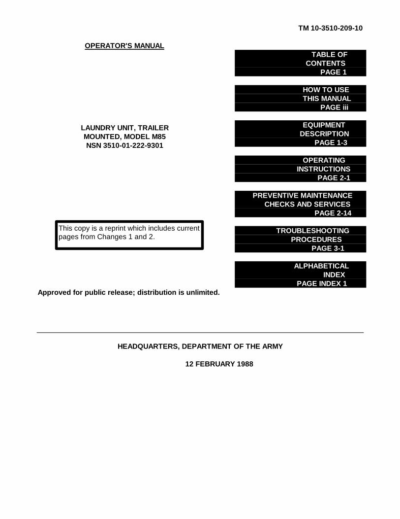
tm 10-3510-209-10 operator's manual table of contents … · tm 10-3510-209-10 how to use this...
TRANSCRIPT
TM 10-3510-209-10
OPERATOR'S MANUALTABLE OF
CONTENTSPAGE 1
HOW TO USETHIS MANUAL
PAGE iii
EQUIPMENTDESCRIPTION
PAGE 1-3
OPERATINGINSTRUCTIONS
PAGE 2-1
PREVENTIVE MAINTENANCECHECKS AND SERVICES
PAGE 2-14
TROUBLESHOOTINGPROCEDURES
PAGE 3-1
ALPHABETICALINDEX
PAGE INDEX 1Approved for public release; distribution is unlimited.
HEADQUARTERS, DEPARTMENT OF THE ARMY
12 FEBRUARY 1988
LAUNDRY UNIT, TRAILERMOUNTED, MODEL M85NSN 3510-01-222-9301
This copy is a reprint which includes currentpages from Changes 1 and 2.

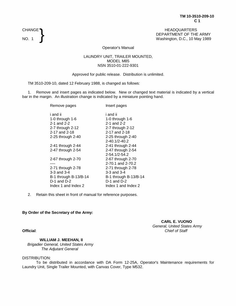
TM 10-3510-209-10C2
CHANGE HEADQUARTERSDEPARTMENT OF THE ARMY
NO. 2 WASHINGTON, D.C., 22 May 1991
Operator's Manual
LAUNDRY UNIT, TRAILER MOUNTED,MODEL M85
NSN 3510-01-222-9301
Approved for public release; distribution is unlimited.
TM 10-3510-209-10, 12 February 1988 is changed as follows:
1. Remove and insert pages as indicated below. New or changed text material is indicated by a verticalbar in the margin. An illustration change is indicated by a miniature pointing hand.
Remove pages Insert pages
2-3 and 2-4 2-3 and 2-4
2. Retain this sheet in front of manual for reference purposes.
By Order of the Secretary of the Army:
CARL E. VUONOGeneral, United States Army
Chief of Staff
Official:
PATRICIA P. HICKERSONColonel, United States Army
The Adjutant General
DISTRIBUTION:To be distributed in accordance with DA Form 12-25E, (qty rqr block no. 4251).
TM 10-3510-209-10C 1
CHANGE HEADQUARTERSDEPARTMENT OF THE ARMY
NO. 1 Washington, D.C., 10 May 1989
Operator's Manual
LAUNDRY UNIT, TRAILER MOUNTED,MODEL M85
NSN 3510-01-222-9301
Approved for public release. Distribution is unlimited.
TM 3510-209-10, dated 12 February 1988, is changed as follows:
1. Remove and insert pages as indicated below. New or changed text material is indicated by a verticalbar in the margin. An illustration change is indicated by a miniature pointing hand.
Remove pages Insert pages
i and ii i and ii1-0 through 1-6 1-0 through 1-62-1 and 2-2 2-1 and 2-22-7 through 2-12 2-7 through 2-122-17 and 2-18 2-17 and 2-182-25 through 2-40 2-25 through 2-40
2-40.1/2-40.22-41 through 2-44 2-41 through 2-442-47 through 2-54 2-47 through 2-54
2-54.1/2-54.22-67 through 2-70 2-67 through 2-70---- 2-70.1 and 2-70.22-71 through 2-78 2-71 through 2-783-3 and 3-4 3-3 and 3-4B-1 through B-13/B-14 B-1 through B-13/B-14D-1 and D-2 D-1 and D-2Index 1 and Index 2 Index 1 and Index 2
2. Retain this sheet in front of manual for reference purposes.
By Order of the Secretary of the Army:
CARL E. VUONOGeneral, United States Army
Official: Chief of Staff
WILLIAM J. MEEHAN, IIBrigadier General, United States Army
The Adjutant General
DISTRIBUTION:To be distributed in accordance with DA Form 12-25A, Operator's Maintenance requirements for
Laundry Unit, Single Trailer Mounted, with Canvas Cover, Type M532.
}
TM 10-3510-209-10
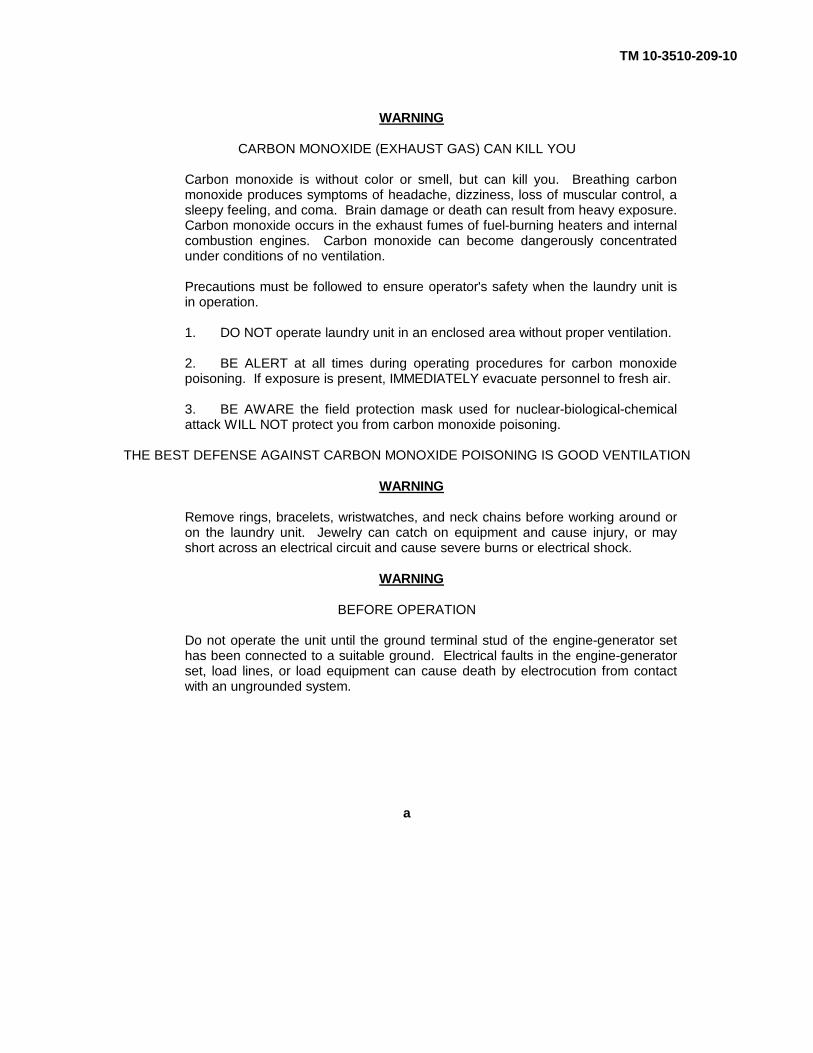
WARNING
CARBON MONOXIDE (EXHAUST GAS) CAN KILL YOU
Carbon monoxide is without color or smell, but can kill you. Breathing carbonmonoxide produces symptoms of headache, dizziness, loss of muscular control, asleepy feeling, and coma. Brain damage or death can result from heavy exposure.Carbon monoxide occurs in the exhaust fumes of fuel-burning heaters and internalcombustion engines. Carbon monoxide can become dangerously concentratedunder conditions of no ventilation.
Precautions must be followed to ensure operator's safety when the laundry unit isin operation.
1. DO NOT operate laundry unit in an enclosed area without proper ventilation.
2. BE ALERT at all times during operating procedures for carbon monoxidepoisoning. If exposure is present, IMMEDIATELY evacuate personnel to fresh air.
3. BE AWARE the field protection mask used for nuclear-biological-chemicalattack WILL NOT protect you from carbon monoxide poisoning.
THE BEST DEFENSE AGAINST CARBON MONOXIDE POISONING IS GOOD VENTILATION
WARNING
Remove rings, bracelets, wristwatches, and neck chains before working around oron the laundry unit. Jewelry can catch on equipment and cause injury, or mayshort across an electrical circuit and cause severe burns or electrical shock.
WARNING
BEFORE OPERATION
Do not operate the unit until the ground terminal stud of the engine-generator sethas been connected to a suitable ground. Electrical faults in the engine-generatorset, load lines, or load equipment can cause death by electrocution from contactwith an ungrounded system.
a
TM 10-3510-209-10
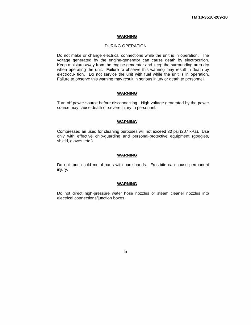
WARNING
DURING OPERATION
Do not make or change electrical connections while the unit is in operation. Thevoltage generated by the engine-generator can cause death by electrocution.Keep moisture away from the engine-generator and keep the surrounding area drywhen operating the unit. Failure to observe this warning may result in death byelectrocu- tion. Do not service the unit with fuel while the unit is in operation.Failure to observe this warning may result in serious injury or death to personnel.
WARNING
Turn off power source before disconnecting. High voltage generated by the powersource may cause death or severe injury to personnel.
WARNING
Compressed air used for cleaning purposes will not exceed 30 psi (207 kPa). Useonly with effective chip-guarding and personal-protective equipment (goggles,shield, gloves, etc.).
WARNING
Do not touch cold metal parts with bare hands. Frostbite can cause permanentinjury.
WARNING
Do not direct high-pressure water hose nozzles or steam cleaner nozzles intoelectrical connections/junction boxes.
b

TM 10-3510-209-10
TECHNICAL MANUAL HEADQUARTERSNO. 10-3510-209-10 DEPARTMENT OF THE ARMY
Washington, D.C. 12 February 1988
OPERATOR'S MANUAL
FOR THE TRAILER-MOUNTED LAUNDRY UNITMODEL M85
NSN 3510-01-222-9301
REPORTING ERRORS AND RECOMMENDING IMPROVEMENTS
You can help improve this manual. If you find any mistakes or if you know of a way to improve the procedures,please let us know. Mail your letter, DA Form 2028 (Recommended Changes to Publications and BlankForms), or DA Form 2028-2 located in the back of this manual direct to: Commander, US Army Troop SupportCommand, ATTN: AMSTR-MCTS, 4300 Goodfellow Blvd., St. Louis, MO 63120-1798. A reply will befurnished to you.
Approved for public release; distribution is unlimited.
TABLE OF CONTENTSPage
HOW TO USE THIS MANUAL................................................................ iii
CHAPTER 1. INTRODUCTION
Section I. General Information ................................................................................ 1-1
Section II. Equipment Description ............................................................................ 1-3
Section III. Technical Principles of Operation............................................................ 1-9
CHAPTER 2. OPERATING INSTRUCTIONS
Section I. Description and Use of Operator's Controlsand Indicators.................................................................................. 2-1
Section II. Preventive Maintenance Checks and Services (PMCS) .......................... 2-14
Section III. Operation Under Usual Conditions ......................................................... 2-30
Section IV. Operation Under Unusual Conditions ..................................................... 2-78
CHAPTER 3. MAINTENANCE INSTRUCTIONS
Section I. Lubricating Instructions .......................................................................... 3-1
Section II. Troubleshooting Procedures ................................................................... 3-1
Section III. Maintenance Procedures ........................................................................ 3-13
i

TM 10-3510-209-10
TABLE OF CONTENTS (CONT)Page
APPENDIX A. REFERENCES ....................................................................................... A-1
APPENDIX B. COMPONENTS OF END ITEM AND BASIC ISSUE ITEMS LISTS
Section I. Introduction ............................................................................................. B-1Section II. Components of End Item......................................................................... B-3Section III. Basic Issue Items .................................................................................... B-7
APPENDIX C. EXPENDABLE/DURABLE SUPPLIES AND MATERIALS LIST ............... C-1
APPENDIX D. ADDITIONAL AUTHORIZATION LIST (AAL) .......................................... D-1
ALPHABETICAL INDEX ............................................................................................................... INDEX 1
ii Change 1

TM 10-3510-209-10
HOW TO USE THIS MANUAL
This manual (TM 10-3510-209-10) is designed to help you operate and maintain the model M85 trailer-mountedlaundry unit. Listed below are some special features which have been put in to help you locate and use theinformation need.
A front cover Table of Contents is provided, giving you a quick reference to chapters and sections that youwill be using often.
Each section begins with an index listing each paragraph heading.
Subject headings and certain other essential information are printed in bold type to make them more visible.
FOLLOW THESE GUIDELINES WHEN YOU USE THIS MANUAL
Read through this manual and become familiar with the instructions before attempting to operate the laundryunit.
Read all warnings and cautions before performing any procedures.
iii

TM 10-3510-209-10
FIGURE 1-0. Trailer-mounted laundry unit M85.
1-0 Change 1

TM 10-3510-209-10
CHAPTER 1
INTRODUCTION
Section I. GENERAL INFORMATION
Para Title Page
1-1 Scope ........................................................................................................................... 1-11-2 Maintenance Forms and Records.................................................................................. 1-11-3 Hand Receipt (HR) Manuals ......................................................................................... 1-11-4 Reporting Equipment Improvement Recommendations (EIR) ....................................... 1-11-5 Warranty Information .................................................................................................... 1-11-6 Metric System............................................................................................................... 1-11-7 Reference Information .................................................................................................. 1-2
1-1. SCOPE. This operator's manual describes the operating and operator's maintenance procedures for theM85 trailer-mounted laundry unit.
1-2. MAINTENANCE FORMS AND RECORDS. Department of the Army forms and procedures used forequipment maintenance will be those prescribed by DA PAM 738-750, The Army Maintenance ManagementSystem (TAMMS).
1-3. HAND RECEIPT (HR) MANUALS. This manual has a companion document with a TM number followedby -HR (which stands for hand receipt). The TM 10-3510-209-10-HR consists of preprinted hand receipts (DAForm 2062) that list end item-related equipment (i.e., COEI and BII) you must account for. As an aid toproperty accountability, additional -HR manuals may be requisitioned from the following source in accordancewith procedures in chapter 3 of AR 310-2:
The US Army Adjutant General Publications CenterATTN: AGLD-OD1655 Woodson RoadSt. Louis, MO 63114
1-4. REPORTING EQUIPMENT IMPROVEMENT RECOMMENDATIONS (EIR). If your laundry unit needsimprovements, let us know. Send us an EIR. You, the user, are the only one who can tell us what you don'tlike about your equipment. Let us know why you don't like the design or performance. Put it on an SF 368(Quality Deficiency Report). Mail it to Commander, US Army Troop Support Command, ATTN: AMSTR-QX,4300 Goodfellow Blvd., St. Louis, MO 63120-1798. We'll send you a reply.
1-5. WARRANTY INFORMATION. The laundry unit components are warranted by the manufacturers for 12months. The warranty starts on the date found in block 23, DA Form 2408-9, in the logbook. Report defects inmaterial or workmanship to your supervisor, who will take appropriate action through your organizationalmaintenance shop.
1-6. METRIC SYSTEM. The equipment described herein contains metric components and requires metriccommon and special tools; therefore, metric units in addition to English units will be used throughout thispublication. See reference information (para 1-7b) for abbreviations. An English-to-metric conversion table isincluded as the last page of this manual, inside the back cover.
1-1

TM 10-3510-209-10
1-7. REFERENCE INFORMATION. This paragraph includes the nomenclature cross- reference list, list ofabbreviations, and an explanation of terms (glossary) used in this manual.
a. Nomenclature Cross-Reference List.
Common Name Official Nomenclature
DeletedCompressor ....................................... Compressor, AirController ........................................... Control, ProgrammerControl Stand..................................... Controller, StandDryer.................................................. Drying Tumbler, LaundryDryer Bin ........................................... Bin Assembly, DryerExtractor ........................................... Extractor, LaundryDrain Bin............................................ Bin, Pre-ExtractionGenerator Set .................................... Generator Set, Diesel Engine
Driven, 10 kW, 60 HzLaundry Unit ...................................... Laundry Unit, Trailer-MountedPlatform............................................. Platform, WorkTrailer ................................................ Trailer, Cargo, 5-Ton, M10-61E1Washer ............................................. Washing Machine, Laundry, Open-End
TypeWater Heater ..................................... Heater, Water, Liquid Fuel: M-80
b. Abbreviations.
BDU Battle Dress UniformBII Basic Issue Items ListCAGE Commercial and Government EntityCOEI Components of End ItemEIR Equipment Improvement Recommendationgpm Gallons per MinuteHz Hertzhp Horsepowerkg Kilogram(s)kPa Kilopascal(s)m Meter(s)qt Quartrpm Revolutions per MinuteVac Volts Alternating CurrentW Watt(s)wt Weight
c. Glossary.
Extract- To remove most of the water from a wet wash load by spinning load in aperforated drum.
Hertz- Cycles per second of electrical current.
Tumbler-Horizontal, rotating drum that tosses wash load about and effects more efficientwashing or drying.
1-2 Change 1

TM 10-3510-209-10
Section II. EQUIPMENT DESCRIPTION
Para Title Page
1-8 Equipment Characteristics, Capabilities, and Features................................ ............ 1-31-9 Location and Description of Major Components................................ ...................... 1-41-10 Equipment Data ................................ ................................ ................................ ..... 1-7
1-8. EQUIPMENT CHARACTERISTICS, CAPABILITIES, AND FEATURES.
a. Purpose. The unit is to be used in the field to provide regular troop units and hospitals with fieldlaundry service.
b. Capabilities. The laundry unit is a self-contained laundry center with the capability of washing anddrying 120 pounds (54 kg) of cotton, woolen, and durable press items in a 1-hour period, with two operators.
c. Features. The laundry unit is mounted on an M10-61E1 tandem-wheel trailer. Its mission equipmentincludes:
(1) Open end washer
(2) Extractor
(3) Dryer
(4) M-85 water heater
(5) Water pump
(6) Air compressor
(7) 10-kW diesel generator
1-3
TM 10-3510-209-10
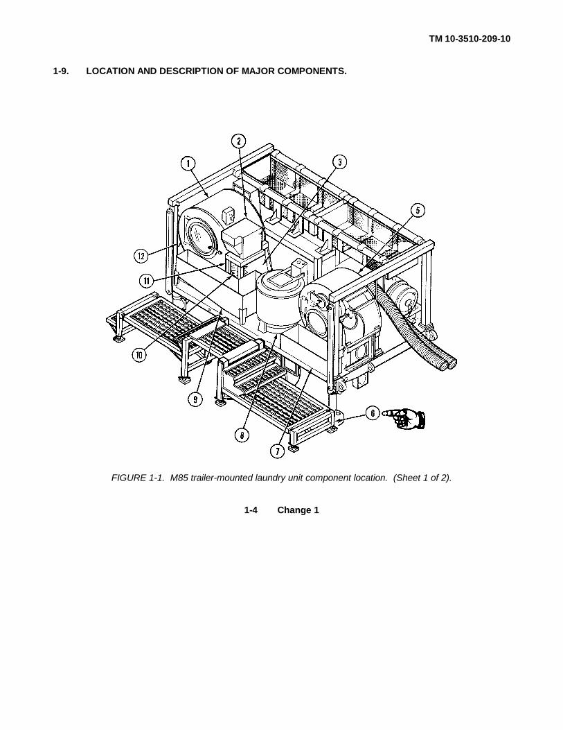
1-9. LOCATION AND DESCRIPTION OF MAJOR COMPONENTS.
FIGURE 1-1. M85 trailer-mounted laundry unit component location. (Sheet 1 of 2).
1-4 Change 1

TM 10-3510-209-10
1-9. LOCATION AND DESCRIPTION OF MAJOR COMPONENTS. (CONT)
FIGURE 1-1. M85 Trailer Mounted Laundry Unit component location. (Sheet 2 of 2)
Change 1 1-5

TM 10-3510-209-10
1-9. LOCATION AND DESCRIPTION OF MAJOR COMPONENTS. (CONT)
1 WASHER. Washer (1, FIG. 1-1) is an open-end loader, reversible-type cylinder. The washer washessoiled clothes and linen during the wash cycle.
2 CONTROLLER. Controller controls the operations of the washer assembly.
3 CIRCUIT BREAKER BOX. Circuit breaker box is located behind control stand (11) and provides safetycutouts for electrical circuits.
4 Deleted.
5 DRYER. Dryer assembly is an open-end, nonreversible-type cylinder. The dryer dries the clothes afterthey are removed from the extractor.
6 PLATFORM. Platform provides the operator with a place to stand and walk while operating the laundryunit.
7 DRYER BIN. Dryer bin provides a holding place for the dry clothes after they are removed from thedryer. During transport, the dryer bin is stored on the right-hand side of the trailer.
8 EXTRACTOR. Extractor is a heavy-duty, top-loading-type cylinder. It removes excess water from theclothes before they are placed in the dryer.
9 PRE-EXTRACTION BIN. Pre-extraction bin provides a holding place for the wet clothes before they areplaced in the extractor.
10 AIR COMPRESSOR. Air compressor provides air pressure for the operation of the water valves.
11 CONTROL STAND. Control stand is the housing for the controller and compressor.
12 FIRE EXTINGUISHER. Portable fire extinguisher is provided for emergency use in case of fire.
13 WATER HEATER. Water heater heats incoming water to desired temperatures as needed for thewasher.
14 HOSE BASKET ASSEMBLY. Hose basket assemblies provide storage for hoses, heater ducts, andother equipment.
15 Deleted.
16 WATER PUMP. Water pump provides the necessary water needed for the laundry unit.
16.1 LADDER. Ladder assists operator in reaching hose baskets.
17 SOUND DEADENING PANELS. Sound deadening panels shield the operator from generator noise.
18 GENERATOR. Generator provides electrical power to major components of the laundry unit.
1-6 Change 1
TM 10-3510-209-10
1-10. EQUIPMENT DATA.
a. Laundry Unit.
Model number ............................ M85Length........................................ 18 ft 2 in. (5.54 m)Height ........................................ 7 ft 10 in. (2.39 m)Width ......................................... 8 ft (2.44 m)Weight ....................................... 12,860 lb (5838 kg)Power Requirements.................. Class L, 60 amps, 208/220 V ac, 3-phaseFuel Requirements..................... Diesel fuel (item 10, app C)
b. Open-End Washer.
Model Number ........................... 360 EW/ACJMaximum speed......................... 33 rpmCapacity..................................... 60 lb (27 kg)Water Pressure Required ........... 10 psi (69 kPa) minimum, 75 psi (517 kPa)
maximumAir Pressure Required ................ 30 psi (207 kPa) minimum, 110 psi (758 kPa)
maximumVolts........................................... 208 V acPhase......................................... 3Frequency.................................. 60 HzAmps ......................................... 7.6 ampsPower rating............................... 1.5 hp (1 119 W)Motor speed ............................... 1725 rpm
c. Extractor.
Maximum speed......................... 1725 rpmCapacity..................................... 30 lb (14 kg)Volts........................................... 208/220 V acPhase......................................... 3Frequency.................................. 60 HzAmps ......................................... 9.3 ampsPower rating............................... 3 hp (2 238 W)Motor speed ............................... 1750 rpm
d. Dryer.
(1) Burner Blower and Fuel Pump Motor
Volts........................................... 208/220 V acPhase......................................... 3Frequency.................................. 60 HzAmps ......................................... 2.1 ampsPower rating............................... 1/2 hp (373 W)Motor speed ............................... 3450 rpm
1-7

TM 10-3510-209-10
1-10. EQUIPMENT DATA. (CONT)
(2) Tumbler Cylinder Motor
Volts........................................... 208 V acCapacity..................................... 30 lb (14 kg)Phase......................................... 3Frequency.................................. 60 HzAmps ......................................... 2.1 ampsPower rating............................... 1/2 hp (373 W)Motor speed ............................... 1725 rpm
(3) Tumbler Exhaust Motor
Volts........................................... 208 V acPhase......................................... 3Frequency.................................. 60 HzAmps ......................................... 2.2 ampsPower rating............................... 1/2 hp (373 W)Motor speed ............................... 1725 rpm
e. Air Compressor.
Volts........................................... 208 V acPhase......................................... 3Frequency.................................. 60 HzAmps ......................................... 2.2 ampsPower rating............................... 1/2 hp (373 W)Motor speed ............................... 1725 rpm
f. Water Heater
Fuel Pump Pressure................... 0 to 150 psi (1 034 kPa)
Burner Blower Fuel Pump Motor
Volts........................................... 208 V acPhase......................................... 3Frequency.................................. 60 HzPower rating............................... 1/3 hp (249 W)Motor speed ............................... 3450 rpm
g. Water Pump.
Type........................................... Centrifugal, self-priming after initialprime;Capacity .................... 18-20 gpm (68-76 liters/minute) at 65-foot
(19.8 m) head
1-8

TM 10-3510-209-10
1-10. EQUIPMENT DATA. (CONT)
Pump Motor
Volts ................................ ................................ ................ 208 V acPhase................................ ................................ ................ 3Frequency................................ ................................ ......... 60 HzAmps ................................ ................................ ................ 3.1/1.0 ampsPower rating................................ ................................ ...... 3/4 hp (560 W)Motor speed ................................ ................................ ...... 3450 rpm
SECTION III. TECHNICAL PRINCIPLES OF OPERATION
Para Title Page
1-11 Introduction................................ ................................ ................................ ............. 1-91-12 Washer ................................ ................................ ................................ ............... 1-91-13 Extractor ................................ ................................ ................................ ............... 1-101-14 Dryer ................................ ................................ ................................ ............... 1-101-15 Water Heater................................ ................................ ................................ .......... 1-101-16 Water Pump ................................ ................................ ................................ ........... 1-101-17 Air Compressor................................ ................................ ................................ ....... 1-101-18 Generator and Power Distribution Box................................ ................................ .... 1-10
1-11. INTRODUCTION . The laundry system consists of seven functional systems:
a. Washing system
b. Extracting system
c. Drying system
d. Water heating system
e. Water pumping system
f. Air compressor system
g. Generator/power distribution system
1-12. WASHER.
The heavy-duty washer is powered by an externally-mounted motor, drive train, and control unit. The washer iscontrolled either automatically or manually and has a 60-pound (27 kg) capacity. Two 60-pound (27 kg) loadscan be washed per hour in the automatic mode. Automatic operation is provided by a control unitprogrammable to regulate all functions of the laundry cycle. These functions are the number of washes andrinses, water level, and water temperature. Charts used to operate the controller are pre-punched with standardcycles. Manual operation has a variable wash time of up to 30 minutes.
1-9

TM 10-3510-209-10
1-13. EXTRACTOR.
The extractor uses centrifugal force to extract water from the wash load prior to the drying process. It ispowered by a 3-hp (2 238 W) motor. The extractor control has a 10-minute variable timer and has a loadcapacity of 30 pounds (14 kg).
1-14. DRYER.
The heavy-duty dryer is powered by an externally-mounted 1/2 hp (373 W) motor and drive train. It has acapacity of 30 pounds (14 kg) per load, approximately four loads per hour. Controls provide for an adjustablerange of 15 minutes for the drying cycle. Air is heated by a fuel-fired air heater mounted on the dryer.
1-15. WATER HEATER.
The water heater heats incoming water for the washer assembly.
1-16. WATER PUMP.
The portable, centrifugal-type water pump is mounted in a carrying frame. The pump is stored on the right frontside of the trailer during transport. During use, it is placed near the water source and connected to the facilityby a water output hose and power cable. After the initial prime, the pump will deliver 18 to 20 gallons (68 to 76liters) of water per minute.
1-17. AIR COMPRESSOR.
The air compressor provides air pressure for the operation of washer water intake and drain valves. Theadjustable range of compressed air is 20 to 80 psi (138 to 552 kPa).
1-18. GENERATOR AND POWER DISTRIBUTION BOX .
The generator is mounted on the right-hand side of the trailer. Refer to TM 5-6115-585-12 for generaldescription. The laundry unit operates on 60-Hertz, 3-phase, 208 V ac power. An electrical panel providespower distribution from the engine generator to the components of the laundry facility. The panel includes thenecessary circuit breakers for powering facility components.
1-10

TM 10-3510-209-10
CHAPTER 2
OPERATING INSTRUCTIONS
SECTION I. DESCRIPTION AND USE OF OPERATOR'S CONTROLS AND INDICATORS
Para Title Page
2-1 Introduction ................................ ................................ ................................ ............... 2-12-2 Location and Use of Controls and Indicators ................................ .............................. 2-1
2-1. INTRODUCTION .
This section shows the location and describes the use ofcontrols and indicators you will use in operating your equipment.
2-2. LOCATION AND USE OF CONTROLS AND INDICATORS.
a. You should know the location and proper use of every control and indicator before operating thelaundry unit. Use this section to learn or refresh your memory about each control and indicator andhow it works.
b. Refer to TM 5-6115-585-12, Generator Set, Diesel Engine Driven, 10kW, 60 Hz, for generatorcontrols and indicators.
c. For locations and functions of the controls and indicators on the laundry unit, refer to the followingfigures.
Controls/Indicators Figure
Washer System................................ ........................... 2-1Dryer System ................................ .............................. 2-2Extractor System................................ ......................... 2-3Water Heater ................................ .............................. 2-4DeletedWater Pump................................ ................................ 2-6Circuit Breakers ................................ .......................... 2-7Compressed Air System................................ .............. 2-8
Change 1 2-1

TM 10-3510-209-10
2-2. LOCATION AND USE OF CONTROLS AND INDICATORS. (CON’T)
Figure 2-1. Washer system controls and indicators.
2-2

TM 10-3510-209-102-2. LOCATION AND USE OF CONTROLS AND INDICATORS. (CONT)
Key Control or Indicator Function/Use
1 Temperature Gage Indicates temperature of water coming from
water heater
2 Float Level Controls amount of water allowed inside
cylinder
3 1 5-Amp Fuses Protects the 240 V circuit
4 10-Amp Fuses Protects the 240 V circuit
5 Timer Control Controls time of operation during manual
operation
6 ENABLED POSITION Switch Activates signal indicator light during
manual operation
7 DRAIN REUSE Switch Not used (nonfunctional)
8 SIGNAL Indicator Light Alerts operator that attention is required at
the washer controls
9 COLD WATER Switch Turns cold water valve on/off
10 HOT WATER Switch Turns hot water valve on/off
11 WATER LEVEL Switch Selects high and low water levels
12 DRAIN Switch Opens and closes drain valve
13 SIGNAL Cancel Switch Cancels signal indicator light
14 CONTROL NO 2 Switch Not used (nonfunctional)
15 TEMPERATURE NO 1 Switch Not used (nonfunctional)
16 MOTOR Switch Turns drive motor on/off
17 MASTER Switch Turns controller on/off and operates chart
drive motor
18 TIMER Indicator Light Indicates machine is on and cylinder is
advancing during automatic operation
19 Interior Light Indicates to operator that power is on and
unit is in operation
20 Door Latch Provides access to washer drum
21 Control Knob Manually advances cylinder
22 Reset Button Resets motor circuit breaker
23 Soap Chute Allows operator to add supplies during the
washing cycle.
Change 2 2-3

TM 10-3510-209-102-2. LOCATION AND USE OF CONTROLS AND INDICATORS. (CON’T)
Figure 2-2. Dryer system controls and indicators.
2-4

TM 10-3510-209-102-2. LOCATION AND USE OF CONTROLS AND INDICATORS. (CONT)
Key Control or Indicator Function/Use
1 Fuel Pressure Gage Indicates pressure of fuel to burner.
2 Burner-Air Intake Controls amount of air to burner.
a. Turned downward, increases air to burner.
b. Turned upward, decreases air to burner.
3 Door Limit Switch Stops tumbler rotation when dryer door is
opened.
4 Electric Timer Controls drying time.
5 Start/Stop Buttons Starts and stops blower motor and turns
ignition on and off.
6 Buzzers Alerts operator that a safety shutdown has
occurred.
7 UV Scanner Indicator light Gives visual indication that a safety shutdown
has occurred.
8 Exhaust Temperature Gage Indicates temperature of drying air inside
tumbler.
9 Temperature Control Controls temperature inside of tumbler.
10 Tumbler Burner Sight Glass To observe flame inside the burner.
11 Air Shutter Allows operator to fine-tune air fuel mixture.
12 Burner Fuel Shutoff Valve Opens and closes fuel supply to burner.
2-5
TM 10-3510-209-102-2. LOCATION AND USE OF CONTROLS AND INDICATORS. (CONT)
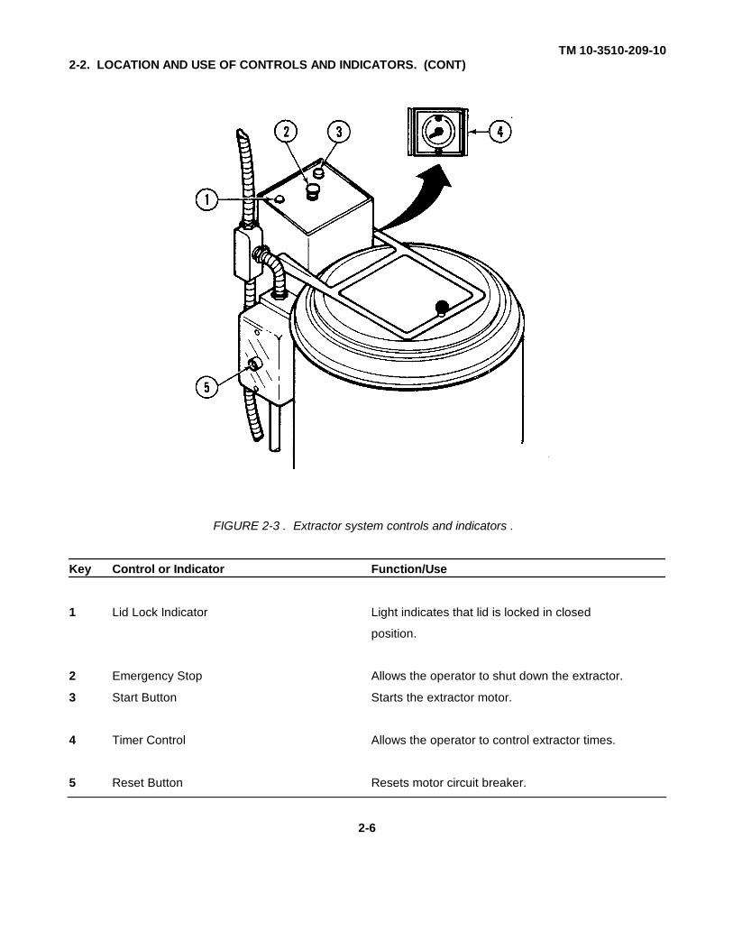
FIGURE 2-3 . Extractor system controls and indicators .
Key Control or Indicator Function/Use
1 Lid Lock Indicator Light indicates that lid is locked in closed
position.
2 Emergency Stop Allows the operator to shut down the extractor.
3 Start Button Starts the extractor motor.
4 Timer Control Allows the operator to control extractor times.
5 Reset Button Resets motor circuit breaker.
2-6
TM 10-3510-209-10
2-2. LOCATION AND USE OF CONTROLS AND INDICATORS. (CONT)
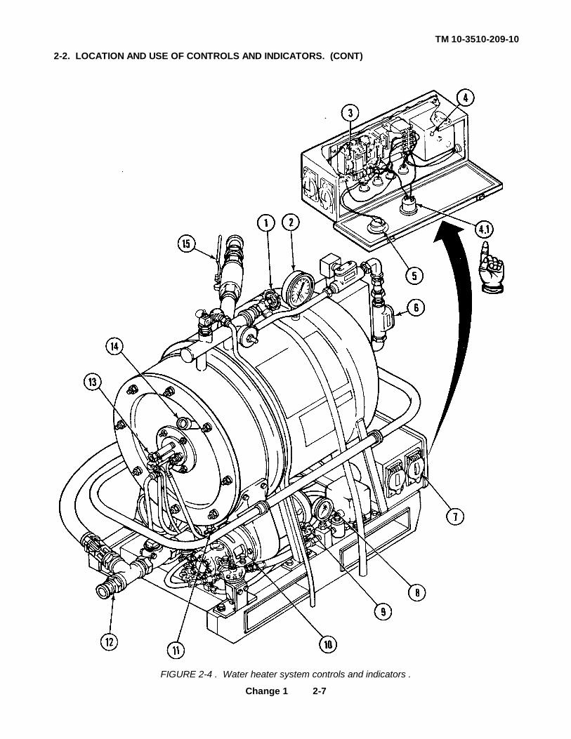
FIGURE 2-4 . Water heater system controls and indicators .
Change 1 2-7

TM 10-3510-209-102-2. LOCATION AND USE OF CONTROLS AND INDICATORS. (CONT)
Key Control or Indicator Function/Use
1 Vent Valve Allows the operator to bleed air from water
heater
2 Water Temperature Gage Indicates temperature of water being supplied
to the washer assembly
3 Motor Contactor Reset Over current reset devices that break the
circuit to the blower motor, if motor input
leads are overloaded
4 Flame Safeguard Control Lockout switch for flame safeguard control
Reset system When pressed, resets electrical
circuit to allow ignition in water heater
combustion chamber
4.1 Buzzer Alerts the operator that his/her attention is
needed at the water heater controls
5 Hour Meter Indicates length of time that burner has been
in operation
6 Water Temperature Control A calibrated dial to set the desired outlet
water temperature between 0° and 250°F (-18 and
+121°C) Operates burner to maintain outlet
water temperature between 182° and 2100F (83
and 990C)
7 Load Limit Switch Single-throw switch used to disconnect power to
(Water Heater Switch) motor, ignition transformer, and all electrical
controls on water heater
8 Fuel Pressure Gage Registers pressure of fuel being supplied to
burner
9 Manual Fuel Shutoff Valve Starts and stops flow of fuel to burner
a. Valve turned clockwise closes valve and
stops flow of fuel to burner
b. Valve turned counterclockwise opens valve
and starts flow of fuel to burner
10 Blower Shutter Increases or decreases amount of air to burner
a. Shutter turned downward increases amount of
air to burner
b. Shutter turned upward decreases amount of
air to burner
Change 1 2-8
TM 10-3510-209-102-2. LOCATION AND USE OF CONTROLS AND INDICATORS. (CONT)
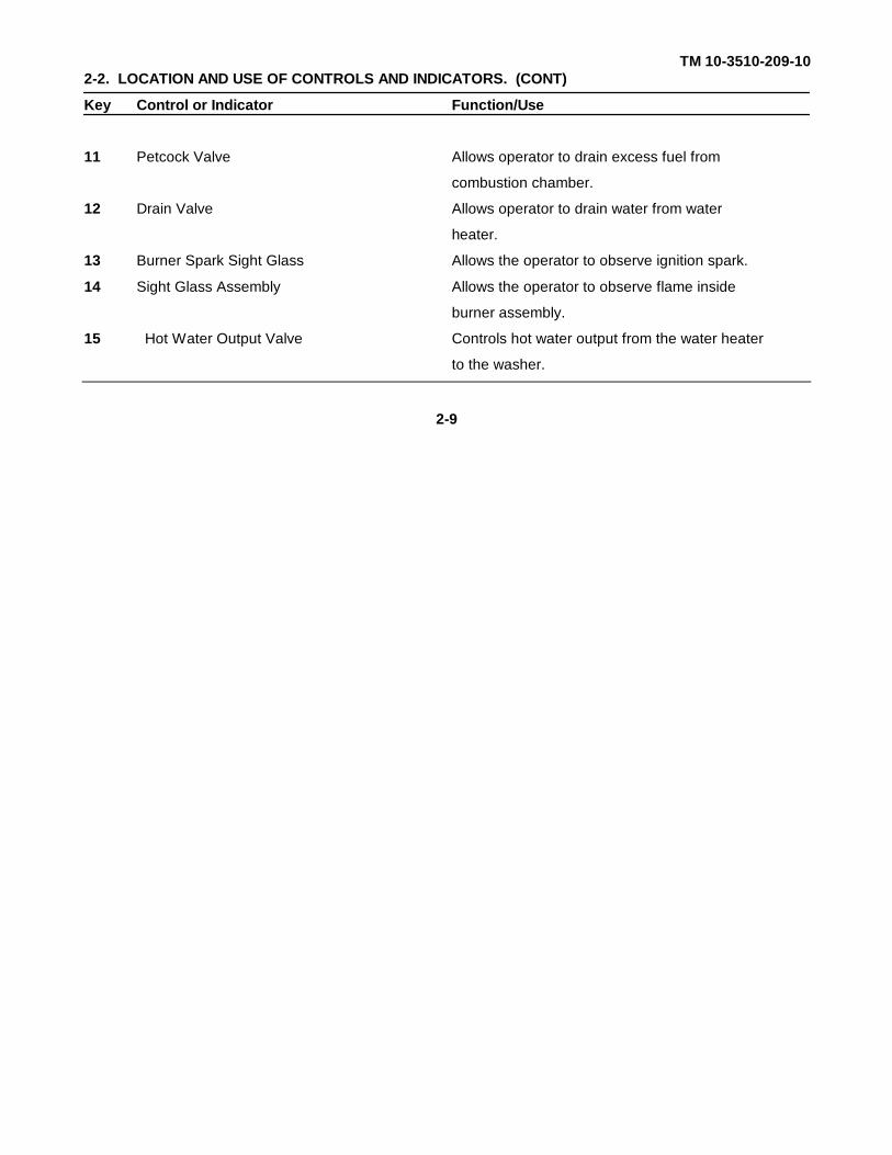
Key Control or Indicator Function/Use
11 Petcock Valve Allows operator to drain excess fuel from
combustion chamber.
12 Drain Valve Allows operator to drain water from water
heater.
13 Burner Spark Sight Glass Allows the operator to observe ignition spark.
14 Sight Glass Assembly Allows the operator to observe flame inside
burner assembly.
15 Hot Water Output Valve Controls hot water output from the water heater
to the washer.
2-9

TM 10-3510-209-10
"All data on page 2-10, including figure 2-5 deleted."
Change 1 2-10

TM 10-3510-209-102-2. LOCATION AND USE OF CONTROLS AND INDICATORS. (CONT)
FIGURE 2-6 . Water pump system controls and indicators .
Key Control or Indicator Function/Use
1 Start Switch Turns water pump on or off.
2 Deleted
3 Petcock Valve Allows the operator to drain water from water
pump.
Change 1 2-11
TM 10-3510-209-102-2. LOCATION AND USE OF CONTROLS AND INDICATORS. (CONT)
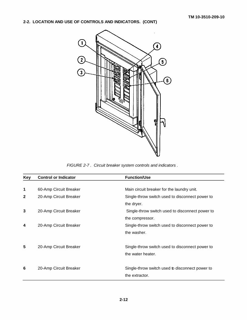
FIGURE 2-7 . Circuit breaker system controls and indicators .
Key Control or Indicator Function/Use
1 60-Amp Circuit Breaker Main circuit breaker for the laundry unit.
2 20-Amp Circuit Breaker Single-throw switch used to disconnect power to
the dryer.
3 20-Amp Circuit Breaker Single-throw switch used to disconnect power to
the compressor.
4 20-Amp Circuit Breaker Single-throw switch used to disconnect power to
the washer.
5 20-Amp Circuit Breaker Single-throw switch used to disconnect power to
the water heater.
6 20-Amp Circuit Breaker Single-throw switch used to disconnect power to
the extractor.
2-12
TM 10-3510-209-102-2. LOCATION AND USE OF CONTROLS AND INDICATORS. (CONT)
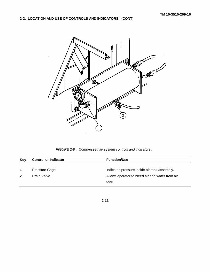
FIGURE 2-8 . Compressed air system controls and indicators .
Key Control or Indicator Function/Use
1 Pressure Gage Indicates pressure inside air tank assembly.
2 Drain Valve Allows operator to bleed air and water from air
tank.
2-13
TM 10-3510-209-10
SECTION II. PREVENTIVE MAINTENANCE CHECKS AND SERVICES (PMCS)
Para Title Page
2-3 Introduction ................................ ................................ ................................ ............... 2-142-4 General Maintenance Procedures................................ ................................ ................. 2-162-5 Operator/Crew Preventive Maintenance Checks and Services Table............................ 2-16
2-3. INTRODUCTION.
a. General. Your preventive Maintenance Checks and Services table lists the inspections and careyour equipment requires to keep it in good operating condition.
(1) Before you operate - Always keep in mind the CAUTIONS and WARNINGS. Perform yourbefore (B) PMCS.
(2) While you operate - Always keep in mind the CAUTIONS and WARNINGS. Perform yourduring (D) PMCS.
(3) After you operate - Be sure to perform your after (A) PMCS.(4) If your equipment fails to operate - If your equipment does not perform as required, refer to
chapter 3 under Troubleshooting for possible problems. Report any malfunctions or failureson the proper DA Form 2404, or refer to DA PAM 738-750.
b. PMCS Columnar Entries.
(1) Item number column. This is the order in which you perform checks and services on thelaundry unit. The entry in this column will also be used as a source of item numbers for theTM Item Number column on DA Form 2404, Equipment Inspection and MaintenanceWorksheet, in recording results of PMCS.
(2) Interval column. The Interval column of your PMCS table tells you when to do a certaincheck or service.
(3) Item to be Inspected column. Identification of item to be inspected.
(4) Procedures column. The Procedures column of your PMCS table tells you how to do therequired checks and services. Carefully follow these instructions. If you do not have thetools, or if the procedure tells you to, have the next higher level of maintenance do the work.
2-14

TM 10-3510-209-10
2-3. INTRODUCTION. (CONT)
(5) Equipment Is Not Ready/Available If column. Entries in this column will be keyed specificallyto checks listed in the Procedures column for the purpose of identifying, for the check, thecriteria that will cause the equipment to be classified as not ready/available because ofinability to perform its primary Combat Mission. An entry in this column will:
(a) Identify conditions that make the equipment not ready/available for readiness reporting.
(b) Deny use of the equipment until corrective maintenance has been performed.
c. Special Instructions.
(1) Perform Weekly (W) as well as Before operations PMCS if:
(a) You are the assigned operator and have not operated the item since the last weekly.
(b) You are operating the item for the first time.
(2) Leakage definitions for operator/crew PMCS shall be classified as follows:
NOTE
Equipment operation is allowable with minor leakage (Class I or II). Of course, youmust consider the fluid capacity in the item/system being checked/inspected.When in doubt, notify your supervisor.
NOTE
When operating with Class I or II leaks, continue to check fluid levels as requiredin your PMCS.
NOTE
Class III leaks should be reported to your supervisor.
(a) Class I. Seepage of fluid (as indicated by wetness or discoloration) not great enough toform drops.
(b) Class II. Leakage of fluid great enough to form drops but not enough to cause drops todrip from item being checked/inspected.
(c) Class III. Leakage of fluid great enough to form drops that fall from the item beingchecked/inspected.
2-15
TM 10-3510-209-10
2-4. GENERAL MAINTENANCE PROCEDURES .
As you perform your PMCS, keep in mind the following:
a. Cleanness. Dirt, grease, oil, and debris only get in the way and may cover up a serious problem.b. Bolts, Nuts, and Screws. Check them all for obvious looseness and missing, bent, or broken
condition. You cannot try them all with a tool, of course, but look for chipped paint, bare metal, orrust around bolt heads. If you find one you think is loose, report it to your supervisor.
c. Welds. Look for loose or chipped paint, rust, or gaps where parts are welded together. If you finda bad weld, report it to your supervisor.
d. Electrical Wires and Connections. Look for cracked or broken insulation, bare wires, and loose orbroken connectors. Tighten loose connections and make sure the wires are in good condition. Ifyou find a bad wire or connector, report it to your supervisor.
e. Water Lines and Fittings. Look for wear, damage, and leaks. Make sure clamps and fittings aretight. Wet spots show leaks, but a stain around a fitting or connector can mean a leak. If a leakcomes from a loose fitting or connector, or if something is broken or worn out, report it to yoursupervisor.
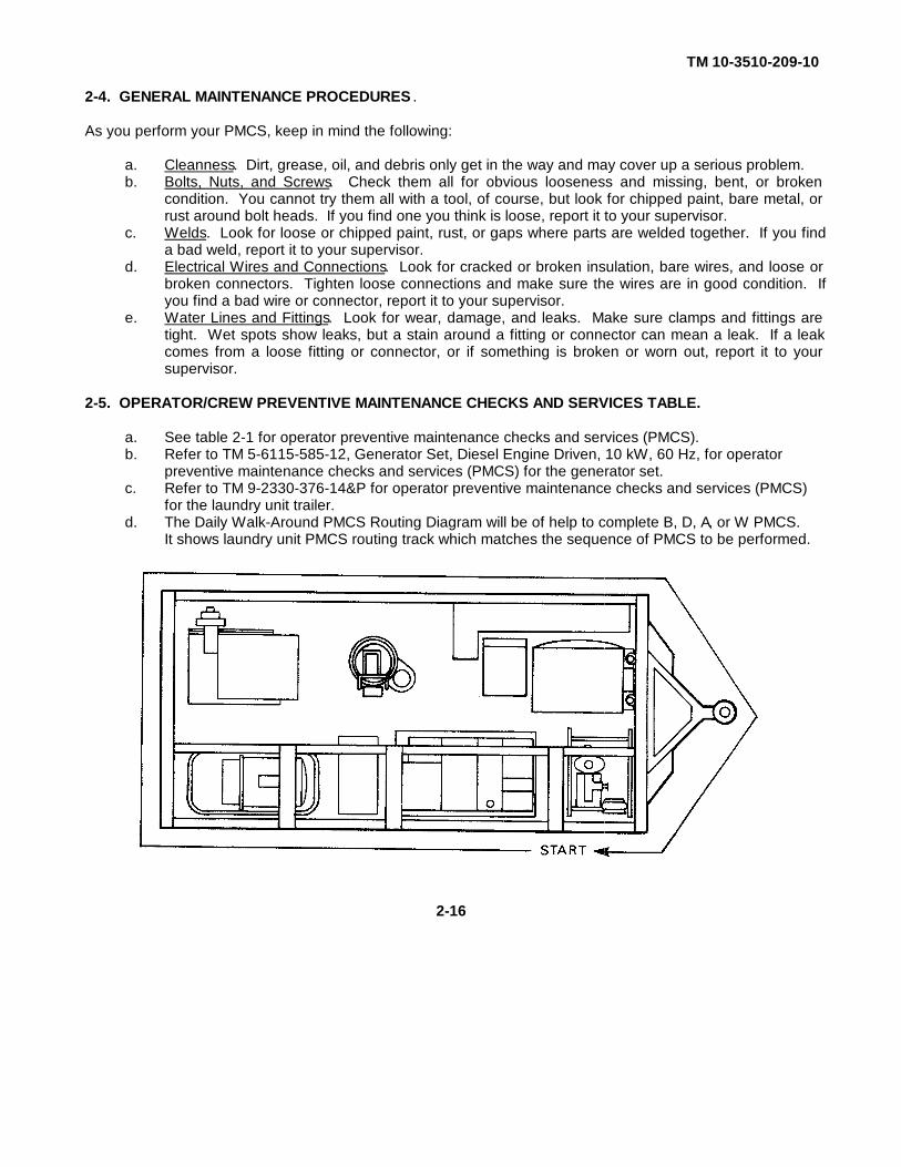
2-5. OPERATOR/CREW PREVENTIVE MAINTENANCE CHECKS AND SERVICES TABLE.
a. See table 2-1 for operator preventive maintenance checks and services (PMCS).b. Refer to TM 5-6115-585-12, Generator Set, Diesel Engine Driven, 10 kW, 60 Hz, for operator
preventive maintenance checks and services (PMCS) for the generator set.c. Refer to TM 9-2330-376-14&P for operator preventive maintenance checks and services (PMCS)
for the laundry unit trailer.d. The Daily Walk-Around PMCS Routing Diagram will be of help to complete B, D, A, or W PMCS.
It shows laundry unit PMCS routing track which matches the sequence of PMCS to be performed.
2-16

TM 10-3510-209-10
Table 2-1. Operator/Crew Preventive Maintenance Checks and Services
NOTE
Within the designated interval, these checks are to be performed in the orderlisted.
B-Before D-During A-After W-WeeklyProcedures: Equipment Is
Item Interval Item To Be Check for and have repaired Not Ready/No. B D A W Inspected filled, or adjusted as needed. Available If:
NOTE
Perform lubrication prior to or in conjunc-tion with your PMCS. Refer to LO 10-3510-209-12.
1 WATER PUMP
Electric motor (1): Inspect Motor isfor obstruction to ventilation and loose.for loose mounting.
Change 1 2-17

TM 10-3510-209-10
Table 2-1. Operator/Crew Preventive Maintenance Checks and Services(Continued)Procedures: Equipment Is
Item Interval Item To Be Check for and have repaired Not Ready/No. B D A W Inspected filled, or adjusted as needed. Available If:
2 GENERATOR
a. Remove large sound deadeningpanel (1.1) and perform generator PMCS.Refer to TM 5-6115-585-12.
b. Remove protective coveron top of batteries and performPMCS. Refer to TM 5-6115-585-12.
Change 1 2-18

TM 10-3510-209-10Table 2-1. Operator/Crew Preventive Maintenance Checks and Services (Continued)
Procedures: Equipment IsItem Interval Item To Be Check for and have repaired Not Ready/No. B D A W Inspected filled, or adjusted as needed. Available If:
3 WATERHEATER
a. Fuel shutoff valve (2): Place There is catch-valve in the open position and ing or bindingcheck for catching or binding. during rotation.
Clockwise rotation closesvalve.
Counterclockwise rotationopens valve.
b. Ignition cables (3): Inspect Cables arefor crushed, broken, and loose crushed orcables. Secure loose cables. broken.
c. Sight glass assembly (4) and Glass is brokencombustion sight glass assembly or missing.(5): Inspect for broken or miss-ing glass. Ensure sight glassassembly is secure and clean.
d. Bleeder valve hose (6): Hose is missing.Inspect hose to see if it is looseor missing.
2-19
TM 10-3510-209-10Table 2-1. Operator/Crew Preventive Maintenance Checks and Services (Continued)
Procedures: Equipment IsItem Interval Item To Be Check for and have repaired Not Ready/No. B D A W Inspected filled, or adjusted as needed. Available If:
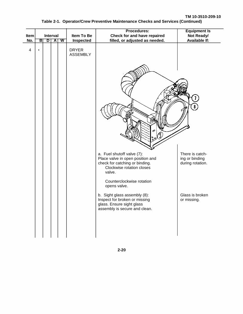
4 • DRYERASSEMBLY
a. Fuel shutoff valve (7): There is catch-Place valve in open position and ing or bindingcheck for catching or binding. during rotation.
Clockwise rotation closesvalve.
Counterclockwise rotationopens valve.
b. Sight glass assembly (8): Glass is brokenInspect for broken or missing or missing.glass. Ensure sight glassassembly is secure and clean.
2-20

TM 10-3510-209-10Table 2-1. Operator/Crew Preventive Maintenance Checks and Services (Continued)
Procedures: Equipment IsItem Interval Item To Be Check for and have repaired Not Ready/No. B D A W Inspected filled, or adjusted as needed. Available If:
5 • WASHERASSEMBLY
a. Controller assembly (9): Window is miss-Inspect controller window for in or broken.broken or missing glass.Clean glass as necessary.
b. Washer door assembly (10): Glass is miss-Inspect glass and seal for ing or broken.cracks, breaks, and missingglass.
2-21

TM 10-3510-209-10Table 2-1. Operator/Crew Preventive Maintenance Checks and Services (Continued)
Procedures: Equipment IsItem Interval Item To Be Check for and have repaired Not Ready/No. B D A W Inspected filled, or adjusted as needed. Available If:
6 FIREEXTINGUISHER
a. Inspect fire extinguisher pin(11) for damaged or missingcondition.
Inspect pressure gage (12) Fire extin-for indication of being fully guisher notcharged. fully charged.
2-22

TM 10-3510-209-10Table 2-1. Operator/Crew Preventive Maintenance Checks and Services (Continued)
Procedures: Equipment IsItem Interval Item To Be Check for and have repaired Not Ready/No. B D A W Inspected filled, or adjusted as needed. Available If:
7· • WATERHEATER
a. Gages: After starting waterheater, check for thefollowing:
1. Temperature gage (13): Gage is brokenNormal indication 95 to or indicating160°F (35 to 710C) above 160°F
(71°C) or below2. Fuel pressure gage (14): 95OF (350C).
Normal indication 75 to80 psi (517 to 552 kPa)
2-23
TM 10-3510-209-10Table 2-1. Operator/Crew Preventive Maintenance Checks and Services (Continued)
Procedures: Equipment IsItem Interval Item To Be Check for and have repaired Not Ready/No. B D A W Inspected filled, or adjusted as needed. Available If:
7 (Cont)WARNING
Exhaust ducts become very hotduring operation. Wear protectivegloves when handling hot exhaustducts. Failure to wear protectivegloves could result in severe burns.
b. Exhaust duct (15): Visually Exhaust leaks.inspect exhaust duct for leaks.
c. Fuel pump, filter, and lines: Lines areInspect for fuel leaks and for leaking, kinked,kinked or crushed fuel lines. or crushed.
d. Water hoses and lines:Inspect for water leaks and forkinked or crushed hoses or lines.
2-24
TM 10-3510-209-10Table 2-1. Operator/Crew Preventive Maintenance Checks and Services (Continued)
Procedures: Equipment IsItem Interval Item To Be Check for and have repaired Not Ready/No. B D A W Inspected filled, or adjusted as needed. Available If:
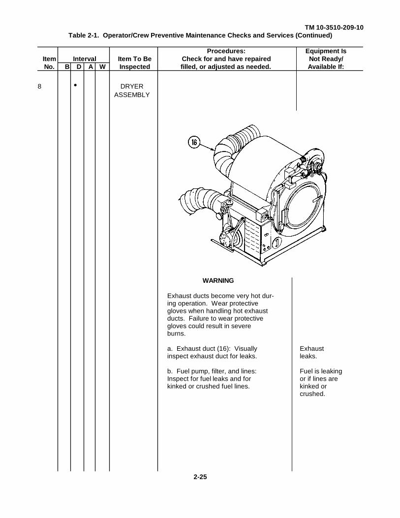
8 • DRYERASSEMBLY
WARNING
Exhaust ducts become very hot dur-ing operation. Wear protectivegloves when handling hot exhaustducts. Failure to wear protectivegloves could result in severeburns.
a. Exhaust duct (16): Visually Exhaustinspect exhaust duct for leaks. leaks.
b. Fuel pump, filter, and lines: Fuel is leakingInspect for fuel leaks and for or if lines arekinked or crushed fuel lines. kinked or
crushed.
2-25

TM 10-3510-209-10Table 2-1. Operator/Crew Preventive Maintenance Checks and Services (Continued)
Procedures: Equipment IsItem Interval Item To Be Check for and have repaired Not Ready/No. B D A W Inspected filled, or adjusted as needed. Available If:
9· • WATER PUMP
Petcock valve (17): Place valvein the open position to drainexcess water from the water pump.
Clockwise rotation closesvalve.Counterclockwise rotationopens valve.
Change 1 2-26
TM 10-3510-209-10Table 2-1. Operator/Crew Preventive Maintenance Checks and Services (Continued)
Procedures: Equipment IsItem Interval Item To Be Check for and have repaired Not Ready/No. B D A W Inspected filled, or adjusted as needed. Available If:
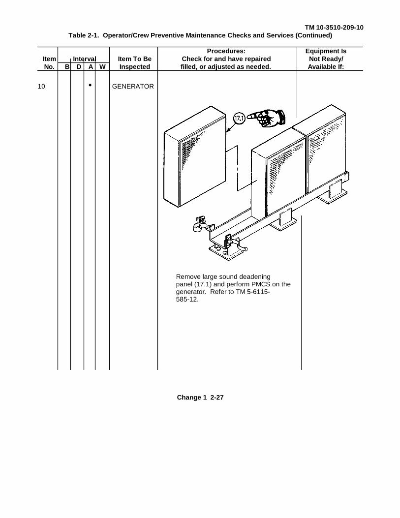
10 • GENERATOR
Remove large sound deadeningpanel (17.1) and perform PMCS on thegenerator. Refer to TM 5-6115-585-12.
Change 1 2-27

TM 10-3510-209-10Table 2-1. Operator/Crew Preventive Maintenance Checks and Services (Continued)
Procedures: Equipment IsItem Interval Item To Be Check for and have repaired Not Ready/No. B D A W Inspected filled, or adjusted as needed. Available If:
11 • WATERHEATER
a. Petcock valve (18): Place valvein open position to drain excessfuel from combustion chamber.
Clockwise rotation closesvalve.
Counterclockwise rotationopens valve.
b. Fuel filter (20): Refer toparagraph 3-7 and perform PMCSon water heater fuel filter.
2-28 Change 1

TM 10-3510-209-10Table 2-1. Operator/Crew Preventive Maintenance Checks and Services (Continued)
Procedures: Equipment IsItem Interval Item To Be Check for and have repaired Not Ready/No. B D A W Inspected filled, or adjusted as needed. Available If:
12 • DRYERHEATER
Fuel filter (21): Refer toparagraph 3-7 and perform PMCSon dryer fuel filter.
2-29

TM 10-3510-209-10
Section III. OPERATION UNDER USUAL CONDITIONS
Para Title Page2-6 Scope................................ ................................ ................................ ........................... 2-302-7 Site Selection, Setup, and Assembly................................ ................................ ............ 2-302-8 Preparation for Use ................................ ................................ ................................ ..... 2-472-9 Operating Procedures ................................ ................................ ................................ .. 2-622-10 Preparation for Movement ................................ ................................ ........................... 2-692-11 Operating Instructions on Decals and Instruction Plates ................................ ............... 2-74
2-6. SCOPE. This section contains procedures for operation of the laundry unit.
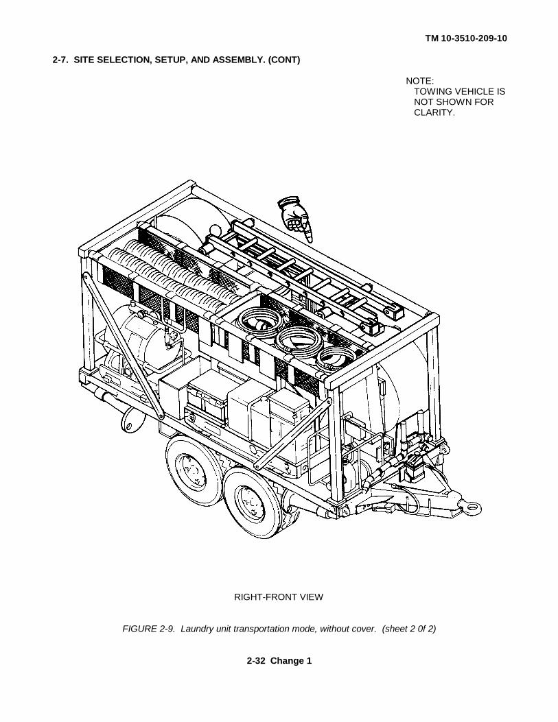
2-7. SITE SELECTION, SETUP, AND ASSEMBLY . Components are mounted or stored on the trailer forshipment and storage. During use, some components are removed from the trailer. The setup instructions thatfollow include steps for unpacking and positioning components. Components should be unpacked only whenthe facility is planned for use or when maintenance is needed. FIGURE 2-9 shows the laundry unit as it wouldbe for shipping or storage, without the cover.
a. Select a site for the laundry unit that has adequate water and drainage for operational needs.Select a relatively level area, approximately 75 square feet (6.97 sq m).
(1) Position the laundry unit so that the water heater is next to the water source.
(2) Set the handbrake lever, lower the trailer supports, and unhitch towing vehicle. If necessary, dig holes or block wheels to ensure the trailer is level. Refer to TM 9-2830-276-14&P.
(3) Remove tarp assembly and inspect it for cuts, frays, weather rot, and damage. If tarp assembly is damaged, notify your supervisor.
(4) Remove bottom bolts from transportation braces (1) on the left side of trailer assembly. Rotate transportation braces downward into the vertical position.
2-30 Change 1

TM 10-3510-209-10
2-7. SITE SELECTION, SETUP, AND ASSEMBLY. (CONT)
LEFT-REAR VIEW
FIGURE 2-9. Laundry unit transportation mode, without cover. (sheet 1 of 2)
Change 1 2-31
TM 10-3510-209-10
2-7. SITE SELECTION, SETUP, AND ASSEMBLY. (CONT)
NOTE:TOWING VEHICLE ISNOT SHOWN FORCLARITY.
RIGHT-FRONT VIEW
FIGURE 2-9. Laundry unit transportation mode, without cover. (sheet 2 0f 2)
2-32 Change 1
TM 10-3510-209-10
2-7. SITE SELECTION, SETUP, AND ASSEMBLY. (CONT)
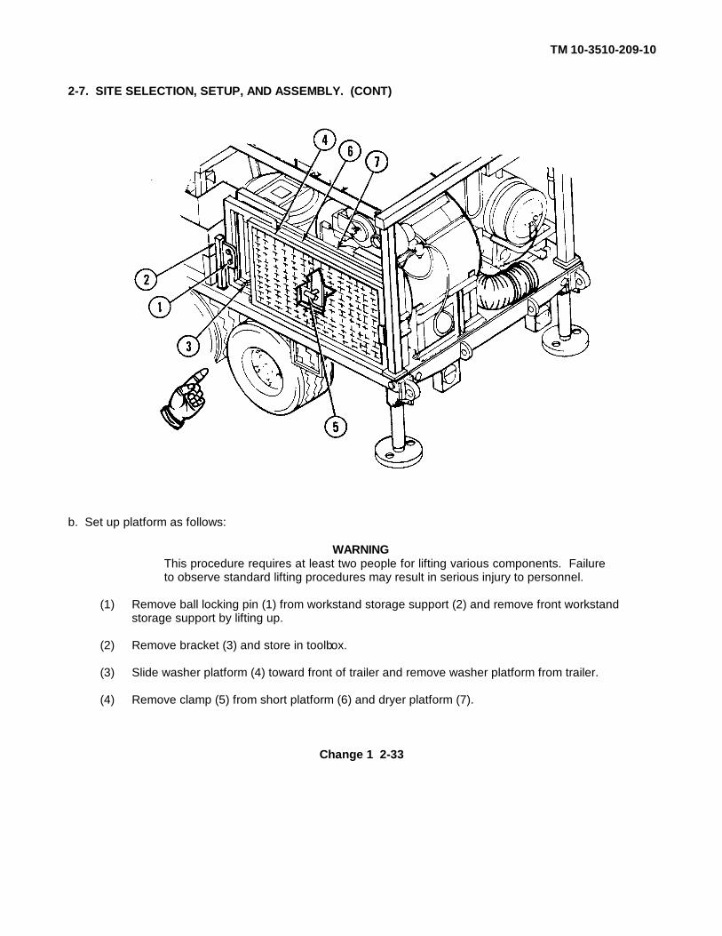
b. Set up platform as follows:
WARNINGThis procedure requires at least two people for lifting various components. Failureto observe standard lifting procedures may result in serious injury to personnel.
(1) Remove ball locking pin (1) from workstand storage support (2) and remove front workstandstorage support by lifting up.
(2) Remove bracket (3) and store in toolbox.
(3) Slide washer platform (4) toward front of trailer and remove washer platform from trailer. (4) Remove clamp (5) from short platform (6) and dryer platform (7).
Change 1 2-33
TM 10-3510-209-10
2-7. SITE SELECTION, SETUP, AND ASSEMBLY. (CONT)
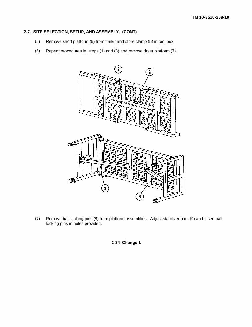
(5) Remove short platform (6) from trailer and store clamp (5) in tool box.
(6) Repeat procedures in steps (1) and (3) and remove dryer platform (7).
(7) Remove ball locking pins (8) from platform assemblies. Adjust stabilizer bars (9) and insert ball locking pins in holes provided.
2-34 Change 1
TM 10-3510-209-10
2-7. SITE SELECTION, SETUP, AND ASSEMBLY. (CONT)
(8) Place washer platform assembly (4) and dryer platform assembly (7) next to the trailer. Install short platform assembly (6). Remove two steps (11) from pre-extraction bin and install on platformassembly (4).
(9) Locate and remove step (10) from midsection of trailer and install step on dryer platform (7).
(10) Adjust leveling plates (12) and brace with footing platforms as needed.
Change 1 2-35
TM 10-3510-209-10
2-7. SITE SELECTION, SETUP, AND ASSEMBLY. (CONT)
(11) Unhook two straps (13) and remove ladder (14) from two struts (15).
(12) Remove four ball locking pins (16) from left beam (17) and center beam, (18) and remove twostruts (15).
(13) Remove two ball locking pins (19) from left beam (17) and remove left beam from frameassemblies (20) and (21). Store left beam underneath trailer.
2-36 Change 1
TM 10-3510-209-10
2-7. SITE SELECTION, SETUP, AND ASSEMBLY. (CONT)
(14) Position ladder (14) on right beam (22) as required.
(15) Remove contents from hose basket assemblies (23).
(16) Store tarp assembly, two struts, and workstand storage supports in hose basket assemblies (23).
c. Set up water pump and hose assembly as follows:
(1) Identify bracket assembly (1) which is located on the left-hand side of the water pump assembly.
Change 1 2-37

TM 10-3510-209-10
2-7. SITE SELECTION, SETUP, AND ASSEMBLY. (CONT)
(2) Remove two wingnuts (2) and remove bracket assembly (1).
(3) Remove water pump (3) and locate it no more than 10 feet (3 m) from the water source. (4) Install bracket (1) and tighten wingnuts (2) removed in step (2).
(5) Connect suction hose (1, FIG. 2-10) to suction inlet (2).
WARNING
Ensure that water hoses (1 and 4, FIG. 2-10) do not touch or cross otherwater hoses, exhaust ducts, power cables, or fuel lines. Melting/damage can occur causing leaking fuel and water or electical hazards.Death by electrocution, fire, or explosion could result.
(6) Connect suction strainer (3) to the other end of suction hose (1). Position the strainer in the water source above the stream bed. Make a tripod from tree branches or saplings and hang the strainer from the place where the branches are tied together, or position the strainer on a bed of stones or gravel.
(7) Connect water heater intake hose (4) to water pump discharge outlet (5).
(8) Connect the other end of water heater intake hose (4) to water heater inlet (6).
(9) Deleted
2-38 Change 1
TM 10-3510-209-10
2-7. SITE SELECTION, SETUP, AND ASSEMBLY. (CONT)
FIGURE 2-10. Water hose connection diagram.
Change 1 2-39

TM 10-3510-209-10
2-7. SITE SELECTION, SETUP, AND ASSEMBLY. (CONT)
(10) Ensure petcock valve (7) on water pump housing is closed. Clockwise rotation closes valve.
(11) Ensure petcock valve (8) and drain valve (9) on the water heater are closed. Clockwiserotation closes valve.
(12) Ensure washer inlet hose (10) is connected to washer inlet (11) and to water heater outlet(12).
(13) Ensure that hose (13) from water heater inlet (6) is connected to piping assembly (14).(14) Ensure that drain hose (1, FIG. 2-11) is connected to extractor drain connection (2) and
washer drain connection (3).
WARNING
Ensure that drain hoses (4 and 6, FIG. 2-11) do not touch or cross other waterhoses, power cables, exhaust ducts, or fuel lines. Melting/damage can occurcausing leaking fuel and water or electrical hazards. Death by electrocution, fire,or explosion could result.
(15) Connect one 25-foot (7.6 m), 1-1/2-inch-diameter drain hose (4) to pre-extraction bin drain(5) and route the hose to a drain field. Do not touch or cross other water hoses, powercables, exhaust ducts, or fuel lines.
(16) Connect one 25-foot (7.6 m), 2-1/2-inch-diameter drain hose (6) to washer drain (7) and routethe hose to a drain field. Do not touch or cross other water hoses, power cables, exhaustducts, or fuel lines.
d. Set up electric power cables as follows:
WARNING
The laundry unit uses 208 V ac. All circuit breakers on the electrical panel must beoff prior to connecting electrical power cables. Failure to observe safetyprecautions may result in death or serious injury.
(1) Open electrical panel door (1, FIG. 2-12) and turn off all circuit breakers (2).
(2) Remove dust cap (3) on main power connection (4).
Change 1 2-40
TM 10-3510-209-10
2-7. SITE SELECTION, SETUP, AND ASSEMBLY. (CONT)
(3) Connect main power cable (5) to main power connection (4). Connect other end of powercable to power source. Refer to TM 5-6115-585-12 for electrical connections on generator.
WARNING
Ensure that power cable (6, FIG. 2-12) does not touch or cross water hoses,exhaust ducts, or fuel lines. Melting/damage can occur causing leaking fuel andwater or electrical hazards. Death by electrocution, fire, or explosion could result.
NOTE
Lock power cables in place by rotating connector clockwise.
(4) Connect water pump cable (6) between water heater service outlet (7) and water pumpservice outlet (8). Do not touch or cross water hoses, exhaust ducts, or fuel lines.
(5) Ensure water pump ON/OFF switch is in the OFF position.
(6) Ensure water heater load limit switch is in the OFF position.
Change 1 2-40.1/(2-40.2 blank)

TM 10-3510-209-10
2-7. SITE SELECTION, SETUP, AND ASSEMBLY. (CONT)
FIGURE 2-11. Drain hose connection diagram.
2-41

TM 10-3510-209-10
2-7. SITE SELECTION, SETUP, AND ASSEMBLY. (CONT)
FIGURE 2-12. Electrical panel cable connection.
Change 1 2-42

TM 10-3510-209-10
2-7. SITE SELECTION, SETUP, AND ASSEMBLY. (CONT)
e. Remove and install dryer bin as follows:
(1) Remove four bolts (1, FIG. 2-13) located inside dryer bin (2).
(2) Remove dryer bin (2) and place it in front of dryer assembly (3).
(3) Install bolts (1) removed in step (1) in the same locations from which they were removed.
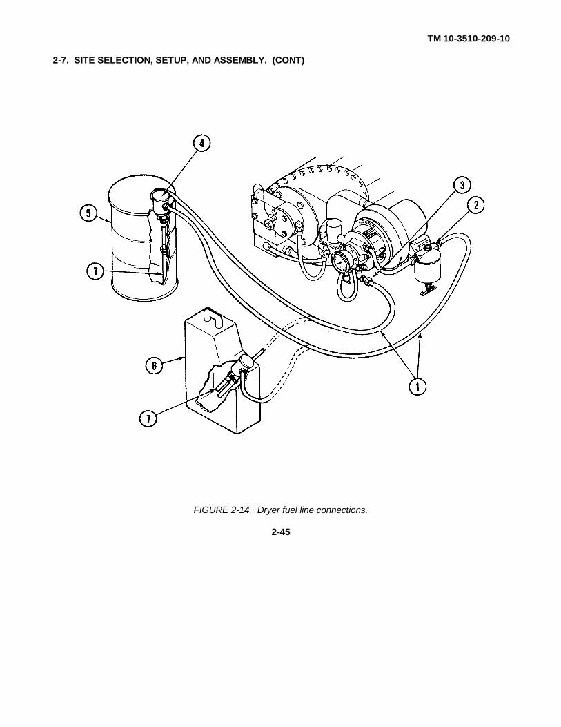
f. Make dryer fuel line connections as follows:
WARNING
Use only specified fuel (item 10, app C). Failure to do so may result in death orserious injury to personnel or damage to equipment.
(1) Obtain two fuel lines (1, FIG. 2-14).
WARNING
Ensure that fuel lines (1, FIG. 2-14) do not touch or cross water hoses, powercables, or exhaust ducts. Melting/damage can occur causing leaking fuel andwater or electrical hazards. Death by electrocution, fire, or explosion could result.
(2) Connect one fuel line (1) to fuel filter inlet (2) and one fuel line to fuel pump outlet (3).
(3) Connect the other ends of fuel lines (1) to drum fill adapter (4). The line from the fuel filterconnects to fitting labeled SUPPLY on drum fill adapter. The line from the bottom of fuelpump connects to fitting labeled RETURN on the drum fill adapter.
NOTE
The drum fill adapter can be used with 55-gallon (208 liter) drums (5), 5-gallon (19liter) cans (6), or other fuel sources.
(4) If a 55-gallon (208 liter) drum (5) is being used as the fuel source, remove drum fill adapterextension (7) from the bottom of the return port and install it in the drum fill adapter pipe.When using 5-gallon (19 liter) cans (6), the extension remains attached to the return port.
Change 1 2-43

TM 10-3510-209-10
2-7. SITE SELECTION, SETUP, AND ASSEMBLY. (CONT)
g. Make water heater fuel line connections as follows:
WARNING
Use only specified fuel (item 10, app C). Failure to do so may result in death orserious injury to personnel or damage to equipment.
(1) Obtain two fuel lines (1, FIG. 2-15).
WARNING
Ensure that fuel lines (1, FIG. 2-15) do not touch or cross water hoses, powercables, or exhaust ducts. Melting/damage can occur causing leaking fuel andwater or electrical hazards. Death by electrocution, fire, or explosion could result.
(2) Connect one fuel line (1) to fuel filter inlet (2) and one fuel line to fuel pump outlet (3).
FIGURE 2-13. Dryer bin removal and installation.
Change 1 2-44
TM 10-3510-209-10
2-7. SITE SELECTION, SETUP, AND ASSEMBLY. (CONT)
FIGURE 2-14. Dryer fuel line connections.
2-45

TM 10-3510-209-10
2-7. SITE SELECTION, SETUP, AND ASSEMBLY. (CONT)
FIGURE 2-15. Water heater fuel line connections.
2-46

TM 10-3510-209-10
2-7. SITE SELECTION, SETUP, AND ASSEMBLY. (CONT)
(3) Connect the other ends of fuel lines (1) to drum fill adapter (4). The line from the fuel filterconnects to fitting labeled SUPPLY on the drum fill adapter. The line from the bottom of fuelpump connects to fitting labeled RETURN on the drum fill adapter.
NOTE
The drum fill adapter can be used with 55-gallon (208 liter) drums (5), 5-gallon (19liter) cans (6), or other fuel sources.
(4) If a 55-gallon (208 liter) drum (5) is being used as the fuel source, remove drum fill adapterextension (7) from the bottom of the return port and install it in the drum fill adapter pipe.When using 5-gallon (19 liter) cans (6), the extension remains attached to the return port.
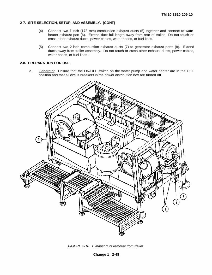
h. Make exhaust hose connections as follows:
WARNING
Carbon monoxide is dangerous. Ensure that exhausts are properly vented to anopen-air area. Death or serious injury to personnel can result from heavy exposureto exhaust gas.
(1) Unhook three straps (1, FIG. 2-16) and remove combustion exhaust ducts(2) from trailer assembly (3).
WARNING
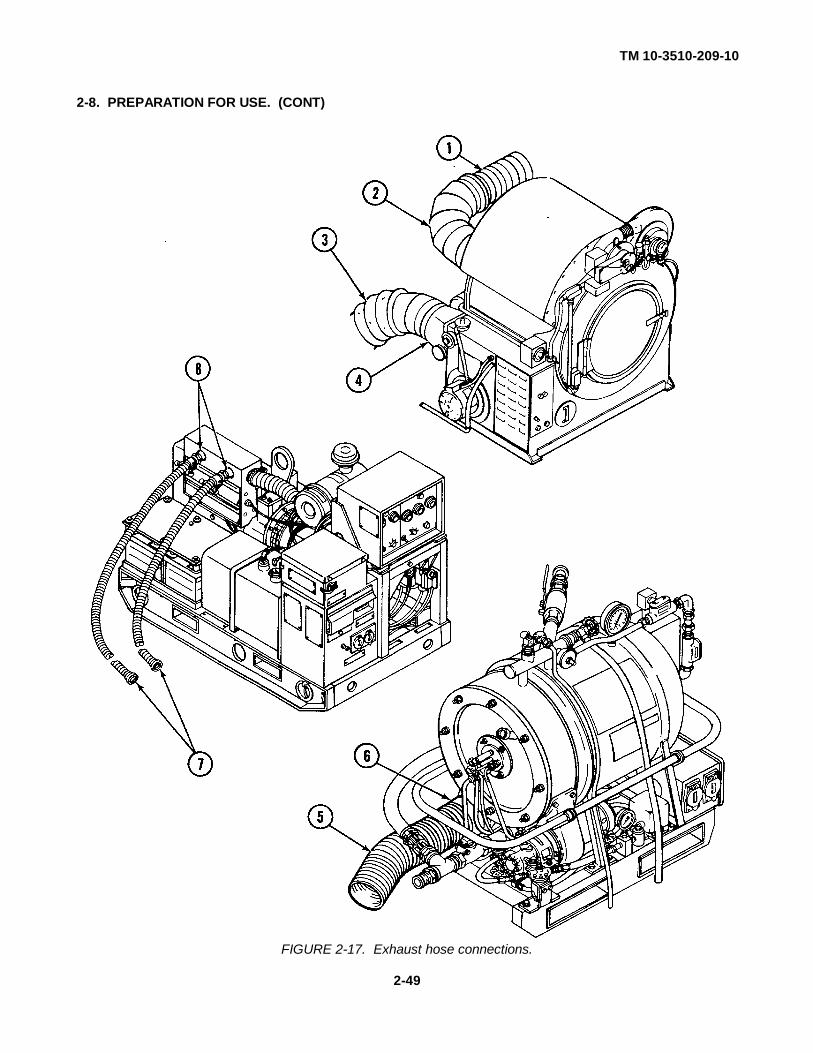
Ensure that exhaust ducts (1, 3, 5, and 7, FIG. 2-17) do not touch or cross otherexhaust ducts, power cables, fuel lines, or water hoses. Melting/damage can occurcausing leaking fuel and water or electrical hazards. Death by electrocution, fire,or explosion could result.
(2) Connect 5-inch (127 mm) combustion exhaust duct (1, FIG. 2-17) to dryer exhaust port (2).Extend duct away from trailer assembly. Do not touch or cross other exhaust ducts, powercables, water hoses, or fuel lines.
NOTE
The dryer lint duct is stored inside the dryer assembly during transportation.
(3) Obtain 12-inch (305 mm) lint duct (3) and install on dryer lint duct port(4) Extend duct full length along right side of trailer. Do not touch or cross other exhaust ducts,
power cables, water hoses, or fuel lines.
Change 1 2-47
TM 10-3510-209-10
2-7. SITE SELECTION, SETUP, AND ASSEMBLY. (CONT)
(4) Connect two 7-inch (178 mm) combustion exhaust ducts (5) together and connect to waterheater exhaust port (6). Extend duct full length away from rear of trailer. Do not touch orcross other exhaust ducts, power cables, water hoses, or fuel lines.
(5) Connect two 2-inch combustion exhaust ducts (7) to generator exhaust ports (8). Extendducts away from trailer assembly. Do not touch or cross other exhaust ducts, power cables,water hoses, or fuel lines.
2-8. PREPARATION FOR USE.
a. Generator. Ensure that the ON/OFF switch on the water pump and water heater are in the OFFposition and that all circuit breakers in the power distribution box are turned off.
FIGURE 2-16. Exhaust duct removal from trailer.
Change 1 2-48
TM 10-3510-209-10
2-8. PREPARATION FOR USE. (CONT)
FIGURE 2-17. Exhaust hose connections.
2-49

TM 10-3510-209-10
2-8. PREPARATION FOR USE. (CONT)
b. Generator.
WARNINGDo not operate the unit until the ground terminal stud of the engine-generator sethas been connected to a suitable ground. Electrical faults in the engine-generatorset, load lines, or load equipment can cause death by electrocution from contactwith an ungrounded system.
WARNING
Do not touch exhaust ducts while running or immediately after shutdown, as severeburns may result.
NOTE
The air compressor will operate when power is applied to the laundry facility andthe circuit breaker is on.
(1) Refer to TM 5-6115-585-12 for starting procedures for the generator and start the generator.
(2) Turn on all circuit breakers at power distribution panel.
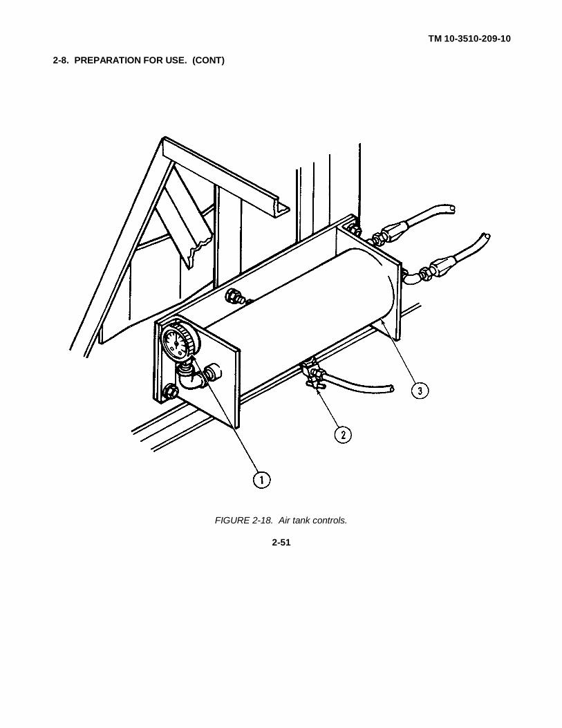
c. Air Compressor.
(1) Wait 2 minutes for pressure to build up inside air tank assembly and check air tank gage (1,FIG. 2-18) for an indication of 60 to 80 psi (414 to 552 kPa).
(2) Open drain valve (2) to bleed condensation from air tank (3).
(3) Close drain valve.
(4) Turn off generator. (Refer to TM 5-6115-585-12.)
(5) Listen for air leaks. If air leaks are found, report the problem to your supervisor. If leaks arenot found, restart generator.
Change 1 2-50
TM 10-3510-209-10
2-8. PREPARATION FOR USE. (CONT)
FIGURE 2-18. Air tank controls.
2-51
TM 10-3510-209-10
2-8. PREPARATION FOR USE. (CONT)
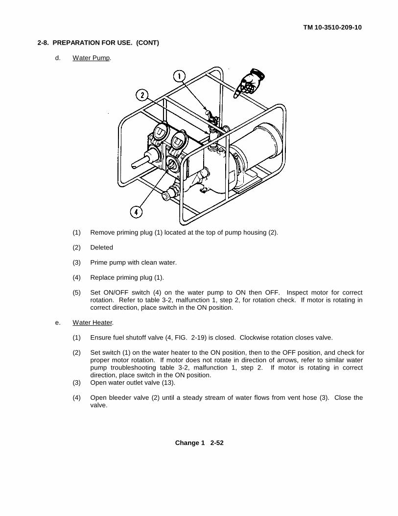
d. Water Pump.
(1) Remove priming plug (1) located at the top of pump housing (2).
(2) Deleted
(3) Prime pump with clean water.
(4) Replace priming plug (1).
(5) Set ON/OFF switch (4) on the water pump to ON then OFF. Inspect motor for correctrotation. Refer to table 3-2, malfunction 1, step 2, for rotation check. If motor is rotating incorrect direction, place switch in the ON position.
e. Water Heater.
(1) Ensure fuel shutoff valve (4, FIG. 2-19) is closed. Clockwise rotation closes valve.
(2) Set switch (1) on the water heater to the ON position, then to the OFF position, and check forproper motor rotation. If motor does not rotate in direction of arrows, refer to similar waterpump troubleshooting table 3-2, malfunction 1, step 2. If motor is rotating in correctdirection, place switch in the ON position.
(3) Open water outlet valve (13).
(4) Open bleeder valve (2) until a steady stream of water flows from vent hose (3). Close thevalve.
Change 1 2-52

TM 10-3510-209-10
2-8. PREPARATION FOR USE. (CONT)
FIGURE 2-19. Water heater controls.
Change 1 2-53
TM 10-3510-209-10
2-8. PREPARATION FOR USE. (CONT)
WARNING
Use only specified fuel (item 10, app C). Failure to do so may result in death orserious injury to personnel or damage to equipment.
(5) Remove priming plug (5) and prime fuel pump (6) by pouring fuel into the line. Installpriming plug.
(6) Open air shutter (7) halfway.(7) Open the door to control panel (8) and press FLAME SAFEGUARD reset button.(9) Close control panel.(8) Set water temperature control (11) to the desired setting. (Refer to FM 10-280, Field Laundry
Clothing Exchange and Bath Operations, for water temperatures.)(9) Place load limit switch (1) to the ON position.
WARNING
Do not touch exhaust ducts while running or immediately after shutdown, as severeburns may result.
NOTE
The water heater burner is equipped with an ultraviolet (UV) scanner and a flamesafeguard control unit to purge fumes or vapor from the combustion chamber priorto ignition. The control unit will also cause a safety shutdown if the burner doesnot ignite within a preset time.
(10) Check fuel pressure gage (10) for an indication of 75 to 80 psi (517 to 552 kPa). If thepressure gage does not indicate 75 to 80 psi (517 to 552 kPa) within 15 seconds, place loadlimit switch (1) to the OFF position and repeat steps (1) through (9) until a minimum of 75 to80 psi (517 to 552 kPa) is indicated on pressure gage (10). After three unsuccessfulattempts, notify your supervisor.
(11) As soon as 75 to 80 psi (517 to 552 kPa) is reached, open fuel shutoff valve (4) one full turn.The burner should ignite within 20 seconds and be visible in sight glass combustion chamber(12). Open valve fully.
Change 1 2-54
TM 10-3510-209-10
2-8. PREPARATION FOR USE. (CONT)
(12) If the water heater buzzer sounds on the control box, turn off load limit switch (1) and waitapproximately two minutes. Repeat steps (1) through (10) to start water heater.
(13) Adjust air shutter (7) until there is little or no smoke in the heater exhaust.
(14) When the water reaches the specified temperature (refer to FM 10-280), check temperaturegage reading with thermostat setting. The heater flame will shut off automatically and fuelpressure gage (10) will register zero.
Change 1 2-54.1/(2-54.2 blank)

TM 10-3510-209-10
2-8. PREPARATION FOR USE. (CONT)
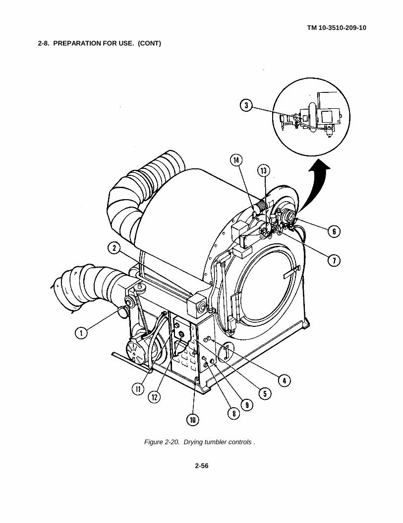
f. Drying Tumbler.
(1) Set thermoswitch (1, FIG. 2-20) as follows:
(a) For cotton: 250°F (121°C)
(b) For wool: 2000F (93°C)
(c) For battle dress uniform (BDU's): do not exceed 130°F (54°C).
(2) Set drying time control (2) to approximately 10 minutes.
(3) Adjust burner air intake (3) to approximately 1/2 inch (12.7 mm).
(4) Close fuel shutoff valve (7).(5) Loosen three screws (10) on panel door of dryer control panel (5) and open panel door.
(6) Press reset button (11) on safeguard control unit (12). Close and secure panel door with three screws (10).
(7) Push start/stop button (4) on dryer control panel (5).
(8) Check fuel pressure gage (6) for an indication of approximately 100 psi (690 kPa).(9) Open fuel shutoff valve (7) one full turn.
NOTE
The dryer burner is equipped with an ultraviolet (UV) scanner and a flamesafeguard control unit to purge fumes or vapor from the combustion chamber priorto ignition. The control unit will also cause a safety shutdown if the burner does notignite within a preset time.
(10) If dryer warning light (8) lights and beeper (9) sounds on the front of dryer control panel (5) perform the following:
(a) Push start/stop button (4) on dryer control panel (5).
(b) Loosen three screws (10) on panel door of dryer control panel (5) and open panel door.
(c) Wait for approximately 2 minutes after shutdown to allow for the safeguard timer to reset and cool the electrical igniter.
(d) Press and release reset button (11) on safeguard control unit (12). Position dryer control panel (5) and secure with three screws (10).
(e) Push start button (4) on dryer control panel (5).
2-55
TM 10-3510-209-10
2-8. PREPARATION FOR USE. (CONT)
Figure 2-20. Drying tumbler controls .
2-56
TM 10-3510-209-10
2-8. PREPARATION FOR USE. (CONT)
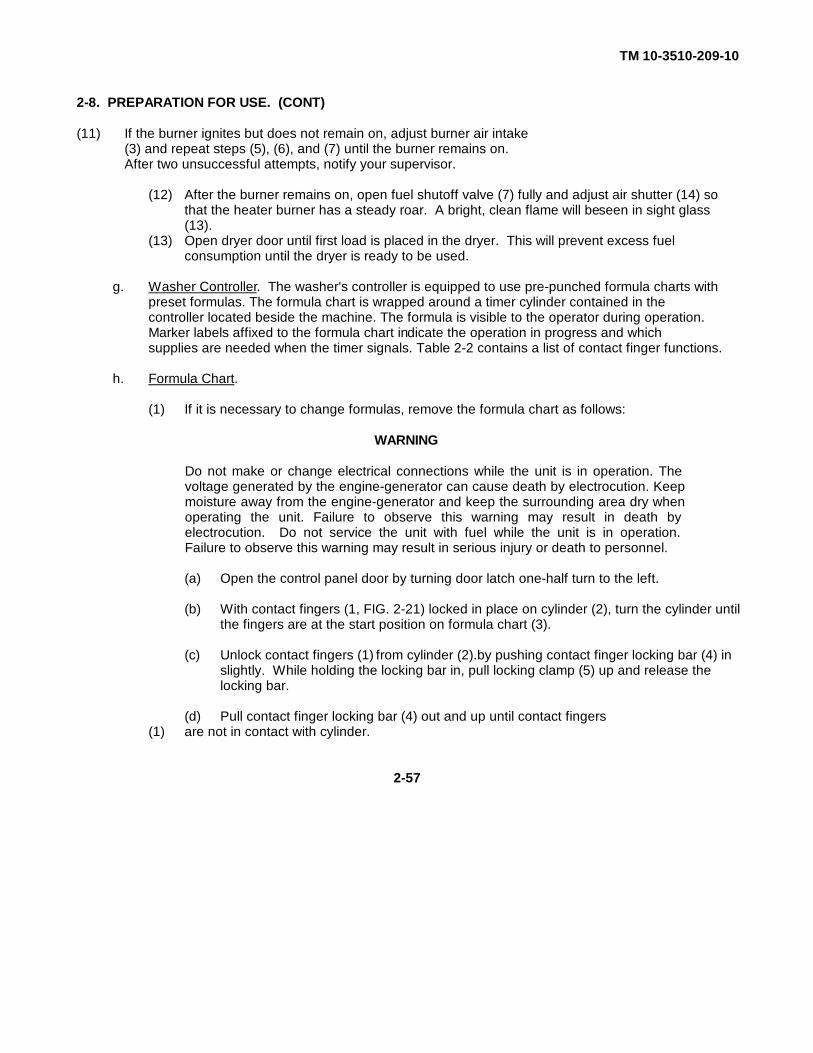
(11) If the burner ignites but does not remain on, adjust burner air intake(3) and repeat steps (5), (6), and (7) until the burner remains on.After two unsuccessful attempts, notify your supervisor.
(12) After the burner remains on, open fuel shutoff valve (7) fully and adjust air shutter (14) so that the heater burner has a steady roar. A bright, clean flame will be seen in sight glass (13).
(13) Open dryer door until first load is placed in the dryer. This will prevent excess fuel consumption until the dryer is ready to be used.
g. Washer Controller. The washer's controller is equipped to use pre-punched formula charts with preset formulas. The formula chart is wrapped around a timer cylinder contained in the controller located beside the machine. The formula is visible to the operator during operation. Marker labels affixed to the formula chart indicate the operation in progress and which supplies are needed when the timer signals. Table 2-2 contains a list of contact finger functions.
h. Formula Chart.
(1) If it is necessary to change formulas, remove the formula chart as follows:
WARNING
Do not make or change electrical connections while the unit is in operation. Thevoltage generated by the engine-generator can cause death by electrocution. Keepmoisture away from the engine-generator and keep the surrounding area dry whenoperating the unit. Failure to observe this warning may result in death byelectrocution. Do not service the unit with fuel while the unit is in operation.Failure to observe this warning may result in serious injury or death to personnel.
(a) Open the control panel door by turning door latch one-half turn to the left.
(b) With contact fingers (1, FIG. 2-21) locked in place on cylinder (2), turn the cylinder untilthe fingers are at the start position on formula chart (3).
(c) Unlock contact fingers (1) from cylinder (2).by pushing contact finger locking bar (4) in slightly. While holding the locking bar in, pull locking clamp (5) up and release the locking bar.
(d) Pull contact finger locking bar (4) out and up until contact fingers(1) are not in contact with cylinder.
2-57

TM 10-3510-209-10Table 2-2. Control Finger Functions
CONTROLFINGERNUMBER FUNCTION DESCRIPTION
11 Common Makes contact with cylinder at all times.
12 ODD Signal 1 - add soap When finger comes in contact withcylinder, a signal informs operator toadd soap.
13 EVEN Signal 2 - add supplies When finger comes in contact withcylinder, a signal informs operator toadd supplies.
14 Drain When finger breaks contact with cylinder,the drain valve opens and all the waterin the cylinder drains from the washer.
15 Hot water When finger comes in contact withcylinder, hot water enters the cylinder.
16 Cold water When finger comes in contact withcylinder, cold water enters the cylinder.
17 High/Low water level When finger comes in contact withcylinder, high water level or low waterlevel selected, depending on the waterlevel position.
18 Extra water When finger comes in contact withcylinder, extra water enters the cylinder.
19 Blank
20 Blank
21 Blank
22 Blank
23 Blank
24 Blank
25 Blank
2-58

TM 10-3510-209-10Table 2-2. Control Finger Functions
CONTROLFINGERNUMBER FUNCTION DESCRIPTION
26 Blank
27 Blank
28 Blank
29 Blank
30 Blank
31 Blank
32 Blank
2-8. PREPARATION FOR USE. (CONT)
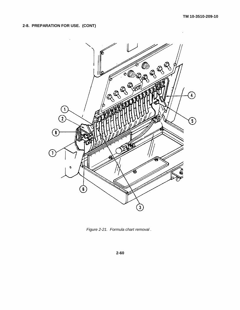
(e) Release the end of formula chart (3) attached with spring-loaded clamps (6) by pulling down on the right and left spring-loaded clamps and withdrawing formula chart bar (7).
(f) Release the opposite end of formula chart (3) by withdrawing formula chart bar (7) from right and left stationary clamps (8).
(g) Carefully remove formula chart (3) from cylinder (2) by pulling outward on the end of the chart that was secured by spring-loaded clamps (6).
(2) Install formula chart as follows:(a) With contact fingers (1, FIG. 2-22) locked in place on cylinder (2), turn the cylinder until
the fingers are at the start position on the cylinder.
(b) With formula chart (3) held so that the minute markers are in descending order, top to bottom, attach the bottom of the chart to right and left stationary clamps (8).
(c) Turn cylinder (2) until formula chart (3) wraps around the cylinder. The right edge of thechart must be even with the right edge of the cylinder.
(d) Unlock contact fingers (1) from cylinder (2) by pushing contact finger locking bar (4) in slightly. While holding the locking bar in, pull locking clamp (5) up and release the locking bar.
(e) Pull contact finger locking bar (4) up and out and up until contact fingers (1) are not in contact with cylinder (2).
2-59
TM 10-3510-209-10
2-8. PREPARATION FOR USE. (CONT)
Figure 2-21. Formula chart removal .
2-60
TM 10-3510-209-10
2-8. PREPARATION FOR USE. (CONT)
Figure 2-22 . Formula chart replacement .
2-61
TM 10-3510-209-10
2-8. PREPARATION FOR USE. (CONT)
(f) Attach the top of formula chart bar (7) to right and left spring-loaded clamps (6). Ensure clamps are properly connected together.
(g) Lock contact fingers (1) by pushing contact finger locking bar (4) down and in until locked in place by locking clamp (5).
(h) Close and secure the control panel door.
2-9. OPERATING PROCEDURES.
a. Automatic Washing. The following steps are for operating the washer using the automatic timer to control the wash cycle.
WARNING
MASTER switch on the control panel must be OFF while loading/unloading washor when not in use. The washing machine could be activated, causing seriousinjury to personnel.
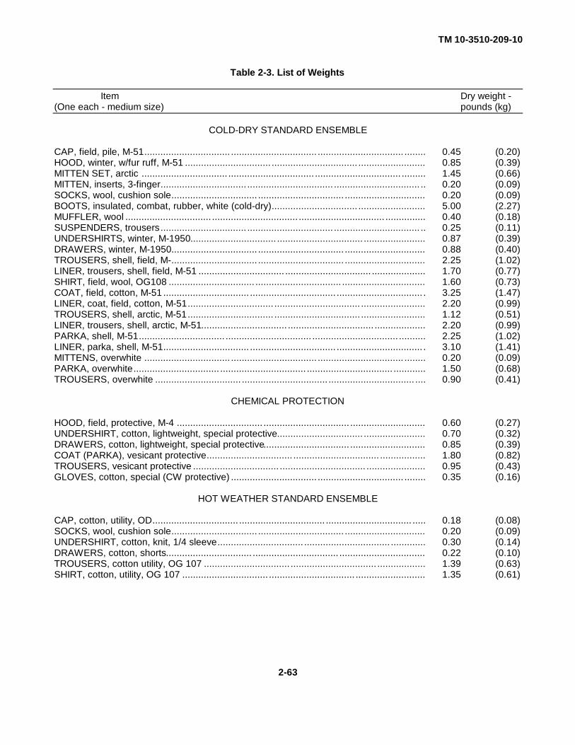
(1) Load the washer with up to 60 pounds (27.2 kg) of wash. Table 2-3 lists the weight of specificclothing items.
(2) Check the air tank pressure gage for a pressure of at least 60 psi (414 kPa).
NOTE
When washing camouflage clothing, use warm water and mild detergent. Do notuse chlorine bleach or starch on camouflage clothing.
(3) Add the proper amount of washing supplies through the soap chute. Refer to FM 10-280 for field laundry washing and decontamination formulas.
(4) Turn control knob (1, FIG. 2-23) until chart fingers are at the START marker on the formula chart.
(5) Place SIGNAL CANCEL switch (3) to START position and place remaining switches to FORMULA.
(6) Place master switch (4) to formula position.
(7) Turn cylinder until interior light (5) on the door comes on. This is the start of the automatic cycle.
(8) Select desired MOTOR switch (2) position. For normal work, set MOTOR switch to RUNS WHILE DRAINING position.
(9) When signal light (6) on the controller comes on and buzzer sounds, the operation markers affixed to the formula chart will show what supplies to add.
2-62
TM 10-3510-209-10
Table 2-3. List of Weights
Item Dry weight -(One each - medium size) pounds (kg)
COLD-DRY STANDARD ENSEMBLE
CAP, field, pile, M-51................................ ................................ ................................ ........ 0.45 (0.20)HOOD, winter, w/fur ruff, M-51 ................................ ................................ ......................... 0.85 (0.39)MITTEN SET, arctic ................................ ................................ ................................ ......... 1.45 (0.66)MITTEN, inserts, 3-finger................................ ................................ ................................ .. 0.20 (0.09)SOCKS, wool, cushion sole................................ ................................ .............................. 0.20 (0.09)BOOTS, insulated, combat, rubber, white (cold-dry)................................ ......................... 5.00 (2.27)MUFFLER, wool ................................ ................................ ................................ ............... 0.40 (0.18)SUSPENDERS, trousers................................ ................................ ................................ .. 0.25 (0.11)UNDERSHIRTS, winter, M-1950................................ ................................ ....................... 0.87 (0.39)DRAWERS, winter, M-1950................................ ................................ .............................. 0.88 (0.40)TROUSERS, shell, field, M-................................ ................................ .............................. 2.25 (1.02)LINER, trousers, shell, field, M-51 ................................ ................................ .................... 1.70 (0.77)SHIRT, field, wool, OG108 ................................ ................................ ............................... 1.60 (0.73)COAT, field, cotton, M-51 ................................ ................................ ................................ . 3.25 (1.47)LINER, coat, field, cotton, M-51................................ ................................ ........................ 2.20 (0.99)TROUSERS, shell, arctic, M-51................................ ................................ ........................ 1.12 (0.51)LINER, trousers, shell, arctic, M-51................................ ................................ ................... 2.20 (0.99)PARKA, shell, M-51................................ ................................ ................................ .......... 2.25 (1.02)LINER, parka, shell, M-51................................ ................................ ................................ . 3.10 (1.41)MITTENS, overwhite ................................ ................................ ................................ ........ 0.20 (0.09)PARKA, overwhite................................ ................................ ................................ ............ 1.50 (0.68)TROUSERS, overwhite ................................ ................................ ................................ .... 0.90 (0.41)
CHEMICAL PROTECTION
HOOD, field, protective, M-4 ................................ ................................ ............................ 0.60 (0.27)UNDERSHIRT, cotton, lightweight, special protective................................ ....................... 0.70 (0.32)DRAWERS, cotton, lightweight, special protective................................ ............................ 0.85 (0.39)COAT (PARKA), vesicant protective................................ ................................ ................. 1.80 (0.82)TROUSERS, vesicant protective ................................ ................................ ...................... 0.95 (0.43)GLOVES, cotton, special (CW protective) ................................ ................................ ........ 0.35 (0.16)
HOT WEATHER STANDARD ENSEMBLE
CAP, cotton, utility, OD................................ ................................ ................................ ..... 0.18 (0.08)SOCKS, wool, cushion sole................................ ................................ .............................. 0.20 (0.09)UNDERSHIRT, cotton, knit, 1/4 sleeve................................ ................................ ............. 0.30 (0.14)DRAWERS, cotton, shorts................................ ................................ ................................ 0.22 (0.10)TROUSERS, cotton utility, OG 107 ................................ ................................ .................. 1.39 (0.63)SHIRT, cotton, utility, OG 107 ................................ ................................ .......................... 1.35 (0.61)
2-63

TM 10-3510-209-10
Table 2-3. List of Weights (Continued)
Item Dry weight -(One each - medium size) pounds (kg)
HOSPITAL CLOTHING/LINEN
SLIPPERS, canvas, pair................................ ................................ ................................ 1.2860 (0.5833)CAP, operating, surgical, green................................ ................................ ..................... 0.0781 (0.0354)GOWN, operating, surgical, green................................ ................................ ................. 1.2600 (0.5715)TROUSERS, operating, surgical................................ ................................ .................... 0.7333 (0.3326)SHIRT, man's, operating................................ ................................ ................................ 0.7167 (0.3251)ROBE, dress, cord................................ ................................ ................................ ......... 2.2500 (1.0206)GOWN, operating, surgical, white................................ ................................ .................. 2.000 (0.9072)SHEET, bed, cotton, white................................ ................................ ............................. 2.000 (0.9072)PILLOWCASE, cotton, ................................ ................................ ................................ . 4.000 (1.8144)SHEET, bed, cotton, green................................ ................................ ............................ 2.000 (0.9072)SHEET, bed, cotton, fitted................................ ................................ ............................. 0.5833 (0.2646)BLANKET, bed, cotton, white................................ ................................ ......................... 3.3750 (1.5309)BLANKET, bed, wool, OD................................ ................................ .............................. 4.6667 (2.1168)
2-9. OPERATING PROCEDURES. (CONT)
NOTE
The washer will go through a complete cycle, signaling each time to add suppliesand at the end of the washing cycle. The timer will stop during filling until theselected water level is reached.
(10) When the timer signals, the timer will stop advancing. This ensures that no washing operation in the formula is passed. Add supplies according to formula chart and move the SIGNAL CANCEL switch (3) to the opposite position to continue washing.
(11) Set MASTER switch (4) to OFF position at the end of the cycle.
(12) Transfer laundry to the pre-extraction bin.
b. Manual Washing. The control assembly provides complete manual operation. With the MASTER switch in MANUAL position, the MOTOR switch, DRAIN switch, WATER LEVEL switch, and
WATER switches may be used to obtain whatever manual operation is desired. The following steps are for manual operation.
CAUTION
Any switch in the FORMULA position during manual washing may cause unwantedoperations during the wash and rinse cycles.
(1) Load the washer with up to 60 pounds (27.2 kg) of wash. Table 2-3 lists the weight of specificclothing items.
2-64
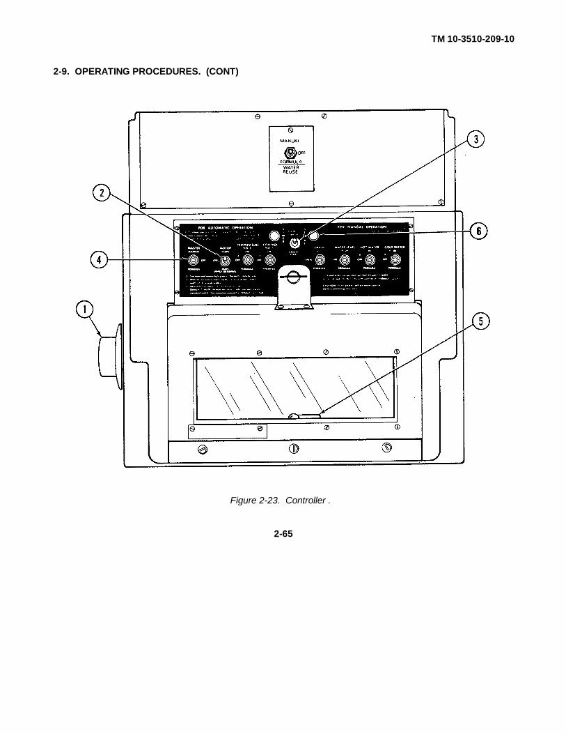
TM 10-3510-209-10
2-9. OPERATING PROCEDURES. (CONT)
Figure 2-23. Controller .
2-65
TM 10-3510-209-10
2-9. OPERATING PROCEDURES. (CONT)
(2) Select the proper formula from FM 10-280.
(3) Turn the cylinder to a blank position on the formula chart. In manual operation, first control finger (position 11) must make contact with the cylinder; all remaining contact fingers must not contact the cylinder.
(4) Check the air tank pressure gage for a pressure of at least 60 psi (414 kPa).
NOTE
Washer will not fill with water if the drain switch is in the open position.
(5) Select DRAIN, WATER LEVEL, and WATER TEMPERATURE switch positions and MOTOR switch operation as desired.
(6) Set MASTER switch to MANUAL position and set timer to desired setting. The washer will fill with water to the selected level of the selected temperature.
(7) Set TIMER ENABLED switch in the down position.
(8) Add the washing supplies through the soap chute.
NOTEWashing will continue indefinitely until the DRAIN switch is placed in the OPENposition. The DRAIN switch starts and stops each operation during manual wash.
(9) When SIGNAL LIGHT lights and buzzer sounds, set TIMER ENABLED switch to cancel position and set DRAIN switch to open position. Wait approximately 1 minute.
(10) When the machine has drained, the DRAIN switch may be moved to the SHUT position to commence another operation.
(11) Upon completion of MANUAL operation, set MASTER switch to OFF position.
(12) Transfer laundry to the pre-extraction bin.
2-66

TM 10-3510-209-10
2-9. OPERATING PROCEDURES. (CONT)
c. Extracting. (FIG. 2-3)
WARNING
While extractor basket is spinning, keep hands away. Failure to observe thiswarning may cause serious injury to personnel.
CAUTION
Do not force extractor lid open. Failure to observe this caution may cause seriousdamage to equipment.
(1) Place 30 pounds (13.6 kg) of laundry (approx one-half of a full load) from the pre-extraction bin into the extractor.
(2) Distribute load evenly around the basket for balance. Ensure articles are completely inside basket.
(3) Close the extractor lid.
(4) Pull out EMERGENCY STOP button.
(5) Set timer to desired setting (normally 3 minutes) and press START button. The lid will lock, the lid lock signal light will come on, and the machine will spin for the set time.
(6) Emergency stop procedures are as follows:
(a) If the machine vibrates excessively or is extremely noisy, or if something is caught between the basket and the curb, push the EMERGENCY STOP button.
(b) When the signal light goes out, open the lid and rebalance the load. Ensure nothing has dropped between the basket and the curb.
(c) To restart the extractor, pull out the EMERGENCY STOP button, close the lid, and press the START button. When extraction is completed, the basket will stop and the lidlock signal light will go out.
Change 1 2-67

TM 10-3510-209-10
2-9. OPERATING PROCEDURES. (CONT)
WARNING
While extractor basket is spinning, keep hands away. Failure to observe thiswarning may cause serious injury to personnel.
(7) When the lid light goes off, indicating the end of the cycle, pressEMERGENCY STOP button.
(8) Open the lid and transfer the load to the dryer.
(9) Repeat steps (1) thru (8) for the remainder of the wash load.
d. Drying.
WARNING
While dryer cylinder is spinning, keep hands away. Failure to observe this warningmay cause serious injury to personnel.
(1) Remove the load from the extractor and place no more than 30 pounds (13.6 kg) in the dryer.(2) Close the tumbler door securely.
(3) Set the temperature control as follows:
(a) For cotton: 250° (121°C).
(b) For wool: 200°F (93°C).(c) For battle dress uniforms (BDU's): 130°F (54°C).
(4) Set the drying time to approximately 10 minutes.
(5) Press start button on dryer.
(6) When the beeper sounds, turn timer off, open dryer door, and check laundry for dryness.
(7) If laundry is dry, remove. If laundry is not dry, repeat steps (4) and(5) using a 3-minute drying cycle until laundry is dry.
(8) Remove laundry from dryer and place in dryer bin.
2-68

TM 10-3510-209-10
2-9. OPERATING PROCEDURES. (CONT)
e. Shutdown Procedures.
NOTE
The laundry unit may begin to be shut down while the last load of wash is beingdried.
(1) Make certain that all washer control panel switches are in the OFF position.
(2) Turn off air compressor circuit breaker (3, FIG. 2-7) at the power distribution panel.
(3) Turn water temperature control (6, FIG. 2-4) to O0F (-180C). Allow the water heater to operate for 2 minutes so that the blower may purge vaporized fuel from the burner. Turn ON/OFF switch (7) to the OFF position and close fuel shutoff valve (9).
(4) Turn off start switch (1, FIG. 2-6) on the water pump.
(5) Turn dryer temperature control (9, FIG. 2-2) to O0F (-180C). Allow the dryer to operate for 2 minutes so that the blower may purge vaporized fuel from the burner. Press the stop button (5) and close fuel shutoff valve (12).
(6) Open the dryer door and allow the dryer to cool for 3 to 5 minutes.
(7) Set all circuit breakers on the power distribution box to off (FIG. 2-7).
(8) Refer to TM 5-6115-585-12 and shut down the generator set.
2-10. PREPARATION FOR MOVEMENT.
a. Perform shutdown operations. (Refer to para 2-9e.)
b. Remove tarp, two struts, and workstand support brackets from the hose basket and set aside.
WARNING
Use extreme care to avoid spilling fuel. Fuel is highly flammable and may explodeif exposed to heat or spark. Clean up spills as soon as possible. Failure to observethis warning may result in death or serious injury to personnel.
c. Disconnect and drain back into fuel source four fuel lines going to the dryer and water heater. Store fuel lines in hose basket.
d. Remove the drum fill adapters from the fuel source and store in hose baskets.
Change 1 2-69

TM 10-3510-209-10
2-10. PREPARATION FOR MOVEMENT. (CONT)
e. Disconnect water pump power cable and store in hose baskets.
CAUTION
Water in pipes and equipment can freeze during cold weather causing severedamage to equipment. Ensure that water is drained from pumps, lines, andequipment.
f. Disconnect and drain discharge hose (1) from water pump (2) and store hose in hose baskets.
Change 1 2-70
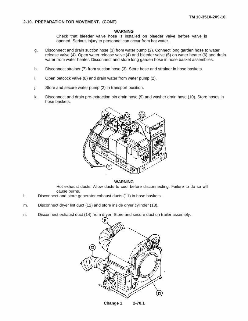
TM 10-3510-209-102-10. PREPARATION FOR MOVEMENT. (CONT)
WARNINGCheck that bleeder valve hose is installed on bleeder valve before valve isopened. Serious injury to personnel can occur from hot water.
g. Disconnect and drain suction hose (3) from water pump (2). Connect long garden hose to water release valve (4). Open water release valve (4) and bleeder valve (5) on water heater (6) and drainwater from water heater. Disconnect and store long garden hose in hose basket assemblies.
h. Disconnect strainer (7) from suction hose (3). Store hose and strainer in hose baskets.
i. Open petcock valve (8) and drain water from water pump (2).
j. Store and secure water pump (2) in transport position.
k. Disconnect and drain pre-extraction bin drain hose (9) and washer drain hose (10). Store hoses in hose baskets.
WARNINGHot exhaust ducts. Allow ducts to cool before disconnecting. Failure to do so willcause burns.
l. Disconnect and store generator exhaust ducts (11) in hose baskets.
m. Disconnect dryer lint duct (12) and store inside dryer cylinder (13).
n. Disconnect exhaust duct (14) from dryer. Store and secure duct on trailer assembly.
Change 1 2-70.1
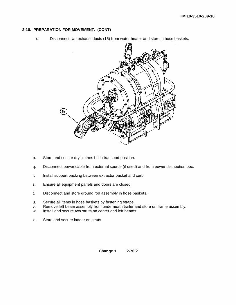
TM 10-3510-209-10
2-10. PREPARATION FOR MOVEMENT. (CONT)
o. Disconnect two exhaust ducts (15) from water heater and store in hose baskets.
p. Store and secure dry clothes bin in transport position.
q. Disconnect power cable from external source (if used) and from power distribution box.
r. Install support packing between extractor basket and curb.
s. Ensure all equipment panels and doors are closed.
t. Disconnect and store ground rod assembly in hose baskets.
u. Secure all items in hose baskets by fastening straps.v. Remove left beam assembly from underneath trailer and store on frame assembly.w. Install and secure two struts on center and left beams.
x. Store and secure ladder on struts.
Change 1 2-70.2
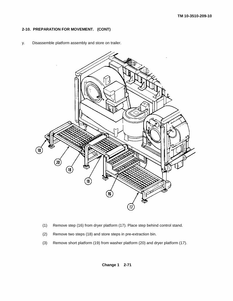
TM 10-3510-209-10
2-10. PREPARATION FOR MOVEMENT. (CONT)
y. Disassemble platform assembly and store on trailer.
(1) Remove step (16) from dryer platform (17). Place step behind control stand.
(2) Remove two steps (18) and store steps in pre-extraction bin.
(3) Remove short platform (19) from washer platform (20) and dryer platform (17).
Change 1 2-71

TM 10-3510-209-10
2-10. PREPARATION FOR MOVEMENT. (CONT)
(4) Remove ball locking pins (21) from washer platform. Adjust stabilizer bars (22) and insert ball locking pins in holes provided.
(5) Repeat step (4) for dryer platform assembly.
Change 1 2-72

TM 10-3510-209-10
2-10. PREPARATION FOR MOVEMENT. (CONT)
(6) Place dryer platform assembly (23) on trailer assembly and slide platform toward rear oftrailer.
(7) Install workstand storage support brace (24) on trailer assembly.
(8) Install ball locking pin (25) through dryer platform assembly (23) and workstand storagesupport brace (24).
(9) Install short platform assembly (26) on trailer assembly and secure short platform assemblyto dryer platform assembly (23) with clamp (27).
(10) Repeat procedures in steps (6), (7), and (8) for washer platform assembly (28).
(11) Secure dryer and washer platform assemblies (23) and (28) to trailer assembly with clamp(29).
z. Secure two transportation braces (30) to frame and trailer assembly.
aa. Cover laundry unit with tarp and secure tiedown ropes to trailer.
ab. Hitch laundry unit to towing vehicle, release handbrake, raise trailer supports, and remove wheelchocks. Refer to TM 9-2830-276-14&P.
Change 1 2-73

TM 10-3510-209-10
2-11. OPERATING INSTRUCTION ON DECALS AND INSTRUCTION PLATES .
FIGURE 2-24 shows the location and wording of the M85 laundry unit decals and operator caution and warningplates. Refer to the appropriate TM's for trailer and generator data plates.
FIGURE 2-24. Operating instructions on decals and plates.(sheet 1 of 4)
Change 1 2-74
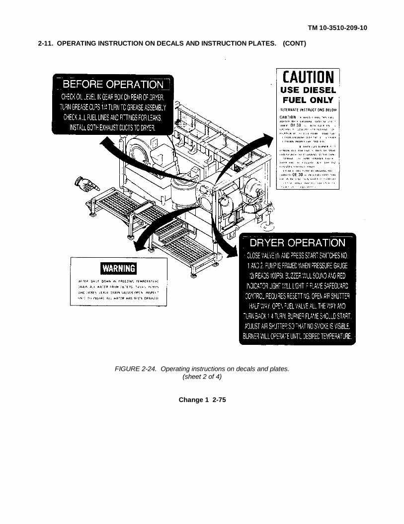
TM 10-3510-209-10
2-11. OPERATING INSTRUCTION ON DECALS AND INSTRUCTION PLATES. (CONT)
FIGURE 2-24. Operating instructions on decals and plates.(sheet 2 of 4)
Change 1 2-75
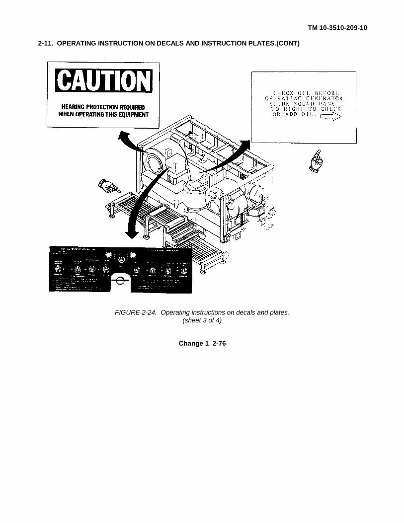
TM 10-3510-209-10
2-11. OPERATING INSTRUCTION ON DECALS AND INSTRUCTION PLATES.(CONT)
FIGURE 2-24. Operating instructions on decals and plates.(sheet 3 of 4)
Change 1 2-76
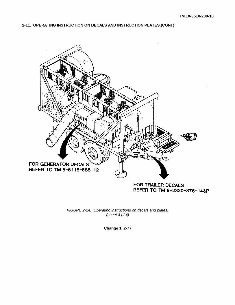
TM 10-3510-209-10
2-11. OPERATING INSTRUCTION ON DECALS AND INSTRUCTION PLATES.(CONT)
FIGURE 2-24. Operating instructions on decals and plates.(sheet 4 of 4)
Change 1 2-77

TM 10-3510-209-10
Section IV. OPERATION UNDER UNUSUAL CONDITIONS
Para Title Page
2-12 Operation in Extreme Cold................................ ................................ ...................... 2-782-13 Operation in Dust or Sand................................ ................................ ....................... 2-792-14 Operation in Snow and Mud................................ ................................ .................... 2-792-15 Operation in Saltwater Areas ................................ ................................ ................. 2-792-16 Emergency Procedures................................ ................................ ........................... 2-79
2-12. OPERATION IN EXTREME COLD (BELOW 0°F or -18°C)
WARNINGDo not touch cold metal parts with bare hands. Cold metal parts can causefrostbite and injury to personnel.
CAUTIONSubzero temperatures cause rubber and metal parts to become brittle and prone tobreakage. Use proper lubrication for extreme cold operations.
a. Lubrication of Generator Set. Refer to TM 5-6115-585-12 for proper lubrication in extreme cold(below 0°F or -18°C).
b. Lubrication of Laundry Unit. Ensure the laundry unit has been lubricated in accordance with LO 10-3510-209-12 for the air temperature expected.
c. Operation in Extreme Cold. During operation in extreme cold, steps must be taken to protect theequipment from freezing. Operate the unit inside a tent or other suitable enclosure if necessary.Water must be supplied without exposing the water pump or water hose to below-freezingtemperatures. After operation in extreme cold, perform the following:
(1) Shut down and drain water heater and water pump (refer to para 2-9e).
(2) Disconnect and drain hoses (refer to para 2-10).
(3) With the washer and compressor operating, switch the hot water and cold water switches onthe controller to manual position, with drain switch open and master switch at manual. Allow2 minutes to drain all water from the washer.
(4) Open the drain valve under the compressor air supply tank and drain condensation.
(5) Load the trailer and store it in a heated shelter if possible.
2-78

TM 10-3510-209-10
2-13. OPERATION IN DUST OR SAND.
a. Lubricate the equipment in accordance with the LO 10-3510-209-12.
WARNINGCompressed air used for cleaning purposes will not exceed 30 psi (207 kPa). Useonly with effective chip-guarding and personal-protective equipment (goggles,shield, gloves, etc.).
b. If possible, shut down the unit during severe dust storms and cover it with a tarpaulin or othersuitable protective covering. When the area is reasonably clear of dust, clean the unit thoroughly.Use dry compressed air to clean hard-to-reach places.
2-14. OPERATION IN SNOW AND MUD.
Take necessary precautions to ensure a firm footing for the platform by using a field-expedient blockingunderneath the platform pads.
2-15. OPERATION IN SALTWATER AREAS.
a. Inspect the laundry unit frequently for rust and corrosion. Rusted or corroded condition must becorrected immediately. If rust or corrosion is present, notify your supervisor.
CAUTIONDo not direct high-pressure water hose nozzles or steam cleaner nozzles intoelectrical connections/junction boxes.
b. Frequently wash the laundry unit to prevent a buildup of salt deposits.
2-16 EMERGENCY PROCEDURES.
CAUTIONLack of lubrication may cause pump damage when straight gasoline is used asfuel. To avoid failure, 1 quart (0.9 liter) of oil must be mixed with each 5 gallons(19 liters) of gasoline used.
a. The laundry unit is designed to operate on diesel fuel. Under emergency conditions the dryer andwater heater may be fueled with gasoline (item 11, app C). When using gasoline as the fuelsource, 1 quart of OE-30 weight oil (item 13, app C) must be added to 5 gallons of gasoline.
b. There is no alternative fuel source for the generator.
2-79/(2-80 blank)
TM 10-3510-209-10
CHAPTER 3
MAINTENANCE INSTRUCTIONS
Section I. LUBRICATING INSTRUCTIONS
Para Title Page
3-1 Laundry Unit Lubrication................................ ................................ ......................... 3-13-2 Generator Lubrication................................ ................................ ............................. 3-13-3 Trailer Lubrication................................ ................................ ................................ ... 3-1
3-1. LAUNDRY UNIT LUBRICATION.
Refer to LO 10-3510-209-12 for operator lubrication of the M85 Laundry Unit.
3-2. GENERATOR LUBRICATION.
Refer to LO 5-6115-585-12 for lubrication instructions on the 10-kW generator.
3-3. TRAILER LUBRICATION.
Refer to TM 9-2330-376-14&P for lubrication instructions on the trailer.
Section II. TROUBLESHOOTING PROCEDURES
Para Title Page
3-4 Introduction ................................ ................................ ................................ ............ 3-13-5 Troubleshooting................................ ................................ ................................ ...... 3-1
3-4. INTRODUCTION.
a. Table 3-1 lists the common malfunctions which you may find during operation or maintenance ofthe laundry unit or its components. You should perform tests/inspections and corrective actions inthe order listed.
b. This manual cannot list all malfunctions that may occur nor all tests or inspections and correctiveactions. If a malfunction is not listed or is not corrected by listed corrective actions, notify yoursupervisor.
3-5. TROUBLESHOOTING.
Use the symptom index in table 3-1 for quick access to troubleshooting procedures in table 3-2.
3-1

TM 10-3510-209-10
Table 3-1. Symptom Index
TroubleshootingProcedure
Symptom Page
1. Water pump fails to deliver water................................ ................................ .................. 3-22. Water heater and dryer fail to start................................ ................................ ................ 3-33. Flame fails in burner (water heater/dryer)................................ ................................ ...... 3-55. Fuel pressure too low or fuel pressure pulsates (water
heater/dryer)................................ ................................ ................................ ........ 3-66. Fuel pump fails to deliver fuel to burner (water heater/dryer)................................ ......... 3-77. Black smoke comes out of burner exhaust duct (water heater/dryer)............................. 3-88. Extractor fails to start ................................ ................................ ................................ .... 3-89. Extractor basket fails to turn................................ ................................ .......................... 3-910. Extractor fails to drain ................................ ................................ ................................ .. 3-911. Washer fails to fill with water................................ ................................ ......................... 3-912. Washer fills with wrong amount of water................................ ................................ ....... 3-1013. Washer fills with wrong temperature of water ................................ ............................... 3-1014. Washer fails to tumble ................................ ................................ ............................... .. 3-1115. Washer fails to drain ................................ ................................ ................................ .... 3-12
Table 3-2. Troubleshooting
MALFUNCTIONTEST OR INSPECTION
CORRECTIVE ACTION
1. WATER PUMP FAILS TO DELIVER WATER.
Step 1. Check that electrical power is available and properly connected to water pump.
a. If no power is available, report problem to unit maintenance.
b. If power is available, proceed to next step.
Step 2. Check water pump motor for reversed rotation.
a. Set ON/OFF Switch to ON. Inspect motor for correct rotation. Motor should rotate indirection of arrow.
b. If rotation is incorrect, check all other motors on laundry unit for proper rotation. If allmotors are rotating backwards, shut down power and reverse any two phase leads (L1,L2, L3) at the generator connection.
c. If some (but not all) motors are rotating backwards, notify your supervisor.
d. If motor is rotating in proper direction, proceed to next step.
3-2
TM 10-3510-209-10
Table 3-2. Troubleshooting (Continued)MALFUNCTION
TEST OR INSPECTIONCORRECTIVE ACTION
1. WATER PUMP FAILS TO DELIVER WATER. (Cont)
Step 3. Check pump to verify that it has been adequately primed.
a. If pump is not primed, refer to paragraph 2-8c and prime the pump.
b. If pump has been adequately primed, proceed to step 4.
Step 4. Check water source to see if it is too shallow.
a. If water source is too shallow, remove suction hose and place it in deeper water. Referto FM 10-280.
b. If water source is not too shallow, proceed to step 5.
Step 5. Check suction hose and strainer for clogs.
a. If suction hose is clogged, remove and clean suction strainer.
b. If suction hose is not clogged, proceed to step 6.
Step 6. Check hose assemblies for air leaks.
a. If air leaks are present, repair or replace hose assemblies. Repair hose assembly bytightening hose clamps.
b. If air leaks are not present and problem persists, notify your supervisor.
2. WATER HEATER AND DRYER FAIL TO START.
Step 1. Check to see if flame safeguard control lockout switch is tripped.
a. If switch is tripped, refer to paragraph 2-8e(8) for the dryer and paragraph 2-8d(6) for thewater heater and reset flame safeguard control lockout switch.
b. If switch is not tripped, proceed to next step.
Step 1.1. Check to see if three circuit breakers inside of control panel are tripped.
a. If circuit breakers are tripped, reset circuit breakers by pushing them in.
b. If circuit breakers are not tripped and dryer still fails to start, proceed to next step.
Step 2. Check that water temperature thermostat on the water heater is set high enough to startthe water heater.
a. If thermostat setting is not high enough, increase thermostat setting.
b. If water heater still does not start, proceed to next step.
Change 1 3-3

TM 10-3510-209-10
Table 3-2. Troubleshooting (Continued)MALFUNCTION
TEST OR INSPECTIONCORRECTIVE ACTION
2. WATER HEATER AND DRYER FAIL TO START. (Cont)
Step 3. Check water supply in water heater tank.
a. If water supply is low, fill water heater tank with water.
b. If water heater tank is full, proceed to next step.
Step 4. Check to see if load limit switch is tripped.
a. If switch is tripped, move switch to OFF for 10 seconds, then to ON.
b. If switch is not tripped, proceed to next step.
Step 5. Check that electrical power is available to dryer and water heater. Check circuit breakerson power distribution panel.
a. If no power is available, report problem to your supervisor.
b. If power is available, proceed to next step.
Step 6. Check to see if blower motor reset button is tripped.
a. If button is tripped, reset blower motor reset button.
b. If reset button is not tripped, notify your supervisor.
3. FLAME FAILS IN BURNER (WATER HEATER/DRYER).
WARNING
Fuel is very flammable and can explode easily. To avoid serious injury or death,keep fuel away from open fire and keep fire extinguisher within easy reach whenworking with fuel. Do not work on fuel system when burner is hot. Fuel can beignited by hot burner. Shut off engine and do not smoke while refueling.
Step 1. Check fuel supply in fuel drum.
a. If fuel supply is low, fill fuel drum.
b. If fuel supply is adequate, proceed to next step.
3-4

TM 10-3510-209-10
Table 3-2. Troubleshooting (Continued)MALFUNCTION
TEST OR INSPECTIONCORRECTIVE ACTION
3. FLAME FAILS IN BURNER (WATER HEATER/DRYER). (Cont)
Step 2. Inspect fuel hose for air leaks.
a. If leaks are present, tighten fuel hose connections.
b. If no leaks are present, proceed to next step.
Step 3. Check feed and return fuel hose assemblies to see if they are reversed.
a. If feed and return fuel hoses are reversed, disconnect and reconnect fuel hoseassemblies in correct positions.
b. If feed and return fuel hoses are in correct positions, proceed to next step.
Step 4. Check fuel pump to verify that it has been primed.
a. If fuel pump has not been primed, refer to paragraph 2-8d and prime pump.
b. If fuel pump has been primed, proceed to next step.
Step 5. Check to see if flame safeguard switch is tripped.
a. If flame safeguard switch is tripped, refer to paragraph 2-8e for the dryer and paragraph2-8d for the water heater and reset flame safeguard switch.
b. If switch is not tripped, proceed to next step.
Step 6. Check ignition cable assemblies for loose connections at electrode and transformer ends.
a. If connections are loose, tighten connections at electrode and transformer ends.
b. If connections are not loose, notify your supervisor.
4. FUEL PRESSURE TOO HIGH (WATER HEATER/DRYER).
Check fuel pressure gage on the water heater for an indication of 80 psi (552 kPa) and the dryer for over 100 psi (690 kPa).
If gages indicate more than the specified amounts, notify your supervisor.
3-5
TM 10-3510-209-10
Table 3-2. Troubleshooting (Continued)MALFUNCTION
TEST OR INSPECTIONCORRECTIVE ACTION
5. FUEL PRESSURE TOO LOW OR FUEL PRESSURE PULSATES (WATER HEATER/DRYER).
WARNING
Fuel is very flammable and can explode easily. To avoid serious injury or death,keep fuel away from open fire and keep fire extinguisher within easy reach whenworking with fuel. Do not work on fuel system when burner is hot. Fuel can beignited by hot burner. Shut off engine and do not smoke while refueling.
Step 1. Check fuel supply in fuel drum.
a. If fuel supply is low, fill-fuel drum.
b. If fuel supply is adequate, proceed to next step.
Step 2. Inspect fuel hose for air leaks.
a. If leaks are present, tighten fuel hose connections.
b. If no leaks are present, proceed to next step.
Step 3. Check feed and return fuel hose assemblies to see if they are reversed.
a. If feed and return fuel hoses are reversed, disconnect and reconnect fuel hoseassemblies in correct positions.
b. If feed and return fuel hoses are in correct position, proceed to next step.
Step 4. Check fuel pump to verify that it has been primed.
a. If fuel pump has not been primed, refer to paragraph 2-8d and prime pump.
b. If fuel pump has been primed, proceed to next step.
Step 5. Inspect fuel filter cover for loose hardware.
a. If fuel filter cover is loose, tighten connections.
b. If fuel filter cover is not loose, report problem to your supervisor.
3-6

TM 10-3510-209-10
Table 3-2. Troubleshooting (Continued)MALFUNCTION
TEST OR INSPECTIONCORRECTIVE ACTION
5. FUEL PRESSURE TOO LOW OR FUEL PRESSURE PULSATES (WATER HEATER/DRYER). (Cont).
Step 6. Check for clogged fuel filter.
a. If fuel filter is clogged, refer to paragraph 3-7 and perform maintenance on fuel filter.
b. If problem persists, notify your supervisor.
6. FUEL PUMP FAILS TO DELIVER FUEL TO BURNER (WATER HEATER/DRYER).
WARNING
Fuel is very flammable and can explode easily. To avoid serious injury or death,keep fuel away from open fire and keep fire extinguisher within easy reach whenworking with fuel. Do not work on fuel system when burner is hot. Fuel can beignited by hot burner. Shut off engine and do not smoke while refueling.
Step 1. Check for proper rotation of fuel pump.
a. If fuel pump rotates in wrong direction, notify your supervisor.
b. If fuel pump rotates in proper direction, proceed to next step.
Step 2. Check fuel supply in fuel drum.
a. If fuel supply is low, fill fuel drum.
b. If fuel supply is adequate, proceed to next step.
Step 3. Inspect fuel hose for air leaks.
a. If leaks are present, tighten fuel hose connections.
b. If no leaks are present, proceed to next step.
Step 4. Check supply and return hose assemblies to see if they are reversed.
a. If supply and return hoses are reversed, disconnect and reconnect them in properpositions.
b. If supply and return hoses are not reversed, proceed to next step.
Step 5. Check fuel pump to verify that it has been primed.
a. If fuel pump has not been primed, refer to paragraph 2-8d and prime pump.
b. If fuel pump has been primed, proceed to next step.
3-7
TM 10-3510-209-10
Table 3-2. Troubleshooting (Continued)MALFUNCTION
TEST OR INSPECTIONCORRECTIVE ACTION
6. FUEL PUMP FAILS TO DELIVER FUEL TO BURNER (WATER HEATER/DRYER). (Cont)
Step 6. Inspect fuel filter cover for loose hardware.
a. If fuel filter cover is loose, secure hardware.
b. If fuel filter cover is not loose, proceed to next step.
Step 7. Check for clogged fuel filter.
a. If fuel filter is clogged, refer to paragraph 3-7 and perform maintenance on fuel filter.
b. If problem persists, notify your supervisor.
7. BLACK SMOKE COMES OUT OF BURNER EXHAUST DUCT (WATER HEATER/DRYER).
Check to see if fuel-to-air ratio adjustment is correct.
a. If fuel-to-air ratio adjustment is incorrect, refer to paragraph 3-7 and adjust shutter forproper volume of air intake.
b. If fuel-to-air ratio adjustment is correct, notify your supervisor.
8. EXTRACTOR FAILS TO START.
Step 1. Check emergency stop button and see if it is pushed in.
a. If emergency stop button is pushed in, reset by pulling emergency stop button out.
b. If emergency stop is reset, proceed to next step.
Step 2. Check lid on extractor and make sure it is closed and locked in position.
a. If lid is open, close and lock in correct position.
b. If lid is closed and locked in position, proceed to next step.
Step 3. Check to see if power is available to extractor. Check to see if circuit breaker on powerdistribution panel is off.
a. If circuit breaker is off, reset circuit breaker.
b. If power is not available, notify your supervisor.
3-8

TM 10-3510-209-10
Table 3-2. Troubleshooting (Continued)MALFUNCTION
TEST OR INSPECTIONCORRECTIVE ACTION
9. EXTRACTOR BASKET FAILS TO TURN.
Check lid on extractor and make sure it is closed. Inspect indicator light on control box. Indicator shouldlight if lid is closed.
a. If lid is not closed, close lid and press start button.
b. If lid is closed and extractor basket will not turn after pressing start button, report problemto unit maintenance.
10. EXTRACTOR FAILS TO DRAIN.
Remove and inspect drain hose for kinks and/or clogged condition.
a. If hose is clogged, remove hose and remove clog.
b. If drain is not kinked or clogged, notify your supervisor.
11. WASHER FAILS TO FILL WITH WATER.
Step 1. Check water pump for proper operation. Refer to malfunction 1.
a. If water pump is not operational, notify your supervisor.
b. If water pump is operational, proceed to next step.
Step 2. Inspect input line for kinks and/or loose connections.
a. Straighten lines and secure connections.
b. If washer still fails to fill, proceed to next step.
Step 3. Check to see if hot and cold water valves operate. Valves should open and close whenswitches on the controller are activated.
a. If valves do not operate properly, notify your supervisor.
b. If washer still fails to fill, proceed to next step.
Step 4. Check air pressure gage on air tank for an indication of at least 70 psi (483 kPa).
a. If pressure is 70 psi (483 kPa) or above, proceed to next step.
b. If pressure is below 70 psi (483 kPa) check circuit breaker on power distribution box forthe air compressor.
3-9
TM 10-3510-209-10
Table 3-2. Troubleshooting (Continued)MALFUNCTION
TEST OR INSPECTIONCORRECTIVE ACTION
11. WASHER FAILS TO FILL WITH WATER. (Cont)
Step 5. Check water float level.
Check float rod to see if it is sticking. If float rod is sticking and cannot be freed or is damaged,notify your supervisor.
12. WASHER FILLS WITH WRONG AMOUNT OF WATER.
Step 1. Inspect controller switches to determine whether switches are in the correct positions.
a. Set switches on controller to compensate.
b. If problem persists, proceed to next step 2.
Step 2. Check to see if float level (2, FIG. 2-1) is sticking.
a. Free the float operation.
b. If water level problems persist, report problem to unit maintenance.
Step 3. Check to see if hot and cold water valves operate. Valves should open and close whenswitches on controller are activated.
a. If valves do not operate properly, notify your supervisor.
b. If valves operate properly, proceed to next step.
Step 4. Check air pressure gage on air tank for an indication of at least .70 psi (483 kPa).
a. If pressure is below 70 psi (483 kPa), check circuit breaker on power distribution box forthe air compressor.
b. If pressure is 70 psi (483 kPa), notify your supervisor.
13. WASHER FILLS WITH WRONG TEMPERATURE OF WATER.
Step 1. Check for proper switch settings on controller.
a. Set switches to proper setting.
b. If temperature problem persists, proceed to next step.
3-10

TM 10-3510-209-10
Table 3-2. Troubleshooting (Continued)MALFUNCTION
TEST OR INSPECTIONCORRECTIVE ACTION
13. WASHER FILLS WITH WRONG TEMPERATURE OF WATER. (Cont)
Step 2. Check for proper thermostat setting on water heater.
a. If setting is incorrect, refer to malfunction 2, step 2.
b. If correct temperature cannot be obtained, notify your supervisor.
14. WASHER FAILS TO TUMBLE.
Step 1. Check positions of switches on controller.
a. Position the switches to effect proper tumbling action.
b. If washer still fails to tumble, proceed to next step.
Step 2. Check to ensure washer door is closed.
a. If the door is not closed, close the door and secure.
b. If door is closed and secure, proceed to next step.
Step 3. Check to see if controller reset button (22, FIG. 2-1) is tripped.
a. If controller reset button is tripped, push reset button.
b. If reset button is not tripped, proceed to next step.
WARNING
Remove rings, bracelets, wristwatches, and neck chains before working around oron the laundry unit. Jewelry can catch on equipment and cause injury, or mayshort across an electrical circuit and cause severe burns or electrical shock.Ensure circuit breakers are in the OFF position.
Step 4. Check drive mechanism for missing or damaged belt. Report missing or damaged beltsto your supervisor.
3-11
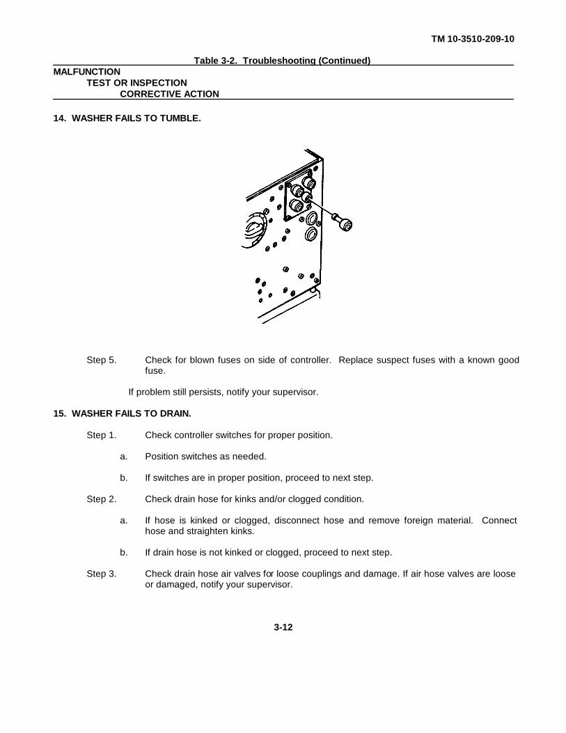
TM 10-3510-209-10
Table 3-2. Troubleshooting (Continued)MALFUNCTION
TEST OR INSPECTIONCORRECTIVE ACTION
14. WASHER FAILS TO TUMBLE.
Step 5. Check for blown fuses on side of controller. Replace suspect fuses with a known goodfuse.
If problem still persists, notify your supervisor.
15. WASHER FAILS TO DRAIN.
Step 1. Check controller switches for proper position.
a. Position switches as needed.
b. If switches are in proper position, proceed to next step.
Step 2. Check drain hose for kinks and/or clogged condition.
a. If hose is kinked or clogged, disconnect hose and remove foreign material. Connecthose and straighten kinks.
b. If drain hose is not kinked or clogged, proceed to next step.
Step 3. Check drain hose air valves for loose couplings and damage. If air hose valves are looseor damaged, notify your supervisor.
3-12
TM 10-3510-209-10
Section III. MAINTENANCE PROCEDURES
Para Title Page
3-6 Introduction ................................ ................................ ................................ .................... 3-133-7 Maintenance Procedures................................ ................................ ................................ 3-13
3-6. INTRODUCTION . This section provides instructions for inspection, service, and adjustment ofassemblies and subassemblies of the laundry unit. Each maintenance procedure contains step-by-stepinstructions for the task to be performed.
3-7. MAINTENANCE PROCEDURES .
a. Generator Maintenance. Refer to TM 5-6115-585-12 for performing maintenance on the 10-kWgenerator.
b. Trailer Assembly Maintenance. Refer to TM 9-2330-376-14&P for performing maintenance on thetrailer assembly.
c. Water Heater Fuel Filter Maintenance. These instructions tell how to inspect and service the fuelfilter assembly on the laundry water heater.
(1) Inspect fuel filter assembly for damage and leaks.
3-13
TM 10-3510-209-10
3-7. MAINTENANCE PROCEDURES. (CONT)
(2) Service fuel filter by turning handle (1) a few times to clean the permanent element. Removedrain plug (2) and allow moisture and sediment to drain from bowl. Install drain plug.
d. Water Heater Air Shutter Assembly Maintenance. These instructions tell how to inspect and adjust theair shutter assembly on the water heater.
(1) Inspect air shutter for binding of moving parts and for damage.
(2) Adjust air shutter (3) by grasping slider band (4) and rotating band up or down to increase ordecrease air opening. Adjust air opening during operation to obtain a light-colored exhaust andrumble-free operation.
3-14

TM 10-3510-209-10
3-7. MAINTENANCE PROCEDURES. (CONT)
e. Drying Tumbler Fuel Filter Maintenance. These instructions tell how to inspect and service the fuelfilter assembly on the laundry drying tumbler.
(1) Inspect fuel filter assembly for damage and leaks.
(2) Service fuel filter by removing drain plug (1) on bottom of bowl (2). Open air vent screw (3) on topof filter assembly. Drain enough fuel from bowl to remove contaminants. Tighten air vent screw and closedrain valve.
3-15

TM 10-3510-209-10
3-7. MAINTENANCE PROCEDURES. (CONT)
f. Drying Tumbler Air Shutter Assembly Maintenance. These instructions tell how to inspect and adjustthe air shutter assembly on the drying tumbler.
(1) Inspect burner air intake (1) for damage and for binding of moving parts.
(2) Adjust burner air intake (1) by loosening wingbolt (2) and sliding band. (3) up or down to increase or decrease air opening. Adjust air shutter. (4) during operation to obtain a light-colored exhaust and rumble-free operation.
3-16

TM 10-3510-209-10
APPENDIX A
REFERENCES
A-1. SCOPE. This appendix lists all forms, field manuals, technical manuals and other publicationsreferenced in this manual. Also listed are those publications that should be consulted for additional informationabout the laundry unit and its major components.
A-2. ADMINISTRATIVE PUBLICATIONS.
a. Pamphlets.
DA PAM 738-750 The Army Maintenance Management System (TAMMS)
b. Forms.
DA FORM 2028 Recommended Changes to Publications and Blank Forms
DA FORM 2028-2 Recommended Changes to Equipment TechnicalPublications
DA Form 2404 Equipment Inspection and Maintenance Worksheet
DA FORM 2407 Maintenance Request
DA FORM 2408 Equipment Log Assembly (Records)
SF 368 Quality Deficiency Report
A-3. TECHNICAL PUBLICATIONS.
a. Manuals
FM 9-207 Operation and Maintenance of Ordnance Materialin Cold Weather (O Deg to Minus 65 Deg F)
FM 10-280 Field Laundry Clothing Exchange and BathOperations
FM 21-11 First Aid for Soldiers
FM 31-70 Basic Cold Weather Manual
FM 31-71 Northern Operations
TM 10-3510-209-24P Unit, Intermediate Direct Support, andIntermediate General Support Maintenance RepairParts and Special Tools Lists, Laundry,Trailer-Mounted, Army Model M85
A-1

TM 10-3510-209-10
A-3. TECHNICAL PUBLICATIONS. (CONT)
TM 10-3510-209-24 Unit, Intermediate Direct Support, andIntermediate General Support Maintenance Manual;Laundry, Trailer-Mounted, Army Model M85
TM 5-6115-585-12 Operator and Organizational Maintenance Manualfor Generator Set, Diesel, Engine Driven, 10 kW,60 Hz
TM 9-2330-376-14&P Operator's, Organizational, Direct Support, andGeneral Support Maintenance Manual for Trailer,Flatbed, General Purpose, 5-Ton, 4-Wheel,M1061 El
TM 750-244-6 Procedures for Destruction of Tank-AutomotiveEquipment to Prevent Enemy Use
b. Lubrication Order
LO 10-3510-209-12 Lubrication Order, Laundry Unit,Trailer-Mounted, M85
LO 5-6115-585-12 Lubrication Order, Generator Set, Diesel EngineDriven, Tactical Skid Mounted, 10 kW
LO 9-2330-376-14&P Lubrication Order, Trailer, Flatbed, GeneralPurpose, 5-Ton, 4-Wheel, XM1061 El
A-2
TM 10-3510-209-10
APPENDIX B
COMPONENTS OF END ITEM AND BASIC ISSUE ITEMS LISTS
Section I. INTRODUCTION
B-1. SCOPE. This appendix lists components of end item and basic issue items for the laundry unit to helpyou inventory items required for safe and efficient operation.
B-2. GENERAL. The Components of End Item and Basic Issue Items lists are divided into the followingsections:
a. Section II. Components of End Item. This listing is for informational purposes only, and is notauthority to requisition replacements. These items are part of the end item, but are removed and separatelypackaged for transportation or shipment. As part of the end item, these items must be with the end itemwhenever it is issued or transferred between property accounts. Illustrations are furnished to assist you inidentifying the items.
b. Section III. Basic Issue Items. These are the minimum essential items required to place thelaundry unit in operation, to operate it, and to perform emergency repairs. Although shipped separatelypackaged, BII must be with the laundry unit during operation and whenever it is transferred between propertyaccounts. The illustrations will assist you with hard-to-identify items. This manual is your authority torequest/requisition replacement BII, based on TOE/MTOE authorization of the end item.
B-3. EXPLANATION OF COLUMNS . The following provides an explanation of columns found in the tabularlistings:
a. Column (1)-Illustration Number (Illus Number). This column indicates the number of the illustrationin which the item is shown.
b. Column (2)-National Stock Number. Indicates the National Stock Number assigned to the item andwill be used for requisitioning purposes.
c. Column (3)-Description. Indicates the Federal item name and, if required, a minimum descriptionto identify and locate the item. The last line for each item indicates the CAGE (in parentheses) followed by thepart number.
d. Column (4)-Unit of Measure. (U/M). Indicates the measure used in performing the actualoperational/maintenance function. This measure is expressed by a two-character alphabetical abbreviation(e.g., ea, in., pr).
e. Column (5)-Quantity Required (Qty Reqd). Indicates the quantity of the item authorized to be usedwith/on the equipment.
B-1
TM 10-3510-209-10
Section II. COMPONENTS OF END ITEM
(1) (2) (3) (4) (5)ILLUS NATIONAL STOCK DESCRIPTION QTYNO. NUMBER CAGE AND PART NUMBER U/M REQD
1 BASKET ASSY, HOSE EA 2(81337) 6-1-9955
2 BEAM ASSY, LEFT EA 1(81337) 6-2-2418
3 3510-01-248-5296 BIN, DRY CLOTHES EA 1(81337) 6-1-9906
B-2 Change 1
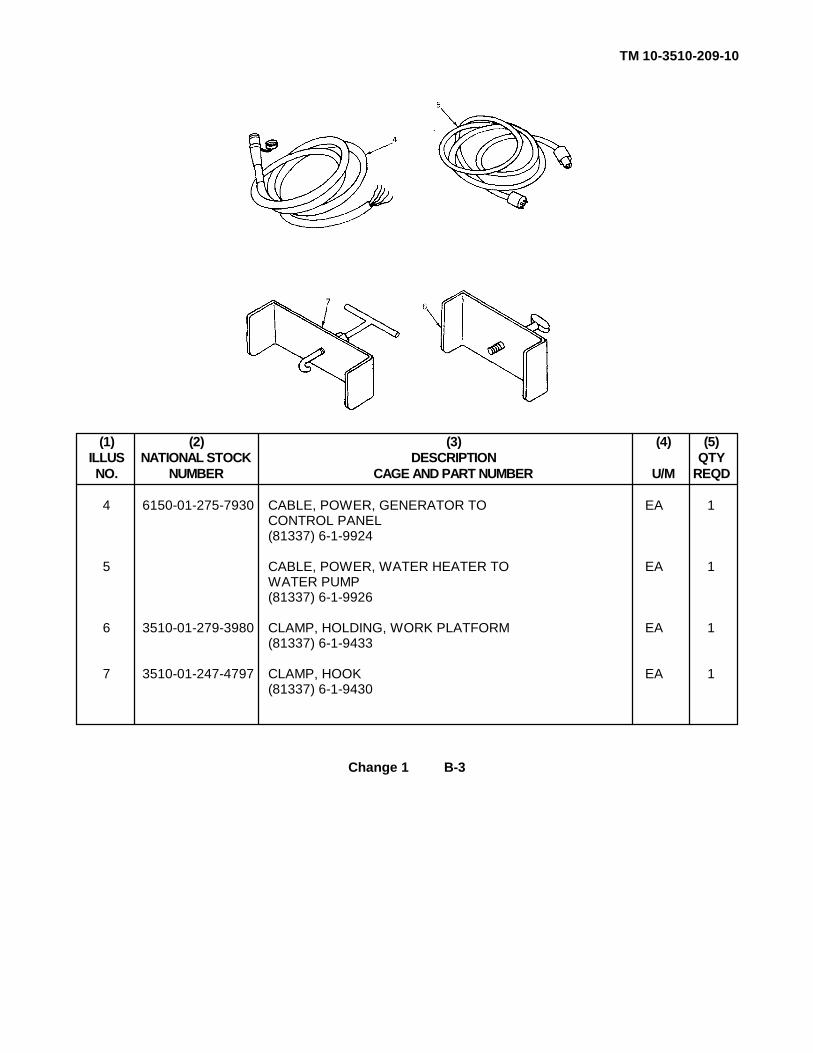
TM 10-3510-209-10
(1) (2) (3) (4) (5)ILLUS NATIONAL STOCK DESCRIPTION QTYNO. NUMBER CAGE AND PART NUMBER U/M REQD
4 6150-01-275-7930 CABLE, POWER, GENERATOR TO EA 1CONTROL PANEL(81337) 6-1-9924
5 CABLE, POWER, WATER HEATER TO EA 1WATER PUMP(81337) 6-1-9926
6 3510-01-279-3980 CLAMP, HOLDING, WORK PLATFORM EA 1(81337) 6-1-9433
7 3510-01-247-4797 CLAMP, HOOK EA 1(81337) 6-1-9430
Change 1 B-3

TM 10-3510-209-10
(1) (2) (3) (4) (5)ILLUS NATIONAL STOCK DESCRIPTION QTYNO. NUMBER CAGE AND PART NUMBER U/M REQD
8 PANEL, SOUND DEADENING
3510-01-245-6934 SIDE PANEL SMALL EA 2
(81337) 1-6-0114
5640-01-285-4288 SIDE PANEL LARGE EA 1(81337) 6-2-2400
3510-01-246-9256 TOP PANEL EA 3(81337) 1-6-0118
9 3510-01-242-7258 STEP ASSY, PLATFORM EA 2(81337) 6-1-9949
10 3510-01-246-9258 STRUT ASSY, TARP EA 2(81337) 6-1-9416
B-4 Change 1

TM 10-3510-209-10
(1) (2) (3) (4) (5)ILLUS NATIONAL STOCK DESCRIPTION QTYNO. NUMBER CAGE AND PART NUMBER U/M REQD
11 3510-01-253-4303 TARPAULIN EA 1(81337) 6-1-9962
12 3510-01-250-3645 WORKSTAND STORAGE SUPPORTS EA 2(81337) 6-1-9859
13 4510-01-245-6936 WATER PUMP ASSY EA 1(81337) 6-1-9932
Change 1 B-5

TM 10-3510-209-10
(1) (2) (3) (4) (5)ILLUS NATIONAL STOCK DESCRIPTION QTYNO. NUMBER CAGE AND PART NUMBER U/M REQD
14 WATER PUMP HOLDDOWN ASSY EA 2(81337) 6-1-9443
15 WORK PLATFORM ASSY, WASHER (HIGH) EA 1(81337) 6-1-8356WORK PLATFORM ASSY, DRYER (LOW) EA 1(81337) 6-2-2411
16 WORK PLATFORM ASSY, SHORT EA 1(81337) 6-1-9855
17 TWO STEP ASSY EA 1(81337) 6-2-2403
B-6 Change 1
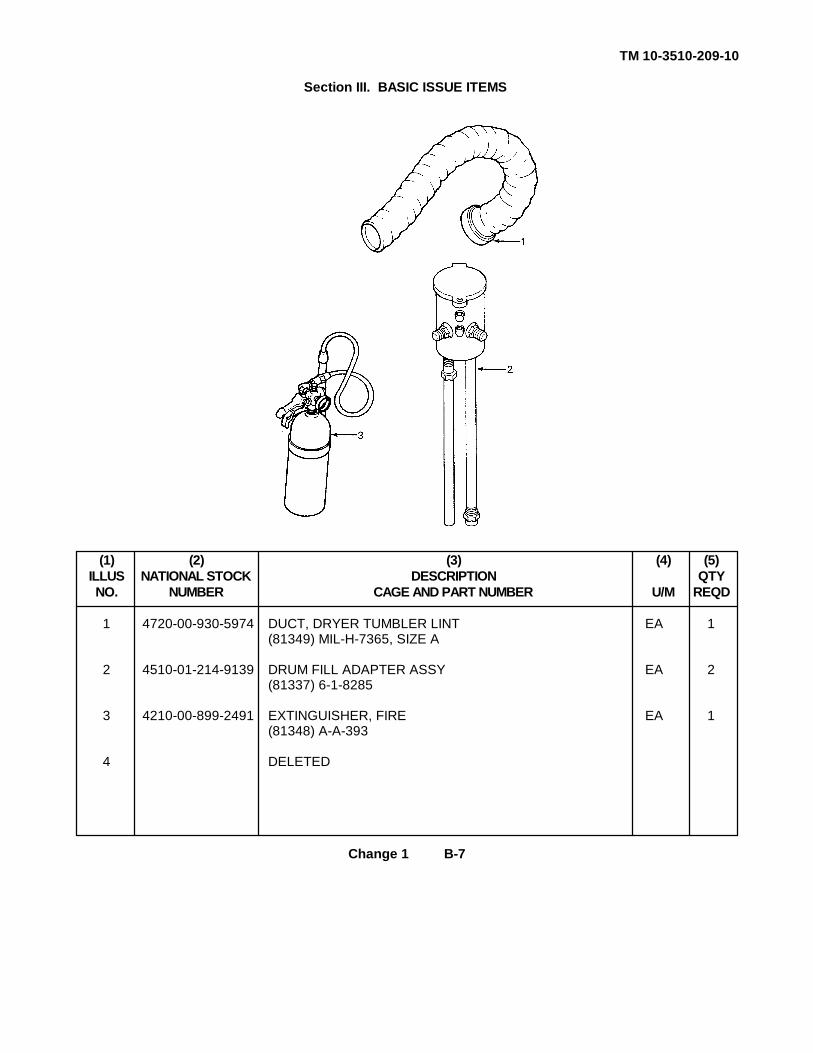
TM 10-3510-209-10
Section III. BASIC ISSUE ITEMS
(1) (2) (3) (4) (5)ILLUS NATIONAL STOCK DESCRIPTION QTYNO. NUMBER CAGE AND PART NUMBER U/M REQD
1 4720-00-930-5974 DUCT, DRYER TUMBLER LINT EA 1(81349) MIL-H-7365, SIZE A
2 4510-01-214-9139 DRUM FILL ADAPTER ASSY EA 2(81337) 6-1-8285
3 4210-00-899-2491 EXTINGUISHER, FIRE EA 1(81348) A-A-393
4 DELETED
Change 1 B-7

TM 10-3510-209-10
(1) (2) (3) (4) (5)ILLUS NATIONAL STOCK DESCRIPTION QTYNO. NUMBER CAGE AND PART NUMBER U/M REQD
5 4720-00-064-0832 HOSE, FUEL RETURN EA 4(81337) 6-1-9836-65
6 4720-00-202-6721 HOSE, GARDEN, 6-FOOT EA 1(81348) L-H-520-6
7 5975-00-878-3791 GROUND ROD ASSY, SECTIONAL, EA 1W/ATTACHMENTSMIL-R-11461 (81349)
8 4720-01-B76-7729 HOSE ASSY, DRAIN, EXTRACTOR-TO- EA 1DRAIN FIELD(81337) 6-1-9946-3
B-8 Change 1

TM 10-3510-209-10
(1) (2) (3) (4) (5)ILLUS NATIONAL STOCK DESCRIPTION QTYNO. NUMBER CAGE AND PART NUMBER U/M REQD
9 4720-01-B76-7728 HOSE ASSY, PRE-EXTRACT DRAIN EA 1(81337) 6-1-9946-2
10 4720-00-707-1106 HOSE ASSY, SOURCE-TO-WATER-PUMP EA 2AND WATER-PUMP-TO-HEATER(81337) 6-1-746-7
11 4720-01-B76-8033 HOSE ASSY, WATER-HEATER-TO-WASHER EA 1(81337) 6-1-9946-1
12 4720-01-B76-7730 HOSE ASSY, MAIN DRAIN EA 1(81337) 6-1-9995-4
Change 1 B-9

TM 10-3510-209-10
(1) (2) (3) (4) (5)ILLUS NATIONAL STOCK DESCRIPTION QTYNO. NUMBER CAGE AND PART NUMBER U/M REQD
13 4720-00-903-4148 DUCT, GENERATOR EXHAUST EA 2(81337) 6-2-2419
14 4520-00-950-6359 DUCT, WATER HEATER EXHAUST EA 2(81337) 6-2-2427
15 4720-01-261-6815 DUCT, DRYER EXHAUST EA 1(81337) 6-2-2303
16 LUBRICATION ORDER EA 1LO 10-3510-209-12
17 4720-00-729-5334 HOSE, GARDEN, 50-FOOT EA 1(81348) L-H-520
B-10 Change 1

TM 10-3510-209-10
(1) (2) (3) (4) (5)ILLUS NATIONAL STOCK DESCRIPTION QTYNO. NUMBER CAGE AND PART NUMBER U/M REQD
18 4730-01-249-1969 STRAINER, SUCTION EA 1(81337) 6-1-8359
19 OPERATOR'S MANUAL EA 1TM 10-3510-209-10
20 MAINTENANCE REPAIR PARTS AND EA 1SPECIAL TOOLS LISTS MANUALTM 10-3510-209-24P
21 MAINTENANCE MANUAL EA 1TM 10-3510-209-24
22 3510-01-283-4610 PRE-CUT WASHER CONTROL CHARTS SE 1
Change 1 B-11

TM 10-3510-209-10
(1) (2) (3) (4) (5)ILLUS NATIONAL STOCK DESCRIPTION QTYNO. NUMBER CAGE AND PART NUMBER U/M REQD
23 6640-00-063-7879 FUNNEL, COMMON LAB, EA 1PLASTIC, POLYETHYLENE802PE (95352)
24 5120-01-013-1676 SLIDE HAMMER, GROUND ROD EA 1EMPLACEMENT(45225) P74-144
25 5120-01-278-0352 PLIERS, SLIP JOINT: EA 110-IN., ADJUSTABLE(80212) P489
26 5120-01-234-8912 SCREWDRIVER, CROSS TIP: EA 16-IN.(C7127) SSDP63
B-12

TM 10-3510-209-10
(1) (2) (3) (4) (5)ILLUS NATIONAL STOCK DESCRIPTION QTYNO. NUMBER CAGE AND PART NUMBER U/M REQD
27 5120-00-237-6985 SCREWDRIVER, FLAT TIP: EA 18-IN.
28 5120-00-227-7334 SCREWDRIVER, FLAT TIP: EA 110-IN.
29 5120-00-240-5328 WRENCH, OPEN END, ADJUSTABLE: EA 18-IN.
30 5120-01-264-3796 WRENCH, OPEN END, ADJUSTABLE: EA 112-IN.
31 LADDER ASSY EA 1(81337) 6-2-2426
Change 1 B-13/(B-14 Blank)
TM 10-3510-209-10
APPENDIX C
EXPENDABLE/DURABLE SUPPLIES AND MATERIALS LIST
Section I. INTRODUCTION
C-1. SCOPE. This appendix lists expendable supplies and materials you will need to operate and maintainthe laundry unit. This listing is for informational purposes only and is not authority to requisition the listeditems. These items are authorized to you by CTA 50-970, Expendable/Durable Items (Except Medical, Class V,Repair Parts, and Heraldic Items), or CTA 8-100, Army Medical Department Expendable/Durable Items.
C-2. EXPLANATION OF COLUMNS.
a. Column(1) - Item Number. This number is assigned to the entry in the listing and is referenced inthe narrative instructions to identify the material, e.g., Use cleaning compound (item 5, app D).
b. Column(2) - Level. This column identifies the lowest level of maintenance that requires the listeditem.
C - Operator/Crew0 - UnitF - Intermediate Direct SupportH - Intermediate General Support
c. Column(3) - National Stock Number. This is the National stock number assigned to the item; use itto request or requisition the item.
d. Column(4) - Description. Indicates the Federal item name and, if required, a description to identifythe item. The last line for each item indicates the Government and Commercial Entity (CAGE) in parentheses,followed by the part number.
e. Column(5) - Unit of Measure (U/M). Indicates the measure used in performing the actualmaintenance function. This measure is expressed by a two-character alphabetical abbreviation (e.g., ea, in.,pr). If the unit of measure differs from the unit of issue, requisition the lowest unit of issue that will satisfy yourrequirements.
C-1
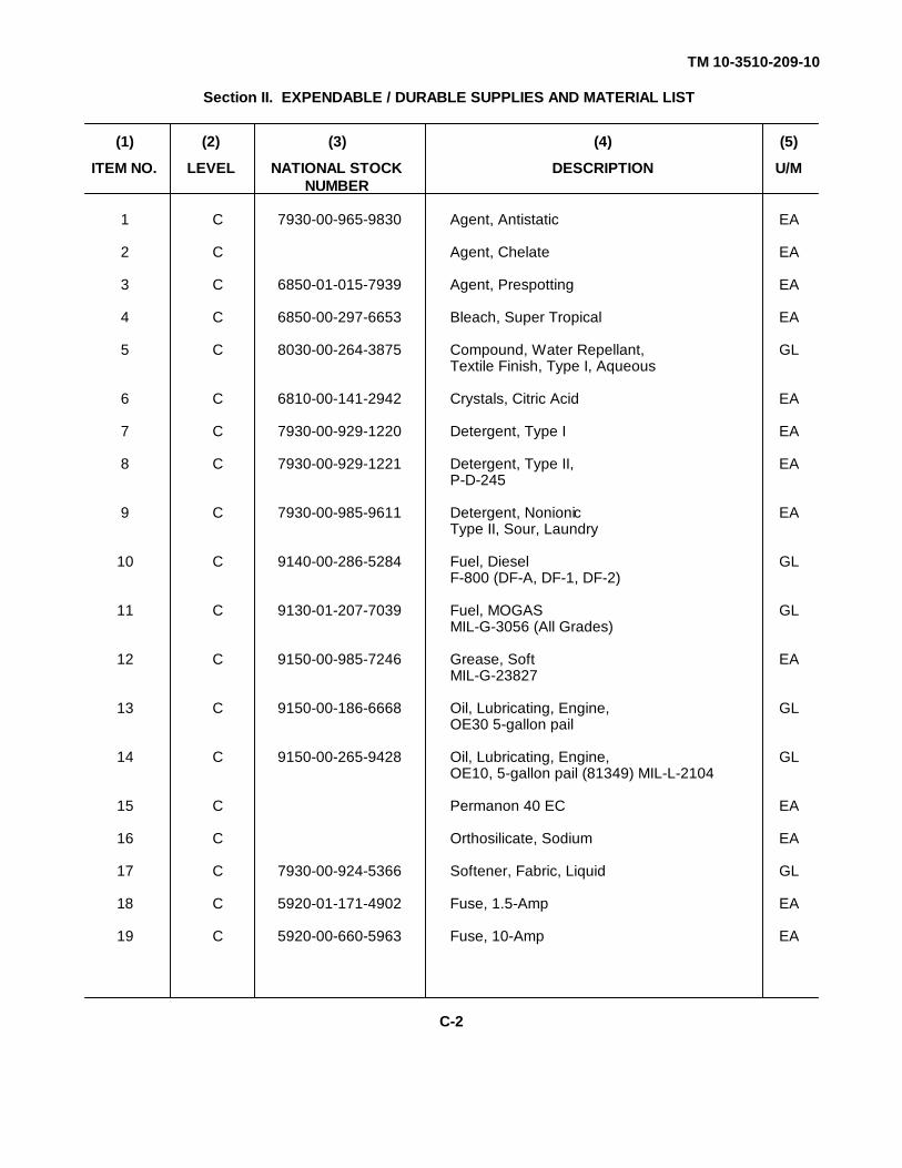
TM 10-3510-209-10
Section II. EXPENDABLE / DURABLE SUPPLIES AND MATERIAL LIST
(1) (2) (3) (4) (5)
ITEM NO. LEVEL NATIONAL STOCK DESCRIPTION U/MNUMBER
1 C 7930-00-965-9830 Agent, Antistatic EA
2 C Agent, Chelate EA
3 C 6850-01-015-7939 Agent, Prespotting EA
4 C 6850-00-297-6653 Bleach, Super Tropical EA
5 C 8030-00-264-3875 Compound, Water Repellant, GLTextile Finish, Type I, Aqueous
6 C 6810-00-141-2942 Crystals, Citric Acid EA
7 C 7930-00-929-1220 Detergent, Type I EA
8 C 7930-00-929-1221 Detergent, Type II, EAP-D-245
9 C 7930-00-985-9611 Detergent, Nonionic EAType II, Sour, Laundry
10 C 9140-00-286-5284 Fuel, Diesel GLF-800 (DF-A, DF-1, DF-2)
11 C 9130-01-207-7039 Fuel, MOGAS GLMIL-G-3056 (All Grades)
12 C 9150-00-985-7246 Grease, Soft EAMIL-G-23827
13 C 9150-00-186-6668 Oil, Lubricating, Engine, GLOE30 5-gallon pail
14 C 9150-00-265-9428 Oil, Lubricating, Engine, GLOE10, 5-gallon pail (81349) MIL-L-2104
15 C Permanon 40 EC EA
16 C Orthosilicate, Sodium EA
17 C 7930-00-924-5366 Softener, Fabric, Liquid GL
18 C 5920-01-171-4902 Fuse, 1.5-Amp EA
19 C 5920-00-660-5963 Fuse, 10-Amp EA
C-2

TM 10-3510-209-10
APPENDIX D
ADDITIONAL AUTHORIZATION LIST
Section I. INTRODUCTION
D-1. SCOPE. This appendix lists additional items that are authorized for the support of the laundry unit.
D-2. GENERAL. The list identifies items that do not have to accompany the laundry unit and that do not haveto be turned in with it. These items are all authorized for use by CTA, MTOE, TDA, or JTA.
D-3. EXPLANATION OF LIST INGS. National stock numbers, descriptions, and quantities are provided tohelp you identify and request the additional items required to support this equipment. The items are listed inalphabetical sequence by item name under the type document (i.e., CTA, MTOE, TDA, or JTA) whichauthorizes the item(s) to you.
Change 1 D-1
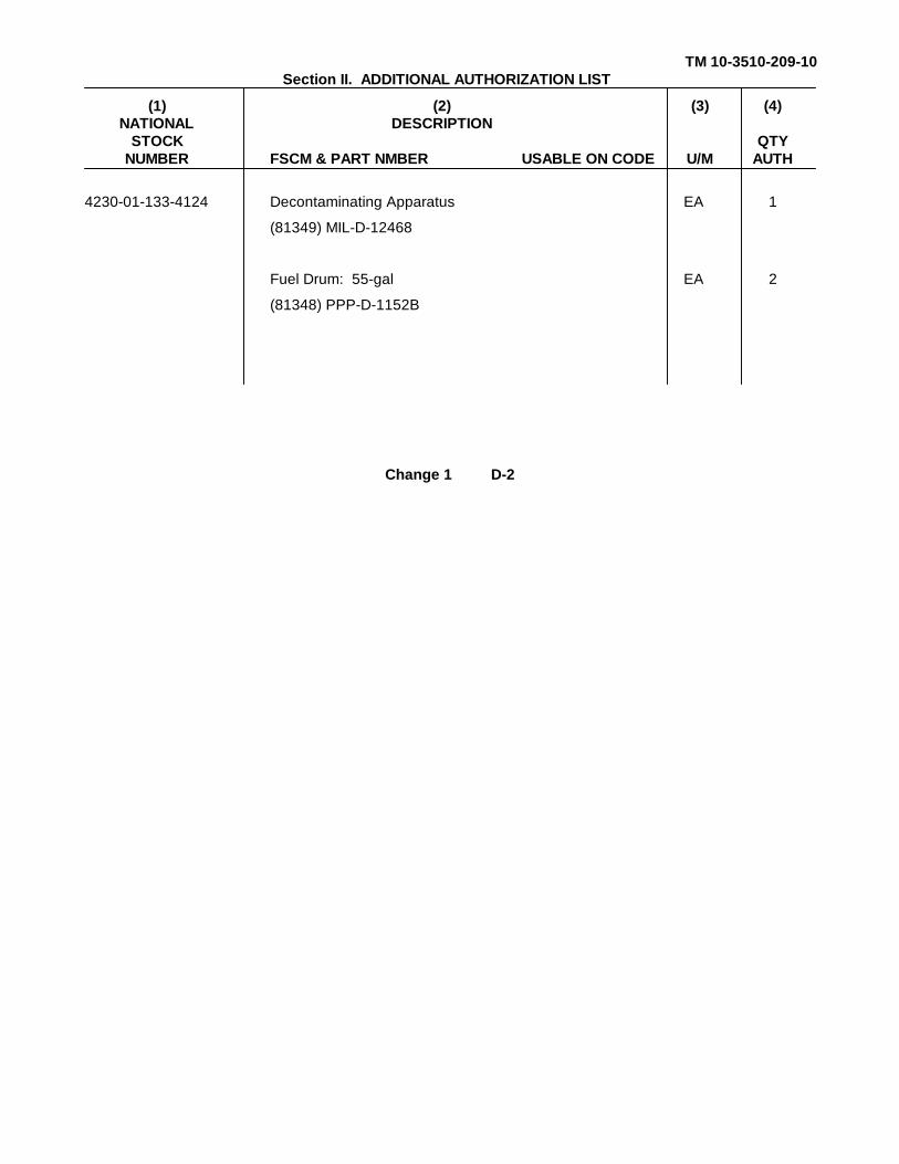
TM 10-3510-209-10Section II. ADDITIONAL AUTHORIZATION LIST
(1) (2) (3) (4)NATIONAL DESCRIPTION
STOCK QTYNUMBER FSCM & PART NMBER USABLE ON CODE U/M AUTH
4230-01-133-4124 Decontaminating Apparatus EA 1
(81349) MIL-D-12468
Fuel Drum: 55-gal EA 2
(81348) PPP-D-1152B
Change 1 D-2

TM 10-3510-209-10
INDEX
Subject Page
A
Abbreviations................................ ................................ ................................ .................... 1-2Additional Authorization List (AAL)................................ ................................ ....................D-1Assembly, site selection; setup and................................ ................................ ..................2-30
B
Basic issue items................................ ................................ ................................ ..............B-7
C
Checks and services, preventive maintenance................................ ................................ .2-14Components of end item and basic issue items................................ ................................ B-1Components, major, location and description................................ ................................ ....1-4Contents, table of ................................ ................................ ................................ ............. iControl finger functions................................ ................................ ................................ .....2-58Controls and indicators, description and use of................................ ................................ .2-1Cross-reference list, nomenclature................................ ................................ ................... 1-2
D
Data, equipment................................ ................................ ................................ ...............1-7Data plate................................ ................................ ................................ ......................... 2-76Decals and instruction plates, operating instructions on................................ .................... 2-74Description of major components, location and................................ ................................ .1-4Dust or sand, operation in................................ ................................ ................................ .2-79
E
Emergency procedures................................ ................................ ................................ .....2-79Equipment description:
Equipment purpose, capabilities, and features................................ .......................... 1-3Location and description of major components................................ .......................... 1-4
Equipment improvement recommendations' (EIR), reporting................................ ............1-1Equipment:
Capabilities ................................ ................................ ................................ ...............1-3Data................................ ................................ ................................ .......................... 1-7Feature ................................ ................................ ................................ ..................... 1-3Purpose ................................ ................................ ................................ .................... 1-3
Expendable supplies and materials list................................ ................................ .............C-2Extreme cold, operation in................................ ................................ ................................ 2-78
F
Features of equipment................................ ................................ ................................ ......1-3Finger functions, control ................................ ................................ ................................ ...2-58Forms and records, maintenance................................ ................................ ...................... 1-1
Change 1 INDEX 1

TM 10-3510-209-10
Subject Page
G
General information:Abbreviations................................ ................................ ................................ ............1-2Equipment data................................ ................................ ................................ .........1-7Hand receipt (HR) manuals................................ ................................ ....................... 1-1Maintenance forms and records................................ ................................ ................1-1Metric system................................ ................................ ................................ ............1-1Nomenclature cross-reference list................................ ................................ .............1-2Reference information................................ ................................ ............................... 1-2Scope ................................ ................................ ................................ ....................... 1-1Warranty information ................................ ................................ ................................ 1-1
General maintenance procedures................................ ................................ ..................... 2-16Generator maintenance (Refer to TM 5-6115-585-12)Glossary ................................ ................................ ................................ ........................... 1-2
H
Hand receipt (HR) manuals................................ ................................ ............................... 1-1How to use this manual................................ ................................ ................................ ..... iii
I
Indicators, description and use of operator's controls................................ ........................ 2-1Indicators, location and use of controls and................................ ................................ ......2-3Information, reference ................................ ................................ ................................ ......1-2Information, warranty................................ ................................ ................................ ........1-1Index, symptom................................ ................................ ................................ ................3-2Instruction plates, operating instructions on decals and................................ ..................... 2-74
L
List, nomenclature cross-reference................................ ................................ ................... 1-2List of weights................................ ................................ ................................ ................... 2-63Location and description of major components................................ ................................ .1-4Location and use of controls and indicators................................ ................................ .......2-1Lubrication instructions................................ ................................ ................................ .....3-1Lubrication references................................ ................................ ................................ ......3-1
M
Maintenance:General maintenance procedures................................ ................................ ..............2-14Preventive checks and service................................ ................................ ..................2-14
Maintenance forms and records................................ ................................ ........................ 1-1Maintenance instructions:
Generator (Refer to TM 5-6115-585-12)Lubrication instructions................................ ................................ .............................. 3-1Maintenance procedures................................ ................................ ........................... 3-13Trailer assembly (Refer to TM 9-2330-376-14&P)Troubleshooting procedures................................ ................................ ...................... 3-1
INDEX 2

TM 10-3510-209-10
Subject Page
M (cont)
Major components, location and description................................ ................................ .....1-4Manuals, hand receipt (HR)................................ ................................ .............................. 1-1Materials, expendable................................ ................................ ................................ .......C-2Metric system ................................ ................................ ................................ ................... 1-1Movement, preparation for................................ ................................ ................................ 2-69
N
Nomenclature cross-reference list................................ ................................ ..................... 1-2
O
Operating instructions:Description and use of controls and indicators................................ ........................... 2-1On decals and instruction plate................................ ................................ .................2-74Operation of generator set (Refer to TM 5-6115-585-12)Operation under unusual conditions................................ ................................ ..........2-78Operation under usual conditions................................ ................................ ..............2-30Preventive maintenance checks and services (PMCS)................................ ..............2-14
Operating procedures................................ ................................ ................................ .......2-9Operation under unusual conditions:
Emergency procedures................................ ................................ ............................. 2-78Operation in extreme cold................................ ................................ ......................... 2-78Operation in dust or sand................................ ................................ .......................... 2-79Operation in saltwater areas................................ ................................ ...................... 2-79Operation in snow or mud................................ ................................ ......................... 2-79
Operation under usual conditions:Introduction................................ ................................ ................................ ...............2-30Controls and indicators, description and use of................................ .......................... 2-1
P
Preparation for movement................................ ................................ ................................ 2-69Preparation for use................................ ................................ ................................ ...........2-47Preventive maintenance checks and services................................ ................................ ...2-14Principles of operation................................ ................................ ................................ ......1-9Procedures, emergency................................ ................................ ................................ ....2-79Procedures, operating................................ ................................ ................................ .......2-9Purpose of equipment................................ ................................ ................................ .......1-3
R
Records, maintenance forms and................................ ................................ ..................... 1-1Reference information................................ ................................ ................................ ......1-2References................................ ................................ ................................ ....................... A-1References, lubrication................................ ................................ ................................ .....3-1Reporting errors and recommending improvements................................ .......................... iReporting equipment improvement recommendations................................ ...................... 1-1
INDEX 3

TM 10-3510-209-10
Subject Page
S
Saltwater areas, operation................................ ................................ ................................ 2-79Service:
Preventive maintenance checks and services (PMCS)................................ ..............2-14Site selection, setup, and assembly................................ ................................ ..................2-30Supplies, expendable................................ ................................ ................................ .......C-2Symptom index ................................ ................................ ................................ ................3-2System, metric ................................ ................................ ................................ .................1-1
T
Table of contents................................ ................................ ................................ .............. iTechnical principles of operation:
Air compressor................................ ................................ ................................ ..........1-10Dryer................................ ................................ ................................ ......................... 1-10Extractor ................................ ................................ ................................ ................... 1-10Generator and power distribution box................................ ................................ ........1-10Washer ................................ ................................ ................................ ..................... 1-9Water heater................................ ................................ ................................ .............1-10Water pump................................ ................................ ................................ ..............1-10
Trailer assembly maintenance (Refer to TM 9-2330-376-14&P)Troubleshooting:
Introduction................................ ................................ ................................ ...............3-1Procedures................................ ................................ ................................ ................3-1
U
Use of controls and indicators, location and................................ ................................ ......2-1Use, preparation for................................ ................................ ................................ ..........2-47
W
Warnings, summary................................ ................................ ................................ ..........aWarranty information................................ ................................ ................................ ........1-1Weights, list of................................ ................................ ................................ ..................2-63
INDEX 4
TM 10-3510-209-10
By Order of the Secretary of the Army:CARL E. VUONO
General, United States ArmyChief of Staff
Official:
R. L. DILWORTHBrigadier General, United States Army
The Adjutant General
DISTRIBUTION:To be distributed in accordance with DA Form 12-25A, Operator's Maintenance requirements for Laundry
Unit, Single Trailer Mounted, with Canvas Cover, Type M532
U.S. GOVERNMENT PRINTING OFFICE: 1993 0 - 342-421 (61731)

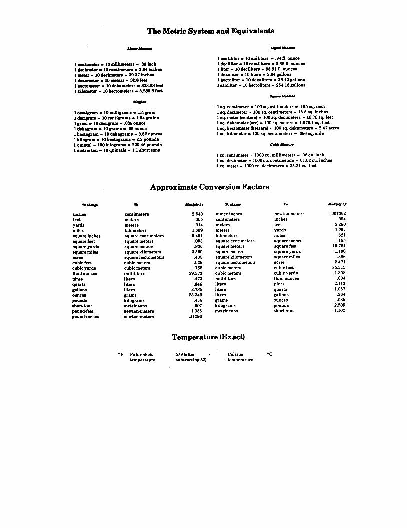

PIN: 063932-000

This fine document...
Was brought to you by me:
Liberated Manuals -- free army and government manuals
Why do I do it? I am tired of sleazy CD-ROM sellers, who take publicly available information, slap “watermarks” and other junk on it, and sell it. Those masters of search engine manipulation make sure that their sites that sell free information, come up first in search engines. They did not create it... They did not even scan it... Why should they get your money? Why are not letting you give those free manuals to your friends?
I am setting this document FREE. This document was made by the US Government and is NOT protected by Copyright. Feel free to share, republish, sell and so on.
I am not asking you for donations, fees or handouts. If you can, please provide a link to liberatedmanuals.com, so that free manuals come up first in search engines:
<A HREF=http://www.liberatedmanuals.com/>Free Military and Government Manuals</A>
– SincerelyIgor Chudovhttp://igor.chudov.com/
– Chicago Machinery Movers