tlv320dac3100 test for detection of open loads
TRANSCRIPT

MICBIAS
VOL/MICDET
SPKM
SPKP
Class Ddriver
DAC3100
150 µH
150 µH
4.7 µF
4.7 µF
220 µF
220 µF
100 kΩ
100 kΩ
100 kΩ
10 kΩR1
R2
R3
8- or 4-speaker
Ω
Application ReportSLAA540A–June 2012–Revised March 2013
TLV320DAC3100 Test for Detection of Open LoadsWen-Shin Wang ............................................................................................ MSA Catalog Applications
ABSTRACT
An open load detection test can be implemented using headset-detection test of the TLV320DAC3100.This application note provides a summary of the headset-detection test with the TLV320DAC3100 EVMand how to use the headset-detection test to detect an open load.
1 Test for Detection of Headsets
Headset detection is normally used to determine if a headset has been inserted into the EVM. It can alsodetermine the type of headset, either with or without a microphone. This detection is accomplished byobserving the voltage on the MICDET input. See Figure 1 for schematic representation and Table 1 forthreshold voltages.
Table 1. Voltage Threshold for Detection of Headsets
REGISTER 67/BITSDESCRIPTION VOLTAGE THRESHOLD
D6-D5
00 No headset detected MICDET > approx. 0.91 × MICBIAS (1) (2)
01 Headset without microphone detected MICDET < approx. 0.1 × MICBIAS
11 Headset with microphone detected Approx. 0.1 × MICBIAS < MICDET < approx. 0.9 ×MICBIAS
(1) MICBIAS by default is powered to AVDD and can also be powered to 2.5 V, 2 V, or powered down.(2) If MICBIAS is powered down, the voltage threshold is based on DVDD.
Figure 1. Test Layout for Detection of Open Loads
1SLAA540A–June 2012–Revised March 2013 TLV320DAC3100 Test for Detection of Open LoadsSubmit Documentation Feedback
Copyright © 2012–2013, Texas Instruments Incorporated

MICBIAS
VOL/MICDET
SPKM
SPKP
Class Ddriver
DAC3100
150 µH
150 µH
4.7 µF
4.7 µF
220 µF
220 µF
100 kΩ
100 kΩ
100 kΩ
10 kΩ
8- or 4-speaker
Ω
MICBIAS
VOL/MICDET
SPKM
SPKP
Class Ddriver
DAC3100
150 µH
150 µH
4.7 µF
4.7 µF
220 µF
220 µF
100 kΩ
100 kΩ
100 kΩ
10 kΩ
8- or 4-speaker
Ω
2 3MICDET MICBIAS
1 2 3
MICDET
MICDET
MICDET
R RV V
R R R
100 k 100 k V 3.3 V
100 k 100 k 100 k
2V 3.3 V
3
V 2. V2
æ ö+= ç ÷
+ +è ø
æ öW + W= ç ÷
W + W + Wè ø
æ ö= ç ÷
è ø
=
Test for Detection of Open Loads www.ti.com
For the open load test, the feature for headset detection makes a voltage measurement that candetermine the continuity of the speaker circuit. The voltage on the MICDET pin is set by the dividerconsisting of R1, R2, R3, and the resistance of the speaker (see Figure 1). During an open circuit, theresistance of the speaker circuit is near infinity; therefore, the MICDET voltage is simply pulled toMICBIAS. During normal conditions, the resistance of the speaker circuit is near zero compared to theresistance of R1, R2, and R3, and thus the MICDET voltage is calculated according to formula. SeeEquation 1 for the calculation of MICDET.
(1)
The detection feature must be specifically activated, because it is not enabled by default. To enableheadset detection, see Section 5.5.5 in the data manual (SLAS671).
2 Test for Detection of Open Loads
The layout of the test for detection of open loads is as seen in Figure 1.
When a load is detected, MICDET is pulled below the 0.91 × MICBIAS threshold (≈ 2.2 V in this case),which allows for a headset to be detected. When the load is disconnected, MICDET is pulled to MICBIAS,and no headset is detected. See Figure 2 for an example. Figure 3 shows the register values providedwhen using the EVM GUI Command Buffer prompt.
Figure 2. Voltage Flow of MICDET With and Without an Open Load
2 TLV320DAC3100 Test for Detection of Open Loads SLAA540A–June 2012–Revised March 2013Submit Documentation Feedback
Copyright © 2012–2013, Texas Instruments Incorporated

0 L
L
1C
R 2
1C
*R
2 f 22
1C
2 (6 kHz) 4 2
C 4.689 μF 4.7 μF
=w ´ ´
=æ ö
p ´ ´ç ÷ç ÷è ø
=p ´ W ´
= »
www.ti.com Test for Detection of Open Loads
Figure 3. Register Values From the Command Prompt
The resistors between MICBIAS to MICDET to ground must be high, such as 100 kΩ, to reduce losses,limit the current, and ensure that the output is not being driven back into the input. The resistor fromMICBIAS to ground can be any value, such as 10 kΩ, to complete the current path to ground.
The 220-µF capacitors are necessary to minimize dc bias of the detection circuit. These capacitors mustbe large in order to minimize any contribution to the series impedance of the speaker circuit.
The inductors, and specifically the 4.7-µF capacitors, act as output filters. Because the TLV320 familyuses BD modulation, a capacitor (CBTL) is not needed between SPKP and SPKM as it usually is for ADmodulation.
In Figure 1, the output filter (2nd-order Butterworth low-pass) is set to a cutoff frequency of 6 kHz with an 8-Ω load. See Equation 2 and Equation 3 for calculating the C and L values.
(2)
* RL becomes RL / 2 to account for analysis of the differential mode. See Figure 4 for the equivalent circuit.
3SLAA540A–June 2012–Revised March 2013 TLV320DAC3100 Test for Detection of Open LoadsSubmit Documentation Feedback
Copyright © 2012–2013, Texas Instruments Incorporated

L
0
L
R 2L
R 2
2L
2 f
4 2L
2 (6 kHz)
L 150.053 H 150 H
´=
w
æ ö´ç ÷ç ÷
è ø=p
W´=
p
= m » mµ µ
V +out
Vout–
Cg
Cg
LBTL
LBTL
V +in
Vin–
R /2BTL
R /2BTL
Test Procedure for Detection of Open Loads www.ti.com
Figure 4. Equivalent Circuit for Analysis of the Differential Mode
(3)
Further details regarding BD modulation and values for the inductors and capacitors can be found in:Class-D LC Filter Design (SLOA119).
3 Test Procedure for Detection of Open Loads
The following steps use the TLV320DAC3100 EVM and its corresponding GUI. A USB-to-mini USBconnector is needed to connect the EVM to a computer or laptop.
3.1 Setup Considerations
To download the software, go to the TLV320DAC3120 EVM product folder under Related Products.
To install the GUI, first download the software. Then attach the EVM to the computer using the USB cable.Next, open the .exe file named CodecControl and choose TLV320AIC3100EVM-U when the Select EVMpanel appears.
For hardware considerations, all of the jumpers on the EVM must be taken off the headers (W1, W2, W3),because the layout is manually pulling MICDET to MICBIAS. See Figure 5 for an example. Table 2 alsolists the functionality of each header.
4 TLV320DAC3100 Test for Detection of Open Loads SLAA540A–June 2012–Revised March 2013Submit Documentation Feedback
Copyright © 2012–2013, Texas Instruments Incorporated

www.ti.com Test Procedure for Detection of Open Loads
Figure 5. EVM Board With No Jumpers
Table 2. Description of Headers
HEADER DESCRIPTION
W1 (pins 1–2) Analog volume control
W1(pins 2–3) Microphone detection
W2 Apply right-channel MICBIAS voltage to microphone connector
W3 Apply left-channel MICBIAS voltage to microphone connector
One can use pin 2 on header W1 to measure MICDET and R17 (on the back of the EVM) to measureMICBIAS.
3.2 Steps in the GUI for Detection of Open Loads
There are four steps when using the GUI to test for open loads, assuming the speaker is alreadyconnected to the EVM.
1. Enable headset detection (Page 0/Register 67, bit D7 should be set to 1).
2. Read the register (Register should read E0/A0).
3. Disconnect the speaker by removing leads.
4. Read the register (Register should read 80).
3.2.1 Enable Headset Detection
Headset detection can be enabled through either Register Inspector or Command. It is not necessary toenable headset detection using both Register Inspector and Command. Once changes have been enabledusing either process, the GUI automatically updates the information, which is reflected in the other.
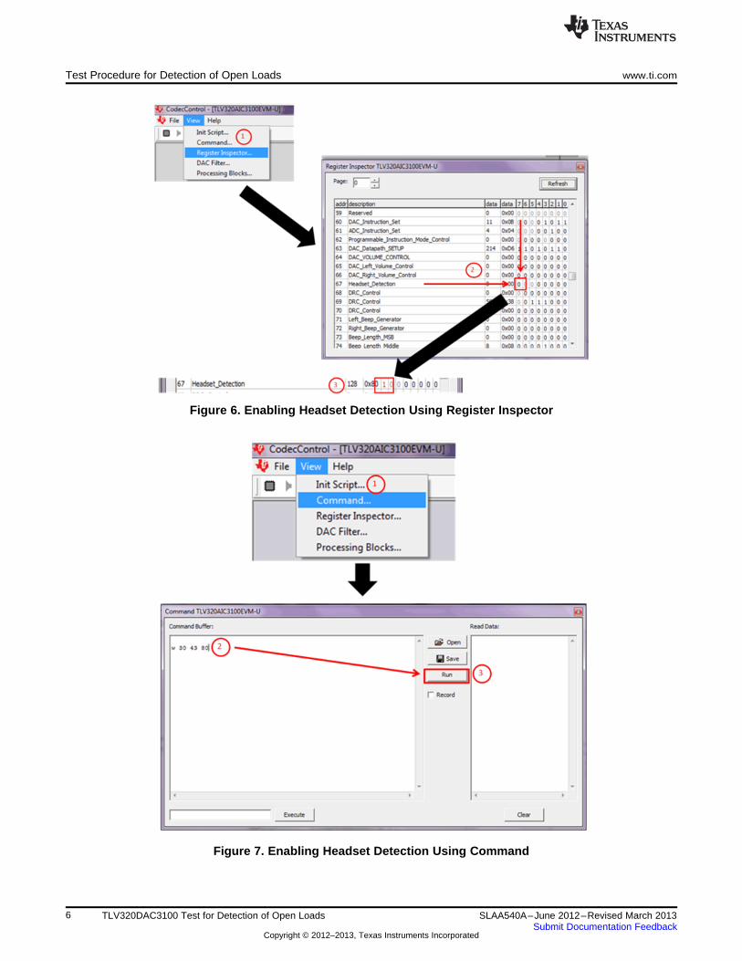
To enable headset detection through Register Inspector, go to View → Register Inspector. Next, scrolldown to Register 67 and click on the 0 in column 67 to change it to a 1. The number turns red whentransitioning from one value to another to indicate the change. The advantage in using this process isease of use.
To enable headset detection through Command, go to View → Command. Then in the command buffer,type w 30 43 80 and click Run. w indicates write and 30,43, and 80 indicate the device address, register(Register 67 in this instance), and data value written in hex, respectively. The advantage in using thisprocess is the ability to insert multiple manual instructions as desired.
See Figure 6 and Figure 7 to enable headset detection using Register Inspector and Command,respectively.
5SLAA540A–June 2012–Revised March 2013 TLV320DAC3100 Test for Detection of Open LoadsSubmit Documentation Feedback
Copyright © 2012–2013, Texas Instruments Incorporated
Test Procedure for Detection of Open Loads www.ti.com
Figure 6. Enabling Headset Detection Using Register Inspector
Figure 7. Enabling Headset Detection Using Command
6 TLV320DAC3100 Test for Detection of Open Loads SLAA540A–June 2012–Revised March 2013Submit Documentation Feedback
Copyright © 2012–2013, Texas Instruments Incorporated

www.ti.com Other Considerations
3.2.2 Read Register
The easiest way to read a register value is through Command. In the text box, write r 30 43 01. r indicatesread and 30 and 43 indicate the device address and register (Register 67 in this instance) once again. 01indicates the number of bytes read from the register. Click on Execute and the data appears in the ReadData box. See Figure 8 for reading a register value from Command. Figure 3 shows the register valuestransitioning between detecting a speaker and an open load.
Figure 8. Reading a Register Using Command
4 Other Considerations
There are two factors to take into consideration when using the headset-detection circuitry: the capacitorsand the volume level of the device.
4.1 Capacitor Considerations
For capacitors considerations, see the 220-μF dc-blocking capacitors in Section 2. When pickingcapacitors, the larger the capacitor, the more efficiently DC bias is eliminated and there is less chance fora false reading; false reading meaning the register reads that a speaker is connected when it is actuallydisconnected and vice versa. However, the charge/discharge time is also longer. This timing means thatwhen the speaker is disconnected, it takes a longer period of time before MICDET reaches 0.91 xMICDET and is considered disconnected.
The same logic goes to smaller capacitors. While smaller capacitors will have faster charge/dischargetimes, and therefore, will detect a disconnected speaker more quickly; these caps will also block DC biasless efficiently with a greater chance for false readings.
Based off the headset-detection circuitry and using a Mirage 5.1 Nanosat speaker, the minimum capacitorvalue is 10-μF, though the capacitor value should be chosen based on the system and speakers used.
4.2 Volume Level Considerations
As the purpose of the capacitors is to block out DC bias, the AC signal will pass through the capacitorsinto the speakers. Therefore, some AC signal can also be seen on the MICDET pin. To ensure that theMICDET pin does not exceed abs max (AVDD + 0.3V, or 3.6V in this case), the AC signal on the MICDETpin needs to be limited to 0.3Vpeak at the most.
To help limit the AC signal seen on the MICDET pin, either the Class-D Speaker Driver, AnalogAttenuation, or both (see Figure 9) need to be moderated so that neither of the two are at the highestsetting. See Table 3 for a summary of Class-D Speaker Driver levels vs. Analog Attenuation levels as tonot exceed abs max rating for MICDET.
7SLAA540A–June 2012–Revised March 2013 TLV320DAC3100 Test for Detection of Open LoadsSubmit Documentation Feedback
Copyright © 2012–2013, Texas Instruments Incorporated

Summary www.ti.com
Figure 9. Volume Level Section of EVM GUI
Table 3. Class-D Speaker Driver and AnalogAttenuation Levels for MICDET
Class-D Speaker Driver (dB) Analog Attenuation (max) (dB)
6 0
12 0
18 -10
24 -10
5 Summary
Open loads can be detected using the EVM GUI by first enabling headset detect, then reading register 67.
Headset detection works by having MICDET pulled to MICBIAS. When a headset is inserted, MICDETdrops to ground. The test for detection of open loads works in the same way by using the function forheadset detection to indicate load connectivity.
8 TLV320DAC3100 Test for Detection of Open Loads SLAA540A–June 2012–Revised March 2013Submit Documentation Feedback
Copyright © 2012–2013, Texas Instruments Incorporated

IMPORTANT NOTICE
Texas Instruments Incorporated and its subsidiaries (TI) reserve the right to make corrections, enhancements, improvements and otherchanges to its semiconductor products and services per JESD46, latest issue, and to discontinue any product or service per JESD48, latestissue. Buyers should obtain the latest relevant information before placing orders and should verify that such information is current andcomplete. All semiconductor products (also referred to herein as “components”) are sold subject to TI’s terms and conditions of salesupplied at the time of order acknowledgment.
TI warrants performance of its components to the specifications applicable at the time of sale, in accordance with the warranty in TI’s termsand conditions of sale of semiconductor products. Testing and other quality control techniques are used to the extent TI deems necessaryto support this warranty. Except where mandated by applicable law, testing of all parameters of each component is not necessarilyperformed.
TI assumes no liability for applications assistance or the design of Buyers’ products. Buyers are responsible for their products andapplications using TI components. To minimize the risks associated with Buyers’ products and applications, Buyers should provideadequate design and operating safeguards.
TI does not warrant or represent that any license, either express or implied, is granted under any patent right, copyright, mask work right, orother intellectual property right relating to any combination, machine, or process in which TI components or services are used. Informationpublished by TI regarding third-party products or services does not constitute a license to use such products or services or a warranty orendorsement thereof. Use of such information may require a license from a third party under the patents or other intellectual property of thethird party, or a license from TI under the patents or other intellectual property of TI.
Reproduction of significant portions of TI information in TI data books or data sheets is permissible only if reproduction is without alterationand is accompanied by all associated warranties, conditions, limitations, and notices. TI is not responsible or liable for such altereddocumentation. Information of third parties may be subject to additional restrictions.
Resale of TI components or services with statements different from or beyond the parameters stated by TI for that component or servicevoids all express and any implied warranties for the associated TI component or service and is an unfair and deceptive business practice.TI is not responsible or liable for any such statements.
Buyer acknowledges and agrees that it is solely responsible for compliance with all legal, regulatory and safety-related requirementsconcerning its products, and any use of TI components in its applications, notwithstanding any applications-related information or supportthat may be provided by TI. Buyer represents and agrees that it has all the necessary expertise to create and implement safeguards whichanticipate dangerous consequences of failures, monitor failures and their consequences, lessen the likelihood of failures that might causeharm and take appropriate remedial actions. Buyer will fully indemnify TI and its representatives against any damages arising out of the useof any TI components in safety-critical applications.
In some cases, TI components may be promoted specifically to facilitate safety-related applications. With such components, TI’s goal is tohelp enable customers to design and create their own end-product solutions that meet applicable functional safety standards andrequirements. Nonetheless, such components are subject to these terms.
No TI components are authorized for use in FDA Class III (or similar life-critical medical equipment) unless authorized officers of the partieshave executed a special agreement specifically governing such use.
Only those TI components which TI has specifically designated as military grade or “enhanced plastic” are designed and intended for use inmilitary/aerospace applications or environments. Buyer acknowledges and agrees that any military or aerospace use of TI componentswhich have not been so designated is solely at the Buyer's risk, and that Buyer is solely responsible for compliance with all legal andregulatory requirements in connection with such use.
TI has specifically designated certain components as meeting ISO/TS16949 requirements, mainly for automotive use. In any case of use ofnon-designated products, TI will not be responsible for any failure to meet ISO/TS16949.
Products Applications
Audio www.ti.com/audio Automotive and Transportation www.ti.com/automotive
Amplifiers amplifier.ti.com Communications and Telecom www.ti.com/communications
Data Converters dataconverter.ti.com Computers and Peripherals www.ti.com/computers
DLP® Products www.dlp.com Consumer Electronics www.ti.com/consumer-apps
DSP dsp.ti.com Energy and Lighting www.ti.com/energy
Clocks and Timers www.ti.com/clocks Industrial www.ti.com/industrial
Interface interface.ti.com Medical www.ti.com/medical
Logic logic.ti.com Security www.ti.com/security
Power Mgmt power.ti.com Space, Avionics and Defense www.ti.com/space-avionics-defense
Microcontrollers microcontroller.ti.com Video and Imaging www.ti.com/video
RFID www.ti-rfid.com
OMAP Applications Processors www.ti.com/omap TI E2E Community e2e.ti.com
Wireless Connectivity www.ti.com/wirelessconnectivity
Mailing Address: Texas Instruments, Post Office Box 655303, Dallas, Texas 75265Copyright © 2013, Texas Instruments Incorporated