tl751xxl dryer training program - nephew … motor motor shaft has left hand thread for blower wheel...
TRANSCRIPT

TL751XXL DRYER TRAINING PROGRAMTL751XXL DRYER TRAINING PROGRAM
4th Edition 05/15/2008

Program agendaProgram agenda
•• General informationGeneral information•• Dryer operationDryer operation•• TearTear--down procedure / component down procedure / component
explanationexplanation•• Error codesError codes•• Diagnostic modeDiagnostic mode•• HandsHands--on tearon tear--downdown

General InformationGeneral Information
•• WarrantyWarranty•• Model/serial locationModel/serial location•• Electrical considerationsElectrical considerations•• Duct considerationsDuct considerations•• Positioning of the unitPositioning of the unit•• Door swingDoor swing
Product warrantyProduct warranty
•• Asko 2 Plus 1 WarrantyAsko 2 Plus 1 Warranty–– 2 years from date of installation2 years from date of installation–– 3 years provided the registration gets submitted 3 years provided the registration gets submitted
within 90 days of the installationwithin 90 days of the installation•• Lifetime part warranty Lifetime part warranty
–– Part only Part only –– stainless steel tank, drum or inner doorstainless steel tank, drum or inner door–– Only if it fails to hold water due to a manufacturing Only if it fails to hold water due to a manufacturing
defectdefect
Product warrantyProduct warranty
•• Applies to all Asko appliances Applies to all Asko appliances manufacturedmanufactured after January 1, 2008after January 1, 2008
•• Serial number identificationSerial number identification–– 0801xxxxxxxx and higher0801xxxxxxxx and higher–– Combo unit Combo unit –– 200801xxxxx and higher200801xxxxx and higher
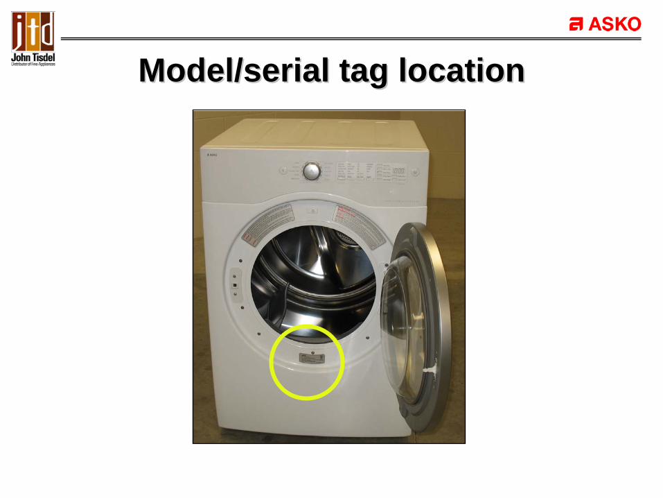
Model/serial tag locationModel/serial tag location
Electrical considerationsElectrical considerations
•• 240 VAC 240 VAC •• 30 AMP30 AMP•• 3 or 4 wire as designated by local code3 or 4 wire as designated by local code

Duct considerationsDuct considerations
•• Max length of 4Max length of 4”” diameter rigid metal duct diameter rigid metal duct –– 6565’’•• Max length of 4Max length of 4”” diameter flex metal duct diameter flex metal duct –– 4545’’
–– Deduct 6Deduct 6’’ for each elbowfor each elbow–– No more than four 90 degree elbows if possibleNo more than four 90 degree elbows if possible–– Do not use plastic or thin foil duct materialDo not use plastic or thin foil duct material
•• Use as few joints as possibleUse as few joints as possible•• Duct tape all jointsDuct tape all joints

Positioning of unitPositioning of unit
•• ½”½” clearance at the sides and top of unitclearance at the sides and top of unit•• Minimum of 6Minimum of 6”” clearance behind dryerclearance behind dryer•• Unit should be placed on a solid floorUnit should be placed on a solid floor•• Unit must be levelUnit must be level
–– Can effect tumbling action and humidity sensor Can effect tumbling action and humidity sensor accuracyaccuracy
–– Legs must be locked into placeLegs must be locked into place

Door swing can be reversedDoor swing can be reversed
Left hinge door swing Right hinge door swingLeft hinge door swing Right hinge door swing

Door reversal stepsDoor reversal steps
•• Remove bolts holding the door hinge to cabinetRemove bolts holding the door hinge to cabinet•• Remove the doorRemove the door•• Move the latch to the opposite side of openingMove the latch to the opposite side of opening•• Turn door upsideTurn door upside--down and reinstall on down and reinstall on
opposite sideopposite side•• Reinstall bolts holding door hinge to cabinetReinstall bolts holding door hinge to cabinet

General InformationGeneral Information
•• WarrantyWarranty•• Model/serial locationModel/serial location•• Electrical considerationsElectrical considerations•• Duct considerationsDuct considerations•• Positioning of the unitPositioning of the unit•• Door swingDoor swing
ANY QUESTIONS ???ANY QUESTIONS ???

Dryer operationDryer operation
•• Sensor DrySensor Dry•• Manual DryManual Dry•• Dry OptionsDry Options•• Temperature OptionsTemperature Options•• Dry time OptionsDry time Options•• Signal ToneSignal Tone•• Rack DryRack Dry
•• More TimeMore Time•• Less TimeLess Time•• Damp SignalDamp Signal•• Anti CreaseAnti Crease•• Delay StartDelay Start•• Child LockChild Lock

Control console Control console -- Dryer operationDryer operation
•• Sensor dry programsSensor dry programs–– Bulky Items Bulky Items -- temp high only; dryness adjustabletemp high only; dryness adjustable–– Towels Towels –– temp high only; dryness adjustabletemp high only; dryness adjustable–– Everyday Wear Everyday Wear –– temp midtemp mid--high; dryness high; dryness
adjustableadjustable–– Synthetics Synthetics –– temp medium; dryness adjustabletemp medium; dryness adjustable–– Gentle Gentle –– temp low; dryness adjustabletemp low; dryness adjustable–– Ultra Gentle Ultra Gentle –– temp low; dryness adjustabletemp low; dryness adjustable–– Iron Dry Iron Dry –– temp ultra low; dryness not adjustabletemp ultra low; dryness not adjustable

Control console Control console -- Dryer operationDryer operation
•• Manual dry programsManual dry programs–– Quick dry Quick dry –– temperature high;temperature high;–– Freshen Freshen –– temperature midtemperature mid--high;high;–– Air dry Air dry –– temperature temperature –– no heat no heat
Dry optionsDry options
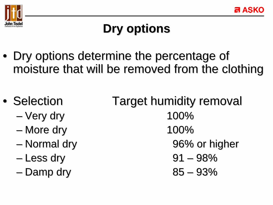
•• Dry options determine the percentage of Dry options determine the percentage of moisture that will be removed from the clothingmoisture that will be removed from the clothing
•• SelectionSelection Target humidity removalTarget humidity removal–– Very dryVery dry 100%100%–– More dryMore dry 100%100%–– Normal dryNormal dry 96% or higher96% or higher–– Less dryLess dry 91 91 –– 98%98%–– Damp dryDamp dry 85 85 –– 93%93%

Temperature options Temperature options (Only available on Manual Dry)(Only available on Manual Dry)
•• LevelLevel Heater on Heater offHeater on Heater off–– HighHigh 132F132F 145F145F–– Mid HighMid High 125F125F 138F138F–– MediumMedium 113F113F 125F125F–– LowLow 105F105F 118F118F–– Ultra LowUltra Low 91F91F 104F104F
Dry Time options (manual dry only)Dry Time options (manual dry only)
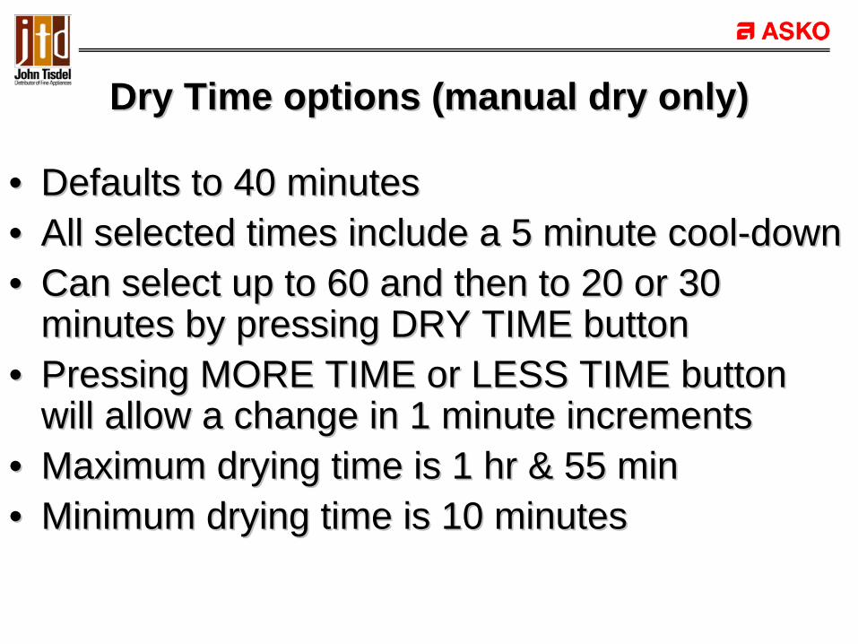
•• Defaults to 40 minutesDefaults to 40 minutes•• All selected times include a 5 minute coolAll selected times include a 5 minute cool--downdown•• Can select up to 60 and then to 20 or 30 Can select up to 60 and then to 20 or 30
minutes by pressing DRY TIME buttonminutes by pressing DRY TIME button•• Pressing MORE TIME or LESS TIME button Pressing MORE TIME or LESS TIME button
will allow a change in 1 minute incrementswill allow a change in 1 minute increments•• Maximum drying time is 1 hr & 55 minMaximum drying time is 1 hr & 55 min•• Minimum drying time is 10 minutesMinimum drying time is 10 minutes

Signal tone optionsSignal tone options
•• Selection from Low to HighSelection from Low to High•• Selection cannot be changed during the Selection cannot be changed during the
program operationprogram operation

Rack DryRack Dry
•• Time defaults to 55 minutesTime defaults to 55 minutes•• Only Low or Ultra Low heat can be selectedOnly Low or Ultra Low heat can be selected•• Time can be adjusted with More/Less buttonTime can be adjusted with More/Less button•• AntiAnti--crease or Damp Signal cannot be selectedcrease or Damp Signal cannot be selected

More Time optionMore Time option
•• This button increases the selected time in one This button increases the selected time in one minute incrementsminute increments
•• Time increases up to 155 minutesTime increases up to 155 minutes•• This option can be used with Manual dry and This option can be used with Manual dry and
Anti Crease optionsAnti Crease options

Less Time optionLess Time option
•• This button decreases the selected time in one This button decreases the selected time in one minute incrementsminute increments
•• Time decreases up to 15 minutesTime decreases up to 15 minutes•• This option can be used with Manual dry and This option can be used with Manual dry and
Anti Crease optionsAnti Crease options

Damp signalDamp signal
•• Only operational in Sensor Dry selectionOnly operational in Sensor Dry selection•• Dryer will beep every 3 seconds after target Dryer will beep every 3 seconds after target
humidity has been achievedhumidity has been achieved•• The beep stops if the door is opened or the The beep stops if the door is opened or the
Start/Stop button is pressedStart/Stop button is pressed

Anti CreaseAnti Crease
•• This selection does not change the program timeThis selection does not change the program time•• At end of cycle motor runs for 10 seconds out of each At end of cycle motor runs for 10 seconds out of each
6 minutes6 minutes–– The motor runs for 10 seconds, stops for 5 minutes and 50 The motor runs for 10 seconds, stops for 5 minutes and 50
seconds.seconds.
•• To stop Anti Crease function, press Start/Stop OR the To stop Anti Crease function, press Start/Stop OR the Power buttonPower button
•• This function can be selected or cancelled during the This function can be selected or cancelled during the programprogram

Delay startDelay start
•• The preThe pre--set time indicates the delay timeset time indicates the delay time•• Pressing the Delay Start button displays the Pressing the Delay Start button displays the
delay time in the displaydelay time in the display•• To preTo pre--set operationset operation
–– Select cycleSelect cycle–– Select Delay StartSelect Delay Start–– Select delay timeSelect delay time–– Press Start/Stop buttonPress Start/Stop button
Child LockChild Lock
•• After program begins, press and hold the Child After program begins, press and hold the Child Lock button for 3 secondsLock button for 3 seconds
•• All functions with exception of Power button are All functions with exception of Power button are locked outlocked out
•• To clear Child Lock, press and hold Child Lock To clear Child Lock, press and hold Child Lock button for three seconds OR press the Power button for three seconds OR press the Power buttonbutton

Dryer operationDryer operation
•• Sensor DrySensor Dry•• Manual DryManual Dry•• Dry OptionsDry Options•• Temperature OptionsTemperature Options•• Dry time OptionsDry time Options•• Signal ToneSignal Tone•• Rack DryRack Dry
•• More TimeMore Time•• Less TimeLess Time•• Damp SignalDamp Signal•• Anti CreaseAnti Crease•• Delay StartDelay Start•• Child LockChild Lock
ANY QUESTIONS ???ANY QUESTIONS ???

TearTear--down proceduredown procedure
•• Product disassemblyProduct disassembly•• Component functionComponent function•• Circuit flow for various componentsCircuit flow for various components

Front console removalFront console removal
Remove screw cover at left end of consoleRemove screw cover at left end of consoleRemove screw to release the consoleRemove screw to release the console

Front console removalFront console removal
Lift up on the console assembly to releaseLift up on the console assembly to releasePull forward to expose harness connectionsPull forward to expose harness connections
Disassembled control consoleDisassembled control console
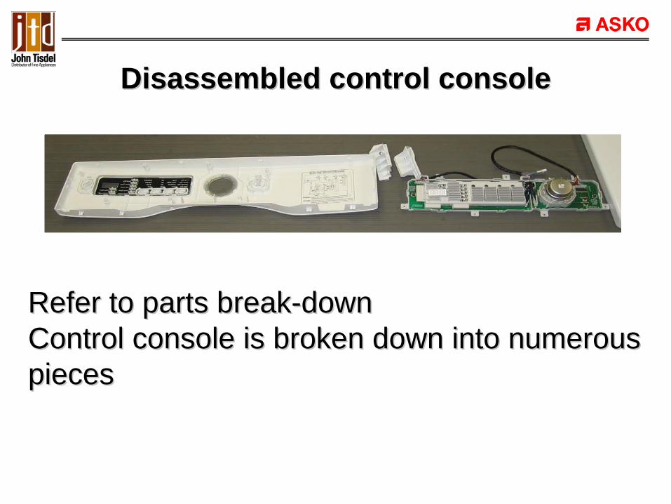
Refer to parts breakRefer to parts break--downdownControl console is broken down into numerousControl console is broken down into numerouspiecespieces
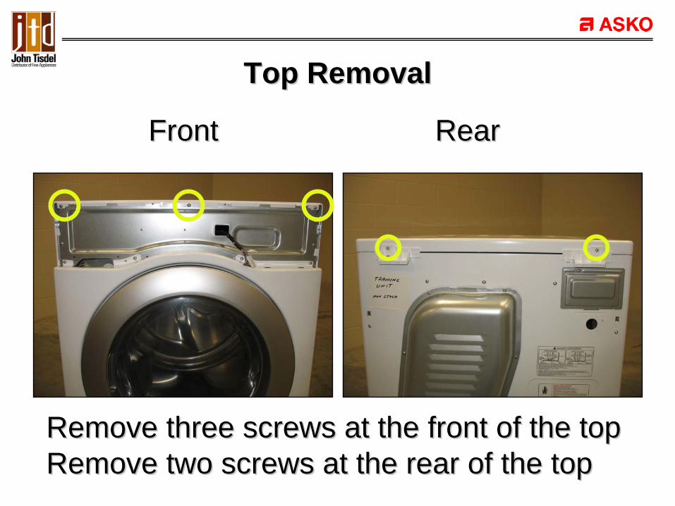
Top RemovalTop Removal
Remove three screws at the front of the topRemove three screws at the front of the topRemove two screws at the rear of the topRemove two screws at the rear of the top
Front RearFront Rear
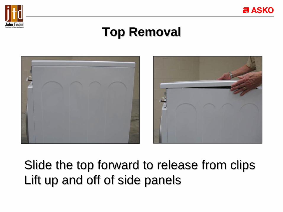
Top RemovalTop Removal
Slide the top forward to release from clipsSlide the top forward to release from clipsLift up and off of side panelsLift up and off of side panels

PCB PCB –– Power Control BoardPower Control Board
Located on side wall under main topLocated on side wall under main top

Test points at Control BoardTest points at Control Board
Input voltage at the power control boardInput voltage at the power control boardCon3 Con3 –– blue wireblue wireCon2 Con2 –– white wirewhite wire
Should measure 120VACShould measure 120VAC
Blue wireBlue wire
White wireWhite wire

Test points at Control BoardTest points at Control Board
Output voltage Output voltage –– 120VAC to motor120VAC to motorCon1Con1-- violet wireviolet wireCon2 Con2 –– white wirewhite wire
Should measure 120VACShould measure 120VAC
Violet wireViolet wire
White wireWhite wire
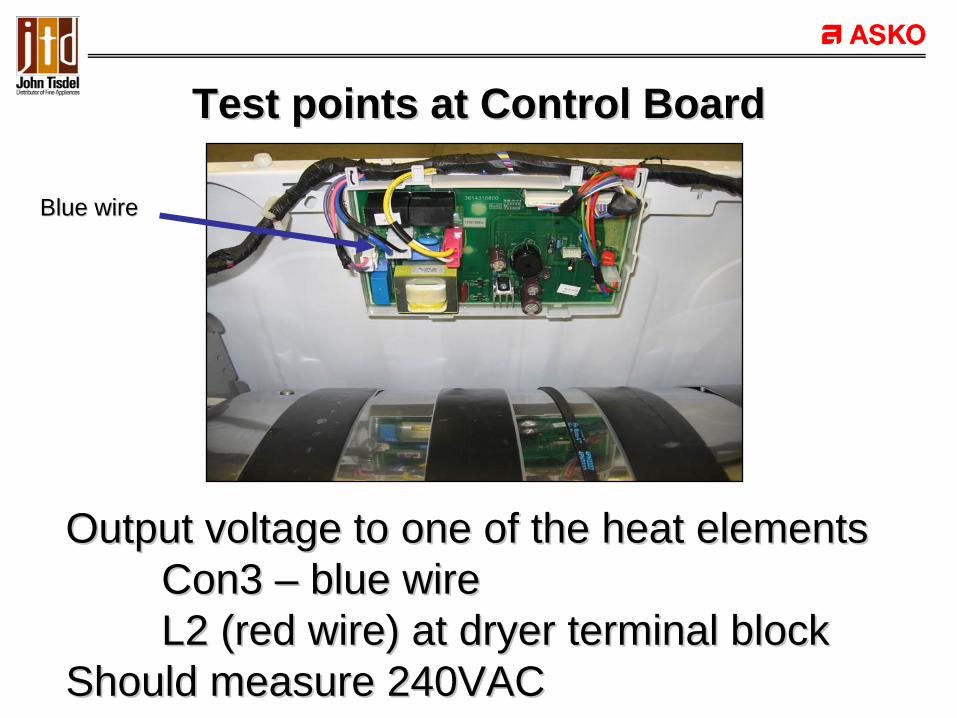
Test points at Control BoardTest points at Control Board
Output voltage to one of the heat elementsOutput voltage to one of the heat elementsCon3 Con3 –– blue wireblue wireL2 (red wire) at dryer terminal blockL2 (red wire) at dryer terminal block
Should measure 240VACShould measure 240VAC
Blue wireBlue wire
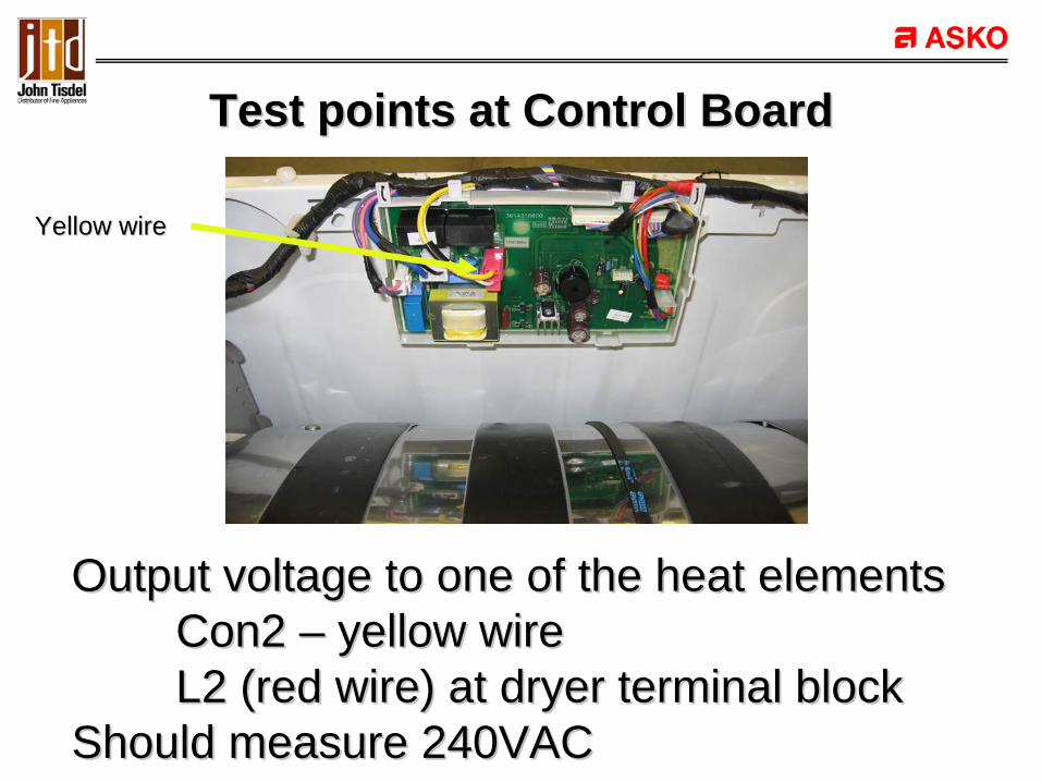
Test points at Control BoardTest points at Control Board
Output voltage to one of the heat elementsOutput voltage to one of the heat elementsCon2 Con2 –– yellow wireyellow wireL2 (red wire) at dryer terminal blockL2 (red wire) at dryer terminal block
Should measure 240VACShould measure 240VAC
Yellow wireYellow wire

Test points at Control BoardTest points at Control Board
Resistance check of the fan thermisterResistance check of the fan thermisterCon4 Con4 –– Orange wireOrange wireCon4 Con4 –– Blue wireBlue wire
Should measure 50K at room temperatureShould measure 50K at room temperature
Orange wireOrange wire
Blue wireBlue wire

Test points at Control BoardTest points at Control Board
Resistance check of the moisture sensorResistance check of the moisture sensorCon4 Con4 –– red wirered wireCon4 Con4 –– green wiregreen wire
Should read open with no moistureShould read open with no moistureThe more moisture the lower the resistanceThe more moisture the lower the resistance
Red wireRed wire
Green wireGreen wire

Front panel removalFront panel removal
Remove four screws at top of the panelRemove four screws at top of the panelRemove the three screws that fasten to filter Remove the three screws that fasten to filter housinghousingLift front panel up and offLift front panel up and off

Drum light receptacleDrum light receptacle
View with console removed View with front bulkhead removedView with console removed View with front bulkhead removed
15W bulb; 125VAC15W bulb; 125VAC

L1NL2
Light circuitLight circuit
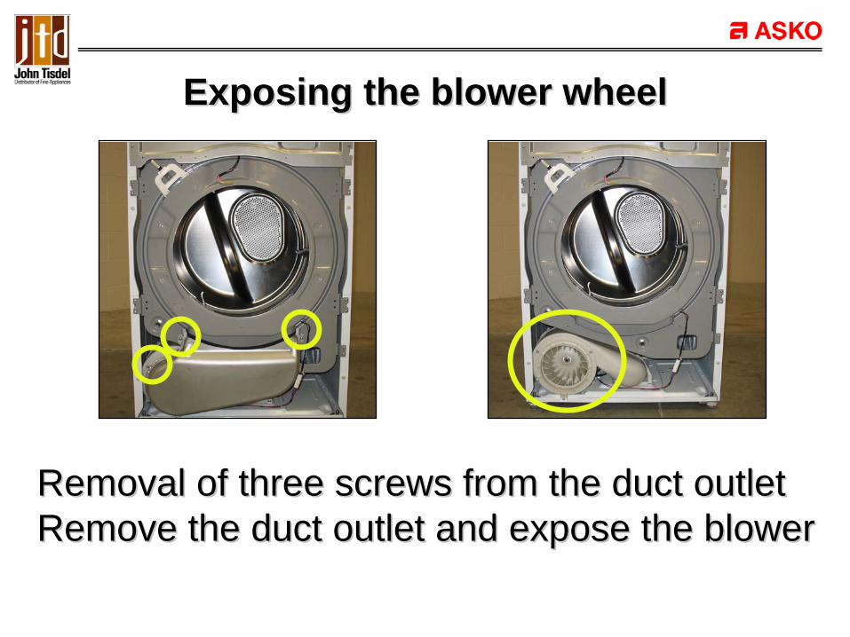
Exposing the blower wheelExposing the blower wheel
Removal of three screws from the duct outletRemoval of three screws from the duct outletRemove the duct outlet and expose the blowerRemove the duct outlet and expose the blower

Blower wheel removalBlower wheel removal
Remove two screws and the cover ringRemove two screws and the cover ringRemove the nut from center of blower wheelRemove the nut from center of blower wheelNut fastened with a reverse threadNut fastened with a reverse thread

Bulkhead removal from dryerBulkhead removal from dryer
Remove four screws from left side of bulkheadRemove four screws from left side of bulkheadRemove six screws from right side of bulkheadRemove six screws from right side of bulkheadDisconnect sensor wire connector & lift offDisconnect sensor wire connector & lift off

Drum removalDrum removal
Disconnect belt from tension pulleyDisconnect belt from tension pulleyRemove six screws from console bracketRemove six screws from console bracketRemove console bracket & lift drum outRemove console bracket & lift drum out
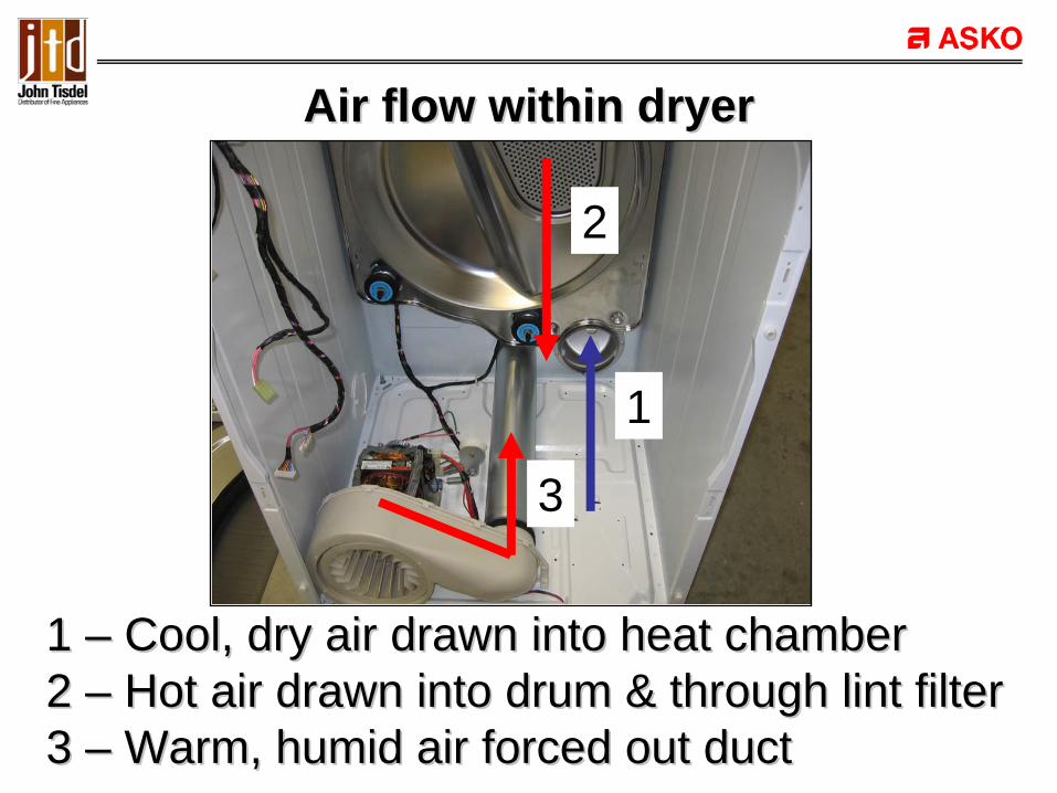
Air flow within dryerAir flow within dryer
1 1 –– Cool, dry air drawn into heat chamberCool, dry air drawn into heat chamber2 2 –– Hot air drawn into drum & through lint filterHot air drawn into drum & through lint filter3 3 –– Warm, humid air forced out ductWarm, humid air forced out duct
1
2
3
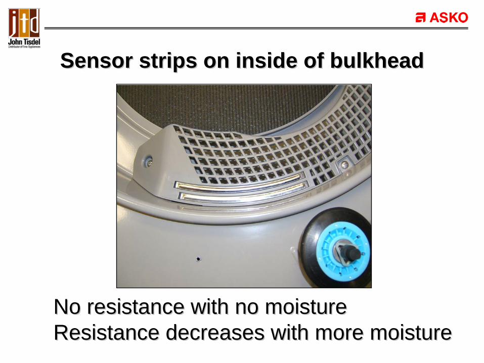
Sensor strips on inside of bulkheadSensor strips on inside of bulkhead
No resistance with no moistureNo resistance with no moistureResistance decreases with more moistureResistance decreases with more moisture

Sensor strips removed from bulkheadSensor strips removed from bulkhead
Sensor strips held in place with locking clipsSensor strips held in place with locking clips
L1NL2
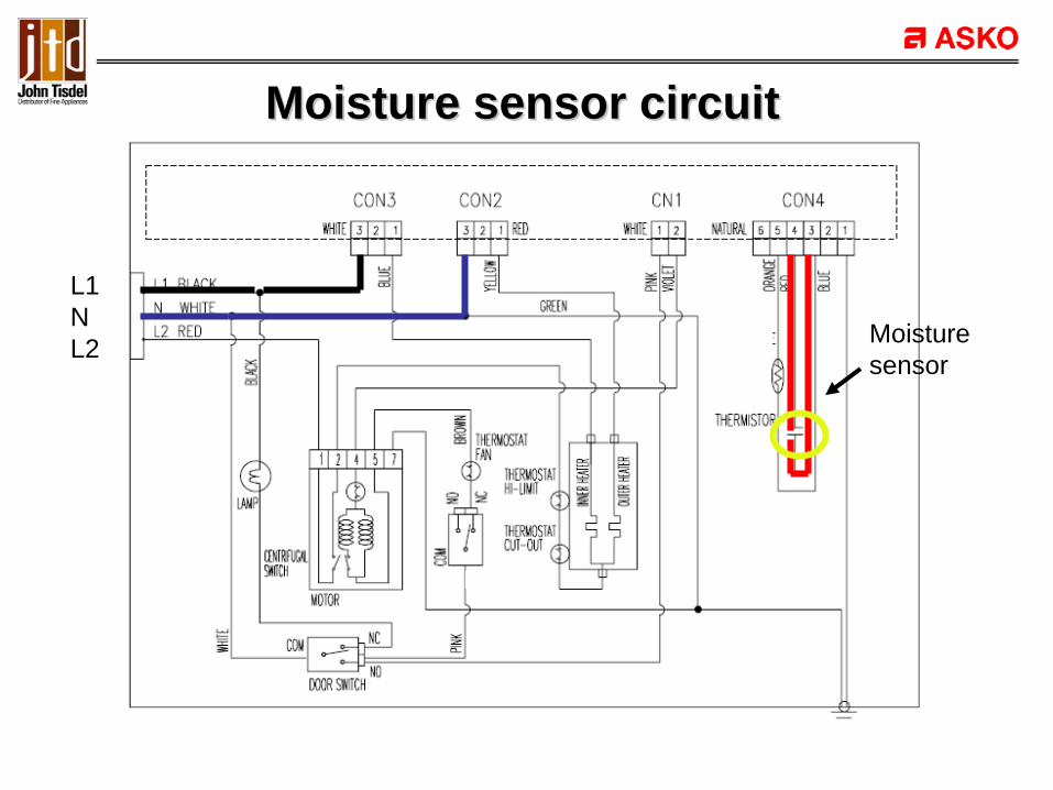
Moisture sensor circuitMoisture sensor circuit
Moisturesensor

Motor setting in cradleMotor setting in cradle
Clamp on each end hold motor in position on Clamp on each end hold motor in position on cradlecradle

Motor removed from the cradleMotor removed from the cradle
Front cradle has notch at bottom for properFront cradle has notch at bottom for properpositioning of motorpositioning of motor

Dryer motorDryer motor
Motor shaft has left hand thread for blower wheelMotor shaft has left hand thread for blower wheel120VAC; 5.9AMP120VAC; 5.9AMP1.6 OHM Resistance between contacts 4 & 51.6 OHM Resistance between contacts 4 & 5

Dryer motorDryer motor
1534
62
Contacts 1 to 2 Contacts 1 to 2 –– Heater circuitHeater circuitContacts 4 to 5 Contacts 4 to 5 –– Motor circuit Motor circuit

L1L1NNL2L2
Motor circuitMotor circuit
Motor
Contacts 1 to 2 Contacts 1 to 2 –– 240VAC; 25 AMP240VAC; 25 AMP
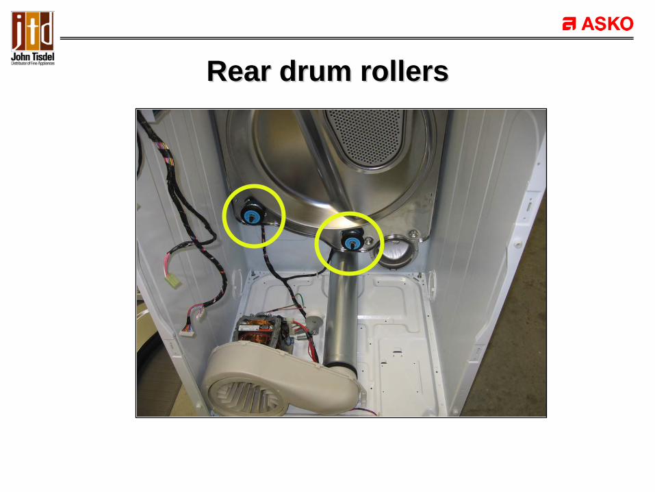
Rear drum rollersRear drum rollers
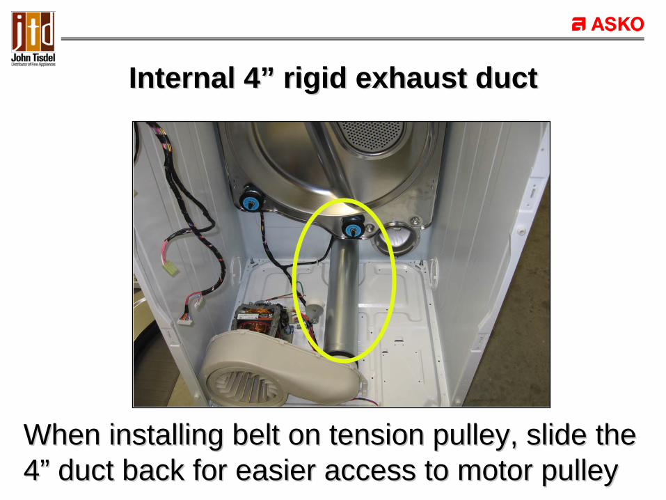
Internal 4Internal 4”” rigid exhaust ductrigid exhaust duct
When installing belt on tension pulley, slide theWhen installing belt on tension pulley, slide the44”” duct back for easier access to motor pulleyduct back for easier access to motor pulley

Fan thermostat and thermisterFan thermostat and thermister
Located on back side of duct housing adjacentLocated on back side of duct housing adjacentto motorto motor

Fan thermostatFan thermostat
Opens motor circuit at 185 degrees FOpens motor circuit at 185 degrees FCloses again when temperatures drop to 167 Closes again when temperatures drop to 167 degrees Fdegrees F

L1L1NNL2L2
FanT-stat
Fan Thermostat circuitFan Thermostat circuit

Cycles the heater to maintain temperatureCycles the heater to maintain temperature50 50 –– 52K OHM resistance @ room temperature52K OHM resistance @ room temperature
ThermisterThermister

Thermister checkThermister check
•• Place into cold water (50 Place into cold water (50 –– 68 degrees F)68 degrees F)–– 40,000 OHMS in 30 seconds40,000 OHMS in 30 seconds
•• Place into hot water (203 Place into hot water (203 –– 212 degrees F)212 degrees F)–– 4,000 OHMS in 30 seconds4,000 OHMS in 30 seconds
L1L1NNL2L2
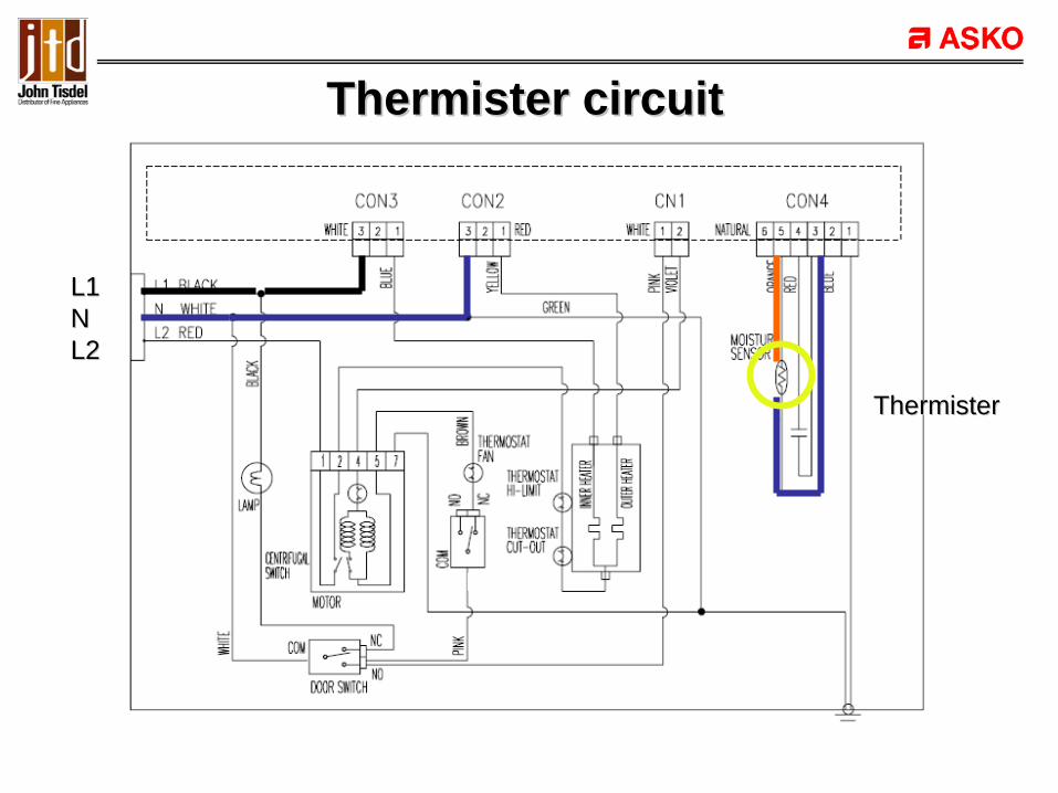
Thermister circuitThermister circuit
ThermisterThermister

Belt switchBelt switch
Mounted to motor support bracket Mounted to motor support bracket

Belt switchBelt switch
Contacts C to N/C provide for motor circuitContacts C to N/C provide for motor circuitIf belt breaks the belt switch contacts open and If belt breaks the belt switch contacts open and the motor circuit opens and the motor stopsthe motor circuit opens and the motor stops

L1NL2
BeltSwitch
Belt Switch circuitBelt Switch circuit

Door switchDoor switch
Mounted on inside of font panelMounted on inside of font panel

L1L1NNL2L2
Door Switch circuitDoor Switch circuit
Door SwitchDoor Switch

Heat chamber Heat chamber –– rear of dryerrear of dryerCover on chamber Cover removedCover on chamber Cover removed
Fastened by twelve perimeter screwsFastened by twelve perimeter screwsTwo tabs at top prevent it from falling offTwo tabs at top prevent it from falling offPull housing out at bottom and lift offPull housing out at bottom and lift off

Heat elementHeat element
Heat chamber removed from dryer Heating element Heat chamber removed from dryer Heating element
Two 2500W elements in parallel circuit Two 2500W elements in parallel circuit One or both elements will be energized depending on One or both elements will be energized depending on program selectedprogram selected
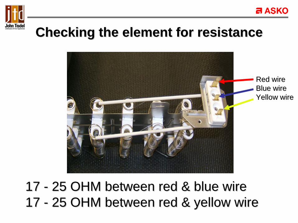
Checking the element for resistanceChecking the element for resistance
17 17 -- 25 OHM between red & blue wire25 OHM between red & blue wire17 17 -- 25 OHM between red & yellow wire25 OHM between red & yellow wire
Red wireRed wireBlue wireBlue wireYellow wireYellow wire

L1L1NNL2L2
CentrifugalCentrifugalswitchswitch
Heater circuit Heater circuit –– 240VAC240VAC
Motor must be running for heater to workMotor must be running for heater to work

High limit & cutHigh limit & cut--out (safety) thermostatsout (safety) thermostats
Located on the heater housingLocated on the heater housingHi limit is positioned above the cut Hi limit is positioned above the cut --outout
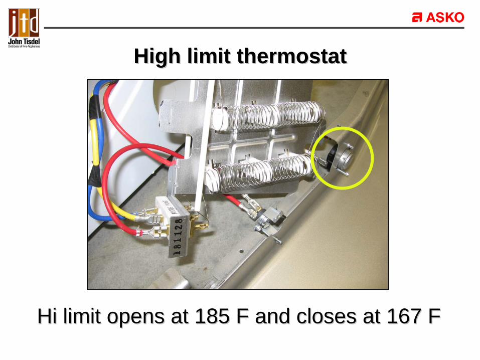
High limit thermostatHigh limit thermostat
Hi limit opens at 185 F and closes at 167 FHi limit opens at 185 F and closes at 167 F

CutCut--out (safety) thermostatout (safety) thermostat
Cut-out opens at 284 F and closes at -22 FIf it opens it should be replaced

L1L1NNL2L2
TT--stat:stat:Hi limitHi limitCutCut--outout
Heater thermostat circuitHeater thermostat circuit

Front drum rollerFront drum roller
Each roller is held on roller shaft with triangularEach roller is held on roller shaft with triangularplastic keeperplastic keeper

TearTear--down proceduredown procedure
•• Product disassemblyProduct disassembly•• Component functionComponent function•• Circuit flow for various componentsCircuit flow for various components
ANY QUESTIONS ???ANY QUESTIONS ???

Error CodesError Codes

Error CodesError Codes
•• H1 H1 –– Humidity sensor issueHumidity sensor issue•• H2 H2 –– Thermister error issueThermister error issue•• H5 H5 –– Heater issue (over heat)Heater issue (over heat)•• H4/H6 H4/H6 –– Heater disconnectHeater disconnect

H1 Error H1 Error –– Humidity sensorHumidity sensor
•• Indicates a short in the humidity sensor circuitIndicates a short in the humidity sensor circuit•• Measured values lower than 22 OHMSMeasured values lower than 22 OHMS•• The unit buzzes every 10 minutes for a period The unit buzzes every 10 minutes for a period
of 10 secondsof 10 seconds•• The error display goes off when the power is The error display goes off when the power is
switched offswitched off

H2 Error H2 Error –– ThermisterThermister
•• Shorted or open Thermister circuitShorted or open Thermister circuit•• The unit buzzes every 10 minutes for a period The unit buzzes every 10 minutes for a period
of 10 secondsof 10 seconds•• The error display goes off when the power is The error display goes off when the power is
switched offswitched off

H5 Error H5 Error –– Heater overheatHeater overheat
•• Temperature sensor indicates 185 Temperature sensor indicates 185 degrees F or higherdegrees F or higher

H4/H6 Error H4/H6 Error –– Heater errorHeater error
•• Consumer receives no indication of errorConsumer receives no indication of error•• Check error through following steps, with no Check error through following steps, with no
load in the dryerload in the dryer
•• Heater selfHeater self--testtest–– Push POWER button while holding in DAMP Push POWER button while holding in DAMP
SIGNAL & MORE TIME buttonsSIGNAL & MORE TIME buttons–– Both heaters will be energized & motor will runBoth heaters will be energized & motor will run

H4/H6 Error H4/H6 Error –– Heater error Heater error –– ContCont’’dd
•• The unit will run a check of the initial The unit will run a check of the initial temperature and then again after two minutes temperature and then again after two minutes of run timeof run time–– If the difference is 68F or greater, OK is displayed in If the difference is 68F or greater, OK is displayed in
the display windowthe display window–– If the temp difference is between 41F & 66F, then If the temp difference is between 41F & 66F, then
H6 is displayed indicating a loss of one of the H6 is displayed indicating a loss of one of the heatersheaters
–– If the temp difference is 41F or below, then an H4 is If the temp difference is 41F or below, then an H4 is displayed indicating a loss of both heater circuitsdisplayed indicating a loss of both heater circuits

Error CodesError Codes
Any questions ???Any questions ???

Diagnostic modeDiagnostic mode
TL751XXL Asko dryerTL751XXL Asko dryer

Component test proceduresComponent test procedures
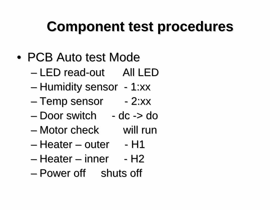
•• PCB Auto test ModePCB Auto test Mode•• Manual Test ModeManual Test Mode

PCB Auto test modePCB Auto test mode
•• Turn power on while pressing DRY Turn power on while pressing DRY SENSOR and TEMPERATURE buttonsSENSOR and TEMPERATURE buttons
•• Press DRY TIME buttonPress DRY TIME button•• Test mode will advance automaticallyTest mode will advance automatically
–– Must open /close door manually to test Must open /close door manually to test door switchdoor switch
Component test proceduresComponent test procedures
•• PCB Auto test ModePCB Auto test Mode–– LED readLED read--out All LEDout All LED–– Humidity sensor Humidity sensor -- 1:xx1:xx–– Temp sensor Temp sensor -- 2:xx 2:xx –– Door switch Door switch -- dc dc --> do> do–– Motor check will runMotor check will run–– Heater Heater –– outer outer -- H1H1–– Heater Heater –– inner inner -- H2H2–– Power offPower off shuts offshuts off
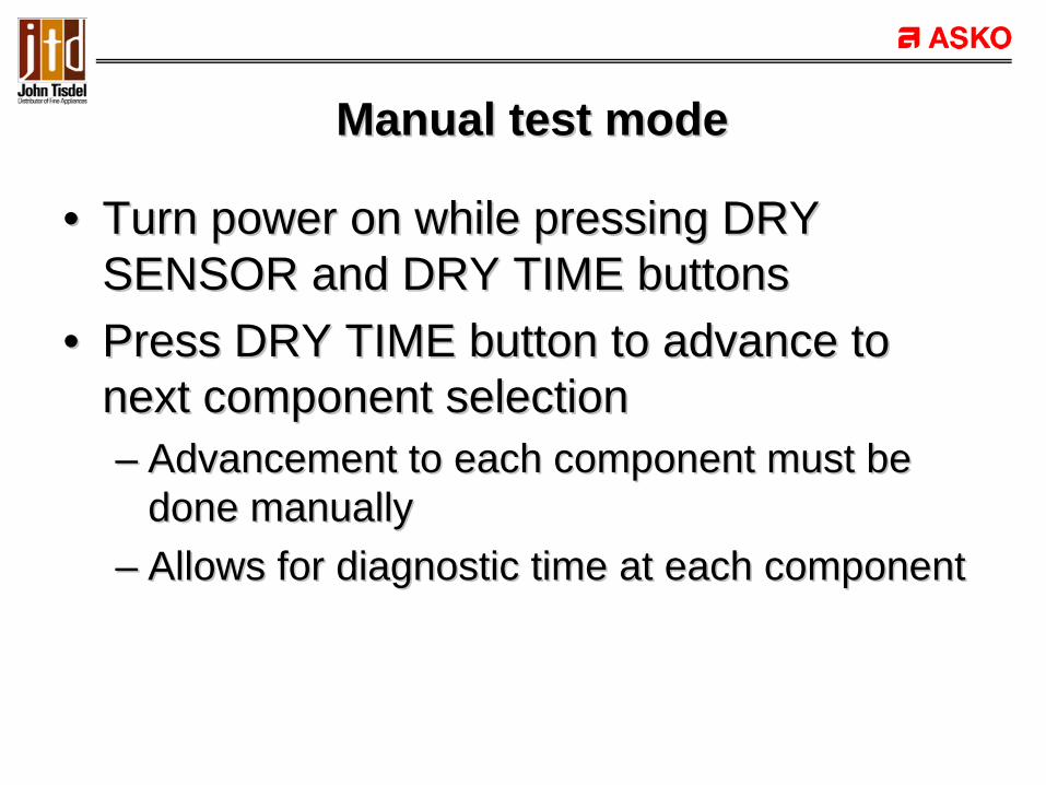
Manual test modeManual test mode
•• Turn power on while pressing DRY Turn power on while pressing DRY SENSOR and DRY TIME buttonsSENSOR and DRY TIME buttons
•• Press DRY TIME button to advance to Press DRY TIME button to advance to next component selectionnext component selection–– Advancement to each component must be Advancement to each component must be
done manuallydone manually–– Allows for diagnostic time at each componentAllows for diagnostic time at each component

Component test proceduresComponent test procedures
•• Manual test modeManual test mode–– Motor Motor -- 1:nr1:nr–– Heater 1 Heater 1 -- 2:H12:H1–– Heater 2 Heater 2 -- 3:H23:H2–– Heaters off Heaters off -- 4:nr4:nr–– Humidity sensor Humidity sensor -- 5:xx5:xx–– Temp sensor Temp sensor -- 6:xx 6:xx –– Door switch Door switch -- motor offmotor off–– Start/stop Start/stop -- motor onmotor on–– Power off Power off -- unit offunit off

Diagnostic modeDiagnostic mode
Any questions ???Any questions ???

HandsHands--on tearon tear--downdown

ThatThat’’s All Folkss All Folks