title the crystal structure analysis by the subsidiary
TRANSCRIPT

Title The Crystal Structure Analysis by the Subsidiary Maxma of theElectron Diffraction Pattern
Author(s) Uyeda, Natsu
Citation Bulletin of the Institute for Chemical Research, KyotoUniversity (1958), 35(5-6): 105-122
Issue Date 1958-03-30
URL http://hdl.handle.net/2433/75615
Right
Type Departmental Bulletin Paper
Textversion publisher
Kyoto University
The Crystal Structure Analysis by the Subsidiary
Maxma of the Electron Diffraction Pattern*
Natsu UYEDA**
(Suito Laboratory)
Received December 4, 1957
A nOw method for determining the crystal structure is presented, which is entirely „ based on the measuerment of linear components of the electron diffraction pattern
instead of the intensity of the diffraction as ordinary procedure used so far for struc- ture analysis in X-ray and electron diffraction methods.
The linear components of the diffraction pattern used here were those of the subsidiary maxima of diffraction spots. According to the dynamical theory of the electron diffraction, the displacement of the subsidinary maximum from the main dif- fraction spot gives the Fourier potential Vi,u of the periodic field of the crystal lattice,
which in turn gives some information about the structure factor of the crystal itself. A practical method for analysis of subsidiary diffraction spots to calculate the Fourier
potential was developed. A result of the application of this method to determine the unknown parameter of cadmiun bromide was also presented as an example of one
parameter case.
I. INTRODUCTION
In X-ray crystallography, almost all of the works so far made for deter- mining the parameter, the position of each atom in the unit cell, depended on
the analysis of the intensity of the diffracted X-ray beam by the crystal. When the electron diffraction method was used, the situation was the same. Though
such procedure depending on the intesity measurement are the most regular and
orthodox ones, the intensity measurement itself demands may techniques of high
grades and serious precausion. The principle of the method reported here, for determining the crystal parameter, depends only on the measurement of geometri-
cal quantities such as the linear distance and angular relationship of reflections described on the electron diffraction pattern and has a great advantage because the
precise rneasurment of such linear components is much easier than the intesity me surement.
The linear components of the diffraction pattern used here are those of the fine structure of diffraction spots accompanied by subsidiary maxima. The theo-
retical principle of this method is mainly basaed on the dynamical theory of elec- tron diffraction which was developed by Bethe", MacGillavey-', and Kato and
Uyeda". On the other hand, recent advance in the electron optics made it possible to
* Read at the Symposium for the Crystal Structure Analysis by the Electron Ditfrac- tion Method, held by the Physical Society of Japan, in Osaka on Nomenber 25th, 1956.
** I11 T;):
(105)
NATSU UYEDA
increase the resolving power of the electron diffraction pattern by the use of elec-
tron lenses in a diffraction unit and to describe such fine structures as subsidiary
maxima which appear in the elongated intensity regions of reciprocal lattice points
for thin lamellar crystals, split diffraction spots caused by the refraction effect of micro-crystals of various shapes, and so on. Recently, Cowely, Goodman and
Rees') also reported a similar method to draw a section of the pontential map of
the micro-crystal of magnesium oxide using the Fourier potentials calculated from
the linear component of the split spot groups of the electron difftaction pattern.
The small intervals of the subsidiary maxima also give some information
about the Fourier potential V,,,z of the periodic lattice structure of the crystal,
and, moreover, the V,,ke is closely related to the structure factor which give us
the final information about the lattice parameter itself.
The works relating to the analyis of subsidiary diffraction spots were made
by Hashimoto') with a molybdenum oxide crystal and by Uyeda et al.6 with the
crystal of molybdenum sulfide, both for the verification of the dynamical theory
itself, and the results proved the good coincidence between the theoretically and
experimentally obtained values of the Fourier potential for the crystal of a known
lattice structure. A. similar work was also reported by the author') on an applica-
tion to calculate the the thickness of the specially prepared lamellar crystals of
colloidal gold.
A report is hereby made on the results of the application of this method to
determine the position of the halogen atoms in the hexagonally close-packed layer
lattice with the lamellar micro-crystal of cadmium bromide, as an example of the
one parameter case.
II. THEORETICAL
According to the dymanical theory of electron diffraction, the interference
function along the normal direction to a principal habit surface of the crystal
is given, in place of the kinematical one, by a slightly modified form as.
sin27Mh _,,/(rhz)2.(1)
where M is the number of atomic lattice normal to the direction along which Eq. 1. is defined. The dynamical modification is made on the quantity hi, in the
form as
hr ^h2+(2d 2)
where h is the parameter in the reciplocal lattice along the direction nomal to the principal habit surface, and dv is the lattice spacing of the net plane normal
to the same direction. Furthermore, q is given by
2d,vV,a;,/2E - /cos01. cosf.,(3)
where V,,,c, ascribed to the spot of (hkl) reflection, is the Fourier potential of
the periodic field in the crystal, and 01 and Bs respectively correspond to the angles
contained between the normal to the crystal habit surface and the direction of
incident and diffracted eletron beam, whose wave length is equal to 2 under the
(106)
Crystal Structure Analysis by Subsidiary Diffraction Maxima
accelerating voltage E. In such a modified form, the periodic function expressed
in Eq. 1. has its maxima at the point where the parameter h,,, is given by
h°(2n+ 1l'(dN V,„,(4) 2M ) \2E-i/cos cos8J
where a is ordinal number for the subsidiary maxima and takes positive integer. When the crystal takes layered structure, whose lattice spacing dN, and has
a lamellar crystal habit, whose flat surface is parallel to the layer, thiskness D of the crystal is given by
D=M•d(5) When the crystal is thin and M is small, the interval as well as the height of
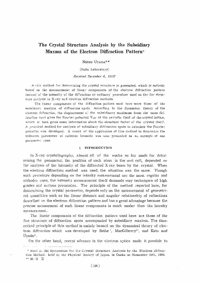
the subsidiary maxima become larger than those of the thicker crystal, as re-vealed by the Eq. 1; and this fact explains the elongation of the intensity region of the reciprocal lattice point in the direction normal to the habit surface. It is the advantage of the electron diffraction method, that, owing to the great interfering ability of the electron beam with the atoms, the sufficient intensity can be obtained for the diffracted beam even when the M, which is the number of the diffraction lattices, is small. This results in the complete seperation of the sub-sidiary maxima in the final diffraction pattern, coupled with the increase in the resolving power of the electron diffraction apparatus. These subsidiary maxima can be realized on the diffraction pattern by artificial rotation or fortuitous bending of the lamellar crystal as shown in Fig. 1, where the latter case is illustrated.
e,N P \
z
N,9Ny\. \\\
a.\` A
•N
19291 b eb~~ rEWALD SPURS Si
0------b--------- _I P (3S
0e'Vr- C0-----------------------------------s.t ••-----------
-I Fig. 1. Schematic illustration of the analysis of subsidiary maxima of elongateted
diffraction spots.
(107)

NATSU UYEDA
For the interpretation and the analysis of the election diffraction pattern, it is con-venient to consider the relationship between the reciprocal lattice and the Ewald sphere, as the intersection of the two reveals the diffraction pattern itself.. [a Fig. 1 (a), 0 and P are respectively the origin and the reciprocal lattice point, whose index is (hkl) and to which the principal maximum of Eq. 1 is ascribed. The direction NN' is parallel to the normal of the flaky habit surface of the lamellar crystal, which is superimposed as a section at the origin. On the line NN', the smalI blank circles, ranking symmetricaIly cn both sides of the principal maximum correspond to the position of subsidiary maxima of the interference function, which is shown schematically by the curve in the space.
When the crystal is rotated or bent around an axis perpendicular to the plane containing the three points, 0, P and the dispersion point A, the resultant rotation of the whole reciprocal lattice around the same axis at the origin causes the subsidiary diffraction points to describe concentric circles, as shown by the arcs in the figure. When the Ewald sphere cuts throught the point 1lakl), the section of these circular loci appears as the subsidiary maxima of the diffraction spots of the "elongation". When the simplest case is dealt with, where the nor-mal NN' is also contained in the OPA plane, the relationship between the Intervals of the subsidiary diffraction spots and those of reciprocal lattice can be revealed. Let 4Hn be the angular displacement contained between the principal spot and each n-th subsidiary one, which appears on the outer side on the main spot in the diffraction pattern, then the relationship between 9H, and h,,, the displacement of the n-th subsidiary maxima from the main one in the NN' direction. is given by
( /sin'2Hl2dH„(AHI )2'sinH1) h,=dN1.\ d~dj(6)
where d is the interplanar spacing of the (hkl) plane, Hl is the angle between the normal of the crystal and the incident electron beam. The procedure of deriving this equation is obvious from Fig. 1 (b), because the following relation,mn easily be brought about; (b + /i)2. = x2 coss 01 + (b + x sin 01 )2 where b, 11 anb x repre-sent such quantities as 1/d, d0„/1, and h„/dv respectively, which are characteris-tic of the reciprocal lattice. In the above case, the series of subsididiary diffrac-tion spots rank on a line in the radius direction. But, in general, they often deviate from the same direction, because the rotation axis is not always perpen-dicular to the dOP plane when fortuitous warping of the crystal is expected instead of the artificial rotation. In such a case, a generalized form of Eq. 6 must be used, which can be represented as:
))sin2Hicos2(r+a) 240,,cosl- 4Hn2l sinHlcos(Y f-o)-1
Where y and a are the angles between the radius direction passing through the main point and ranking direction of the subsidiary diffraction spots and also the projection of the normal through the main point is taken on the Ewald sphere respectively. (See Fig. 6 in the Appendix.) When the rotation axis is contained in the Ewald sphere which is approximated by a plane in an ordinary manner, a becomes zero, and Eq. 7 can be reduced to the next form:
( 108 )
Crystal Structure Snalysis by Subsidiary Diffraction Maxima
h ~=dvr1sin26i.cos&'r+248 osr+40,a2'lz_sintii cosy~(8)d2Ad22I ~. The same result can be obtained by replacing d in Eq. 6 by d/cos y. In practice,
following equation is most useful which can be given by the replacement of 40„/2
with dr./(rd) where 4r,h is the lineae displacement of n-th subsidiary diffraction
spot from the main one whose radious is given by r:
d.,' (. ,,Jr,~~ dr,h21 ,', h„— ci.{sin- Bi cos2(r±a)-I-2-cosr -f (r)!—sin 6icos(r+-a)j (9) Furthermone, when subsidiary diffraction spots rank on the radius direction
through the main spot, Eq. 8 completely accords with Eq. 6, as in such a case r
vanishes. The procedure to derive Eq. 7 is shown in the Appendix,.
On the other hand, V,,,ka is related to the structure factor through the follow-
ing equation:
ed,ed'--~-Qrcig g) V. , =~rV•F,ah:a=V(Z-f)e (10)
where V is the volume of the unit cell. The structure factor F,,.h•a of the crystal
corresponds to the term under the summation which must be carried out all over
the unit cell. When the space group of the crystal is determined from the diffrac-tion data by taking the index of each reflection into consideration, then the
structure factor can be derived though it contains the unknown parameters,
which in turn can be solved by several V,,h,1 values through Eqs. 8-10.
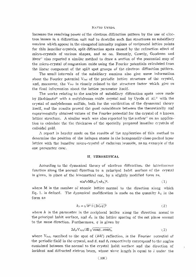
As an example of the one parameter case, the hexagonal crystal of RX,;
type whose space group is R3m was dealt with in the present work. The crystal
ab
---------- A
~~)l^~~hQlrw~l(~~~)r-----------B• 1641101WPA044VA 4,.A. ....„y......„,,,., y IF P y ltre/ y ',...4P%
tok r.:N. ei.i.s i.~ 4.ii4N---------m
Vytirtirey el ------- ra
0-- (-A BC 2.96p
It, 111,0 Bromine~1Y~1-~YIWO Y oz.6~ ~-~~'1Oa
X CadmiumX C
Fig. 2. The lattice structure and the stacking manner of atoms in cadmium bromide crystal.
(109)

NATSU UYEDA
of this type has a layered structure composed of hexagonally close-packed double sheets of halogen ions with the small metallic cations in the interstices of this
packing as shown in Fig. (2). The lateral stacking manner of neighbouring sheets becomes (AmB) (CmA) (BmC) (AmB)...., where A, B and C are the three possi-
ble positions of a hexagonally close-packed sheet in the lateral direction, as shown in Fig. 2 (b) and (c), and is well known as the rhombohedral stacking"'.
For cadmiun bromide, which has the above crystal structure, the unit cell constants are given to be a, = 3. 954 A, c, = 18.672 A, and V = 252. 8 A' in the hexa-
gonal description in place of the rhombohedral one for convenience of calculation. The atomic positions are given as follows") :
Cd : 000; 1/3, 2/3, 1/3; 2/3, 1/3, 2/3, Br : OOu; OOu; 1/3, 2/3, u+ 1/3; 1/3, 2/3, 1/3— u;
2/3, 1/3, u+2/3; 2/3, 1/3, 2/3—u,
where u is the unkown parameter and requires the precise determination in the
present work. Taking extinction law given for this stacking, h ± k — l = 3n, into account,
the structure factor F„a•a can be easily simplified with the data of atomic positions as follows:
Flo,/=3 (ZR—fi:) + 6 (Zx:—f_x) - cos 277ul,(11)
where Z and f are atomic number and the atomic scattering factor for X-ray res-
pectively and the suffixes R and X correspond to cadmium and bromine. Thus V,,k, is finally given as follow:
V„,., =0,054 d2,,k., [(Z—f)'ca+2(Z--f), cos 2rulJ, (12)
In prctice, the u value can be determined by the use of the V,,k1 curves for vari-ous hkl planes previously drawn against the parameter u and by taking the experi-mentally obtained V,,k, values on the curves.
III. EXPERIMENTAL
i) Apparatus
The electron diffraction unit used here is the three-stage electron microscope, SM-C3 which has the specimen holder for electron diffraction of high resolution work at the position between the intermediate and projector lenses. The image of the cross-over point of the electron source is reduced in size by objective lens and the intermediate lens projects it on the screen. Thus, the high resolution type electron diffraction pattern can easily be obtaind. The projector lens, when operated in coordination with the intermediate one, can project the magnified shadow image of the specimen on the screen in place of the diffraction
pattern of the same part. This can be used to detect the aspect of the crystal from which the diffraction pattern is originated. The intermediate diaphragm, whose aperture size can be continuously changed, was used to limit the area of the specimen as small as possible to avoid the confusion by the stray diffraction spots coming from unaimed crystals and any other disturbance of the subsidiary maxima from unexpected causes such as the simultaneous reflections within the
(110)

Crystal Structure Analysis by Subsidiary Diffraction Maxima
crystal itself. Close attention was also paid to avoid the specimen change
under the electron irradiation, as the sublimating point of cadmium bromide
is rather low. The exposure was therefore limited within a range from 30 seconds
to 2 minutes. By such precautions, no change can be observed either on the
diffraction pattern or in the electron image of the specimen at all.
ii) Specimen
The micro-crystal of cadmium bromide were prepared and mounted on the
specimen trager by the sublimation method in dried carbon dioxide to avoid
the effect of water and oxidation in recrystallization. The electron diffraction
pattern for each crystal proved that the micro-crystals are cadmium bromide of rhombohedral stacking. In this case, chemically prepared pure micro-crystals
of gold10 were used as the reference for the precise analysis of the spacings.
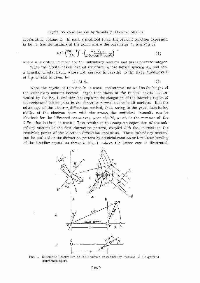
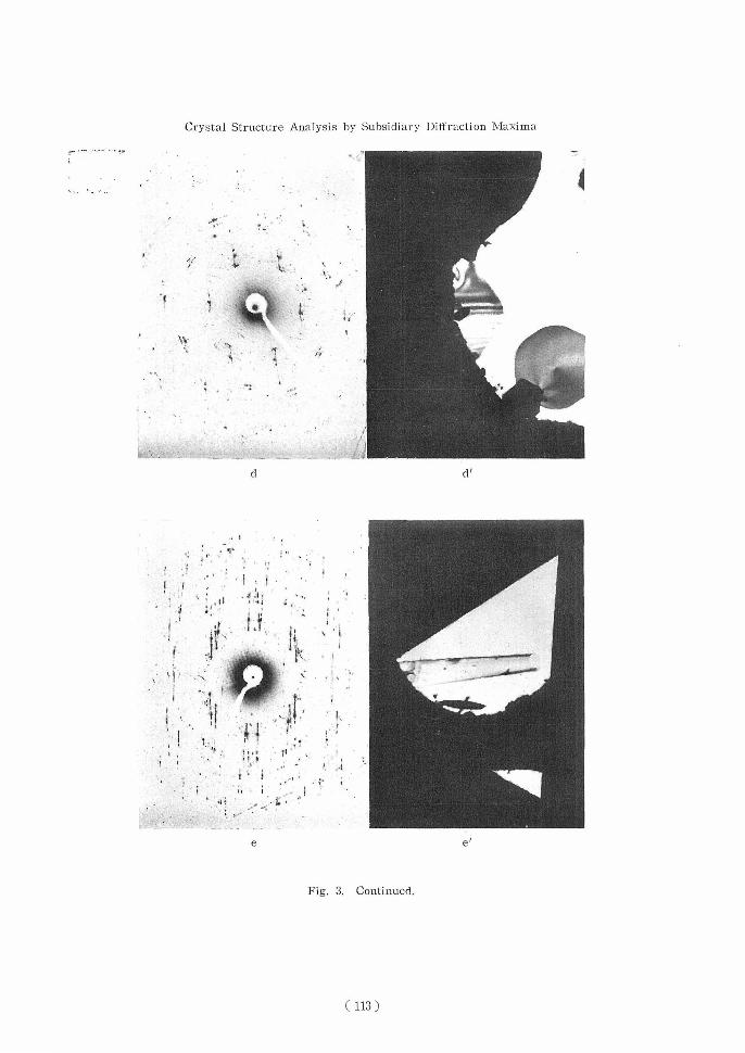
Some examples of the electron shadow images of the crystal are shown in
Fig. 3 together with the electron diffraction pattern corresponding to each crystal,
by which the identification was made. The azimuthal orientation of the two
pattern was corrected for each pair. The size of the crystal is distributed over a range from about 2 to 10 microns in the width of the hexagonal flat surface,
and the thickness is about a few hundred angstroms. The shape of the crystal
is nearly hexagonal with round apecies. Sometimes it rolled itself to a tube as
in Fig. 3 (e'). In such a case. the diffraction pattern becomes very complex
accompanied by the double diffraction and the simultaneous reflection. In another
case, not so extreme as in (e'), the crystals have more or less fortuitous warping
which can be proved, as Heidenreich1-1 pointed out, by the parallel extinction
fringes appearing on the habit surface, which were caused by the reflection of
r4
• 0
• * aa'
Fig. 3. The electron shadow micrographs of lamellar single micro-craystal of cadmium
bromide and their electron diffraction patterns.
(111)

NATSU UYEDA
+ w
f4y;,.
i ' '.y•
i
bb'
40
ri. 4" • #1,,:,
' f. .
Ii t K I
+
•
CC'
Fig. 3. Continued.
(112)
Crystal Structure Analysis by Subsidiary Diffraction Maxima
. * w
tti4
•
t~ M k
dd'
i
• + i ' ,
,fI,};
.,
t•
ti
•-14111111
ee{
Fig. 3. Continued.
( 113 )

Natsu UYEDA
09In 0 0 r~r~
*a4
•+r.. .
1,
ooin
00 •^rti
i •t
O Oo0 NN
s N
140004414'
i O r. htl'
O NNN
.. 1410. • . y . • -40.000.0OS• 40,0+ v d
N ,-,,--I,--,
*-4010101F-*** Na
AO
N .tia) ,,--a ,-1ti
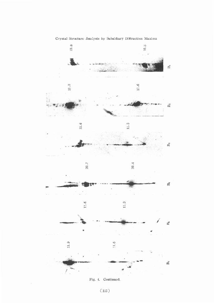
rIt
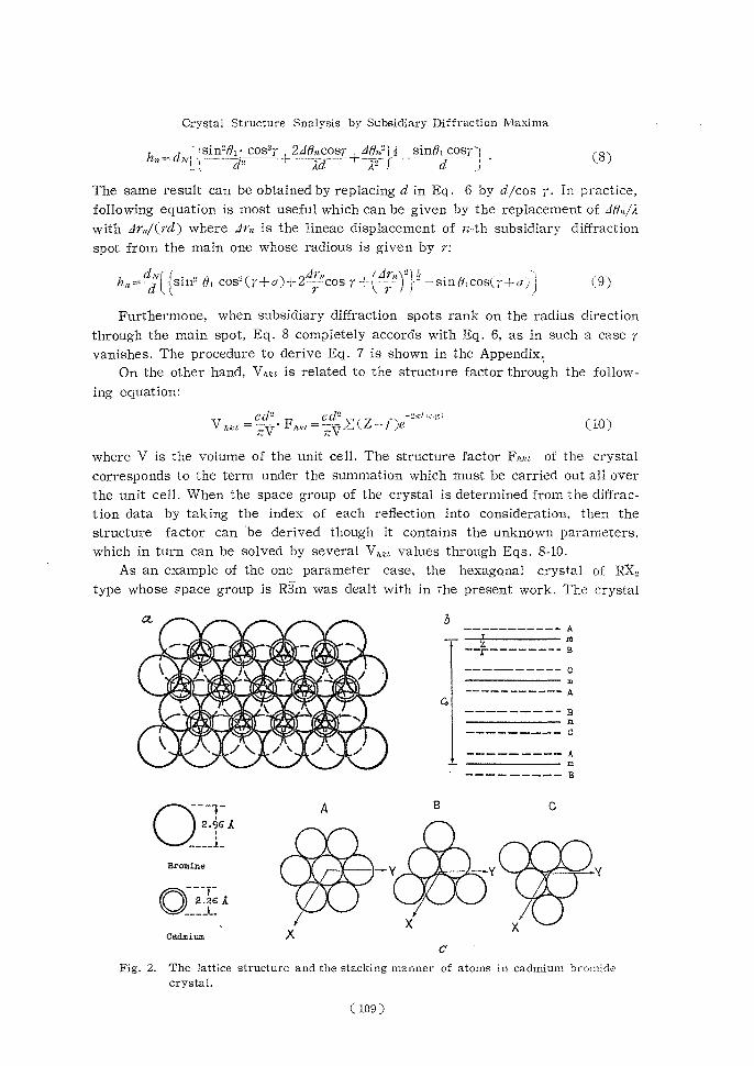
Fig. 4. Magnified photographs of elongated diffraction spots containing the subsidiary maxima.
(114)
Crystal Structure Analysis by Subsidiary Diffraction Maxima
co
•
00
_W
mco r-i
co
00 NN
flco
111011.*..4101101. PoPPIP Ppla 4' a m ~,w~"`Ca
a4
rn~ r;r;
Fig. 4. Continued.
(115)

Natsu UYEDA
CD 0
.0
CO
410. so.** .411111111.' .461114111010 40-
00
N ry6)
r-irl r1--I
„.a • ^ ^
• N
.' `. . mkt .Ca
electron at the part of the crystal where the inclination makes for suitable lattice
planes to fulfil the Bragg condition.
IV. RESULTS AND DISCUSSION
The electron diffraction pattern shown in Fig. 3 has the parallel elongations of diffracion spots in the direction normal to the extinction fringes of the corres-
ponding electron image of the crystal. The subsidiary maxima ranking in those elongations are distinctly detectable in the magnified photographs collected in Fig. 4. Effective camera length was also extended to about 8 to 10 meters. The
precise final magnification of the photographs was determined from the distance between the main diffraction spots. With those photographs, the displacement dr,Z of each subsidiary diffraction spots from the principal one was measured by
the distance between the centers of each spots and the angular displacement 4tz was calculated. The set of the hn values are calculated using the 4th values thus obtained through Eq. 6. The value of Oi was obtained by taking the orien-tation of the crystal to incident beam into account. The wave length A can be
(116)
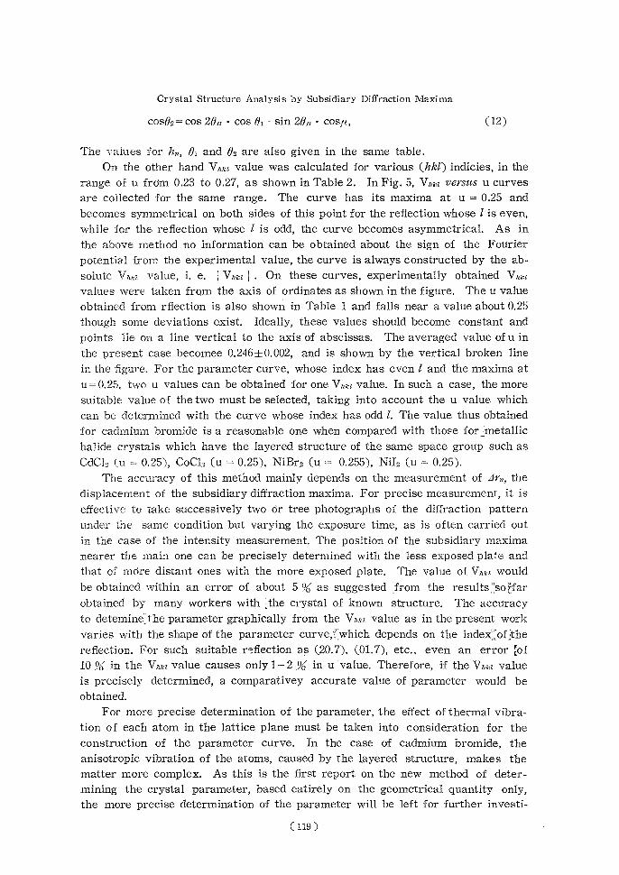
Crystal Structure Analysis by Subsidiary Diffraction Maxima
precisely determined with diffraction pattern itself using the accurate camera length of the apparatus.
On the other hand, as a linear relationship exists in Eq. 4 between 11,2 and
(n + 1/2 )2, the value of M can be estimated from the inclination of the line. M is generally an integer for a crystal, then the nearest integer value must be as-
signed to it, as the initial M obtained from the inclination is not always an integer.
With the value of M thus modified the h,, value can also be corrected through the
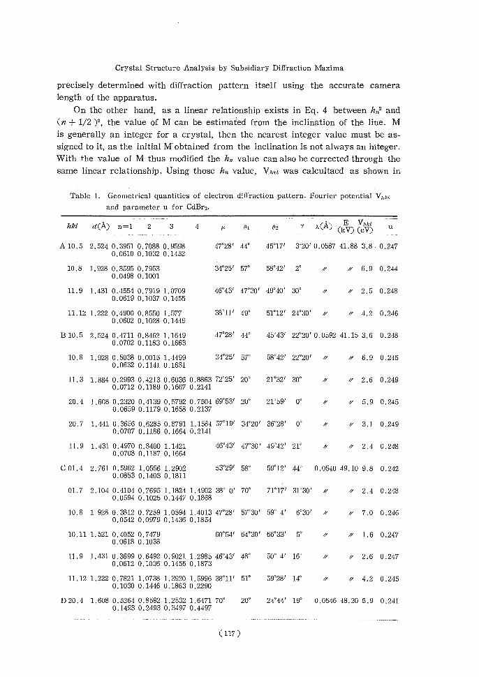
same linear relationship. Using those h,, value, Vida was calcultaed as shown in
Table 1. Geometrical quantities of electron diffraction pattern, Fourier potential Vnxa and parameter u for CdBr2.
------------
h'kl d(A) n=1 2 3 4 it Bi ez y A(A) C(iu (kV)(eV)
A 10.5 2.524 0.3951 0.7088 0.959847°28' 44° 45°17' 3°20'0.0587 41.88 3.8. 0.247 0.0610 0.1032 0.1452
10.8 1.928 0.3595 0.795334°25' 57° 58°42' 2° r' rr 6.9 0.244 0.0498 0.1001
11.9 1.431 0.4554 0.7919 1.070946°43' 47°30' 49°40' 30° // 1/ 2.5 0.248 0.0619 0.1037 0.1455
11.12 1.222 0.4900 0.8550 1.57738'11' 49° 51°12' 24°30' 1/ rr 4.2 0.246 0.0602 0.1028 0.1449
B 10.5 2.524 0.4711 0.8462 1.164947°28' 44° 45°43' 22°20' 0.0592 41.15 3.6 0.248 0.0702 0.1183 0.1663
10.8 1.928 0.5038 0.0015 1.449934°25' 57° 58°42' 22°20' // // 6.9 0.245 0.0632 0.1141 0.1631
11.3 1.884 0.2993 0.4213 0.6036 0.8863 72°25' 20° 21°32' 30° // rr 2.6 0.249 0.0712 0.1189 0.1667 0.2141
20.4 1.608 0.2320 0.4139 0.5792 0.7504 69°53' 20° 21°59' 0° d rr 5.9 0.245 0.0659 0.1179 0.1658 0.2137
20.7 1.441 0.3656 0.6285 0.8791 1.1584 57°19' 34°20' 36°28' 0° a // 3.1 0.249 0.0707 0.1186 0.1664 0.2141
11.9 1.431 0.4970 0.8400 1.142146°43' 47°30' 49'42' 21° 1/ // 2.4 0.248 0.0708 0.1187 0.1664
C 01.4 2.761 0.5962 1.0556 1.290253°29' 58° 59°12' 44° 0.0540 49.10 9.8 0.242 0.0853 0.1403 0.1811
01.7 2.104 0.4104 0.7695 1.1824 1.4902 38° 0' 70° 71°17' 31°30' rr a 2.4 0.248 0.0594 0.1025 0.1447 0.1868
10.8 1.928 0.3812 0.7259 1.0594 1.4013 47°28' 57°30' 59° 4' 6°30' 1/ rr 7.0 0.246 0.0542 0.0979 0.1436 0.1854
10.11 1.521 0.4052 0.747960°54' 64°30' 66°33' 5° // rr 1.6 0.247 0.0618 0.1038
11.9 1.431 0.3699 0.6492 0.9021 1.2985 46°43'48° 50° 4' 16° rr a 2.6 0.247 0.0612 0.1036 0.1455 0.1873
11.12 1.222 0.7821 1.0738 1.3920 1.5996 38°11'51° 59°28' 14° // '' 4.2 0.245 0.1030 0.1446 0.1863 0.2290
D20.4 1.608 0.5264 0.8592 1.2532 1.6471 70°20° 24°44' 19° 0.0546 48.20 5.9 0,241 0.1493 0.2493 0.3497 0.4497
(117)

Natsu UYEDA
Table 2. Calculated Vhk values for varying parmeter, expressed in unit of eV.
hkl d(A) u 0.230.24 0.52 0.26 0.27
01.4 2.7619.19.7 9.9 9.79.1
10.5 2.5246.65.0 3.3 1,60.0
01.7 2,104 -0.790.9 2.9 4,96.6
10.8 1.9285.06.6 7.1 6,65.0
11.3 1.8841.11.9 2.7 3.54,3
20.4 1.6085.55.8 6.0 5,85,5
10.11 1,521 -1.2 -0.1 2.1 4,35.4
20.7 1.441 -0.831.2 3.6 6.18.1
11,9 1.4315.03.8 2.0 0,3 -0.9
11,12 1.2221.93.6 4.4 3,61.9
oY 10---------------------------------------------------------------------- •
9 -'~.^Olu
8
II
6^sA,~LC tiOMArAllti
EFIII ,1 4 allillirA , Nippsw -.41.imm 5 oir^^^
A ,iiirmai
2
lid 4Mr MIMI_ 'WA~~^.
0.23 0.24 0.25 0.26 0.27 Parameter U.
Fig. 5. Fourier potenial versus parameter curves of CdBr2.
Table 1, again through Eq. 4, where E was determined using the wavelength
A and Oi is the same with the one used in Eq. 6. The value of 02 was estimated by taking the Bragg angle OR of the (hhl) reflection and the angle It between
the normals of the habit surface and the (hid) plane, through Eq. 12:
(118)
Crystal Structure Analysis by Subsidiary Diffraction Maxima
cos02= cos 20R • cos 01— sin 20„ • cos/2,(12)
The values for h,,, 01 and 02 are also given in the same table. On the other hand V,,kz value was calculated for various (hid) indicies, in the
range of u from 0.23 to 0.27, as shown in Table 2. In Fig. 5, V,,kz versus u curves are collected for the same range. The curve has its maxima at u = 0.25 and becomes symmetrical on both sides of this point for the reflection whose 1 is even,
while for the reflection whose 1 is odd, the curve becomes asymmetrical. As in the above method no information can be obtained about the sign of the Fourier
potential from the experimental value, the curve is always constructed by the ab-solute V,,k, value, i. e. V,,kl . On these curves, experimentally obtained V,,kz values were taken from the axis of ordinates as shown in the figure. The u value obtained from rflection is also shown in Table 1 and falls near a value about 0.25 though some deviations exist. Ideally, these values should become constant and
points lie on a line vertical to the axis of abscissas. The averaged value of u in the present case becomee 0.246±0.002, and is shown by the vertical broken line in the figure. For the parameter curve, whose index has even 1 and the maxima at u = 0.25, two u values can be obtained for one V,,ki value. In such a case, the more suitable value of the two must be selected, taking into account the u value which can be determined with the curve whose index has odd 1. The value thus obtained for cadmium bromide is a reasonable one when compared with those for metallic halide crystals which have the layered structure of the same space group such as CdCl (u = 0.25), CoCl2 (u = 0.25), NiBr2 (u 0.255), NiI2 (u = 0.25).
The accuracy of this method mainly depends on the measurement of dr, the displacement of the subsidiary diffraction maxima. For precise measurement, it is effective to take successively two or tree photographs of the diffraction pattern under the same condition but varying the exposure time, as is often carried out in the case of the intensity measurement. The position of the subsidiary maxima nearer the main one can be precisely determined with the less exposed plate and that of more distant ones with the more exposed plate. The value of V,,k,z would be obtained within an error of about 5 V as suggested from the resultsso Tfar
obtained by many workers with the crystal of known structure. The accuracy to detemine.the parameter graphically from the Vhkz value as in the present work
varies with the shape of the parameter curve,' which depends on the index„of :the reflection. For such suitable reflection as (20.7), (01.7), etc., even an error of 10 V in the V,ekl value causes only 1— 2 o in u value. Therefore, if the V,,kz value is precisely determined, a comparativey accurate value of parameter would be obtained. For more precise determination of the parameter, the effect of thermal vibra-tion of each atom in the lattice plane must be taken into consideration for the construction of the parameter curve. In the case of cadmium bromide, the anisotropic vibration of the atoms, caused by the layered structure, makes the matter more complex. As this is the first report on the new method of deter-mining the crystal parameter, based eatirely on the geometrical quantity only, the more precise determination of the parameter will be left for further investi-
(119 )

Natsu UYEDA
gations.
ACKNOWLEDGMENT
The author would like to express his sincere thanks to Dr. K. Tanaka, Kyto University, and Dr. H. Hashimoto, Kyoto Technical University for their
helpful advice and discussion, and also to Dr. R. Uyeda, Nagoya University, for
his useful suggestion, and to Dr. Cowly, Commonwealth Scientific and Industrial
Research Organization, Australia for his kind criticism. He would also like to express his sincere thanks to Dr. E. Suito, Kyoto University for his helpful encour-
agement.
REFERENCES
(1) H. A Bethe, Ann. Phys., 87. 55 (1928). (2) MacGillavry, Physica, 7, 333 (1940).
(3) N. Kato and R. Uyeda, Acta Cryst., 4, 229 (1951). (4) J. M. Cowley, P. Goodman and A. L. G. Rees, ibid., 10, 19 (1957).
(5) H. Hashimoto ; J.PIzys. Soc. Japan, 9, 150 (1954~. (6) R. Uyeda, T. Ichinokawa and Fukano, Acta Cryst., 7, 216 (1954).
(7) E. Suito and N. Uyeda, Proc. Japan Acad., 19, 331 (1953). (8) Z. Pinsker, "Electron Dffraction" Butterworth Sci. Publ., London (1953) p. 267.
(9) R. W. G. Wyckoff, "Crystal Structure," 1 (1951) IntersciencePubl., Inc., New York. (10) E. Suito and N. Uyeda, J. Etectronmicros., 1, 33 (1953). (11) R. Heidenreich, J. App. Phys., 20, 993 (1949).
APPENDIX
In the treatment described hereunder, the Ewald sphere is approximated by
a plane passing through the origin as in the ordinary electron diffraction. The
rotation axis of the reciprocal lattice caused by the bending of the crystal, in
.4 4
Electron beam
Bo •
N'4•.0 N
....,
E4L~rDLA PN S
H EWALD SPHERE
•
Fig. 6. Schematic illustration of the rotation of the reciprocal lattice for the arbitrarily
warping crystal.
( 120 )

Crystal Structure Analysis by Subsidiary Diffraction Maxima
general case, is not alway contained in the Ewald sphere and takes an arbitrary angle to the incident electron beam as shown in Fig. 6, where OC represents the
axis. AO is the direction of incident beam and stands normally to the, Ewald
sphere TI at the origin O. P and N represent the main diffraction maximum
(hkl) and position of the n-th subsidiary maximum on the normal direction along which Eq. 1 is defined in the relation to the parameter h. OP is equal to 1/(l (,=t).
The point A represents the dispersion point of the reciprocal lattice (Ausbreitungs-
punkt), then AP, which is equal to AO in length and has a quantity of 1/1„ coin-cides with the direction of the diffracted beam by (hkl) plane when P is contained
in the plane/1. Let BP is another normal to the same plane at P then / _A.PB=/i=20,;, where H,, is the Bragg angle for lzlzl reflection, and /BPN and ZAPN are equal
to N, and M; respectively. E is the foot of the normal NE which is put down to
the plane II, and PE becomes the projection of PN.
On the other hand, as the rotation of the reciprocal lattice is limited to the case
caused by the cylindrical warping of the original crystal, the axis of rotation
or warping is always contained in the habit surface of the crystal and perpendic-
ular to the normal which is parallel to PN in the reciprocal lattice, This is
also true even when the crystal takes a conical warping instead of the cyindrical
one, so far as only the neighbourhood of the narrow domain of the crystal,
where the (hkl) reflection in question actually takes place, is taken into account, as the type of the warping can be approximated by the cylindrical one for such a
narrow domain. Thus, one and only one plane S2.. can be defined which contains the nomal PN and cuts the rotation axis at right angle. The intersection is repre-
sented by C in the figure. In such a case, the locus of N is contained in the
plane Si at the rotation. The intersection of the two planes, II and I , becomes a line on which the subsidiary maxima of diffraction spots rank. S is the n-th
subsidiary diffraction maximum made by the rotation of N. Let OD be perpendi-
cular to SP, then CD also becomes normal to PD by the theorem of three per-
pendiculars. Let LOPD=1-, then PD=b•cosy. Furthermore, as OC1 NP, OH becomes normal to NP, where H is the foot of the perpendicular put down from C.
Then PH=b•cosp, wherep representsLOPH.
N •
kz C
• ,...,
5.~~E'I^LD snuaa D K -.--- aKH
Fig. 7. Schematic illustration of the analysis of subsidiary maxima in elongated
diffraction spots for an arbitrary rotation axis.
Now the geometrical relationship, which can be realized within the plane f2,
(121)

Natsu UYEDA
can be elucidated in the following simple relation, which can easily be found
among the geometrical quantities as shown in Fig. 7 :
CN2 = NK2 + (CP+ PK)2 = CS2 = (SP+PD )9+ CD2 = (SP+ PD )'-+ (CP2 - PD2 ),
These equation can be rewritten in the following form where b'=PD
z` x„2cos2H+(x,sine y)2=(an-}-b')2+hn2=(a,a+b')2+(y2-b')2
By simplificatiom, an equation relating to the unknown quantity xn can be obtained as follows :
xn2+2xny•sin 8-(a22+2an.b')=0.(11)
By solving the equation with respect to xn,
x„ = (y2sin26+2any +a22) - y • sin8,(14)
which can again be rewritten by the use of the essential value which is defined
in relation to the reciprocal lattice, such as
x„-h„/d,, y. sin8=co sit/ d, an= d0n/2,, b'=cosy/d ;(15)
When the angle r is put equal to (r+a), where a represents ZEPS, the following
relationship exists as :
NP -sin -cos8, r=EP-cos =NP •cos p,
and this proves the relationship as :
sin 8,. cos (y+a) =cos(16)
Therefore, Eq. 15 can be modified to the following form as :
1sin2 81 cos2(y+a)+248n cosy +40,2 0 sinficos(y+a)' (17) d2Ad22 1 d
Furthermore, by replacing 4B„/2 with Jr„/(rd), the following equation can be
derived from Eq. 15 as :
1z„=dN(cos-«+2-49:2cod {-~y"2-cos,uJ(18) Where the third term in the parenthesis may often be neglected as it becomes
a very small quantity. And in the case, where the rotation axis is containd in
the Ewald sphere, a vanishes, and Eq. 18 results:
n
hn=df sin2th cos2r+24n cosy +( rdr)1- sin 8i cosy)(19) This is the most convenient equation for practical calculation of hn value from
the diffraction data.
(122)