title: simulation of fatigue in composite components using ... · title: simulation of fatigue in...
TRANSCRIPT
Title: Simulation of fatigue in composite components using ANSYS nCodeDesignLife
Abstract: Rapid development of effective and robust components requires CAE simulation techniques capable of modelling performance and possible failure modes, including fatigue. Composite materials have many advantages for different classes of automotive components, but present additional challenges to the analyst due to the fact that parts manufactured from composite materials are in general inhomogeneous and anisotropic. This presentation describes how ANSYS nCode DesignLife may be used to model the durability of such composite components, particularly those made from short fibre reinforced injection moulded thermoplastics.
Simulation of Fatigue in Composite Components using ANSYS nCode DesignLife
Peter Heyes, HBM‐nCode
Summary
• Introduction – fatigue, DesignLife, composites• Fatigue analysis of composites: the challenges• Modelling process• Implementation in DesignLife• Further work
2012 Automotive Simulation World Congress 3
4
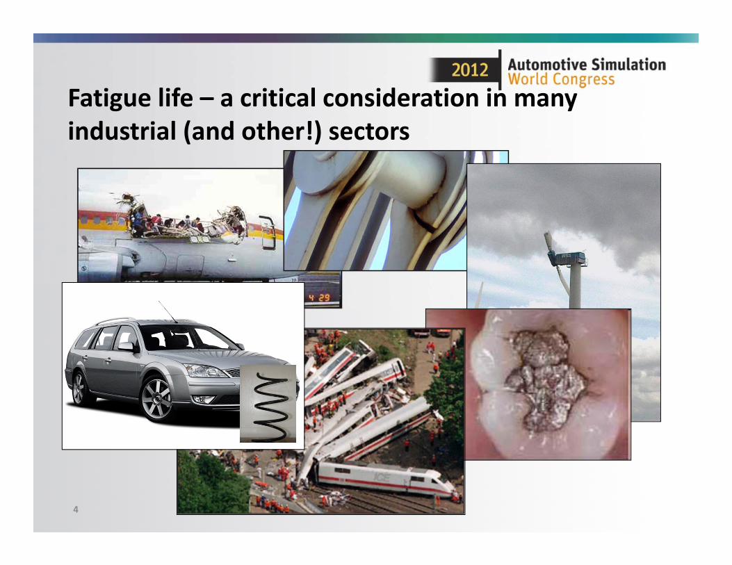
Fatigue life – a critical consideration in many industrial (and other!) sectors
5
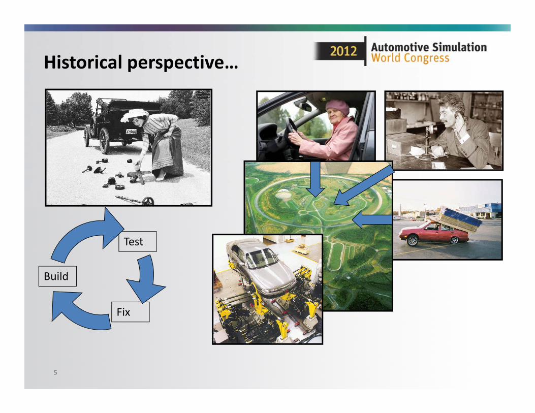
Historical perspective…
Build
Test
Fix
6
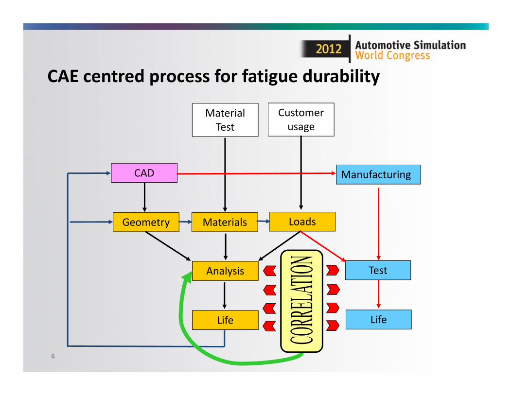
Geometry Materials Loads
Analysis
Life
CAD
Material Test
Customer usage
Manufacturing
Test
Life
CAE centred process for fatigue durability
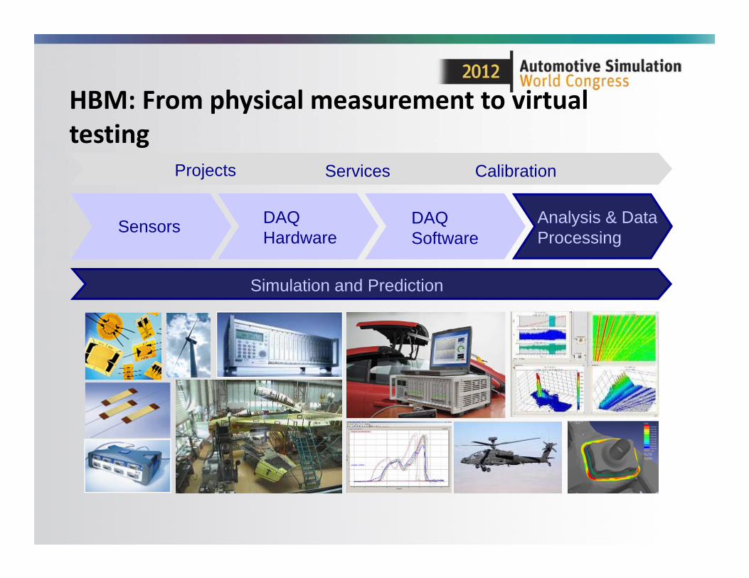
HBM: From physical measurement to virtual testing
Projects Services Calibration
DAQ Hardware
DAQ Software
SensorsSensors
Simulation and Prediction
Analysis & Data Processing
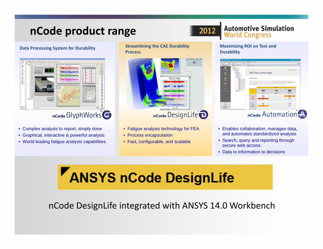
nCode product range
• Complex analysis to report, simply done• Graphical, interactive & powerful analysis• World leading fatigue analysis capabilities
• Enables collaboration, manages data, and automates standardized analysis
• Search, query and reporting through secure web access.
• Data to information to decisions
• Fatigue analysis technology for FEA• Process encapsulation• Fast, configurable, and scalable
Data Processing System for Durability Streamlining the CAE Durability Process
Maximizing ROI on Test and Durability
nCode DesignLife integrated with ANSYS 14.0 Workbench
9
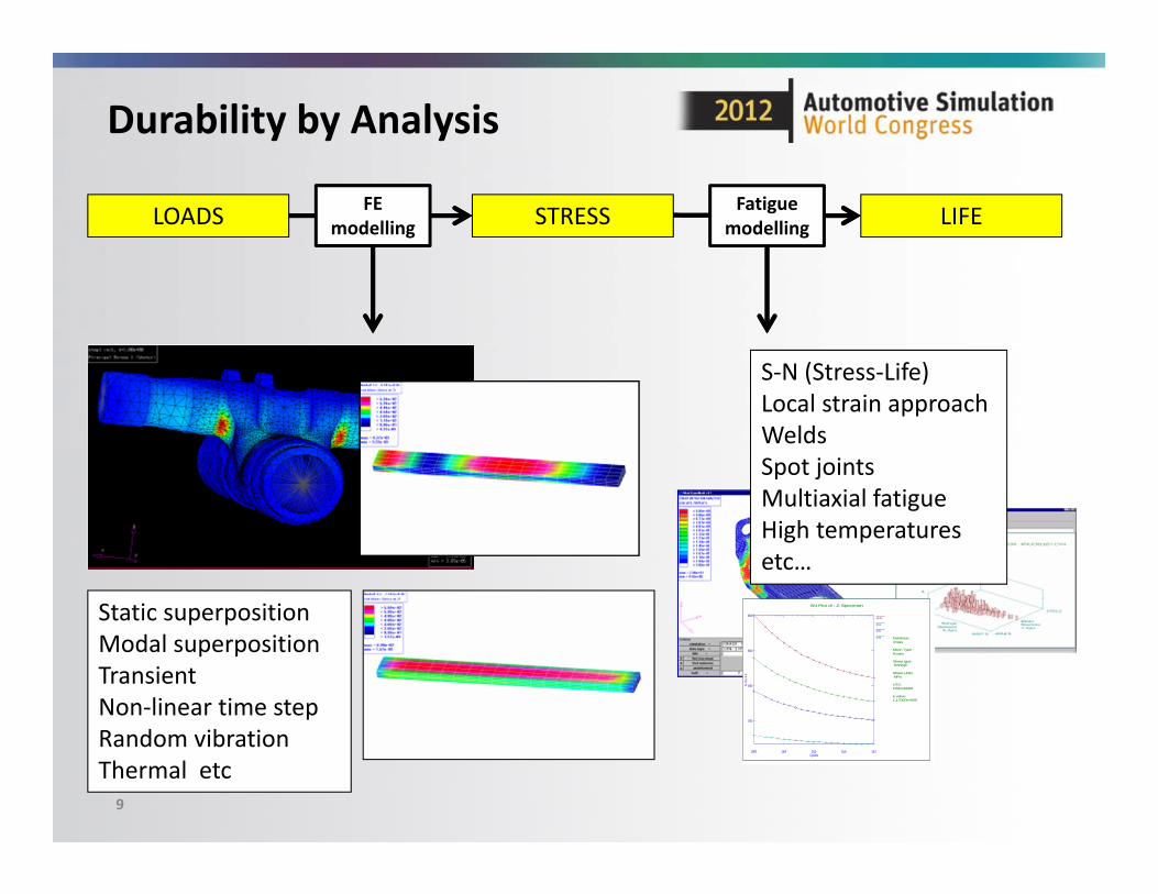
Durability by Analysis
Static superposition Modal superposition Transient Non‐linear time stepRandom vibrationThermal etc
SN Plot of : Z-Specimen
Database :nmats
Mean Type :R-ratio
Stress type: RANGE
Stress Units: MPa
UTS:1030.00000
E value:1.17000e+005
-0.5
0.1
0.5
0.9
Cycles
Str
es
s
1000 1E4 1E5 1E6 1E7
200
400
600
800
S‐N (Stress‐Life)Local strain approachWelds Spot jointsMultiaxial fatigueHigh temperaturesetc…
LOADS STRESS LIFEFE modelling
Fatigue modelling
10
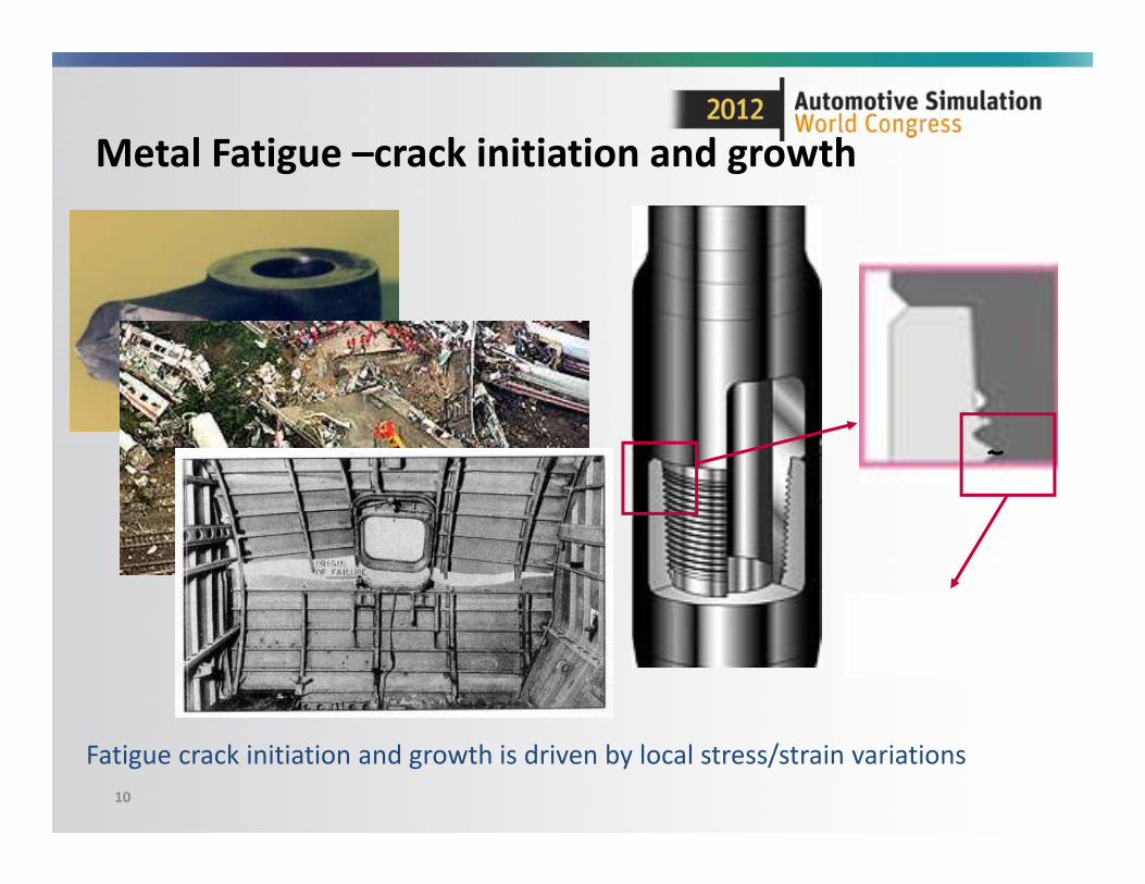
Metal Fatigue –crack initiation and growth
Fatigue crack initiation and growth is driven by local stress/strain variations
11
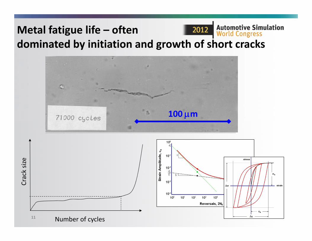
Metal fatigue life – often dominated by initiation and growth of short cracks
100 m
Number of cycles
Crack size
12
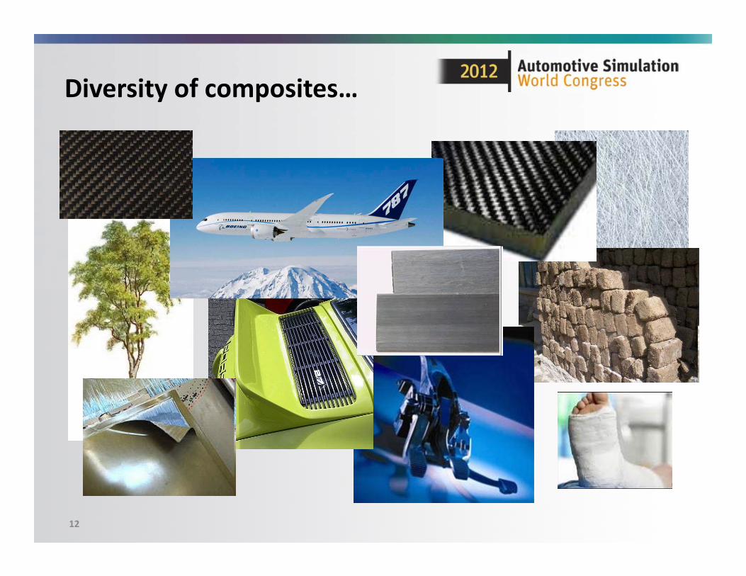
Diversity of composites…
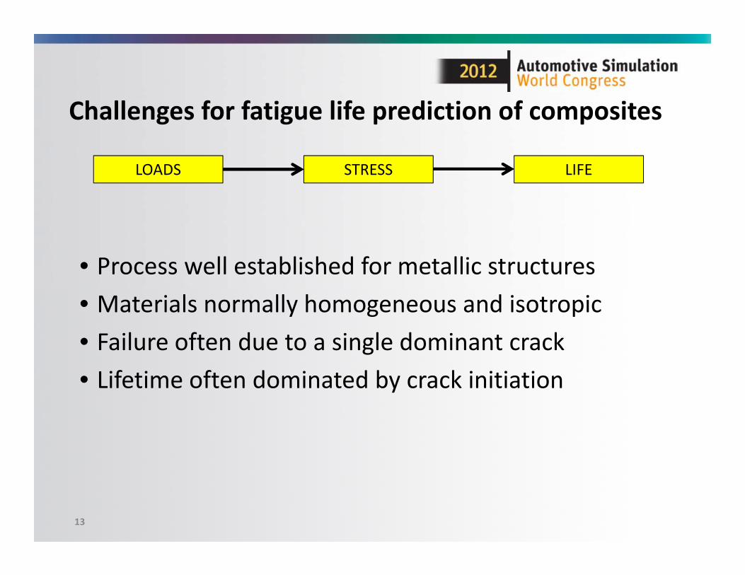
Challenges for fatigue life prediction of composites
13
LOADS STRESS LIFE
• Process well established for metallic structures• Materials normally homogeneous and isotropic• Failure often due to a single dominant crack• Lifetime often dominated by crack initiation
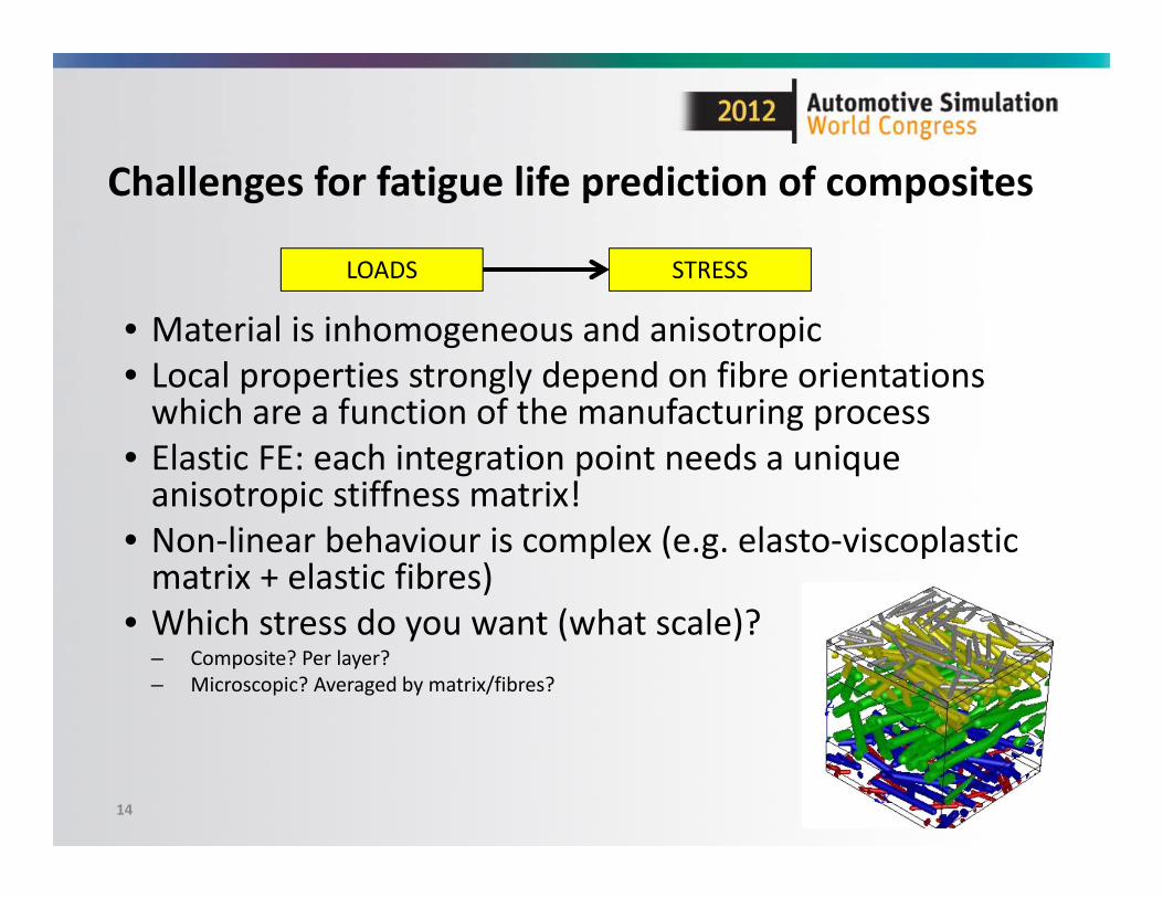
Challenges for fatigue life prediction of composites
• Material is inhomogeneous and anisotropic• Local properties strongly depend on fibre orientations which are a function of the manufacturing process
• Elastic FE: each integration point needs a unique anisotropic stiffness matrix!
• Non‐linear behaviour is complex (e.g. elasto‐viscoplasticmatrix + elastic fibres)
• Which stress do you want (what scale)?– Composite? Per layer?– Microscopic? Averaged by matrix/fibres?
14
LOADS STRESS
15
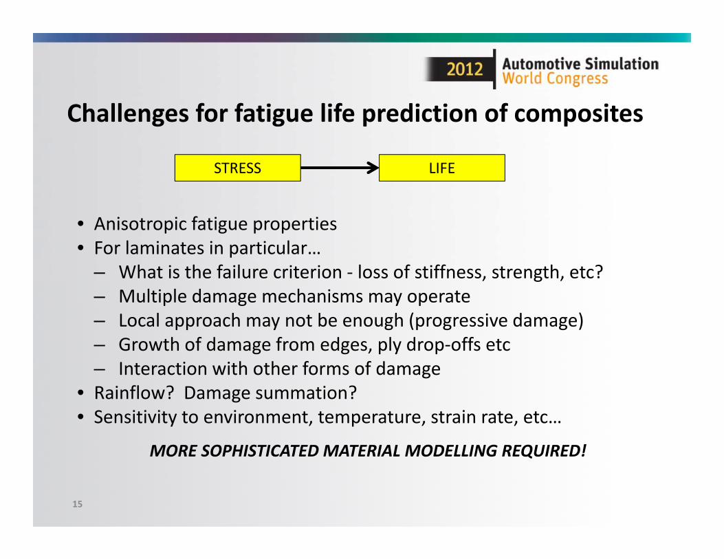
Challenges for fatigue life prediction of composites
• Anisotropic fatigue properties• For laminates in particular…
– What is the failure criterion ‐ loss of stiffness, strength, etc?– Multiple damage mechanisms may operate– Local approach may not be enough (progressive damage)– Growth of damage from edges, ply drop‐offs etc– Interaction with other forms of damage
• Rainflow? Damage summation?• Sensitivity to environment, temperature, strain rate, etc…
MORE SOPHISTICATED MATERIAL MODELLING REQUIRED!
STRESS LIFE
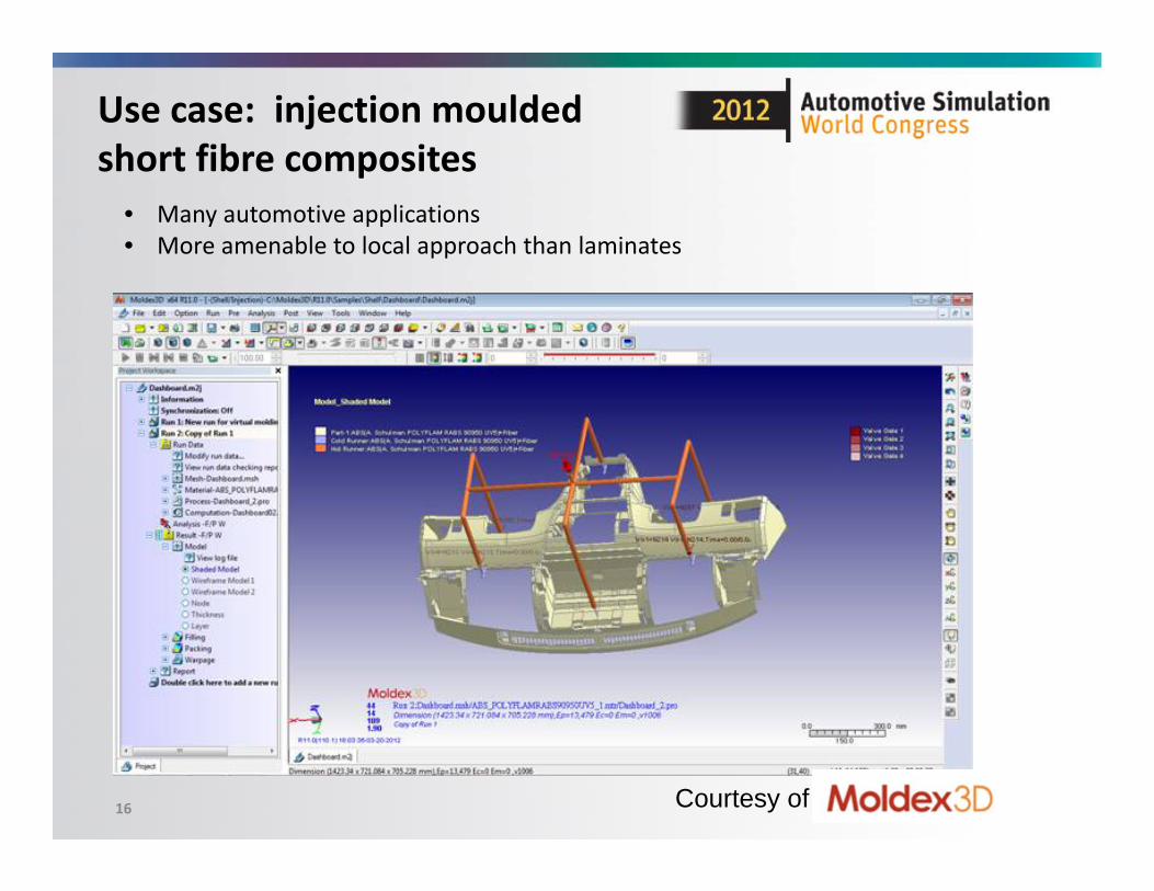
16 Courtesy of
Use case: injection mouldedshort fibre composites
• Many automotive applications• More amenable to local approach than laminates
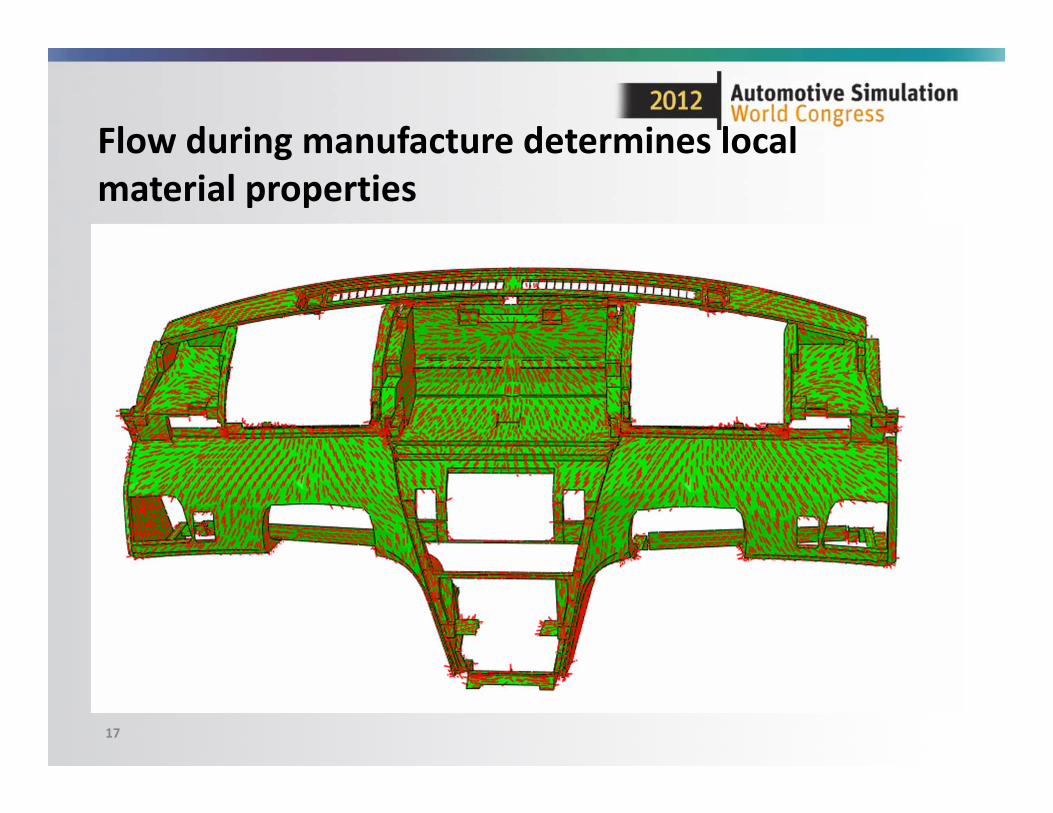
Flow during manufacture determines local material properties
17
18
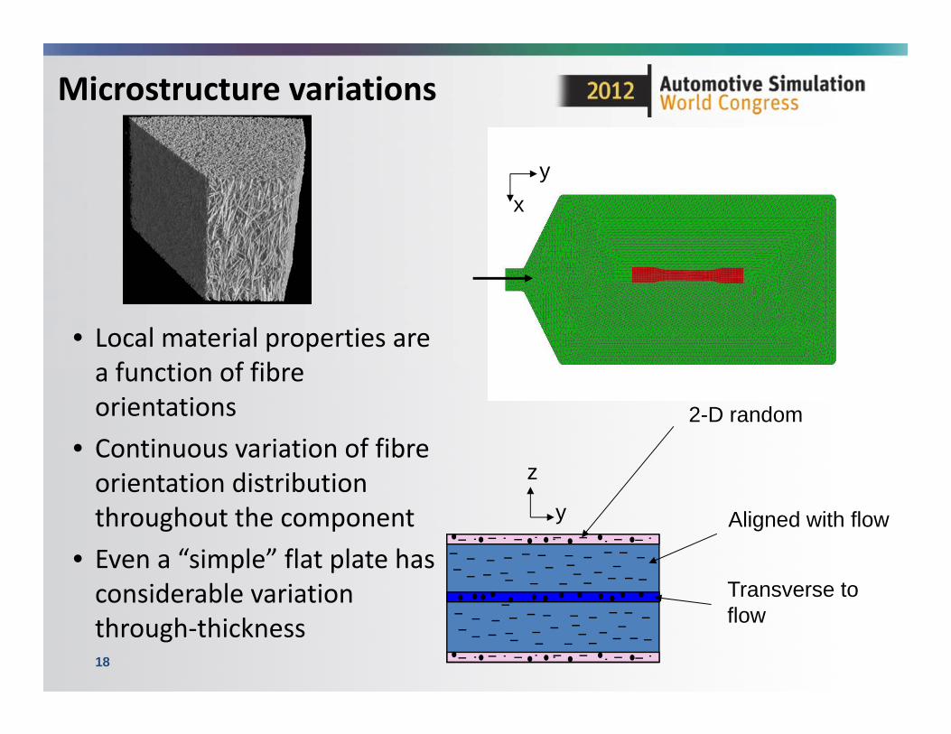
Microstructure variations
yx
Transverse to flow
2-D random
Aligned with flowy
z
• Local material properties are a function of fibre orientations
• Continuous variation of fibre orientation distribution throughout the component
• Even a “simple” flat plate has considerable variation through‐thickness
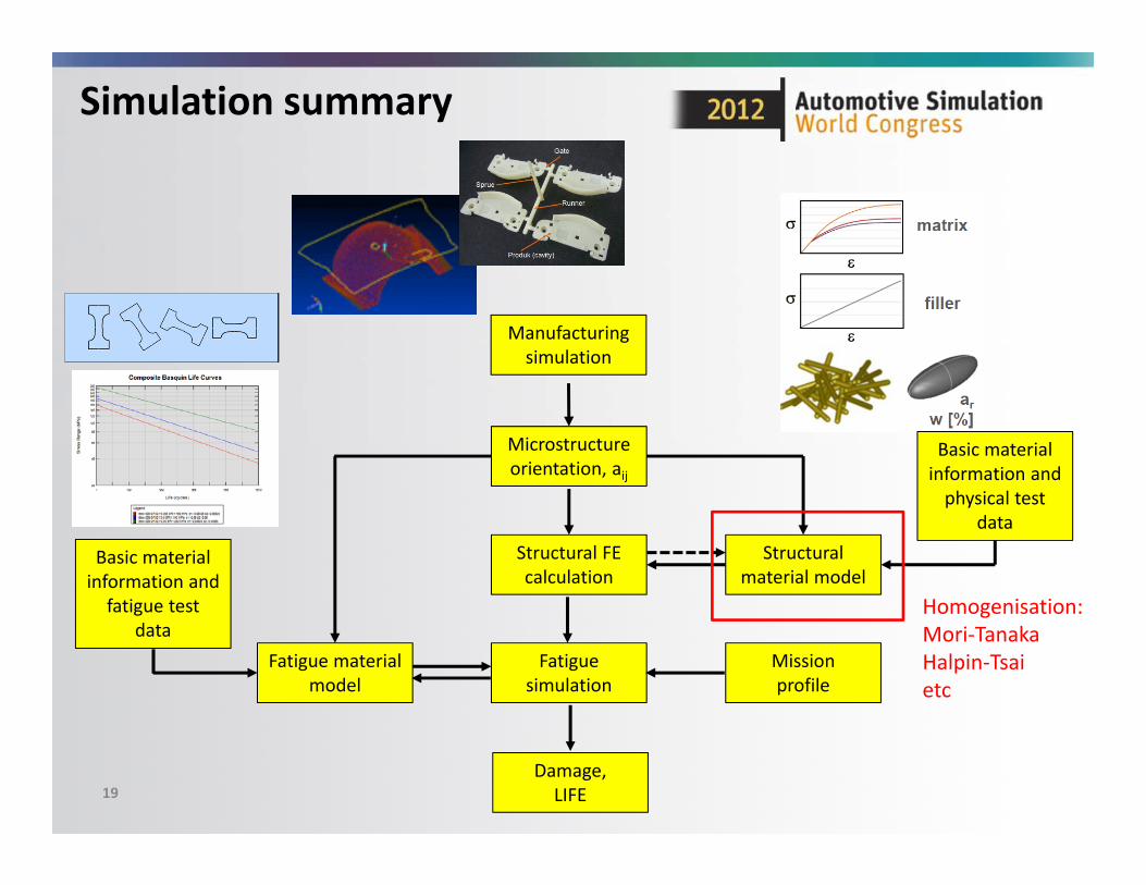
Simulation summary
19
Manufacturing simulation
Microstructureorientation, aij
Damage,LIFE
Structural FE calculation
Fatigue simulation
Missionprofile
Structural material model
Basic material information and physical test
data
Fatigue material model
Basic material information and fatigue test
dataHomogenisation:Mori‐TanakaHalpin‐Tsaietc
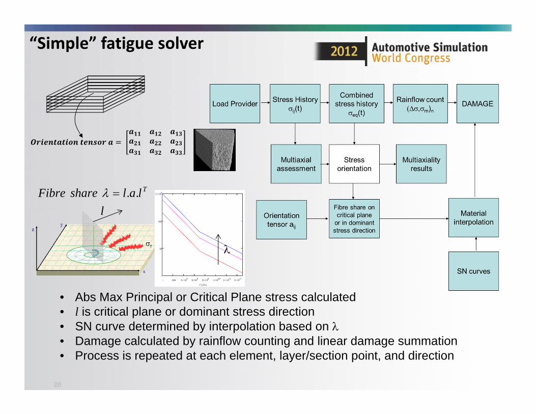
“Simple” fatigue solver
20
• Abs Max Principal or Critical Plane stress calculated• l is critical plane or dominant stress direction • SN curve determined by interpolation based on • Damage calculated by rainflow counting and linear damage summation• Process is repeated at each element, layer/section point, and direction
TlalshareFibre ..
l
21
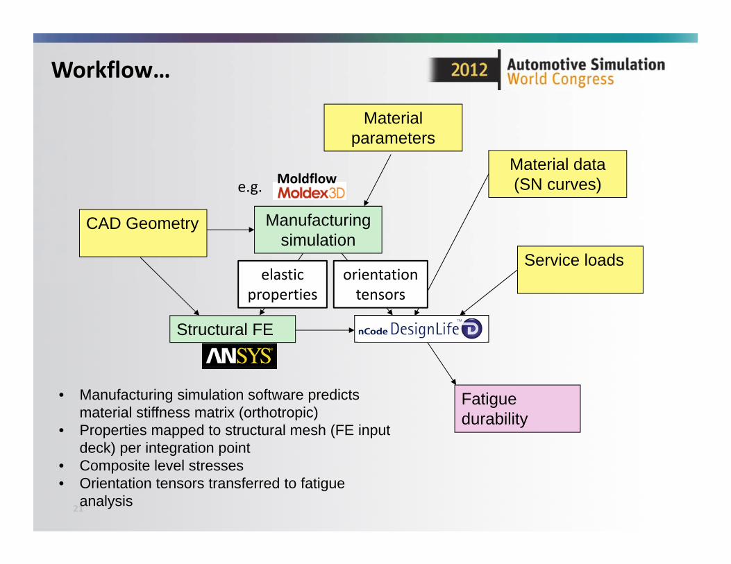
Workflow…
CAD Geometry Manufacturing simulation
Material data (SN curves)
Structural FE
Service loads
• Manufacturing simulation software predicts material stiffness matrix (orthotropic)
• Properties mapped to structural mesh (FE input deck) per integration point
• Composite level stresses• Orientation tensors transferred to fatigue
analysis
Fatigue durability
Material parameters
elastic properties
orientation tensors
Moldflowe.g.
22
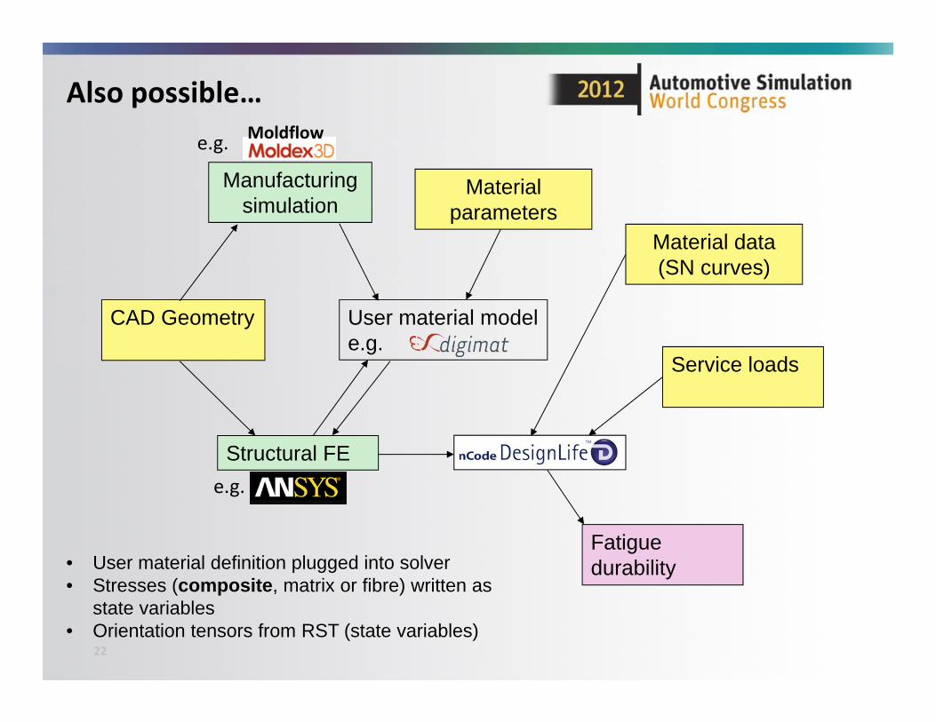
Also possible…
CAD Geometry
Manufacturing simulation
Material data (SN curves)
Structural FE
Service loads
Material parameters
• User material definition plugged into solver• Stresses (composite, matrix or fibre) written as
state variables• Orientation tensors from RST (state variables)
User material model e.g.
Fatigue durability
Moldflowe.g.
e.g.
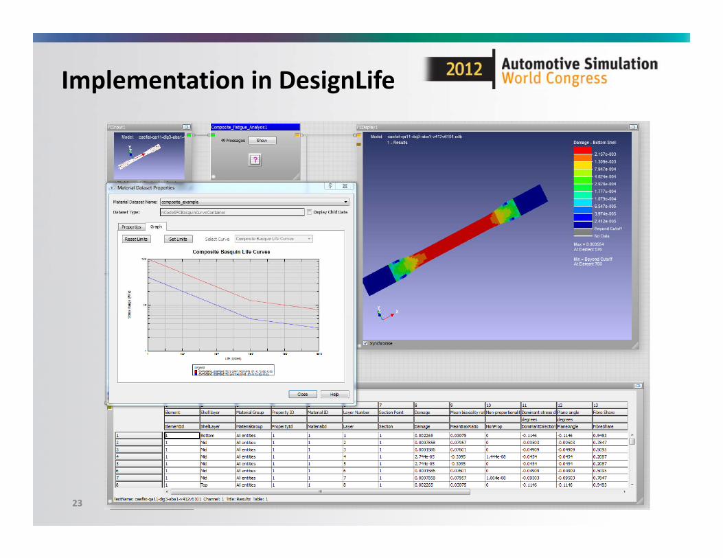
Implementation in DesignLife
23
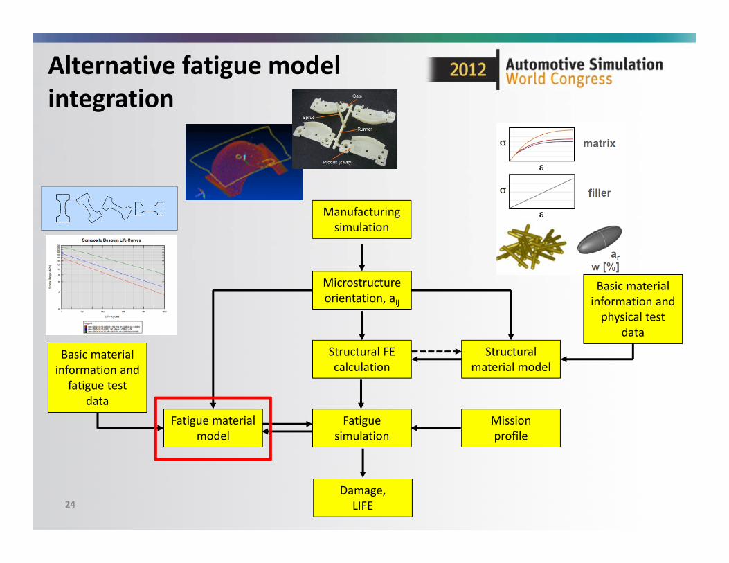
Alternative fatigue modelintegration
24
Manufacturing simulation
Microstructureorientation, aij
Damage,LIFE
Structural FE calculation
Fatigue simulation
Missionprofile
Structural material model
Basic material information and physical test
data
Fatigue material model
Basic material information and fatigue test
data
DIG
IMA
TOutputInput
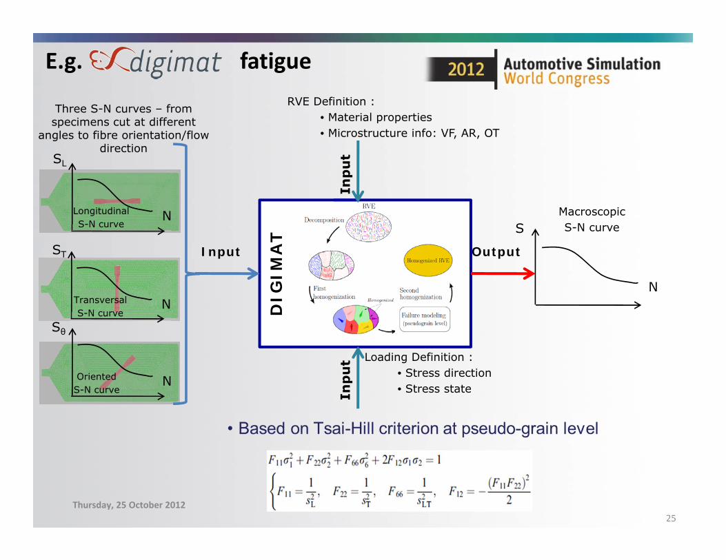
E.g. fatigue
Thursday, 25 October 201225
MacroscopicS-N curveS
N
SL
N
ST
N
Sθ
N
LongitudinalS-N curve
TransversalS-N curve
OrientedS-N curve
RVE Definition : • Material properties• Microstructure info: VF, AR, OT
Loading Definition :• Stress direction• Stress state
Three S-N curves – from specimens cut at different
angles to fibre orientation/flow direction
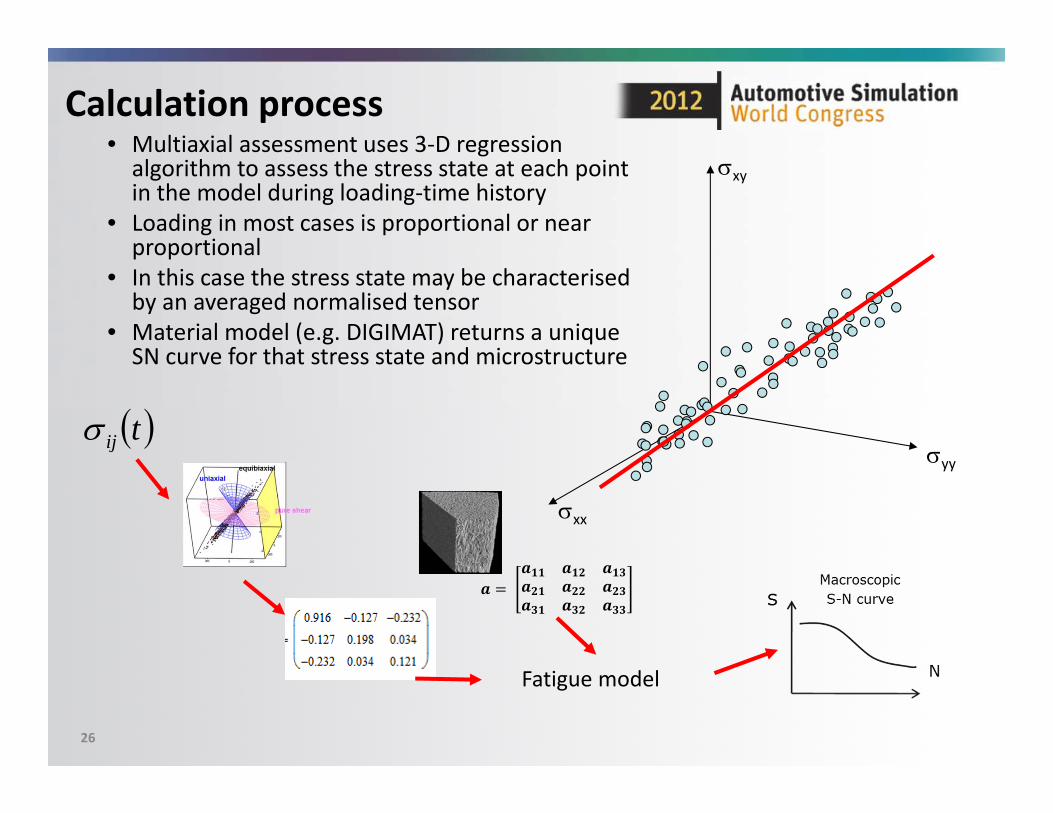
Calculation process• Multiaxial assessment uses 3‐D regression algorithm to assess the stress state at each point in the model during loading‐time history
• Loading in most cases is proportional or near proportional
• In this case the stress state may be characterised by an averaged normalised tensor
• Material model (e.g. DIGIMAT) returns a unique SN curve for that stress state and microstructure
26
xx
yy
xy
tij
Fatigue model
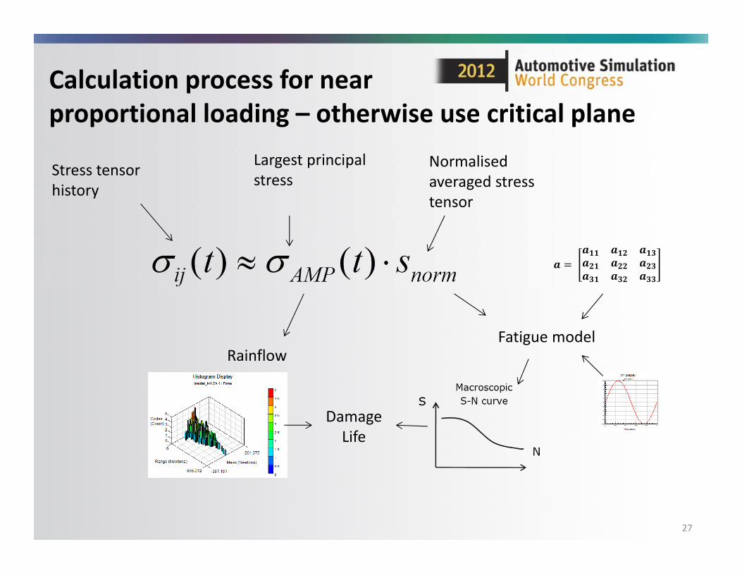
Calculation process for nearproportional loading – otherwise use critical plane
27
Stress tensor history
Largest principal stress
Normalised averaged stress tensor
Rainflow
Damage Life
Fatigue model
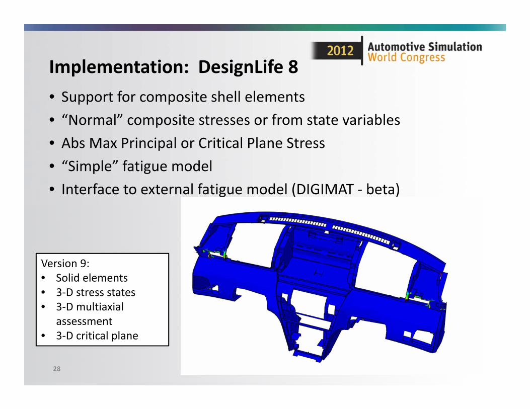
Implementation: DesignLife 8• Support for composite shell elements• “Normal” composite stresses or from state variables• Abs Max Principal or Critical Plane Stress• “Simple” fatigue model• Interface to external fatigue model (DIGIMAT ‐ beta)
28
Version 9:• Solid elements• 3‐D stress states• 3‐D multiaxial
assessment• 3‐D critical plane
Further work…
• Validation cases• Alternative damage models• Refine material characterisation methods• Stress gradients (notch effect)• Temperature, moisture content, mean stress effects…• Laminates…
Thursday, October 25, 2012 2012 Automotive Simulation World Congress 29
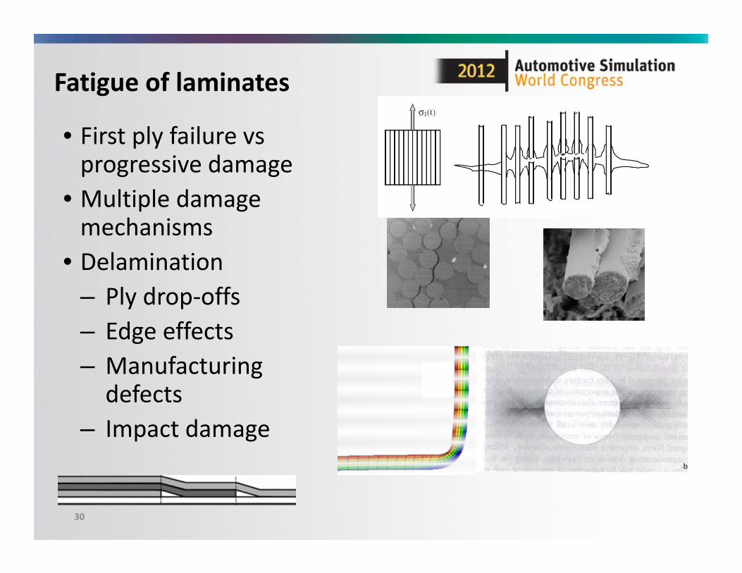
Fatigue of laminates
• First ply failure vsprogressive damage
• Multiple damage mechanisms
• Delamination– Ply drop‐offs– Edge effects– Manufacturing defects
– Impact damage
30

Thanks for listening … questions?
Presented by:Dr Peter HeyesHBM UK [email protected]
Thursday, October 25, 2012 2012 Automotive Simulation World Congress 31