title on the buckling strength of angles in transmission ... · 1. damages of transmission towers...
TRANSCRIPT
Title On the Buckling Strength of Angles in Transmission Towers
Author(s) WAKABAYASHI, Minoru; NONAKA, Taijiro
Citation Bulletin of the Disaster Prevention Research Institute (1965),15(2): 1-18
Issue Date 1965-11-30
URL http://hdl.handle.net/2433/124702
Right
Type Departmental Bulletin Paper
Textversion publisher
Kyoto University

Bulletin of the Disaster Prevention Research Institute, Vol. 15 , Part 2, No. 91, Nov., 1965
On the Buckling Strength of Angles in Transmission Towers
By Minoru WAKABAYASHI and Taijiro NONAKA
(Manuscript received September 30, 1965)
Abstract
It is assertained that -buckling or instablility of angles has been the main cause of destruction of the super-structure of transmission towers due to typhoons. Experimental
studies are made of buckling strength of angles, using structural steel with a L-90 mm x 90 mm x 7 mm profile. Various eccentricities and slenderness-ratios are included. Be-
havior and modes of buckling failure are observed. Test results are compared with buckling theories, and a general consensus is reached between them. As an approach
for safe and economical design of steel transmission towers, safety factors are examined for actual angle members based on the experimental results of the carrying capacity. Revision of JEC allowable stress is proposed.
Nomenclature
A cross-sectional area c core radius
ot warping constant E Young's modulus e eccentricity
ex eccentricity in x-direction ey eccentricity in y-direction G shear modulus
Iv torsion constant Ix moment of inertia with respect to x-axis
moment of inertia with respect to y-axis
ip 1/Ix+Iv
A
i2v y2m L initial-curvature constant
1 length of angle m eccentricity ratio
n eccentricity constant P compressive force ^ radius of gyration
rmax maximum radius of gyration r min minimum radius of gyration
fIz rxJ A y(x2-1-y2)dA
thickness of leg w width of leg
x coordinate along asymmetric principal axis of cross-section

2 M. WAKABAYASHI and T. NONAKA
y coordinate along symmetric principal axis of cross-section yia distance of shear center from x-axis
coordinate along angle axis effective slenderness ratio
2a ratio of actual length to minimum radius of gyration a axial stress
cc critical stress ay yield point stress
•torsional angle cot initial torsional angle
•ratio of tangent modulus to Young's modulus Poisson's ratio
va safety factor in actual condition va safety factor in ideal condition
displacement of shear center in x-direction •displacement of shear center in y-direction Primes denote differentiation with respect to z.
Table of Contents pages
1. Damages of Transmission Towers due to Typhoon 2 2. Buckling Tests on Angles 4
(1) Scope of the tests 4 (2) Test specimen 5 (3) Loading equipment 5
(4) Deformation measurement 6 (5) Behavior and buckling mode 6 (6) Experimental results 7 (7) Buckling theories 7 (8) Comparison and discussion 10
3. Allowable Buckling Stresses 13 (1) Carrying capacity of tower angles 15 (2) Safety factors of tower angles 16 (3) Discussion of allowable stress 17
Summary 17 Acknowledgment 17 Bibliography 17
1. Damages of Transmission Towers due to Typhoon
It is often observed that transmission towers get damaged by typhoons, which almost regularly hit Japan. Reportedly, destructive typhoons take
place once every few years somewhere in this country. In recent years, for example, Isewan Typhoon hit the middle part of Japan in 1959, and Muroto Typhoon II hit the western part in 1961, both having caused enormous damage to steel transmission towers. Among 13,563 towers, 63 were completely destroyed
by Isewan Typhoon ; 66 were about to collapse ; 8 suffered some damage (1p* ; * Numbers in square brackets refer to the Bibliography at the end of the paper .

On the Buckling Strength of Angles in Transmission Towers 3
hence, approximately one per cent of steel transmission towers got damaged in one way or another in this single typhoon.
In view of the fact that a great number of towers are constructed or repaired year after year, even a little saving of material is desirable in each tower member. In order to gain access to safety and economy re-quirements, we first have to know the causes or the mechanism of tower failures. Fig. 1 shows an example of collapsed transmission towers. It is not an easy task to find the direct cause for failures, but statistics show the
f'- 4
-16i---, i---- - i ,/,g,,..... '‘,45.,','.;:"'-- -7: 2t'1'1'-°""'?itt':'"46,v4'S Wtfik'/q1,_/ /'r,y-Q,,,--,,,,1 ',,/,''`,
A
V%.7.,.''''''.
..' ', 4".1610 4iasit,..$0 ,,,. , , 4 W‘
Fig. 1. Collapsed steel tower due to typhoon.
dominant cause is slipping of nolk ti f
oundations from the ground.,
r Either a foundation turns overe or the post members slip ' Ai&
through the foundation con-ag. , crete. Improvement and
minute care in the construc- ..24 - '1 tion or design method are ‘,..Ablk Tqf ,i," believed to greatly decrease these failures. What comes next, but not less important, o' is the failure in the super- - structure. Most of failures in the super-structure are, considered to be caused di------AY ",
, , -,••^
rectly or indirectly by buckl-ing of compression members.5,2, 5 •- This is particularly true in 7 large steel transmission towers , , 5' - i / i..,i;,,,f=/I°
•
'5t ./-'-,) C2J. Ishizaki, Ishida and , ----1- i , let, Kawamura performed an ex- / , i r4 .iff. '
, -1
periment creating a model, with the proto-type scale of aFig. 2. Buckling failure of angle in steel tower. collapsed tower C3J. Fig. 2 is the picture of the tested tower model, which

4 M. WAKABAYASHI and T. NONAKA
indicates the importance of buckling phenomena in a compression member of a steel tower.
Design regulations of steel transmission toweres in this country are based on results of tower tests which have proto-type complications, and yet few experimental results seem to be available on buckling of a single member.
Among compression members of steel towers, most posts are subjected to nearly central thrust, and they are not so slender ; web members are mostly composed of an angle section, being connected at their legs to the main posts directly or through gusset plates. Hence, web members are apt to get eccen-tricity, and they are in addition often quite slender. Some constraints on the web members by posts have been considered to compensate the decrease in their buckling strength due to eccentricity, and for the design of a web member, it has been supposed to be simply supported at its ends. To ra-tionalize the design method, however, the effects of .the eccentricity and the constraints should be studied separately. Apart from the latter effect, we carried out some buckling tests and studied the behavior of angles under central and eccentric thrust.
2. Buckling Tests on Angles
(1) Scope of the tests A total of fifty-seven specimens of mild steel angles L-90 mm x 90 mm X
7 mm were tested and compared with buckling theories. The test program employed six kinds of eccentricity as shown in Fig. 3 (a). Solid circles show
r max e
x2 17.4mm, ey r,in= 17.7mm
t NeY Series 1 Series 2 Serifs 3 Central loading Eccentric loading Eccentric loading
on the symmetric axis on the symmetric axis
y+1
Series 4 Series 5 Series 6 Eccentric loading Eccentric loading Central loading
on the asymmetric with respect to with initial torsion principal axis both principal axes
Fig. 3 (a). Eccentricities.
the points of load application. Series 1 is the central loading ; Series 2 and 3 are eccentric loading on the symmetric axis of the cross-section ; Series 4 on asymmetric principal axis. Series 5 has eccentricity with respect to both
principal axes. Series 6 has initial torsion, and is subjected to central thrust. Amounts of eccentricities are also shown in the figure. r, and rmtn are
On the Buckling Strength of Angles in Transmission Towers 5
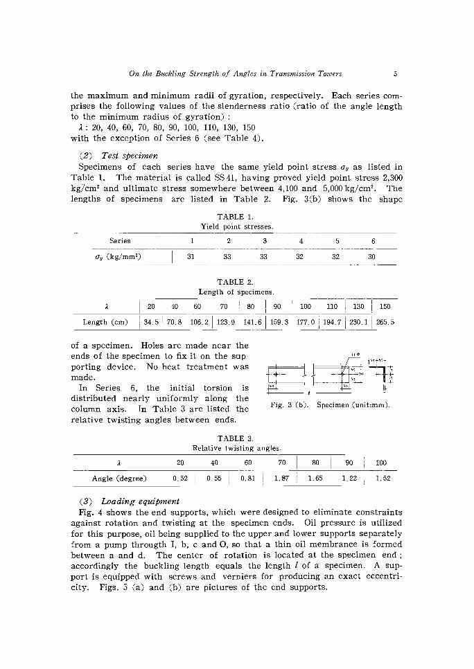
the maximum and minimum radii of gyration, respectively. Each series com-prises the following values of the slenderness ratio (ratio of the angle length to the minimum radius of gyration) :
2: 20, 40, 60, 70, 80, 90, 100, 110, 130, 150 with the exception of Series 6 (see Table 4).
(2) Test specimen Specimens of each series have the same yield point stress ay as listed in
Table 1. The material is called SS 41, having proved yield point stress 2,300 kg/cm' and ultimate stress somewhere between 4,100 and 5,000 kg/cm'. The
lengths of specimens are listed in Table 2. Fig. 3(b) shows the shape
TABLE 1. Yield point stresses.
Series 1 2 3 4 5 6
cry (kg/mm2) 31 33 33 32 32 30
TABLE 2. Length of specimens.
2 20 40 60 70 80 90 100 110 130 150
Length (cm) 34.5 70.8 106.2 123.9 141.6 159.3 177.0 194.7 230.1 265.5
of a specimen. Holes are made near the ends of the specimen to fix it on the sup- "4, "t porting device. No heat treatment wast"5-t
made. ')-90 In Series 6, the initial torsion is 1401 i"°! 4.
distributed nearly uniformly along the column axis. In Table 3 are listed theFig. 3 (b). Specimen (unit:mm). relative twisting angles between ends.
TABLE 3. Relative twisting angles.
2 20 40 60 70 80 90 100
Angle (degree) 0.52 0.55 0.81 1.87 1.65 1.22 1.52
(3) Loading equipment Fig. 4 shows the end supports, which were designed to eliminate constraints
against rotation and twisting at the specimen ends. Oil pressure is utilized for this purpose, oil being supplied to the upper and lower supports separately from a pump througth I, b, c and 0, so that a thin oil membrance is formed between a and d. The center of rotation is located at the specimen end ; accordingly the buckling length equals the length 1 of a specimen. A sup-
port is equipped with screws and verniers for producing an exact eccentri-city. Figs. 5 (a) and (b) are pictures of the end supports.

6 M. WAKABAY ASHI and T. NONAKA
(4) Deformation measurement eir 1 mi, Deflections and torsions were gip/ . 1",11 measured bydial gauges set asI-.-__. A
..4.(fruia shown in Fig. 6.** Strains were o-.;0inhh i., _ also measured at various points--- -E-
by means of wire strain gauges.''' iMIN^It..0um,m1,_zon.mm.IMI
...3. These measurements were madeI
I.1111.117Mi. for observing the behavior of71 ._. lag, compressed angles. Specimento••••7"
(5) Behavior and buckling ea1.1-=---n mode,-----71,
=inr.=i.7
.. EI7iMiliMEMic1 • •
(i) Series 1 (Central loading) Long angles do not show'E.-lir o-7.&
.010 appreciable deformation until/.1 1••• the maximum loads are reached. They buckle relatively gradually Fig. 4. End supports. in the direction of the symmetric axis of the cross-section. Pomo••
,i;egtt1-1.4 with slenderness ratios between ,' 1
70 and 100 buckle suddenlyft-..1
0
''i v. Me , 4
11 1 -i, L----i 1 . 1 Fr — lir - 111 .. * ----.•
,
I _ 1 . ....--, - — Z , ele
,.! i 1, z c-, i--1
,, stilito • ,, ,. 1r IP • 1/,
'' l .."11 . ': ofp• , ,..
..r \ ir _ IP
Olt•Vi: f ,••• •• IA. ,
Fig. 5 (a). Upper support.,,,,-I.1: ,g
.
• ,: •%', • t ,
. •-
, Z. • .
1 - .,, [ e;, r
' •A ' 6 - 7. -: - - .. ' - - . - 4 , , I ; , I I i ' ' ' '
\ ,, . . ....-
iii' tL'• '.... I 4... e.7"i .: '-il t -A
.
Fig. 5 (b). Lower support. Fig. o. Deformation measurement.
** Measurement device is described in detail in another paper CM).
On the Buckling Strength of Angles in Transmission Towers 7
under the buckling loads.*** Torsional deformation plays an important role in the buckling phenomena for short angles with slenderness ratio less than 70.
(ii) Series 2 (Eccentric loading on the symmetric axis) Deflection increases steadily in the opposite direction to the eccentricity
as the load increases.*** The cross-section does not change its shape until very large deflections are acquired after the maximum load is reached.
(iii) Series 3 (Eccentric loading on the symmetric axis) Behavior is similar to Series 2 until the maximum load is reached. Since
the eccentricity is given near the adjoing point of the legs, local buckling
phenomena are not observed. (iv) Series 4 (Eccentric loading on the asymmetric principal axis)
For small loads angles tend to deflect to the direction opposite to the eccentricity.*** As the loads approach the maximum loads their deflections increase rapidly in the most flexible direction, being accompanied by torsional deformation. Bending deformation dominates in long angles, but torsional or local deformation in short angles.
(v) Series 5 (Eccentric loading with respect to both principal axes) Buckling phenomena take place quite slowly with increasing deflections
and torsions as loads increase. Local buckling also happens in short angles.
(vi) Series 6 (Central loading with initial torsion) Torsion increases steadily with the load. Bending deformation resembles
that in Series 1.
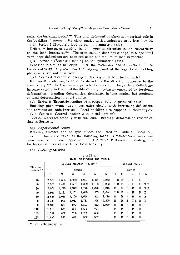
(6) Experimental results Buckling stresses and collapse modes are listed in Table 4. Measured
maximum loads are taken as the buckling loads. Cross-sectional area has been measured for each specimen. In the table, B stands for bending, TB for torsional flexural and L for local buckling.
(7) Buckling theories
TABLE 4. Buckling stresses and modes.
Buckling stresses (kg/cm2) Buckling modes
— ness ratio Series Series
1 2 3 4 5 6 1 2 3 4 5 6
20 2,960 1,638 1,932 1,907 1,417 2,860 TBB B L L L
40 2, 960 1, 446 1, 561 1, 832 1, 183 2, 850 TB B B L L T B
60 2,873 1,219 1,342 1,740 1,046 2,815 B B B B B TB
70 2, 923 1, 121 1, 252 1, 638 953 2,644 TBB B B B B
80 2 644 1, 055 1,160 1, 696 892 2,719 B BBB BB
90 2, 338 966 1, 041 1, 731 828 2,295 B B B TBB B
100 2, 208 884 977 1, 591 813 1,980 B BBB BB
110 1,913 809 867 1,623 777 B BBB B
130 1, 327 667 738 1, 282 680 B BBB B
150 1,000 580 619 968 552 B BBB B
*** See Bibliography 15.

8 M. WAKABAYASHI and T. NONAKA
Let x and y be the coordinate axes along the principal axes of the angle cross-section as shown in Fig. 7. z-axis is taken along the column axis.
(i) Flexural buckling Under the central thrust, bending about x-axis occurs
independently, unless local buckling takes place, and the buckling stress a, is given in the elastic range from Euler's theory Fig. 7.
2.E.2E cc= 12(1)
where E is the Young's modulus. For inelastic buckling, the tangent modulus theory gives
it.2rE ac= 12 (2)
where r is the ratio of tangent modulus to Young's modulus. According to DIN 4114 C4), r can be approximated as
(\ 2 r=1—( (3) ay—a2,
for stress a such that cr,�6,-�ay, and ap:;_--'0.8ay where up 1114141 is the proportional limit and cry is the yield stress. -
(iii) Local buckling Since an angle is composed of plate elements, i. e., two
legs, it is possible that, before the inception of instability due to integral failure of the column, the legs reach a state of unstable equilibrium and buckle locally. In case of an equal angle under central thrust, the local buckling -
!Mitt can be approximately analysed as for a plate element+—.-F
which has dimensions of a leg of the angle and is simply supported along three edges with the other edge free as shown in Fig. 8. With notations given in the figure, and with Poisson's ratio 12, the critical stress for such a plate is given by Bleich C5) as Fig. 8.
7r2Ev r \2/w2 cc= 12(1 - ti2A w)11425 i/r (4) /2
When the length of the angle is very long compared with the width of its legs, this is approximated as
Tr2Ev7r(t 2 ac---0.42512(1—to)w)(5)
(iii) Torsional flexural buckling Assuming the shape of the cross-section does not change due to buckling,
Kollbrunner and Meister C6) give the equilibrium relation in the elastic range for slightly bent angles under eccentric thrust P as

On the Buckling Strength of Angles in Transmission Towers 9
ElvE'"' +PE" + P(ym— ew)CO" = 0
EIxv" +.1372" + Pexco" =0 (6) EC
M9"" +-CP(ip2 + ym2) — GID + Pey(rx— 2ym)}9"
+ P(ym— ey)E" + Pexv" = 0
where E, z : displacements of the shear center in x- and y-directions ex, ev : eccentricities in x- and y-directions
: torsional angle 4, 4: moments of inertia of the cross-section with respect to x- and
y-axes : torsion constant
G : shear modulus : warping constant with respect to shear center
y : distance of shear center from x-axis 4 ip2=Ix+
A i2112=ip2
c ym2 1 rx= Ix3X2312)dA A : cross-sectional area
and primes denote differentiation with respect to z. If we use boundary conditions that at z =0 and 1
(7)
then the critical stress for elastic torsional flexural buckling is given as the smallest root of the following equation :
ey (r — 2 y (ax— ac) (ay — Ge) v{0 t Ge Ere 1,12 M—ex2 — ac2(ax— ae).ay20.0 - 2 = 0 (8) (Y)
21,126'02
where
7r2EIx ax= Al2
r2Ery 621— Al2(9)
1 r2 0-EC,=Aim2(wD+ 12A2) It is recalled that 2— 1and that rmiy2 = rybin A
For central loading, ex e, = 0 and tangent modulus theory allows Eq. (8) to be used for inelastic range also, provided E and G are multiplied by r, or equivalently
(6rxcr,O'igeac2 YM2 r)"{(611—c)(CI—)iM2 (10)
10 M. WAKABAYASHI and T. NONAKA
Bleich (7) has shown that for an equal angle under central thrust the tor-sional flexural buckling theory and the local buckling theory give approximate-ly equal value of the critical stress. Clearly, Series 1 and 6 correspond to the condition that ex=ey=0; Series 2 and 3 =0, ey*0 ; Series 4 e.*0, ey=0 ; Series 5 ez0, ey*O.
In case of the experiment reported herein, the boundary conditions are such that the displacements, bending moments, twisting moments and warpings vanish at both ends, but the difference in the solutions between these boundary conditions and Eq. (7) is found to be small C8DC9D ; Eq. (7) gives much simpler solution. For these reasons, we use above solutions in the present
paper. (iv) Jeiek's theory
The torsional flexural buckling theory does not hold in inelastic range for eccentric loading. It is noted that in Series 2 and 3 the carrying capacity is controlled by bending in the symmetric plane of an angle An approximate analysis is presented for inelastic bending in such a case by Jeiek (10). As-suming elastic-perfectly plastic behavior of the material, we can approximate-ly determine the maximum stress ac from
3( 6'—1)—mr 2Eir2Em3 22_ ac3( —1lif 22�9ay(3m)(11)
and
22_ 702E / 6c o-y a, 2\3 2r2Em3 (— ay'V ay \ay3mif22<96,(3 — m)12)
where m is the ratio of the eccentricity ey to the core radius in the compres-sive side. Eq. (11) is valid when yielding occurs only in the compressive side and Eq. (12) when yielding occurs both in the tensile and compressive sides.
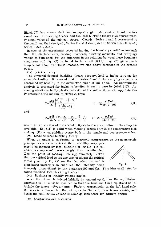
(v) Modified local buckling theory When an angle is subjected to eccentric compression on the asymmetric
principal axis, as in Series 4, the instability may pri- I0 marily be induced by local buckling of leg OE (Fig. 9), which is compressed more strongly than the other leg.
C is the point of loading. We approximately reckon that the critical load is the one that produces the critical
stress given by Eq. (5) on that leg when the load is distributed uniformly on each leg, the intensity being Fig. 9. inversely proportional to the distances BC and CA. This idea shall later be called modified local buckling theory.
(vi) Buckling of initially twisted angles When the column is twisted initially by amount coi(z), then the equilibrium
equations in (6) must be modified so that the first and third equations of (6) include the terms —Pymyoi" and —PiAi2oi", respectively, in the left hand side. When got is a linear function of z, as in Series 6, these terms vanish, and hence the equilibrium equations coincide with those for straight angles.
(8) Comparison and discussion

On the Buckling Strength of Angles in Transmission Towers 11
Experimental results and the predictions from the above buckling theories are cofnpared in Figs. 10-14. In Fig. 14 the ordinate is proportional to the critical stress, and the abscissa to the slenderness ratio, both being dimen-sionless.
(i) Series 1 Fig. 10 shows that the experiment has close agreement with Euler's theory,
Eq 1(1) for long columns, with tangent modulus theory, Eq. (2) for me-
0..(kg/cm2) 'reagent-Modulus Theory
30003000•
Zeal Bucklin:411k Theory
/1\7 2000 2000 — s•r;°' 2
-
Mar's Theory
a...
• . Test Results
O 50 100 150 A 50 100
Fig. 10. Series 1. Fig. 11. Series 2 and 3.
0,(hg/em2) 0.c I keicrn2 7000 3000Thesry
Ls I .7,41k
2000 Modified Local Ouckling Theory '000
•
O tin red •
Theory
f000 Toreiona l- loon
_ "M;7!• BucklingTheory
O : Test Results
50 100 150 A 0 100 150
Fig. 12. Series 4. Fig. 13. Series 6.
dium' lengths, and with the torsional flexural buckling theory, Eq. (10) or the", local buckling theory of plate elements, Eq. (4) for short columns. It was
observed during the experiment that angles with 2 less than 62 buckled due to torsion combined with bending, exactly as the torsional flexural buckling theory predicts.
(ii) Series 2 and 3 General agreement is seen between the experiment and Jeiek's theory in

12 M. WAKABAYASHI and T. NONAKA
Fig. 11.
(iii) Series 4 Straight line labelled as linearized theory in Fig. 12 is obtained by connect-
ing the point corresponding to the elastic limit strength by short column theory, with zero length, to the point correponding to the state where the elastic limit stress is reached somewhere in the column according to torsional flexural buckling theory, Eq. (8). We see that the experimental results agree
with the torsional flexural buckling theory for long angles, and they lie for
Pc c-
Tangent-Modulus Theory 1 . o•Series 1 LocalBucklingg1-eory . Series 2
0.9 4:ocll Buckling Theory (Series 1) • zA. x Series 3
0.8 0 Series 4
0.7 Series 5 •
Aiks. 'Modified Local Buckling Theory 1, A Series 6
0.6 - x Formula Test Results
0.5,,Euler's Theory Linearize.
Theory
a • ,JeZek's Theory o
. 4 (Series 2) 0
Zr a Jeiek's Theory • (Series 3) Torsional- •
0.3 a Flexural aBuckling Th
eory a a
0.2
0.1
0 1 I I I I 1 1 1 I 1 1 1 1 I 1 1 1 1 I 0 0.5 1.0 1.5 A
minFi Fig. 14. Comparison among series.
On the Buckling Strength of Angles in Transmission Towers 13
inelastic range between the predictions from the modified local buckling theory and the linearlized theory.
(iv) Series 6 As mentioned already, theories predict the same critical stresses for Series
6 and 1. This is confirmed in the experiment as is seen in Figs. 13 and 14.
(v) Comparison among series In Fig. 14 are compared all test results. Theoretical curves are included in
the figure. An empirical formula is also added with a chain line for short and medium lengths in Series 4, obtained from the method of least squares.
It is seen both experimentally and theoretically that the buckling strength or the carrying capacity is decreased by eccentricities, and that Series 5, which has eccentricities with respect to both principal axes, has the smallest critical stresses. There is some difference in the effects of eccentricities on the symmetric axis and on the asymmetric principal axis. The eccentricity on the symmetric axis reduces the capacity for all angles. This is concerned with bending deformation ; bending occurs by considerable amount due to the eccentricity before the maximum load is reached, because of small flexural rigity for bending in the plane of symmetry, and this is well taken care of by applying, e.g., JeZek's theory. On the other hand, when we compare the theoretical and experimental results for Series 1 with those for series 4, we see that the decrease in the capacity due to the eccentricity on the asym-metric principal axis is not appreciable for long angles (for eccentricity of the amount given here). This is also seen when we compare the test results for Series 2 and 5. The decrease for short angles is primarily caused by local buckling or torsional deformation, but the carrying capacity of long an-
gles is primarily concerned with bending in the most flexible direction, i.e., in the symmeric plane.
3. Allowable Buckling Stresses
We will now examine the allowable buckling stresses based on the experi-mental and theoretical results presented in the previous section.
In this country, steel transmission towers are designed in accordance with
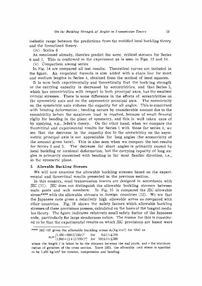
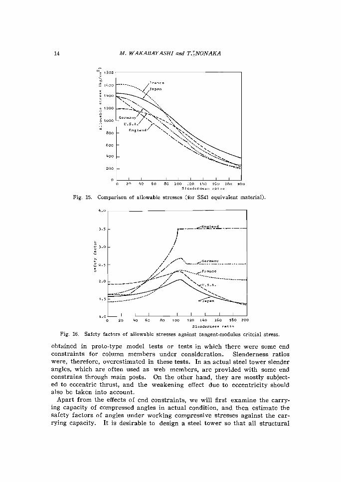
JEC (11). JEC does not distinguish the allowable buckling stresses between main posts and web members. In Fig. 15 is compared the JEC allowable stress**** with the allowable stresses in foreign countries (12). We see that the Japanese code gives a relatively high allowable stress as compared with other countries. Fig. 16 shows the safety factors which allowable buckling stresses of these provisions possess, calculated on the basis of the tangent modu-lus theory. The figure indicates relatively small safety factor of the Japanese code, particularly for large slenderness ratios. The reason for this is consider-ed to be that the experimental results on which JEC provisions are based were
**** JEC-127 gives the allowable buckling stress oa(kg/cm2) for SS41 as
J1 ,450 500(i/10002 for100 Ca_ t1,900+11+(//100r)21 for 100�1/r-�220
where the length 1 is taken to be the distance between the end joints, and r the minimum radius of gyration of the cross section. Since 1953, the allowable unit stress is specified to be 1,450 kg/cm2 for tension, compression and bending.
14 M. WAKABAY ASHI and T.7.NONAKA
1300
/France Japan
w • 1400
1200 •
• • 1000 —G7,17:17.".^\ England /s •
800 —NN•
•
600 —
400 _ "•^•, **••=,
.
200 —
o 111111111 0 20 4o 60 80 loo 120 140 16o 180 200
Slenderness ratio
Fig. 15. Comparison of allowable stresses (for SS41 equivalent material).
4.0
O— 3.0 —
4 2.5
..••••^- France •• 2.0 ______ Nr1J.S.A.
1.5 —__ ____ ____-,5;;
. ___Japan
1.0 0 20 40 60 80 100 120 140 160 180 200 Slenderness ratio
Fig. 16. Safety factors of allowable stresses against tangent-modulus critcial stress.
obtained in proto-type model tests or tests in which there were some end constraints for column members under consideration. Slenderness ratios were, therefore, overestimated in these tests. In an actual steel tower slender angles, which are often used as web members, are provided with some end constrains through main posts. On the other hand, they are mostly subject-ed to eccentric thrust, and the weakening effect due to eccentricity should also be taken into account.
Apart from the effects of end constraints, we will first examine the carry-ing capacity of compressed angles in actual condition, and then estimate the safety factors of angles under working compressive stresses against the car-rying capacity. It is desirable to design a steel tower so that all structural
On the Buckling Strength of Angles in Transmission Towers 15
members bear the same safety factor.
(1) Carrying capacity of tower angles As pointed out in the first section, post and web members are essentially
in different conditions in a steel tower. In order to determine the carrying capacity of a compressed angle, both cases of central and eccentric compres-sion must be clarified.
(i) Central loading From studies in the previous section, we have found that the buckling stress
is given from : a) Euler's theory, Eq. (1) for long angles,
b) tangent modulus theory, Eq. (2) for medium lengths, and c) local buckling theory of plate elements, Eq. (4) (or torsional flexural
buckling theory, Eq. (10)) for short angles. (ii) Eccentric loading
Some eccentricity is inevitable in angle members of a steel tower even with the greatest possible care in the construction. Furthermore, under normal conditions an angle has some initial deflection. Both of these effects reduce the carrying capacity of a compressed angle. The former may pri-marily depend on the size of the cross-section and the latter on the length of an angle. We approximately regard these effects as being produced by an eccentricity e composed of two terms, one of which is proportional to the radius of gyration r and the other to the length 1, i.e.,
r1 e = nL(13)
where constant n depends on the eccentricity of loading and L on the initial curvature, both being dimensionless and independent of the cross-section and the length.
The ratio m of the ecentricity e to the core radius c in the compressive side is
m= r(1 + aL) (14) cn
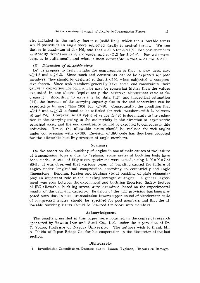
The constant r/c in Eq. (14) depends only on the shape of the cross-section. By examining actual angles which are often used in transmission towers in
this country, these constants are evaluated as shown in Table 5.
TABLE 5. Eccentricity constants
Constants Measured values Approximation
r 1.95 — 2.14 2
post 11.2 — 39.7 20
web 3.2 — 6.6 5
L 1,000 —13,000 1,000

16 M. W AKABAY ASHI and T. NON AKA
III/ Load/Point w 1111L.:.:entroid \:oading Point ixt-Centroidw 'I2
•
2 2 Fig. 17. Post member. Fig. 18. Web member.
These constants refer to the eccentricity on the symmetric axis of the cross-section. Due to connection mechanisms, post members generally have a little eccentricity on the symmetric axis as in Fig. 17, and web members have ec-centricity with respect to both principal axes as in Fig. 18. The eccentricity on the symmetric axis can well be taken care of by applying Jekk's theory, Eqs. (11) and (12). Although the eccentricity in the direction of the asym-metric principal axis, in web members, also reduces the carrying capacity, studies in the previous section have shown that the reduction is not serious for long angles. For short angles, this eccentricity induces considerable torsional deformation, and reduces, the carrying capacity appreciably. Review-ing the experimental results for Series 4, we estimate the maximum stress of short web members as sixty percent of the yield stress.
(2) Safety factors of tower angles Based on the carrying capacities thus calculated, safety factors of the al-
lowable stress of JEC provision have been evaluated for SS41 and are shown
graphically in Fig. 19. In the abscissa is taken the ratio 2a (apparent slen-derness ratio) of the actual length of an angle to the minimum radius of gyra-tion. The solid line shows the safety factor with respect to the carrying capacity for central loading, the chain line to post members, and the dotted line to web members.
106 Pc= 1840kg/cm2 2.0 Against
1.9 modulus
1.8
1•7 \Against\ X= 59.5 2 2203kg/cm "Against Euler
''6 local
Jelex, n . 20 (post) 1
.4 1.3
1,a Against 3-11 n= 0.8\\Against Jelek,n = 5 (web)
1.01—"7'„3 ,3D-5-0X1050 .070 80 90 100 Anperent slenderness ratio
Fig. 19. Safety factor of JEC allowable stress (SS41).
It should be noted that the JEC allowable stress bears different values of the safety factor va for post and web members in actual conditions. In the figure
On the Buckling Strength of Angles in Transmission Towers 17
also included is the safety factor vz (solid line) which the allowable stress would possess if an angle were subjected ideally to central thrust. We see that vt is maximum at Aa =106, and that vi<1.5 for Aa >165. For post members
va steadily decreases as 2a increases, and va<1.3 for Aa>140. For web mem-bers, va is quite small, and what is most noticeable is that va<1 for Aa<40.
(3) Discussion of allowable stress Let us propose to design angles for compression so that in any case, say,
vz>A.5 and va>1.3. Since much end constraints cannot be expected for post members, they should be designed so that Aa<150, when subjected to compres-sive forces. Since web members generally have some end constraints, their carrying capacities for long angles may be somewhat higher than the values evaluated in the above (equivalently, the effective slenderness ratio is de-creased). According to experimental data (13) and theoretical estimation
(14), the increase of the carrying capacity due to the end constraints can be expected to be more than 20% for Aa>80. Consequently, the condition that
vz>1.5 and va>1.3 is found to be satisfied for web members with Aa between 80 and 220. However, small value of va for Aa<80 is due mainly to the reduc-tion in the carrying owing to the eccentricity in the direction of asymmetric
principal axis, and the end constraints cannot be expected to compensate this reduction. Hence, the allowable stress should be reduced for web angles under compression with la<80. Revision of JEC code has thus been proposed
for the allowable buckling stresses of angle members.
Summary
On the assertion that buckling of angles is one of main causes of the failure of transmission towers due to typhoon, some series of buckling tests have been made. A total of fifty-seven specimens were tested, using L-90 x 90 x 7 of SS41. It was observed that various types of buckling caused the failure of angles under longitudinal compression, according to eccentricity and angle dimensions. Bending, torsion and Beulung (local buckling of plate elements)
play an important role in the buckling strength of angles. A general agree-ment was seen between the experiment and buckling theories. Safety factors of JEC allowable buckling stress were examined, based on the experimental results of the carrying capacity. Revision of the JEC provision has been pro-
posed such that in steel transmission towers upper-bound of slenderness ratio of compressed angles should be specified for post members and that the al-lowable buckling stress should be lowered for short web members.
Acknowledgment
The results presented in this paper were obtained in the course of research sponsored by Yawata Iron and Steel Co., Ltd. under the supervision of Dr. Y. Yokoo, Professor of Nagoya University. The authors wish to thank Mr. A. Ishida of Japan Bridge Co. for his cooperation in the discussion of the last section.
Bibliography
1. Investigation Committee on Damages due to Isewan Typhoon, "Reports on Damages
18 M. W AKABAY ASHI and T. NONAKA
due to Isewan Typhoon", Architectural Institute of Japan, Tokyo, 1961, pp. 125-126
(In Japanese). 2. op. cit. in Bibliography 1, pp. 129-131.
3. H. Ishizaki, A. Ishida and S. Kawamura, "On the Full-Sized Model Test of Transmis- sion Tower Destroyed by a Typhoon (Part 1, Static Loading Test), Transactions of
the Architectural Institute of Japan, No. 81, January, 1963, pp. 22-27 (In Japanese). 4. Deutsche Industrie-Norm, Code Number 4114. See, e.g., "Stahl im Hochbau", Verlag
Stahleisen M. B. H., Ddsseldorf, 1953, p. 165 (In German). 5. F. and H. Bleich, "Buckling Strength of Metal Structures", McGraw•Hill Book Co.,
New York, 1952, p. 327. 6. C. F. Kollbrunner and M. Meister, "Knicken, Biegedrillknicken, Kippen", Second
Edition, Springer-Verlag, Berlin, 1961, p. 157 (In German). 7. op. cit. in Bibliography 5, p. 135. 8. Y. Yokoo, M. Wakabayashi and T. Nonaka, "Experimental Studies on Buckling
Strength of Angles (Part 1, Preliminary Tests)", Transactions of the Architectural Institute of Japan, No. 69, October, 1961 (In Japanese) ; and
T. Nonaka, "Studies on the Problem of Buckling in Steel Structures", Thesis for the Degree of Master of Science, Kyoto University, 1961, pp. 10-13.
9. N. Ueda, "Effects of Boundary Conditions on the Buckling Strength of Torsion and Flexure", Thesis for the Degree of Bachelor of Science, Kyoto University, 1962 (In Japanese).
10. op. cit. in Bibliography 5, pp. 34-40. 11. JEC (Japan Electric Code) 127 (in Japanese). 12. op. cit. in Bibliography 6, pp. 279-292. 13. A. Ishida and N. Kawamura, "Experimental Study on the Effective Buckling Length
of Web Members in a Tower", Transactions of the Architectural Institute of Japan, Extra Summaries of Technical Papers of Annual Meeting of A. I. J., 1965, p. 304 (In
Japanese). 14. Op. cit. in Bibliography 9.
15. M. Wakabayashi and T. Nonaka, "Experimental Study on Buckling Behavior of Angles", Annual of the Disaster Prevention Research Institute, Kyoto University,
No. 9, to be published in March, 1966 (In Japanese with English captions).