title of document: prospect methodology for the design of ... · title of document: prospect...
TRANSCRIPT

Project Title: The PROSPECTof Multi Domain Management inthe Expected Open ServiceMarket
Title of Document:
Prospect Methodology for the design of Multi Domain Management Services
in an Open Services Environment(Trial 2)
Document Number: AC052/TCD/WP2/040Date of Current Draft Feb 25th 1998Contractual Date of Delivery to CEC February 28th 1998Actual Date of Delivery to CECEditor Vincent Wade, Trinity College DublinDeliverable Type I–Internal Project UsageDeliverable Nature S–SpecificationWorkpackage Contributing WP2
Abstract:
This document presents an overview of the design methodology for Prospect Trial 2. It is anevolution of the Prospect methodology used in Trial 1 for developing Multi Domain ManagementSystems in an Open Service Environment.
Keywords:Open Distributed Processing, Inter-Domain Management Services, System Design Methodology,UML, CORBA IDL, Open Service Market, Multi Service Provider Environment.
© l998 by the Prospect Consortium. Organisations in the Prospect consortium are:BROADCOM ÉIREANN RESEARCH LTD, DELTA DANISH ELECTRONICS LIGHT & A COUSTICS, DETEBERKOM,DSC COMMUNICATIONS A/S, GMD FOKUS, IBM DEUTSCHLAND INFORMATION SYSTEME, IONATECHNOLOGIES, L.M. ERICSSON A/S, ATOS, TELE DANMARK A/S, TRINITY COLLEGE DUBLIN, UNIVERSITY
COLLEGE LONDON, UH COMMUNICATIONS APSS

PROSPECT Modelling Guidelines
ii © PROSPECT Consortium 1996
Copyright
The present document has been produced as a project internal document by the contractorsof the ACTS project No. AC052 (PROSPECT) under the contract between the Prospectpartners and the CEC.
The copyright of this document shall remain with the Prospect contractors who can transferit to a third party for publication.
The Prospect Contractors are:
Organisation Name Short Name Country
Broadcom Éireann Research Ltd (PRIME) BRI Ireland
DELTA Danish Electronics Light and Acoustics DLT Denmark
DeTeBerkom GmbH DTB Germany
DSC Communications A/S DSC Denmark
GMD FOKUS GMD Germany
IBM Deutschland Informationsysteme GmbH IBM Germany
L.M. Ericsson A/S LMD Denmark
ATOS Ingenerie & Integration ATOS France
Tele-Danmark TDK Denmark
Trinity College Dublin TCD Ireland
University College London UCL United Kingdom
UH Communications Aps UHC Denmark
IONA Technologies IONA Ireland
List of ContributorsThe following people have contributed to this document:Vincent Wade [Editor] (TCD, Ireland), David Lewis (UCL, UK), Ralf. Bracht (IBM, Germany)Herve Karp (Atos, France).

PROSPECT Modelling Guidelines
© PROSPECT Consortium 1998 iii
Executive Summary
This document describes the rigorous design process developed in the Prospect project fordesigning and implementing multi domain service management systems. The design ofmulti domain management services is problematic as the development process needs tocater for: (i) multi domain management services (i.e. management services which spanacross a chain of several service providers), (ii) inter domain management services (i.e.management services which cross a single administrative boundary between two serviceproviders), and (iii) intra domain management services (i.e. management services usedwithin a service providers domain, but which may be reusable/customisable in more thanone domain e.g. subscription, accounting).
Several methodological approaches are possible for such management services, and thisdocument identifies the applicability of these approaches and the current trends indevelopment of distributed management systems. The document then presents the contextin which multi domain management services are developed and describes the designprocess developed in Prospect for such management services. The approach taken in thedesign process is not to re-invent modelling techniques, but rather to choose the mostappropriate modelling techniques and harmonise them within the Prospect design process.The modelling techniques used in the design process are drawn from the Unified ModellingLanguage (UML) and TINA-C modelling activities.
The document illustrates the use of the design process by describing the design process for a multidomain management service based on components the Prospect trial; namely the ProspectCustomer Management System. The example usage of the design process depicts the multi domain,inter domain and intra domain (re-usable) components of the management services.
Finally the document concludes with observations and experiences in applying the design processwithin the Prospect project and in using modelling tools to support the design process.

PROSPECT Modelling Guidelines
iv © PROSPECT Consortium 1996
This page intentionally left blank

PROSPECT Modelling Guidelines
© PROSPECT Consortium 1998 v
1. INTRODUCTION.......................................................................................................1
1.1 OBJECTIVES OF THE PROSPECT MULTI DOMAIN DESIGN PROCESS ................................ 1
1.2 OVERVIEW OF DOCUMENT .................................................................................................. 1
2. MOTIVATION AND REQUIREMENTS OF A MULTI DOMAINSERVICE MANAGEMENT DESIGN PROCESS..................................................2
2.1 COMPONENT REUSE............................................................................................................. 2
3. TRENDS IN SYSTEM DESIGN FOR TELECOMMUNICATIONNETWORK & SERVICE MANAGEMENT...........................................................3
3.1 TENDS IN OBJECT ORIENTED SYSTEMS DESIGN................................................................. 33.1.1 Modelling and Designing Multi Domain Systems.......................................................................3
3.2 APPROACHES TO REUSE OF PRE-EXISTING COMPONENTS AND THEDEVELOPMENT OF RE-USABLE COMPONENTS .................................................................... 4
4. PROSPECT MULTI DOMAIN SYSTEMS DESIGN PROCESS .........................5
4.1 MODELLING NOTATIONS AND METHODOLOGICAL TECHNIQUES .................................... 7
4.2 OVERVIEW OF PROSPECT DESIGN PROCESS ...................................................................... 7
4.3 MODELLING/DESIGN TECHNIQUES ADOPTED FOR PROSPECT TRIAL SYSTEMS.............. 9
4.4 SPECIFICATION TECHNIQUES ADOPTED FOR DESCRIPTION ANDDOCUMENTATION OF PROSPECT TRIAL SYSTEMS........................................................... 10
4.5 GENERATING ODP VIEWPOINT DESCRIPTIONS .............................................................. 11
5. EXAMPLE OF MULTI-DOMAIN SYSTEM ANALYSIS:CUSTOMER MANAGEMENT TRIAL.................................................................12
5.1 ENTERPRISE MODEL.......................................................................................................... 12
5.2 USE CASES .......................................................................................................................... 145.2.1 Use Case: Accesses TES Service ..............................................................................................155.2.2 Use Case: TES Customer Administrator sets up specific SAG intended for TES end users ......165.2.3 Use Case Breakdown........................................................................................................ ..........16
5.3 SYSTEM ARCHITECTURE ................................................................................................... 18
6. EXAMPLE DESIGN OF INTER DOMAIN SYSTEM USINGPROSPECT DESIGN PROCESS: TELE-EDUCATION SERVICEMANAGEMENT ......................................................................................................19
6.1 ENTERPRISE MODEL.......................................................................................................... 20
6.2 USE CASES .......................................................................................................................... 206.2.1 Subscribe TES Customer............................................................................................................216.2.2 Get Customer Bill.......................................................................................................................21
6.3 OBJECT MODEL.................................................................................................................. 226.3.1 Subscription Registrar Propagator..............................................................................................236.3.2 Customer Operator User Session Manager.................................................................................24
6.4 SEQUENCE DIAGRAMS ....................................................................................................... 256.4.1 Subscribe TES Customer............................................................................................................256.4.2 Get Customer Bill.......................................................................................................................26

PROSPECT Modelling Guidelines
vi © PROSPECT Consortium 1996
7. EXAMPLE OF DESIGN OF RE-USABLE COMPONENT USINGPROSPECT DESIGN PROCESS: SUBSCRIPTION MANAGEMENT............27
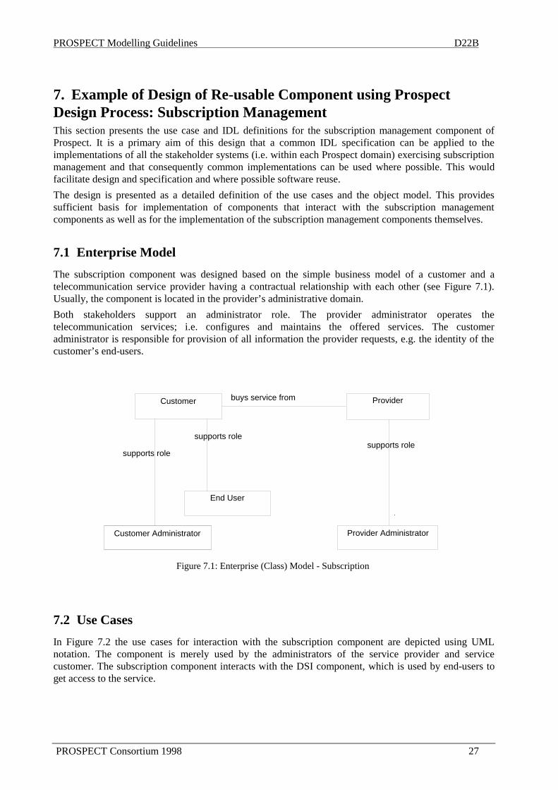
7.1 ENTERPRISE MODEL.......................................................................................................... 27
7.2 USE CASES .......................................................................................................................... 277.2.1 Subscribe Customer....................................................................................................................287.2.2 Authorise User Group.................................................................................................................28
7.3 OBJECT MODEL.................................................................................................................. 297.3.1 Subscription Contract .................................................................................................................307.3.2 Subscription Registrar ................................................................................................................31
7.4 SEQUENCE DIAGRAMS ....................................................................................................... 327.4.1 Subscribe Customer....................................................................................................................327.4.2 Authorise User Group.................................................................................................................33
8. CONCLUSIONS .......................................................................................................34
8.1 CHOICE OF NOTATION LANGUAGE AND SPECIFICATION TECHNIQUES ......................... 34
8.2 TOOL SUPPORT FOR UML ................................................................................................. 34
8.3 CONCLUSION ON DESIGN PROCESS................................................................................... 35
8.4 POSSIBLE FUTURE ENHANCEMENTS FOR THE PROSPECT DESIGN PROCESS ................. 35
GLOSSARY OF DEFINITIONS USED IN PROSPECT DESIGN PROCESS...........36
REFERENCES ...................................................................................................................40

PROSPECT Modelling Guidelines D22B
PROSPECT Consortium 1998 1
The Prospect Methodology forDesign of Multi-domain Management Services
in an Open Services Environment
1. IntroductionWith the deregulation of telecommunication network services in Europe, there is increasing interest intelecommunication services being offered by third party service providers with network services beingprovided by different telecoms operators. The benefit of such an open service environment would be inproviding the ‘one-stop-shopping’ delivery of ‘tailored’ services to end customers without thesecustomers having to deal with the multiplicity of underlying telecommunication services and networkproviders.
The difficulty with such an environment is the complexity of managing the services across the differentprovider organisations (administrative domains). The design and development of integrated, co-operativemanagement services spanning individual telecommunications service and network providers, valueadded service providers and final end users can be both complex and very time consuming.
In order to assist the design and implementation of such management services (called ‘Multi DomainManagement Services’ because they cooperate across multiple network and service providers), Prospecthas developed a design process. This design process facilitates the design and development of individualmanagement services (within a providers domain) and their co-operation and interoperation across thevalue chain of network and service providers. The design of such management systems should not ignoreexisting standard component designs. Therefore the Prospect design process facilitates the re-use ofmanagement component designs and implementations based on the TINA-C results. However themethodology itself is independent of these results.
1.1 Objectives of the Prospect Multi Domain Design Process
The objective of the Prospect System Design Process is to enable the design, development andimplementation of an integrated, coherent Multi Domain Service Management systems. This designprocess faciliates the analysis of the Prospect problem domain and supports the design andimplementation of Multi Domain Service Management systems. The Prospect design process addressesthe issues in developing end-to-end multi domain management systems. Prospect applies standardmodelling and specification techniques where applicable and developes a design process in which thesetechniques could be applied for multi domain management system development.
1.2 Overview of Document
This document first outlines the motivation for the development of a design process for describing,specifying and developing inter-domain management services. Such management services have specificrequirements since they span several administrative, technological and organisational boundaries. Thedocument then outlines the current developments in design techniques and notations and clearlyestablishes the starting point for the Prospect methodology. Chapter 4 describes a high level view of thedesign process and identifies the modelling notations adopted by the Prospect design process. In order toillustrate the application of the design process. Chapter 5 describes the design of a Multi DomainManagement Services, namely customer management. These management services cross severalorganisational boundaries in an ‘end-to-end fashion’. For example, management operations performed bythe Customer Management system (on the customer site) cause interactions with the value added serviceprovider management system (in Prospect case this is a Tele-Education Service Provider management’ssystem). These interactions, in turn, cause interactions with the Multi Media Conferencing Service

PROSPECT Modelling Guidelines D22B
2 PROSPECT Consortium 1998
Provider and Hyper Media Service Porvider management systems. Hence Customer Managementoperations cause a ‘chain’ of interactions across the various provider management systems. In order toillustrate the application of the design process, chapters 6 and 7 describe example Prospect systemdesigns developed using the design process and notations. Chapter 6 describes the Tele-EducationalService Management. . This management service has to co-operate and integrate with severalmanagement systems across administrative boundaries e.g. Virtual Private Network (Management)service. Chapter 7 describes the Subscription Management Service which is re-used in several ProspectProvider domains. Chapter 8 presents conclusions concerning the design process and its application intheProspect system. This chapter also includes the developers experience with software tools whichsupported the notations used in the Prospect design process.
2. Motivation and Requirements of a Multi Domain ServiceManagement Design ProcessThe objective of the design process is the development of Multi Domain Management Services. MultiDomain Management Services are management activities, which by necessity operate across differentmanagement administrations or organisational boundaries. Multi Domain Management Services are vitalif multiple value added service providers are to be able to manage and add value to various underlyingtele-services offered by different network or service providers, e.g. a tele-educational service providerbuilding an educational service using a Virtual Private Network from a network provider. Therefore thedesign process used to develop such management systems, must capture the interrelation and co-operationof the management services across different domains as well as supporting the development ofmanagement systems within an organisation (administrative domain).
Rather than developing new modelling techniques and notations, the design process should selectappropriate standard modelling techniques and integrate these to provide a design process for the multidomain management systems. As the Open Distributed Processing standards in telecommunications are awell established way of describing system designs from various perspectives, the design process shouldfacilitate the generation of ODP based viewpoint models for system description rather than attempting todefine design steps which interlink each viewpoint model specification explicitly. It should also facilitatethe introduction and integration of pre-existing models, designs and components into the system underconstruction e.g. TINA based component specifications.
The design process should use standard object oriented design notations for design visualisation andspecification and should support an iterative, architectural based design process. More specifically itshould comprise elements which (i) identify the stakeholders (e.g. organisations), responsibilities, rolesand activities which form the business aspect of the management service being developed (ii) providesupport for description of scenarios or ‘use cases’ (iii) provide a means of integrating pre-existingdesigns and specifications into the system model under development (iv) provide a notation for theidentification and specification of object classes, interfaces, relationships and interactions (v) provide amapping of objects into components for implementation and possible distribution (vi) support a way ofplanning, performing and executing implementation and infrastructure technology testing
2.1 Component Reuse
In the Open Service Market component reuse will occur more frequently between different organisations.There is a growing move towards the use of off-the-shelf components in the development oftelecommunication software systems as (public) network operators are outsourcing management systemdevelopment and are developing less bespoke systems [Adams-96]. The trend is toward the adoption ofindividual (packaged) systems and components, and the integration of these systems to form solution sets.This is motivated by the need to reduce costs by buying in (rather than building components from scratch)and improve quality by using reliable, robust components.
The design process should therefore cover both the development of the systems, using reusablecomponents, and the development of the reusable components themselves. These in fact should be very

PROSPECT Modelling Guidelines D22B
PROSPECT Consortium 1998 3
similar in that they will both take advantage of the same development principles, and that their concepts,notations and conventions should be similar in order that components can be easily integrated into thedesign of systems.
3. Trends in System Design for Telecommunication Network &Service Management
3.1 Tends in Object Oriented systems designThe late eighties and early nineties has seen the rise in usage of many different object oriented analysisand design techniques. Principle among the ‘second generation’ of these methodologies are Rumbaugh’sObject Modelling Technique (OMT) [Rumb-91], Ivar Jacobson’s Use-Case driven OO softwareEngineering Model [Jacob-92] and Grady Booch’s Object Oriented Analysis and Design (OOAD)methodology. Another more recent object oriented methodology has been the FUSION methodologydeveloped at HP.
The current trend in object oriented notation and distributed system specification is to harmonise existingapproaches rather than develop brand new modelling techniques. An example of this trend is the proposalof a Unified Modelling Language (version 1.0 released in March 1997). UML is a set of modellingnotations, which are independent of any software development process. It specifies the modellingnotation and the semantics underlying this notation. UML has utilised and extended modelling elementsfrom Rumbaugh’s OMT, Jacobsen’s Software Engineering Methodology and Booch’s OOADmethodologies, as well as other lesser known modelling techniques. The notations are claimed to bebackward compatible to these three principal modelling approaches [Fowl-97]. Also the ObjectManagement Group (OMG) - the consortium responsible for CORBA standards - have recently called forproposals for standard modelling notations (closing late 1997). UML itself is independent of anyparticular design process. It is envisaged that design processes will be tailored for specific applicationdomains. Therefore there is no overall ‘best’ design process because design processes for different typesof systems tend have different foci and emphasise different characteristics e.g. the design process for anoffice system would be quite different to that of a hard real-time system [UML-97].
Since Multi Domain Management Services inherently require distributed solutions, an open distributedapproach must be adopted for multi domain system description. Currently several standards address theissue of specifying open system. Principle among these is the Open Distributed Processing [ODP-94]standard that suggests the specification of five different viewpoints of the system (Enterprise,Information, Computation, Engineering and Technology). These viewpoints highlight, and provide a basisfor the separate description and discussion of, different aspects of the design and implementation of thesystem. Several standards have taken these viewpoint description concepts and enhanced them fordescribing network and service management systems e.g. TINA [TINA-93], [TINA-95] and ODMA.However, the ODP viewpoints do not provide a prescriptive design process that can be followed fordeveloping and implementing management systems [ITU-96].
The ITU-T Telecommunication Management Network recommendation [TMN-95] includes arecommendation titled ‘TMN Interface Specification Methodology’ [M3020-94] which providesguidelines for the functional decomposition of management interfaces which occur within the TMNfunctional architecture. This methodology does not provide any direct guidelines for the development ofmanagement systems internals, but rather provides a path for arriving at specifications for the interfacesproviding management functions (expressed in GDMO [X722-92]). The approach in M3020 is intendedprincipally for the specification of Standard MIBs for network elements using the CMIP networkmanagement protocol.
3.1.1 Modelling and Designing Multi Domain SystemsIn order to capture the idea that (management) services can be used independently of each other as well asbeing used in cooperation, the end-to-end management system must be viewed in two complementary(overlapping) models: (i) Inter Domain Management Model: This models the management services in co-

PROSPECT Modelling Guidelines D22B
4 PROSPECT Consortium 1998
operation to support end-to-end management services. (ii) Intra Domain Service Management Model:These models describe the management services (e.g. configuration, accounting etc.) of each of the tele-services in an Open Service Market e.g. management services for VPN, MultiMedia Conferencing,HyperMedia Services.
The reason for this decomposition is that each management service could exist on its own (i.e. is a usablemanagement service regardless of its cooperation with other services management providers). Thisreflects the view of the Open Service Market where the management of a tele-service has its ownobjectives whether or not they are infact integrated across provider organisations Thus inter domainmodels capture the end-to-end management chain while the intra domain models capture the managementservices of each individual service in isolation. However, these models are not completely independent ascomponents used for inter domain management are also used in the intra domain management.
3.2 Approaches to reuse of pre-existing components and the development ofre-usable components
Experience in Prospect and other projects related to multi domain management [Lewi-95] suggests thatrelying on only an interface definition to a component, supported by plain text descriptions for thebehaviour of the objects defining the interface, is inadequate for describing the component’s behaviour.This seems to be especially true when operations at the interface trigger interactions with furthercomponents, rather than simply providing access to internal data representations. The problems caused byhaving to rely solely on the quality of the behaviour descriptions in interface definitions can be alleviatedby accompanying documentation which indicates the dynamic behaviour of the interface with relation toother component interfaces, for instance through sequence diagrams. This reflected in the approach takenin NMF Ensembles [NMF-92].
In addition, however, the rapidly changing requirements imposed on systems by the open service marketmeans that component reuse will often involve augmentation of the component itself. However to modifya reusable component correctly and effectively, i.e. by taking advantages of its initial robust objectoriented design, the underlying design model behind the component’s interface must be accessible. ODPattempts to address this by accompanying the computational viewpoint model by an informationviewpoint model. However experience in Prospect in using TINA components seems to indicate that thisdescriptive technique is also inadequate, primarily due to the lack of a formal mapping between objects inthese two viewpoint models. In the case of Prospect, this was overcome by reverse engineering use casesfor the computational model, in order to illuminate this mapping, however this still only provided animplicit rather than explicit mapping between the two viewpoints.
The software engineering community has recognised similar problems with reuse that is based solely onclass definitions. One response to this has been to take the concept of Design Patterns from thearchitectural and construction industry and apply it to software reuse as demonstrated by Eric Gamma[Gamm-95]. Design patterns aim to try and capture the knowledge of experienced designers anddocument it in a way that facilitates the communication of architectural knowledge and of known designtraps to other developers. Typically design patterns represent common, well-proven designs. There areseveral different forms suggested for design pattern documentation, however they all follow a commonstructure. At a minimum a design pattern states a problem and outlines a solution to it, with a contextdescription that indicates the applicability of the solution. The latter part is key, since the aim is not tosell the pattern to the reader, but to provide the information needed by the reader to enable them to gaugewhether the solution presented fits well to a problem with which they are faced and satisfies any other(possibly non-functional) requirements placed upon a solution. An important feature of a pattern isgiving it a suitable, and preferably brief, name. In this way it is hoped that pattern based terminology willevolve into a more powerful means for communicating between software developers. Great emphasis isplaced on expressing patterns concisely and clearly and ideally they should also contain an example of anapplication or coding of the pattern.

PROSPECT Modelling Guidelines D22B
PROSPECT Consortium 1998 5
Design patterns are typically collected together into Catalogues [Copl-97], though more benefit can begained for the user when a collection of related patterns, possibly addressing a specific applicationdomain, are carefully cross-indexed, to show how the solutions can work together in different ways. Suchan inter-related collection of patterns is referred to as a Pattern Language.
Gamma’s original pattern catalogue addressed how small groups of software objects addressed commonproblems, however patterns have been written to address a wide range of problems up to and includingpatterns for organisational structure. Mowbray and Malveau [Mowb-97] suggest that patterns couldactually be categorised into the following levels of architectural scale:
• Global, which contains patterns that span several organisations.
• Enterprise, which contains patterns applied across a single organisation.
• System: which contains patterns concerned with the structure a system consisting of a set ofapplications.
• Application; which contains patterns addressing specific user applications.
• Macro-Architecture, which contains patterns related to application frameworks.
• Micro-Architecture, contains patterns that present object models that solve common softwareproblems (similar to Gamma’s patterns).
• Object, contains patterns for reusable objects and classes.
In the context of management system design, some parallels can be drawn between the NMF’s Ensemblesand design patterns. Both attempt to address specific problem, and both package together the problemstatement, the context and the solution. Ensembles however are aimed at solutions expressed in terms ofinteractions at a management interface, while patterns have unrestricted scope. It can be seen thereforethat by presenting Ensembles as patterns, they could become part of a wider pattern language addressingthe problems of telecommunications management system development in general. Structuring such apattern language using the levels of architectural scale described above would allow the integration ofpatterns beyond those in existing Ensembles, which would most likely be located at the application level.This would provide a framework for collecting together patterns that related not just to reuse of specificinterface specifications, but also ones which addressed both problems in constructing the systems behindthe interfaces and how these systems would fit together in a multi-provider context. Though this use ofpatterns could be useful within a provider organisation’s development effort, its application in thestandardisation and component development areas of the telecommunications management softwaresector would be novel.
For the developers of reusable components, expressing their components, and their relations to othercomponents and frameworks clearly, would benefit their customer by easing the process of selectingcomponents from a potentially wide number available. The relation of component to standards could beclarified by treating them as patterns with points of conformance, rather than simply profiles of existingstandards.
For the developers of open standards, a similar benefit would be passed to their "customers", in thatmanagement system and component developers could more readily compare and select standardisedsolutions. However it is not expected that patterns could replace standards, since the latter are still neededto provide consistent, and unambiguous definitions of interfaces. Instead, however, patterns may make theaim and application of standards more accessible than their current, necessarily complex and detailedform.
4. Prospect Multi Domain Systems Design ProcessFor the Prospect design process to be applicable to the development of systems in the Open Servicesmarket, the requirements of the different sector players, and their different resulting foci in using theprocess need to be understood. The potential users of the development process can be divided into threetypes of roles:

PROSPECT Modelling Guidelines D22B
6 PROSPECT Consortium 1998
1. Sector players interested in analysing multi-domain management scenarios and solutions. This groupincludes various standardisation bodies such as the ITU-T, ETSI, IETF, TINA-C and the NMF, as wellas industrial groupings attempting to come to an agreement on inter-working mechanisms for theirinformation systems.
2. Players responsible for developing systems for service providers, these either being the serviceproviders themselves or independent software developers subcontracted to perform these tasks.
3. Players that develop and sell general management components and management platforms for use byothers.
Figure 4.1 represents the market sectors occupied by the different role types and their relationship to eachother. The sector concerned with standardisation aims to generate industry agreement on architecturalmodels and interfaces for use in the development of systems and components. For component developersthis reduces the risk involved in developing a component. For system developers this enables easierintegration with other systems. The system developer benefits from using the components generated bythe component vendors while providing requirements both to component developers and the standardsdevelopers. The component developer also provides requirements to the standardisers.
The development process in Prospect was based on experiences where this separation of sector concernswas reflected in the working structure of the project. The project worked as a group to identify thestakeholders in its multi domain management scenarios, the management functions that would be requiredand the architecture that would be used for inter-domain interworking. Individual partners or groups werethen assigned responsibilities for developing individual provider systems, management subsystems andreusable components. The overall development methodology ensured that these different developmentstrands were consistent and the systems and components developed could then be readily integrated.
identifying common componentsand open interfaces
Standardisationarea
Component Development area
System Developmentarea
examine multi-domainissues, generate
industry agreements onopen architectures and
interfaces
develop components forreuse in multipledifferent systems
develop systems foruse in specific services
architectural guidelines
business requirements forservice systems
business requirements for commoncomponents and platforms
reusable components/platforms/ application
frameworks
requirements and feedbackon reusable components
Figure 4.1: Areas of concern in multi domain management system development

PROSPECT Modelling Guidelines D22B
PROSPECT Consortium 1998 7
4.1 Modelling notations and Methodological Techniques
Rather than developing new modelling notations or systems specification techniques, the Prospect designprocess harnesses existing modelling notations and concepts (UML) and specification languages(CORBA IDL). These notations and specification languages facilitates the description and specificationof the inter and intra domain management systems The methodology also has been influenced by themodeling work of previous ACTS projects PREPARE [Hall-96] and PRISM [Berq-96] and the TINA-CService Architecture [TINAC-94] and modelling approaches.
The design process supports each stage of development. Thus the Prospect design process iterates therequired stages of system development which includes requirements description, business modeldescription, object modelling, interface specification, implementation, deployment and testing. The ODPviewpoints provide a well-established approach to system model description. However, they do notprovide a prescriptive methodology that can be followed in developing management systems [ITU-96].Therefore unlike previous design methodologies which have attempted to specify design steps whichallow the generation of one ODP viewpoint from a previous viewpoint, the Prospect design process seesthe development of a full object oriented model as central to the overall design effort.
4.2 Overview of Prospect Design Process
The Prospect design process is concerned with the analysis, development, implementation, testing &trailing of inter and intra domain management systems. Figure 4.2 presents the design process as a cycleand identifies the different influences on the design process, the stages within the process and thespecification that can be generated during the design process. The process is iterative and all stages neednot be addressed on the first iteration of the cycle. However, in the first iteration requirements analysis(identification of stakeholders, responsibilities, use cases etc.), selecting the target architecture andplanning for integration, testing and evaluation should at least be performed.

PROSPECT Modelling Guidelines D22B
8 PROSPECT Consortium 1998
Open Service Market Influences& Service ManagementStandards/Initiatives
(Re-usableInformation
Objects & Computional
Components(e.g. TINA)
Enterprise RequirementsTechnology Constraints
Identification andSpecification of Objects and
Interaction Diagrams
Identification ofComputational Components &
Interfaces
Mapping and deployment ofComputational Components onto
infrastructure
services and management
Implementation, Integration with available
Technology and Tests
Set-up of infrastructure,
systems for the trial
MultiDomainSystemModel
Perform Trial
and Evaluate
Identification ofStakeholders/Responsibilities
Roles/ObligationsActivities/Resources
DomainsSpec. of Use Cases
Design Process
Figure 4.2: Prospect Design Process
The design process provides a structured way of developing, implementing and testing these objectdesigns. It specifies the design steps for
• developing multi domain business models (which includes the representation of stakeholders,assignment of responsibilities, identification of obligations and activities etc.),
• use case definition analysis,
• object identification and relation representation,
• definition of new computational components and the integration and extension of pre-existingcomputational components (e.g. from TINA C Service Architecture),
• distributed deployment of computational components,
• definition of platform architecture (nodes) and platform services,
• generation of test sets,
• trial execution.
The Prospect design process also identifies key places in the development process from which specificODP viewpoint models can be generated and prescribes the contents of each viewpoint modelspecification and describes how these can be generated. The information needed to generate theseviewpoint specifications is a subset of the information needed to design and implement the actualsystems. The design process ensures the consistency between each stage of the system modeldevelopment and therefore provides a means of tracing the interrelationships between the ODPviewpoints. The benefit of generating the ODP viewpoint specifications is that a clear separation of thedifferent aspects of the system can be captured. However, for the Prospect System Model Specification,such ODP viewpoint descriptions were not generated, as the Prospect designs developed during thedesign process were considered sufficient to describe and document the Prospect Systemsimplementation.

PROSPECT Modelling Guidelines D22B
PROSPECT Consortium 1998 9
4.3 Modelling/Design techniques adopted for Prospect Trial Systems
This section identifies the design techniques used in the specification of the various Prospect systems.Thus the design and specification of a Prospect system is described by the model notations listed below. Itis important to note that there is only one model of each system, however these different descriptionsallow the specific aspects and concerns to be readily presented. UML modelling notations have beenextensively used by the design process in the specification of the models.
The following design techniques and models have been used:
• Enterprise Models.
• Use Cases.
• Object Model(s).
• Sequence Diagrams.
• Definition of Components.
• Integration of Components into larger systems.
• Testing and Integration Techniques.
Design approach for Prospect re-usable components
In designing the ‘components’ to be implemented within each domain, it is important to ensure, as far aspossible, the re-use of these components. Prospect has adopted a practical approach to the development ofreusable components that has been focused on the integration of these components into the multi-domainsystems being developed. This process has involved:
• Use cases specific to the component, including ones that show interactions with other components, aswell as other systems. These can be summarised with use case diagrams.
• Component diagrams, principally showing the interfaces exported and the interfaces used by thecomponents. These interfaces should map onto, either IDL definitions or some programming languageAPI definitions.
• Sequence diagrams, again principally showing the dynamic interaction of external entities with theexternal interfaces of the component.
Approach adopted for integration and testing
These steps take place in the design process between the implementation phase and the deploymentmodel, which defines the infrastructural set up for the trial.
The different steps to be conducted during this phase were:
1. preparation of integration and tests: this step starts at the beginning of the specification as itsaim is to produce or reuse specification document(s) to support integration and tests. Thedocuments to be created during this step are defined later in this section.
2. unit tests, which tested each component in “stand alone” mode; i.e. using stub interfaces and“hard coded” components (i.e black boxes).
3. a set of integration tests that is decomposed into intermediate integration tests betweencomponents and ending by a final integration of the system.
4. a set of acceptance tests, these tests are in relation with the Trial and are based on the usecases.

PROSPECT Modelling Guidelines D22B
10 PROSPECT Consortium 1998
4.4 Specification techniques adopted for description and documentation ofProspect Trial Systems
The Prospect project is a ‘trial based project’ which means that one of the primary goals of the projectwas the trialling of multi domain management systems. Therefore Prospect applied the design process tosupport the following objectives:
• To support the development of systems, built largely from reusable components, that satisfy thespecific goals of individual project trials.
• To support the evolution of common reusable components across the lifetime of the project (andpossibly beyond).
The development of the trial systems involved the development of the models and descriptions listedbelow, during different stages in the development process. Figure 4.3 illustrates the stages, during thedesign process, where these descriptions were developed.
1. A trial enterprise model, identifying the stakeholders and roles involved in the trial. These are used asthe basis for developing functional requirements.
2. A set of trial system level use cases, defining the overall aims of the trial system in terms of userinteractions with the trial systems
3. A breakdown of the trial system level use cases onto requirements on the components and systems thatmake up the trial system.
4. A system architecture showing how the trial system is composed of individual components, systemsand subsystems
5. A set of acceptance tests defining the interactions that need to be conducted to show that the full usecases can be conducted by the final system.
6. A set of integration tests that define intermediate integration tests between components. This shouldinclude references to inter-partner integration tests that are required between separately implementedparts of the component.
7. A deployment model showing how the trial system will be deployed for the trial itself.
Figure 4.3 Elements of Trial System Descriptions
.A system architecture showing
how the trial system is composed of individualcomponents, systems and subsystems
A Deployment Model showing how the trial system
will be deployed for the Trial itself.
Open Service Market Influences& Service Management Standards/Initiatives
Multi
Domain
System
Model
• An trial enterprise model, identifying the stakeholders and roles
involved in the trial • A set of trial system level use cases,
defining the overall aims of the in terms of user interactions
with the trial systems
Design Process
(Re-usable
Information
Objects
& Computional
Components(e.g. TINA)
A breakdown of thetrial system level use cases ontorequirements on the components
and systems that make upthe trial system
Enterprise Requirements
Technology Constraints
A set of integration tests that define intermediate integration
tests between components. Include references to inter-partner integration tests that
are required within a component
A set of acceptance tests defining the interactions that need to be
conducted to show that the full use cases can be conducted
by the final system.

PROSPECT Modelling Guidelines D22B
PROSPECT Consortium 1998 11
Description of re-usable components
In addition to these parts, which represent points required along the development path of the trial,additional documentation is required for each of the reusable components that are to be used in the trial.In these trials the evaluation of alternative reusable components has not been a major activity, since thecomponents used where simply those available and few others were considered.
As most of these components are pre-designed to a large extent (from sources such as TINA), it was notfeasible, or indeed necessary, to re-document all their development stages in the same manner as for thetrial systems. However the component documentation needed to provide the following in order tofacilitate the integration of the components into the system design:
• A set of generic use cases for the component. It should then be possible to map the requirements of thetrial systems and individual stakeholder systems to these use cases to ensure that the componentsatisfies the requirements of these systems.
• A description of the component in terms of the interfaces it exports, which may be protocol interfaces,IDL interfaces or some other form of API-like interface. This component level description should alsoindicate which other components this component depends upon. These component descriptions maythen be used in the system architecture models for the overall trial systems.
• A set of acceptance tests, traceable to the component use cases, that could be reused if necessary asparts of trial system acceptance tests.
The documentation was based as much as possible on the use of UML, using both Paradigm Plus andRational Rose CASE tools.
Documentation of integration and tests
These steps are supported by a set of documents:
• Scenarios or test suites, defined from the use cases, that are used for the acceptance tests.
• Sequence diagrams, which is the base document for integration tests as it defines theinteractions between components with defined parameters and values to be returned.
• Error cases which describe the exceptions to be returned in some situations.
• Naming conventions which allows the definition of constraints to be applied on specificparameters values. This has been found useful during integration tests.
Tools can be used during integration and testing stage of the design process, e.g. a common database forreporting defects.
4.5 Generating ODP Viewpoint Descriptions
It is not anticipated that ODP viewpoint specifications need always be generated but some managementsystem developers may desire to use such ODP specifications to describe and compare their systems toexternal developers/managers. In order to facilitate the generation of such viewpoints, key elements of themodels produced by the design process can be combined to serve as a basis from which Enterprise,Information and Computational ODP viewpoint models can be generated. The information needed togenerate the ODP viewpoint specifications are a subset of the information needed to design andimplement the actual systems. Thus the contents of each viewpoint model specification can be prescribedand generated from the elements of the system model.

PROSPECT Modelling Guidelines D22B
12 PROSPECT Consortium 1998
Stage in Design Process from which Viewpoint is derived ODP Viewpoint
Textual description of:
- Stakeholders, Relationships, Roles, Obligations, Activities
UML Class Diagram Notation diagrams used to represent the stakeholdersand the relationships between them
UML Use Case Notation (text based descriptions of user interactions)describing required operations/activities
Enterprise Model
UML Class & Object Model Diagrams, UML Interaction Diagrams (bothsequence diagrams and Collaboration Diagrams) e.g. class, aggregation,etc.
Specification of Class interfaces
Information Model
UML Component Model using IDL specification of component interfaces Computational Model
UML Implementation Diagrams (showing components and deployment) Engineering Model
Table 1 Mapping from elements of inter and intra domain models to ODP viewpoint models
In fact the ODP viewpoints descriptions (Enterprise, Information, Computation) were used in the earlystages of the project but were not infact all needed in the final system description provided by the project[D4B-98].
5. Example of Multi-Domain System Analysis: CustomerManagement TrialThe target multi domain systems developed in Prospect are those used for performing user trials withinthe project. These trial systems were required to demonstrate the interactions of service and managementsystems between a number of organisations. The example presented here concentrates on the CustomerManagement Trial System developed in Prospect. The Prospect trial aims to demonstrate the design andimplementation of management systems where ‘chains’ of interactions across the various providermanagement systems are required to deliver ‘end-to-end’ service management.
5.1 Enterprise Model
For each trial an enterprise model is required so that the inter-domain interactions can later be clearlyidentified, and so that the various functions provided by each organisation’s system in the trial can beassessed in line with the organisations business objectives, e.g. providing a Tele-Education Service (TES)to a customer, or reselling multimedia services to the TES provider.
Enterprise models were expressed as object diagrams, where the objects were instantiations of thefollowing stakeholder and role classes:
• composite provider class: a stakeholder providing a service composed of services provided by otherservice providers.
• multimedia teleservice provider stakeholder.
• value added service provider stakeholder.
• network operator stakeholder.
• provider administrator role.
• customer administrator role.

PROSPECT Modelling Guidelines D22B
PROSPECT Consortium 1998 13
• end user role.
The relationship between these classes are shown in Figure 5.1 below. This set of classes was intended tocover the range of roles found in the various Prospect trials, however they are fairly general and may beextended to cover other enterprise situations related to telecommunications-based services.
compositeserviceprovider
multimediateleserviceprovider
valueaddedserviceprovider
networkoperator
customer
end usercustomeradministrator
provideradministrator
providerbuys services from1..*0..*
supports role
0..*
1
supports role
0..*
1supports role
*
1
Figure 5.1 Prospect Trial 2 Enterprise (Class) Modell
The enterprise model for a trial details the different organisations and user roles that were relevant to theoverall trial system and the relationships between them. This was represented as a UML object diagramcontaining instances of the enterprise model classes defined for the project as a whole. The objectdiagram for the Customer Management Trial is show in Figure 5.2.
To provide a more detailed context for the definition of use cases, the exact state of the relationshipbetween the roles and organisations prior to the trial is defined in the enterprise model. This take the formof statements of contractual relationships between the different stakeholders. Note that other relationshipsmay be developed as part of the trial itself and the instantiation of such a relationship would therefore bethe subject of one of the trial system use cases.

PROSPECT Modelling Guidelines D22B
14 PROSPECT Consortium 1998
TES Provider :composite
serviceprovider
TESCustomer :customer
TES CustomerAdministrator :
customeradministrator
HM Provider :multimediateleserviceprovider
WS Provider :multimediateleservice
provider
TES ProviderAdministrator
provideradministrator
MMC Provider: multimediateleservice
provider
TES EndUser :
end user
has contract with
uses mgmt services
uses mgmt services
uses mgmt services
uses mgmt services
uses mgmt services
uses services
uses services
uses services
Figure 5.2: Customer Management Trial Enterprise Model
5.2 Use Cases
Trial system use cases express the user interactions which the trial should be demonstrating, thusproviding the basis not only for the analysis and design of these systems that implement these use cases,but also the basis for the evaluation of the trial. These top level use cases are therefore stated in terms ofthe trial system as a whole and its interaction with actors that represent the users or evaluators of the trialitself.
The high-level use cases may be accompanied by an overview of how the use case will generate inter-domain information flows in order to help people understand the extent of the design impact of aparticular use case, and should not be considered part of the use case itself.
UML use case notation can be used to summarise the relation between the use cases, and between the usecases and the actors involved. Individual use cases should however be defined separately giving thetextual description of the use case, the preconditions assumed for the use case and possibly any specificopen issues concerning existing designs raised by this use case.
The set of use cases and the details of those use cases changed over the development process, with factorsfrom the later design and implementation stages always being fed back to the use cases so that theyproperly represented the functionality of the system. The use cases were summarised using UML asshown in Figure 5.3.

PROSPECT Modelling Guidelines D22B
PROSPECT Consortium 1998 15
T21a system
TES CustomerAdministrator
TES ProvidAdministra
TES EndUser
createstudent
SAG
assignstudentSAG tostudentprofile
authorise astudent
bar astudent
usecourseservice
accessTES
service
generate bill
Figure 5.3: Use Case diagram summarising the Customer Management Trial system functionality
The use cases themselves were defined in plain text with a set of pre-conditions that aided in defining thesequence of use cases in relation to each other. Two examples from the set above are given below.
5.2.1 Use Case: Accesses TES ServicePreconditions:The customer organisation has an account with the TES provider.The customer is subscribed to certain services.The user is authorised to use the service he/she is trying to access.
Use case description:The user accesses the TES WWW site via a WWW-browser. On clicking on the link to access TESservices the user is presented with a dialogue box in which he/she must enter a user ID and a PINpreviously supplied by the TES provider. If the user enters an invalid user ID and/or PIN he/she isinformed that their access has been denied. Otherwise the user is presented with a list of zero or moreavailable services that he/she may access. The user may then select one of these services or opt to selectnone of them. If a service is selected further service specific interactions are then enabled. In addition theuser will be presented with a way to exit the TES service that he/she has selected at any time.

PROSPECT Modelling Guidelines D22B
16 PROSPECT Consortium 1998
5.2.2 Use Case: TES Customer Administrator sets up specific SAG intended for TES endusers
Preconditions:The customer already has an account with the TES provider.The customer administrator is authorised to use the TES customer management service.The customer is subscribed to the service the end user wishes to useUse Case:The TES Customer Administrator accesses the TES customer management service.The Customer Administrator requests to create a new subscription assignment group, supplying the nameof the group, the maximum size of the group and a description of the group. On successful completion ofthe operation a confirmatory message is provided to the customer administrator. The operation will fail ifthe name of the SAG already exists.
5.2.3 Use Case BreakdownOnce the overall functionality of the trial system had been defined by these use cases, the functionalityhad to be decomposed, both into that needed by systems operated by the different organisations in thetrial and the functionality needed from the reusable components. The identification of which reusablecomponents would be used in which organisational domains had largely be defined earlier in the projectsince the aim of the trial was partially to show this reuse of components. The detailed breakdown stillneeded to be recorded however and this was done in the context of each of the overall trial system usecases.
This breakdown was attempted using use cases and sequence diagrams. In the use case approach, theindividual use cases were broken down into use cases related to individual systems and components andtheir relationship shown using UML use case diagrams. This therefore defined use cases for theindividual organisations’ systems, and used the use cases that had been defined for the components.Examples for the two uses cases given above as provided in Figure 5.4 and 5.5.
T21a system
TES CustomerAdministrator
TES ProvidAdministra
TES EndUser
createstudent
SAG
assignstudentSAG tostudentprofile
authorise astudent
bar astudent
usecourseservice
accessTES
service
DSI component
accessservices
useservice
extends
uses
uses
generate bill
uses
uses
uses
uses
uses
Figure 5.4: Breakdown of Access TES service use case

PROSPECT Modelling Guidelines D22B
PROSPECT Consortium 1998 17
TES systems
core subscription component
MMTS system
TES CustomerAdministrator
createstudent
SAG
core subscription component
createSAG
createSAG
createMMTS
user SAG
extends
uses
uses
Figure 5.5: Breakdown of create student SAG use case
The sequence diagram approach used sequence diagrams that contained the various organisation systemsand the components of which they were composed, and for specific use cases showed the resultingsequences of interactions between them.
Figure 5.6 below provides a summary of a subset of the primary use cases used in the CustomerManagment Trial and how they map onto the different provider systems. (A single diagram consisting ofall use cases in Customer Management Trial would be too complex to be of value).

PROSPECT Modelling Guidelines D22B
18 PROSPECT Consortium 1998
TES CustomerAdministrator TES Provider
Administrator
TES Provider System
authorise astudent
TES Customer Administrator System TES ProviderAdministror System
HM Provider System MMC Provider System WS Provider System
TES End User System
TES EndUser
authorise astudent
bar astudent
bar astudent
generate bill
authoriseuser
authoriseuser
authoriseuser
bar user bar user bar user
generate bill
get bill get bill get bill
accessHM
service
accessMMC
service
accessWS
servcie
use HMservice
use MMCservice
use WSservice
accessTES
service
usecourseservice
extendsextends
extendsextends
extendsextends
extends
extends
extendsextends
extends
extends extends
extends
extends
extends extends extends
Figure 5.6: Customer Management Trial inter-domain use case summary
5.3 System Architecture
In the context of a multi-domain system in a commercial service provision situation, the multi-domaindevelopment process is unlikely to proceed to a stage involving detailed design, implementation andtesting, this typically being left to the individual stakeholders involved. Instead, such a multi domainsystem development process is envisaged as a tool for use by those involved in arriving at industryagreements on the interfaces and process involved in open, inter domain management activities. Thedevelopment process will principally be one of analysis and high level design on the multi-domainenterprise model and use case specification. Further refinement of the overall design occurs during thedesign of the different constituent domains or during the design of the reusable components. The ultimatebenefit to industry of such analyses is common specification for software components that supportmanagement specific activities across several domains. The approach demonstrated in the previoussection, where multi domain use cases are decomposed into use cases for specific components provides uswith a means of identifying and specifying such components. The identification of reusable components,developed in Prospect for the systems involved in the Customer Management Trial, is therefore the mainarchitectural result of the analysis process conducted at this multi domain level. This is represented inFigure 5.7 below.

PROSPECT Modelling Guidelines D22B
PROSPECT Consortium 1998 19
Desktop/serviceIntegration
TES ProviderSystem
TES End UserSystem
provider domainsession control
accountingmanagement
subscriptionmanagement
user domain sessioncontrol
WS ProviderSystem
HM ProviderSystem
TES ProviderAdministror
System
MMC ProviderSystem
TES CustomerAdministrator
System
Figure 5.7: Use of reusable components in Customer Management Trial systems
6. Example Design of Inter Domain System using Prospect DesignProcess: Tele-education Service ManagementThe Prospect tele-education service provides educational courses to interested customers and is composedof a number of telecommunication services. Both information services like the Hypermedia Service andCommunication Services like the Virtual Private Network Service (VPN) are integrated. The TESmanagement system therefore has to co-operate with management systems of the subcontractors, acrossadministrative boundaries. This is the major requirement imposed on the design of the managementsystem.
Interworking between systems in different administrative domains is facilitated by re-use of softwarecomponents in the systems. Therefore, implementations and specifications of the Prospect componentswere re-used where possible. As in Section 5, the design is presented as a detailed definition of the usecases and the object model.

PROSPECT Modelling Guidelines D22B
20 PROSPECT Consortium 1998
6.1 Enterprise Model
The TES management system was developed based on the enterprise model depicted in Figure 6.1. Thecustomer buys a tele-education service from the TES provider for students belonging to theirorganisation. Since this service is composed of several multimedia tele-services (TS), e.g. multimediaconferencing and WebStore, the TES provider in turn buys these services from the correspondingprovider. All stakeholders support an administrator role, but only the TES customer and the TES provideradministrator can use the TES management service.
TES Customer Administrator
supports role
Student
supports role
buys service fromTES Customer
TES Provider Administrator
supports role
TES Provider buys service from TS Provider
TS Provider Administrator
supports role
Figure 6.1: Enterprise Model - TES Management
6.2 Use Cases
Figure 6.2 shows the use cases defined for interaction with the TES management system. Two types ofactors are supported; administrators of TES customers and of the TES provider. The TES provideradministrator can act on behalf of a customer; i.e. all the use cases performed by the customeradministrator can also be performed by the provider administrator.
The TES management use cases were derived from use cases defined for the subscription and theaccounting component. The first of the scenarios described below was derived from a subscription usecase, the second one from an accounting use case.

PROSPECT Modelling Guidelines D22B
PROSPECT Consortium 1998 21
Create TES Customer Delete TES CustomerCreate Service Delete Service
Authorise TES User Group
Bar TES User Group
Add TES User Add Customer SiteBar TES User Remove Customer Site
Create TES User Group
Delete TES User Group
Modify Customer Details
Modify Subscription Details
TES ProviderAdministrator
Get Total Bill
Subscribe TES Customer Unsubscribe TES Customer
TES CustomerAdministrator
Get Customer Bill
Figure 6.2: TES Management Use Cases
6.2.1 Subscribe TES CustomerPreconditions:
The TES management system is initialised. A service and the account of the customer have already beencreated. The administrator has access to a management application or service that is able to connect to theTES management system.
Use Case Description:
The administrator selects the service the customer wants to subscribe to. Further details of thesubscription are defined, e.g. service profiles, tariffs.
Postconditions:
The customer is subscribed to the service and a subscription contract is concluded.
6.2.2 Get Customer BillPreconditions:
The TES management system is initialised. The customer is subscribed to a service. The administratorhas access to a management application or service that is able to connect to the TES management system.
Use Case Description:
The administrator receives the bill for usage of the services the customer is subscribed to.
Postconditions:

PROSPECT Modelling Guidelines D22B
22 PROSPECT Consortium 1998
The bill is displayed.
6.3 Object Model
The TES management system is composed of three adapted Prospect components; subscription,accounting, and session control (DSI). In Figure 6.3 the architecture of the management system isdepicted.
Two different actors, namely the customer operator and the provider operator, can access the system byusing a special management application that connects to the management service of the TES provider.That means, the TES management service is an extra service type available for all TES customers and forthe TES provider.
TES SubAgt<<CO>>
TES ChgCtrl<<CO>>
TES UMLog<<CO>>
uses
uses
CusOp MgmtAppl<<System>> uses
Customer Operator
usesCusOp UserAgent
<<CO>>
controls
TES SubMgr<<CO>>
TES SubRgs<<CO>>
TES ConfMgr<<CO>>
CusOp UserSessionManger<<CO>>
uses
controls
Mgmt ServiceFactory<<CO>>
TES STH<<CO>>
TES BillCtrl<<CO>>
TES UMData<<CO>>
TES SubMgrProp<<CO>>
TES SubRgsProp<<CO>>
TES TariffCtrl<<CO>>
ProvOp UserAgent<<CO>>
uses
ProvOp UserSessionManager<<CO>>
uses
ProvOp MgmtAppl<<System>>uses
Provider Operator
<<Component>>Session Control
<<Component>>Accounting
<<Component>>Subscription
Figure 6.3: TES Management Design

PROSPECT Modelling Guidelines D22B
PROSPECT Consortium 1998 23
Adaptation of the components was done in different ways. While only the DSI design and the accountingspecifications were reused, an implementation of the subscription component was integrated with thesystem.
The overall DSI design and the specifications of user agent (UA) and service factory (SF) CO werereused. User session manager CO (USM) specifications for both customer and provider operators havebeen developed, based on the definition of the envisaged use cases. The specification of the accountingobjects was reused, too. Propagation of accounting information from TES subcontractors is alreadysupported by the component design.
Since it was planned to reuse an implementation of the subscription component, a number of additions tothe component design were necessary. For instance, propagation of customer information to the TESsubcontractors is not supported by the current implementation. Therefore, two TES specific COs havebeen specified in order to perform this task. The subscriber manager propagator CO (SMP) is responsiblefor forwarding the SAG management requests to the corresponding subscriber manager COs of thesubcontractors. The subscription registrar propagator CO (SRP) forwards subscription requests to thesubcontractors’ subscription registrar COs. Both COs inherit interfaces from the corresponding COs ofthe subscription component, the subscriber manager and the subscription registrar CO.
Another TES specific CO is responsible for forwarding the requests to the VPN provider. Theconfiguration manager CO (CM) is notified by the SRP whenever re-configuration of the networkconnections is needed, e.g. if a customer adds a new site to the list of access points available for their end-users.
In the following, two of the TES-specific COs are described briefly; the subscription registrar propagatorCO and the customer management USM CO.
6.3.1 Subscription Registrar Propagator
i_srpPrpgnMgmt
setSvcTmpltMapping( )setSvcProfileMapping( )delSvcTmpltMapping( )delSvcProfileMapping( )
i_srpPrpgnInfoQuery
getSvcTmpltMapping( )getSvcProfileMapping( )
i_srpSubscrnMgmt i_srpSubscrnCntrl
i_CoInit
init( )terminate( )
(from Interface)
i_CoMgmt
setAdminState( )getAdminState( )
(from Interface)
i_srpInit
i_srpMgmt
i_subscrnMgmt
subscribe( )cancel( )activate( )deactivate( )modifySubscriptionContract( )
(from Subscription Registrar)
i_subscrnControl
setSubscription( )assign( )deassign( )setSvcProfile( )delSvcProfile( )getSubscriptionContract( )
(from Subscription Registrar)
Figure 6.4 Subscription Registration

PROSPECT Modelling Guidelines D22B
24 PROSPECT Consortium 1998
The subscription registration propagator CO (SRP) acts on behalf of the service provider in dealing withsubscribers wishing to subscribe to a service. The SRP forwards requests to the local SubRgs CO and ifnecessary to SubRgs in subcontracted provider domains. It is responsible for the mapping of a servicetemplate to those used in the subcontractor domains and for the mapping of service profiles to thoseprovided by its subcontractors.
The SRP CO maintains the following information:
• the mapping of service templates.
• the mapping of service profiles.
One SRP operates in the service provider domain. The CO provides the following interfaces:
• Object Lifecycle Management Interface (i_srpInit): This interface provides operations for initialisingand terminating this object.
• Object Management Interface (i_srpMgmt): This interface provides operations for controlling theadministrative state of the CO.
• Subscription Management Interface (i_srpSubscrnMgmt): This interface provides operations for set-up and modification of service subscriptions. It inherits from the interface i_subscrnMgmt of theSubRgs.
• Subscription Control Interface (i_srpSubscrnCtrl): This interface provides operations for set-up andmodification of service profiles. It inherits from the interface i_subscrnControl of the SubRgs.
• Propagation Management Interface (i_srpPrpgnMgmt): This interface allows the provider operator tomanage service profile mappings.
• Propagation Information Query Interface (i_srpPrpgnInfoQuery): This interface provides theprovider operator with information about service template mappings and service profile mappings.
6.3.2 Customer Operator User Session Manager
i_usmSci
initiate( )terminate( )
(from User Session Manager)
i_usmLci
initialise( )remove( )
(from User Session Manager)
i_CMUsmInfoQuery
get_service_list( )get_service_template( )get_subscription_contract( )get_subscription( )get_subscriber( )get_subscription_portfolio( )get_SAG_list( )get_SAG( )get_assigned_SAG_list( )get_svc_profile( )get_svc_profile_id_list( )get_profile_info( )list_tariffs( )get_tariff( )
i_CMUsmSubMgmt
subscribe( )cancel_subscription( )set_subscription( )modify_subscriber_details( )modify_subscription_contract( )
i_CMUsmSagMgmt
define_SAG( )modify_SAG( )add_SAG_item( )remove_SAG_item( )delete_SAG( )
i_CMUsmSvcMgmt
assign_SAG( )deassign_SAG( )
i_CMUsmAccMgmt
get_bill( )
Figure 6.5 User Session Manager

PROSPECT Modelling Guidelines D22B
PROSPECT Consortium 1998 25
The customer management USM (CMUSM) consists of a number of interfaces which provide thenecessary management functionality for TES customers, e.g. subscription and SAG management. TheCMUSM is (TES) service independent and one operates per customer operator.
The CMUSM CO provides the following interfaces:
• Life-cycle Management Interface (i_usmLci): This interface provides operations for initialisation anddeletion of the object.
• Session Control Interface (i_usmSci): This interface provides operations for initiating andterminating end-user sessions.
• Information Query Interface (i_CMUsmInfoQuery): This interface provides the customer operatorwith information about services, subscriptions, SAGs, and profiles.
• Subscription Management Interface (i_CMUsmSubMgmt): This interface allows the customer tosubscribe to services.
• Subscription Assignment Group Management Interface (i_CMUsmSagMgmt): This interface allowsthe customer operator to manage user groups.
• Service Management Interface (i_CMUsmSvcMgmt): This interface provides operations to managethe assignment of user groups to service profiles.
• Accounting Management Interface (i_CMUsmAccMgmt): This interface provides operations to getaccounting details.
6.4 Sequence Diagrams
In the following subsections sequence diagrams are presented that illustrate the object interactions for theuse cases defined in Section 6.2.
6.4.1 Subscribe TES CustomerPreconditions:
The TES management system is initialised. The customer and the service IOs are initialised. Either thecustomer or the provider operator have initialised the management application and have access to the TESmanagement service.
Sequence:
CUAP : ManagementApplication
CUSM : i_CMUsmSubMgmt
SRP : i_srpSubscrnMgmt
SRGS : i_subscrnMgmt
1: subscribe (in t_SubscriptionContract)
2: subscribe (in t_AccountNo, in t_SubscriptionContract)
CustomerMgmt USM
Subscription Registrar Propagator
3: subscribe (in t_AccountNo, in t_SubscriptionContract)
Subscription Registrar
Figure 6.6 Subscribe TES Customer

PROSPECT Modelling Guidelines D22B
26 PROSPECT Consortium 1998
1. The customer operator selects the service he wants to subscribe to and invokes the subscribeoperation at the USM.
2. The USM forwards the request to the subscription registrar propagator CO.
3. The SRP forwards the request to the local subscription registrar CO.
6.4.2 Get Customer BillPreconditions:
The TES management system is initialised. The customer is subscribed to the service. Either the customeror the provider operator have initialised the management application and have access to the TESmanagement service.
Sequence:
CUAP : ManagementApplication
USM : i_CMUsmAccMgmt
BCTRL : i_billControlMgmt
1: get_bill (in t_DateTime, in t_DateTime, out t_Bill)
2: getBill (in t_AccountNo, in t_DateTime, in t_DateTime, out t_Bill)
Customer Mgmt USM Bill Control
Figure 6.7 Get Customer Bill
1. The operator invokes the get_bill operation at the USM.
2. The USM forwards the request to the local bill control CO.
PROSPECT Modelling Guidelines D22B
PROSPECT Consortium 1998 27
7. Example of Design of Re-usable Component using ProspectDesign Process: Subscription ManagementThis section presents the use case and IDL definitions for the subscription management component ofProspect. It is a primary aim of this design that a common IDL specification can be applied to theimplementations of all the stakeholder systems (i.e. within each Prospect domain) exercising subscriptionmanagement and that consequently common implementations can be used where possible. This wouldfacilitate design and specification and where possible software reuse.
The design is presented as a detailed definition of the use cases and the object model. This providessufficient basis for implementation of components that interact with the subscription managementcomponents as well as for the implementation of the subscription management components themselves.
7.1 Enterprise Model
The subscription component was designed based on the simple business model of a customer and atelecommunication service provider having a contractual relationship with each other (see Figure 7.1).Usually, the component is located in the provider’s administrative domain.
Both stakeholders support an administrator role. The provider administrator operates thetelecommunication services; i.e. configures and maintains the offered services. The customeradministrator is responsible for provision of all information the provider requests, e.g. the identity of thecustomer’s end-users.
Customer Administrator
supports role
End User
supports role
buys service fromCustomer
Provider Administrator
supports role
Provider
Figure 7.1: Enterprise (Class) Model - Subscription
7.2 Use Cases
In Figure 7.2 the use cases for interaction with the subscription component are depicted using UMLnotation. The component is merely used by the administrators of the service provider and servicecustomer. The subscription component interacts with the DSI component, which is used by end-users toget access to the service.

PROSPECT Modelling Guidelines D22B
28 PROSPECT Consortium 1998
DSI Component
create service
delete service
subscribe customer
unsubscribe customer
create customer
delete customer
authorise user group
bar user group
create user group
delete user group
Administrator
Figure 7.2: Subscription Use Cases
The following two subsections illustrate the definition of use cases in plain text. In the first use case, acustomer is subscribed to a service. In the second one, the customer authorises a group of end-users toaccess a subscribed service.
7.2.1 Subscribe CustomerPreconditions:
The subscription component is initialised. The service and an account for the customer have already beencreated. The administrator has access to a management application, which is able to connect to thesubscription component.
Use case description:
The administrator selects the service the customer wants to subscribe to. Further details of thesubscription are defined, e.g. service profiles, tariffs.
Postconditions:
The customer is subscribed to the service and a subscription contract is concluded.
7.2.2 Authorise User GroupPreconditions:
The subscription component is initialised. The service and an account for the customer have already beencreated. The customer is subscribed to that service and a user group has been created. The administratorhas access to a management application, which is able to connect to the subscription component.
Use case description:
The administrator assigns the user group to the service subscription.

PROSPECT Modelling Guidelines D22B
PROSPECT Consortium 1998 29
Postconditions:
The end-users of the user group are able to access and use the service.
7.3 Object Model
The subscription component should support for subscribers to allow end-users to access services. Thesubscription COs therefore define generic capabilities needed to manage, from the subscription point ofview, different types of services. The COs related to subscription include (see Figure 7.3):
• Service template handler,
• Subscriber manager,
• Subscription registrar, and
• Subscription agent.
The service template handler is responsible for handling service templates that represent servicecapabilities provided by the provider. It also provides operations, such as verification of subscriptionparameters, to the corresponding subscription registrar. The subscriber manager manages informationassociated to subscribers, e.g. subscriber details and user groups.
1..*
uses
1..*
ServiceOperator
1..1
uses
1..*
0..*
controls lifecycle of
1..1
0..*
Subscriber<<IO>>
controls
1..1
0..*
UserGroup<<IO>>
controls
1..1
1..1
controls lifecycle of
1..1
UserAgent<<CO>>
1..1
uses
1..*
0..*
ServiceTemplate<<IO>>
controls
1..1
0..*
uses
1..*
ManagementApplication<<System>>
1..*
1..*
1..1SubscriberManager
<<CO>>
1..1
1..*
0..*
1..1
0..*
1..1
0..*
1..1
uses
0..*
0..*SubscriptionAgent
<<CO>>
1..1
1..1
notifies
0..*
1..1ServiceTemplateHandler
<<CO>>
1..1
1..*
0..*
1..1
uses
0..*0..*
SubscriptionContract<<IO>>
controls
1..1SubscriptionRegistrar
<<CO>>
0..*
1..*
1..1
0..*
0..*0..*
1..1
0..*0..*
1..1
Figure 7.3: Design of the Subscription Component
The subscription registrar acts on behalf of a provider in dealing with subscribers wishing to subscribe toa service. A single subscription registrar can collect information for one service from one or moresubscribers and will handle exactly one service, since each service is likely to have different requirements

PROSPECT Modelling Guidelines D22B
30 PROSPECT Consortium 1998
for subscribing a customer to a service. A subscription registrar is responsible for managing ofsubscription contracts, among others.
The subscription agent is closely related to the user agent CO that belongs to the DSI component. It sendsappropriate subscription information to the user agent, in reply to its request. The subscription componentis accessed by a management application. Separate applications may be developed for customer andprovider administrators.
In the following two subsections the specification of the subscription contract IO and the interfaces of thesubscription registrar CO are presented. The interfaces should correspond with those used for theCORBA interfaces making up the corresponding engineering object.
7.3.1 Subscription Contract
t_SvcId
(from Service Types)
1..1
1..1
svc_id
t_SubscriptionContract
1..1
1..1
1..1
1..1
userPlan
1..1
1..1
requested_start basicTariff
1..1
1..1
actual_start
billing_contact_pt
1..1
1..1
tech_contact_pt
1..1
1..1
1..1
1..1
requested_by
t_Person
name : stringaddress : stringtel_no : string
(from Service Types)t_DateTime
(from Types)
t_TariffId
(from Tariff)
Figure 7.4 Subscription Contract
A subscription contract comprises all details of the subscriber to provider relation. The IOt_SubscriptionContract contains the following information:
• Service Identifier (t_SvcId): This is an unique identifier for the service.
• Requestor (t_Person): This is the person in the customer domain who requested the subscriptioncontract.
• Billing Contact (t_Person): This is the person in the customer domain responsible for payment of thebill.
• Technical Contact (t_Person): This is the technical contact person in the customer domain.
• Requested Start (t_DateTime): This is the requested start date and time.
• Actual Start (t_DateTime): This is the actual start date and time.
• Basic Tariff (t_TariffId): This is an unique identifier for the basic tariff the subscriber has to pay.
• User Plan (t_TariffId): This is a unique identifier for a special tariff for a subscriber, e.g. a discount.

PROSPECT Modelling Guidelines D22B
PROSPECT Consortium 1998 31
7.3.2 Subscription Registrar
i_subscrnMgmt
subscribe( )cancel( )activate( )deactivate( )modifySubscriptionContract( )
i_subscrnInfoQuery
getSubscription( )checkConfig( )getUsersSubscriber( )getSvcProfile( )getProfileIdList( )getSLA( )
i_subscrnControl
setSubscription( )assign( )deassign( )setSvcProfile( )delSvcProfile( )getSubscriptionContract( )
i_CoInit
init( )terminate( )
(from Interface)
i_CoMgmt
setAdminState( )getAdminState( )
(from Interface)i_srInit i_srMgmt
Figure 7.5 Subscription Registrar
The subscription registrar (SubRgs) CO acts on behalf of the service provider in dealing with subscriberswishing to subscribe to a service. The subscription registrar activates subscriptions to a service, collectingsubscription information from administrators and logging/modifying subscription information. A singleSubRgs is responsible for exactly one service, since each service has different requirements forsubscription and authorisation. The CO also authorises subscription assignment groups.
The SubRgs is service dependent. One SubRgs exists in each service provider domain for each separateservice (as defined by a service template) that is offered by that provider. The behaviour of the SubRgsmay vary depending on the operational semantics of the service it supports.
The subscription registrar CO maintains the following information:
• Subscription contracts
• Subscriptions, including profiling information affecting all subscription assignment group IOs (SAG)operating under this subscription
• Service profiles
• SAGs that have service profiles assigned to them
• The relationships between service profiles and SAGs for different subscriptions.
The Subscription Registrar CO provides the following interfaces:
• Object Lifecycle Management Interface (i_srInit): This provides operations for initialising andterminating this object.
• Object Management Interface (i_srMgmt): This provides operations for controlling the administrativestate of the CO.
• Subscription Management Interface (i_subscrnMgmt): This interface allows for the set-up andsubsequent modification of service subscriptions.

PROSPECT Modelling Guidelines D22B
32 PROSPECT Consortium 1998
• Subscription Control Interface (i_subscrnControl): This provides operations for controlling thesubscription of customers to the service by manipulating subscription contracts and service profiles.
• Subscription Information Query Interface (i_subscrnInfoQuery): This provides operations forobtaining information about subscription contracts and service profiles. This interface is available tothe service customer.
7.4 Sequence Diagrams
The sequence diagrams presented below illustrate the object interactions for the use cases introduced inSection 7.2.
7.4.1 Subscribe Customer
MUAP : ManagementApplication
SRGS1 : i_subscrnMgmt
SRGS2 : i_subscrnControl
SMGR1 : i_sbrInfoQuery
SMGR2 : i_subscrnNotify
STH : i_subscrnVerify
1: subscribe (in t_AccountNo, in t_SubscriptionContract)
2: getSubscriber (in t_AccountNo, out t_Subscriber)
3: notifySubscription (in t_AccountNo, in t_SvcId)
4: setSubscription (in t_AccountNo, in t_Subscription)
5: verifySubscription (in t_Subscription, out boolean)
6: setSvcProfile (in t_AccountNo, in t_SvcProfile)
Subscription Registrar Subscriber ManagerService Template Handler
Figure 7.6 Subscribe Customer
Preconditions:
1. Use cases ‘Create Service’ and ‘Create Customer’ were successfully executed.
Sequence:
1. The subscription contract for the subscriber is initiated. The SubRgs receive an account number, theservice id, and other service details.
2. The SubRgs checks with the SubMgr that there is a subscriber with such an account number.
3. The subscription contract is registered by the SubRgs in the subscription portfolio held for thesubscriber in the SubMgr. If a portfolio does not already exist this action causes one to be instantiated.
4. The SubRgs registers the subscription to the service.
5. The SubRgs requests the STH to verify that the subscription details are within the parameters allowedfor this service as specified in the service template.
6. The service profile is set for the subscription.

PROSPECT Modelling Guidelines D22B
PROSPECT Consortium 1998 33
7.4.2 Authorise User Group
MUAP : ManagementApplication
SRGS1 : i_subscrnControl
SMGR : i_sagInfoQuery
SAGT : i_setReference
SRGS2 : i_subscrnMgmt
1: assign (in t_AccountNo, in t_SagId, in t_SvcProfileId)
2: getSAG (in t_AccountNo, in t_SagId, out t_AssignGroupSelection)
3: recordAssignment (in t_AccountNo, in t_SagId, in t_SvcProfileId, in t_SvcId, in t_SvcType)
Subscription RegistrarSubscriber Manager
Subscription Agent
4: activate (in t_AccountNo, in t_SagId)
Figure 7.7 Authorise User Group
Preconditions:
1. Use cases ‘Create User Group’ and ‘Subscribe Customer’ were successfully executed.
Sequence:
1. The service profile is assigned to the SAG.
2. The SubRgs receives the SAG details from the SubMgr.
3. Each SubAgt is notified about the assignment of the service profile to the SAG. This enables theseusers to now access the service within the constraints of the service profile.
4. The SubRgs activates the SAG which involves setting the corresponding service profile to the activatestate.

PROSPECT Modelling Guidelines D22B
34 PROSPECT Consortium 1998
8. Conclusions
8.1 Choice of Notation Language and Specification techniques
UML can be thought of as a ‘family’ of modelling notations. However, Prospect had to choose a subset ofthese notations which were most relevant to the system under construction. Prospect chose Use cases,Object Model, Sequence Diagrams. These provide the necessary expressiveness for describing theenterprise, object structure and relationships, and object interaction models required in the design anddevelopment of the Prospect trial system.
The use cases and sequence diagrams were very useful in specifying the necessary testing and integrationstages of the design process. They also provided a very useful way of documenting the design andimplementation in a form relatively easy to understand. IDL was used to specify the component andsystems interfaces.
Several ancillary issues not discussed in detail in this document, but which had an effect on the interfacesdeveloped, were the naming conventions used within the project and the choice of the CORBA CommonObject Services used in the trial (e.g. naming services). These issues are more appropriately discussed inthe Prospect Trial 2 System description [D4b-98].
8.2 Tool support for UML
Prospect made use of two modelling tools which supported UML: Paradigm Plus from Platinium andROSE from Rational. Both of these tools supported UML v1.0 notations for Use Case specification,Object Model Representation, and Sequence Diagrams. These tools proved very effecting the design andmodelling stages of the implementation. Some IDL code which was generated by the tools, was used inthe trial implementation. Overall the experience in developing systems using both tools was quitefavourable.
The tools were also very useful in generating documentation for the trial system implementations. Thetrial system design would have been too time consuming to have been developed completely by hand, andthe use of the tools provided a more unified interpretation and usage of the modelling notations. Theirusage also aided in maintaining the consistency of the modelling and specification effort.
Although the tools do not support the complete set of UML notations, the basic diagrams and stereotypesare available in both tools. Besides the use case diagrams used in the analysis phase, class diagrams andsequence diagrams have been extensively used in the system specification. Classes and the associationsbetween them, e.g. aggregation and generalisation, can be modelled in detail as well as sequences ofinteractions between the class instances.
On the other hand, additional support for some important UML notations would have made specificationof the CORBA systems much easier. In Rational Rose, for instance, the interface sterotype is missing.Therefore, interfaces had to be modelled as classes and could not easily be distinguished from theinformation objects. Both tools do also not support for inclusion of multi-interface objects in sequencediagrams which is useful to show interactions between computational objects. In order to do this, newcomposed objects had to be specified. It is hoped that, as the UML standard evolves, future versions ofboth Rational Rose and Paradigm Plus support all the notations needed for modelling of CORBAsystems.
It was not possible to standardise on a single vendor’s tool within the corsortium. This caused somedifficulty as it was not possible to transfer UML models from one tool to another. The interchange ofmodels between CASE tools is a recognised problem and a standard for model exchange is being agreedbut is not yet supported by the products.

PROSPECT Modelling Guidelines D22B
PROSPECT Consortium 1998 35
8.3 Conclusion on Design Process
The design process provided a well structured, architecturally driven methodology for developing end-to-end multi domain management solutions. The design process proved effective in co-ordinating the designand implmentation effort. It facilitated the re-use of existing (TINA) component designs as well as thespecification of re-usable components (i.e. implementations of the accounting and subscriptioncomponents were reused in several provider domains). It adapted the use of UML and IDL notations andspecifications languages to the problems of multi-domain management systems development. The designprocess has also been adopted as a basis for the ACTS Guideline on Designing Service ManagementSystem (a concensus document indicating acceptance and agreement between several network and servicemanagement projects in the ACTS programme) [Wade-97]. Earlier versions of the design process hasalso been published at international conferences and workshops [Wade-97a].
8.4 Possible future enhancements for the Prospect Design Process
Within the limited confines of a trial based project such as Prospect, it was not possible to realise thespecification of design patterns for the components and sub components. However, the designs andspecification developed in Prospect can serve as a basis on which to develop generic design patterns.Candidate design patterns would possibly include areas of accounting, subscription and certain types ofperformance management. Further extension of the design process would be needed to specify thetemplates and identify the modelling notations which would constitute design pattern descriptions.However, it is anticipated that the choice of existing modeling notations used in the design process wouldbe adequate for this task.

PROSPECT Modelling Guidelines D22B
36 PROSPECT Consortium 1998
Glossary of Definitions used in Prospect Design Process
Constraint - is a semantic relationship among model elements that specifies conditions and propositions thatmust be maintained as true (otherwise the system described by the model is invalid). A constraintis shown as a text string in { } brackets.
Package - is a group of model elements. Can be nested. Is used to ’modularise’ model description.A package is depicted as a large rectangle with a small rectangle (called a ’tab’) attached on onecorner.
Type-Instance correspondence - the type of model element and an instance of that model instance use thesame graphical representation. To differentiate between the type and an instance of a type of anmodel element by underlying the name of the instance.
UML stereo Types - is a new class of modelling element. It must be based on (derived from) existing classes inthe UML meta model. represents a built in way of extending UML.
Class Diagram - is a graph of modelling elements shown on a two dimensional surface.They are organised into packages. (This is probably better called a Static Structural Diagram as itcan include types, packages, relationships and instances however ’Class Diagram’ is UML’spreferred name for it).
Object Diagram - is a graph of instances.A static object diagram is an instance of a class diagram.A dynamic object diagram shows the detailed state of a system over some period of time(including the changes that occur in that period of time).Dynamic object diagrams are manifested as collaboration diagrams.Note: There is no separate format for an object diagram. A class diagram can contain objects so aclass diagram with objects and no classes is an ’object diagram.
Class - is a descriptor for a set of objects with similar structure, behaviour and relationships.UML provides a graphical notation for declaring and using classes as well as a textual notation forreferencing classes within the description of other model elements.Note: A class shown within a package can be referenced using the syntaxPackageName::Class-name
List compartment - holds a list of strings each of which is the encoded representation of an element e.g.attribute, operation.In addition lists can show other kinds of pre-defined or user-defined values such asresponsibilities, rules, or modification histories.
Type - A type is a descriptor for objects with abstract state, concrete external operation specification andno operational implementations.
Interfaces - An interface is the use of a type to describe externally-visible behaviour of a class, component orother entity (e.g. packages).They can be represented (graphically) as a rectangle symbol (with compartments) or in shorthandusing a small round circle (usually with a solid line connecting it with the class which implementsthe interface and a label naming the interface).

PROSPECT Modelling Guidelines D22B
PROSPECT Consortium 1998 37
Utility - is a grouping of global variables and procedures in the form of a class declaration. (It is modelledas a stereotype off a class).
Metaclass - is a class whose instances are classes.
Importing a package - a class in another package may be referenced. This is captured by an ’importsdependency’ relationship between the two packages.
Operations - an operation is shown as a text string that can be parsed into various properties of an operationmodel element. Has default syntaxvisibility name ( parameter-list): return-type- expression { property-string }
+ visible# protected,- private
Association - binary associations are shown as lines connecting class symbols. The lines may have a variety ofadornments to show their properties. Ternary and high order associations are shown as diamondsconnected to class symbols by lines.Binary association is drawn as a solid path connecting two class symbols.Note: An ’or association’ indicates a situation in which only one of several potential associationsmay be instantiated at one time for any single object. This is shown as a dashed line connectingtwo or more associations, all of which must have a class in common with the constraint string ’or’which labels the dashed line. Any instance of the class may only participate in at most one of theassociations at one time.There are also Association Role, Association Class. Qualified Associations, N-ary Associations
Composition - is a form of aggregation with strong ownership and coincident lifetime of part with the whole.Represented as a filled in diamond between the ’owner’ element and the ’owned’ elements.
Generalisation - is the taxonomic relationship between a more general element and a more specific elementthat is fully consistent with the first element and that adds additional information.It is used for classes, packages, use cases and other elements.It is drawn as a solid line from the more specific element (e.g. sub-class) to the more generalelement (e.g. super-class) with a large hollow triangle at the end of the end of the path where itmeets the more general element.
Dependency - a dependency indicates a semantic relationship between two (or more) model elements.It relates the model elements themselves and does no require a set of instances for its meaning.It indicates a situation in which a change to the target element may require a change to the sourceelement in the dependency.It is shown as a dashed arrow from one model element to another model element that the firstmodel element is dependent upon.
Use Case - A use case diagram is a graph of actors, a set of use cases enclosed by a system boundary,communication (participation) associations between the actors and the use cases, andgeneralisations among the use cases.It is drawn as an ellipse containing the name of the uue case.
Actor - an actor is shown as a class rectangle with the stereotype "actor". The standard stereotype icon is a’stick man’ figure with the name of the actor below the figure.
Use Case Relationship - There are several meaningful relationships within a use case. These areCommunicates where the participation of an actor in a use case is shown by connecting the actorsymbol by a solid path. The actor is said to communicate with the use case.

PROSPECT Modelling Guidelines D22B
38 PROSPECT Consortium 1998
Extends - am extends relationship between use cases is shown by a generalisation arrow from theuse case providing the extension to the base use class.Uses - A ’uses’ relationship between use cases is shown by a generalisation arrow from the usecase doing the sue to the sue case being used.
Interaction diagrams - show a pattern of interaction among objects. Interaction diagrams come in two formsbased on the same underlying information but emphasising a particular aspect of it (sequencediagrams & collaboration diagrams)
Sequence Diagrams - a sequence diagram has two dimensions: the vertical dimension represents time, thehorizontal dimension represents different objects. Normally time proceeds down the page.
Object Lifeline - an object is shown as a vertical dashed line called a life-line. The life-line represents theexistence of the object at a particular time.If the object is created or destroyed during the period of time shown on the diagram, then itslifeline starts or stops at the appropriate point - otherwise it goes from the top to the bottom of thediagram.
Message - a message is a communication between objects that conveys information with the expectation thataction will ensue. The receipt of a message is normally considered an event.
Collaboration diagram - shows an interaction organised around the objects in the interaction and their links toeach other. A collaboration diagram shows the relationships among objects but does not showtime as a separate dimension. Therefore the sequence of messages and the concurrent threads mustbe determined using sequence numbers. It only represents the objects and messages involved inaccomplishing a purpose or a related set of purposes, projected from the larger system of whichthey are part.
Collaboration - is a modelling unit that describes a set of interactions among types. A collaboration involvestwo kinds of model constructs: A description of the static structure of the affected objects(including relationships, attributes & operations) (this is called the context supplied by thecollaboration) and a description of the sequences of messages exchanged among the objects toperform work (this is called interactions supported by the collaboration)
Parameterized collaboration represents a design construct that can be used repeatedly in different designs. Theparticipants in the collaboration, including the classes, relationships, attributes and operations canbe parameters of the generic collaboration. The parameters are bound to particular model elementsin each instantiation of generic collaboration. Such a parameterized collaboration is called aDESIGN PATTERN.
Design Pattern - a collaboration (as a complete entity representing a design pattern) is depicted as a dottedellipse containing the name of the pattern. A dotted arrow is drawn from the collaboration symbolto each of the objects or classes that participate in the collaboration. Each arrow is labelled by arole of the participant.
Context - a context is a view of one or more modelling elements that are related for a particular purpose (suchas performing an operation). A context may be a projection from a more complete model, fromwhich details irrelevant to the particular purpose have been surpressed. A context is not amodelling element - but is a term for a fragment of the static model that underlies a collaboration.
Interaction - a collaboration of objects interacts to accomplish a purpose by exchanging messages. Themessages may include both signals and calls as well as more implicit interaction throughconditions and time events. A specific pattern of message exchange to accomplish a specificpurpose is called an interaction.

PROSPECT Modelling Guidelines D22B
PROSPECT Consortium 1998 39
Collaboration Diagram - A collaboration diagram is a context i.e. a graph of objects and links with messageflows attached to it’s links. The context of the diagram shows the objects relevant to theperformance of an operation, including objects indirectly affected or accessed during theoperation.
Implementation diagrams show aspects of implementation, including source code structure and run timeimplementation structure. They occur in two forms: component diagrams show the structure of thecode itself and deployment diagrams which show the structure of the run time system
Component Diagrams - a component diagram shows the dependencies among software components, includingsource code components, binary code components and executable components. A s/w module maybe represented as a component type.
Component diagram is a graph of components connected by dependency relationships. Components may alsobe connected to components by physical containment representing composition relationships.
Deployment diagrams - show the configuration of runtime processing elements and software components,processes and objects that live on them. S/w component instances represent run timemanifestations of code units.A deployment diagram is a graph of nodes connected bycommunication associations. Nodes may contain component instances; this indicates that thecomponent lives or runs on the node. Components many contain objects. This indicates that theobject is part of the component.
.Components - A component type represents a piece of software code (source, binary or executable) and may be
used to show compiler and runtime dependencies. Components are connected to other componentsby dashed arrow dependencies A component instances represents a run time code unit and may beused to show code units that have identity at run time (including their location on nodes). Acomponent is shown as a rectangle with one small ellipse and two small rectangles protrudingfrom its side
Nodes - a node is a run time physical object that represents a computational resource, generally having at leasta memory and often processing capability as well. A node is represented as a figure that looks likea 3 dimensional cube.
Location of Components and objects within objects - Instances may be located within other instances. Forexample objects may live in processes that live in components that live on nodes. The location ofan instance (including objects, component instances and node instances) within another instancesmay be shown by physical nesting. Alternatively, an instance may have a property tag ’location’whose value is the name of the containing instance.

PROSPECT Modelling Guidelines D22B
40 PROSPECT Consortium 1998
References[Adams-96] E Adams, K Willetts, ‘The Lean Communications Provider’, McGraw Hill, 1996 ISBN
007 070306x
[Berq-96] Succeeding in Managing Information Highways, PRISM Consortium, Springer Verlang,Berquist, A. 1996
[Copl-97] J. Coplien, D. Schmidt, Pattern Languages of Program Design, Addison Wesley, ISBN 0201 60734 4, 1997
[Corba-95] Object Request Broker 2.0. Object Management Group, 1995.
[D4B-98] Prospect Deliverable D4B
[Fowl-97] M Fowler, K Scott, UML Distilled, Applying the standard object modelling language,published by Addison Wesley.
[Gamm-95] E. Gamma, R. Helm, R. Johnson, J. Vlissides, Design Patterns: Elements of ReusableObject-Oriented Software, Addison Wesley, 1995.
[ITU-96] Text of draft recommendation G851-01, Study Group 15, ITU June 1996
[Jacob-92] Object-oriented software engineering: a use case driven approach, Jacobson Ivar ACMPress Wokingham Addison-Wesley 1992
[Lewi-95] D. Lewis, T. Tiropanis, L.H. Bjerring, J. Hall, Experiences in Multi-domainManagement Service Development, Proceedings of the 3rd International Conference ofIntelligence in Broadband Services and Networks, Heraklion, Greece, October 1995,ISBN 3-540-60479-0.
[Mowb-97] T. Mowbray, R. Malveau, CORBA Design Patterns, ISBN 0-471-15882-8, Wiley, 1997
[NMF-92] The “Ensemble” Concepts and Format 025, Issue 1.0, Network Management Forum,Morristown, 1992.
[ODP-94] Reference Model for Open Distributed Processing, Part 1 Overview and Part 2Foundations. ISO/IEC 10746-1 (DIS) & 10746-2 (IS) ITU-T X901 & X902. 1994
[ORDIT-93] ORDIT process manual, version 0.5 December 1993
[Hall-96] ‘Modelling and Implementing TMN based multi domain management, PREPAREConsortium, J Hall (ed) 1996 ISBN 3-540-61578-4
[Rumb-91] Object Oriented Modelling and Design, J Rumbaugh et al, Prentice Hall 1991.
[TINA-94] TINA-C Service Architecture, TINA Baseline document TB_MDC.018_1.0_94, BerndtH, Minerva R,
[TINA-93] Computational Modelling Concepts, TINA Baseline document TB_A2.NAT.002_3.0_93,December 1993
[TINA-95] Information Modelling Concepts, TINA Baseline document TB_EAC.001_1.2_94, H.Christensen, E. Colban, Version 2.0, April 1995
[TMN-96] Telecommunication Managemement Network, M3000, ITU
[UML-97] Unified Modelling Language, Rational Corp.
[Wade-97] V. Wade, D. Lewis, W. Donnelly, D. Ranc, N. Karatzas, M. Wittig, S. Rao, A designprocess for the development of muli domain service management systems, published inACTS Guidelines for ATM deployment and interoperability, Baltzer, June 1997

PROSPECT Modelling Guidelines D22B
PROSPECT Consortium 1998 41
[Wade-97a] V. Wade, D. Lewis, M. Sheppard, M. Tschichholz, J. Hall, A Methodology for DevelopingIntegrated Multi-domain Service Management Systems, publsihed in proceedings ofIS&N’97, Springer Verlag
[X722-92] Information Technology, Sturcture of Management Information, Part 4: Guidelines forthe Definition of Managed Objects, Open Systems Interconnection, 1992