title: nickel and cobalt refining by qni pty … nickel and cobalt refining by qni pty ltd ... a...
TRANSCRIPT
- 1 -
Title: NICKEL AND COBALT REFINING BY QNI PTY LTD, YABULU, QLD
Author: John E. Fittock
Publication: "Mawby" - AUSIMM Monograph 19 Volume
Contact Person: John Fittock
Postal address: QNI Pty Ltd
Private Mail Bag 5
Mail Centre
Townsville Queensland 4818
Telephone: 07 47206114
Fax: 07 47206111
e-mail: [email protected]
- 2 -
Title: NICKEL AND COBALT REFINING BY QNI PTY LTD, YABULU, QLD
Author: John E. Fittock
Affiliation: Principal Development Chemist
QNI Pty Ltd
Postal address: QNI Pty Ltd
Private Mail Bag 5
Mail Centre
Townsville Queensland 4818

- 3 -
ABSTRACT
QNI Pty Ltd (QNI), a wholly owned subsidiary of BHP Billiton Plc, owns the Yabulu Nickel
Refinery, which is located on the North Queensland coast approximately 25 km north-northwest
of the city of Townsville. The refinery is operated on a 24 hour per day basis and has a permanent
work force of 800 people. The Yabulu Refinery processes 3.75 million wet t/a of nickel laterite
ore imported from New Caledonia, Indonesia and the Philippines, and 190 000 wet t/a of mixed
nickel-cobalt hydroxide intermediate from Ravensthorpe Nickel in Western Australia. Combined
production is 76 kt/a of nickel and 3.5 kt/a of cobalt, contained in a range of products.
The Yabulu Refinery was constructed in the early 1970’s. The original design was based on the
Caron process of reduction roasting and ammonia ammonium carbonate leaching to dissolve
nickel and cobalt as ammine complexes. Cobalt was separated by semi-selective sulfiding, and
the mixed nickel-cobalt sulfide intermediate with Ni:Co >2 was sold to overseas refineries. The
remaining nickel was precipitated, calcined, partially reduced, and sold as intermediate grade
Ni/NiO rondels containing 85 to 90% Ni.
Processing of nickel laterite ore from the Greenvale Mine, located 220 km west-northwest of
Yabulu, commenced in 1974. Ore was transported from Greenvale to Yabulu by rail. Processing
of imported nickel laterite ore from a number of mines in New Caledonia, Indonesia and the
Philippines commenced in 1986. The imported ore is shipped to Townsville Port and then railed
25 km to the plant. Mining at Greenvale ceased in 1992 and the last Greenvale ore was processed
at Yabulu in 1993. Small annual tonnages of beneficiated nickel laterite ore were obtained by rail
from the Brolga Mine near Rockhampton between 1993 and 1995. In 1996 the number of ore
reduction roasters was increased from ten to twelve, increasing the ore treatment capacity to 2.4
million dry t/a. Current production levels from nickel laterite ore are 31 kt/a of nickel and 2.0 kt/a
of cobalt.
A novel solvent extraction process for separation of nickel and cobalt was developed and
installed during the transition to imported ore in 1989, producing step change improvements in
the quality of both products. This lead to the development of a new generation cobalt refinery,
with commercial production of a chemical grade cobalt product commencing in 1997.
- 4 -
A major brownfield expansion of the nickel and cobalt refining sections of the Yabulu Refinery
was undertaken from 2004 to 2007, increasing the production capacity of Yabulu Refinery to
process a mixed nickel-cobalt hydroxide precipitate (MHP) from the Ravensthorpe Nickel project
in southwest Western Australia. MHP is containerised at Ravensthorpe, shipped from the port at
Esperance to Townsville Port and then railed to the plant. Contained metal values in the MHP are
45 kt/a nickel and 1.5 kt/a cobalt.
The original flowsheet used heavy fuel oil and naphtha for ore drying and roasting, power and
steam generation, ammonia production and nickel calcining. Partial conversion to coal firing
occurred following the 1970’s oil crisis. Further conversion to coal seam methane firing occurred
in 2006 following delivery of gas by pipeline to the Townsville region.
PROCESS FLOWSHEET OVERVIEW
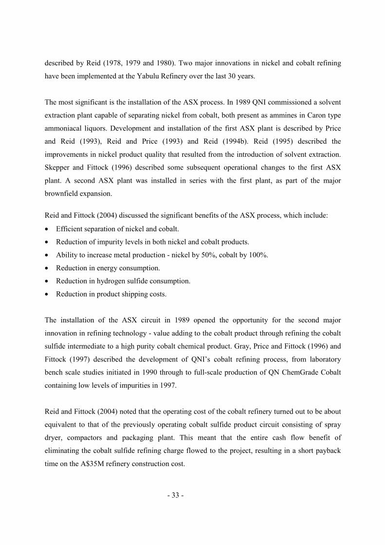
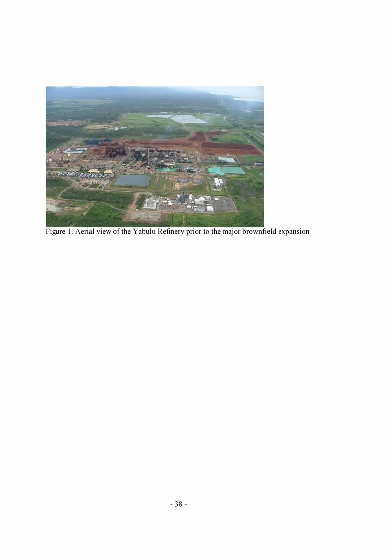
The Yabulu Refinery carries out three major functions – laterite ore processing, mixed nickel-
cobalt hydroxide processing, and nickel and cobalt refining. Figure 1 is an aerial view of the
Yabulu Nickel Refinery prior to the major brownfield expansion, while Figure 2 shows the
Yabulu Nickel Refinery flowsheet in 2007 after the major brownfield expansion.
Figure 1. Aerial view of the Yabulu Refinery prior to the major brownfield expansion
Figure 2. Yabulu Refinery flowsheet in 2007 after the major brownfield expansion
The ore processing section comprises receival of shipments of imported nickel laterite ore,
blending, drying, milling and reduction roasting at about 750°C using Herreshoff multiple hearth
furnaces. The reduced ore is cooled and then leached in ammonia ammonium carbonate liquor at
atmospheric pressure to selectively dissolve nickel and cobalt. Product liquor (PL, typically 10 to
12 g/L Ni and 0.6 g/L Co) is separated from the tailings solids in an eight thickener washing
circuit. Tailings slurry is steam stripped to recover ammonia prior to disposal in storage ponds.
The PL from the ore processing section contains excess ammonia, part of which is utilised to
dissolve further nickel and cobalt in the mixed nickel-cobalt hydroxide processing section. The
- 5 -
resultant concentrated product liquor (CPL, typically 23 g/L Ni and 1.1 g/L Co) is separated from
the residual solids (mainly manganese and magnesium carbonates), which are sent to the washing
circuit in the ore processing section.
In the metal refining section of the refinery, the remaining excess ammonia in the CPL is
removed by controlled steam stripping, enabling nickel to be separated from cobalt using QNI’s
patented ammoniacal solvent extraction (ASX) technology. Nickel is selectively extracted, and
then stripped from the nickel-loaded solvent using concentrated ammonia ammonium carbonate
solution. The resultant nickel loaded strip liquor (Ni LSL, typically 75 to 80 g/L Ni, 0.05 g/L Cu
and 0.02 g/L Co) is further purified by selective copper sulfide precipitation to 0.001 g/L Cu, and
then steam stripped to precipitate basic nickel carbonate solids (BNC, typically 52% dry wt Ni).
The slurry is dewatered using thickeners and pressure filters. The BNC solids are calcined in
rotary kilns, either in an oxidising atmosphere to produce nickel oxide products (NiO, typically
78% Ni, granular and powder forms), or in a reducing atmosphere to produce a nickel
metal/oxide calcine (approximately 60% nickel metal and 40% nickel oxide, typically 90 to 92%
Ni). The nickel metal/oxide calcine is further reduced to typically 97.5% Ni in travelling-belt
furnaces using sawdust and hydrogen reductants. The resultant nickel powder is pressed into
compacts, which are sintered and further reduced to typically 99% Ni in travelling-belt furnaces
using hydrogen reductant, prior to packaging for sale.
The raffinate from the ammoniacal solvent extraction circuit (typically 1.0 g/L Co and 0.02 g/L
Ni) is sulfided using ammonium hydrosulfide solution. Cobalt sulfide solids are separated using a
thickener, allowing the barren liquor to be recycled to the washing circuit in the ore processing
section. Cobalt sulfide solids are oxidatively dissolved using air and oxygen to produce a crude
cobalt sulfate solution, from which the zinc, iron, nickel, sulfur, magnesium and calcium
impurities are selectively removed using three solvent extraction stages and one ion exchange
stage. The resultant high purity cobalt ammine solution (typically 65 g/L Co and <0.001 g/L Ni)
is steam stripped to precipitate chemical grade cobalt oxide/hydroxide solids. The slurry is
dewatered using a thickener, pressure filter and fluid bed drier, and the cobalt oxide/hydroxide
solids are packaged for sale.
NICKEL LATERITE ORE TREATMENT

- 6 -
Characteristics of imported ore
The Yabulu Refinery processes 3.75 million wet t/a of imported ore from over 15 mines in New
Caledonia, Indonesia and the Philippines. The ores vary in mineralogy, moisture content and
handling ability. Imported ore is a combination of high iron limonitic ore (primarily goethite),
manganese-iron oxides (asbolan) and high magnesium, high silica saprolitic ore (primarily
serpentine). Nickel and cobalt association with each ore type is variable. Moisture content
averages 35% and varies between 30 and 40% depending on ore types and weather circumstances
at the mine, load port, Townsville and Yabulu. The moisture content affects the ore handling
ability, with low moisture content leading to excessive dustiness, and high moisture content
causing stickiness. The laterite ore feed to the Yabulu Refinery has the typical composition
shown in Table 1.
Table 1. Typical composition of imported nickel laterite ore
Bulk materials handling
Approximately 75 ore shipments of between 40 kt and 60 kt are received each year. QNI’s ore
handling infrastructure at Townsville Port includes an automated ore unloader capable of
handling 1200 t/h, wharf-side hoppers and conveyor system, grizzly and crushing station, a
dedicated rail loop and automatic train load-out station. Rocks larger than 15 cm are screened
using the triple deck grizzly, and then crushed. The ore is automatically loaded onto trains at a
rate of 1920 t/h. The ore is railed 25 km to Yabulu Refinery; each train has 33 wagons of 60 t
capacity each.
Ore receival
The wagons are unloaded by means of a Noyes rotary tippler. An apron feeder beneath the
unloader feeds the ore onto a conveyor system, which transfers the ore to a radial stacker and
onto the 30 kt capacity live stockpile. A 16 kg sample is extracted from each ore carriage using a
platform-mounted backhoe. A representative composite of all wagon samples for each ore
shipment is prepared and assayed for payment.

- 7 -
Solar drying and ore blending
Yabulu Refinery’s ore dryers were designed to process Greenvale ore, which typically contained
25% moisture. Solar drying is undertaken to reduce the moisture content of the imported ores
from typically 35% to 28%, where it can be readily handled in the feed system to the plant’s three
dryers. Gordon (2003) described the history, development and benefits of solar drying of ore at
Yabulu.
Excavators load the wet ore from the rail car receival stockpile into haul trucks, which transport
the ore to designated areas. Trucks dump the ore in rows on the lay-down pads, which are then
leveled with a bulldozer and/or excavator into a 30 cm thick layer. The ore is then ploughed and
turned over on a daily basis for four to six days, until it is <30% moisture. It is then wheel rolled
by empty trucks and another layer is constructed on top of it. Once the required number of layers
is in place and the pad is full and dried to target, the reclaiming begins; this is done with
excavators scraping the face of the stockpile, taking a vertical cut through each layer, loading
trucks that run to the reclaim feeder. The horizontal multi-layer lay-down and vertical cut reclaim
supports ore blending requirements.
In wet weather the drying pads are wheel rolled by empty trucks driving back and forth over the
surface. A layer of approximately 30 kt, laid out in an area of 130 m x 270 m, can be sealed in
one hour by the use of four haul trucks offset by a wheel width. The resulting seal is effective
even in heavy rain.
The benefits of the solar drying process are improved ore handling with less blockages and
downtime, reduced fuel consumption in drying, and blending of substantially different ores from
a variety of mines. This allows for long-term treatment of ores without large grade variations and
delivers downstream stabilisation of plant and processes to maximise throughput and recoveries.
Ore drying
The ore drying plant consists of one coal seam gas-fired and two coal-fired rotary dryers, each
with a nominal water evaporation capacity of 50 t/h. The 34 m long dryers are co-currently fired.
The ore is dried to nominally 6% moisture content. The discharge gas from the dryers is cleaned
- 8 -
to recover the entrained fines in two stages - multiclones and electrostatic precipitators. The dust,
which constitutes up to 10% of total throughput, is pneumatically pumped directly to the roaster
feed bins, bypassing the grinding plant.
Ore grinding
The dried ore is conveyed to a 2 kt surge bin, which feeds two parallel Hardinge 3 MW dry-
grinding ball mills. The ore milling rate is typically 150 to 200 dry tonnes per mill operating
hour, and the power requirement is typically 8 to 12 kWh per dry tonne of ore milled. Each 4.7 m
diameter by 4.6 m long mill contains a ball load of approximately 150 t and is charged with 7.5
cm diameter forged steel balls. The mills are air swept with a classification system returning the
oversize material to the mill feed. The typical particle size distribution of the product is:
99.5% < 850 microns
95% < 355 microns
80% < 150 microns
70% < 90 microns
55% < 45 microns
The dried, ground ore is transported pneumatically to four 3 kt live storage silos in the ore
reduction section.
Ore reduction
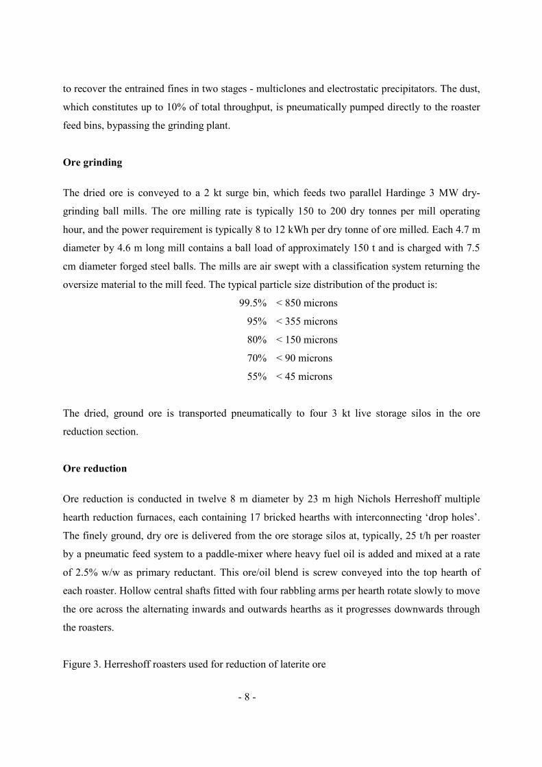
Ore reduction is conducted in twelve 8 m diameter by 23 m high Nichols Herreshoff multiple
hearth reduction furnaces, each containing 17 bricked hearths with interconnecting ‘drop holes’.
The finely ground, dry ore is delivered from the ore storage silos at, typically, 25 t/h per roaster
by a pneumatic feed system to a paddle-mixer where heavy fuel oil is added and mixed at a rate
of 2.5% w/w as primary reductant. This ore/oil blend is screw conveyed into the top hearth of
each roaster. Hollow central shafts fitted with four rabbling arms per hearth rotate slowly to move
the ore across the alternating inwards and outwards hearths as it progresses downwards through
the roasters.
Figure 3. Herreshoff roasters used for reduction of laterite ore
- 9 -
Eleven external combustion chambers installed at hearths 7, 9, 11, 13, 15 and 17 (numbered from
the top) on each roaster are fired with heavy fuel oil at nominally 60% combustion stoichiometry
to provide the necessary energy for roasting. Secondary air is added in hearths 5 and 7 to combust
the remaining hydrogen and carbon monoxide.
As the ore moves downwards through the roasters it is heated by counter-current contact with
combustion gases and radiant energy from the brickwork to initiate dehydroxylation and then
reduction reactions. Dehydroxylation occurs over a range of temperatures from around 350oC
(goethite) up to 650oC (serpentine). Once the metal oxides have been liberated, reduction with
carbon monoxide and hydrogen (from oil decomposition and sub-stoichiometric operation of
combustion chambers) occurs at temperatures up to 750oC. The nickel, cobalt and iron oxides in
the ore are reduced to reactive metals to varying extents. Metal sulfides are also formed by
reaction of sulfur (from the 3% sulfur fuel oil) with the ore. Typically less than 20% of the iron
oxide in the ore feed is reduced to metal, with the majority of iron being present as magnetite in
the reduced ore.
Reduced ore discharges from hearth 17 of each roaster at >700°C and is cooled to <250°C inside
3.0 m diameter by 26 m long rotary coolers partly immersed in water baths.
The off-gas from the top of each roaster passes through a set of cyclones and the recovered dust
is returned to the furnace. An induced draught fan on each roaster off-gas flue delivers the gases
to electrostatic precipitators for final cleaning.
Willenborg (1985) and Hobson and Piper (2002) described some of the many improvements in
ore reduction and roaster operations that have been achieved at Yabulu.
Reduced ore leaching and washing
Archimedes screws at the discharge end of the reduced ore coolers transfer the solids into sealed
chutes connected to launders, where the reduced ore is mixed with the ammonia ammonium
carbonate plant leach solution. Approximately 1800 m3/h of leach liquor from thickener No 1
overflow is cooled to about 25°C in two banks of plate heat exchangers, using water-cooling
- 10 -
followed by refrigeration. The slurry of reduced ore and leach liquor is collected in the agitated
quench slurry tanks, and then pumped to distribution boxes that feed the four parallel leaching
trains, each comprised of a series of four 150 m3 agitated aeration tanks.
Up to 600 m3/h of leach liquor from thickener No 2 overflow is cooled to about 35°C in a bank of
plate heat exchangers using water-cooling, and then partially sulfided to precipitate cobalt as a
mixed cobalt-nickel sulfide, which is separated in a clarifier for use as a reductant in the MHP
treatment section. The cobalt-depleted leach liquor is pumped to the distribution boxes that feed
the reduced ore leaching trains.
Iron, nickel and cobalt present in the reduction roasted laterite ore as alloys and sulfides react
with oxygen from the air and dissolve in the ammonia ammonium carbonate leach solution. Iron
dissolves initially as a ferrous (Fe2+) ammine complex, and is rapidly oxidised to ferric (Fe3+) and
precipitates. Nickel forms stable ammine complexes such as Ni(NH3)62+. Cobalt initially forms
cobaltous (Co2+) ammine complexes, which are further oxidised to very stable cobaltic (Co3+)
ammine complexes. Sulfide is oxidised and dissolves initially as thiosulfate (S2O32-), which is
slowly further oxidised to sulfite (SO32-) and then sulfate (SO4
2-).
Mackenzie and Lumsdaine (2002) showed that some soluble cobalt is lost by co-precipitation and
also adsorption with the fresh iron precipitate. Lowering the soluble cobalt concentration in the
leach liquor from thickener No 2 overflow has the benefit of decreasing these losses. The
leaching reactions are exothermic, and the temperature of the leach slurry increases to 40 - 45°C.
Cooling the leach liquor prior to its mixing with the reduced ore is critical as both the soluble
cobalt loss and evaporation of ammonia increase with temperature during leaching. The oxygen-
depleted air from the aeration process carries considerable ammonia and carbon dioxide vapours,
which are recovered as weak leach liquor (WLL) by scrubbing with water.
Product liquor (PL, typically 10 to 12 g/L Ni, 0.6 g/L Co, 95 g/L NH3, 60 g/L CO2 and pH 10.5)
is separated from the waste solids by counter-current decantation (CCD) washing with barren
ammonia ammonium carbonate solution in a series of eight thickeners. The 45 m diameter
thickeners are fitted with cable torque arms and are fully covered to prevent loss of ammonia and
- 11 -
carbon dioxide. Final metal dissolutions from reduced ore after washing are typically 80 to 82%
Ni and 50 to 60% Co.
Disposal of washed tailings
The underflow slurry from thickener No 8 in the CCD circuit (typically 60% w/w solids) contains
the reduced ore tailings, MHP leach tailings and a substantial amount of ammonia and carbon
dioxide. The tailings pulp is completely steam stripped of ammonia and carbon dioxide in four
parallel tailings stills, which include a direct preheater tower, an agitated magnesium
crystallisation tank, a 2.4 m diameter by 20 m high 12-tray stripping still and a bottoms flash
vessel. The internals of each tailings still are cleaned using high pressure water blasting every 4
weeks to remove magnesium carbonate scale. The stripped tailings discharge to a sump and are
pumped to the tailings ponds for storage.
MIXED NICKEL-COBALT HYDROXIDE TREATMENT
Characteristics of MHP
Ravensthorpe MHP is an amorphous hydroxide, containing nickel and cobalt in conjunction with
lesser amounts of manganese, magnesium, sulfate, and other trace elements. The MHP is “as
received” filter cake product and has not been dried or extruded. MHP has the following typical
composition.
Table 2. Typical composition of Ravensthorpe MHP
MHP receival
MHP from Ravensthorpe is transported by approximately 17 shipments per annum of 430 x 26 t
high-top containers by ship to Townsville Port, and then delivered by rail to a storage area at the
Yabulu Refinery at a peak rate of approximately 50 containers per day.
MHP leaching
- 12 -
Three stages of leaching of MHP in ammoniacal liquors are used for the extraction of nickel and
cobalt.
Repulp A container tipper rotates the full MHP containers and dumps the MHP into a hopper with live
bottom screw feeders. The feeders reduce the lump size and move the MHP forward into a
collection screw conveyor that in turn discharges into the repulper. An attrition scrubber is used
to repulp the MHP with a small flow of PL, giving slurry of consistent composition, without any
lumps. The repulped slurry is stored in two 350 m3 agitated surge tanks.
Primary leach
In the primary leach stage, the remaining PL is combined with slurry from the MHP slurry surge
tanks in a series of four 475 m3 aerated, agitated reactors. The available ammonia and ammonium
carbonate in PL is utilised to solubilise approximately 90% of the nickel and cobalt. Overflow
from the secondary MHP leach thickener is also added to the first reactor so that the
configuration becomes counter-current. Overflow slurry from the last reactor gravitates into the
17.5 m diameter primary leach thickener, and the resultant overflow called concentrated product
liquor (CPL, typically 23 g/L Ni and 1.1 g/L Co) is forwarded to the preboil stills for further
treatment.
Reductant preparation
A reductant, in the form of a cobalt-nickel sulfide (CoNiS, typically Co:Ni >2), is used in the
secondary leach stage to enhance the dissolution of nickel and cobalt. CoNiS reductant serves to
undo MHP aging effects due to oxidation and any refractory association of cobalt and nickel with
oxidised manganese and cobalt compounds. The required amount of CoNiS reductant is produced
from partial sulfiding of the soluble Co and Ni in the overflow stream from thickener No 2 of the
CCD washing circuit in the ore treatment section. Ammonium hydrosulfide is metered in-line to
the thickener No 2 overflow solution to precipitate a cobalt-nickel sulfide. The resulting slurry is
thickened in a 19.5 m diameter clarifier. The cobalt-depleted overflow returns to the distribution
boxes that feed the reduced ore leaching trains, while the underflow is used as the reductant for
MHP leaching.
- 13 -
Secondary leach
Underflow from the primary MHP leach thickener, Fresh Leach Liquor (FLL, typically >120 g/L
NH3 and >60 g/L CO2, sourced from the gas recovery section and at a temperature of
approximately 65°C) and CoNiS slurry from the CoNiS clarifier are combined to form the
secondary leach feed slurry. Secondary MHP leach comprises a series of five 84 m3 agitated
reactors. FLL is introduced into the secondary leach as lixiviant to give higher ammonia
concentrations than in the primary leach. The CoNiS reductant is added in excess to that amount
required for reaction with the oxidised compounds. The portion of the reductant that reacts in this
process is solubilised. The last three reactors in the MHP secondary leach are sparged with air to
oxidise and solubilise the remaining CoNiS reductant. Secondary leaching is followed by liquid-
solid separation in a 15.5 m diameter secondary thickener. Secondary thickener overflow is
returned to the primary MHP leach.
CCD washing
The MHP leach tailings from the secondary thickener underflow are combined with the reduced
ore tailings in the CCD circuit in the ore treatment section. Final MHP leach dissolutions are
obtained by washing the residue in the CCD circuit where metal concentrations are comparatively
low and the ammonia concentration is comparatively high, both favouring the enhancement of
nickel and cobalt dissolutions from MHP. Final metal dissolutions from MHP after the CCD
washing are typically 99.5% Ni and 97.5% Co.
NICKEL-COBALT SEPARATION
Preboil
CPL is pumped from the MHP primary leach thickener overflow at typically 400 m3/h and stored
in two 2400 m3 storage tanks. CPL is subjected to controlled partial distillation (‘preboil’) in four
multi-tray distillation columns. The CPL feed to the preboil stills is preheated by the preboil still
discharge in a bank of recuperative plate heat exchangers. Low-pressure steam at 70 kPag is
injected at the bottom of these stills, driving off part of the dissolved ammonia and carbon

- 14 -
dioxide to provide an appropriate ammonia concentration in the solution for subsequent efficient
nickel solvent extraction. As a result, impurities such as iron, manganese and some magnesium
precipitate from the solution, as well as a small amount of nickel and cobalt. The reduction in
ammonia concentration serves to weaken the nickel ammine complex, which enhances the
subsequent solvent extraction of nickel from the liquor. The internals of each preboil still are
cleaned using high pressure water blasting every 6 weeks to remove scale.
The preboil still discharge slurry containing approximately 0.3 g/L of solids is fed to a 15 m
diameter clarifier. Further precipitation of solids occurs in the clarifier. The clarifier overflow
solution, called special product liquor (SPL, typically 21.5 g/L Ni, 1.0 g/L Co, 45 g/L NH3 and
25 g/L CO2) and at a temperature of about 90°C, is used to preheat the preboil still feed. The SPL
clarifier underflow slurry is filtered and washed on a horizontal belt vacuum filter. The filtrate is
recycled to the SPL clarifier, while the filter cake is transferred to the incoming ore stockpile and
hence returned to the roasters for recovery of the contained nickel and cobalt.
SPL oxidation and filtration
SPL is pumped through a series of three 2400 m3 storage tanks. Prior to entering each tank, SPL
is injected with air and mixed in an in-line mixer, to oxidise Co2+ ions to Co3+. The oxidised SPL
is filtered using three Kelly filters in order to remove trace solids. Precoat is used to aid filtration
and prevent ultra-fine solids from passing through the filter cloths. The filtrate is transferred into
the filtered SPL surge tank. In the SPL feed line to the ammoniacal solvent extraction circuit, the
SPL temperature is controlled using a steam heated plate heat exchanger and a small amount of
hydrogen peroxide solution is injected to oxidise any residual Co2+ ions to Co3+.
Ammoniacal solvent extraction plants
Equipment Two ammoniacal solvent extraction (ASX) circuits operate in series (with respect to the feed
aqueous stream) to selectively separate nickel from cobalt. The first ‘scalp’ ASX circuit consists
of two extraction stages in series and three stripping stages in series. The second ‘follow’ ASX
circuit consists of three extraction stages in series and four stripping stages in series.

- 15 -
All of the extract and strip stages are conventional mixer-settler units. All mixer-settler cells in
the scalp ASX circuit have three mixers in series with the third mixer overflowing into the settler.
In the follow ASX circuit, only E3 and S4 cells have three mixers in series; the remaining cells
have two mixers in series. The operating temperature range is 50 to 60°C, and all cells are sealed
to contain ammonia vapors.
The cells are fabricated in stainless steel on elevated steel platforms with a bunded area below for
spillage, with sufficient height for pipe work and maintenance access below the cells. Cell to cell
pipe work is run below the settler support platform.
Nickel extraction
The ASX organic has a typical loading capacity of >14 g/L Ni; it consists of approximately 15%
v/v 2-hydroxyl-5-nonyl-acetophenone oxime extractant (the active component of LIX 84) and 8%
v/v isotridecanol modifier in an aliphatic diluent. Typical flow rates are 560 m3/h scalp organic
and 400 m3/h follow organic.
The extraction and stripping of nickel in the ASX process can be represented as follows:
[Ni(NH3)n]CO3 (aq) + 2RH (org) ⇌ NiR2 (org) + (n-2)NH3 (aq) + (NH4)2CO3 (aq) where 2 < n < 6, and RH represents the oxime extractant.
Any Co2+, copper, manganese and iron ions present in the SPL feed are also extracted into the
organic, but zinc in the SPL feed is not extracted and remains with the relatively inert Co3+
ammine complexes in the follow raffinate.
The feed SPL to the scalp ASX plant typically contains 21.5 g/L Ni and 1.0 g/L Co. In the scalp
ASX circuit, nickel is partially extracted from the SPL into the scalp ASX organic stream. The
scalp aqueous raffinate stream containing approximately 9 g/L Ni is pumped via the scalp
raffinate transfer tank to feed the follow ASX circuit. The temperature is controlled by a steam
heated plate heat exchanger. The aqueous raffinate stream exiting the final follow extraction
stage typically contains 1.0 g/L Co, <0.05 g/L Ni and <0.1 g/L Zn.
- 16 -
Nickel stripping
The scalp nickel-loaded organic is pumped directly to the scalp strip circuit where it is contacted
counter-currently with a concentrated ammoniacal ammonium carbonate strip liquor (SL,
typically 250 to 300 g/L NH3). Nickel is transferred from the loaded organic into SL producing
the scalp nickel loaded strip liquor (Ni LSL, typically 75 g/L Ni). The stripped organic is
recycled back to the scalp extraction circuit.
Similarly, the nickel-loaded organic in the follow ASX circuit is pumped directly to the follow
stripping circuit where it is contacted counter-currently with SL. Nickel is transferred from the
loaded organic into SL producing the follow Ni LSL. The stripped organic is recycled back to the
follow extraction circuit.
Organic cleaning and regeneration Oxidation of the cobalt in SPL feed to the ASX process is never 100% and some reduction of
Co3+ ions back to the Co2+ state also takes place due to reaction with thiosulfate. Any Co2+ ions in
the SPL are extracted from aqueous solution into the organic phase by a similar reaction to nickel
ions. Some then undergo oxidation to Co3+, which bind strongly with the oxime extractant and
are then not stripped in the nickel stripping stages using concentrated ammonia ammonium
carbonate solution.
The oxime-based organic extractant in the ASX organic is slowly hydrolysed to the
corresponding ketone by the strong ammonia solutions used in the process. The ketone is retained
in the organic phase.
Separate organic cleaning and regeneration plants treat small bleed streams of the stripped
organic from the scalp and follow ASX circuits, to maintain the organic solutions in the two
circuits at typically <3 g/L Co and <2% v/v ketone.
COBALT PRECIPITATION AND REFINING
- 17 -
Cobalt sulfide precipitation and washing
Cobalt bearing raffinate from the follow ASX extraction circuit is contacted with ammonium
hydrosulfide to precipitate the cobalt, zinc and remaining nickel as a mixed sulfide, which is
thickened in a 33 m diameter thickener.
The sulfided liquor containing negligible nickel, cobalt and zinc overflows from the thickener
into an aeration tank to oxidise any residual ammonium hydrosulfide. About two-thirds of the
barren liquor is returned to thickener No 8 in the ore washing CCD thickener circuit and the
remainder sent to the tailings stills.
The thickened cobalt sulfide pulp is washed using water in two more counter-current stages to
partially remove dissolved calcium and magnesium. The slurry is then transferred to the two
cobalt sulfide stripping stills (1.2 m diameter by 21.5 m high) where 70 kPag steam is injected to
recover ammonia and carbon dioxide. The off-gas reports to the gas recovery section. The still
bottoms report to a thickener for a further stage of solids washing and concentration.
The majority of the cobalt sulfide slurry is transferred to the stage 1 leach circuit in the cobalt
refinery, which has a capacity of approximately 2000 t/a cobalt. Impure cobalt sulfide feedstock
in excess of the cobalt refining capacity is filtered, packaged in bulk bags and sold as an
intermediate product.
Table 3. Typical composition of cobalt hydroxy hydrosulfide solids
Stage 1 – Cobalt sulfide leaching and clarification
Cobalt sulfide feed slurry (typically 10% w/w solids) is first leached in a series of six agitated
aeration tanks at 80°C for approximately 24 h, which typically results in >90% cobalt dissolution.
Leach slurry exiting the atmospheric leach is further leached using oxygen in a 16 m3 horizontal
brick-lined autoclave with four compartments, at 500 kPag and 110°C for approximately 2 h.
Typically >99% extent of cobalt dissolution is achieved and the pH of the final slurry is <2.

- 18 -
Leach slurry exiting the autoclave is flashed to atmospheric pressure and clarified in a 2 m
diameter high-rate thickener to separate residual solids. The thickened underflow pulp is pumped
to a two-stage vacuum belt filter and the solids are washed in two counter-current steps with
water. The residue from the belt filter (predominantly elemental sulfur) is discharged directly into
bulk bags for disposal. The thickener overflow stream is polished using bag filters, then indirectly
water-cooled to ~60°C. Hydrogen peroxide solution is injected to oxidise Fe2+ ions to Fe3+.
Stage 2 - Zinc and iron removal by solvent extraction
The crude cobalt sulfate solution feed to stage 2 typically contains >50 g/L Co, 2.5 g/L Ni, 5 g/L
Zn and 0.1 g/L Fe; the flow rate is typically 6 m3/h. The stage 2 solvent extraction circuit is
comprised of ten conventional mixer-settlers. The organic contains approximately 12% v/v
bis(2,4,4-trimethylpentyl) phosphinic acid extractant (the active component of Cyanex 272) in an
aliphatic diluent and the flow rate is typically 6 m3/h.
Zinc and iron are selectively extracted in four extract cells. The pH is controlled between 2.5 in
the first cell, E1 and 3.5 in the last cell, E4 using aqueous ammonia addition. Zinc in the raffinate
stream is typically <0.001 g/L.
Zinc- (and iron) loaded solvent is scrubbed in two cells using dilute sulfuric acid to minimise
transfer of cobalt. Spent scrub solution enters E1. Scrubbed loaded organic is stripped in four
cells using dilute sulfuric acid to produce the acidic zinc loaded strip liquor (Zn LSL, typically
>30 g/L Zn).
Stage 3 – Cobalt transfer to ammine solution by solvent extraction
The objective of this stage is to transfer the cobalt (and nickel) to an organic phase and convert
the cobalt to ammine complexes during stripping. This transfer eliminates sulfate and other
anions such as chloride from the final product, and allows the removal of nickel by QNI's
patented ASX process in stage 4.
- 19 -
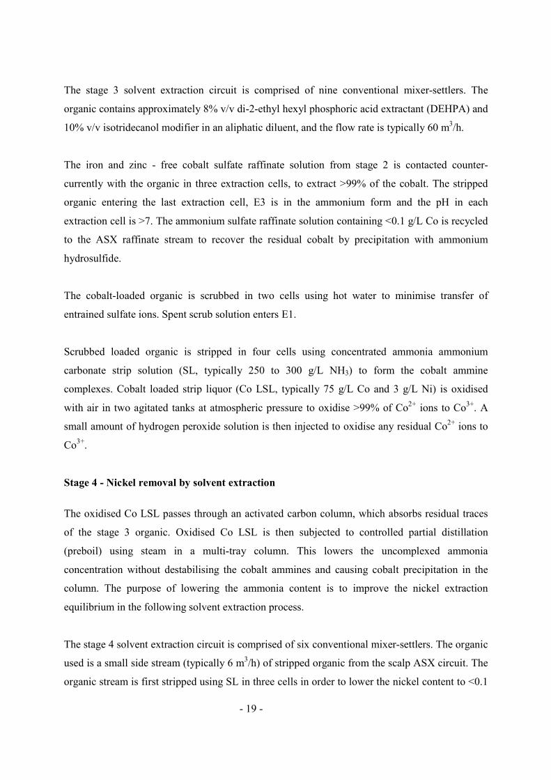
The stage 3 solvent extraction circuit is comprised of nine conventional mixer-settlers. The
organic contains approximately 8% v/v di-2-ethyl hexyl phosphoric acid extractant (DEHPA) and
10% v/v isotridecanol modifier in an aliphatic diluent, and the flow rate is typically 60 m3/h.
The iron and zinc - free cobalt sulfate raffinate solution from stage 2 is contacted counter-
currently with the organic in three extraction cells, to extract >99% of the cobalt. The stripped
organic entering the last extraction cell, E3 is in the ammonium form and the pH in each
extraction cell is >7. The ammonium sulfate raffinate solution containing <0.1 g/L Co is recycled
to the ASX raffinate stream to recover the residual cobalt by precipitation with ammonium
hydrosulfide.
The cobalt-loaded organic is scrubbed in two cells using hot water to minimise transfer of
entrained sulfate ions. Spent scrub solution enters E1.
Scrubbed loaded organic is stripped in four cells using concentrated ammonia ammonium
carbonate strip solution (SL, typically 250 to 300 g/L NH3) to form the cobalt ammine
complexes. Cobalt loaded strip liquor (Co LSL, typically 75 g/L Co and 3 g/L Ni) is oxidised
with air in two agitated tanks at atmospheric pressure to oxidise >99% of Co2+ ions to Co3+. A
small amount of hydrogen peroxide solution is then injected to oxidise any residual Co2+ ions to
Co3+.
Stage 4 - Nickel removal by solvent extraction
The oxidised Co LSL passes through an activated carbon column, which absorbs residual traces
of the stage 3 organic. Oxidised Co LSL is then subjected to controlled partial distillation
(preboil) using steam in a multi-tray column. This lowers the uncomplexed ammonia
concentration without destabilising the cobalt ammines and causing cobalt precipitation in the
column. The purpose of lowering the ammonia content is to improve the nickel extraction
equilibrium in the following solvent extraction process.
The stage 4 solvent extraction circuit is comprised of six conventional mixer-settlers. The organic
used is a small side stream (typically 6 m3/h) of stripped organic from the scalp ASX circuit. The
organic stream is first stripped using SL in three cells in order to lower the nickel content to <0.1

- 20 -
g/L. The organic then extracts nickel (and traces of copper, manganese and iron) from the
oxidised, preboiled Co LSL in three cells. Nickel in the raffinate stream is <0.001 g/L. Both the
nickel loaded strip liquor stream and nickel-loaded organic stream are recycled to the scalp ASX
circuit.
Stage 5 – Calcium and magnesium removal by ion exchange
The final purification step is the removal of magnesium and calcium by ion exchange. The
nickel-free Co LSL feed solution typically contains 70 g/L Co, <0.1 g/L Mg and <0.01 g/L Ca.
The cobalt solution is first passed through an activated carbon column that absorbs residual traces
of the organic used in nickel removal, preventing fouling of the ion exchange resin or
contamination of the final product. Calcium and magnesium are removed in two ion exchange
columns in series. There are a total of four 2 m3 columns, allowing one column to be regenerated
and one column to be on standby. Cross-linked macroreticular cation resins bonded to a
styrene/divinylbenzene support, with an iminodiacetic functional group are used. The resin is
changed to the ammonium form prior to loading. The regeneration sequence comprises the
following steps:
1. Rinse with ammonia solution, to remove cobalt liquor from the column;
2. Strip cobalt, magnesium and calcium using dilute sulfuric acid;
3. Regenerate to ammonium form using ammonia solution.
The product solution from the ion exchange circuit is discharged to the precipitation circuit.
Stage 6 - Cobalt precipitation
The purified cobalt ammine liquor is stripped using steam in a 22 m3 horizontal stainless steel
autoclave with five agitated compartments. The autoclave discharge slurry is flashed to
atmospheric pressure and fed into a 2 m diameter high-rate thickener. The thickener underflow
containing 35% w/w solids is filtered in a continuous belt pressure filter. The filtrate is returned
to the thickener while the filter cake is discharged for drying and packaging.
Stage 7 - Drying and packing
The filter cake has a residual moisture content in the range of 15 to 22% w/w. A portion is
packaged for sale and the remainder fed to a fluid bed dryer to produce a free flowing powder
- 21 -
with 8 to 11% w/w moisture content. The cobalt oxide/hydroxide product is packaged in bulk
bags and containerised for shipping.
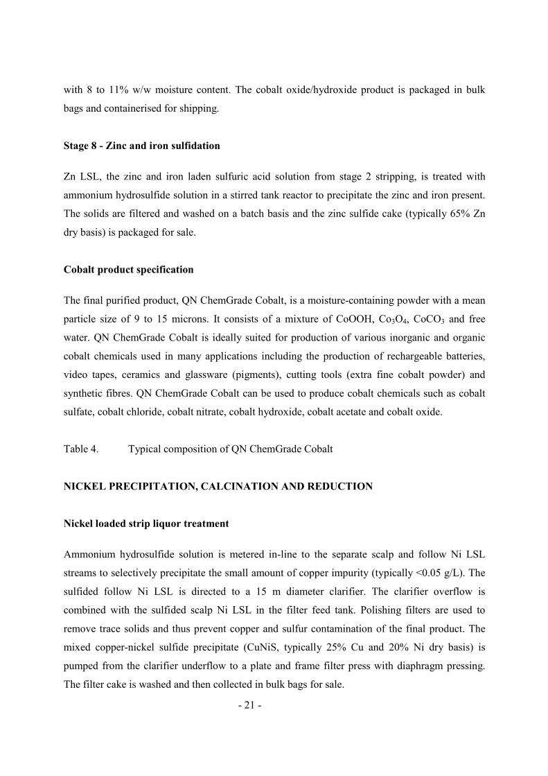
Stage 8 - Zinc and iron sulfidation
Zn LSL, the zinc and iron laden sulfuric acid solution from stage 2 stripping, is treated with
ammonium hydrosulfide solution in a stirred tank reactor to precipitate the zinc and iron present.
The solids are filtered and washed on a batch basis and the zinc sulfide cake (typically 65% Zn
dry basis) is packaged for sale.
Cobalt product specification
The final purified product, QN ChemGrade Cobalt, is a moisture-containing powder with a mean
particle size of 9 to 15 microns. It consists of a mixture of CoOOH, Co3O4, CoCO3 and free
water. QN ChemGrade Cobalt is ideally suited for production of various inorganic and organic
cobalt chemicals used in many applications including the production of rechargeable batteries,
video tapes, ceramics and glassware (pigments), cutting tools (extra fine cobalt powder) and
synthetic fibres. QN ChemGrade Cobalt can be used to produce cobalt chemicals such as cobalt
sulfate, cobalt chloride, cobalt nitrate, cobalt hydroxide, cobalt acetate and cobalt oxide.
Table 4. Typical composition of QN ChemGrade Cobalt
NICKEL PRECIPITATION, CALCINATION AND REDUCTION
Nickel loaded strip liquor treatment
Ammonium hydrosulfide solution is metered in-line to the separate scalp and follow Ni LSL
streams to selectively precipitate the small amount of copper impurity (typically <0.05 g/L). The
sulfided follow Ni LSL is directed to a 15 m diameter clarifier. The clarifier overflow is
combined with the sulfided scalp Ni LSL in the filter feed tank. Polishing filters are used to
remove trace solids and thus prevent copper and sulfur contamination of the final product. The
mixed copper-nickel sulfide precipitate (CuNiS, typically 25% Cu and 20% Ni dry basis) is
pumped from the clarifier underflow to a plate and frame filter press with diaphragm pressing.
The filter cake is washed and then collected in bulk bags for sale.

- 22 -
Basic nickel carbonate precipitation
Sulfided and filtered Ni LSL is fed to four parallel stills that completely strip off ammonia and
ammonium carbonate to precipitate the nickel ions as basic nickel carbonate (BNC, typically
52% Ni dry basis). The feed liquor is first preheated using hot overflow from the BNC product
thickeners in recuperative plate heat exchangers. BNC slurry from the downstream thickeners is
recycled as a seeding material to promote particle growth in order to improve the dewatering
properties. The 2.7 m diameter by 24 m high stills have fourteen single bubble cap plates, which
gradually silt due to the precipitating nickel, resulting in increasing pressure drop across a still.
Each still is chemically cleaned using ammonia leach solution every four days.
The BNC slurry is processed in one of two independent parallel nickel reduction plants, Line 1
and Line 2. Line 2, which was commissioned in 2007 as part of the brownfield expansion to
process MHP from the Ravensthorpe Nickel project, has a nominal capacity of 45 kt/a Ni
compared with 33 kt/a Ni for Line 1. In each nickel reduction plant the basic nickel carbonate
slurry is dewatered prior to reporting to a rotary kiln – reduction furnace – sinter furnace circuit
for calcination, reduction and sintering into saleable nickel compacts.
Basic nickel carbonate dewatering
Dewatering is accomplished in two stages: thickening to 35-40 %w/w solids in two high-rate
thickeners, and filtering to >60 %w/w solids. The Line 1 thickener is 18 m diameter and the Line
2 thickener is 23 m diameter. More than one half of the total thickener underflow is returned to
the Ni LSL stills as seedings. The remainder of the thickener underflow is further dewatered in
two Larox pressure filters. A portion of the BNC filter cake is packaged in bulk bags for sale. In
the event of either calciner being off-line, BNC slurry from the thickener underflows is stored in
two 2700 m3 agitated slurry storage tanks. The overflows from both thickeners are combined and
pumped to settling ponds via the recuperative plate heat exchangers that preheat the Ni LSL still
feed.
Basic nickel carbonate calcination
- 23 -
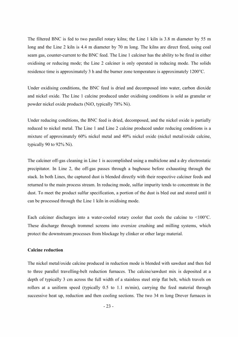
The filtered BNC is fed to two parallel rotary kilns; the Line 1 kiln is 3.8 m diameter by 55 m
long and the Line 2 kiln is 4.4 m diameter by 70 m long. The kilns are direct fired, using coal
seam gas, counter-current to the BNC feed. The Line 1 calciner has the ability to be fired in either
oxidising or reducing mode; the Line 2 calciner is only operated in reducing mode. The solids
residence time is approximately 3 h and the burner zone temperature is approximately 1200°C.
Under oxidising conditions, the BNC feed is dried and decomposed into water, carbon dioxide
and nickel oxide. The Line 1 calcine produced under oxidising conditions is sold as granular or
powder nickel oxide products (NiO, typically 78% Ni).
Under reducing conditions, the BNC feed is dried, decomposed, and the nickel oxide is partially
reduced to nickel metal. The Line 1 and Line 2 calcine produced under reducing conditions is a
mixture of approximately 60% nickel metal and 40% nickel oxide (nickel metal/oxide calcine,
typically 90 to 92% Ni).
The calciner off-gas cleaning in Line 1 is accomplished using a multiclone and a dry electrostatic
precipitator. In Line 2, the off-gas passes through a baghouse before exhausting through the
stack. In both Lines, the captured dust is blended directly with their respective calciner feeds and
returned to the main process stream. In reducing mode, sulfur impurity tends to concentrate in the
dust. To meet the product sulfur specification, a portion of the dust is bled out and stored until it
can be processed through the Line 1 kiln in oxidising mode.
Each calciner discharges into a water-cooled rotary cooler that cools the calcine to <100°C.
These discharge through trommel screens into oversize crushing and milling systems, which
protect the downstream processes from blockage by clinker or other large material.
Calcine reduction
The nickel metal/oxide calcine produced in reduction mode is blended with sawdust and then fed
to three parallel travelling-belt reduction furnaces. The calcine/sawdust mix is deposited at a
depth of typically 3 cm across the full width of a stainless steel strip flat belt, which travels on
rollers at a uniform speed (typically 0.5 to 1.1 m/min), carrying the feed material through
successive heat up, reduction and then cooling sections. The two 34 m long Drever furnaces in
- 24 -
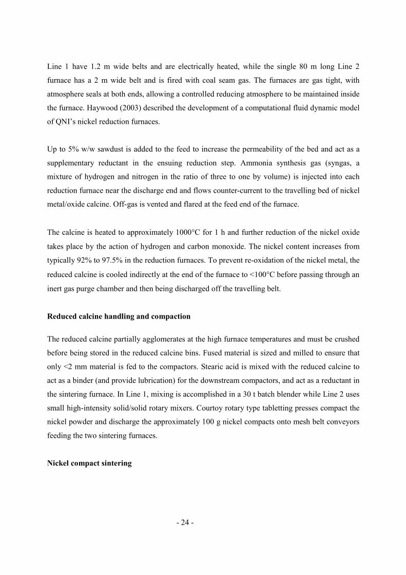
Line 1 have 1.2 m wide belts and are electrically heated, while the single 80 m long Line 2
furnace has a 2 m wide belt and is fired with coal seam gas. The furnaces are gas tight, with
atmosphere seals at both ends, allowing a controlled reducing atmosphere to be maintained inside
the furnace. Haywood (2003) described the development of a computational fluid dynamic model
of QNI’s nickel reduction furnaces.
Up to 5% w/w sawdust is added to the feed to increase the permeability of the bed and act as a
supplementary reductant in the ensuing reduction step. Ammonia synthesis gas (syngas, a
mixture of hydrogen and nitrogen in the ratio of three to one by volume) is injected into each
reduction furnace near the discharge end and flows counter-current to the travelling bed of nickel
metal/oxide calcine. Off-gas is vented and flared at the feed end of the furnace.
The calcine is heated to approximately 1000°C for 1 h and further reduction of the nickel oxide
takes place by the action of hydrogen and carbon monoxide. The nickel content increases from
typically 92% to 97.5% in the reduction furnaces. To prevent re-oxidation of the nickel metal, the
reduced calcine is cooled indirectly at the end of the furnace to <100°C before passing through an
inert gas purge chamber and then being discharged off the travelling belt.
Reduced calcine handling and compaction
The reduced calcine partially agglomerates at the high furnace temperatures and must be crushed
before being stored in the reduced calcine bins. Fused material is sized and milled to ensure that
only <2 mm material is fed to the compactors. Stearic acid is mixed with the reduced calcine to
act as a binder (and provide lubrication) for the downstream compactors, and act as a reductant in
the sintering furnace. In Line 1, mixing is accomplished in a 30 t batch blender while Line 2 uses
small high-intensity solid/solid rotary mixers. Courtoy rotary type tabletting presses compact the
nickel powder and discharge the approximately 100 g nickel compacts onto mesh belt conveyors
feeding the two sintering furnaces.
Nickel compact sintering
- 25 -
The two travelling-belt compact sintering furnaces are similar to the reduction furnaces. The 58
m long furnace in Line 1 has a 1.2 m wide belt and is electrically heated, while the 61 m long
Line 2 furnace has a 2 m wide belt and is heated using coal seam gas-fired radiant elements.
Compacts are continuously fed onto the welded stainless steel mesh furnace belts as a single layer
through an atmosphere seal section and then pass into the heat-up, burn-off and furnace sections
that heat and sinter the compacts at approximately 900°C for 1 h. Syngas is injected into each
sintering furnace near the discharge end and flows counter-current to the travelling bed of nickel
compacts, to accomplish the final reduction to nickel metal. Off-gas is vented and flared at the
feed end of the furnace. The nickel content increases from typically 97.5% to >99% in the
sintering furnaces.
After the heating sections, the compacts travel through a slow cooling section where they
exchange heat with the counter-current syngas stream. The compacts then enter the Convecool
section where high velocity impingement of a cooled recirculating gas ensures rapid cooling.
Finally, the product exits through the discharge purge chamber before being discharged from the
travelling belt at typically <100°C.
Packing
In Line 1, the compacts discharge from the sinter furnace into a single 10 t hopper. In Line 2, the
sintered compacts are transferred to two 72 t live capacity storage hoppers, each on load cells.
The product is discharged into 2 t bags or directly into 25 t containers. The bags and containers
are weighed before sale.
Nickel product specifications
QN Nickel Carbonate, produced as a moist filter cake consisting of a mixture of amorphous
nickel hydroxide and nickel carbonate, is ideally suited for production of various inorganic and
organic nickel chemicals used in many applications.
QN Nickel Oxide, produced in both fine powder and granular forms, is suitable for production of
soft ferrite powders, pigments and catalysts.
- 26 -
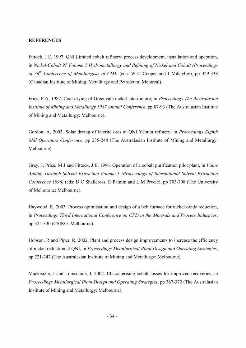
QN Nickel Compacts and QN HiGrade Nickel metal products, produced in the form of 30 mm
cylindrical compacts with two flat sides to eliminate rolling on conveyors, are designed for use
by the nickel alloy, stainless steel and specialty steel industries.
Table 5. Typical compositions of QNI nickel products
Figure 5. QNI Nickel Compacts
GAS RECOVERY SECTION
Steam stripping stills
Ammonia and carbon dioxide gases are recovered from various streams: -
• Ni LSL is steam stripped in four parallel stills to precipitate a purified slurry stream
containing nickel as BNC for further processing in the final nickel products section.
• Ore tailings slurry underflow from thickener No 8 in the CCD circuit and some other waste
streams are steam stripped to produce ammonia-free streams suitable for discharging to the
tailings storage facility.
• CPL is partially steam stripped in four preboil stills to produce SPL for further processing in
the ASX plants.
• Cobalt sulfide slurry is steam stripped in two stills to produce an ammonia-free stream
suitable for acid leaching in the cobalt refinery.
• Weak leach liquor (WLL, typically 10 to 30 g/L NH3) from scrubbers in the ore and MHP
leaching sections, along with WLL from scrubbers in various other areas of the plant, is steam
stripped in two stills to produce ammonia-free water suitable for scrubbing ammonia rich off-
gas from the leaching circuits.
Figure 4. Steam stripping columns used for ammonia and carbon dioxide recovery
Gas cooler condensers

- 27 -
The first stage of gas recovery from off-gases from the various stills is gas cooling and
condensing. This is performed in the water-cooled gas cooler condensers (GCC). These heat
exchangers are either plate and frame or shell and tube. The condensate is a concentrated
ammonia ammonium carbonate solution (typically 250 to 300 g/L NH3 and 180 to 240 g/L CO2),
most of which is forwarded to the various solvent extraction circuits for use as strip liquor. The
remainder is added to the FLL stream.
Absorbers
In the second stage of gas recovery, the off-gases from the GCCs are contacted counter-currently
in packed column absorbers with part of the overflow of thickener No 6 in the CCD circuit. The
absorbers are filled with Pall rings in order to increase the contact surface area. The absorption is
exothermic; therefore the absorber solution is continuously recycled through external water-
cooled plate heat exchangers. A bleed of the absorber solution is returned to thickener No 5 in the
CCD circuit as FLL. A portion of the FLL is transferred without cooling to the MHP secondary
leach.
The final off-gases from the gas absorption area are scrubbed using water in order to minimise
atmospheric emissions.
AUXILIARY PLANT
Most reagents and utilities required by the process are prepared on site. These include process
gases, power, steam, several water grades, and compressed air. Reagents of note include
ammonia synthesis gas, carbon dioxide gas, aqua-ammonia solution and ammonium hydrosulfide
solution.
Power and steam
The original plant design utilised three oil-fired boilers (No 1, 2 & 3), each with a maximum
continuous rating of 114 t/h, for both power and steam generation. A new, large, pulverised coal-
fired boiler (No 4) was commissioned in 1982 in response to the oil crisis. Boiler No 4, with a
maximum continuous rating of 249 t/h, satisfied the total steam demand until the site expansion
- 28 -
in 2007. Boiler No 3 was converted from oil to coal seam gas in 2006 and operated in parallel to
boiler No 4 to meet total process steam demand. The two oil-fired boilers (No 1 & 2) are
available to provide backup.
Three 12.5 MW turbo-generators supply most of the plant requirement for power and 70 kPag
turbine back pressure steam is used for ammonia and carbon dioxide distillation from process
liquor and tailings streams. The refinery is synchronised with the state power grid and purchased
power is available to meet peak demand of approximately 40 MW or while a turbine is out of
service.
Steam at three different pressures; high pressure (HP), medium pressure (MP) and low pressure
(LP) is sourced as follows and distributed plant wide via an integrated piping network:
• HP steam (at 4.1 MPag) is generated by the boilers and is primarily used in the on-site
generation of power. The remainder is distributed to the plant as high and medium pressure
steam.
• MP steam is supplied at a range of pressures (ie 205, 345, 460, 1040 & 2770 kPag) and is
generated from HP steam by letdown stations in the boiler house and in local areas of the
plant.
• LP steam (at 70 kPag) is power turbine exhaust steam and is distributed along major LP
steam headers for use at the various stills (i.e. preboil, Ni LSL, tailings, cobalt sulfide and
water management). Supplementary LP steam demand is met by de-superheating HP steam in
the boiler house. Any excess due to power generation / process steam demand imbalance is
vented.
Gas plant
The plant consists of several units, namely, the two coal seam gas reformers, the carbon dioxide
recovery system (Benfield system using potassium carbonate), an ammonia plant, an ammonium
hydrosulfide production unit and a carbon dioxide absorption plant. Reformed coal seam gas is
used to produce ammonia synthesis gas (syngas, a mixture of hydrogen and nitrogen in the ratio
of three to one by volume). Syngas is used for production of hydrogen sulfide and ammonia, and
as reductant for nickel reduction and sinter furnace operations. The plant supplies aqueous
ammonia solution (typically 25% w/w NH3) to the process for make up and ammonium
- 29 -
hydrosulfide solution (typically 12 % w/w H2S) for precipitation of cobalt-nickel sulfide, cobalt
sulfide, copper-nickel sulfide and zinc sulfide. Additional anhydrous ammonia is purchased to
meet the total plant ammonia requirement of approximately 15 kt/a. Carbon dioxide from the
reforming plant is purified and used to make up losses in the process and for inert gas purging
needs. Additional carbon dioxide requirements are provided by recovery from boiler No 3 off-
gases.
Water supply
The Yabulu Refinery consumes on average 20 000 m3/d of water, which is supplied by:
• borefield make-up to the main site reservoir
• municipal water primarily from the Mt. Spec reservoir.
Water is treated in several steps and a range of water types is distributed plant wide via an
integrated piping network - boiler feed water, process water, demineralised water, cooling water,
fire water, potable water, service water and recycle water.
Reverse osmosis plant
The Yabulu plant site borders the coast of Halifax Bay. Historically ocean discharge was the
accepted method to manage excess tailings water volumes, within the license conditions set by
the Environmental Protection Agency. Scott and Richardson (2001) described the commissioning
of a reverse osmosis (RO) water regeneration plant in 2000, which has allowed up to 12 000 m3/d
of tailings water to be recycled for re-use in the plant. This has the dual benefits of eliminating
the practice of effluent discharge to the sea and reducing the quantity of bore water that is
pumped to the plant. Clean water is combined with service water in the reservoir. The RO brine is
pumped to saline evaporation ponds.
Cooling water Cooling water is supplied to the plant through two independent sets of cooling towers at an
average temperature of 33°C. Cooling water is treated in the cooling tower basins with various
chemicals to inhibit corrosion, disperse sludge and to control the pH. Sodium chlorite is also

- 30 -
injected into the cooling water to inhibit algae growth. Water is constantly blown down to waste
to control suspended solids, TDS and chlorides.
Compressed air
Compressors at the power plant produce plant air at a delivery pressure between 620 and 690
kPag. Instrument air is produced at similar pressures by removing water and oil from plant air.
Compressed air is distributed plant wide.
Energy
Heavy fuel oil is shipped into the Townsville Port and pumped 25 km through a dedicated buried
pipeline to two 25 kt storage tanks at the Yabulu plant site. About 160 kt/a of oil is used in the
ore roasters and through intermittent use of the standby boilers No 1 & 2.
Coal from the Collinsville Mine (300 km south of Townsville) is railed to Yabulu and stored on a
20 kt stockpile. About 330 kt/a of coal is used in the ore dryers and boiler No 4.
Coal seam gas is supplied by pipeline from coalfields in the Bowen Basin. Approximately 5 PJ/a
of gas is used in one ore dryer, the gas production plant, the nickel production plant and boiler No
3.
PROCESS CONTROL AND ANALYSIS
The Yabulu Refinery has eight separate Control Rooms across the plant, which are being
progressively connected to the ABB System6 Distributed Control System (DCS). Most
equipment is controlled remotely from the Control Rooms and the plant is generally controlled
automatically during normal operation.
A Production Information Management System (PIMS) provides real-time and historical data to
assist with process analysis, management and reporting as well as on-going improvement. All
personnel have access to the PIMS through their desktop PC’s connected to the plant IT network.
The PIMS is based on an OSIsoft PI data historian, which collates data from the ABB System6

- 31 -
DCS, several Process Logic Controllers in the production areas, electronic logbooks used by
plant operators and maintainers, and the Laboratory Information Management System in the
central analytical laboratory. The analytical laboratory provides all chemical analyses required
for quality control of the nickel and cobalt refining processes, and analyses of the ore shipment
samples, MHP shipment samples and final nickel and cobalt product lot samples.
PRODUCTION COSTS
The Yabulu Nickel Refinery has been in operation since 1974, and has undergone many changes
that have affected the production costs of the nickel and cobalt products. In addition to the costs
of purchasing the imported laterite ore and MHP feed stocks, there are significant production
costs associated with operation of the complex metallurgical refinery including energy,
maintenance, labour and reagents. Reid (1996) and Reid and Barnett (2002) compared the
production costs of the Yabulu Nickel Refinery with those of other nickel operations. Some of
the major changes that have made Yabulu a more cost competitive nickel and cobalt producer are
described below.
Feed stocks
The Yabulu plant was built to process ore from the Greenvale ore-body, which never fulfilled the
original expectations in terms of either nickel grade (from original drilling results) or metal
recovery (from piloting results). It made good sense to locate the refinery on the coast rather than
adjacent to the ore-body, to allow for future ore importation. (The bulk of the world’s nickel
laterite deposits lie in the Asia Pacific region.) Reid (1994a) described the change of nickel
laterite ore source from the domestic Greenvale Mine to imports from New Caledonia, Indonesia
and the Philippines. Reid (1996) noted that as a consequence, the delivered ore cost to Yabulu is
relatively high, being above US$1.00/lb contained Ni (varies with currency exchange rates, etc),
and is a major unit cost. Reid and Fittock (2004) noted that a most significant impact of the
progressive change from Greenvale to imported ore was an increase in nickel and cobalt
production due to the higher grades and recoveries associated with the imported ore. In the ten
years between 1979 and 1989, nickel production from Greenvale ore had been about 20 kt/a and
cobalt production averaged about 900 t/a. During the five-year transition to processing 100%

- 32 -
imported ore in 1995, nickel production progressively increased by nearly 2 kt/a to 28.7 kt/a and
cobalt by more than 100 t/a to 1480 t/a.
Rather than increase ore imports as a means to expand production further, the recent brownfield
expansion has been based on the treatment of a mixed nickel-cobalt hydroxide concentrate. This
required an expansion of the nickel and cobalt refining sections of the Yabulu operation, while
the ore treatment section was not affected. As a consequence of the economies of scale achieved
through this expansion, the production cost (US$/lb Ni) and labour efficiency (t
Ni/employee/year) have been significantly lowered.
Energy
The Yabulu Refinery was originally designed with oil as the primary fuel. In the years
immediately following commissioning in 1974, the project suffered from the four-fold increase in
the oil price. Consequently there has been a progressive shift to cheaper energy sources. Fries
(1987) described the changeover of two ore dryers to coal-fed spreader grate stoker air heaters
(commissioned in 1981) and the installation of the pulverised coal-fired boiler No 4 to replace the
three oil-fired boilers (commissioned in 1982). Following the change from domestic Greenvale
ore to the higher moisture imported ore in the 1990’s, solar drying was chosen in preference to
building a fourth coal-fired dryer.
A pipeline to supply coal seam gas (predominantly methane) to Yabulu was completed in 2004,
prior to the recent major brownfield expansion. Thus the Line 2 nickel calciner, reduction furnace
and sinter furnace are designed with coal seam gas-firing. The remaining oil-fired dryer, naphtha-
fired Line 1 calciner, one of the three oil-fired boilers and the naphtha-fired syngas plant were
converted to coal seam gas in 2006. Conversion of the oil-fired burners on the ore roasters to coal
seam gas is currently being studied, however it involves some technical risk to the process and is
costly.
Refining technology
The original design of the Yabulu Refinery, based on the Caron process of reduction roasting and
ammonia ammonium carbonate leaching to dissolve nickel and cobalt as ammine complexes, is
- 33 -
described by Reid (1978, 1979 and 1980). Two major innovations in nickel and cobalt refining
have been implemented at the Yabulu Refinery over the last 30 years.
The most significant is the installation of the ASX process. In 1989 QNI commissioned a solvent
extraction plant capable of separating nickel from cobalt, both present as ammines in Caron type
ammoniacal liquors. Development and installation of the first ASX plant is described by Price
and Reid (1993), Reid and Price (1993) and Reid (1994b). Reid (1995) described the
improvements in nickel product quality that resulted from the introduction of solvent extraction.
Skepper and Fittock (1996) described some subsequent operational changes to the first ASX
plant. A second ASX plant was installed in series with the first plant, as part of the major
brownfield expansion.
Reid and Fittock (2004) discussed the significant benefits of the ASX process, which include:
• Efficient separation of nickel and cobalt.
• Reduction of impurity levels in both nickel and cobalt products.
• Ability to increase metal production - nickel by 50%, cobalt by 100%.
• Reduction in energy consumption.
• Reduction in hydrogen sulfide consumption.
• Reduction in product shipping costs.
The installation of the ASX circuit in 1989 opened the opportunity for the second major
innovation in refining technology - value adding to the cobalt product through refining the cobalt
sulfide intermediate to a high purity cobalt chemical product. Gray, Price and Fittock (1996) and
Fittock (1997) described the development of QNI’s cobalt refining process, from laboratory
bench scale studies initiated in 1990 through to full-scale production of QN ChemGrade Cobalt
containing low levels of impurities in 1997.
Reid and Fittock (2004) noted that the operating cost of the cobalt refinery turned out to be about
equivalent to that of the previously operating cobalt sulfide product circuit consisting of spray
dryer, compactors and packaging plant. This meant that the entire cash flow benefit of
eliminating the cobalt sulfide refining charge flowed to the project, resulting in a short payback
time on the A$35M refinery construction cost.
- 34 -
REFERENCES
Fittock, J E, 1997. QNI Limited cobalt refinery: process development, installation and operation,
in Nickel-Cobalt 97 Volume 1 Hydrometallurgy and Refining of Nickel and Cobalt (Proceedings
of 36th Conference of Metallurgists of CIM) (eds: W C Cooper and I Mihaylov), pp 329-338
(Canadian Institute of Mining, Metallurgy and Petroleum: Montreal).
Fries, F A, 1987. Coal drying of Greenvale nickel lateritic ore, in Proceedings The Australasian
Institute of Mining and Metallurgy 1987 Annual Conference, pp 87-93 (The Australasian Institute
of Mining and Metallurgy: Melbourne).
Gordon, A, 2003. Solar drying of laterite ores at QNI Yabulu refinery, in Proceedings Eighth
Mill Operators Conference, pp 235-244 (The Australasian Institute of Mining and Metallurgy:
Melbourne).
Gray, J, Price, M J and Fittock, J E, 1996. Operation of a cobalt purification pilot plant, in Value
Adding Through Solvent Extraction Volume 1 (Proceedings of International Solvent Extraction
Conference 1996) (eds: D C Shallcross, R Paimin and L M Prvcic), pp 703-708 (The University
of Melbourne: Melbourne).
Haywood, R, 2003. Process optimisation and design of a belt furnace for nickel oxide reduction,
in Proceedings Third International Conference on CFD in the Minerals and Process Industries,
pp 325-330 (CSIRO: Melbourne).
Hobson, R and Piper, R, 2002. Plant and process design improvements to increase the efficiency
of nickel reduction at QNI, in Proceedings Metallurgical Plant Design and Operating Strategies,
pp 221-247 (The Australasian Institute of Mining and Metallurgy: Melbourne).
Mackenzie, J and Lumsdaine, I, 2002. Characterising cobalt losses for improved recoveries, in
Proceedings Metallurgical Plant Design and Operating Strategies, pp 367-372 (The Australasian
Institute of Mining and Metallurgy: Melbourne).

- 35 -
Price, M J and Reid, J G, 1993. Separation and recovery of nickel and cobalt in ammoniacal
systems – process development, in Solvent Extraction in the Process Industries Volume 1
(Proceedings of International Solvent Extraction Conference 1993) (eds: D H Logsdail and M J
Slater), pp 159-166 (Elsevier Applied Science: London and New York).
Reid, J G, 1978. Metallurgical operations at the Yabulu nickel refinery of Queensland Nickel Pty
Ltd, in Proceedings The Australasian Institute of Mining and Metallurgy 1978 Annual
Conference, pp 347-354 (The Australasian Institute of Mining and Metallurgy: Melbourne).
Reid, J G, 1979. Operations at the Greenvale nickel project mine and refinery, in International
Laterite Symposium (eds: D J I Evans, R S Shoemaker and H Veltman), pp 368-381 (Society of
Mining Engineers of the American Institute of Mining, Metallurgical, and Petroleum Engineers
Inc: New York, NY).
Reid, J G, 1980. Nickel-cobalt ore leaching by Queensland Nickel Pty Ltd, Yabulu, Qld, in
Australasian Mining and Metallurgy (ed: J T Woodcock), pp 585-590 (The Australasian Institute
of Mining and Metallurgy: Melbourne).
Reid, J G and Price, M J, 1993. Ammoniacal solvent extraction at Queensland Nickel: process
installation and operation, in Solvent Extraction in the Process Industries Volume 1 (Proceedings
of International Solvent Extraction Conference 1993) (eds: D H Logsdail and M J Slater), pp
225-231 (Elsevier Applied Science: London and New York).
Reid, J G, 1994a. The Yabulu nickel refinery transition from Greenvale ore to imported ore, in
Proceedings The Australasian Institute of Mining and Metallurgy 1994 Annual Conference, pp
261-263 (The Australasian Institute of Mining and Metallurgy: Melbourne).
Reid, J G, 1994b. Hydrometallurgy at work – progression from concept to reality, in Proceedings
6th Australasian Institute of Mining and Metallurgy Extractive Metallurgy Conference, pp 11-15
(The Australasian Institute of Mining and Metallurgy: Melbourne).

- 36 -
Reid, J G, 1995. Queensland Nickel – value added products from technological advances, in
Proceedings The Australasian Institute of Mining and Metallurgy 1995 Annual Conference, pp
131-135 (The Australasian Institute of Mining and Metallurgy: Melbourne).
Reid, J G, 1996. Laterite ores – nickel and cobalt resources for the future, in Proceedings Nickel
’96 Mineral to Market (eds: E J Grimsey and I Neuss), pp 11-16 (The Australasian Institute of
Mining and Metallurgy: Melbourne).
Reid, J G, and Fittock, J E, 2004. Yabulu 25 years on, in Proceedings International Laterite
Nickel Symposium 2004 (eds: W P Imrie and D M Lane), pp 599-618 (The Minerals, Metals, and
Materials Society: Pennsylvania).
Reid, J G and Barnett, S C C, 2002. Nickel laterite hydrometallurgical processing update, in
Proceedings ALTA 2002 Nickel/Cobalt 8 (ALTA Metallurgical Services).
Scott, J and Richardson, D, 2001. QNI Yabulu refinery water re-use project, in Proceedings
ALTA 2001 Nickel/Cobalt 7 (ALTA Metallurgical Services).
Skepper, I G and Fittock, J E, 1996. Nickel cobalt separation by ammoniacal solvent extraction:
the operating experience, in Value Adding Through Solvent Extraction Volume 1 (Proceedings of
International Solvent Extraction Conference 1996) (eds: D C Shallcross, R Paimin and L M
Prvcic), pp 777-782 (The University of Melbourne: Melbourne).
Willenborg, J R, 1985. Improvements in roaster operation at Queensland Nickel Pty Ltd, in
Smelting and Refining Operators’ Symposium, pp 155-159 (The Australasian Institute of Mining
and Metallurgy: Melbourne).

- 37 -
List of figure captions
Figure 1. Aerial view of the Yabulu Refinery prior to the major brownfield expansion
Figure 2. Yabulu Refinery flowsheet in 2007 after the major brownfield expansion
Figure 3. Herreshoff roasters used for reduction of laterite ore
Figure 4. Steam stripping columns used for ammonia and carbon dioxide recovery
Figure 5. QNI Nickel Compacts
List of table captions
Table 1 Typical composition of imported nickel laterite ore
Table 2. Typical composition of Ravensthorpe MHP
Table 3. Typical composition of cobalt hydroxy hydrosulfide solids
Table 4. Typical composition of QN ChemGrade Cobalt
Table 5. Typical compositions of QNI nickel products
- 38 -
Figure 1. Aerial view of the Yabulu Refinery prior to the major brownfield expansion

- 39 -
Figure 2. Yabulu Refinery flowsheet in 2007 after the major brownfield expansion
BNC slurry
air
Preboil Solidsto ore
stockpile
NH4HS
Copper-Nickelsulphide product
for sale
PreboilStills
Ni LSLStills
steam
QN HiGrade Nickel &QN Nickel Compact
products for sale
syngas syngas
SinterFurnaces
ReductionFurnaces
coal seam gas
gas cleaningLaroxFilters
steam
steam
air
CompactorTables
Filter
CPL (23 g/L Ni)air
Leaching
residue todisposal
O2
NH4HS
Filter
QN ChemGrade Cobaltproducts for sale
steam
Larox Filter
air
Drying
Flash
Co LSLPreboil Still
steam
Ion ExchangeCa & Mg Removal
Solvent ExtractionZn & Fe Removal
Solvent ExtractionTransfer to Ammine
Solvent ExtractionNi & Cu Removal
Oxidation
Flash
Calcination& Reduction
Kilns
Thickener
Precipitation
CobaltSulphide
Stills
Clarifier
to NH3recovery
to NH3 Recovery
to GCC’s
Clarifier
Thickener
water
to ASX Plant
water
H2SO4
Zn/Fe LSL
H2O2
Oxidation
sawdust
Belt Vacuum Filter
Belt Vacuum Filter
power
coal Power Plant
steamwater
E1E2E3
S1S2
S3S4
E1E2
S1S2
S3
Scalp ASX
Absorbers Gas CoolerCondensers
Thickener
Follow ASX
Filter
MHPPrimaryLeach
Ravensthorpe MHP0.19 M wt/yr
MHPSecondary
Leach air
Thickener
Thickener
SyngasPlant
coal seam gas
air
H2SPlantsulphur
CO2syngas (3H2/N2)NH3
Converter
NH3NH4HS
1
2
3
6
TailingsStills steam
air
airfuel oil
fuel oilgas cleaning
Ball Mills
DustBypass
gas cleaning
Dryersair
coal/coal seam
gas
Imported Ore3.75 M wt/yr
4
5
7
8
PL (10 g/L Ni)
Leaching
Ore ReductionFurnaces (12)
Solar Drying
Tailings Ponds
ReverseOsmosis
Plant
cleareffluent
CoolingWater
Coolers
RefrigerationCoolers
NH4HS
FLL
FLL
CoNiS
air
air
CCDWashingCircuit
Thickener Thickener
Thickener
ThickenerCobalt sulphideproduct for sale
Filter
QN Nickel Carbonateproduct for sale
QN Nickel Oxideproducts for sale
SL
FilterNH4HSZinc sulphide
product for sale
coal seam gas
CO2
Ni LSL(75 g/L Ni)
SPL (21 g/L Ni)
SL
Gas Plant
Plantwater
Brine Pond
ScrubberWaterStills steam
stripped waterto scrubbers
WLL
Filter
Co LSL (75 g/L Co)
SL
Repulp
coolers
ClarifierClarifier
Ni/NiO (92% Ni)
NiO (78% Ni)
97.5% Ni 99% Ni
H2O2
H2O2
PHE
seedings
PHE
water
WLL
Scrubbers
water
WLL
Scrubbers

- 40 -
Figure 3. Herreshoff roasters used for reduction of laterite ore
Figure 4. Steam stripping columns used for ammonia and carbon dioxide recovery
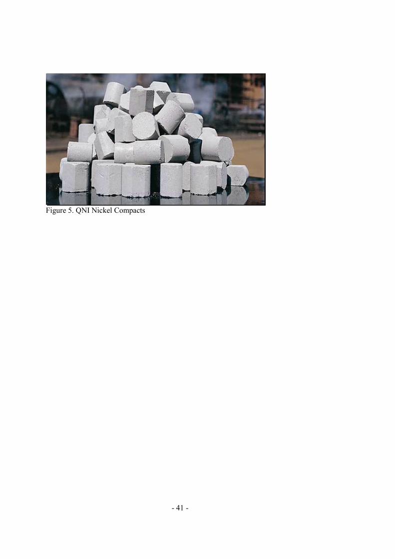
- 41 -
Figure 5. QNI Nickel Compacts

- 42 -
Table 1. Typical composition of imported nickel laterite ore
Chemical Analysis (% w/w dry basis) Moisture (% wet wt) Ni Co Fe Si Mg Mn Cu Zn Ca Al Cr S
35 1.6 0.15 37 7.2 5.2 0.8 0.01 0.05 0.1 2.1 1.2 0.2
Table 2. Typical composition of Ravensthorpe MHP
Chemical Analysis (% w/w dry basis) Moisture (% wet wt) Ni Co Fe Si Mg Mn Cu Zn Ca Al Cr S
41 40 1.4 0.1 0.5 1.8 2.8 0.01 0.2 0.2 0.05 0.01 3.8
Table 3. Typical composition of cobalt hydroxy hydrosulfide solids
Chemical Analysis % w/w dry basis Ca 0.001 - 0.018 Co 38 - 45 Cu 0.002 - 0.007 Fe 0.02 - 0.22 Mg 0.02 - 0.09 Mn 0.002 - 0.10 Ni 1 - 6 S 32 - 36 Si 0.03 - 0.25 Zn 2 - 5

- 43 -
Table 4. Typical composition of QN ChemGrade Cobalt
Chemical Analysis % w/w dry basis Al ≤ 0.002 Bi < 0.001 C ≤ 0.25 Ca ≤ 0.006 Cd ≤ 0.001 Co 64.5 - 67 Cr ≤ 0.002 Cu ≤ 0.001 Fe ≤ 0.002 K < 0.001
Mg ≤ 0.005 Mn ≤ 0.002 N* ≤ 1.25 Na ≤ 0.005 Ni ≤ 0.006 P < 0.002 Pb ≤ 0.001 S ≤ 0.02 Si ≤ 0.03 Zn ≤ 0.002
* analysis on wet sample
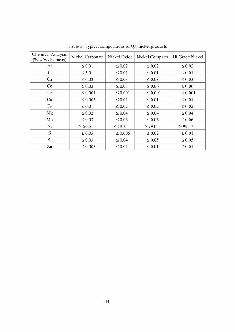
- 44 -
Table 5. Typical compositions of QN nickel products
Chemical Analysis (% w/w dry basis) Nickel Carbonate Nickel Oxide Nickel Compacts Hi Grade Nickel
Al ≤ 0.01 ≤ 0.02 ≤ 0.02 ≤ 0.02 C ≤ 5.0 ≤ 0.01 ≤ 0.01 ≤ 0.01 Ca ≤ 0.02 ≤ 0.03 ≤ 0.03 ≤ 0.03 Co ≤ 0.03 ≤ 0.03 ≤ 0.06 ≤ 0.06 Cr ≤ 0.001 ≤ 0.001 ≤ 0.001 ≤ 0.001 Cu ≤ 0.005 ≤ 0.01 ≤ 0.01 ≤ 0.01 Fe ≤ 0.01 ≤ 0.02 ≤ 0.02 ≤ 0.02 Mg ≤ 0.02 ≤ 0.04 ≤ 0.04 ≤ 0.04 Mn ≤ 0.03 ≤ 0.06 ≤ 0.06 ≤ 0.06 Ni > 50.5 ≤ 78.5 ≥ 99.0 ≥ 99.45 S ≤ 0.05 ≤ 0.005 ≤ 0.02 ≤ 0.01 Si ≤ 0.03 ≤ 0.04 ≤ 0.05 ≤ 0.05 Zn ≤ 0.005 ≤ 0.01 ≤ 0.01 ≤ 0.01

- 45 -
List of Headings
ABSTRACT (Level 1)
PROCESS FLOWSHEET OVERVIEW (Level 1)
NICKEL LATERITE ORE TREATMENT (Level 1)
Characteristics of imported ore (level 2)
Bulk materials handling (level 2)
Ore receival (level 2)
Solar drying and ore blending (level 2)
Ore drying (level 2)
Ore grinding (level 2)
Ore reduction (level 2)
Reduced ore leaching and washing (level 2)
Disposal of washed tailings (level 2)
MIXED NICKEL-COBALT HYDROXIDE TREATMENT (Level 1)
Characteristics of MHP (level 2)
MHP receival (level 2)
MHP leaching (level 2)
Repulp (level 3)
Primary leach (level 3)
Reductant preparation (level 3)
Secondary leach (level 3)
CCD washing (level 3)
NICKEL-COBALT SEPARATION (Level 1)
Preboil (level 2)
SPL oxidation and filtration (level 2)
Ammoniacal solvent extraction plants (level 2)
Equipment (level 3)
Nickel extraction (level 3)
Nickel stripping (level 3)
Organic cleaning and regeneration (level 3)
COBALT PRECIPITATION AND REFINING (Level 1)
Cobalt sulfide precipitation and washing (level 2)
Stage 1 – Cobalt sulfide leaching and clarification (level 2)

- 46 -
Stage 2 - Zinc and iron removal by solvent extraction (level 2)
Stage 3 – Cobalt transfer to ammine solution by solvent extraction (level 2)
Stage 4 - Nickel removal by solvent extraction (level 2)
Stage 5 – Calcium and magnesium removal by ion exchange (level 2)
Stage 6 - Cobalt precipitation (level 2)
Stage 7 - Drying and packing (level 2)
Stage 8 - Zinc and iron sulfidation (level 2)
Cobalt product specification (level 2)
NICKEL PRECIPITATION, CALCINATION AND REDUCTION (Level 1)
Nickel loaded strip liquor treatment (level 2)
Basic nickel carbonate precipitation (level 2)
Basic nickel carbonate dewatering (level 2)
Basic nickel carbonate calcination (level 2)
Calcine reduction (level 2)
Reduced calcine handling and compaction (level 2)
Nickel compact sintering (level 2)
Packing (level 2)
Nickel product specifications (level 2)
GAS RECOVERY SECTION (Level 1)
Steam stripping stills (level 2)
Gas cooler condensers (level 2)
Absorbers (level 2)
AUXILIARY PLANT (Level 1)
Power and steam (level 2)
Gas plant (level 2)
Water supply (level 2)
Reverse osmosis plant (level 3) Cooling water (level 3)
Compressed air (level 2)
Energy (level 2)
PROCESS CONTROL AND ANALYSIS (Level 1)
PRODUCTION COSTS (Level 1)
Feed stocks (level 2)
- 47 -
Energy (level 2)
Refining technology (level 2)
REFERENCES (Level 1)