title 14e electrical code xx - inspectapedia.com · 14e-1-010 adoption of the national electrical...
TRANSCRIPT

Municipal Code of Chicago
TITLE 14EELECTRICAL CODE
Ch. 14E-1 General
Ch. 14E-2 Wiring and Protection
Ch. 14E-3 General Requirements for Wiring Methods and Materials
Ch. 14E-4 Equipment for General Use
Ch. 14E-5 Special Occupancies
Ch. 14E-6 Special Equipment
Ch. 14E-7 Special Conditions
Ch. 14E-8 Communications Systems
Ch. 14E-9 Tables
Ch. 14E-10 Informative Annexes
CHAPTER 14E-1GENERAL
14E-1-010 Adoption of the National Electrical Code by reference.
14E-1-020 Citations.
14E-1-090 Introduction.
14E-1-100 Definitions.
14E-1-110 Requirements for electrical installations.
14E-1-010 Adoption of the National Electrical Code by reference.
NFPA 70, National Electrical Code, 2017 edition (hereinafter known as NFPA 70), is adopted by reference and shall be consideredpart of the requirements of this title except as modified by the specific provisions of this title.
If differences occur between a provision modified by this title and a provision adopted without modification, the modified provisionshall control.
(Added Coun. J. 9-6-17, p. 55278, Art. I, § 1)
14E-1-020 Citations.
Provisions of NFPA 70 which are incorporated into this title by reference may be cited as follows: 14E- [NFPA 70 chapternumber]-[NFPA 70 section number].
Provided that Article 90 of NFPA 70 shall be deemed to be part of Chapter 1, and the informative annexes shall be deemed to bepart of a new Chapter 10.
Citations within this title and within the provisions of NFPA 70 which are incorporated into this title by reference shall be read toincorporate "14E-[chapter number]-" as a prefatory part of the citation.
(Added Coun. J. 9-6-17, p. 55278, Art. I, § 1)
14E-1-090 Introduction.
The provisions of Article 90 of NFPA 70 are adopted by reference with the following modifications:

1. Delete subsection 90.1(C) and the subsequent informational note.
2. Revise subsection 90.2(B)(4) to read:
"Installations of communications equipment under the exclusive control of communications utilities
located outdoors or in building spaces used exclusively for such installations, where such installations are under the jurisdiction of theIllinois Commerce Commission or other State or Federal regulatory body"
3. Revise subsection 90.2(B)(5) to read:
"Installations under the exclusive control of an electric utility where such installations:
a. Consist of service drops or service laterals, and associated metering, or
b. Are located in legally established easements or rights-of-way designated by or recognized by public service commissions, utilitycommissions, or other regulatory agencies having jurisdiction for such installations, or
c. Are on property owned or leased by the electric utility for the purpose of communications, metering, generation, control,transformation, transmission, energy storage or distribution of electric energy."
4. Revise subsection 90.2(C) to read:
"Special Permission. The authority having jurisdiction for enforcing this Code may grant exception for the installation of conductorsand equipment that are not under the exclusive control of the electric utilities and are used to connect the electric utility supply systemto the service conductors of the premises served, provided such installations are outside a building or structure, or terminateimmediately inside a building wall in accordance with Section 13-8-032. Such special permission shall in all cases be obtained from theauthority having jurisdiction in writing prior to the commencement of the installation."
5. Revise section 90.4 to read:
"Enforcement. The authority having jurisdiction for enforcement of the Code has the responsibility for making interpretations of therules, for deciding on the approval of equipment and materials, and for granting the special permission contemplated in a number of therules.
By special permission, the authority having jurisdiction may waive specific requirements in this Code or permit alternative methodswhere it is assured that equivalent objectives can be achieved by establishing and maintaining effective safety. The authority havingjurisdiction may not waive or alter the requirements of 300.22(C)."
6. Revise section 90.6 to read:
"Formal Interpretations. To promote uniformity of interpretation and application of the provisions of this Code, the authorityhaving jurisdiction may issue formal interpretations in accordance with Section 13-8-031."
(Added Coun. J. 9-6-17, p. 55278, Art. I, § 1)
14E-1-100 Definitions.
The provisions of Article 100 of NFPA 70 are adopted by reference with the following modifications:
1. Revise the definition of "Approved" to read:
"Acceptable to the authority having jurisdiction. No equipment, device or appliance covered by the provisions of this Code shall beapproved unless it has been tested by and bears the label of an approved testing laboratory. Any testing laboratory currentlyrecognized as a Nationally Recognized Testing Laboratory (NRTL) by the United States Occupational Health and SafetyAdministration (OSHA) is approved. Self-certification of equipment or installations shall not be acceptable."
2. Revise the definition of "Authority Having Jurisdiction (AHJ)" to read:
"The commissioner of buildings."
3. Insert the following language after the definition of "Building":
"Building, High Rise. A building more than 24.4 m (80 ft) above grade."
4. Insert the following language after the definition of "Electrical Circuit Protective System":

"Electrical Contractor. A person registered pursuant to Chapter 4-290."
5. Insert the following language after the definition of "Handhole Enclosure":
"Hard Surface Ceiling. A ceiling with a finished surface of plaster, drywall, or similar material, specifically excluding acoustical tileor similar types of ceilings."
6. Revise the definition of "In Sight From (Within Sight From, Within Sight)" to read:
"Where this Code specifies that one equipment shall be "in sight from," "within sight from," or "within sight of," and so forth, anotherequipment, the specified equipment is to be visible and not more than 15 m (50 ft) distant from the other and as close as practicable tothe other."
7. Revise the definition of "Qualified Person" to read:
"One who is or is under the direct supervision of a supervising electrician, has skills and knowledge related to the construction andoperation of the electrical equipment and installations and has received safety training to recognize and avoid the hazards involved."
8. Insert the following language after the definition of "Show Window":
"Sign. A name, identification, description, display, illustration or character which is affixed to or represented directly or indirectlyupon a building, structure, or piece of land and which directs attention to an object, product, place, activity, person, institution,organization or business. Furthermore for purposes of Title 14E, signs shall also include anything meeting the definition of "sign" inSection 17-17-02159."
9. Insert the following language after the definition of "Structure":
"Supervising Electrician. A person registered pursuant to Chapter 4-292."
(Added Coun. J. 9-6-17, p. 55278, Art. I, § 1)
14E-1-110 Requirements for electrical installations.
The provisions of Article 110 of NFPA 70 are adopted by reference with the following modifications:
1. Revise section 110.1 by deleting the informational note.
2. Insert new subsection 110.12(C) to read:
"Abandoned Electrical Equipment. All accessible (as applied to wiring methods) abandoned raceways, cables, conductors, boxes,and electrical equipment shall be removed."
3. Insert new subsection 110.26(G) to read:
"Dedicated Electrical Closets. In high rise buildings, where vaults, transformers and/or distribution points are establishedthroughout the various floors or areas of the building, all such electrical equipment shall be grouped and installed in an approvedelectrical closet.
Such electrical closet(s) shall be for the exclusive use of the electrical system and shall be constructed as to provide the requiredworking space around all of the electrical equipment installed therein. Such electrical closet(s) shall have an adequate fire rating and beprotected in an approved manner and shall comply with 230.70.
Where busways serve such electrical closets, the busway shall only pass through areas meeting the fire rating, exclusive use, andfire protection requirements as the electrical closet. Busways located in areas with sprinkler protection shall be of the weatherproof orraintight type."
(Added Coun. J. 9-6-17, p. 55278, Art. I, § 1)
CHAPTER 14E-2WIRING AND PROTECTION
14E-2-200 Use and identification of grounded conductors.
14E-2-210 Branch circuits.
14E-2-215 Feeders.
14E-2-220 Branch circuits, feeders, and service calculations.
14E-2-225 Outside branch circuits and feeders.
14E-2-230 Services.
14E-2-240 Overcurrent protection.
14E-2-250 Grounding and bonding.
14E-2-280 Surge arresters, over 1,000 volts.
14E-2-285 Surge protective devices (SPDs), 1,000 volts or less.
14E-2-200 Use and identification of grounded conductors.
The provisions of Article 200 of NFPA 70 are adopted by reference with the following modification:
1. Insert new subsection 200.5 to read:
"Color Code of Grounded Branch Circuit and Grounded Feeder Circuit Conductors. Grounded branch circuit and groundedfeeder circuit conductors shall be identified in accordance with either 200.5 (A) or (B), as applicable.
(A) 150 Volts to Ground or Less. The grounded conductor of branch circuit and feeder conductors rated 150 volts to ground orless shall be identified by a continuous white outer finish.
(B) Over 150 Volts to Ground. The grounded conductor of branch circuit and feeder conductors rated over 150 volts to groundshall be identified by a continuous gray outer finish."
(Added Coun. J. 9-6-17, p. 55278, Art. I, § 1)
14E-2-210 Branch circuits.
The provisions of Article 210 of NFPA 70 are adopted by reference with the following modifications:
1. Revise subsection 210.5(C)(1) to read:
"Branch Circuit Ungrounded Conductors. Branch circuit ungrounded conductors:
(a) Rated 150 volts to ground or less shall use the following color code: black, red, and blue.
(b) Rated over 150 volts to ground shall use the following color code: brown, orange, and yellow
(c) On a 4-wire, delta-connected system where the midpoint of one phase winding is grounded, the high phase branch circuitconductor shall be durably and permanently marked by an outer finish that is orange in color."
2. Revise subsection 210.6(C) to read:
"277 Volts to Ground. Provided the premises is under the supervision of a supervising electrician, circuits exceeding 120 volts,nominal, between conductors and not exceeding 277 volts, nominal, to ground shall be permitted to supply the following:
(1) Listed electric-discharge or listed light- emitting diode-type luminaires where:
(a) The luminaires shall be installed at least 2.44 m (8 ft) above the floor
(b) the luminaires shall be permanently installed
(c) switching shall be controlled by low voltage control relays or by listed circuit breakers used as switches and marked SWD orHID
(2) Luminaires equipped with mogul-base screw shell lampholders that comply with 210.6(C)(1) requirements
(3) Cord-and-plug-connected or permanently- connected utilization equipment that complies with 210.6(C) (1) requirements"
3. Revise the first clause of subsection 210.6(D) to read:

"600 Volts Between Conductors. Provided the premises is under the supervision of a supervising electrician, circuits exceeding277 volts, nominal, to ground and not exceeding 600 volts, nominal, between conductors shall be permitted to supply the following:"
4. Revise subsection 210.11 by inserting the following language before subsection (A):
"Informational Note: See 210.12 and exceptions for arc-fault circuit-interrupter (AFCI) protection requirements."
5. Revise subsection 210.12 to read:
"Arc-Fault Circuit-Interrupter Protection. Arc- fault circuit-interrupter protection shall be provided as required in 210.12(A),(B), and (C). The arc-fault circuit interrupter shall be installed in a readily accessible location.
(A) Dwelling Units. All 120-volt, single phase, 15- and 20-ampere branch circuits supplying outlets and devices installed indwelling units shall be protected by a listed arc-fault circuit interrupter, combination-type, installed to provide protection of the branchcircuit.
(B) Dormitory Units. All 120-volt, single phase, 15- and 20-ampere branch circuits supplying outlets and devices installed indormitory units shall be protected as described in 210.12(A).
(C) Guest Rooms and Guest Suites. All 120-volt, single-phase, 15- and 20- ampere branch circuits supplying outlets and devicesinstalled in guest suites and guest rooms of hotels and motels shall be protected as described in 210.12(A).
(D) Branch Circuit Extensions or Modifications - Dwelling Units and Dormitory Units. In any of the areas specified in210.12(A) or (B), where branch- circuit wiring is modified, replaced or extended, the branch-circuit shall be protected by one of thefollowing:
(1) A listed combination-type AFCI located at the origin or the branch circuit.
(2) A listed outlet branch-circuit type AFCI located at the first outlet of the existing branch circuit.
Exception No. 1 to 210.12(A), (B), and (C): It shall be permitted to omit AFCI protection for that portion of the branch circuitenclosed in rigid metal conduit (RMC), intermediate metal conduit (IMC), electrical metal tubing (EMT), or Type MI cable sheathmeeting the requirements of 250.118 along with metal outlet and junction boxes.
Exception No. 2 to 210.12(D): It shall be permitted to omit AFCI protection for that portion of the branch circuit installed in rigidmetal conduit (RMC), intermediate metal conduit (IMC), electrical metal tubing (EMT), or steel sheathed cable, Type AC, Type MC,or Type MI cable sheath, meeting the requirements of 250.118, with metal outlet and junction boxes.
Exception No. 3 to 210.12(A), (B), (C) and (D): Where an individual branch circuit to a fire alarm system is installed inaccordance with 760.41(B) or 760.121(B) is installed in rigid metal conduit (RMC), intermediate metal conduit (IMC), electrical metaltubing (EMT), or Type MI Cable sheath meeting the requirements of 250.118, with metal outlet and junction boxes, AFCI protectionshall be permitted to be omitted.
Informational Note No. 1: For information on types of arc-fault circuit interrupters, see UL 1699, Standard for Arc-Fault CircuitInterrupters.
Informational Note No. 2: See 11.6.3(5) of NFPA 72, National Fire Alarm and Signaling Code, for information related tosecondary power supply requirements for smoke alarms installed in dwelling units.
Informational Note No. 3: See 760.41(B) and 760.121(B) for power-supply requirements for fire alarm systems."
6. Revise subsection 210.19(A) to read, with no changes to subsections (A)(2) to (A)(4):
"Branch Circuits Not More Than 600 Volts.
Informational Note No. 1: See 310.15 for ampacity ratings of conductors.
Informational Note No. 2: See Part II of Article 430 for minimum rating of motor branch-circuit conductors.
Informational Note No. 3: See 310.15(A)(3) for temperature limitation of conductors.
Informational Note No. 4: See 215.2(A)(1) for voltage drop requirements on feeder conductors.
(1) General. Branch-circuit conductors shall have an ampacity not less than the maximum load to be served. Conductors shall besized to carry not less than the larger of 210.19(A)(1)(a) or (b).
(a) Where a branch circuit supplies continuous loads or any combination of continuous and noncontinuous loads, the minimumbranch-circuit conductor size shall have an allowable ampacity not less than the noncontinuous load plus 125 percent of the continuousload.
(b) The minimum branch-circuit conductor size shall have an allowable ampacity not less than the maximum load to be servedafter the application of any adjustment or correction factors.
Exception: If the assembly, including the overcurrent devices protecting the branch circuit(s), is listed for operation at100 percent of its rating, the allowable ampacity of the branch-circuit conductors shall be permitted to be not less than thesum of the continuous load plus the noncontinuous load.
Conductors for branch circuits, as defined in Article 100, shall be sized to prevent a voltage drop not to exceed 3 percent at thefarthest outlet of power, heating, and lighting loads, or combinations of such loads, and so that the maximum total voltage drop on bothfeeders and branch circuits to the farthest outlet does not exceed 5 percent."
7. Revise subsection 210.19(B) to read:
"Branch Circuits Over 600 Volts. The ampacity of conductors shall be in accordance with 310.15 and 310.60 as applicable.Branch-circuit conductors over 600 volts shall be sized in accordance with 210.19(B)(1).
(1) General. The ampacity of branch-circuit conductors shall not be less than 125 percent of the designed potential load ofutilization equipment that will be operated simultaneously."
8. Revise section 210.50 by deleting the informational note.
9. Insert new subsections 210.70(A)(2)(5) and (A)(2)(6) to read:
"(5) At least one wall switch-controlled lighting outlet shall be installed in clothes closets and other closets over 2.3m2 (25 ft2).Closet luminaires shall be permanently installed lighting outlets.
(6) At least one wall switch-controlled lighting outlet shall be installed over each sink or basin located in a room or area that isgreater than 5.95 m2 (64 ft2). Such lighting outlets shall be in addition to the general lighting outlets installed in the room or area."
(Added Coun. J. 9-6-17, p. 55278, Art. I, § 1; Amend Coun. J. 11-8-17, p. 59720, § 11)
14E-2-215 Feeders.
The provisions of Article 215 of NFPA 70 are adopted by reference with the following modifications:
1. Revise subsection 215.2(A)(1)(b) to read:
(b) The minimum feeder conductor size shall have an allowable ampacity not less than the maximum load to be served after theapplication of any adjustment or correction factors.
Informational Note No. 1: See Examples D1 through D11 in Informative Annex D.
Informational Note No. 2: See 210.19(A) for voltage drop requirements for branch circuits.
Conductors for feeders, as defined in Article 100, shall be sized to prevent a voltage drop not to exceed 3 percent at the farthestoutlet of power, heating, and lighting loads, or combinations of such loads, and so that the maximum total voltage drop on both feedersand branch circuits to the farthest outlet does not exceed 5 percent."
2. Revise section 215.5 to read:
"Diagrams of Feeders. A diagram showing feeder details shall be provided to the authority having jurisdiction prior to theinstallation of the feeders in accordance with 215.5(A) and (B).
(A) Plans Required. In new or remodeled buildings, complete and detailed electrical plans are required prior to the start of workon the following installations:
(1) Dwelling occupancies in buildings greater than two stories in height
(2) Non-dwelling occupancies in buildings greater than one story in height or greater than 929 m2 (10,000 ft2) in area

(3) New or replacement services or feeders rated 400 amperes or greater
(4) Service switchboards and motor control centers rated in excess of 1200 amperes or 600 volts
(B) Plan Content. The plans shall include where applicable, the following:
(1) A single-line drawing of the service and distribution
(2) Schedule of conduits, wire, switches, circuit breakers, overcurrent devices, transformers, motors and luminaires
(3) Load calculations to verify sizes of services, feeders, and panelboards indicating available fault-current and withstand ratings
(4) Grounding electrode conductor or common grounding electrode conductor system
(5) Equipment layout in switchboard rooms and electrical closets indicating the working space required by 110.26"
3. Revise subsection 215.12(C)(1) to read:
"(1) Feeder Ungrounded Conductors. Feeder ungrounded conductors:
(a) Rated 150 volts to ground or less shall use the following color code: black, red, and blue.
(b) Rated over 150 volts to ground shall use the following color code: brown, orange, and yellow.
(c) On a 4-wire, delta-connected system where the midpoint of one phase winding is grounded, the high phase feeder conductorshall be durably and permanently marked by an outer finish that is orange in color."
(Added Coun. J. 9-6-17, p. 55278, Art. I, § 1; Amend Coun. J. 11-8-17, p. 59720, § 12)
14E-2-220 Branch circuits, feeders, and service calculations.
The provisions of Article 220 of NFPA 70 are adopted by reference without modification.
(Added Coun. J. 9-6-17, p. 55278, Art. I, § 1)
14E-2-225 Outside branch circuits and feeders.
The provisions of Article 225 of NFPA 70 are adopted by reference with the following modifications:
1. Revise section 225.10 to read:
"Wiring on Buildings (or Other Structures). The installation of outside wiring on surfaces of buildings (or other structures) shallbe permitted for circuits of not over 1000 volts, nominal, as the following:
(1) Type MI cable
(2) Rigid metal conduit (RMC)
(3) Intermediate metal conduit (IMC)
(4) Electrical metallic tubing (EMT)
(5) Messenger-supported wiring."
2. Insert new Part IV to read:
"Part IV. Outside Lighting
225.70.General. Part IV lists the requirements for outside lighting on public and private property that are in addition to therequirements of 225.7.
225.71. Commercial Lighting on Public Property.
(A) Supports. Commercial lighting on public property shall be supported on a post erected to support the post under the worstexpected conditions.
Informational Note: For expected conditions in this area, see ANSI C2-2012, National Electrical Safety Code.

(B) Location. Each post shall be installed so that the lower edge of the post shall be on a line with the upper edge of the streetcurb and the center of the post shall be not less than 557 mm (22 in.) from the outer edge of the curb. Where a number of posts areerected or where posts are erected in addition to existing posts, they shall be located so that the globes shall be in a line with eachother.
Exception: In the case of exceptionally narrow sidewalks or where large diameter pole bases are used, the 557 mm (22 in.)dimension may be reduced by the Department of Transportation.
(C) Separation from Fire Hydrants. No post shall be erected closer than 1.5 m (5 ft) to a fire hydrant.
(D) Street Corners. Posts erected at street corners shall not be located in the area defined by extending the building lines or right-of-way lines, if no building is present, to the curb.
(E) Spacing. Where more than one post is installed or where posts are installed in the immediate vicinity of other posts, spacing inany block shall be uniform and not less than 12.2 m (40 ft) nor more than 15.2 m (50 ft).
Exception: Where photometrics are acceptable to the Department of Transportation, a spacing greater than 15.2 m (50 ft) shall bepermitted.
225.72.Commercial Lighting Foundations. All commercial lighting posts require concrete foundations. Concrete foundationsshall be not less than 610 mm (24 in.) by 610 mm (24 in.) or 676 mm (27 in.) in diameter and shall extend below the frost line but notless than 914 mm (36 in.) below grade. Actual foundation dimensions shall be approved by the Department of Transportation.
Exception: Where commercial lighting is installed on vaulted walks or areas, a foundation shall not be required. All such supports anddesigns shall be first approved by the Department of Transportation.
225.74.Attachment to Concrete Foundation. Posts attached to concrete foundations shall be attached by a method which willpermit the removal of the post from its foundation without damage to the post or foundation. Where the method of fastening is bymeans of a spider extending outward from the post base, the top of the foundation before the post is installed shall be left 76 mm (3 in.)below the top surface of the walk.
After the post has been aligned and fastened, the foundation shall be made flush with the top surface of the walk and no part of thespider or bolts shall project above the surface of the walk. In cases where posts are to be installed on unexcavated walk, the surfaceof the walk shall be recessed.
(A) Posts Set on Concrete Foundations. Where posts are set on concrete foundations, they shall be attached by bolts extendinginto and firmly held by the concrete foundation for a distance of not less than 762 mm (30 in.) For concrete posts, there shall be aminimum of three bolts not less than 16 mm (5/8 in.) diameter. The bolts shall be set such that they shall not pull out of the concretenor turn due to the screwing on of a nut.
(B) Bolts. All bolts for attaching of posts shall be hot galvanized.
225.75.Concrete for Foundations. Concrete for foundations shall be made of at least 3000 psi concrete mix with a minimumcement content of 470 lb/yd3 of concrete or shall be standard class SI concrete (IDOT Section 1020). Proper admixtures, such as air-entraining admixture (for concrete exposed to freezing and thawing) and water-reducing admixture (for placement and workability)shall be added to the concrete.
Informational Note: The use of Ready-Mix Concrete per ASTM C94 is recommended.
225.76.Conductors and Wiring for Commercial Lighting on Public Property. Conductors outside of buildings for post lightingcircuits shall be installed in rigid metal conduit, intermediate metal conduit or Schedule 80 nonmetallic rigid conduit a minimum of 610mm (24 in.) beneath the surface of the ground, sidewalks, streets, alleys or parkways, or be enclosed by the post. Conductors withinbuildings shall be run in suitable conduits.
(A) Conductors. Conductors shall consist of a two or three wire cable not smaller than 12 AWG and have an approved insulation.Conductors smaller than 8 AWG shall be supported by a messenger.
(B) Protection Against Physical Damage. Conductors shall be protected from physical damage in accordance with 300.5.
(C) Metallic Sheath. The metallic sheath of cables shall be grounded.
(D) Disconnects. Branch circuits supplying street posts shall be protected by fuses rated not more than 20 amperes.

(E) Splices. Splices shall be made within approved junction boxes inside of buildings and in post heads outside of buildings.
225.81.Supports. Commercial lighting on private property shall be supported on a post erected to support the post under the worstexpected conditions.
Informational Note No. 1: For expected conditions in this area, see ANSI C2-2012, National Electrical Safety Code.
Informational Note No. 2: Planking the pole, "raking" the pole during installation, and similar methods of support should be consideredduring design.
(A) Materials. Supports may be standard wood poles, metal poles if suitably protected against corrosion, or clear timber. Except inhazardous locations, metal poles shall be provided with a hand hole through which the connections to the branch circuits shall bepermitted to be made.
(B) Size and Strength. Minimum strength shall be equivalent to a Class 5 wood pole and in no case less than that required by225.81.
225.82. Conductors and Wiring for Commercial Lighting on Public Property. Conductors shall consist of a two or three wirecable not smaller than 12 AWG and have an approved insulation.
(A) Conductors Smaller than 8 AWG. Conductors smaller than 8 AWG shall be permitted to be a twisted pair or run paralleland taped. They shall be attached to and supported by a messenger at intervals not exceeding 1.52 m (5 ft).
(B) Conductors 8 AWG or Larger. Conductors No. 8 or larger shall use standard strain insulators at supports.
(C) Conductor Spans. Spans attached to buildings shall not exceed 30.5 m (100 ft) in length. Spans supported by clear timbersshall not exceed 18.2 m (60 ft) in length.
(D) Messenger Wires. Messenger wires shall be galvanized and not smaller than 10 AWG.
225.83. Clearances for Commercial Lighting on Public Property.
(A) From Ground or Grade. Conductors shall be installed in accordance with the clearance requirements of 225.18.
(B) Feeder Wires . Feeder wires shall be separated by at least 305 mm (12 in.) and supported on approved insulators of glass orporcelain when not in conduit.
225.84.Disconnects for Commercial Lighting on Public Property. Cutouts and switches installed outdoors shall be in standardweatherproof cabinets. Cabinets installed with the bottom less than 2.44 m (8 ft) above grade shall be locked.
225.85.Connections. Connections in sockets or receptacles shall be of the standard molded "pigtail" weatherproof type.Connections of socket wires shall be staggered.
225.90.Underground Branch Circuits. Where branch circuit conductors are from an underground feed, the requirements of (A)and (B) of this section shall apply.
(A) Underground Branch Circuits Attached to Wood Poles. Where rigid metal conduit or flexible metal conduit, whereapproved, is used it shall be installed a minimum of 2.44 m (8 ft) up the pole and to within 457 mm (18 in.) of the lighting fixture andmade electrically continuous and grounded. Where cord is used it shall contain a separate grounding conductor which shall becontinuous back to the distribution cabinet.
(B) Underground Branch Circuits Attached to Metal Poles. Rigid metal conduit shall be stubbed through the below gradeand fitted with a grounding type bushing. The pole shall be bonded to the conduit with a minimum 8 AWG wire. Where direct buriedconductors or cable or non-metallic raceway is used, a separate grounding conductor shall be provided back to the distribution cabinet.Where rigid metal conduit is used, all segments of the raceway system shall be bonded together and shall be permitted to be used asthe ground.
225.91.Disconnects for Metal Poles. Approved fuseholders shall be permitted to be installed in metal poles provided that they areaccessible to qualified personnel only and there are no live parts exposed.
225.92.Voltages Permitted. Voltages permitted shall be as indicated in 220.5(A). Voltages in excess of 250 volts to ground or 300volts between phase conductors shall be permitted to be used only when the following conditions are met:
(1) The lighting shall be installed not less than 6.7 m (22 ft) above grade

(2) Each pole, if of metal construction, shall be grounded by one of the approved methods
(3) Disconnects shall be located within sight of the lights they control, outdoors, preferably on one of the poles
(4) Where the installation is large or if the location of the lighting does not permit all the lighting to be within sight, more than onedisconnect shall be permitted to be installed
(5) Where snap-switches or push-button type switches are used, the voltage across these switches shall be reduced to less than250 volts to ground or 300 volts between phase conductors
(6) Branch circuits shall be limited to not more than 50 ampere rating
(7) The electrical system shall be under the supervision of a supervising electrician."
(Added Coun. J. 9-6-17, p. 55278, Art. I, § 1)
14E-2-230 Services.
The provisions of Article 230 of NFPA 70 are adopted by reference with the following modifications:
1. Revise subsection 230.30(B) to read:
"Wiring Methods. Underground service conductors shall be installed in accordance with the applicable requirements of this Codecovering the type of wiring method used and shall be limited to the following:
(1) Type RMC conduit
(2) Type IMC conduit
(3) Type HDPE conduit
(4) Type PVC conduit
(5) Type RTRC conduit
(6) Type USE conductors or cables identified for direct burial applications
(7) Type MV cable identified for direct burial applications
(8) Type MI cable, where suitably protected against physical damage and corrosive conditions"
2. Revise section 230.43 to read:
"Wiring Methods for 1000 Volts, Nominal, or Less. Service-entrance conductors shall be installed in accordance with theapplicable requirements of this Code covering the type of wiring method used and shall be limited to the following methods:
(1) Rigid metal conduit
(2) Intermediate metal conduit
(3) Service-entrance cables for existing residential occupancies of not more than three dwelling units
(4) Busways
(5) Cablebus
(6) Mineral-insulated, metal-sheathed cable."
3. Delete section 230.44.
4. Revise section 230.46 to read:
"Spliced Conductors. Service entrance conductors shall only be spliced in accordance with 230.46 (1) through (6):
(1) Clamped or bolted connections in metering equipment enclosures
(2) Where service entrance conductors are tapped from a utility controlled and locked (to prevent unauthorized access) bussed tapbox, to supply two to six disconnecting means grouped at a common location
(3) In an approved utility owned service splice box, where utility sized conductors are connected to conductors that supplycustomers service equipment and are sized to this chapter
(4) A connection shall be permitted where service conductors are extended from a service drop to an outside meter location andreturned to connect to the service entrance conductors of an existing installation
(5) Where the service entrance conductors consist of busway, connections shall be permitted as required to assemble the varioussections and fittings
(6) For existing service-entrance conductors, it shall be permissible to install listed underground splice kits for:
(a) Repair of existing conductors
(b) Extension of conductors by special permission."
5. Revise subsection 230.50(B) to read:
"Above Ground Service Conductors and Cables. Service-entrance conductors installed above ground shall be protected againstphysical damage as specified in 230.50(B)(1) or (B)(2), and shall comply with (B)(3) where applicable.
(1) Service-Entrance Cables. Service-entrance cables, where subject to physical damage, shall be protected by any of thefollowing:
(a) Rigid metal conduit
(b) Intermediate metal conduit
(c) Other approved means
(2) Other Than Service-Entrance Cable. Individual open conductors and cables other than service-entrance cables shall not beinstalled within 3.0 m (10 ft) of grade level or where exposed to physical damage.
Exception: Type MI cable shall be permitted within 3.0 m (10 ft) of grade level where not exposed to physical damage or whereprotected in accordance with 300.5(D).
(3) On Alley Side of Building. Service raceways or service-entrance cable on the alley side of buildings where subject tomechanical injury by vehicles shall be embedded flush in the masonry or concrete wall, or shall be suitably protected up to a height of3.7 m (12 ft) above grade."
6. Revise section 230.51 to read:
"Mounting Supports. Service-entrance cable conductors shall be supported by straps or other approved means within 300 mm (12in.) of ever service head, gooseneck, or connection to a raceway or enclosure and at intervals not exceeding 750 mm (30 in.)."
7. Delete table 230.51(C).
8. Revise subsection 230.70(A) to read:
"(A) Location. The service disconnecting means shall be installed in accordance with 230.70(A)(1), (A)(2), (A)(3), (A)(4), and(A)(5).
(1) One- and Two-Family Dwellings. In one- and two-family dwellings the service disconnecting means shall be installed at areadily accessible location in the basement or first floor of the building at a point not exceeding 1.52 m (5 ft) from the point of entryinto the building. When the length of the service raceway exceeds 1.52 m (5 ft) from the point of entry into the building, the serviceraceway shall conform to the requirements of 230.6.
(2) In Other Than One- and Two-Family Dwellings. In other than one- and two- family dwellings, the service disconnectingmeans shall be installed at a readily accessible location either
outside of the building or structure or inside the building or structure nearest the point of entrance of the service conductors.When the length of the service raceway exceeds 1.52 m (5 ft) from the point of entry into the building, the service raceway shallconform to the requirements of 230.6.
(3) Bathrooms. Service disconnecting means shall not be installed in bathrooms.

(4) Remote Control. Where a remote control device(s) is used to actuate the service disconnecting means, the servicedisconnecting means shall be located in accordance with 230.70(A)(1).
(5) High Rise Buildings. In high rise buildings and other similar buildings of large area, the disconnecting means for the multipleservices recognized by 230.2(B)(2) shall be located in a dedicated fire-rated room as near as practical to the serving utility vault.
The rooms for the "main" service disconnecting means which serve the building common element loads shall have a 3-hour firerating. The electrical service rooms for tenant loads shall have a 2-hour minimum fire rating. These rooms shall be for the exclusiveuse of electrical equipment.
Separate service disconnecting means shall be required for each tenant floor. These disconnects shall be permitted to be locatedon a floor other than the floor served. Where more than one service is permitted to serve one floor, the various disconnecting meansand their locations shall be prominently identified as required by 230.2(E). All electrical service rooms shall comply with 110.26."
9. Insert the following language immediately before the exception in section 230.95:
"Where busway is served by a feeder or sequence service disconnect rated 1000 amperes or more, ground- fault protection ofequipment shall be provided for solidly grounded wye electrical systems of any voltage."
10. Delete informational notes 1 through 4 to section 230.95.
(Added Coun. J. 9-6-17, p. 55278, Art. I, § 1)
14E-2-240 Overcurrent protection.
The provisions of Article 240 of NFPA 70 are adopted by reference with the following modifications:
1. Revise section 240.2 by deleting the definition of "Supervised Industrial Installation."
2. Revise subsection 240.24(B) to read:
"Occupancy. Each occupant shall have ready access to all overcurrent devices protecting the conductors supplying that occupancy,unless otherwise permitted in 240.24(B)(1) and (B)(2). In a building with multiple occupancies, overcurrent devices may be located ata central location within the building, provided that each occupancy has access to the overcurrent devices for that occupancy, and theovercurrent device for each occupancy is clearly marked with a permanent label identifying the occupancy served."
3. Insert new subsection 240.24(G) to read:
"Not Located Outdoors. Branch circuit overcurrent devices, other than supplementary overcurrent protective devices, shall not belocated outdoors or where exposed to the weather unless granted special permission."
4. Insert the following language at the end of section 240.85 and before the informational note:
"Circuit breakers and their enclosures shall be of such design that it will be impossible to substitute two or more circuit breakers in aspace previously occupied by a lesser number of circuit breakers. Tandem circuit breakers shall not be permitted to be used asovercurrent devices."
5. Revise Part VIII to read:
"Part VIII. Reserved."
(Added Coun. J. 9-6-17, p. 55278, Art. I, § 1; Amend Coun. J. 11-8-17, p. 59720, § 13)
14E-2-250 Grounding and bonding.
The provisions of Article 250 of NFPA 70 are adopted by reference with the following modifications:
1. Revise section 250.58 to read:
"Common Grounding Electrode System for High-Rise Buildings and Similar Buildings or Structures of Large Area. Inhigh rise buildings and in similar buildings or structures that cover a large area, a common grounding electrode conductor, which will beconsidered an extension of the building grounding electrode, shall be permitted to be used as the required grounding electrode for allseparately derived systems and communications systems. The common grounding electrode conductor shall originate at an approvedconnection on the street side of the incoming metallic water pipe.
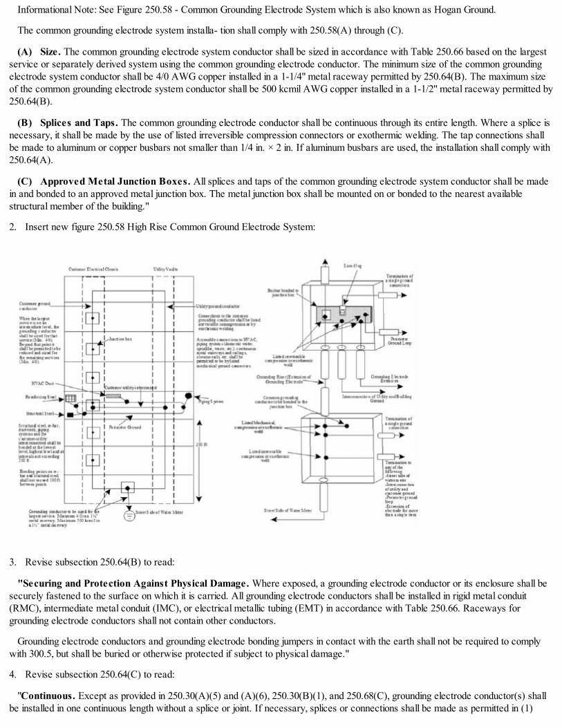
Informational Note: See Figure 250.58 - Common Grounding Electrode System which is also known as Hogan Ground.
The common grounding electrode system installa- tion shall comply with 250.58(A) through (C).
(A) Size. The common grounding electrode system conductor shall be sized in accordance with Table 250.66 based on the largestservice or separately derived system using the common grounding electrode conductor. The minimum size of the common groundingelectrode system conductor shall be 4/0 AWG copper installed in a 1-1/4" metal raceway permitted by 250.64(B). The maximum sizeof the common grounding electrode system conductor shall be 500 kcmil AWG copper installed in a 1-1/2" metal raceway permitted by250.64(B).
(B) Splices and Taps. The common grounding electrode conductor shall be continuous through its entire length. Where a splice isnecessary, it shall be made by the use of listed irreversible compression connectors or exothermic welding. The tap connections shallbe made to aluminum or copper busbars not smaller than 1/4 in. × 2 in. If aluminum busbars are used, the installation shall comply with250.64(A).
(C) Approved Metal Junction Boxes. All splices and taps of the common grounding electrode system conductor shall be madein and bonded to an approved metal junction box. The metal junction box shall be mounted on or bonded to the nearest availablestructural member of the building."
2. Insert new figure 250.58 High Rise Common Ground Electrode System:
3. Revise subsection 250.64(B) to read:
"Securing and Protection Against Physical Damage. Where exposed, a grounding electrode conductor or its enclosure shall besecurely fastened to the surface on which it is carried. All grounding electrode conductors shall be installed in rigid metal conduit(RMC), intermediate metal conduit (IMC), or electrical metallic tubing (EMT) in accordance with Table 250.66. Raceways forgrounding electrode conductors shall not contain other conductors.
Grounding electrode conductors and grounding electrode bonding jumpers in contact with the earth shall not be required to complywith 300.5, but shall be buried or otherwise protected if subject to physical damage."
4. Revise subsection 250.64(C) to read:
"Continuous. Except as provided in 250.30(A)(5) and (A)(6), 250.30(B)(1), and 250.68(C), grounding electrode conductor(s) shallbe installed in one continuous length without a splice or joint. If necessary, splices or connections shall be made as permitted in (1)

through (2):
(1) Splicing of the wire-type grounding electrode conductor shall be permitted only by irreversible compression-type connectorslisted as grounding and bonding equipment or by the exothermic welding process.
(2) Sections of busbars shall be permitted to be connected together to form a grounding electrode conductor."
5. Revise the second paragraph of subsection 250.64(D)(1):
"A grounding electrode conductor tap shall extend to the inside of each service disconnecting means enclosure. The groundingelectrode conductor taps shall be sized in accordance with 250.66 for the largest service-entrance conductor serving the individualenclosure. The tap conductors shall be connected to the common grounding electrode conductor by one of the following methods insuch a manner that the common grounding electrode conductor remains without a splice or joint:
(1) Exothermic welding.
(2) Connectors listed as grounding and bonding equipment.
(3) Connections to an aluminum or copper busbar not less than 1/4 in. × 2 in. The busbar shall be securely fastened in a metal boxand shall be installed in an accessible location. Connections shall be made by a listed connector or by the exothermic welding process.If aluminum busbars are used, the installation shall comply with 250.64(A)."
6. Revise subsection 250.64(F)(3) to read:
"Bonding jumper(s) from grounding electrode(s) shall be permitted to be connected to an aluminum or copper busbar not less than1/4 in. thick × 2 in. wide and of sufficient length to accommodate the number of terminations necessary for the installation. The busbarshall be securely fastened and shall be installed in a metal box and at an accessible location. Connections shall be made by a listedconnector or by the exothermic welding process. The grounding electrode conductor shall be permitted to be run to the busbar. Wherealuminum busbars are used, the installation shall comply with 250.64(A)."
7. Revise table 250.66 to read:
Size of LargestService- Entrance
Conductor orEquivalent for
Parallel Conductor(s)
Size of Grounding Electrode Conductor andConduit or Tubing
Copper Aluminum Copper Conduitor Tubing Aluminum Conduit
or Tubing
Up to 2 Up to 1/0 8 1/2 in. 6 1/2 in.Up to 1/0 Up to 3/0 6 1/2 in. 4 3/4 in.Up to 3/0 Up to 250 4 3/4 in. 2 3/4 in.Up to 350 Up to 500 2 3/4 in. 1/0 1 in.Up to 600 Up to 900 1/0 1 in. 3/0 1 in.Up to1100
Up to1750 2/0 1 in. 4/0 1 in.
Up to1300
Up to2000 3/0 1 in. 250 1-1/4 in.
Up to1700
Up to2400 4/0 1 in. 300 1-1/4 in.

Up to1700
Up to2800
250 1-1/4 in. 350 1-1/4 in.
Up to2000
Up to3200 300 1-1/4 in. 400 1-1/2 in.
Up to2400
Up to4000 350 1-1/4 in. 500 1-1/2 in.
Up to2800
Up to4800 400 1-1/2 in. 600 2 in.
Up to3200
Up to5600 500 1-1/2 in. 700 2 in.
(Added Coun. J. 9-6-17, p. 55278, Art. I, § 1; Amend Coun. J. 11-8-17, p. 59720, § 14)
14E-2-280 Surge arresters, over 1,000 volts.
The provisions of Article 280 of NFPA 70 are adopted by reference without modification.
(Added Coun. J. 9-6-17, p. 55278, Art. I, § 1)
14E-2-285 Surge protective devices (SPDs), 1,000 volts or less.
The provisions of Article 285 of NFPA 70 are adopted by reference without modification.
(Added Coun. J. 9-6-17, p. 55278, Art. I, § 1)
CHAPTER 14E-3GENERAL REQUIREMENTS FOR WIRING METHODS AND MATERIALS
14E-3-300 General requirements for wiring methods and materials.
14E-3-310 Conductors for general wiring.
14E-3-312 Cabinets, cutout boxes, and meter socket enclosures.
14E-3-314 Outlets, device, pull and junction boxes, conduit bodies; fittings; and handholeenclosures.
14E-3-320 Armored cable: Type AC.
14E-3-322 Flat cable assemblies: Type FC.
14E-3-324 Flat conductor cable: Type FCC.
14E-3-326 Integrated gas spacer cable: Type IGS.
14E-3-328 Medium voltage cable: Type MV.
14E-3-330 Metal-clad cable: Type MC.
14E-3-332 Mineral-insulated, metal-sheathed cable: Type MI.
14E-3-334 Nonmetallic-sheathed cable: Types NM, NMC, and NMS.
14E-3-336 Power and control tray cable: Type TC.
14E-3-338 Service-entrance cable: Type SE and USE.
14E-3-340 Underground feeder and branch- circuit cable: Type UF.
14E-3-342 Intermediate metal conduit: Type IMC.

14E-3-344 Rigid metal conduit: Type RMC.
14E-3-348 Flexible metal conduit: Type FMC.
14E-3-350 Liquidtight flexible metal conduit: Type LFMC.
14E-3-352 Rigid polyvinyl chloride conduit: Type PVC.
14E-3-353 High density polyethylene conduit: Type HDPE conduit.
14E-3-354 Nonmetallic underground conduit with conductors: Type NUCC.
14E-3-355 Reinforced thermosetting resin conduit: Type RTRC.
14E-3-356 Liquidtight flexible nonmetallic conduit: Type LFNC.
14E-3-358 Electrical metallic tubing: Type EMT.
14E-3-360 Flexible metallic tubing: Type FMT.
14E-3-362 Electrical nonmetallic tubing: Type ENT.
14E-3-366 Metallic auxiliary gutters.
14E-3-368 Busways.
14E-3-370 Cablebus.
14E-3-372 Cellular concrete floor raceways.
14E-3-374 Cellular metal floor raceways.
14E-3-376 Metal wireways.
14E-3-378 Nonmetallic wireways.
14E-3-380 Multi-outlet assembly.
14E-3-382 Nonmetallic extensions.
14E-3-384 Strut-type channel raceway.
14E-3-386 Surface metal raceways.
14E-3-388 Surface nonmetallic raceways.
14E-3-390 Underfloor raceways.
14E-3-392 Cable trays.
14E-3-393 Low-voltage suspended ceiling power distribution systems.
14E-3-394 Concealed knob-and-tube wiring.
14E-3-396 Messenger-supported wiring.
14E-3-398 Open wiring on insulators.
14E-3-399 Outdoor overhead conductors over 1,000 volts.
14E-3-300 General requirements for wiring methods and materials.
The provisions of Article 300 of NFPA 70 are adopted by reference with the following modification:
1. Revise section 300.22 to read:
"Wiring in Ducts Not Used for Air-Handling, Fabricated Ducts for Environmental Air, Plenums, and Other Spaces forEnvironmental Air (Plenums). The provisions of this section apply to the installation and uses of electric wiring and equipment in

ducts used for dust, loose stock, or vapor material; ducts specifically fabricated for environmental air; and other spaces used forenvironmental air (plenums).
Informational Note: See Article 424, Part VI, for duct heaters.
(A) Ducts for Dust, Loose Stock, or Vapor Removal. No wiring systems of any type shall be installed in ducts used totransport dust, loose stock, or flammable vapors. No wiring system of any type shall be installed in any duct, or shaft containing onlysuch ducts, used for vapor removal or for ventilation of commercial-type cooking equipment.
(B) Ducts Specifically Fabricated for Environmental Air. Equipment, devices, and the wiring methods specified in this sectionshall be permitted within such ducts only if they are necessary for the direct action upon, or sensing of, the contained air. Whereequipment or devices are installed and illumination is necessary to facilitate maintenance and repair, enclosed gasketed-type luminairesshall be required.
In ducts specifically fabricated to for environmental air, only the wiring methods consisting of the following shall be permitted:
(1) Conductors or cables installed in electrical metallic tubing with gland nut type fittings, intermediate metal conduit or galvanizedrigid metal conduit
(2) Type MI Cable as permitted in Article 332
(3) Type MC Cable employing a smooth or corrugated impervious metal sheath without an overall nonmetallic covering, aspermitted in Article 330
(4) Flexible metallic tubing as permitted in Article 360
(5) Liquidtight flexible metal conduit in lengths not to exceed 1.22 m (4 ft), to connect physically adjustable equipment anddevices permitted to be in these ducts.
(C) Other Space Used for Environmental Air (Plenums). This section shall apply to spaces not specifically fabricated forenvironmental air-handling purposes but used for air-handling purposes as a plenum. This section shall not apply to habitable rooms orareas of buildings, the prime purpose of which is not air handling.
Informational Note: The space over a hung ceiling used for environmental air-handling purposes and the space below a raised floorused for environmental air-handling purposes are examples of the type of other space to which this section applies.
Exception: This section shall not apply to the joist or stud spaces of dwelling units where the wiring passes through suchspaces perpendicular to the long dimension of such spaces.
(1) Wiring Methods. The wiring methods for such other space shall be limited to the following:
(a) Conductors or cables installed in electrical metallic tubing with gland nut type fittings, intermediate metal conduit orgalvanized rigid metal conduit
(b) Type MI Cable as permitted in Article 332
(c) Type MC Cable employing a smooth or corrugated impervious metal sheath without an overall nonmetallic covering aspermitted in Article 330
(d) Flexible metallic tubing as permitted in Article 360
(e) Liquidtight flexible metal conduit in lengths not to exceed 1.83 m (6 ft), to connect physically adjustable equipment anddevices, other than lighting fixtures, permitted to be in these spaces.
(2) Luminaires and Electric Equipment. Electric equipment with a metal enclosure and no direct openings to the air space,and associated wiring material suitable for the ambient temperature shall be permitted to be installed in such other space unlessprohibited elsewhere in this Code. Boxes shall have no holes and shall be provided with gasketed covers. Luminaires meeting thesecriteria and intended for use in this space shall be marked CCEA.
Informational Note 1: Criteria for CCEA (City of Chicago Environmental Air) may be obtained from Underwriters Laboratories.
Informational Note 2: This requirement is not intended to limit recessed fixtures that are constructed with tight seams and joints.Where so constructed no additional gasketing or sealing is required.
Exception: Integral fan systems specifically identified for such use.

(D) Information Technology Equipment. Electric wiring in air-handling areas beneath raised floors for information technologyequipment shall be in accordance with 300.22(C) and Article 645."
(Added Coun. J. 9-6-17, p. 55278, Art. I, § 1)
14E-3-310 Conductors for general wiring.
The provisions of Article 310 of NFPA 70 are adopted by reference with the following modifications:
1. Insert the following language immediately before informational note no. 1 in subsection 310.15(B)(3)(a):
"No more than nine current-carrying conductors shall be permitted to be installed in a raceway."
2. Revise table 310.15(B)(3)(a) to read:
Number ofCurrent-Carrying
Conductors
Percent of Values in Table310.15(B)(16) throughTable 310.15(B)(19) asAdjusted for Ambient
Temperature if Necessary
4-6 807-9 70
(Added Coun. J. 9-6-17, p. 55278, Art. I, § 1)
14E-3-312 Cabinets, cutout boxes, and meter socket enclosures.
The provisions of Article 312 of NFPA 70 are adopted by reference without modification.
(Added Coun. J. 9-6-17, p. 55278, Art. I, § 1)
14E-3-314 Outlets, device, pull and junction boxes, conduit bodies; fittings; and handhole enclosures.
The provisions of Article 314 of NFPA 70 are adopted by reference without modification.
(Added Coun. J. 9-6-17, p. 55278, Art. I, § 1)
14E-3-320 Armored cable: Type AC.
The provisions of Article 320 of NFPA 70 are adopted by reference with the following modifications:
1. Revise section 320.10 to read:
"Uses Permitted. Type AC cable shall be permitted to be installed as specified in 320.10(A) or (B).
(A) Existing Installations. Except where otherwise specified in this Code and where not subject to physical damage, listed TypeAC cable with listed fittings and not exceeding 7.62 m (25 ft) in length between junction boxes shall be permitted to be installed forbranch circuits in concealed work fished into existing walls, partitions, floors, or hard surface ceilings where other work does notrequire or include removal of the existing finished surface.
(B) Exposed Work. For exposed work only under the following conditions:
(1) In lengths not more than 1.83 m (6 ft), at terminations where flexibility is necessary;
(2) In lengths not more than 1.83 m (6 ft) in accessible, but not habitable, attics and roof spaces where installed in accordancewith 320.12;
(3) In lengths not greater than 1.83 m (6 ft), below the basement ceiling joists where it is necessary to connect a cabinet orjunction box."

2. Revise section 320.12 to read:
"Uses Not Permitted. Type AC cable shall not be used for any installation not permitted in 320.10."
(Added Coun. J. 9-6-17, p. 55278, Art. I, § 1)
14E-3-322 Flat cable assemblies: Type FC.
The provisions of Article 322 of NFPA 70 are not adopted.
(Added Coun. J. 9-6-17, p. 55278, Art. I, § 1)
14E-3-324 Flat conductor cable: Type FCC.
The provisions of Article 324 of NFPA 70 are adopted by reference without modification.
(Added Coun. J. 9-6-17, p. 55278, Art. I, § 1)
14E-3-326 Integrated gas spacer cable: Type IGS.
The provisions of Article 326 of NFPA 70 are not adopted.
(Added Coun. J. 9-6-17, p. 55278, Art. I, § 1)
14E-3-328 Medium voltage cable: Type MV.
The provisions of Article 328 of NFPA 70 are adopted by reference without modification.
(Added Coun. J. 9-6-17, p. 55278, Art. I, § 1)
14E-3-330 Metal-clad cable: Type MC.
The provisions of Article 330 of NFPA 70 are adopted by reference with the following modifications:
1. Revise section 330.10 to read:
"Uses Permitted.
(A) Existing Installations. Except where otherwise specified in this Code and where not subject to physical damage, listed TypeMC cable with listed fittings and not exceeding 7.62 m (25 ft) in length between junction boxes shall be permitted for branch circuits inconcealed work fished into existing walls, partitions, floors, or hard surface ceilings where other work does not require or includeremoval of the existing finished surface.
(B) Exposed Work. For exposed work only under the following conditions:
(1) In lengths not more than 1.83 m (6 ft), at terminations where flexibility is necessary;
(2) In lengths not greater than 1.83 m (6 ft) in accessible, but not habitable, attics and roof spaces where installed in accordancewith 320.23;
(3) In lengths not greater than 1.83 m (6 ft), below the basement ceiling joists where it is necessary to connect a cabinet orjunction box."
2. Revise section 330.12 to read:
"Uses Not Permitted. Type MC cable shall not be used for any installation not permitted in 330.10."
(Added Coun. J. 9-6-17, p. 55278, Art. I, § 1)
14E-3-332 Mineral-insulated, metal-sheathed cable: Type MI.
The provisions of Article 332 of NFPA 70 are adopted by reference without modification.
(Added Coun. J. 9-6-17, p. 55278, Art. I, § 1)
14E-3-334 Nonmetallic-sheathed cable: Types NM, NMC, and NMS.
The provisions of Article 334 of NFPA 70 are adopted by reference with the following modifications:

1. Revise section 334.10 to read:
"Uses Permitted. Type NM and Type NMC cables shall be permitted to be used in the following:
(1) Temporary wiring for branch circuits as permitted in 590.4(C)
(2) Temporary wiring as permitted for feeders as permitted in 590.4(B)
(3) Limited extensions to knob-and-tube lighting or appliance branch circuits in existing dwelling units in buildings not exceedingthree stories in height."
2. Revise section 334.12 to read:
"Uses Not Permitted.
(A) Types NM, and NMC. Types NM and NMC cables shall not be used for any installation not permitted in 334.10.
(B) Type NMS. Type NMS cables shall not be used."
(Added Coun. J. 9-6-17, p. 55278, Art. I, § 1)
14E-3-336 Power and control tray cable: Type TC.
The provisions of Article 336 of NFPA 70 are adopted by reference with the following modifications:
1. Revise subsection 336.10, item (1) to read:
"For control and signal circuits."
2. Delete subsections 336.10, items (6) through (10).
3. Revise section 336.12 to read:
"Uses Not Permitted. Type TC tray cable shall not be installed or used as follows:
(1) Installed where it will be exposed to physical damage
(2) Installed outside a raceway or cable tray system
(3) Used where exposed to direct rays of the sun, unless identified as sunlight resistant
(4) Direct buried
(5) Required fire alarm systems
(6) In health care facilities, any patient communication or monitoring system"
(Added Coun. J. 9-6-17, p. 55278, Art. I, § 1; Amend Coun. J. 11-8-17, p. 59720, § 15)
14E-3-338 Service-entrance cable: Type SE and USE.
The provisions of Article 338 of NFPA 70 are adopted by reference with the following modifications:
1. Revise section 338.10 to read:
"Uses Permitted. For existing buildings of non- transient residential occupancy containing not more than three dwelling units:
(A) Service-Entrance Conductors. Service- entrance cable shall be permitted to be used as service- entrance conductors.
(B) Branch Circuits.
(1) Branch Circuit Conductors. Type SE service-entrance cable shall be permitted for circuit wiring for electric ranges, electrichot water heaters, and electric clothes dryers.
(2) Grounded Conductor Insulated. Type SE service-entrance cables shall be permitted in wiring systems where all of the circuitconductors of the cable are of the thermoset or thermoplastic type.
(3) Use of Uninsulated Conductor. Type SE service-entrance cable without individual insulation on the grounded conductor shall

not be permitted for branch circuit wiring.
(4) Temperature Limitations. Type SE service-entrance cable used to supply appliances shall not be subject to conductortemperatures in excess of the temperature specified for the type of insulation involved.
(5) Installation Methods for Cables. Cables shall be installed in accordance with (a) through (d) as listed below.
(a) Cable shall not be spliced, but shall be installed without interruption to the outlet
(b) Installation shall have approved and listed fittings
(c) In exposed installations, the cable shall follow closely follow the surface and be fastened at intervals not exceeding 450 mm(18 in.).
(d) In exterior installations, the cable shall be installed in a workman like manner in straight lines and a drip loop shall beprovided"
2. Revise section 338.12 to read:
"Uses Not Permitted. Type SE and Type USE shall not be used for any installation not permitted in 338.10."
(Added Coun. J. 9-6-17, p. 55278, Art. I, § 1; Amend Coun. J. 11-8-17, p. 59720, § 16)
14E-3-340 Underground feeder and branch-circuit cable: Type UF.
The provisions of Article 340 of NFPA 70 are adopted by reference with the following modification:
1. Revise section 340.10 to read:
"Uses Permitted. Listed Type UF cable shall be permitted as follows:
(1) For use underground, including direct burial in the earth. For underground requirements, see 300.5.
(2) As single-conductor cables. Where installed as single- conductor cables, all conductors of the feeder grounded conductor orbranch circuit, including the grounded conductor and equipment grounding conductor, if any, shall be installed in accordance with 300.3.
(3) For solar photovoltaic systems in accordance with 690.31.
(4) As single-conductor cables as the non-heating leads for heating cables as provided in 424.43.
Informational Note: See 310.15(A)(3) for temperature limitation of conductors."
(Added Coun. J. 9-6-17, p. 55278, Art. I, § 1)
14E-3-342 Intermediate metal conduit: Type IMC.
The provisions of Article 342 of NFPA 70 are adopted by reference without modification.
(Added Coun. J. 9-6-17, p. 55278, Art. I, § 1)
14E-3-344 Rigid metal conduit: Type RMC.
The provisions of Article 344 of NFPA 70 are adopted by reference without modification.
(Added Coun. J. 9-6-17, p. 55278, Art. I, § 1)
14E-3-348 Flexible metal conduit: Type FMC.
The provisions of Article 348 of NFPA 70 are adopted by reference with the following modifications:
1. Revise section 348.10 to read:
"Uses Permitted. FMC shall be permitted to be used:
(1) For the connection of motors or recessed luminaires
(2) In lengths not exceeding 7.62 m (25 ft) between junction boxes for branch circuits in concealed work fished into existing walls,partitions, floors, or hard surface ceilings where other work does not require or include removal of the existing finished surface

(3) For required flexibility at the termination of conduit runs."
2. Insert new subsections 348.12(8) and (9) to read:
"(8) In lengths exceeding 1.83 m (6 ft) except where fished in existing construction
(9) Where exposed below the first floor except 1.83 m (6 ft) of any run shall be permitted to extend below the basement ceiling toconnect to a cabinet, outlet box or junction box."
(Added Coun. J. 9-6-17, p. 55278, Art. I, § 1)
14E-3-350 Liquidtight flexible metal conduit: Type LFMC.
The provisions of Article 350 of NFPA 70 are adopted by reference with the following modifications:
1. Delete subsection 350.10(3).
2. Insert new subsections 350.10(3) through (5) to read:
"(3) For the connection of motors and recessed luminaires in a non-plenum ceiling
(4) In lengths not exceeding 1.8 m (6 ft) between junction boxes for branch circuits in concealed work fished into existing walls,partitions, floors, or hard surface ceilings where other work does not require or include removal of the existing finished surface
(5) For required flexibility at the terminations of conduit runs."
3. Insert new subsections 350.12(3) through (7) to read:
"(3) In hoistways, other than as permitted in 620.21(A)(1)
(4) In storage battery rooms
(5) In any hazardous (classified) location except as permitted by other articles in this Code
(6) Where exposed to materials having a deteriorating effect on the installed conductors, such as oil or gasoline
(7) Underground or embedded in poured concrete or aggregate"
(Added Coun. J. 9-6-17, p. 55278, Art. I, § 1)
14E-3-352 Rigid polyvinyl chloride conduit: Type PVC.
The provisions of Article 352 of NFPA 70 are adopted by reference with the following modification:
1. Revise section 352.10 to read:
"Uses Permitted. The use of PVC conduit shall be permitted in accordance with 352.10(A) through (F).
Informational Note: Extreme cold may cause some nonmetallic conduits to become brittle and, therefore, more susceptible todamage from physical contact.
(A) Corrosive Influences. PVC conduit shall be permitted in locations subject to severe corrosive influences as covered in 300.6and where subject to chemicals for which the materials are specifically approved.
(B) Cinders. PVC conduit shall be permitted in cinder fill.
(C) Wet Locations. PVC conduit shall be permitted in portions of dairies, laundries, canneries, or other wet locations, and inlocations where walls are frequently washed, the entire conduit system, including boxes and fittings used therewith, shall be installedand equipped so as to prevent water from entering the conduit. All supports, bolts, straps screws, and so forth, shall be of corrosion-resistant materials or be protected against corrosion by approved corrosion-resistant materials.
(D) Underground Installations. For underground installations, PVC conduit shall be permitted for direct burial and undergroundencased in concrete. See 300.5 and 300.50.
(E) Support of Conduit Bodies. PVC conduit shall be permitted to support nonmetallic conduit bodies not larger than the largesttrade size of an entering raceway. These conduit bodies shall not support luminaires or other equipment and shall not contain devicesother than splicing devices as permitted by 110.14(B) and 314.16(C)(2).

(F) Insulation Temperature Limitations. Conductors or cables rated at a temperature higher than the listed temperature ratingof PVC conduit shall be permitted to be installed in PVC conduit, provided the conductors or cables are not operated at a temperaturehigher than the listed temperature rating of the PVC conduit."
(Added Coun. J. 9-6-17, p. 55278, Art. I, § 1; Amend Coun. J. 11-8-17, p. 59720, § 17)
14E-3-353 High density polyethylene conduit: Type HDPE conduit.
The provisions of Article 353 of NFPA 70 are adopted by reference without modification.
(Added Coun. J. 9-6-17, p. 55278, Art. I, § 1)
14E-3-354 Nonmetallic underground conduit with conductors: Type NUCC.
The provisions of Article 354 of NFPA 70 are adopted by reference without modification.
(Added Coun. J. 9-6-17, p. 55278, Art. I, § 1)
14E-3-355 Reinforced thermosetting resin conduit: Type RTRC.
The provisions of Article 355 of NFPA 70 are adopted by reference with the following modification:
1. Revise section 355.10 to read:
"Uses Permitted. The use of RTRC shall be permitted in accordance with 355.10(A) through (F).
(A) Corrosive Influences. RTRC shall be permitted in locations subject to severe corrosive influences as covered in 300.6 andwhere subject to chemicals for which the materials are specifically approved.
(B) Cinders. RTRC shall be permitted in cinder fill.
(C) Wet Locations. RTRC shall be permitted in portions of dairies, laundries, canneries, or other wet locations, and in locationswhere walls are frequently washed, the entire conduit system, including boxes and fittings used therewith, shall be installed andequipped so as to prevent water from entering the conduit. All supports, bolts, straps screws, and so forth, shall be of corrosion-resistant materials or be protected against corrosion by approved corrosion-resistant materials.
(D) Underground Installations. For underground installations, see 300.5 and 300.50.
(E) Support of Conduit Bodies. RTRC shall be permitted to support nonmetallic conduit bodies not larger than the largest tradesize of an entering raceway. These conduit bodies shall not support luminaires or other equipment and shall not contain devices otherthan splicing devices as permitted by 110.14(B) and 314.16(C)(2).
(F) Insulation Temperature Limitations. Conductors or cables rated at a temperature higher than the listed temperature ratingof RTRC conduit shall be permitted to be installed in PVC conduit, provided the conductors or cables are not operated at atemperature higher than the listed temperature rating of the RTRC conduit."
(Added Coun. J. 9-6-17, p. 55278, Art. I, § 1; Amend Coun. J. 11-8-17, p. 59720, § 18)
14E-3-356 Liquidtight flexible nonmetallic conduit: Type LFNC.
The provisions of Article 356 of NFPA 70 are not adopted.
(Added Coun. J. 9-6-17, p. 55278, Art. I, § 1)
14E-3-358 Electrical metallic tubing: Type EMT.
The provisions of Article 358 of NFPA 70 are adopted by reference with the following modification:
1. Insert the following language at the end of section 258.12:
"(3) For enclosing service entrance conductors"
(Added Coun. J. 9-6-17, p. 55278, Art. I, § 1)
14E-3-360 Flexible metallic tubing: Type FMT.

The provisions of Article 360 of NFPA 70 are adopted by reference with the following modifications:
1. Revise subsections 360.10(1) through (4) to read:
"(1) Branch circuits not exceeding 20 amperes and 300 volts to ground
(2) As permitted in 300.22(C)
(3) Connection between a junction box and a single luminaire
(4) Connection between a junction box and speakers or similar equipment requiring flexibility"
2. Insert new subsection 360.12(7) to read:
"(7) Other than as specifically permitted in 360.10"
(Added Coun. J. 9-6-17, p. 55278, Art. I, § 1)
14E-3-362 Electrical nonmetallic tubing: Type ENT.
The provisions of Article 362 of NFPA 70 are not adopted.
(Added Coun. J. 9-6-17, p. 55278, Art. I, § 1)
14E-3-366 Metallic auxiliary gutters.
The provisions of Article 366 of NFPA 70 are adopted by reference with the following modifications:
1. Revise the title of Article 366 to read "Metallic Auxiliary Gutters."
2. Revise section 366.1 to read:
"Scope. This article covers the use, installation, and construction requirements of metal auxiliary gutters and associated fittings."
3. Revise section 366.2 by deleting the definition of "Nonmetallic Auxiliary Gutter."
4. Delete section 366.6.
5. Delete subsection 366.10(B).
6. Delete subsection 366.22(B).
7. Delete subsection 366.23(B).
8. Delete subsection 366.30(B).
9. Delete section 366.120.
(Added Coun. J. 9-6-17, p. 55278, Art. I, § 1)
14E-3-368 Busways.
The provisions of Article 368 of NFPA 70 are adopted by reference with the following modifications:
1. Revise section 368.12, by adding a new subsection (F) to read:
"(F) Sprinklers. In rooms or areas where an automatic sprinkler system is installed which, when activated, would cause water tocome into contact with the busway.
Exception: Busway that is listed as weatherproof or raintight shall be permitted in locations with sprinkler protection."
2. Revise subsection 368.56, by deleting items 1, 2, 8, 9, 10, 12, 14, and 16.
(Added Coun. J. 9-6-17, p. 55278, Art. I, § 1; Amend Coun. J. 11-8-17, p. 59720, § 19)
14E-3-370 Cablebus.
The provisions of Article 370 of NFPA 70 are adopted by reference without modification.

(Added Coun. J. 9-6-17, p. 55278, Art. I, § 1)
14E-3-372 Cellular concrete floor raceways.
The provisions of Article 372 of NFPA 70 are not adopted.
(Added Coun. J. 9-6-17, p. 55278, Art. I, § 1)
14E-3-374 Cellular metal floor raceways.
The provisions of Article 374 of NFPA 70 are adopted by reference without modification.
(Added Coun. J. 9-6-17, p. 55278, Art. I, § 1)
14E-3-376 Metal wireways.
The provisions of Article 376 of NFPA 70 are adopted by reference with the following modification:
1. Revise section 376.12 by inserting new items (3) and (4) to read:
"(3) For service entrance conductors
(4) Above suspended ceilings"
(Added Coun. J. 9-6-17, p. 55278, Art. I, § 1)
14E-3-378 Nonmetallic wireways.
The provisions of Article 378 of NFPA 70 are not adopted.
(Added Coun. J. 9-6-17, p. 55278, Art. I, § 1)
14E-3-380 Multi-outlet assembly.
The provisions of Article 380 of NFPA 70 are adopted by reference with the following modification:
1. Revise section 380.12 item (3) to read:
"(3) Where the voltage is 300 volts or more between conductors"
(Added Coun. J. 9-6-17, p. 55278, Art. I, § 1)
14E-3-382 Nonmetallic extensions.
The provisions of Article 382 of NFPA 70 are not adopted.
(Added Coun. J. 9-6-17, p. 55278, Art. I, § 1)
14E-3-384 Strut-type channel raceway.
The provisions of Article 384 of NFPA 70 are adopted by reference with the following modification:
1. Revise section 384.10 by inserting new item (8) to read:
"(8) Where the voltage is 600 volts or less."
(Added Coun. J. 9-6-17, p. 55278, Art. I, § 1)
14E-3-386 Surface metal raceways.
The provisions of Article 386 of NFPA 70 are adopted by reference with the following modification:
1. Revise section 386.12 by inserting new item (6) to read:
"(6) In any hazardous (classified) location"
(Added Coun. J. 9-6-17, p. 55278, Art. I, § 1)
14E-3-388 Surface nonmetallic raceways.

The provisions of Article 388 of NFPA 70 are not adopted.
(Added Coun. J. 9-6-17, p. 55278, Art. I, § 1)
14E-3-390 Underfloor raceways.
The provisions of Article 390 of NFPA 70 are adopted by reference without modification.
(Added Coun. J. 9-6-17, p. 55278, Art. I, § 1)
14E-3-392 Cable trays.
The provisions of Article 392 of NFPA 70 are adopted by reference with the following modifications:
1. Revise the informational note to section 392.1 to read:
"Informational Note: For further information on cable trays, see ANSI/NEMA-VE 1-2009, Metal Cable Tray Systems; andNECA/NEMA 105-2015, Standard for Installing Metal Cable Tray Systems."
2. Revise section 392.10, including table 392.10(A), to read:
"(A) Uses Permitted. Metal cable tray shall be permitted to be used as:
(1) A support system for ac or dc power conductors 50 volts or less
(2) For communications circuits, control circuits, and signaling circuits.
(3) A support system for the wiring methods in Table 392.10(A), under the conditions described in their respective articles andsections.
Table 392.10(A) Wiring Methods
Wiring Method Article/Chapter
Electrical metallic tubing: TypeEMT 358
Instrumentation tray cable: TypeITC 727
Intermediate metal conduit: TypeIMC 342
Mineral-insulated, metal-sheathedcable: Type MI 332
Multipurpose and communicationscables Chapter 8
Optical fiber cables 770Other factory-assembled,multiconductor control, signal, orpower cables that are specificallyapproved for installation in cabletraysPower-limited tray cable 725Rigid metal conduit: Type RMC 344

(B) Hazardous (Classified) Locations. Cable trays in hazardous (classified) locations shall contain only the cable types andraceways permitted by other articles in this Code."
3. Revise subsection 392.12 to read:
"Uses Not Permitted. Cable tray systems shall not be used in the following:
(1) Hoistways
(2) Where subject to severe physical damage
(3) Ducts and other spaces for environmental air subject (plenums) subject to 300.22
(4) As a support system for ac or dc power conductors over 50 volts"
(Added Coun. J. 9-6-17, p. 55278, Art. I, § 1)
14E-3-393 Low-voltage suspended ceiling power distribution systems.
The provisions of Article 393 of NFPA 70 are not adopted.
(Added Coun. J. 9-6-17, p. 55278, Art. I, § 1)
14E-3-394 Concealed knob-and-tube wiring.
The provisions of Article 394 of NFPA 70 are adopted by reference without modification.
(Added Coun. J. 9-6-17, p. 55278, Art. I, § 1)
14E-3-396 Messenger-supported wiring.
The provisions of Article 396 of NFPA 70 are adopted by reference without modification.
(Added Coun. J. 9-6-17, p. 55278, Art. I, § 1)
14E-3-398 Open wiring on insulators.
The provisions of Article 398 of NFPA 70 are not adopted.
(Added Coun. J. 9-6-17, p. 55278, Art. I, § 1)
14E-3-399 Outdoor overhead conductors over 1,000 volts.
The provisions of Article 399 of NFPA 70 are adopted by reference without modification.
(Added Coun. J. 9-6-17, p. 55278, Art. I, § 1)
CHAPTER 14E-4EQUIPMENT FOR GENERAL USE
14E-4-400 Flexible cords and cables.
14E-4-402 Fixture wires.
14E-4-404 Switches.
14E-4-406 Receptacles, cord connectors, and attachment plugs (caps).
14E-4-408 Switchboard, switchgear, and panelboards.
14E-4-409 Industrial control panels.
14E-4-410 Luminaires, lampholders, and lamps.
14E-4-411 Low voltage lighting.
14E-4-422 Appliances.

14E-4-424 Fixed electric space-heating equipment.
14E-4-425 Fixed resistance and electrode industrial process heating equipment.
14E-4-426 Fixed outdoor electric de-icing and snow-melting equipment.
14E-4-427 Fixed electric heating equipment for pipeline and vessels.
14E-4-430 Motors, motor circuits, and controllers.
14E-4-440 Air-conditioning and refrigeration equipment.
14E-4-445 Generators.
14E-4-450 Transformers and transformer vaults (including secondary ties).
14E-4-455 Phase converters.
14E-4-460 Capacitors.
14E-4-470 Resistors and reactors.
14E-4-480 Storage batteries.
14E-4-490 Equipment over 1,000 volts, nominal.
14E-4-400 Flexible cords and cables.
The provisions of Article 400 of NFPA 70 are adopted by reference without modification.
(Added Coun. J. 9-6-17, p. 55278, Art. I, § 1)
14E-4-402 Fixture wires.
The provisions of Article 402 of NFPA 70 are adopted by reference without modification.
(Added Coun. J. 9-6-17, p. 55278, Art. I, § 1)
14E-4-404 Switches.
The provisions of Article 404 of NFPA 70 are adopted by reference with the following modification:
1. Revise subsection 404.14(D) to read:
"Voltage. Snap switches shall not be used for the control of greater than 150V to ground circuits."
(Added Coun. J. 9-6-17, p. 55278, Art. I, § 1)
14E-4-406 Receptacles, cord connectors, and attachment plugs (caps).
The provisions of Article 406 of NFPA 70 are adopted by reference with the following modification:
1. Revise section 406.3, by deleting subsection (D)(2) and the subsequent exception.
(Added Coun. J. 9-6-17, p. 55278, Art. I, § 1; Amend Coun. J. 11-8-17, p. 59720, § 20)
14E-4-408 Switchboard, switchgear, and panelboards.
The provisions of Article 408 of NFPA 70 are adopted by reference with the following modification:
1, Insert new section 408.11 to read:
"408.11 Special Services
(A) General. A special service switchboard or switchgear is defined as a switchboard or switchgear with a single disconnectingmeans having a frame rating in excess of 1200 amperes, or a sequence service switchboard where the sum of the frame sizes exceeds1200 amperes. The following installation and construction shall apply to special service switchboards.
Informational Note: See 230.70 for permissible location(s) of the service disconnecting means.
(B) Drawing Submittal. The switchboard manufacturer who builds or assembles the special service equipment shall submit threesets of detailed drawings of the proposed equipment to the utility supply company. Upon acceptance, the utility shall retain one copy,stamp their acceptance and the available fault current, and forward them to the authority having jurisdiction.
The authority having jurisdiction shall review the drawings and notify the applicant of any changes, corrections, additions, ordeletions required for approval. No switchboard shall be delivered or installed until the switchboard manufacturer has receivedapproval from the authority having jurisdiction.
(C) Switchboard Rooms. The special service equipment shall be installed in a dedicated room of fire- resistant construction,accessible only to qualified persons. Where subject to possible flooding, such as below grade, sump pumps shall be provided and floormounted switchboards shall be installed on a concrete pad a minimum of 102 mm (4 in.) above the nominal floor level.
Switchboard rooms containing equipment rated 3000 amperes or greater shall have two or more means of egress. Egresspersonnel doors shall be equipped with suitable listed hardware to provide egress from the room.
(D) Ability to Withstand Fault Current. Such special service equipment shall be so designed, constructed, and assembled that itis capable of withstanding and interrupting the available fault current without damage to itself or its related equipment.
(E) Identification. All service and feeder disconnecting means shall be prominently identified by permanent means in accordancewith 110.22.
(F) Barriers. All unprotected service bus shall be barriered or insulated to isolate the service busbars and terminals from theremainder of the switchboard. The exposed live or unprotected bus necessary to connect the line side of each switch shall bepermitted to be un- isolated. The utility current transformers shall be in a barriered section conforming to the utility supply companyrequirements.
(G) Disconnecting Link. A disconnecting link shall be provided on the line side of the service switch or circuit breaker in thegrounded conductor. Such link shall be located in the service switch or circuit breaker enclosure. In sequence switchboards, whereeach switch is permitted to have its own neutral disconnecting link, the location of the disconnecting link shall be provided on theswitchboard cover.
(H) Bus Ampacity.
(1) Service entrance conductors and bus work on the line side of the service entrance switch(es) or circuit breaker(s) shall havean ampacity sufficient to carry the load supplied but shall not be less than 80% of the total rating of the service switch(es) or the framesize of the circuit breaker or breakers.
(2) When 100% rated switches or circuit breakers are used as the service disconnecting means, service entrance conductors andbus work shall have a rating of not less than 100% of the total rating of the service switch(es).
(3) Each switch or circuit breaker of the assembly shall be supplied by bus having an ampacity equal to the full rating of theswitch or circuit breaker.
(I) Smallest Size Switch. Switches or circuit breakers need not be the same size; however, no switch or circuit breaker ispermitted to be smaller than 400 amperes.
Exception No. 1: For a small emergency lighting load a switch sufficient in size for the load shall be permitted to be used. Suchswitch shall be mounted in the switchboard and shall be considered one of the six service disconnects.
Exception No. 2: On a sequence switchboard where the sum of the switches does not exceed 2400 amperes, 200 amperes shall bethe minimum frame size.
(J) Maximum Electrical AC Service Size. The ampacity of any switchboard, switchgear or electrical ac service shall be limitedto 4000 amperes. The maximum rating of any service disconnecting means shall be 3000 amperes. In a sequence service, which is aservice with up to six disconnects, the sum of the disconnecting means shall not exceed 5000 amperes and no single disconnect shallexceed 3000 amperes. If the capacity requirements of an installation exceeds 4000 amperes, provisions for two or more electrical acservices shall be made.
(K) Complete Metal Enclosure. The switchboard or switchgear shall have a complete metal enclosure including bottom plates.
Exception: The bottom plates shall be permitted to be omitted when the switchboard is installed in a dedicated room of fire-

resistant construction on a concrete pad where there is no opening between the walls of the switchboard and the pad. The conduitentries shall conform to 408.5 and shall be bonded as required by 250.94.
(L) Conduit Entries . All conduit entries to the ac service switchboard or switchgear shall have bonding bushings and their strapsshall terminate on the bonding bus. Conduit entries to the switchboard or switchgear enclosure shall not be made within 10 in. of anylive switchboard bus. Service entrance raceways shall enter the switchboard only in the service switch, cable transition, or currenttransformer sections. No other conductors shall pass through these sections. Feeder conduits and conductors shall terminate in theswitchboard section from which they are supplied.
(M) Header Boxes . Header boxes shall contain not more than 30 conductors at any cross section and shall comply with314.28(B). All header boxes shall be of the same construction as the switchboard.
(N) Bottom Boxes.
(1) Concrete gutters or trenches under switchboards or switchgear shall not be permitted.
(2) An under-switchboard or switchgear trench or gutter, in a dry location, lined with metal of the proper gauge to form anapproved bottom box, and which is properly bonded to the switchboard or switchgear to form a complete enclosure shall be permitted.All conduit entries to this bottom box shall comply with (l) of this subsection.
Informational Note: A concrete slab in contact with the earth, or on the lowest level of a building is not a dry location.
(3) Where a bottom box is allowed in a wet location, the installation is subject to special review by the authority havingjurisdiction. Complete drawings of the installation shall be submitted with the switchboard submittal, along with a request for specialpermission. A means to drain any accumulated moisture shall be provided.
(O) Maintenance. Required maintenance for special service equipment shall conform to 408.4."
14E-4-409 Industrial control panels.
The provisions of Article 409 of NFPA 70 are adopted by reference without modification.
(Added Coun. J. 9-6-17, p. 55278, Art. I, § 1)
14E-4-410 Luminaires, lampholders, and lamps.
The provisions of Article 410 of NFPA 70 are adopted by reference with the following modifications:
1. Revise subsection 410.24(A) to read:
"Independent of the Outlet Box. Electric- discharge and LED luminaires supported independently of the outlet box shall beconnected to the branch circuit through metal raceway, Type MC cable, Type AC cable, Type MI cable, or by flexible cord aspermitted in 410.62(B) or 410.62(C)."
2. Revise subsection 410.62(C)(1) to read:
"Cord-Connected Installation. A luminaire or a listed assembly in compliance with either condition (a) or (b) shall be permitted tobe cord connected provided the luminaire is located directly below the outlet or busway, the cord is not subject to strain or physicaldamage, and the cord is visible over its entire length except at terminations.
(a) A luminaire shall be permitted to be connected with a cord terminating in a grounding-type attachment plug or busway plug.
(b) A luminaire assembly equipped with a strain relief and canopy shall be permitted to use a cord connection between theluminaire assembly and the canopy. The canopy shall be permitted to include a section of raceway not over 150 mm (6 in.) in lengthand intended to facilitate the connection to an outlet box mounted above a suspended ceiling."
(Added Coun. J. 9-6-17, p. 55278, Art. I, § 1; Amend Coun. J. 11-8-17, p. 59720, § 21)
14E-4-411 Low voltage lighting.
The provisions of Article 411 of NFPA 70 are adopted by reference with the following modification:
1. Revise section 411.3 to read:
"Low-Voltage Lighting Systems.

(A) General. Lighting systems operating at 30 volts ac or 60 dc shall consist of an isolating power supply, the low- voltageluminaires, and associated equipment that are all identified for the use. The output circuits of the power supply shall be rated for 25amperes maximum under all load conditions.
(B) Class 2. Listed Class 2 lighting equipment shall be rated in conformance with Chapter 9, Table 11(A) or Table 11(B)."
(Added Coun. J. 9-6-17, p. 55278, Art. I, § 1)
14E-4-422 Appliances.
The provisions of Article 422 of NFPA 70 are adopted by reference without modification.
(Added Coun. J. 9-6-17, p. 55278, Art. I, § 1)
14E-4-424 Fixed electric space-heating equipment.
The provisions of Article 424 of NFPA 70 are adopted by reference without modification.
(Added Coun. J. 9-6-17, p. 55278, Art. I, § 1)
14E-4-425 Fixed resistance and electrode industrial process heating equipment.
The provisions of Article 425 of NFPA 70 are adopted by reference without modification.
(Added Coun. J. 9-6-17, p. 55278, Art. I, § 1)
14E-4-426 Fixed outdoor electric de-icing and snow- melting equipment.
The provisions of Article 426 of NFPA 70 are adopted by reference without modification.
(Added Coun. J. 9-6-17, p. 55278, Art. I, § 1)
14E-4-427 Fixed electric heating equipment for pipeline and vessels.
The provisions of Article 427 of NFPA 70 are adopted by reference without modification.
(Added Coun. J. 9-6-17, p. 55278, Art. I, § 1)
14E-4-430 Motors, motor circuits, and controllers.
The provisions of Article 430 of NFPA 70 are adopted by reference without modification.
(Added Coun. J. 9-6-17, p. 55278, Art. I, § 1)
14E-4-440 Air-conditioning and refrigeration equipment.
The provisions of Article 440 of NFPA 70 are adopted by reference without modification.
(Added Coun. J. 9-6-17, p. 55278, Art. I, § 1)
14E-4-445 Generators.
The provisions of Article 445 of NFPA 70 are adopted by reference without modification.
(Added Coun. J. 9-6-17, p. 55278, Art. I, § 1)
14E-4-450 Transformers and transformer vaults (including secondary ties).
The provisions of Article 450 of NFPA 70 are adopted by reference with the following modification:
1. Revise section 450.14 to read:
"Disconnecting Means. Transformers, other than Class 2 or Class 3 transformers, shall have a disconnecting means for thesecondary side that is located in sight of the transformer and shall conform to the requirements in Part VI of Article 230. Thedisconnecting means shall be lockable in accordance with 110.25."
(Added Coun. J. 9-6-17, p. 55278, Art. I, § 1)

14E-4-455 Phase converters.
The provisions of Article 455 of NFPA 70 are adopted by reference without modification.
(Added Coun. J. 9-6-17, p. 55278, Art. I, § 1)
14E-4-460 Capacitors.
The provisions of Article 460 of NFPA 70 are adopted by reference without modification.
(Added Coun. J. 9-6-17, p. 55278, Art. I, § 1)
14E-4-470 Resistors and reactors.
The provisions of Article 470 of NFPA 70 are adopted by reference without modification.
(Added Coun. J. 9-6-17, p. 55278, Art. I, § 1)
14E-4-480 Storage batteries.
The provisions of Article 480 of NFPA 70 are adopted by reference without modification.
(Added Coun. J. 9-6-17, p. 55278, Art. I, § 1)
14E-4-490 Equipment over 1,000 volts, nominal.
The provisions of Article 490 of NFPA 70 are adopted by reference without modification.
(Added Coun. J. 9-6-17, p. 55278, Art. I, § 1)
CHAPTER 14E-5SPECIAL OCCUPANCIES
14E-5-500 Hazardous (classified) locations, classes I, II, and III, divisions 1 and 2.
14E-5-501 Class I locations.
14E-5-502 Class II locations.
14E-5-503 Class III locations.
14E-5-504 Intrinsically safe systems.
14E-5-505 Zone 0, 1, and 2 locations.
14E-5-506 Zone 20, 21, and 22 locations for combustible dusts or ignitable fibers/flyings.
14E-5-510 Hazardous (classified) locations - Specific.
14E-5-511 Commercial garages, repair and storage.
14E-5-513 Aircraft hangars.
14E-5-514 Motor fuel dispensing facilities.
14E-5-515 Bulk storage plants.
14E-5-516 Spray application, dipping, coating, and printing processes using flammable orcombustible materials.
14E-5-517 Health care facilities.
14E-5-518 Assembly occupancies.
14E-5-520 Theaters, audience areas of motion picture and television studios, and similarlocations.
14E-5-522 Control systems for permanent amusement attractions.
14E-5-525 Carnivals, circuses, fairs, and similar events.
14E-5-530 Motion picture and television studios and similar locations.
14E-5-540 Motion picture projection rooms.
14E-5-545 Manufactured buildings.
14E-5-547 Agricultural buildings.
14E-5-550 Mobile homes, manufactured homes, and mobile home parks.
14E-5-551 Recreational vehicles and recreational vehicle parks.
14E-5-552 Park trailers.
14E-5-553 Floating buildings.
14E-5-555 Marinas and boatyards.
14E-5-560 Residential occupancies.
14E-5-570 Requirements for existing dwelling- type occupancies not exceeding four stories inheight.
14E-5-590 Temporary installations.
14E-5-500 Hazardous (classified) locations, classes I, II, and III, divisions 1 and 2.
The provisions of Article 500 of NFPA 70 are adopted by reference without modification.
(Added Coun. J. 9-6-17, p. 55278, Art. I, § 1)
14E-5-501 Class I locations.
The provisions of Article 501 of NFPA 70 are adopted by reference with the following modifications:
1. Revise subsections 501.10(A)(1) and (A)(2) to read:
"(1) General. In Class I, Division 1 locations, the wiring methods in (a) through (c) shall be permitted.
(a) Threaded rigid metal conduit or threaded steel intermediate metal conduit.
(b) Type MI cable terminated with fittings listed for the location. Type MI cable shall be installed and supported in a manner toavoid tensile stress at the termination fittings.
(c) Optical fiber cable Types OFNP, OFCP, OFNR, OFCR, OFNG, OFCG, OFN and OFC shall be permitted to be installed inraceways in accordance with 501.10(A). These optical fiber cables shall be sealed in accordance with 501.15.
(2) Flexible Connections. Where necessary to employ flexible connections, as at motor terminals, one of the following shall bepermitted:
(1) Flexible fittings listed for the locations
(2) Flexible cord in accordance with the provisions of 501.140, terminated with cord connectors listed for the location."
2. Revise subsections 501.10(B)(1) and (B)(2) to read:
"(1) General. In Class I, Division 2 locations, the following wiring methods shall be permitted:
(1) All wiring methods permitted in 501.10(A).
(2) Enclosed gasketed busways and enclosed gasketed wireways.
(3) Type PLTC and Type PLTC-ER cable in accordance with the provisions of Article 725. The cable shall be terminated withlisted fittings.

(4) Type MV and the cable shall be terminated with listed fittings.
(5) Optical fiber cable Types OFNP, OFCP, OFNR, OFCR, OFNG, OFCG, OFN, and OFC shall be permitted to be installed inany raceway in accordance with 501.10(B). Optical fiber cables shall be sealed in accordance with 501.15.
(2) Flexible Connections. Where provision must be made for limited flexibility, one or more of the following shall be permitted:
(1) Listed flexible metal fittings.
(2) Flexible metal conduit with listed fittings.
(3) Liquidtight flexible metal conduit with listed fittings.
(4) Flexible cord listed for extra-hard usage and terminated with listed fittings. A conductor for use as an equipment groundingconductor shall be included in the flexible cord.
(5) For elevator use, an identified elevator cable of Type EO, ETP, or ETT, shown under the "use" column in Table 400.4 for"hazardous (classified) locations" and terminated with listed fittings.
Informational Note: See 501.30(B) for grounding requirements where flexible conduit is used."
(Added Coun. J. 9-6-17, p. 55278, Art. I, § 1)
14E-5-502 Class II locations.
The provisions of Article 502 of NFPA 70 are adopted by reference with the following modifications:
1. Revise subsections 502.10(A)(1) and (A)(2) to read:
"(1) General. In Class II, Division 1 locations, the wiring methods in (1) through (4) shall be permitted:
(1) Threaded rigid metal conduit, or threaded steel intermediate metal conduit.
(2) Type MI cable with termination fittings listed for the location. Type MI cable shall be installed and supported in a manner toavoid tensile stress at the termination fittings.
(3) Optical fiber cable Types OFNP, OFCP, OFNR, OFCR, OFNG, OFCG, OFN, and OFC shall be permitted to be installed inraceways in accordance with 502.10(A). Optical fiber cables shall be sealed in accordance with 502.15.
(2) Flexible Connections. Where necessary to employ flexible connections, one or more of the following shall also be permitted:
(1) Dust-tight flexible connectors.
(2) Liquidtight flexible metal conduit with listed fittings.
(3) Interlocked armor Type MC cable having an overall jacket of suitable polymeric material and provided with terminationfittings listed for Class II, Division 1 locations.
(4) Flexible cord listed for extra-hard usage and terminated with listed dust-tight fittings. Where flexible cords are used, they shallcomply with 502.140.
Informational Note: See 502.30(B) for grounding requirements where flexible conduit is used."
2. Revise subsections 502.10(B)(1) and (B)(2) to read:
"(1) General. In Class II, Division 2 locations, the following wiring methods shall be permitted:
(1) All wiring methods permitted in 502.10(A).
(2) Rigid metal conduit, intermediate metal conduit, electrical metallic tubing, dust-tight wireways.
(3) Type MI cable with listed termination fittings.
(4) Type PLTC and Type PLTC-ER cable in accordance with the provisions of Article 725, including installation in cable traysystems. The cable shall be terminated with listed fittings.
(5) Type ITC and Type ITC-ER cable as permitted in 727.4 and terminated with listed fittings.

(6) Type MI, MV, TC, or TC-ER cable installed in ladder, ventilated trough, or ventilated channel cable trays in a single layer,with a space not less than the larger cable diameter between the two adjacent cables, shall be the wiring method employed.
(7) Optical fiber cable Types OFNP, OFCP, OFNR, OFCR, OFNG, OFCG, OFN, and OFC shall be permitted to be installed incable trays or any other raceways in accordance with 502.10(A). Optical fiber cables shall be sealed in accordance with 502.15
(2) Flexible Connections. Where provision must be made for flexibility, 502.10(A)(2) shall apply."
(Added Coun. J. 9-6-17, p. 55278, Art. I, § 1)
14E-5-503 Class III locations.
The provisions of Article 503 of NFPA 70 are adopted by reference with the following modifications:
1. Revise subsections 503.10 (A)(1) to (A)(3) to read:
"(1) General. In Class III, Division 1 locations, the wiring method shall be in accordance with (1) through (4):
(1) Rigid metal conduit, Type RTRC conduit, intermediate metal conduit, electrical metallic tubing, dust-tight wireways, or TypeMI cable with listed termination fittings.
(2) Type PLTC and Type PLTC-ER cable in accordance with the provisions of Article 725 including installation in cable traysystems. The cable shall be terminated with listed fittings.
(3) Type ITC and Type ITC-ER cable as permitted in 727.4 and terminated with listed fittings.
(2) Boxes and Fittings. All boxes and fittings shall be dust-tight.
(3) Flexible Connections. Where necessary to employ flexible connections, one or more of the following shall be permitted:
(1) Dust-tight flexible connectors
(2) Liquidtight flexible metal conduit with listed fittings,
(3) Interlocked armor Type MC cable having an overall jacket of suitable polymeric material and installed with listed dust-tighttermination fittings
(4) Flexible cord in compliance with 503.140
Informational Note: See 503.30(B) for grounding requirements where flexible conduit is used.
(5) For elevator use, an identified elevator cable of Type EO, ETP, or ETT, shown under the "use" column in Table 400.4 for"hazardous (classified) locations" and terminated with listed dust-tight fittings."
2. Revise subsection 503.10(B) to read:
"Class III, Division 2. In Class III, Division 2 locations, the wiring method shall comply with 503.10(A)."
(Added Coun. J. 9-6-17, p. 55278, Art. I, § 1)
14E-5-504 Intrinsically safe systems.
The provisions of Article 504 of NFPA 70 are adopted by reference without modification.
(Added Coun. J. 9-6-17, p. 55278, Art. I, § 1)
14E-5-505 Zone 0, 1, and 2 locations.
The provisions of Article 505 of NFPA 70 are adopted by reference without modification.
(Added Coun. J. 9-6-17, p. 55278, Art. I, § 1)
14E-5-506 Zone 20, 21, and 22 locations for combustible dusts or ignitable fibers/flyings,
The provisions of Article 506 of NFPA 70 are adopted by reference with the following modifications.
1. Revise subsection 506.15(A) by deleting items (3) and (4).

2. Revise subsection 506.15(C) item (3) to read:
"Type MI cable with listed termination fittings."
3. Revise subsection 506.15(C) by deleting items (4), (5), and (6).
(Added Coun. J. 9-6-17, p. 55278, Art. I, § 1)
14E-5-510 Hazardous (classified) locations - specific.
The provisions of Article 510 of NFPA 70 are adopted by reference without modification.
(Added Coun. J. 9-6-17, p. 55278, Art. I, § 1)
14E-5-511 Commercial garages, repair and storage.
The provisions of Article 511 of NFPA 70 are adopted by reference with the following modifications:
1. Revise subsection 511.7(A)(1) to read:
"Fixed Wiring Above Class I Locations. All fixed wiring above Class I locations shall be in metal raceways, flexible metalconduit, liquidtight flexible metal conduit, or shall be Type MI, or PLTC cable in accordance with Article 725, or Type TC cable orType ITC cable in accordance with Article 727."
2. Revise section 511.8 to read:
"Underground Wiring. Underground wiring shall be installed in threaded rigid metal conduit or threaded intermediate metalconduit."
(Added Coun. J. 9-6-17, p. 55278, Art. I, § 1)
14E-5-513 Aircraft hangars.
The provisions of Article 513 of NFPA 70 are adopted by reference with the following modification:
1. Revise subsection 513.7(A) to read:
"Fixed Wiring. All fixed wiring in a hangar but not installed in a Class I location as classified in 513.3 shall be installed in metalraceways or shall be Type MI cable."
(Added Coun. J. 9-6-17, p. 55278, Art. I, § 1)
14E-5-514 Motor fuel dispensing facilities.
The provisions of Article 514 of NFPA 70 are adopted by reference with the following modification:
1. Revise section 514.8 to delete Exception No. 2.
(Added Coun. J. 9-6-17, p. 55278, Art. I, § 1)
14E-5-515 Bulk storage plants.
The provisions of Article 515 of NFPA 70 are adopted by reference with the following modifications:
1. Revise subsection 515.7(A) to read:
"Fixed Wiring. All fixed wiring above Class I locations shall be in metal raceways, or Type MI, Type TC, or Type PLTC and TypePLTC-ER cable in accordance with the provisions of Article 725, or Type ITC and Type ITC-ER cable as permitted in 727.4. Thecable shall be terminated with listed fittings."
2. Revise subsection 515.8(A) to read:
"Wiring Method. Underground wiring shall be installed in threaded rigid metal conduit or threaded steel intermediate metalconduit."
3. Delete subsection 515.8(C).

(Added Coun. J. 9-6-17, p. 55278, Art. I, § 1)
14E-5-516 Spray application, dipping, coating, and printing processes using flammable or combustible materials.
The provisions of Article 516 of NFPA 70 are adopted by reference with the following modifications:
1. Revise subsection 516.7(A) to read:
"Wiring. All fixed wiring above the Class I and II locations shall be in metal raceways; where cables are used, they shall be TypeMI or Type TC. Cellular metal floor raceways shall only be permitted to supply ceiling outlets or as extensions to the area below thefloor of a Class I or II location. Where cellular metal floor raceways are used, they shall not have connections leading into or passingthrough the Class I or II location unless suitable seals are provided."
2. Revise subsection 516.38(A) to read:
"Wiring. All fixed wiring above the Class I and II locations shall be in metal raceways; where cables are used, they shall be TypeMI or Type TC cable. Cellular metal floor raceways shall only be permitted to supply ceiling outlets or as extensions to the area belowthe floor of a Class I or II location. Where cellular metal raceways are used, they shall not have connections leading into or passingthrough the Class I or II location unless suitable seals are provided."
(Added Coun. J. 9-6-17, p. 55278, Art. I, § 1)
14E-5-517 Health care facilities.
The provisions of Article 517 of NFPA 70 are adopted by reference with the following modifications:
1. Insert the following language in section 517.2 after the definition of "Anesthetizing Location":
"Auxiliary Source. An additional utility service intended to provide a reliable source of power in the event of disruption of thenormal service."
2. Revise the definition of "Battery-Powered Lighting Units" in section 517.2 to read:
"Individual unit equipment for required standby emergency illumination shall consist of the following:
(1) Rechargeable acid or alkali storage battery designed and constructed to meet the requirements of emergency service of suitablerating and capacity to supply and maintain not less than 87-1/2 percent of the nominal battery voltage for the total lamp load associatedwith the unit for a period of at least 90 minutes
(2) Battery-charging means
(3) Provisions for one or more lamps mounted on the equipment, or with terminals for remote lamps, or both
(4) Relaying device arranged to energize the lamps automatically upon failure of the supply to the unit equipment
(5) Unit battery housing and lamp housing shall be made of metal
All unit battery equipment shall be listed and labeled as emergency lighting equipment."
3. Revise the definition of "Critical Branch" in section 517.2 to read:
"A subsystem of the emergency system consisting of feeders and branch circuits supplying power for task illumination, fixedequipment, selected receptacles, and select power circuits serving areas and functions related to patient care that are automaticallyconnected to alternate power sources by one or more transfer switches during interruption of normal power source."
4. Insert the following language in section 517.2 after the definition of "Electrical Life Support Equipment":
"Emergency System. A system of feeders and branch circuits meeting the requirements of Article 700, except as modified byArticle 517, and intended to supply alternate power to a limited number of prescribed functions vital to the protection of life and patientsafety, with automatic restoration of electrical power within 10 seconds of power interruption."
5. Insert the following language in section 517.2 after the definition of "Equipment branch":
"Equipotential Grounding System. A grounding system in which all exposed conductive surfaces are connected to a commongrounding point by approved conductors to insure that all surfaces are at the same potential."

6. Insert the following language in section 517.2 after the definition of "Fault Hazard Current":
"Final Reserve Power Source. One or more generator sets, or battery systems, where permitted, to provide power duringinterruption of the normal and auxiliary electrical services."
7. Revise the definition of "Life Safety Branch" in section 517.2 to read:
"A subsystem of the emergency system consisting of feeders and branch circuits, meeting the requirements of Article 700 andintended to provide adequate power needs to ensure safety to patients and personnel, and that is automatically connected to alternatepower sources by two or more transfer switches during interruption of the normal power source."
8. Revise the definition of "Reference Grounding Point" in section 517.2 to read:
"A ground terminal or group of terminals which serve as a collection point for grounding exposed metal of conductive buildingsurfaces in a patient care room."
9. Revise the definition of "Selected Receptacles" in section 517.2 to read:
"A minimum number of electrical receptacles to accommodate appliances ordinarily required for local tasks or likely to be used inpatient care
emergencies. Selected receptacles shall be identified by means of permanent red coloring and be hospital grade receptacles whichare fed from a branch circuit connected on the critical branch."
10. Revise the definition of "Task Illumination" in section 517.2 to read:
"Provisions for the minimum lighting required to carry out necessary tasks in the described areas, including safe access to suppliesand equipment. Task illumination branch circuit shall be fed from critical branch."
11. Revise section 517.13 to read:
"Grounding of Receptacles and Fixed Electrical Equipment in Patient Care Spaces. Wiring in patient care spaces shallcomply with 517.13(A) and (B).
(A) Wiring Methods. All branch circuits serving patient care spaces shall be provided with an effective ground-fault current pathby installation in a metal raceway system. The metal raceway system shall itself qualify as an equipment grounding conductor inaccordance with 250.118.
(B) Insulated Equipment Grounding Conductors and Insulated Equipment Bonding Jumpers.
(1) General. The following shall be directly connected to an insulated copper equipment grounding conductor that is clearlyidentified along its entire length by green insulation and installed with the branch circuit conductors in the wiring methods as provided in517.13(A).
(1) The grounding terminals of all receptacles other than isolated ground receptacles.
(2) Metal outlet boxes, metal device boxes, or metal enclosures containing receptacles.
(3) All non-current-carrying conductive surfaces of fixed electrical equipment likely to become energized that are subject topersonal contact, operating at over 100 volts.
Exception No. 1: For other than isolated ground receptacles, an insulated equipment bonding jumper that directly connects to theequipment grounding conductor is permitted to connect the box and receptacle(s) to the equipment grounding conductor. Isolatedground receptacles shall be connected in accordance with 517.16.
Exception No. 2: Metal faceplates shall be permitted to be connected to the equipment grounding conductor by means of a metalmounting screw(s) securing the faceplate to a grounded outlet box or grounded wiring device.
Exception No. 3: Luminaires more than 2.29 m (7.5 ft) above the floor and switches located outside of the patient care vicinityshall be permitted to be connected to an equipment grounding return path complying with 517.13(A) or (B).
(2) Sizing. Equipment grounding conductors and equipment bonding jumpers shall be sized in accordance with 250.122."
12. Revise section 517.14 to read:
"Panelboard Bonding. The equipment grounding terminal buses of the normal and essential branch-circuit panelboards serving thesame individual patient care vicinity shall be connected together with an insulated continuous copper conductor not smaller than 6AWG. Where two or more panelboards serving the same individual patient care vicinity are served from separate transfer switches onthe emergency system, the equipment grounding terminal buses of those panelboards shall be connected together with an insulatedcontinuous copper conductor not smaller than 6 AWG. This conductor shall be permitted to be broken in order to terminate on theequipment grounding terminal bus in each panelboard."
13. Revise section 517.16 to read:
"Receptacles with Isolated Grounding Terminals. Receptacles with isolated grounding terminals, as described in 250.146(D),shall be identified by color coding the receptacle orange and shall not be used within patient care space."
14. Revise the first paragraph of subsection 517.18(A) to read:
"Patient Bed Location. Each patient bed location shall be supplied by at least two branch circuits, one from the emergency systemcritical branch and one from the normal system. All branch circuits from the normal system shall originate in the same panelboard. Theelectrical receptacles supplied from the critical branch shall be identified by means of permanent red coloring and shall also indicate thepanelboard and branch-circuit number supplying them. Branch circuits serving patient bed locations shall not be part of a multi-wirebranch circuit."
15. Revise subsection 517.19(D) to read:
"Patient Care Vicinity Grounding and Bonding. All critical care (Category 1) space shall have an equipotential groundingsystem. An equipotential grounding system shall consist of grounding and bonding conductors connected to ground bars and arrangedto maintain voltage potential differences at a safe level in the patients' vicinity between all conductive surfaces, all conductive non-electrical equipment and devices and all non-current carrying metal parts of electrical equipment and devices.
(1) Bonding and Grounding Conductors. All bonding and grounding conductors shall be green insulated, stranded copper,installed in metal raceways in continuous length, without splice from, ground bar to ground bar. The minimum size of the grounding andbonding conductor shall be as follows:
(a) From source of power (main electrical service or transformer) to the distribution panelboards or panels serving the branchcircuit panelboards in the areas required to have equipotential grounding shall be sized in accordance with 250.122 with a minimum sizeof 6 AWG.
(b) From the distribution panelboard to the branch circuit panelboard and to the patients' panelboard, when used, shall be sized inaccordance with 250.122 with minimum size of 6 AWG.
(c) To the room, reference or patient ground buses or between these the minimum size shall be 6 AWG.
(d) To non-electric conductive surfaces and ground jacks shall be 10 AWG
(e) To receptacles, light switch boxes, and luminaires shall be 12 AWG.
(f) To additional ground jack devices shall be 10 AWG.
(g) Between panelboards supplying the same patient shall be 6 AWG.
(h) Grounding electrical cordage shall be 10AWG extra-flex.
(i) All metal raceways in the aforementioned spaces containing electrical wiring shall have at least one equipment groundingconductor sized to Table 250.122.
(j) Each distribution panelboard and branch circuit panelboard supplying power to an area that requires potential grounding shallcontain and equipotential ground bar. All ground bars shall be bonded to the enclosure in approved manner. All grounding bars shall bemade of copper, not less than 1/4 in. thick, drilled and tapped for 1/4 in. x 20 machine screw and sized large enough to accommodateall the conductors to be connected plus spares. Each conductor shall be connected by a separate 1/4 in. x 20 hexhead, non-slottedmachine screw. All connections shall be torqued in accordance with 110.14(D).
(2) Critical Care (Category 1) Bed Location. Each critical care (Category 1) bed location shall have equipment grounding pointgrounded by means of an insulated continuous
copper conductor, sized not smaller 6 AWG installed directly to the reference grounding point or to an equipment grounding bus ofthe panelboard serving the critical care (Category 1) patient. The patient equipment grounding point shall contain a minimum of 4 listed

ground jacks and additional listed ground jacks shall be installed as required.
(3) Fixed Exposed Conducive Surfaces . Fixed exposed conductive surfaces in the critical care (Category 1) vicinity shall beconnected to the critical care bonding point(s) or reference grounding point by a continuous 10 AWG copper conductor.
Exception: Small wall-sized conductive surfaces such as surface-mounted towel and soap dispensers, mirrors, and so forth shallnot be required to be grounded. In addition, bedside stands, over-bed tables, chairs, portable IV poles, and small, portable non-electricaldevices such as trays, pitchers, bedpans and the like, shall not be required to be grounded.
(4) Single Point. Any other grounding and bonding points in 517.19(D)(2) and (D)(3) shall be permitted to be combined into asingle point."
16. Revise section 517.25 by deleting the informational note.
17. Revise section 517.29 to read:
"Essential Electrical Systems for Hospitals.
(A) Applicability. The requirements of Part III, 517.29 through 517.35, shall apply to hospitals where an essential electricalsystem is required.
Health care facilities other than hospitals with critical care (category 1) spaces shall also comply with these requirements.
(B) General.
(1) Scope. Essential electrical systems for hospitals shall be comprised of two separate systems capable of supplying a limitedamount of lighting and power service, which is considered essential for life safety and effective hospital operation during the time thenormal electrical service is interrupted for any reason. These two systems shall be the emergency system and the equipment system.
(2) Emergency System. The emergency system shall be limited to circuits essential to life safety and critical patient care.These are designated the life safety branch and the critical branch.
(3) Equipment System. The equipment system shall supply major electric equipment necessary for patient care and basichospital operation.
(4) Transfer Switches. The number of transfer switches to be used shall be based upon design and load considerations. Eachbranch of the essential electrical system shall be served by one or more transfer switches as shown in Figures 517.29(B)(4)(a). Withspecial permission, facilities with a maximum demand on the essential electrical system of 150 kVA will be permitted to have onetransfer switch serving the emergency branches as in Figure 517.29(B)(4)(b).
(5) Other Loads. Loads served by the generating equipment not specifically named in 517.33 and 517.34 shall be served bytheir own transfer switches such that these loads:
(1) Shall not be transferred if the transfer will overload the generating equipment
(2) Shall be automatically shed upon generating equipment overloading.
(6) Power Source. Hospital power sources and alternate power sources shall be permitted to serve the essential systems ofcontiguous or same site facilities.
(C) Wiring Requirements.
(1) Separation from Other Circuits. The life safety branch and critical branch of the emergency system shall be kept entirelyindependent of all other wiring and equipment and shall not enter the same raceways, boxes, or cabinets with each other or otherwiring.
Exception: Service switchboard and transfer switch equipment.
(2) Isolated Power Systems. Where isolated power systems are installed in any of the areas in 517.33(A)(1) and (A)(2), eachsystem shall be supplied by an individual circuit serving no other load.
(3) Mechanical Protection of the Emergency System. The wiring of the emergency system of a hospital shall bemechanically protected by installation in non-flexible metal raceways, or shall be wired with Type MI cable. Where installed as branchcircuit conductors serving patient care areas, the installation shall comply with the requirements of 517.13.

Exception: Flexible power cords of appliances, or other utilization equipment, connected to the emergency system shall not berequired to be enclosed in raceways.
Informational Note: See 517.13(B) for additional grounding requirements in patient care areas.
(D) Capacity of Systems. The essential electrical system shall have adequate capacity to meet the demand for the operation of allfunctions and equipment to be served by each system and branch.
Feeders shall be sized in accordance with Articles 215 and 220. The generator set(s) shall have sufficient capacity and properrating to meet the demand produced by the load of the essential electrical system(s) at any one time.
Demand calculations for sizing of the generator set(s) shall be based upon one or more of the following:
(1) Prudent demand factors and historical data
(2) Connected load
(3) Feeder calculation procedures described in Article 220"
18. Insert Figure 517.29(B)(4)(a):
19. Insert Figure 517.29(B)(4)(b):

20. Revise section 517.30 to read:
"Sources of Power.
(A) Three Independent Sources of Power. Hospital electrical systems shall have a minimum of three independent sources ofpower: a normal source, an auxiliary source, and a final reserve source. Hospitals are required to have a System I Emergency Systemas defined in Article 700.
Essential electrical systems of hospitals providing obstetrical or surgical or critical care treatment shall be supplied by a minimumof two or more separate central station fed electrical services plus an on-site final reserve source, as per Figure 517. 29(B)(4)(a).
Exception: Hospitals not providing obstetrical, surgical or critical care treatment shall be served by a minimum of two independentsources; a normal and a final reserve source.
(B) Alternate Source of Power. The alternate source of power shall consist of an auxiliary or a final reserve source of power.
(C) Location of Essential Electrical System Components. Careful consideration shall be given to the location of the spaceshousing the components of the essential electrical system to minimize interruptions caused by natural forces common to the area (e.g.,storms, floods, earthquakes, or hazards created by adjoining structures or activities). Service rooms, generator rooms, and wire closetsshall be for the exclusive use of electrical switchgear and distribution equipment. They shall not be used for other systems orequipment. All electrical equipment shall be installed in electrical rooms. They shall be void of air circulation ducts, piping systems forliquids, gases, or vapors. They shall contain no foreign equipment.
Branch circuit panelboards feeding critical care areas shall be located on the same floor as the loads they serve. Thesepanelboards shall be easily accessible from the areas that they serve.
Exception: Air circulation ducts designed to provide supply air or exhaust exclusively for those service rooms or wire closets.
(D) Location of Transfer Switches and Distribution Equipment. Transfer switches and distribution equipment for theessential electrical systems shall not be in the service or generator rooms.
(E) Selective Coordination. Health care facilities overcurrent devices shall be selectively coordinated with all supply-sideovercurrent protective devices.
Selective coordination shall be selected by a licensed professional engineer or other qualified persons engaged primarily in thedesign, installation, or maintenance of electrical systems. The selection shall be documented and made available to those authorized todesign, install, inspect, maintain, and operate the system and be submitted to the authority having jurisdiction."
21. Delete section 517.31.
22. Revise section 517.32 to read:
"Emergency System. Those functions of patient care depending on lighting or appliances that are connected to the emergencysystem shall be divided into two mandatory branches: the life safety branch and the critical branch, described in 517.33 and 517.34.

The branches of the emergency system shall be installed and connected to the alternate power source(s) so that all functionsspecified herein for the emergency system shall be automatically restored to operation within 10 seconds after interruption of thenormal source."
23. Revise section 517.33 to read:
"Life Safety Branch. No function other than those listed in (A) through (F) of this section shall be connected to the life safetybranch. The life safety branch of the emergency system shall supply power for the following lighting and equipment.
(A) Illumination of Means of Egress. Illumination of means of egress, such as lighting required for corridors, passageways,stairways, and landings at exit doors, and all necessary ways of approach to exits.
(B) Exit Signs. Exit signs and exit directional signs.
(C) Fire Alarm Systems. Fire alarm systems.
(D) Elevators. Elevator cab lighting, control, communications, and signal systems."
24. Revise section 517.34 to read:
"Critical Branch.
(A) Task Illumination and Selected Receptacles. The critical branch of the emergency system shall supply power for taskillumination, fixed equipment, selected receptacles, and special power circuits serving the following areas and functions related topatient care.
(1) Critical care areas that utilize anesthetizing gases task illumination, selected receptacles, and fixed equipment.
(2) The isolated power systems in special environments.
(3) Patient care areas task illumination and selected receptacles in the following:
(a) Infant nurseries
(b) Medication preparation areas
(c) Pharmacy dispensing areas
(d) Selected acute nursing areas
(e) Psychiatric bed areas (omit receptacles)
(f) Ward treatment rooms
(g) Nurses' stations (unless adequately lighted by corridor luminaires).
(4) Additional specialized patient care task illumination and receptacles, where needed
(5) Nurse call systems
(6) Blood, bone, and tissue banks
(7) Telephone equipment room(s) and closet(s).
(8) Task illumination, selected receptacles, and selected power circuits for:
(a) General care beds (at least one duplex receptacle per patient bedroom)
(b) Angiographic labs
(c) Cardiac catheterization labs
(d) Coronary care units
(e) Hemodialysis rooms or areas
(f) Emergency room treatment areas (selected)

(g) Human physiology labs
(h) Intensive care units
(i) Postoperative recovery rooms (selected).
Informational Note: Normal branch circuits are also required in these areas.
(9) Additional task illumination, receptacles, and selected power circuits needed for effective hospital operation. Single phasefractional horsepower exhaust fan motors that are interlocked with 3 phase motors on the equipment shall be permitted to beconnected to the critical branch.
(B) Subdivision of the Critical Branch. It shall be permitted to subdivide the critical branch into two or more branches.
(C) Receptacle Identification. The receptacles supplied by the critical branch shall be identified by permanent red coloring so asto be readily recognizable.
(D) Alarm and Alerting Systems. Alarms required for systems used for the piping of nonflammable medical gases.
(E) Systems for Patient Monitoring. Systems for monitoring patient condition or functions.
(F) Communications Systems. Hospital communications systems, where used for issuing instructions during emergencyconditions.
(G) Generator Set Location. Task illumination battery charger for emergency battery powered lighting unit(s) and selectedreceptacles at the generator set location.
(H) Generator Set Accessories. Generator set accessories as required for generator performance. Loads dedicated to aspecific generator, including the fuel transfer pump(s), ventilation fans, electrically operated louvers, controls, cooling system and othergenerator accessories essential for generator operation, shall be connected to the critical branch or to the output terminals of thegenerator with overcurrent protective devices.
(I) Automatic Doors. Electrically powered doors used for building egress.
(J) Circuit Branch Receptacle Feeder Load. Critical branch feeder load for receptacles shall be calculated based on 300 VAfor each duplex or equivalent receptacle outlet and 1920 VA for the dedicated receptacle at each patient headwall location forequipment requiring in excess of 7-1/2 amperes. Demand factors shown in Table 517.34(J) shall be allowed for critical feederreceptacle loads.
Table 517.34(J) Demand Factors for Critical Receptacle Feeder Loads
BedsDemand Factor %
Bed Location DuplexReceptacles
Dedicated BedReceptacles
4 or less 65% 100%5 to 8 50% 75%9 or more 40% 65%
25. Revise section 517.35 to read:
"Equipment System Connection to Alternate Power Source. The equipment system shall be installed and connected to thealternate power source, such that the equipment described in 517.35(A) is automatically restored to operation at appropriate time lagintervals following the energizing of the emergency system. Its arrangement shall also provide for the subsequent connection ofequipment described in 517.35(B).
(A) Equipment for Delayed Automatic Connection. The following equipment shall be arranged for delayed automatic
connection to the alternate power source:
(1) Central suction systems serving medical and surgical functions, including controls. Such suction systems shall be permitted onthe critical branch.
(2) Sump pumps and other equipment required to operate for the safety of major apparatus, including associated control systemsand alarms.
(3) Compressed air systems serving medical and surgical functions, including controls.
(4) Smoke control and stair pressurization systems.
(5) Kitchen hood supply and/or exhaust systems, if required to operate during a fire in or under the hood.
Exception: Sequential delayed automatic connection to the alternate power source to prevent overloading the generator shall bepermitted where engineering studies indicate it is necessary.
(B) Equipment for Delayed Automatic or Manual Connection. The following equipment shall be arranged for either delayedautomatic or manual connection to the alternate power source:
(1) Heating equipment to provide heating for operating, delivery, labor, recovery, intensive care, coronary care, nurseries,infection/ isolation rooms, emergency
treatment spaces, and general patient rooms.
(2) An elevator(s) selected to provide service to patient, surgical, obstetrical, and ground floors during interruption of normalpower.
In instances where interruption of normal power would result in other elevators stopping between floors, throw over facilitiesshall be provided to allow the temporary operation of any elevator for the release of patients or other persons who may be confinedbetween floors.
(3) Supply, return, and exhaust ventilating systems for surgical and obstetrical delivery suites, intensive care, coronary care,nurseries, infection/isolation rooms, emergency treatment spaces, and exhaust fans for laboratory fume hoods, nuclear medicine areaswhere radioactive material is used, ethylene oxide evacuation, and anesthesia evacuation.
(4) Hyperbaric facilities.
(5) Hypobaric facilities.
(6) Automatically operated doors.
(7) Minimal electrically heated autoclaving equipment shall be permitted to be arranged for either automatic or manual connectionto the alternate source.
(8) Other selected equipment shall be permitted to be served by the equipment system.
(C) AC Equipment for Nondelayed Automatic Connection. Generator accessories, including but not limited to, the transferfuel pump, electrically operated louvers, and other generator accessories essential for generator operation shall be arranged forautomatic connection to the alternate power source."
26. Revise section 517.40 to read:
"Essential Electrical Systems for Nursing Homes and Limited Care Facilities.
(A) Applicability. The requirements of Part III, 517.40(C) through 517.44, shall apply to nursing homes and limited care facilities.
Exception: Freestanding buildings used as nursing homes and limited care facilities, provided:
(a) Admitting and discharge policies are maintained that preclude the provision of care for any patient or resident who may needto be sustained by electrical life support equipment.
(b) No surgical treatment requiring general anesthesia is offered.
(c) An automatic battery operated system(s) or equipment is provided that shall be

effective for at least 2 hours and is otherwise in accordance with Article 700 and that shall be capable of supplying lighting forexit lights, exit corridors, stairways, nursing stations, medical preparation areas, boiler rooms, and communication areas. This systemshall also supply power to operate all alarm systems.
(B) Inpatient Hospital Care Facilities. Nursing homes and limited care facilities that provide inpatient hospital care shall complywith the requirements of Part III, 517.29 through 517.35.
(C) Facilities Contiguous with Hospitals. Nursing homes and limited care facilities that are contiguous or located on the samesite with a hospital shall be permitted to have their essential electrical systems supplied by that of the hospital."
27. Insert new figure 517.40:
28. Revise section 517.41 to read:
"Sources of Power.
(A) Two Independent Sources of Power. Essential electrical systems shall have a minimum of two independent sources ofpower: a normal source generally supplying the entire electrical system, and one or more alternate sources for use when the normalsource is interrupted.
(B) Alternate Source of Power. The alternate source of power shall be a generator(s) driven by some form of prime mover(s),and located on the premises.
Exception No. 1: Where the normal source consists of generating units on the premises, the alternate source shall be either anothergenerator set, or an external utility service.
Exception No. 2: Nursing homes or limited care facilities meeting the requirements of 517.40(A), Exception, shall be permitted touse a battery system or self-contained battery integral with the equipment.
(C) Location of Essential Electrical System Components. Careful consideration shall be given to the location of the spaceshousing the components of the essential electrical system to minimize interruptions caused by natural forces common to the area (e.g.,storms, floods, earthquakes, or hazards created by adjoining structures or activities). Consideration shall also be given to the possibleinterruption of normal electrical services resulting from similar causes as well as possible disruption of normal electrical service due tointernal wiring and equipment failures.
Informational Note: Facilities whose normal source of power is supplied by two or more separate central station fed servicesexperience greater than normal electrical service reliability than those with only a single feed. Such a dual source of normal powerconsists of two or more electrical services fed from separate generator sets or a utility distribution network having multiple power inputsources and arranged to provide mechanical and electrical separation so that a fault between the facility and the generating sources

will not likely cause an interruption of more than one of the facility service feeders."
29. Revise section 517.42 to read:
"Essential Electrical Systems.
(A) General. Essential electrical systems for nursing homes and limited care facilities shall be comprised of two separate branchescapable of supplying a limited amount of lighting and power service, which is considered essential for the protection of life safety andeffective operation of the institution during the time normal electrical service is interrupted for any reason. These two separatebranches shall be the life safety branch and the critical branch.
(B) Transfer Switches. The number of transfer switches to be used shall be based upon reliability, design, and loadconsiderations. Each branch of the essential electrical system shall be served by one or more transfer switches as shown in Figure517.40.
(C) Capacity of System. The essential electrical system shall have adequate capacity to meet the demand for the operation of allfunctions and equipment to be served by each branch at one time.
(D) Separation from Other Circuits. The life safety branch shall be kept entirely independent of all other wiring and equipmentand shall not enter the same raceways, boxes, or cabinets with other wiring except in transfer switches."
30. Revise section 517.43 to read:
"Automatic Connection to Life Safety Branch. The life safety branch shall be so installed and connected to the alternate sourceof power that all functions specified herein shall be automatically restored to operation within 10 seconds after the interruption of thenormal source. No function other than those listed in 517.43(A) through (E) shall be connected to the life safety branch. The life safetybranch shall supply power for the following lighting and equipment:
Informational Note: The life safety branch is called the emergency system in Standard for Health Care Facilities, NFPA 99.
(A) Illumination of Means of Egress. Illumination of means of egress as is necessary for corridors, passageways, stairways,landings, and exit doors and all ways of approach to exits.
(B) Exit Signs. Exit signs and exit directional signs.
(C) Required Fire Alarm Systems. Required fire alarm systems.
(D) Dining and Recreation Areas . Sufficient lighting in dining and recreation areas to provide illumination to exit ways.
(E) Elevators. Elevator cab lighting, control, communications, and signal systems"
31. Revise section 517.44 to read:
"Connection to Critical Branch. The critical branch shall be so installed and connected to the alternate power source that theequipment listed in 517.44(A) shall be automatically restored to operation at appropriate time lag intervals following the restoration ofthe life safety branch to operation. Its arrangement shall also provide for the additional connection of equipment listed in 517.44(B) byeither delayed automatic or manual operation.
(A) Delayed Automatic Connection. The following equipment shall be connected to the critical branch and shall be arranged fordelayed automatic connection to the alternate power source:
(1) Patient care areas - task illumination and selected receptacles in:
a. Medication preparation areas.
b. Pharmacy dispensing areas.
c. Nurses' stations (unless adequately lighted by corridor luminaires).
(2) Sump pumps and other equipment required to operate for the safety of major apparatus and associated control systems andalarms.
(3) Alarms and alerting systems including alarms required for systems used for the piping of nonflammable medical gases.
(4) Task illumination and selected receptacles in the generator set location.

(5) Communications systems, where used for issuing instructions during emergency conditions.
(6) Smoke control and stair pressurization systems.
(7) Kitchen hood supply and/or exhaust systems, if required to operate during a fire in or under the hood.
(B) Delayed Automatic or Manual Connection. The following equipment shall be connected to the critical branch and shall bearranged for either delayed automatic or manual connection to the alternate power source:
(1) Heating Equipment. Heating equipment to provide heating for patient rooms.
(2) Elevator Service. In instances where disruption of power would result in elevators stopping between floors, throw overfacilities shall be provided to allow the temporary operation of any elevator for the release of passengers. For elevator cab lighting,control, and signal system requirements, see 517.42(E).
(3) Additional Loads. Additional illumination, receptacles, and equipment shall be permitted to be connected only to the criticalbranch."
32. Revise section 517.45 to read:
"Essential Electrical Systems for Ambulatory Health Care Occupancies.
(A) Applicability. The requirements of this section shall apply to ambulatory health care occupancies, other than those covered bySection 517.29 or Section 517.40.
(B) Connections. The essential electrical system shall supply power for:
(1) Task illumination that is related to the safety of life and that is necessary for the safe cessation of procedures in progress.
(2) All anesthesia and resuscitative equipment used in areas where inhalation anesthetics are administered to patients, includingalarm and alerting devices.
(3) All electrical life support equipment in areas where procedures are performed that require such equipment for the support ofthe patient's life.
(C) Alternate Source of Power.
(1) Power Source. The alternate source of power for the system shall be specifically designed for this purpose and shall beeither a generator, battery system, or self -contained battery integral with the equipment.
Exception: If critical care (category 1) areas are present in the facility, the essential electrical system shall be as required in517.29 through 517.35.
(2) System Capacity. The alternate source of power shall be separate and independent of the normal source and shall have acapacity to sustain its connected loads for a minimum of 2 hours after loss of the normal source.
(3) System Operation. The system shall be arranged so that, in the event of a failure of the normal power source, the alternatesource of power shall be automatically connected to the load within 10 seconds."
33. Insert Figure 517.45:
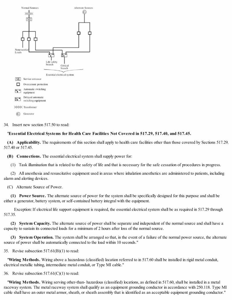
34. Insert new section 517.50 to read:
"Essential Electrical Systems for Health Care Facilities Not Covered in 517.29, 517.40, and 517.45.
(A) Applicability. The requirements of this section shall apply to health care facilities other than those covered by Sections 517.29,517.40 or 517.45.
(B) Connections. The essential electrical system shall supply power for:
(1) Task illumination that is related to the safety of life and that is necessary for the safe cessation of procedures in progress.
(2) All anesthesia and resuscitative equipment used in areas where inhalation anesthetics are administered to patients, includingalarm and alerting devices.
(C) Alternate Source of Power.
(1) Power Source. The alternate source of power for the system shall be specifically designed for this purpose and shall beeither a generator, battery system, or self-contained battery integral with the equipment.
Exception: If electrical life support equipment is required, the essential electrical system shall be as required in 517.29 through517.35.
(2) System Capacity. The alternate source of power shall be separate and independent of the normal source and shall have acapacity to sustain its connected loads for a minimum of 2 hours after loss of the normal source.
(3) System Operation. The system shall be arranged so that, in the event of a failure of the normal power source, the alternatesource of power shall be automatically connected to the load within 10 seconds."
35. Revise subsection 517.61(B)(1) to read:
"Wiring Methods. Wiring above a hazardous (classified) location referred to in 517.60 shall be installed in rigid metal conduit,electrical metallic tubing, intermediate metal conduit, or Type MI cable."
36. Revise subsection 517.61(C)(1) to read:
"Wiring Methods. Wiring serving other-than- hazardous (classified) locations, as defined in 517.60, shall be installed in a metalraceway system. The metal raceway system shall qualify as an equipment grounding conductor in accordance with 250.118. Type MIcable shall have an outer metal armor, sheath, or sheath assembly that is identified as an acceptable equipment grounding conductor."

37. Revise subsection 517.61(C)(4) to read:
"Anesthetizing Location Power Circuits. Each power circuit within, or partially within an anesthetizing location referred in517.60 shall be isolated from any distribution system by the use of an isolated power system."
(Added Coun. J. 9-6-17, p. 55278, Art. I, § 1)
14E-5-518 Assembly occupancies.
The provisions of Article 518 of NFPA 70 are adopted by reference with the following modifications:
1. Revise subsection 518.4(A) to read:
"General. The fixed wiring methods shall be metal raceways, flexible metal raceways, or Type MI cable.
Exception: Fixed wiring methods shall be as provided in Article 640 for audio signal processing, amplification, and reproductionequipment, in Article 800 for communications circuits, in Article 725 for Class 2 and Class 3 remote-control and signaling circuits, andin Article 760 for fire alarm circuits."
2. Delete subsections 518.4(B) and (C).
(Added Coun. J. 9-6-17, p. 55278, Art. I, § 1)
14E-5-520 Theaters, audience areas of motion picture and television studios, and similar locations.
The provisions of Article 520 of NFPA 70 are adopted by reference with the following modifications:
1. Revise subsection 520.5(A) to read:
"General. The fixed wiring methods shall be metal raceways or Type MI cable.
Exception: Fixed wiring methods shall be as provided in Article 640 for audio signal processing, amplification, and reproductionequipment, in Article 800 for communications circuits, in Article 725 for Class 2 and Class 3 remote-control and signaling circuits, andin Article 760 for fire alarm circuits."
2. Delete subsection 520.5(C).
(Added Coun. J. 9-6-17, p. 55278, Art. I, § 1)
14E-5-522 Control systems for permanent amusement attractions.
The provisions of Article 522 of NFPA 70 are adopted by reference without modification.
(Added Coun. J. 9-6-17, p. 55278, Art. I, § 1)
14E-5-525 Carnivals, circuses, fairs, and similar events.
The provisions of Article 525 of NFPA 70 are adopted by reference without modification.
(Added Coun. J. 9-6-17, p. 55278, Art. I, § 1)
14E-5-530 Motion picture and television studios and similar locations.
The provisions of Article 530 of NFPA 70 are adopted by reference with the following modification:
1. Revise section 530.11 to read:
"Permanent Wiring. The permanent wiring shall be Type MI cable, or in approved raceways.
Exception: Communications circuits; audio signal processing, amplification, and reproduction circuits; Class 1, Class 2, and Class 3remote-control or signaling circuits and power-limited fire alarm circuits shall be permitted to be wired in accordance with Articles 640,725, 760, and 800."
(Added Coun. J. 9-6-17, p. 55278, Art. I, § 1)
14E-5-540 Motion picture projection rooms.

The provisions of Article 540 of NFPA 70 are adopted by reference without modification.
(Added Coun. J. 9-6-17, p. 55278, Art. I, § 1)
14E-5-545 Manufactured buildings.
The provisions of Article 545 of NFPA 70 are not adopted. Article 545 shall read in its entirety:
"545.1 Scope. This article covers the requirements for a manufactured building and building components as herein defined.
545.2 Definitions.
Building Component. Any subsystem, subassembly, or other system designed for use in or
integral with or as part of a structure, which can include structural, electrical, mechanical, plumbing, and fire protection systems, andother systems affecting health and safety.
Closed Construction. Any building, building component, assembly, or system manufactured in such a manner that all concealedparts of processes of manufacture cannot be inspected after installation at the building site without disassembly, damage, ordestruction.
Manufactured Building. Any building that is of closed construction and is made or assembled in manufacturing facilities on or offthe building site for installation, or for assembly and installation on the building site, other than manufactured homes, mobile homes, parktrailers, or recreational vehicles.
545.3 Other Articles. Manufactured buildings shall comply with all applicable articles of this Code."
(Added Coun. J. 9-6-17, p. 55278, Art. I, § 1)
14E-5-547 Agricultural buildings.
The provisions of Article 547 of NFPA 70 are adopted by reference with the following modification:
1. Revise subsection 547.5(A) to read:
"Wiring Methods. Raceways suitable for the location, with approved termination fittings, shall be the wiring method employed. Thewiring methods of Article 502, Part II, shall be permitted for areas described in 547.1(A)."
(Added Coun. J. 9-6-17, p. 55278, Art. I, § 1)
14E-5-550 Mobile homes, manufactured homes, and mobile home parks.
The provisions of Article 550 of NFPA 70 are adopted by reference with the following modifications:
1. Revise section 550.1 to read:
"Scope. To the extent such installations are subject to regulation by the City of Chicago, the provisions of this article cover theelectrical conductors and equipment installed within or on mobile homes, the conductors that connect mobile to a supply of electricity,and the installation of electrical wiring, luminaires, equipment, and appurtenances related to electrical installations within a mobile homepark up to the mobile home service-entrance conductors or, if none, the mobile home service equipment.
Manufactured homes shall comply with Chapters 1 through 4 of this Code with regard to materials, electrical installation andelectrical construction methods.
Informational Note: For additional information on manufactured housing see NFPA 501-2013, Standard on Manufactured Housing,and Part 3280, Manufactured Home Construction and Safety Standards, of the Federal Department of Housing and UrbanDevelopment."
2. Revise section 550.10 to read:
"Power Supply.
(A) Feeder. The power supply to the mobile home shall be a feeder assembly consisting of a permanently installed feeder of atleast 60 amperes.
(B) Point of Entrance. The point of entrance of the feeder assembly to the mobile home shall be in the exterior wall, floor, or

roof.
(C) Mast Weatherhead or Raceway. The permanent feeder shall be installed by one of the following means:
(1) One mast weatherhead installation, installed in accordance with Article 230, containing four continuous, insulated, color-codedfeeder conductors, one of which shall be an equipment grounding conductor
(2) A metal raceway from the disconnecting means in the mobile home to the underside of the mobile home, with provisions forthe attachment to a suitable junction box or fitting to the raceway on the underside of the mobile home."
3. Revise Section 550.15 to read:
"Wiring Methods and Materials. Except as specifically limited in this section, the wiring methods and materials included in thisCode shall be used in mobile homes and manufactured homes.
(A) Metal Faceplates. Where metal faceplates are used, they shall be effectively grounded.
(B) Installation Requirements. If a range, clothes dryer, or similar appliance is connected by metal- covered cable or flexiblemetal conduit, a length of not less than 900 mm (3 ft) of free cable or conduit shall be provided to permit moving the appliance. Thecable or flexible metal conduit shall be secured to the wall. Type NM or Type SE cable shall not be used to connect a range or dryer.
(C) Raceways. Where rigid metal conduit or intermediate metal conduit is terminated at an enclosure with a locknut and bushingconnection, two locknuts shall be provided, one inside and one outside of the enclosure. Surface raceway shall be permitted. All cutends of conduit shall be reamed or otherwise finished to remove rough edges.
(D) Switches. Switches shall be rated as follows:
(1) For lighting circuits, switches shall be rated not less than 15 amperes, 120 to 125 volts, and in no case less than the connectedload.
(2) For motors or other loads, switches shall have ampere or horsepower ratings, or both, adequate for loads controlled. (An acgeneral-use snap switch shall be permitted to control a motor 2 hp or less with full-load current not over 80 percent of the switchampere rating.)
(E) Under-Chassis Wiring (Exposed to Weather).
(1) Where outdoor or under-chassis line- voltage (120 volts, nominal, or higher) wiring is exposed to moisture or physical damage,it shall be protected by rigid metal conduit or intermediate metal conduit. The conductors shall be suitable for wet locations.
Exception: Electrical metallic tubing or rigid nonmetallic conduit shall be permitted where closely routed against frames andequipment enclosures
(2) The conductors shall be Type TW, or equivalent.
(F) Boxes, Fittings, and Cabinets. Boxes, fittings, and cabinets shall be securely fastened in place and shall be supported from astructural member of the home, either directly or by using a substantial brace.
(G) Appliance Terminal Connections. Appliances having branch-circuit terminal connections that operate at temperatureshigher than 60°C (140°F) shall have circuit conductors as described in (1) or (2) of this subsection.
(1) Branch-circuit conductors having an insulation suitable for the temperature encountered shall be permitted to be run directlyto the appliance.
(2) Conductors having an insulation suitable for the temperature encountered shall be run from the appliance terminal connectionto a readily accessible outlet box placed at least 300 mm (1 ft) from the appliance. These conductors shall be in a suitable racewaythat shall extend for at least 1.2 m (4 ft).
(H) Component Interconnections. Fittings and connectors that are intended to be concealed at the time of assembly shall belisted and identified for the interconnection of building components. Such fittings and connectors shall be equal to the wiring methodemployed in insulation, temperature rise, and fault- current withstanding and shall be capable of enduring the vibration and shockoccurring in mobile home transportation."
(Added Coun. J. 9-6-17, p. 55278, Art. I, § 1)

14E-5-551 Recreational vehicles and recreational vehicle parks.
The provisions of Article 551 of NFPA 70 are adopted by reference without modification.
(Added Coun. J. 9-6-17, p. 55278, Art. I, § 1)
14E-5-552 Park trailers.
The provisions of Article 552 of NFPA 70 are adopted by reference with the following modification:
1. Revise section 552.48 to read:
"Wiring Methods.
(A) Wiring Systems. Cables and raceways shall be installed in accordance with the permissible Chapter 3 wiring methods, exceptas otherwise specified in this article. An equipment grounding means shall be provided in accordance with 250.118.
(B) Conduit and Tubing. Where rigid metal conduit or intermediate metal conduit is terminated at an enclosure with a locknutand bushing connection, two locknuts shall be provided, one inside and one outside of the enclosure. All cut ends of conduit and tubingshall be reamed or otherwise finished to remove rough edges.
(C) Boxes. In walls and ceilings constructed of wood or other combustible material, boxes and fittings shall be flush with thefinished surface or project therefrom.
(D) Mounting. Wall and ceiling boxes shall be mounted in accordance with Article 314.
Exception No. 1: Snap-in-type boxes or boxes provided with special wall or ceiling brackets that securely fasten boxes in walls orceilings shall be permitted.
Exception No. 2: A wooden plate providing a 1-1/2 in. minimum width backing around the box and of a thickness of 1/2 in. orgreater (actual) attached directly to the wall panel shall be considered as approved means for mounting outlet boxes.
(E) Raceway and Cable Continuity. Raceways and cable, shall be continuous between outlet boxes and other enclosures.
(F) Protected. Electrical metallic tubing shall be permitted to pass through the centers of the wide side of 2x4 wood studs.However, they shall be protected where they pass through 2x2 wood studs or at other wood studs or frames where the cable or tubingwould be less than 31.8 mm (1-1/4 in.) from the inside or outside surface. Steel plates on each side of the cable or tubing or a steeltube, with not less than 0.053 in. wall thickness, shall be installed to protect the cable or tubing.
(G) Cable Supports. Where connected with cable connectors or clamps, cables shall be secured and supported within 305 mm(12 in.) of outlet boxes, panelboards, and splice boxes on appliances. Supports and securing shall be provided at intervals not exceeding1.37 m (4.5 ft) at other places.
(H) Physical Damage. Where subject to physical damage, exposed nonmetallic cable shall be installed in metal raceways.
(I) Receptacle Faceplates. Metal faceplates shall comply with 406.5(A). Nonmetallic faceplates shall comply with 406.5(C).
(J) Metal Faceplates Grounded. Where metal faceplates are used, they shall be grounded.
(K) Moisture or Physical Damage. Where outdoor or under-chassis wiring is 120 volts, nominal, or over and is exposed tomoisture or physical damage, the wiring shall be protected by rigid metal conduit, by intermediate metal conduit, by electrical metallictubing, or by Type MI cable that is closely routed against frames and equipment enclosures or other raceway or cable identified for theapplication.
(L) Component Interconnections. Fittings and connectors that are intended to be concealed at the time of assembly shall belisted and identified for the interconnection of building components. Such fittings and connectors shall be equal to the wiring methodemployed in insulation, temperature rise, and fault-current withstanding, and shall be capable of enduring the vibration and shockoccurring in park trailers.
(M) Method of Connecting Expandable Units. The method of connecting expandable units to the main body of the park trailershall comply with the following as applicable:
(1) Cord-and-Plug Connected. Cord-and- plug connections shall comply with 552.48(M)(1)(a) through (M)(1)(d).

(a) The portion of a branch circuit that is installed in an expandable unit shall be permitted to be connected to the portion of thebranch circuit in the main body of the vehicle by means of a flexible cord or attachment plug and cord listed for hard usage. The cordand its connections shall comply with all provisions of Article 400 and shall be considered as a permitted use under 400.10.
(b) Where the receptacle provided for connection of the cord to the main circuit is located on the outside of the park trailer, itshall be protected with a ground-fault circuit interrupter for personnel and be listed for wet locations. A cord located on the outside ofa park trailer shall be identified for outdoor use.
(c) Unless removable or stored within the park trailer interior, the cord assembly shall have permanent provisions for protectionagainst corrosion and mechanical damage while the park trailer is in transit.
(d) The attachment plug and cord shall be installed so as not to permit exposed live attachment plug pins.
(2) Direct Wires Connected. That portion of a branch circuit that is installed in an expandable unit shall be permitted to beconnected to the portion of the branch circuit in the main body of the park trailer by means of flexible cord installed in accordance with552.48(M)(2)(a) through (M)(2)(f) or other approved wiring method.
(a) The flexible cord shall be listed for hard usage and for use in wet locations.
(b) The flexible cord shall be permitted to be exposed on the underside of the vehicle.
(c) The flexible cord shall be permitted to pass through the interior of a wall or floor assembly or both a maximum concealedlength of 610 mm (24 in.) before terminating at an outlet or junction box.
(d) Where concealed, the flexible cord shall be installed in nonflexible conduit or tubing that is continuous from the outlet orjunction box inside the park trailer to a weatherproof outlet box, junction box, or strain relief fitting listed for use in wet locations that islocated on the underside of the park trailer. The outer jacket of flexible cord shall be continuous into the outlet or junction box.
(e) Where the flexible cord passes through the floor to an exposed area inside of the park trailer, it shall be protected by meansof conduit and bushings or equivalent.
(f) Where subject to physical damage, the flexible cord shall be protected with RMC, IMC, Schedule 80 PVC, reinforcedthermosetting resin conduit (RTRC) listed for exposure to physical damage, or other approved means and shall extend at least 6 in.above the floor. A means shall be provided to secure the flexible cord where it enters the park trailer.
(N) Prewiring for Air-Conditioning Installation. Prewiring installed for the purpose of facilitating future air-conditioninginstallation shall comply with the applicable portions of this article and the following:
(1) An overcurrent protective device with a rating compatible with the circuit conductors shall be installed in the distributionpanelboard and wiring connections completed.
(2) The load end of the circuit shall terminate in a junction box with a blank cover or other listed enclosure. Where a junction boxwith a blank cover is used, the free ends of the conductors shall be adequately capped or taped.
(3) A safety label with the signal word WARNING in minimum 1/4 in. high letters and body text in minimum 1/8 in. high letterson a contrasting background. The safety label shall be affixed on or adjacent to the junction box and shall read:
AIR-CONDITIONING CIRCUIT. THIS CONNECTION IS FOR AIR CONDITIONERS RATED 110 - 125-VOLT AC, 60HZ, ___ AMPERES MAXIMUM. DO NOT EXCEED CIRCUIT RATING. EXCEEDING THE CIRCUIT RATING MAYCAUSE A FIRE AND RESULT IN DEATH OR SERIOUS INJURY.
An ampere rating, not to exceed 80 percent of the circuit rating, shall be legibly marked in the blank space.
(4) The circuit shall serve no other purpose.
(O) Prewiring for Other Circuits. Prewiring installed for the purpose of installing other appliances or devices shall comply withthe applicable portions of this article and the following:
(1) An overcurrent protection device with a rating compatible with the circuit conductors shall be installed in the panelboard withwiring connections completed.
(2) The load end of the circuit shall terminate in a junction box with a blank cover or a device listed for the purpose. Where ajunction box with blank cover is used, the free ends of the conductors shall be adequately capped or taped.

(3) A safety label with the signal word WARNING in minimum 1/4 in. high letters and body text in minimum 1/8 in. high letterson a contrasting background. The safety label shall be affixed to the junction box or device listed for the purpose and shall read:
THIS CONNECTION IS FOR ____ RATED ____ VOLT AC, 60 HZ, ____ AMPERES MAXIMUM. DO NOT EXCEEDTHE CIRCUIT RATING. EXCEEDING THE CIRCUIT RATING MAY CAUSE A FIRE AND RESULT IN DEATH ORSERIOUS INJURY.
The intended appliance type shall be legibly marked in the first blank space. An ampere rating not to exceed 80 percent of thecircuit rating shall be legibly marked in the second blank space."
(Added Coun. J. 9-6-17, p. 55278, Art. I, § 1)
14E-5-553 Floating buildings.
The provisions of Article 553 of NFPA 70 are adopted by reference with the following modification:
1. Revise subsection 553.7(B) to read:
"Wiring Methods. Liquidtight flexible metal conduit with approved fittings shall be permitted for feeders and where flexibleconnections are required for services. Extra-hard usage portable power cable listed for both wet locations and sunlight resistance shallbe permitted for a feeder to a floating building where flexibility is required. Other raceways suitable for the location shall be permittedto be installed where flexibility is not required."
(Added Coun. J. 9-6-17, p. 55278, Art. I, § 1)
14E-5-555 Marinas and boatyards.
The provisions of Article 555 of NFPA 70 are adopted by reference without modification.
(Added Coun. J. 9-6-17, p. 55278, Art. I, § 1)
14E-5-560 Residential occupancies.
The following language shall be inserted as a new Article 560:
"560 Residential Occupancies
Part I. General
560.1Scope. The special provisions of this section shall apply to the electrical installations in residential occupancies. In some casesthey are repetitious and in some cases they are variations of general requirements appearing elsewhere in this Code.
560.2 Wiring Methods.
(A) Low-Voltage Class 2 Wiring. Low-voltage wiring for control or signaling, telephone systems, antenna systems, orcommunication systems which is enclosed in building partitions, walls or in any way made inaccessible by building construction neednot be enclosed in a raceway except at locations where such wiring may be subject to mechanical injury.
Informational Note: Raceways when used will protect the conductors during construction and provide ready means forreplacement of conductors after the building is completed. These raceways need not terminate in a box or fitting as long as normalprecautions are taken to protect the conductors against injury.
(B) Other than Low-Voltage Class 2 Wiring. All wiring other than low-voltage class 2 wiring shall comply with the applicableprovisions of Chapter 3.
560.3 Smoke Detectors and Carbon Monoxide Detectors.
Smoke detectors and carbon monoxide detectors shall be provided and installed in accordance with Chapter 13-64 of the ChicagoBuilding Code.
Part II. Branch Circuits
560.4General. Part II specifies the branch circuit, receptacle outlets, and lighting outlet requirements. Voltages for branch-circuit,receptacle outlets and lighting outlets shall be limited to those specified in 210.6.

Informational Note: See 210.12 and exceptions for arc-fault circuit-interrupter (AFCI) protection requirements.
560.5Branch Circuit Requirements. Branch circuits for lighting and for appliances, including motor- operated appliances, shall beprovided to supply the loads computed in accordance with 220.10. These circuits shall comply with the requirements of 210.25. Inaddition, branch circuits shall be provided for specific loads not covered by 220.10 where required elsewhere in this Code and fordwelling unit loads as specified in 560.5(A) through (F).
(A) Number of Branch Circuits. The minimum number of branch circuits shall be determined from the total computed load andthe size or rating of the circuits used. In all installations, the number of circuits shall be sufficient to supply the load served. In no caseshall the load on any circuit exceed the maximum specified by 220.18.
(B) Small Appliance Branch Circuits. In addition to the number of branch circuits required by other parts of this section, two ormore 20-ampere small- appliance branch circuits shall be provided for all receptacle outlets specified by 560.6(B).
(C) Laundry Branch Circuits. In addition to the number of branch circuits required by other parts of this section, at least oneadditional 20-ampere branch circuit shall be provided to supply the laundry receptacle outlet(s) required by 560.6(F). This circuit shallhave no other outlets.
(D) Bathroom Branch Circuit. In addition to the number of branch circuits required by other parts of this section, at least one120-volt, 20-ampere branch circuit shall be provided to supply the bathroom(s) receptacle outlet(s). This circuit shall have no otheroutlets.
(E) Garage Branch Circuits. In addition to the number of branch circuits required by other parts of this section, at least one 120-volt, 20-ampere branch circuit shall be installed to supply receptacle outlets in garages. This circuit shall have no other outlets.
Exception: This circuit shall be permitted to supply readily accessible outdoor receptacle outlets
Informational Note: See 422.12 for central heating equipment branch circuit requirements.
(F) Guest Rooms. Branch circuits shall be installed in accordance with 210.60.
560.6Receptacle Outlet Requirements. This section provides requirements for 125-volt, 15- and 20-ampere receptacle outlets.The receptacles required by this section shall be in addition to any receptacle that is:
(1) Part of a luminaire or appliance, or
(2) Controlled by a wall switch in accordance with 210.70(A)(1), Exception No. 1, or
(3) Located within cabinets or cupboards, or
(4) Located more than 1.7 m (5-1/2 ft) above the floor
Permanently installed electric baseboard heaters equipped with factory-installed receptacle outlets or outlets provided as a separateassembly by the manufacturer shall be permitted as the required outlet or outlets for the wall space utilized by such permanentlyinstalled heaters. Such receptacle outlets shall not be connected to the heater circuits.
Informational Note No. 1: Listed baseboard heaters include instructions that may not permit their installation below receptacleoutlets.
Informational Note No. 2: See 210.8(A) for ground-fault circuit-interrupter (GFCI) protection requirements.
(A) General Provisions. In every kitchen, family room, dining room, living room, parlor, library, den, sunroom, bedroom,recreation room, or similar room or area of dwelling units, receptacle outlets shall be installed in accordance with the general provisionsspecified in 560.6(A)(1) through (A)(4).
(1) Spacing. Receptacles shall be installed such that no point measured horizontally along the floor line of any wall space is morethan 1.8 m (6 ft) from a receptacle outlet.
(2) Wall Space. As used in this section, a wall space shall include the following:
(1) Any space 600 mm (2 ft) or more in width (including space measured around corners) and unbroken along the floor line bydoorways and similar openings, fireplaces, and fixed cabinets that do not have countertops or similar work surfaces
(2) The space occupied by fixed panels in walls, excluding sliding panels

(3) The space afforded by fixed room dividers, such as freestanding bar-type counters or railings
(3) Floor Receptacles. Receptacle outlets in or on floors shall not be counted as part of the required number of receptacleoutlets unless located within 450 mm (18 in.) of the wall.
(4) Countertop and Similar Work Surface Receptacle Outlets. Receptacles installed for countertop and similar worksurfaces as specified in 560.6(C) shall not be considered as the receptacle outlets required by 560.6(A).
(B) Small Appliances.
(1) Receptacle Outlets Served. In the kitchen, pantry, breakfast room, dining room, or similar area of a dwelling unit, the twoor more 20-ampere small-appliance branch circuits required by 560.5(C)(1) shall serve all wall and floor receptacle outlets covered by560.6(A), all countertop outlets covered by 560.6(C), and receptacle outlets for refrigeration equipment.
Exception No. 1: In addition to the required receptacles specified by 560.6, switched receptacles supplied from a general-purpose branch circuit as defined in 560.7(A)(1), Exception No. 1, shall be permitted.
Exception No. 2: In addition to the required receptacles specified by 560.6, a receptacle outlet to serve a specific appliance shallbe permitted to be supplied from an individual branch circuit rated 15 amperes or greater.
(2) No Other Outlets. The two or more small-appliance branch circuits specified in 560.6(B)(1) shall have no other outlets.
Exception No. 1: A receptacle installed solely for the electrical supply to and support of an electric clock in any of the roomsspecified in 560.6(B)(1).
Exception No. 2: Receptacles installed to provide power for supplemental equipment and lighting on gas-fired ranges, ovens, orcounter-mounted cooking units.
(3) Kitchen Receptacle Requirements. Receptacles installed in a kitchen to serve countertop surfaces shall be supplied bynot fewer than two small- appliance branch circuits, either or both of which shall also be permitted to supply receptacle outlets in thesame kitchen and in other rooms specified in 560.6(B)(1). Additional small-appliance branch circuits shall be permitted to supplyreceptacle outlets in the kitchen and other rooms specified in 560.6(B)(1). No small-appliance branch circuit shall serve more than onekitchen.
(C) Countertops and Work Surfaces. In kitchens, pantries, breakfast rooms, dining rooms, and similar areas of dwelling units,receptacle outlets for countertop and work surfaces shall be installed in accordance with 560.6(C)(1) through (C)(5).
(1) Wall Countertop and Work Surface. A receptacle outlet shall be installed at each wall countertop and work surface that is300 mm (12 in.) or wider. Receptacle outlets shall be installed so that no point along the wall line is more than 600 mm (24 in.)measured horizontally from a receptacle outlet in that space.
Exception: Receptacle outlets shall not be required on a wall directly behind a range, counter- mounted cooking unit,or sink in the installation described in Figure 560.6(C)(1).
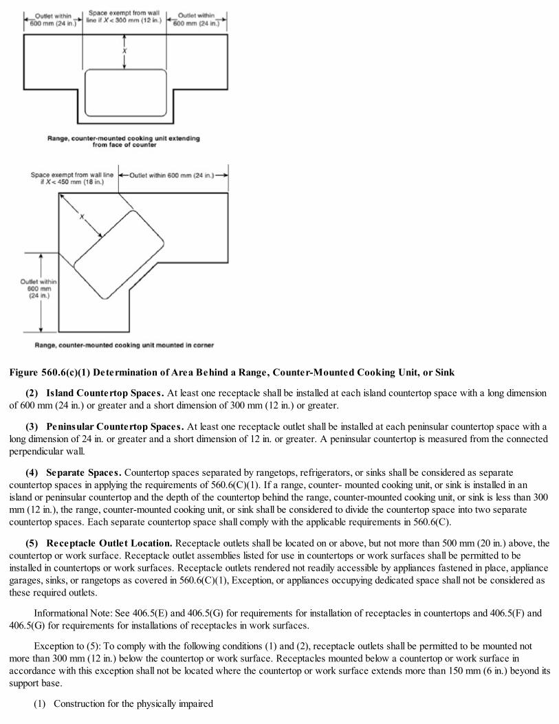
Figure 560.6(c)(1) Determination of Area Behind a Range, Counter-Mounted Cooking Unit, or Sink
(2) Island Countertop Spaces. At least one receptacle shall be installed at each island countertop space with a long dimensionof 600 mm (24 in.) or greater and a short dimension of 300 mm (12 in.) or greater.
(3) Peninsular Countertop Spaces. At least one receptacle outlet shall be installed at each peninsular countertop space with along dimension of 24 in. or greater and a short dimension of 12 in. or greater. A peninsular countertop is measured from the connectedperpendicular wall.
(4) Separate Spaces. Countertop spaces separated by rangetops, refrigerators, or sinks shall be considered as separatecountertop spaces in applying the requirements of 560.6(C)(1). If a range, counter- mounted cooking unit, or sink is installed in anisland or peninsular countertop and the depth of the countertop behind the range, counter-mounted cooking unit, or sink is less than 300mm (12 in.), the range, counter-mounted cooking unit, or sink shall be considered to divide the countertop space into two separatecountertop spaces. Each separate countertop space shall comply with the applicable requirements in 560.6(C).
(5) Receptacle Outlet Location. Receptacle outlets shall be located on or above, but not more than 500 mm (20 in.) above, thecountertop or work surface. Receptacle outlet assemblies listed for use in countertops or work surfaces shall be permitted to beinstalled in countertops or work surfaces. Receptacle outlets rendered not readily accessible by appliances fastened in place, appliancegarages, sinks, or rangetops as covered in 560.6(C)(1), Exception, or appliances occupying dedicated space shall not be considered asthese required outlets.
Informational Note: See 406.5(E) and 406.5(G) for requirements for installation of receptacles in countertops and 406.5(F) and406.5(G) for requirements for installations of receptacles in work surfaces.
Exception to (5): To comply with the following conditions (1) and (2), receptacle outlets shall be permitted to be mounted notmore than 300 mm (12 in.) below the countertop or work surface. Receptacles mounted below a countertop or work surface inaccordance with this exception shall not be located where the countertop or work surface extends more than 150 mm (6 in.) beyond itssupport base.
(1) Construction for the physically impaired

(2) On island and peninsular countertops where the countertop is flat across its entire surface (no backsplashes, dividers, etc.)and there are no means to mount a receptacle within 500 mm (20 in.) above the countertop, such as an overhead cabinet
(D) Bathrooms. At least one receptacle outlet shall be installed in bathrooms within 900 mm (3 ft) of the outside edge of eachbasin. The receptacle outlet shall be located on a wall or partition that is adjacent to the basin or basin countertop, located on thecountertop, or installed on the side or face of the basin cabinet. In no case shall the receptacle be located more than 300 mm (12 in.)below the top of the basin or basin countertop. Receptacle outlet assemblies listed for use in countertops shall be permitted to beinstalled in the countertop
Informational Note: See 406.5(E) and 406.5(G) for requirements for installation of receptacles in countertops.
(E) Outdoor Outlets. Outdoor receptacle outlets shall be installed in accordance with 560.6(E)(1) through (E)(3).
Informational Note: See 210.8(A)(3).
(1) One-Family and Two-Family Dwellings. For a one-family dwelling and each unit of a two-family dwelling that is at gradelevel, at least one receptacle outlet readily accessible from grade and not more than 2.0 m (6-1/2 ft) above grade level shall be installedat the front and back of the dwelling.
(2) Multifamily Dwellings. For each dwelling unit of a multifamily dwelling where the dwelling unit is located at grade level andprovided with individual exterior entrance/egress, at least one receptacle outlet readily accessible from grade and not more than 2.0 m(6-1/2 ft) above grade level shall be installed.
(3) Balconies, Decks, and Porches. Balconies, decks, and porches that are attached to the dwelling unit and are accessiblefrom inside the dwelling unit shall have at least one receptacle outlet accessible from the balcony, deck, or porch. The receptacle shallnot be located more than 2.0 m (6-1/2 ft) above the balcony, deck, or porch walking surface.
(F) Laundry Areas. In dwelling units, at least one receptacle outlet shall be installed in areas designated for the installation oflaundry equipment.
Exception No. 1: A receptacle for laundry equipment shall not be required in a dwelling unit of a multifamily building where laundryfacilities are provided on the premises for use all by all building occupants.
Exception No. 2: A receptacle for laundry equipment shall not be required in other than one-family dwellings where laundryfacilities are not to be installed or permitted.
(G) Basements, Garages, and Accessory Buildings. For one- and two- family dwellings, at least one receptacle outlet shall beinstalled in the areas specified in 560.6(G)(1) through (3). These receptacles shall be in addition to receptacles required for specificequipment.
(1) Garages. In each garage at least one receptacle outlet shall be installed in each vehicle bay and not more than 1.7 m (5-1/2ft) above the floor.
(2) Accessory Buildings. In each accessory building with electric power.
(3) Basements. In each separate unfinished portion of a basement
(H) Hallways. In dwelling units, hallways of 3.0 m (10 ft) or more in length shall have at least one receptacle outlet.
As used in this subsection, the hallway length shall be considered the length along the centerline of the hallway without passingthrough a doorway.
(I) Foyers. Foyers that are not part of a hallway in accordance with 560.6(H) and that have an area that is greater than 5.6 m2
(60 ft2) shall have a receptacle(s) located in each wall space 900 mm (3 ft) or more in width. Doorways, door side windows thatextend to the floor, and similar openings shall not be considered wall space.
560.7Lighting Outlets Required. Lighting outlets shall be installed where specified in 560.7(A), (B), and (C).
(A) Dwelling Units. In dwelling units, lighting outlets shall be installed in accordance with 560.7(A)(1), (A)(2), and (A)(3).
(1) Habitable Rooms. At least one wall switch-controlled lighting outlet shall be installed in every habitable room, kitchen, andbathroom.

Exception No. 1: In other than kitchens and bathrooms, one or more receptacles controlled by a wall switch shall be permitted inlieu of lighting outlets.
Exception No. 2: Lighting outlets shall be permitted to be controlled by occupancy sensors that are (1) in addition to wallswitches or (2) located at a customary wall switch location and equipped with a manual override that will allow the sensor to functionas a wall switch.
(2) Additional Locations. Additional lighting outlets shall be installed in accordance with the following:
(1) At least one wall switch-controlled lighting outlet shall be installed in hallways, stairways, and garages.
(2) For dwelling units, garages, at least one wall switch-controlled lighting outlet shall be installed to provide illumination on theexterior side of outdoor entrances or exits with grade level access. A vehicle door in a garage shall not be considered as an outdoorentrance or exit.
(3) Where one or more lighting outlet(s) are installed for interior stairways, there shall be a wall switch at each floor level, andlanding level that includes an entryway, to control the lighting outlet(s) where the stairway between floor levels has six risers or more.
Exception to (A)(2)(1), (A)(2)(2), and (A)(2)(3): In hallways, in stairways, and at outdoor entrances, remote, central, orautomatic control of lighting shall be permitted.
(4) Lighting outlets controlled in accordance with 560.7(A)(2)(3) shall not be controlled by the use of dimmer switches unlessthey provide the full range of dimming control at each location.
(5) At least one wall switch-controlled lighting outlet shall be installed in clothes closets over 2.3m2 (25 ft²). Closet luminairesshall be permanently installed lighting outlets.
(6) At least one wall switch-controlled lighting outlet shall be installed over each sink or basin in a room or area that is greaterthan 5.95 m2 (64 ft2). Such lighting outlets shall be in addition to the general lighting outlets installed in the room or area.
(3) Storage or Equipment Spaces. For attics, underfloor spaces, utility rooms, and basements, at least one lighting outletcontaining a switch or controlled by a wall switch shall be installed where these spaces are used for storage or contain equipmentrequiring servicing. At least one point of control shall be at the usual point of entry to these spaces. The lighting outlet shall be providedat or near the equipment requiring servicing.
(B) Emergency Systems. For multifamily dwelling units containing five or more units, in addition to the lighting outlets required in560.7(A)(2), lighting outlets shall be installed in accordance with Article 700. The lighting outlets required to illuminate corridors andstairwells may be connected to a photocell located in the area to be illuminated if adequate natural illumination is present duringdaylight hours to illuminate those areas. Time clocks shall not be used. These emergency lights shall supplement normal lighting instairwells and corridors.
High rise buildings containing dwelling units shall comply with 700.30 and 700.65.
Exception: On existing buildings not exceeding four stories in height containing only vertical stairwells (no corridors) all of thestairwell lights may be connected to the emergency service. Normal lighting will not be required in these stairwells.
Part III. Branch-Circuit, Feeder, and Service Calculations
560.8Scope. 560.9 to 560.21 provide the requirements for computing branch-circuit, feeder, and service loads.
560.9 Calculations.
(A) Voltages. Unless other voltages are specified, for purposes of computing branch-circuit and feeder loads, nominal systemvoltages of 120,
120/240, 208Y/120, and 240 volts shall be used.
(B) Fractions of an Ampere. Except where computations result in a fraction of an ampere 0.5 or larger, such fractions shall bepermitted to be dropped.
560.10Computation of Branch Circuit Loads. Branch-circuit loads shall be computed as shown in (A) and (B) of this section.
(A) Lighting Load. A unit load of not less than 3VA shall constitute the minimum lighting load for each square foot of floor area.
The floor area for each floor shall be computed from the outside dimensions of the building, dwelling unit, or other area involved. Thecomputed floor area shall not include open porches, garages, or unused or unfinished spaces not adaptable for future use.
(B) Other Loads. The minimum load for each outlet for general-use receptacles and outlets not used for general illumination shallnot be less than that computed in (1) through (5) of this subsection, the loads shown being based on nominal branch-circuit voltages.
(1) Specific Appliances or Loads. An outlet for a specific appliance or other load not covered in (2) through (5) of thissubsection shall be computed based on the ampere rating of the appliance or load served.
(2) Electric Dryers and Household Electric Cooking Appliances. Load computations shall be permitted as specified in560.18 for electric dryers and 560.19 for electric ranges and other cooking appliances.
(3) Motor Loads. Outlets for motor loads shall be computed in accordance with the requirements in 430.22 and 430.24 andArticle 440.
(4) Recessed Lighting Fixtures. An outlet supplying recessed lighting fixture(s) shall be computed based on the maximumvolt-ampere rating of the equipment and lamps for which the fixture(s) is rated.
(5) Dwelling Occupancies. In one-family, two-family, and multifamily dwellings and in guest rooms of hotels and motels, theoutlets specified in (a), (b), and (c) of this subsection are included in the general lighting load calculations of 560.9. No additional loadcalculations shall be required for such outlets.
a. All general-use receptacle outlets of 20-ampere rating or less, including receptacles connected to the circuits in 560.5(C)(3).
b. The receptacle outlets specified in 560.6(E) and (G).
c. The lighting outlets specified in 560.7(A) and (B).
560.11Maximum Loads. The total load shall not exceed the rating of the branch circuit and it shall not exceed the maximum loadsspecified in (A) through (C) of this section, under the conditions specified therein.
(A) Motor-Operated and Combination Loads. Where a circuit supplies only motor-operated loads, Article 430 shall apply.Where a circuit supplies only air-conditioning equipment, refrigerating equipment, or both, Article 440 shall apply. For circuits supplyingloads consisting of motor-operated utilization equipment that is fastened in place and that has a motor larger than 1/8 hp in combinationwith other loads, the total computed load shall be based on 125 percent of the largest motor load plus the sum of the other loads.
(B) Inductive and LED Lighting Loads. For circuits supplying lighting units that have ballasts, transformers, autotransformers,or LED drivers, the computed load shall be based on the total ampere ratings of such units and not on the total watts of the lamps.
(C) Range Loads. It shall be permissible to apply demand factors for range loads in accordance with Table 220.55, including Note4.
560.12 Computed Load of Feeders and Services. The computed load of a feeder or service shall not be less than the sum ofthe loads on the branch circuits supplied, as determined by 560.7 through 560.10 after any applicable demand factors permitted by560.12 through 560.20 have been applied.
560.13General Lighting. The demand factors specified in Table 560.12 shall apply to that portion of the total branch-circuit loadcomputed for general illumination. They shall not be applied in determining the number of branch circuits for general illumination.
Table 560.13.Lighting Load Demand Factors
Type of Occupancy
Portion of LightingLoad to WhichDemand FactorApplies (Volt-
Amperes)
Demand Factor (%)
First 3000 atFrom 3001 to 120,000 100

Dwelling units atRemainder over120,000 at
3525
Hotels and motelsincluding apartmenthouses withoutprovision for cookingby tenants*
First 20,000 or less atNext 80,000 atRemainder over100,000 at
504030
*The demand factors of this table shall not apply in the computed loadof feeders or services supplying areas in hotels, and motels where theentire lighting is likely to be used at one time, as in ballrooms ordining rooms.
560.14Motors. Motor loads shall be computed in accordance with 430.22, 430.24, 430.25, and 430.26 and with 440.6 for hermeticrefrigerant motor-compressors.
560.15Fixed Electric Space Heating. Fixed electric space heating loads shall be computed at 100 percent of the total connectedload; however, in no case shall a feeder or service load current rating be less than the rating of the largest branch circuit supplied.
Exception: Where reduced loading of the conductors results from units operating on duty-cycle, intermittently, or from all units notoperating at one time, the authority having jurisdiction may grant permission for feeder conductors to have an ampacity less than 100percent, provided the conductors have an ampacity for the load so determined.
560.16 Small Appliance and Laundry Loads.
(A) Small Appliance Circuit Load. In each dwelling unit, the load shall be computed at 1500 volt- amperes for each 2-wiresmall-appliance branch circuit required by 560.5(C)(1). Where the load is subdivided through two or more feeders, the computed loadfor each shall include not less than 1500 volt-amperes for each 2-wire small-appliance branch circuit. These loads shall be permitted tobe included with general lighting load and subjected to the demand factors provided in Table 560.13.
Exception: The individual branch circuit permitted by 560.6(B)(1), Exception No. 2 shall be permitted to be excluded from thecalculation required by 560.16.
(B) Laundry Circuit Load. A load of not less than 1500 volt-amperes shall be included for each 2-wire laundry branch circuitinstalled as required by 560.5(C)(2). This load shall be permitted to be included with the general lighting load and subjected to thedemand factors provided in Table 560.13.
560.17Appliance Load. It shall be permissible to apply a demand factor of 75 percent to the nameplate rating load of four or moreappliances fastened in place, other than electric ranges, clothes dryers, space-heating equipment, or air-conditioning equipment, that areserved by the same feeder or service in a one-family, two-family, or multifamily dwelling.
560.18Electric Clothes Dryers. The load for household electric clothes dryers in a dwelling unit(s) shall be 5000 watts (volt-amperes) or the nameplate rating, whichever is larger, for each dryer served. The use of the demand factors in Table 220.54 shall bepermitted. Where two or more single-phase dryers are supplied by a 3-phase, 4-wire feeder or service, the total load shall be computedon the basis of twice the maximum number connected between any two phases. Kilovolt-amperes (kVA) shall be consideredequivalent to kilowatts (kW) for loads computed in this section.
560.19Electric Ranges and Other Cooking Appliances. The demand load for household electric ranges, wall-mounted ovens,counter-mounted cooking units, and other household cooking appliances individually rated in excess of 1-3/4 kW shall be permitted tobe computed in accordance with Table 220.55. Kilovolt-amperes (kVA) shall be considered equivalent to kilowatts (kW) for loadscomputed in this section.
Where two or more single-phase ranges are supplied by a 3-phase, 4-wire feeder or service, the total load shall be computed on thebasis of twice the maximum number connected between any two phases.
560.20Noncoincident Loads. Where it is unlikely that two dissimilar loads will be in use simultaneously, it shall be permissible toomit the smaller of the two loads(s) in computing the total load of a feeder or service.

560.21 Feeder or Service Neutral Load.
(A) Basic Calculation. The feeder or service neutral load shall be the maximum unbalance of the load determined by this article.The maximum unbalanced load shall be the maximum net calculated load between the neutral conductor and any one ungroundedconductor.
Exception: For 3-wire, 2-phase or 5-wire, 2-phase systems, the maximum unbalanced load shall be the maximum net calculatedload between the neutral conductor and any one ungrounded conductor multiplied by 140 percent.
(B) Permitted Reductions. A service or feeder supplying the following loads shall be permitted to have an additional demandfactor of 70 percent applied to the amount in 560.21(B)(1) or portion of the amount in 560.21(B)(2) determined by the following basiccalculations:
(1) A feeder or service supplying household electric ranges, wall-mounted ovens, counter-mounted cooking units, and electricdryers, where the maximum unbalanced load has been determined in accordance with Table 220.55 for ranges and Table 220.54 fordryers
(2) That portion of the unbalanced load in excess of 200 amperes where the feeder or service is supplied from a 3-wire dc orsingle-phase ac system; or a 4-wire, 3-phase system; or a 3-wire, 2-phase system; or a 5-wire, 2-phase system
(C) Prohibited Reductions. There shall be no reduction of the neutral or grounded conductor capacity applied to the amount in560.21(C)(1), or portion of the amount in (C)(2), from that determined by the basic calculation:
(1) Any portion of a 3-wire circuit consisting of 2 ungrounded conductors and the neutral conductor of a 4-wire, 3-phase, wye-connected system
(2) That portion consisting of nonlinear loads supplied from a 4-wire, wye-connected, 3-phase system
Informational Note: A 3-phase, 4-wire, wye- connected power system used to supply power to nonlinear loads may necessitatethat the power system design allow for the possibility of high harmonic neutral-conductor currents
Part IV. Services and Service Disconnecting Means
560.22 Services and Service-Entrance Conductors.
(A) General. Services shall comply with the requirements of Article 230.
(B) Size and Rating of Service Conductors.
(1) General. The ampacity of the service- entrance conductors before the application of any adjustment or correction factors,shall not be less than either (a) or (b) of this subsection. Loads shall be calculated in accordance with Article 220. Allowable ampacityshall be determined from Article 310.
(2) Continuous and Noncontinuous Loads. Continuous and noncontinuous loads shall be calculated in accordance with either(a) or (b) below.
(a) The sum of the noncontinuous loads plus 125% of continuous loads.
(b) The sum of the noncontinuous load plus the continuous load if the service entrance conductors terminate in an overcurrentdevice that is listed for operations at 100% of its rating.
(3) Ungrounded Conductors. Ungrounded conductors shall have an ampacity of not less than the minimum rating of thedisconnecting means specified in 230.79.
(4) Grounded Conductors. The grounded conductor shall not be less than the minimum size as required by 250.24(B).Grounded conductors shall be the same size as the ungrounded conductors for all services up to and including 400 amperes.
560.23 Service Disconnecting Means.
(A) General. Means shall be provided to disconnect all conductors from the service-entrance conductors.
(B) Location. The service disconnecting means shall be installed in accordance with 560.23(B)(1), (B)(2), and (B)(3),(A)(4), and(A)(5).

(1) One- and Two-Family Dwellings. In one- and two-family dwellings the service disconnecting means shall be installed at areadily accessible location in the basement or first floor of the building at a point not exceeding 1.52 m (5 ft) from the point of entryinto the building. When the length of the service raceway exceeds 1.52 m (5 ft) from the point of entry into the building, the serviceraceway shall conform to the requirements of 230.6.
(2) In Other Than One- and Two-Family Dwellings. In other than one- and two- family dwellings, the service disconnectingmeans shall be installed at a readily accessible location either outside of the building or structure or inside the building or structurenearest the point of entrance of the service conductors. When the length of the service raceway exceeds 1.52 m (5 ft) from the pointof entry into the building, the service raceway shall conform to the requirements of 230.6.
(3) Bathrooms. Service disconnecting means shall not be installed in bathrooms.
(4) Remote Control. Where a remote control device(s) is used to actuate the service disconnecting means, the servicedisconnecting means shall be located in accordance with 230.70(A)(1).
(5) High Rise Buildings. In high rise buildings and other similar buildings of large area, the disconnecting means for the multipleservices recognized by 230.2(B)(2) shall be located in a dedicated fire-rated room as near as practical to the serving utility vault.
The rooms for the "main" service disconnecting means which serve the building common element loads shall have a 3-hour firerating. The electrical service rooms for tenant loads shall have a 2-hour minimum fire rating. These rooms shall be for the exclusiveuse of electrical equipment.
Where more than one service is permitted to serve one floor, the various disconnecting means and their locations shall beprominently identified as required by 230.2(E).
(6) Multiple Occupancy Buildings. Each occupant shall have access to the occupant's service disconnecting means. In amultiple occupancy building supplied by a single service with a
common accessible space available, the disconnecting means may consist of no more than six switches which shall be inaccordance with the requirements of 230.71.
(C) Marking. Each service disconnect shall be permanently marked to identify it as a service disconnect.
(D) Rating of Service Disconnecting Means. The service disconnecting means shall have a rating not less than the load to becarried, determined in accordance with Article 220. In no case shall the rating be lower than specified in (1), (2), (3), or (4) of thissubsection.
(1) One-Circuit Installation. For installations to supply only limited loads of a single branch circuit, the service disconnectingmeans shall have a rating of not less than 15 amperes.
(2) Two-Circuit Installations. For installations consisting of not more than two 2-wire branch circuits, the service disconnectingmeans shall have a rating of not less than 30 amperes.
(3) One-Family Dwelling. For a one-family dwelling, the service disconnecting means shall have a rating of not less than 100amperes, 3-wire.
(4) All Others. For all other installations, the service disconnecting means shall have a rating of not less than 60 amperes.
560.24 Metering. Where a current supply is separately metered as in an apartment building, each such separately metered loadshall be equipped with a meter disconnecting means which will disconnect the separately meter load from its source of supply. Suchdisconnect(s) shall conform to provisions of Part VI of Article 230.
Meters and disconnects shall be grouped and shall be located in meter closets if they are not installed in the basement. In all cases,the meter disconnect shall be immediately adjacent to its own meter. However where six or fewer meters are installed outside thebuilding the foregoing provisions shall not apply, and in such cases the meter disconnects shall be installed in accordance with 560.23."
(Added Coun. J. 9-6-17, p. 55278, Art. I, § 1; Amend Coun. J. 11-8-17, p. 59720, § 22)
14E-5-570 Requirements for existing dwelling-type occupancies not exceeding four stories in height.
The following language shall be inserted as a new Article 570:
"570 Requirements for Existing Dwelling Units in Buildings Not Exceeding Four Stories in Height

570.1Scope. This article covers the electrical requirements, installation requirements, and connection requirements for an existingdwelling unit in a building not exceeding four stories in height, including an existing dwelling unit in a building of mixed occupancy notexceeding four stories in height, and the common areas serving those dwelling units, when the alterations, remodeling, or repairs do notencompass 60% or more of the building structure, dwelling unit, or electrical system.
570.2Not Covered. Dwelling occupancies not covered in 570.1 shall comply with Article 560 and other applicable articles of thisCode.
570.3General. All electrical installations, alterations and repairs shall be performed by an electrical contractor.
570.4Permits. The electrical contractor shall obtain an electrical permit for all electrical work to be performed. Electrical permitsshall be obtained before any work is started.
570.5Plans. All plans and load calculations required by 215.5 shall be submitted before any electrical work is started. All plans andload calculations are subject to field inspection.
570.6Electrical Heating. All electrical heat installations and conversions shall conform to the provisions of Articles 422 and 424.
570.7Emergency Lighting. All buildings which contain five or more dwelling units shall conform
to the provisions of Article 700, as they apply to emergency lighting requirements.
570.8Ground Fault Circuit-Interrupter Protection for Personnel. All 125-volt, single phase, 15- and 20-ampere receptacleoutlets installed in bathrooms, garages, counter top spaces, unfinished basements and outdoor locations shall have ground fault circuitinterrupter protection for personnel.
Informational Note: See 210.12 and exceptions for arc-fault circuit-interrupter (AFCI) protection requirements.
570.9Minimum Standards. When alterations, remodeling, or repairs encompass less than 60% of a building structure, dwelling unit,or electrical system, the wiring serving such building or structure shall conform to (a), (b), and (c) of this section.
(a) Any part of the building structure, dwelling unit, or electrical system upon which alterations, remodeling, or repairs areperformed shall comply with the provisions of 570.10(A) through (I) and the other applicable sections of this Code.
(b) For existing dwelling occupancies not exceeding four stories in height or in the residential portion of an existing building of mixedoccupancy not exceeding four stories in height, the portion of the building being altered, remodeled, or repaired shall comply with theprovisions of 570.10(A) through (I).
In addition, there shall be a minimum of 60 amperes supply for each altered, remodeled, or repaired dwelling unit that is not a hotelor motel guest room.
Informational Note: Mixed occupancies include but are not limited to, mixed commercial and dwelling types.
(c) Simple repairs that do not involve structural alterations, such as replacing non-functioning switches, shall comply with theprovisions of 570.10 (A), (B), (G), (H) and (I).
570.10. Specific Requirements.
(A) Ampacity Requirements. All existing electrical service, feeders, branch circuits, or system and equipment grounding,required to meet the standards set forth in this section shall be in an approved, acceptable condition and shall be of adequate ampacityfor the load being served. For the purposes of this requirement, any existing electrical service being altered, remodeled or repaired shallbe a minimum of 60 amperes supply for each dwelling unit that is not a hotel or motel guest room.
(B) Overcurrent Protection. All over-current protection required to meet the standards set forth in this section shall be of theproper size. When plug fuses are utilized, they shall be "Type S."
(C) Branch Lighting Circuits. Each dwelling unit shall be provided with a minimum of one 15-ampere general lighting branchcircuit for each 46.5 m2 (500 ft2) of living space. This branch circuit may supply the general use receptacle outlets.
(D) Small Appliance Branch Circuits. Each dwelling unit shall be provided with a minimum of one 20-ampere small appliancebranch circuit to supply a minimum of two receptacle outlets serving countertops in each kitchen. This circuit shall be permitted to alsoserve a laundry receptacle.

(E) Receptacle Outlet Requirements. An adequate number of receptacle outlets shall be provided in every habitable room ofeach dwelling unit to eliminate the need for the use of cord extension wiring. The minimum number of receptacle outlets required forvarious sized rooms is shown in Table 570.10.
Receptacle outlets serving kitchen countertops shall be ground-fault circuit-interrupter protected. At least one ground-fault circuit-interrupter protected wall mounted receptacle outlet shall be installed in each bathroom adjacent to the basin.
(F) Lighting Outlets Required. At least one wall switch-controlled lighting outlet shall be installed in each habitable room.Closets shall be adequately illuminated and shall contain light fixtures with a completely enclosed lamp, unless adequate illumination issupplied from adjacent fixtures outside the closet.
(G) Covers. All electrical boxes and outlets shall be provided with approved covers or plates.
(H) Smoke Alarms. Smoke alarms as required by the Chicago Building Code shall be installed. All smoke alarms shall beapproved.
(I) Carbon Monoxide Detectors. Carbon monoxide detectors as required by the Chicago Building Code shall be installed. Allcarbon monoxide detectors shall be approved.
Table 570.10 Minimum Receptacle Outlets Required
Room SizeMinimum Receptacle
Outlets Required*
1 to 64 ft2(example 8 ft x 8 ft)
2, on opposite walls
65 to 100 ft2(example 10 ft x 10 ft)
3, on adjacent walls
greater than 100 ft2(example 12 ft x 12 ft)
1 on each wall
* Where a straight wall exceeds 20 ft, a minimum ofone receptacle outlet shall be provided for every 18ft of that wall.
570.11Wiring Methods. In addition to those wiring methods recognized in Chapter 3, the following wiring method is recognized assuitable:
Trade size 3/8 flexible metal conduit or listed MC cable may be used for extensions to general lighting or appliance branch circuitsnot exceeding 20 amperes. Trade size 3/8 flexible metal conduit and MC cable extensions are permitted between an existing outlet andtwo new outlets located in new or existing walls or partitions. Installation of trade size 3/8 flexible metal conduit and MC cableextensions shall be permitted in lengths up to 7.62 m (25 ft). The number of conductors permitted in a trade size 3/8 flexible metalconduit extension shall conform to Table 570.11. All flexible metal conduit shall contain a properly sized equipment groundingconductor sized to Table 250.122.
Table 570.11 Maximum Number of Insulated Conductors in Trade Size 3/8 Flexible Metal Conduit*
Size(AWG)
FittingLocation
Type
RFH-2,SF-2
TF,XHHW,
TFN,THHN,
FEP,FEBP,
PF,
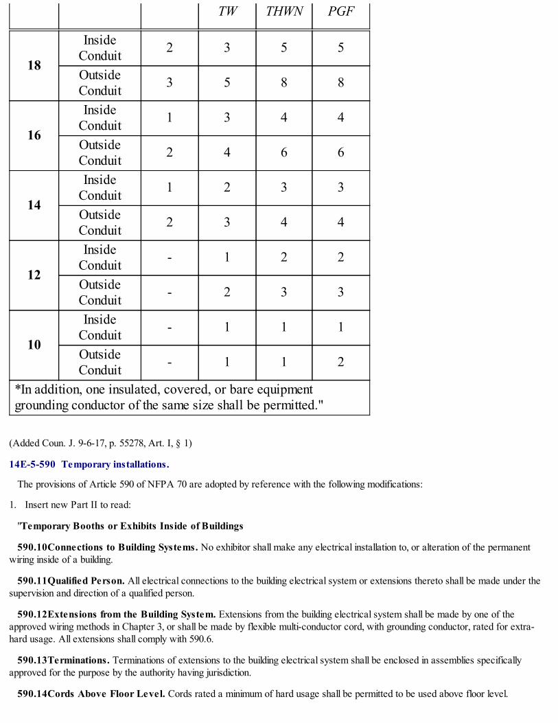
TW THWN PGF
18
InsideConduit 2 3 5 5
OutsideConduit 3 5 8 8
16
InsideConduit 1 3 4 4
OutsideConduit 2 4 6 6
14
InsideConduit 1 2 3 3
OutsideConduit 2 3 4 4
12
InsideConduit - 1 2 2
OutsideConduit - 2 3 3
10
InsideConduit - 1 1 1
OutsideConduit - 1 1 2
*In addition, one insulated, covered, or bare equipmentgrounding conductor of the same size shall be permitted."
(Added Coun. J. 9-6-17, p. 55278, Art. I, § 1)
14E-5-590 Temporary installations.
The provisions of Article 590 of NFPA 70 are adopted by reference with the following modifications:
1. Insert new Part II to read:
"Temporary Booths or Exhibits Inside of Buildings
590.10Connections to Building Systems. No exhibitor shall make any electrical installation to, or alteration of the permanentwiring inside of a building.
590.11Qualified Person. All electrical connections to the building electrical system or extensions thereto shall be made under thesupervision and direction of a qualified person.
590.12Extensions from the Building System. Extensions from the building electrical system shall be made by one of theapproved wiring methods in Chapter 3, or shall be made by flexible multi-conductor cord, with grounding conductor, rated for extra-hard usage. All extensions shall comply with 590.6.
590.13Terminations. Terminations of extensions to the building electrical system shall be enclosed in assemblies specificallyapproved for the purpose by the authority having jurisdiction.
590.14Cords Above Floor Level. Cords rated a minimum of hard usage shall be permitted to be used above floor level.

590.15Arrangement of Cords. All cords shall be arranged in lengths and patterns, in a workmanlike manner, to avoid excess cordhazards.
590.16Grounding. All flexible multiconductor cords shall have a grounding conductor and be rated for extra-hard usage or hardusage as permitted in 590.12 and 590.14, unless the cord is a component of an approved assembly.
590.17Traffic Area. No cord shall be run across any space where subject to traffic unless the cord is enclosed in a substantialenclosure specifically approved for the purpose.
590.18Cord Overcurrent Protection. All cords shall be protected by a properly sized overcurrent device.
590.19Approval. For the purposes of this Article, all electrical equipment or appliances connected to the building electrical systemor extensions thereto in booths or displays shall be:
(1) Listed and labeled in accordance with 110.3; or
(2) Specifically approved by the authority having jurisdiction and subject to field inspection.
Informational Note: An unlisted foreign luminaire is an example of material which would require specific approval under (2) of thissection.
590.20Permanent Wiring. Wiring permanently installed on all booths or displays including prewired booths brought in forconnection to the building electrical system shall be enclosed in a raceway as allowed by a wiring method recognized in Chapter 3.Where flexibility is necessary, such as between booth sections and at connection points to the building electrical system or supplypoints, properly rated cord in lengths not to exceed 1.83 m (6 ft) and equipped with approved attachment plugs shall be permitted to beutilized.
590.21Splices. All splices and terminations shall be made in approved metal enclosures.
590.22Supports. No electrical equipment shall be attached to or supported by either dividers or curtains.
590.23Fastened in Place. All electrical equipment shall be securely fastened in place using a recognized method.
Informational Note: Velcro, glue, tape, or similar methods are not suitable as a means of attachment.
590.24Live Parts. There shall be no exposed energized current-carrying metal parts.
590.25Exposed Metal Parts. All exposed noncurrent-carrying parts of the installations shall be effectively grounded inaccordance with Article 250 of this Code.
590.26Combustible Material. No electrical equipment or appliance which, under normal operating conditions, attains a surfacetemperature in excess of 90°C (194°F) shall be mounted on or supported from any combustible material, unless separated therefromby a substantial noncombustible material.
590.27Lighting Fixtures. Lighting fixtures or other appliances or equipment having other than a cord as outlined in 590.12 through590.15 shall be permitted to be accepted provided the complete assembly, including the cord, is listed and labeled in accordance with110.3.
590.28Custom Displays. Unlabeled custom-made light fixtures and displays shall be permitted when fabricated using all listed andlabeled components. Fabrication shall be by an electrical contractor. All equipment of this type shall be specifically approved by theauthority having jurisdiction and shall be subject to field inspection.
590.29Overcurrent Protection. All show wiring and related electrical equipment shall be provided with proper overcurrentprotection as required in this Code.
590.30Class 2 Wiring. All open class 2 wiring shall conform to Articles 725 of this Code and shall be fed from an approved Class2 power source. For the purposes of this section only, a required non- interchangeable overcurrent device allowed to establish a Class2 circuit shall be as follows:
0-15 volts - 5 amperes
15-30 volts - 3 amperes
30-60 volts - 1-1/3 amperes.

590.31Low-Voltage Wiring. All wiring and equipment not conforming to 590.30 shall be wired in accordance with 590.20 through590.29 and Article 411 of this Code."
2. Insert new Part III to read:
"Signs
590.40Disconnect. All signs shall have a readily accessible disconnect.
590.41Transformers and Cords. Transformers and cords shall be approved in accordance with 110.3.
590.42Enclosures. All splices between supply conductors and transformer primary leads shall be enclosed in a listed enclosure. Ifthe display is custom made, the enclosure shall be a minimum No. 12 gauge sheet metal or the equivalent and shall be free from sharpedges. All custom made enclosures are subject to field inspection.
590.43Splices. Splices between secondary transformer leads and neon tube conductor shall be adequately insulated and enclosed ina listed metal enclosure.
590.44Protective Enclosure. Neon sign displays which are erected at a height of 2.4 m (8 ft) or below shall be provide with aprotective plexiglass shield. The protective shield shall be mounted and arranged to provide adequate ventilation.
Exception: The required shield shall be permitted to be omitted when in the opinion of the authority having jurisdiction, equivalentmeans of protection are provided.
590.45Grounding. Grounding and bonding shall comply with the requirements of Article 250."
(Added Coun. J. 9-6-17, p. 55278, Art. I, § 1)
CHAPTER 14E-6SPECIAL EQUIPMENT
14E-6-600 Electric signs and outline lighting.
14E-6-604 Manufactured wiring systems.
14E-6-605 Office furnishings.
14E-6-610 Cranes and hoists.
14E-6-620 Elevators, dumbwaiters, escalators, moving walks, platform lifts, and stairwaychairlifts.
14E-6-625 Electric vehicle charging systems.
14E-6-626 Electrified truck parking spaces.
14E-6-630 Electric welders.
14E-6-640 Audio signal processing, amplification, and reproduction equipment.
14E-6-645 Information technology equipment.
14E-6-646 Modular data centers.
14E-6-647 Sensitive electronic equipment.
14E-6-650 Pipe organs.
14E-6-660 X-ray equipment.
14E-6-665 Induction and dielectric heating equipment.
14E-6-668 Electrolytic cells.
14E-6-669 Electroplating.

14E-6-670 Industrial machinery.
14E-6-675 Electrically driven or controlled irrigation machines.
14E-6-680 Swimming pools, fountains, and similar installation.
14E-6-682 Natural and artificially made bodies of water.
14E-6-685 Integrated electrical systems.
14E-6-690 Solar photovoltaic (PV) systems.
14E-6-691 Large-scale photovoltaic (PV) electric power production facility.
14E-6-692 Fuel cell systems.
14E-6-694 Wind electric systems.
14E-6-695 Fire pumps.
14E-6-600 Electric signs and outline lighting.
The provisions of Article 600 of NFPA 70 are adopted by reference with the following modifications:
1. Revise section 600.3 by adding new subsection (C) to read:
"Existing signs. Unlisted signs constructed or erected prior to February 7, 2002, shall comply with Chapter 14-36 of the ChicagoBuilding Code, 1999 edition."
2. Revise subsection 600.9(A) to read:
"Vehicles. Sign or outline lighting system equipment shall be at least 4.9 m (16 ft) above areas accessible to vehicles unlessprotected from physical damage.
Informational Note: See Chapter 13-20, Article XIII, of the Chicago Building Code."
3. Insert new section 600.25 to read:
"Connections. Where signs are connected to previously installed branch circuits, the electrical contractor connecting the sign willbe held responsible for the condition of the branch circuit. Connections shall not be made unless the branch circuit referred to is ofsufficient capacity, in good condition, and in compliance with this Code. Signs may be connected to existing interior lighting circuits(except circuits feeding show windows) provided the combined load on the circuit does not exceed 1440 volt-amperes.
All outside wiring for signs shall be installed in rigid metal conduit, intermediate metal conduit, or electrical metallic tubing which shallbe made waterproof; provided, however, for swinging signs the conduit or electrical metallic tubing shall terminate at the level of thecrane within 914 mm (3 ft) of the sign and flexible conduit or other approved means shall be used to complete the connection. Theflexible conduit shall have a drip loop and be arranged as not to bring moisture into the sign.
Sign branch circuits shall be installed so that the load connected shall in no case be more than 80% of the 15- or 20- ampere branchcircuit overcurrent protective device.
Branch circuit conductors for each section of attraction board signs shall be routed to the distributing center of the section in rigidmetal conduit, intermediate metal conduit or electrical metallic tubing."
4. Insert new section 600.26 to read:
"Floodlights, Spotlights, and Flashing Lights. No floodlight or spotlight shall be installed in or on any sign in such a manner as tobe detrimental to automobile or street traffic. The use of the colors, green, red, or amber is restricted to those signs where the use ofsuch colors does not create a traffic hazard. Under no conditions shall flashing lights be used on a sign where they can be construed astraffic regulation or judged to be distracting to motor vehicle traffic."
5. Insert new section 600.27 to read:
"Detailed Drawings. Detailed drawings shall be submitted with all sign permit applications. Each drawing shall contain the followinginformation:

(1) Test laboratory listing number
(2) Manufacturers name or trademark
(3) Size in feet and inches
(4) Weight in pounds
(5) Volt-ampere load
(6) Branch circuit(s) required
(7) Scaled graphical drawing of sign
(8) Elevation showing the location of sign
(9) Engineered drawing number (where required in Section 600.28)
Informational Note: See Chapter 13-20, Article XIII, of the Chicago Building Code."
6. Insert new section 600.28 to read:
"Engineered Drawings Required. Drawings prepared by an architect or structural engineer, licensed to practice in the State ofIllinois, and bearing the seal of the architect or engineer are required for and shall be presented with the applications for permits for theerection or alteration of signs which fall into the following categories:
(1) Signs requiring a roof structure which extends more than 3.66 m (12 ft) from the roof to the top of the structure
(2) Signs requiring a roof structure if any face of the sign exceeds 5.57 m2 (60 ft2) in area
(3) Signs held by diverging guys or supports at angles less than 45 degrees with the sign (4) signs which exceed 91 kg (200 lb) inweight
(5) Projecting signs with any face which exceeds 9.3 m2 (100 ft2) in area
(6) Projecting signs having more than 50% of the vertical dimension of the sign above the roof line and having any face thatexceeds 5.57 m2 (60 ft2) in area
(7) Projecting signs supported by roof structures
(8) Signs erected entirely above the roof of a building
(9) Signs supported from the ground by independent structure(s) with a top which is more than 7.32 m (24 ft) above the level of theadjoining street or surrounding grade
(10) Installation of new sign boxes or channel letters
(11) Exterior signs not made of a solid material or substance, including but not limited to paper, fabric, cloth, vinyl or similar flexiblematerial or substance which (i) exceed 9.3 m2 (100 ft2) in area or which are 7.32 m (24 ft) or more above grade and (ii) are securedto a building by means of brackets, channels, cables, hooks, nails, screws, straps, cords or other means other than a painted wall sign
(12) Where, in the opinion of the Building Department, the erection or alteration of a sign poses an unusual hazard or is not coveredby this Code."
7. Insert new sections 600.43 through 600.50 to read:
"600.43 Switches on Doors. Doors or covers giving access to uninsulated parts of signs, or outline lighting systems exceeding 600volts nominal, and accessible to the general public, shall either be provided with interlock switches which, on the opening of the doorsor covers, disconnect the primary circuit, or shall be so fastened that the use of other than ordinary tools will be necessary to openthem.
600.44 Fixed Outline Lighting and Skeleton- Type Signs for Interior Use.
(A) Tube Support. Gas tubing shall be supported independently of the conductors by means of insulators of noncombustible, non-absorptive materials such as glass, or porcelain or by suspensions from suitable wires or chains.

(B) Transformers. Transformers shall be installed in metal enclosures and as near as practicable to the gas tubing system.
(C) Supply Conductors. The supply conductors for the transformers shall be enclosed in grounded metal raceway.
(D) High-Tension Conductors. High-tension conductors shall be insulated for the voltage of the circuit and shall be enclosed inan approved raceway.
Exception: Conductors not exceeding 1.22 m (4 ft) in length between as tubing and adjacent metal enclosures shall be permitted tobe enclosed in continuous glass or other insulating sleeves.
600.45 Window-Type Gas Tube Sign for Show Windows and Interior Use. This section shall apply to the installation and useof window-type gas tube signs.
(A) Location. Window gas tube signs shall be for indoor use only.
(B) Transformer. The transformer shall be in a metal enclosure.
(C) Supply Conductors. Supply conductors shall consist of hard or extra-hard usage-type cord containing an equipment groundingconductor. The cord shall not exceed 1.8 m (6 ft) in length.
(D) High-Voltage Conductors. High-voltage conductors shall be as short as practicable, but not more than 1.8 m (6 ft) long andshall be located where not subject to mechanical injury, and shall be insulated for the voltage of the circuit and be protected bycontinuous glass or other insulating sleeves or tubing.
(E) Grounding. Transformers and attached noncurrent-carrying metal parts shall be grounded in accordance with Article 250.
(F) Support. Window-type indoor signs shall be held in place by not more than two open hooks attached to the transformer case.
(G) Permit. Window-type indoor signs shall be installed only under the authority of a permit issued to an electrical contractor.
600.46 Supports. Any sign or device covered by Article 600 Part II shall be supported by approved fastening means as describedin other sections of this Code.
600.47 Receptacles. No receptacles shall be installed in any sign or device covered by this section of the chapter.
600.48 Modular Signs. Where a sign is made up of several pieces the wiring to and between such pieces shall be enclosed in ametal raceway unless specifically approved by special permission.
600.49 Length of Cord. Where flexible cord is used as the method of supplying current to any device or sign covered by thissection of the chapter, such cord shall not exceed 1.8 m (6 ft) in length. All such cords shall be approved three conductors and shall beequipped with a ground- type plug.
600.50 Voltage. In no case shall primary voltage to any sign or device covered by Article 600 Part II exceed 150 volts betweenconductors."
8. Insert new parts III through IV to read:
"Part III. 600 Volts, Nominal, or Less
600.60 Installation of Conductors.
(A) Wiring Method. Conductors shall be installed in rigid or flexible metal conduit, intermediate metal conduit, electrical metallictubing, mineral-insulated metal-sheathed cable, and metal poles complying with all requirements of 410.30(B). Aerial feeders to signsshall not be permitted.
(B) Insulation and Size. Conductors shall be of a type listed for the purpose and shall not be smaller than 14 AWG.
Exception No. 1: Conductors not smaller than 18 AWG of a type listed in Table 402.3 shall be permitted:
(a) As short leads permanently attached to lampholders or electric-discharge ballasts.
(b) As leads not more than 2.44 m (8 ft) long permanently attached to electric-discharge lampholders or electric-dischargeballasts if the leads are enclosed in wiring channels.
(c) For signs with multiple incandescent lamps requiring one conductor from a control to one or more lamps whose total load does

not exceed 250 watts, if in an approve cable assembly of two or more conductors.
Exception No. 2: Conductors not smaller than 20 AWG shall be permitted as short leads permanently attached to synchronousmotors.
(C) Exposed to Weather. Conductors in rigid conduit, electrical metallic tubing, flexible metal conduit, or in metal trough,raceways, or enclosures, exposed to the weather shall be of a type listed in 310.10(C).
(D) Number of Conductors in Raceway. The number of conductors in a raceway for sign fixtures shall be in accordance withArticle 900.
(E) Conductors Soldered to Terminals. Where the conductors are fastened to lampholders other than of the pin type, they shallbe soldered to the terminals or made with wire connectors, and the exposed parts of conductors and terminals shall be treated toprevent corrosion. Where the conductors are fastened to pin-type lampholders that protect the terminals from the entrance of waterand that have been found acceptable for sign use, the conductors shall be of the stranded type but shall not be required to be solderedto the terminals.
Part IV. Hanging Flat and Projecting Signs
600.70 Support.
(A) Flat Signs. Flat signs shall be anchored below roof line except that additional support other than chain may be provided overparapet to roof.
(B) Projecting Signs. Projecting signs exceeding 9.3 m2 (100 ft2) in area of one face shall be rigidly hung on beams. Separateprojecting signs so hung as to appear as one sign shall be rigidly hung on beams if the total area of all faces on one side of the signexceeds 9.3 m2 (100 ft2).
600.71 Bracing.
(A) Chain, Side Guys, and Rigid Brace Supports. All projecting signs shall have standard chain supports and fastenings to thebuilding as shown in Table 600.71(A). Fastenings shall be so installed that attached supports or guys make an angle of 45° or greaterwith the sign. Where machine or lag screws enter strong structures, anchorage will be considered as equivalent to bolt throughout thewall. Expansion bolts shall be not less than 10 mm (3/8 in.) in diameter and shall enter through brick or stone walls not less than 64 mm(2-1/2 in.). Lag bolts in solid woodwork shall be not less than 10 mm (3/8 in.) in diameter and shall enter woodwork not less than 76mm (3 in.).
Table 600.71(A) Support Chains
Weight of Sign(lb)
Number ofChains
Trade Size ofChains
Fastening toWall
Up to 75 1 4/0 Two expansionbolts per chain
76 to 150 2 4/0 Two expansionbolts per chain
151 to 400 2 8/0 One expansionbolts per chain
401 to 1,000 2 10/0 One expansionbolts per chain
(B) Supporting Chain. No supporting chain shall be attached back of the center of gravity of the sign, except in the case of therear supports of vertical signs.
(C) Lift Chain. Each lift chain shall be capable of carrying the sign alone. Fastenings for signs, supports or guys shall not be

attached to, or rest on, parapet walls and shall be not less than 203 mm (8 in.) from any corner of the building.
(D) Projecting Signs. All projecting signs shall have standard chain side guys or rigid brace supports as shown in Tables600.71(D)(1), (2), or (3).
Table 600.71(D)(1) Number and Size of Chain Guys for Each Side of Guy
Table 600.71(D)(2) Capacity in Square Feet of Sign Surface for Pipe Braces
Table 600.71(D)(3) Capacity in Square Feet of Sign Surface for Angle Iron Braces

Note 1. There shall not be more than 40 ft2 to one brace.
Note 2. Pipe braces shall not have joints near center.
Note 3. The ends of the pipe shall be closed by welding or by the use of an approved fitting.
(E) Hinged Projecting Signs. Projecting signs with chain or rigid pipe side guys shall be hinged at the building so that, should thesign swing on account of loosening of the side guys, no undue strain will be placed on the supporting bolts. Where the length of thehanger iron projecting from the sign frame is of a length that will not permit hinging due to the interference of the sign drum with thesupporting wall said wall connections shall be made by means of two anchor bolts in the wall for each hanger iron, and the wall platesshall be fastened with not less than two bolts to the iron frame of the sign.
(F) Side Guy Chain. Each chain used for the support of for the side guy of sign shall have an independent attachment to thebuilding or supporting structure, and shall make an angle of 45° or greater with the sign.
(G) Supporting Chains. Where supporting chains are attached to bolts through the wall such bolts shall be not less than 16 mm(5/8 in.) in diameter. The bolt shall be anchored by a washer plate of not less than 610 mm2 (24 in.²) of surface and of not less than3.2 mm (1/8 in.) thick.
(H) Window Frames or Sills. Chains or signs shall not be fastened to window frames or sills.
(I) Turnbuckle. A turnbuckle shall be provided for all supporting chains and side guys. Turnbuckles shall have a breaking strengthequivalent to that of the chain to which they are attached and shall be not less than 4.8 mm (3/16 in.).
(J) Split Links. Split links used for connections of chains shall be of standard design and shall have a breaking strength at leastequivalent to that of the chain to which they are attached.
(K) Corrosion Protection. All chains, turnbuckles, split links, bolts and screws, and all other devices which support or form partof the support of a sign shall be galvanized or otherwise suitably protected from corrosion in some approved manner.
(L) Saddling. Where necessary to use a saddle for the fastening of a building iron, rigid construction shall be used. Chains will notbe approved.
(M) Machine Screws. Machine screws in iron fronts shall be not less than 1/2 in. in diameter and shall pass through iron work.
(N) Wooden Bays. Projecting signs, lift chains or guys shall not be attached to wooden bays.
600.80Swinging Signs. Swinging signs shall be supported by a pipe crane, or the equivalent, as shown in Table 600.80.
Swinging signs having a length of more than 2.44 m (8 ft) shall have not less than three hanging irons. Not less than two bolts shallbe used to fasten strap to hanging iron. All cranes shall be further supported by an additional lift chain not more than 610 mm (2 ft)from building. No crane shall be erected higher than 8.53 m (28 ft) above the public way.
Table 600.80 Swinging Sign Supports

Weight Pipe Size0-75 lb 1 in.76-150 lb 1-1/4 in.151-300 lb 1-1/2 in.6301-450 lb 2 in.451-1000 lb 2-1/2 in.
600.90Supporting Poles or Posts. Supports for signs shall be either steel beams, round steel pipe sections or square steel (hollow)sections.
(A) Single Supporting Member. Signs which have a single supporting member shall be restricted to round steel pipe sections orsquare steel sections. The sections may consist of a fabricated and welded assembly, provided the welding is performed by a certifiedwelder.
(B) Minimum Support. The minimum requirements for the support of signs shall be based upon a combined torsional and bendingmoment for a wind pressure of 1440 Pa (30 psf) and sign weight involved, using a maximum fiber stress of 138,000 kPa (20,000 psi).
(C) Drawing. A sketch, or engineer's drawings where required by this Code, shall accompany each permit application. The sketchor drawing shall show complete and detailed information of the construction and installation of the sign.
(D) Design Values. The values listed in Tables 600.90(A) and (B) are minimum and are based upon an elevation of not more than3.7 m (12 ft) above the surrounding grade or ground level to the bottom of the sign. The dimensions of the sign shall be such that aratio between the two dimensions of the sign shall not exceed two to one. The distance between the center line of the support and thesign edge shall not exceed 750 mm (30 in.) for projecting signs. Deviation from the provisions of this section may be permitted byspecial permission, provided drawings are submitted from a structural engineer licensed to practice in the State of Illinois. Suchdrawings must attest to the fact that the proposed installation is equal to or greater than the standard required by this section.
Table 600.90(D)(1) Minimum Support Size for Projecting Signs
Area ofOne Face
in ft2Round Pipe in Inches Square Tubular
Section in Inches
Up to 10 4 (.237 wall) 3 x 3 x 1/411 to 20 6 (.280 wall) 4 x 4 x 3/1621 to 30 8 (.250 wall) 5 x 5 x 1/431 to 40 8 (.250 wall) 6 x 6 x 1/441 to 50 8 (.322 wall) 7 x 7 x 1/451 to 60 10 (.250 wall) 8 x 8 x 1/461 to 70 10 (.365 wall) 8 x 8 x 1/471 to 75 10 (.365 wall) 10 x 10 x 1/4
Table 600.90(D)(2) Minimum Support Size for Concentrically Mounted Signs
Area of

One Facein ft2
Round Pipe in Inches Square TubularSection in Inches
Up to 10 4 (.237 wall) 3 x 3 x 1/411 to 20 5 (.258 wall) 4 x 4 x 3/1621 to 30 6 (.280 wall) 5 x 5 x 1/431 to 40 8 (.280 wall) 6 x 6 x 1/441 to 50 8 (.322 wall) 7 x 7 x 1/451 to 60 10 (.250 wall) 8 x 8 x 1/461 to 70 10 (.368 wall) 8 x 8 x 1/471 to 75 10 (.365 wall) 8 x 8 x 1/4
600.100 Obstructions
(A) Obstructions. Signs shall not obstruct or be attached to any part of a fire escape, and where a sign is hung near a fire escape,it shall be arranged to swing away from such fire escape.
(B) Clearance from Conductors. Signs shall be installed so that a clearance of not less than 900 mm (3 ft) is maintainedbetween any wire of a high potential circuit and the sign, sign support, or sign guy. Similar clearance of not less than 300 mm (12 in.)shall be maintained between any other municipal or public utility wire. Sign hangers shall make arrangements to have wires reroutedwhen necessary before the sign is hung.
(C) Windows. Signs covering windows used for required natural light or required natural ventilation will not be approved withoutspecial permission.
600.110Roof Structures. Roof structures shall be installed when the required 45° angle of the lift chain cannot be made of thebuilding wall. Roof structures less than 3.7 m (12 ft) shall conform to Figure 600.110.
Where the height does not exceed 3.7 m (12 ft) for signs up to 3.7 m2 (40 ft²) in area the main angles shall be 2" x 2" x 1/4" and theintermediate angles shall be 1- 1/2" x 1-1/2" x 3/16"; for signs over 3.7 m2 (40 ft²) in area the main angles shall be 2-1/2" x 2-1/2" x1/4" and the intermediate angles shall be 2" x 2"x 1/4". Roof structures over 3.7 m (12 ft) high or more than 5.6 m2 (60 ft2) shall haveengineer's drawings required by 600.28.
Figure 600.110 Roof Structures

600.120 Catwalks and Ladders
(A) Catwalks. Catwalks for maintenance purposes on signs and sign structures shall be constructed of metal.
(B) Ladder on Sign Structures. Ladder on sign structures shall be at least 375 mm (15 in.) wide. Ladders on signs shall be metaland shall be not less than 250 mm (10 in.) wide. Horizontal projecting signs, the bottoms of which are more than 8.5 m (28 ft) abovethe public way, shall be provided with catwalks and handrails.
(C) Horizontal Flat Signs. Horizontal flat signs, the bottoms of which are more than 8.5 m (28 ft) above the public way shall beprovided with catwalks and handrails unless signs can be maintained by means other than ladders supported from the way.
(D) Vertical Signs. Vertical signs, the bottoms of which are more than 8.5 m (28 ft) above the public way, or with a verticaldimension of more than 7.5 m (25 ft), shall have ladders the full vertical distance of the sign. In addition, all signs in the above categorywhich are more than 1.2 m (4 ft) wide shall be provided with a steel structure at the top of the sign for maintenance purposes."
(Added Coun. J. 9-6-17, p. 55278, Art. I, § 1)
14E-6-604 Manufactured wiring systems.
The provisions of Article 604 of NFPA 70 are not adopted.
(Added Coun. J. 9-6-17, p. 55278, Art. I, § 1)
14E-6-605 Office furnishings.
The provisions of Article 605 of NFPA 70 are adopted by reference with the following modification:
1. Revise the first clause and subsequent exception of section 605.3 to read:
"General. Wiring systems shall be identified as suitable for providing power for lighting accessories and utilization equipment usedwithin office furnishings. A wired partition may extend from floor to ceiling but shall not penetrate the ceiling. All internal wiring to thepartitions shall be installed with a recognized wiring method. Where tight turns are encountered, 3/8" or 1/2" trade size flexible metalconduit may be installed. Where flexible metallic conduit is installed, a separate green grounding conductor of the wire type, shall beinstalled in the flexible metal conduit, and shall also bond all of the metal boxes together.
Exception: Where bends of a radius less than that available with 3/8" or 1/2" trade size flexible metal conduit, listed and labeled superflexible metallic conduit with nylon jackets conductors maybe used."
2. Revise the title and first paragraph of section 605.6 to read:

"Lighting Equipment and Utilization Equipment. Lighting equipment and utilization equipment shall be listed, labeled, andidentified for use with office furnishings and shall comply with 605.6(A), (B) and (C)."
(Added Coun. J. 9-6-17, p. 55278, Art. I, § 1)
14E-6-610 Cranes and hoists.
The provisions of Article 610 of NFPA 70 are adopted by reference with the following modification:
1. Revise section 610.11 to read:
"Wiring Method. Conductors shall be enclosed in metal raceways, or be Type MC cable or Type MI cable unless otherwisepermitted or required in 610.11(A) through (E).
(A) Contact Conductor. Contact conductors shall not be required to be enclosed in raceways.
(B) Exposed Conductors. Short lengths of exposed conductors at resistors, collectors, and other equipment shall not be requiredto be enclosed in raceways.
(C) Flexible Connections to Motors and Similar Equipment. Where flexible connections are necessary, flexible strandedconductors shall be used. Conductors shall be in flexible metal conduit, liquidtight flexible metal conduit, multiconductor cable, or anapproved metallic flexible raceway.
(D) Pushbutton Station Multiconductor Cable. Where multiconductor cable is used with a suspended pushbutton station, thestation shall be supported in some satisfactory manner that protects the electrical conductors against strain.
(E) Flexibility to Moving Parts. Where flexibility is required for power or control to moving parts, listed festoon cable or a cordsuitable for the purpose shall be permitted, provided the following apply:
(1) Suitable strain relief and protection from physical damage is provided.
(2) In Class I, Division 2 locations, the cord is approved for extra-hard usage."
(Added Coun. J. 9-6-17, p. 55278, Art. I, § 1)
14E-6-620 Elevators, dumbwaiters, escalators, moving walks, platform lifts, and stairway chairlifts.
The provisions of Article 620 of NFPA 70 are adopted by reference with the following modification:
1. Revise section 620.21 to read:
"Wiring Methods. Conductors and optical fibers located in hoistways, in escalator and moving walk wellways, in platform lifts,stairway chairlift runways, machinery spaces, control spaces, in or on cars, in machine rooms and control rooms, not including thetraveling cables connecting the car or counterweight and hoistway wiring, shall be installed in rigid metal conduit, intermediate metalconduit, electrical metallic tubing, or metal wireways, or shall be Type MI cable unless otherwise permitted in 620.21(A) through (C).
(A) Elevators.
(1) Hoistways and Pits.
(a) Cables used in Class 2 power-limited circuits shall be permitted, provided the cables are supported and protected fromphysical damage and are of a jacketed and flame-retardant type.
(b) Flexible cords and cables that are components of listed equipment and used in circuits operating at 30 volts rms or less or 42volts dc or less shall be permitted in lengths not to exceed 1.8 m (6 ft) provided the cords and cables are supported and protected fromphysical damage and are of a jacketed and flame-retardant type.
(c) The following wiring methods shall be permitted in the hoistway in lengths not to exceed 1.8 m (6 ft):
(1) Flexible metal conduit
(2) Liquidtight flexible metal conduit
(3) Flexible cords and cables, or conductors grouped together and taped or corded, shall be permitted to be installed without araceway. They shall be located to be protected from physical damage and shall be of a flame-retardant type and shall be part of the
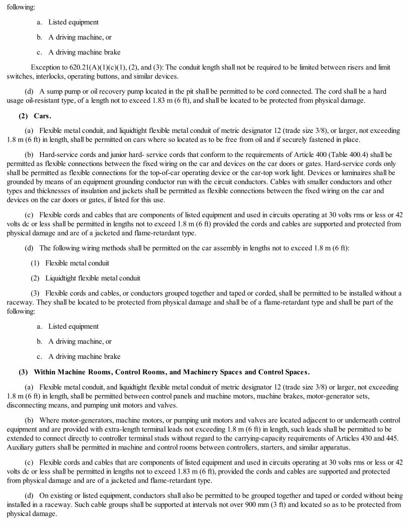
following:
a. Listed equipment
b. A driving machine, or
c. A driving machine brake
Exception to 620.21(A)(1)(c)(1), (2), and (3): The conduit length shall not be required to be limited between risers and limitswitches, interlocks, operating buttons, and similar devices.
(d) A sump pump or oil recovery pump located in the pit shall be permitted to be cord connected. The cord shall be a hardusage oil-resistant type, of a length not to exceed 1.83 m (6 ft), and shall be located to be protected from physical damage.
(2) Cars.
(a) Flexible metal conduit, and liquidtight flexible metal conduit of metric designator 12 (trade size 3/8), or larger, not exceeding1.8 m (6 ft) in length, shall be permitted on cars where so located as to be free from oil and if securely fastened in place.
(b) Hard-service cords and junior hard- service cords that conform to the requirements of Article 400 (Table 400.4) shall bepermitted as flexible connections between the fixed wiring on the car and devices on the car doors or gates. Hard-service cords onlyshall be permitted as flexible connections for the top-of-car operating device or the car-top work light. Devices or luminaires shall begrounded by means of an equipment grounding conductor run with the circuit conductors. Cables with smaller conductors and othertypes and thicknesses of insulation and jackets shall be permitted as flexible connections between the fixed wiring on the car anddevices on the car doors or gates, if listed for this use.
(c) Flexible cords and cables that are components of listed equipment and used in circuits operating at 30 volts rms or less or 42volts dc or less shall be permitted in lengths not to exceed 1.8 m (6 ft) provided the cords and cables are supported and protected fromphysical damage and are of a jacketed and flame-retardant type.
(d) The following wiring methods shall be permitted on the car assembly in lengths not to exceed 1.8 m (6 ft):
(1) Flexible metal conduit
(2) Liquidtight flexible metal conduit
(3) Flexible cords and cables, or conductors grouped together and taped or corded, shall be permitted to be installed without araceway. They shall be located to be protected from physical damage and shall be of a flame-retardant type and shall be part of thefollowing:
a. Listed equipment
b. A driving machine, or
c. A driving machine brake
(3) Within Machine Rooms, Control Rooms, and Machinery Spaces and Control Spaces.
(a) Flexible metal conduit, and liquidtight flexible metal conduit of metric designator 12 (trade size 3/8) or larger, not exceeding1.8 m (6 ft) in length, shall be permitted between control panels and machine motors, machine brakes, motor-generator sets,disconnecting means, and pumping unit motors and valves.
(b) Where motor-generators, machine motors, or pumping unit motors and valves are located adjacent to or underneath controlequipment and are provided with extra-length terminal leads not exceeding 1.8 m (6 ft) in length, such leads shall be permitted to beextended to connect directly to controller terminal studs without regard to the carrying-capacity requirements of Articles 430 and 445.Auxiliary gutters shall be permitted in machine and control rooms between controllers, starters, and similar apparatus.
(c) Flexible cords and cables that are components of listed equipment and used in circuits operating at 30 volts rms or less or 42volts dc or less shall be permitted in lengths not to exceed 1.83 m (6 ft), provided the cords and cables are supported and protectedfrom physical damage and are of a jacketed and flame-retardant type.
(d) On existing or listed equipment, conductors shall also be permitted to be grouped together and taped or corded without beinginstalled in a raceway. Such cable groups shall be supported at intervals not over 900 mm (3 ft) and located so as to be protected fromphysical damage.

(e) Flexible cords and cables in lengths not to exceed 1.8 m (6 ft) that are of a flame-retardant type and located to be protectedfrom physical damage shall be permitted in these rooms and spaces without being installed in a raceway. They shall be part of thefollowing:
(1) Listed equipment
(2) A driving machine, or
(3) A driving machine brake
(4) Counterweight. The following wiring methods shall be permitted on the counterweight assembly in lengths not to exceed 1.8m (6 ft):
(1) Flexible metal conduit
(2) Liquidtight flexible metal conduit
(3) Flexible cords and cables, or conductors grouped together and taped or corded, shall be permitted to be installed without araceway. They shall be located to be protected from physical damage, shall be of a flame- retardant type, and shall be part of thefollowing:
a. Listed equipment
b. A driving machine, or
c. A driving machine brake
(B) Escalators.
(1) Wiring Methods. Flexible metal conduit or liquidtight flexible metal conduit shall be permitted in escalator and moving walkwellways. Flexible metal conduit or liquidtight flexible conduit of metric designator 12 (trade size 3/8) shall be permitted in lengths notin excess of 1.8 m (6 ft).
(2) Class 2 Circuit Cables. Cables used in Class 2 power-limited circuits shall be permitted to be installed within escalators andmoving walkways, provided the cables are supported and protected from physical damage and are of a jacketed and flame- retardanttype.
(3) Flexible Cords. Hard-service cords that conform to the requirements of Article 400 (Table 400.4) shall be permitted asflexible connections on escalators and moving walk control panels and disconnecting means where the entire control panel anddisconnecting means are arranged for removal from machine spaces as permitted in 620.5.
(C) Platform Lifts and Stairway Chairlift Raceways.
(1) Wiring Methods. Flexible metal conduit or liquidtight flexible metal conduit shall be permitted in platform lifts and stairwaychairlift runways and machinery spaces. Flexible metal conduit or liquidtight flexible conduit of metric designator 12 (trade size 3/8)shall be permitted in lengths not in excess of 1.8 m (6 ft).
(2) Class 2 Circuit Cables. Cables used in Class 2 power-limited circuits shall be permitted to be installed within platform liftsand stairway chairlift runways and machinery spaces, provided the cables are supported and protected from physical damage and areof a jacketed and flame-retardant type.
(3) Flexible Cords and Cables. Flexible cords and cables that are components of listed equipment and used in circuitsoperating at 30 volts rms or less or 42 volts dc or less shall be permitted in lengths not to exceed 1.83 m (6 ft) provided the cords andcables are supported and protected from physical damage and are of a jacketed and flame-retardant type."
(Added Coun. J. 9-6-17, p. 55278, Art. I, § 1)
14E-6-625 Electric vehicle charging systems.
The provisions of Article 625 of NFPA 70 are adopted by reference without modification.
(Added Coun. J. 9-6-17, p. 55278, Art. I, § 1)
14E-6-626 Electrified truck parking spaces.

The provisions of Article 626 of NFPA 70 are adopted by reference without modification.
(Added Coun. J. 9-6-17, p. 55278, Art. I, § 1)
14E-6-630 Electric welders.
The provisions of Article 630 of NFPA 70 are adopted by reference without modification.
(Added Coun. J. 9-6-17, p. 55278, Art. I, § 1)
14E-6-640 Audio signal processing, amplification, and reproduction equipment.
The provisions of Article 640 of NFPA 70 are adopted by reference with the following modifications.
1. Revise subsection 640.3(B) to read, with no exceptions or notes:
"Ducts, Plenums, and Other Air-Handling Spaces. Section 300.22(B) shall apply to circuits and equipment installed in ductsspecifically fabricated for environmental air. Section 300.22(C) shall apply to circuits and equipment installed in other spaces used forenvironmental air (plenums)."
2. Revise subsection 640.23 to read:
"Conduit or Tubing. The number of conductors permitted in a single conduit or tubing shall not exceed the percentage fill specifiedin Table 1, Chapter 9."
3. Revise subsection 640.24 to read:
"Wireways, Gutters, and Auxiliary Gutters. The use of metallic wireways, gutters, and auxiliary gutters shall be permitted foruse with audio signal conductors and shall comply with applicable articles with respect to permitted locations, construction, and fill."
(Added Coun. J. 9-6-17, p. 55278, Art. I, § 1)
14E-6-645 Information technology equipment.
The provisions of Article 645 of NFPA 70 are adopted by reference with the following modifications:
1. Revise subsection 645.3(B) to read:
"Plenums. Section 300.22(C) shall apply to wiring and cabling in other spaces used for environmental air (plenums) in or above aninformation technology equipment room."
2. Revise subsection 645.5(E) to read:
"Under Raised Floors. Power cables, communi- cations cables, connecting cables, interconnecting cables, cord-and-plugconnections, and receptacles associated with the information technology equipment shall be permitted under a raised floor, provided thefollowing conditions are met:
(1) The raised floor is of approved construction, and the area under the floor is accessible.
(2) The branch-circuit supply conductors to receptacles or field-wired equipment are in rigid metal conduit, intermediate metalconduit, electrical metallic tubing, metal wireway, surface metal raceway with metal cover, flexible metal conduit, liquidtight flexiblemetal conduit, and associated metallic boxes or enclosures as permitted in Chapter 3. These supply conductors shall be installed inaccordance with the requirements of 300.11.
(3) Ventilation in the underfloor area is used for the information technology equipment room only, except as provided in 645.4(2).The ventilation system shall be so arranged, with approved smoke detection devices, that upon the detection of fire or products ofcombustion in the underfloor space, the circulation of air will cease.
(5)* Openings in the raised floor for cords and cables protect cords and cables against abrasion and minimize the entrance of debrisbeneath the floor.
* Editor's note - As numbered in Coun. J. 9-6-17, p. 55278, § 1. Future legislation will correct the provision if needed.
(6) Cables, other than those covered in 645.5(E)(2) and (E)(3), are one of the following:
a. Listed DP cable having adequate fire- resistant characteristics suitable for use under raised floors of an information technology
equipment room.
b. Interconnecting cables enclosed in a raceway.
c. Equipment grounding conductors
Informational Note: One method of defining fire resistance is by establishing that the cables do not spread fire to the top of the trayin the "UL Flame Exposure, Vertical Tray Flame Test" in UL 1685-2011, Standard for Safety for Vertical-Tray Fire-Propagation andSmoke-Release Test for Electrical and Optical-Fiber Cables. The smoke measurements in the test method are not applicable.
Another method of defining fire resistance is for the damage (char length) not to exceed 1.5 m (4 ft 11 in.) when performing theCSA "Vertical Flame Test - Cables in Cable Trays," as described in CSA C22.2 No. 0.3-M-2001, Test Methods for Electrical Wiresand Cables."
(Added Coun. J. 9-6-17, p. 55278, Art. I, § 1)
14E-6-646 Modular data centers.
The provisions of Article 646 of NFPA 70 are not adopted.
(Added Coun. J. 9-6-17, p. 55278, Art. I, § 1)
14E-6-647 Sensitive electronic equipment.
The provisions of Article 647 of NFPA 70 are adopted by reference without modification.
(Added Coun. J. 9-6-17, p. 55278, Art. I, § 1)
14E-6-650 Pipe organs.
The provisions of Article 650 of NFPA 70 are adopted by reference without modification.
(Added Coun. J. 9-6-17, p. 55278, Art. I, § 1)
14E-6-660 X-ray equipment.
The provisions of Article 660 of NFPA 70 are adopted by reference without modification.
(Added Coun. J. 9-6-17, p. 55278, Art. I, § 1)
14E-6-665 Induction and dielectric heating equipment.
The provisions of Article 665 of NFPA 70 are adopted by reference without modification.
(Added Coun. J. 9-6-17, p. 55278, Art. I, § 1)
14E-6-668 Electrolytic cells.
The provisions of Article 668 of NFPA 70 are adopted by reference without modification.
(Added Coun. J. 9-6-17, p. 55278, Art. I, § 1)
14E-6-669 Electroplating.
The provisions of Article 669 of NFPA 70 are adopted by reference without modification.
(Added Coun. J. 9-6-17, p. 55278, Art. I, § 1)
14E-6-670 Industrial machinery.
The provisions of Article 670 of NFPA 70 are adopted by reference without modification.
(Added Coun. J. 9-6-17, p. 55278, Art. I, § 1)
14E-6-675 Electrically driven or controlled irrigation machines.
The provisions of Article 675 of NFPA 70 are adopted by reference without modification.

(Added Coun. J. 9-6-17, p. 55278, Art. I, § 1)
14E-6-680 Swimming pools, fountains, and similar installation.
The provisions of Article 680 of NFPA 70 are adopted by reference with the following modification:
1. Revise section 680.11 to read:
"Underground Wiring Location. Underground wiring shall be permitted where installed in rigid metal conduit, intermediate metalconduit, rigid polyvinyl chloride conduit, or reinforced thermosetting resin conduit. Underground wiring shall not be permitted under thepool unless this wiring is necessary to supply pool equipment permitted by this article. The minimum cover depths shall be as given inTable 300.5."
(Added Coun. J. 9-6-17, p. 55278, Art. I, § 1)
14E-6-682 Natural and artificially made bodies of water.
The provisions of Article 682 of NFPA 70 are adopted by reference without modification.
(Added Coun. J. 9-6-17, p. 55278, Art. I, § 1)
14E-6-685 Integrated electrical systems.
The provisions of Article 685 of NFPA 70 are adopted by reference without modification.
(Added Coun. J. 9-6-17, p. 55278, Art. I, § 1)
14E-6-690 Solar photovoltaic (PV) systems.
The provisions of Article 690 of NFPA 70 are adopted by reference with the following modification:
1. Revise subsection 690.7(A) by deleting item (3) and the subsequent informational note.
(Added Coun. J. 9-6-17, p. 55278, Art. I, § 1)
14E-6-691 Large-scale photovoltaic (PV) electric power production facility.
The provisions of Article 691 of NFPA 70 are adopted by reference without modification.
(Added Coun. J. 9-6-17, p. 55278, Art. I, § 1)
14E-6-692 Fuel cell systems.
The provisions of Article 692 of NFPA 70 are adopted by reference without modification.
(Added Coun. J. 9-6-17, p. 55278, Art. I, § 1)
14E-6-694 Wind electric systems.
The provisions of Article 694 of NFPA 70 are adopted by reference without modification.
(Added Coun. J. 9-6-17, p. 55278, Art. I, § 1)
14E-6-695 Fire pumps.
The provisions of Article 695 of NFPA 70 are adopted by reference with the following modifications:
1. Insert new section 695.3 to read:
"Power Sources for Electric Motor-Driven Fire Pumps. Electric motor-driven fire pumps shall have a reliable source of powerin conformance with 695.3(A) and (B).
All primary sources shall have a high degree of reliability and be capable of carrying indefinitely the sum of the locked-rotor currentof the fire pump motor(s) and the full-load current of the associated fire pump controller accessory equipment. These power sources,where required, shall be arranged so that a fire at one source will not cause an interruption at the other source.
Buildings having no required emergency system or only a System III emergency system, shall not be required to have a secondary

source of power for the fire pump.
Informational Note: See Table 700.5 for Emergency Systems Required.
(A) Primary Source. Primary power shall be supplied by a separate, independent service with no disconnect, other than at the firepump controller, from one of the following sources:
(1) Utility Service. Power shall be provided by a separate and independent utility service or, where special permission isobtained in writing from the authority having jurisdiction, an approved off-site primary electrical generating facility in commonownership with the building location of fire pump installation.
(2) On-Site Generation. Power shall be supplied by an approved primary power on-site generator conforming to the following:
(a) The generator room and associated main distribution room shall be enclosed in separate rooms having 3-hour fire ratedconstruction.
(b) All openings into these rooms shall be protected by 3 hour (A-label) opening protective assemblies.
(c) These rooms shall not be below grade.
(d) These rooms shall be used for no other purpose than the primary generation and distribution of power.
(e) If stored fuel is used there shall be kept available a 4-hour reserve of fuel at all times.
(B) Secondary Power. Secondary power shall be in accordance with 695.4(B) and be supplied as follows:
(1) Where Emergency System II is Required. The secondary source shall be as stated below in (a), (b), (c) and (d).
(a) Where the normal building source is common to the Emergency System II auxiliary source, no secondary power shall berequired for the fire pump.
(b) Where the Emergency System II is served by two independent utility sources, the secondary source shall be that sourcewhich is not common to the primary fire pump source.
(c) In high rise buildings under 91 m (300 ft) in height not meeting 695.3(B)(1)(a), the secondary source shall be from anemergency source other than the source serving the fire pump.
(d) In high rise buildings 91 m (300 ft) or greater in height, the secondary source shall be from an on-site generator inconformance with 700.31 and 701.16.
Informational Note: See Table 700.5 for Emergency Systems Required.
(2) Where an Emergency System I is Required. The secondary source shall be from an approved on-site generatorconforming to the requirements of 700.20, 700.50(1) and 701.16.
Informational Note: See Table 700.5 for Emergency Systems Required.
(3) Multi-Building Campus-Style Complexes with Fire Pumps. Where primary sources as described in 695.3(A) are notpracticable and with special permission, two or more feeder sources shall be permitted as one power source where such feedersources are connected to or are derived from separate utility services. The connection(s), overcurrent protective device(s), anddisconnecting means for such feeders shall meet the requirements in 695.4(B)(1) or (B)(2), as applicable.
(4) Conditions. Whenever a secondary source is required by 695.3(B)(1) or (B)(2), all related following conditions shall be met:
(a) In addition to the required connected emergency loads, the generator, or other emergency source where allowed, is sized tocarry indefinitely the sum of the locked-rotor current of the fire pump motor(s) and the full-load current of the associated fire pumpcontroller accessory equipment.
(b) The fire pump feeder is served by a disconnect switch separate from all required emergency loads.
(c) The fire pump feeder is protected by overcurrent protection sized to carry indefinitely the sum of the locked-rotor current ofthe fire pump motor(s) and the full load current of the associated fire pump controller accessory equipment.
(d) The disconnect serving the fire pump shall be lockable in the closed position and be supervised as in 695.4(B)(5).
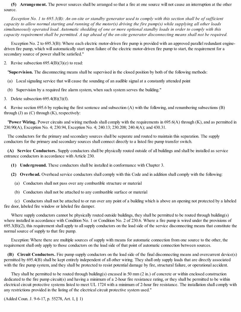
(5) Arrangement. The power sources shall be arranged so that a fire at one source will not cause an interruption at the othersource.
Exception No. 1 to 695.3(B): An on-site or standby generator used to comply with this section shall be of sufficientcapacity to allow normal starting and running of the motor(s) driving the fire pump(s) while supplying all other loadssimultaneously operated load. Automatic shedding of one or more optional standby loads in order to comply with thiscapacity requirement shall be permitted. A tap ahead of the on-site generator disconnecting means shall not be required.
Exception No. 2 to 695.3(B): Where each electric motor-driven fire pump is provided with an approved parallel redundant engine-driven fire pump, which will automatically start upon failure of the electric motor-driven fire pump to start, the requirement for asecondary source of power shall be satisfied."
2. Revise subsection 695.4(B)(3)(e) to read:
"Supervision. The disconnecting means shall be supervised in the closed position by both of the following methods:
(a) Local signaling service that will cause the sounding of an audible signal at a constantly attended point
(b) Supervision by a required fire alarm system, when such system serves the building."
3. Delete subsection 695.4(B)(3)(f).
4. Revise section 695.6 by replacing the first sentence and subsection (A) with the following, and renumbering subsections (B)through (J) as (C) through (K), respectively:
"Power Wiring. Power circuits and wiring methods shall comply with the requirements in 695.6(A) through (K), and as permitted in230.90(A), Exception No. 4; 230.94, Exception No. 4; 240.13; 230.208; 240.4(A); and 430.31.
The conductors for the primary and secondary sources shall be separate and routed to maintain this separation. The supplyconductors for the primary and secondary sources shall connect directly to a listed fire pump transfer switch.
(A) Service Conductors. Supply conductors shall be physically routed outside of all buildings and shall be installed as serviceentrance conductors in accordance with Article 230.
(1) Underground. These conductors shall be installed in conformance with Chapter 3.
(2) Overhead. Overhead service conductors shall comply with this Code and in addition shall comply with the following:
(a) Conductors shall not pass over any combustible structure or material
(b) Conductors shall not be attached to any combustible surface or material
(c) Conductors shall not be attached to or run over any point of a building which is above an opening not protected by a labeledfire door, labeled fire window or labeled fire damper.
Where supply conductors cannot be physically routed outside buildings, they shall be permitted to be routed through building(s)where installed in accordance with Condition No. 1 or Condition No. 2 of 230.6. Where a fire pump is wired under the provisions of695.3(B)(2), this requirement shall apply to all supply conductors on the load side of the service disconnecting means that constitute thenormal source of supply to that fire pump.
Exception: Where there are multiple sources of supply with means for automatic connection from one source to the other, therequirement shall only apply to those conductors on the load side of that point of automatic connection between sources.
(B) Circuit Conductors. Fire pump supply conductors on the load side of the final disconnecting means and overcurrent device(s)permitted by 695.4(B) shall be kept entirely independent of all other wiring. They shall only supply loads that are directly associatedwith the fire pump system, and they shall be protected to resist potential damage by fire, structural failure, or operational accident.
They shall be permitted to be routed through building(s) encased in 50 mm (2 in.) of concrete or within enclosed constructiondedicated to the fire pump circuit(s) and having a minimum of a 2-hour fire resistance rating, or they shall be permitted to be withinelectrical circuit protective systems listed to meet UL 1724 with a minimum of 2-hour fire resistance. The installation shall comply withany restrictions provided in the listing of the electrical circuit protective system used."
(Added Coun. J. 9-6-17, p. 55278, Art. I, § 1)

CHAPTER 14E-7SPECIAL CONDITIONS
14E-7-700 Emergency systems.
14E-7-701 Legally required standby generator systems.
14E-7-702 Optional standby systems.
14E-7-705 Interconnected electric power production sources.
14E-7-706 Energy storage systems.
14E-7-708 Critical operations power systems (COPS).
14E-7-710 Stand-alone system.
14E-7-712 Direct current microgrids.
14E-7-720 Circuits and equipment operating at less than 50 volts.
14E-7-725 Class 1, class 2, and class 3 remote- control, signaling, and power-limited circuits.
14E-7-727 Instrumentation tray cable: Type ITC.
14E-7-728 Fire-resistive cable systems.
14E-7-750 Energy management systems.
14E-7-760 Fire alarm systems.
14E-7-770 Optical fiber cables and raceways.
14E-7-700 Emergency systems.
The provisions of Article 700 of NFPA 70 are not adopted. The following language is adopted as Article 700:
"700 Emergency Systems
Part I. General
700.1.Scope. The purpose of this article is to provide details for installation of required exit and emergency illumination systems inall buildings, new and existing.
The provisions of Article 700 are intended to provide a reasonably reliable alternate source of electrical power upon the failure of thenormal source of supply. It is impossible to list all of the various means of accomplishing the desired results. Article 700 is intended toset a minimum standard for such installations.
Informational Note No. 1: For further information regarding wiring and installation of emergency systems in health care facilities, seeArticle 517.
Informational Note No. 2: For further information regarding performance and maintenance of emergency systems in health carefacilities, see NFPA 99-2015, Health Care Facilities Code.
Informational Note No. 3: For specification of locations where emergency lighting is considered essential to life safety, see NFPA101-2015, Life Safety Code.
Informational Note No. 4: For further information regarding performance of emergency and standby power systems, see NFPA110-2013, Standard for Emergency and Standby Power Systems.
700.2. Definitions.
Auxiliary Source of Current Supply. The auxiliary source of current supply shall be another independent source of current supply,isolated from the normal source, either from the utility, an on-site generator, an inverter, or unit batteries where allowed in this article.
Emergency Lighting (Illumination) Systems. Emergency lighting systems shall be lighting systems required by this chapter

which supplement the general lighting system.
Exit Lighting Systems. Exit lighting systems shall be those electrical systems which supply electricity to required exit, directional,stairway and fire escape signs.
Informational Note: See Sections 13-160-700 through 13-160-820 of the Chicago Building Code for location and type.
Emergency Systems. Emergency systems are intended to automatically supply illumination, power, or both, to designated areas andequipment in the event of failure of the normal supply or in the event of accident to elements of a system intended to supply, distribute,and control power and illumination essential for safety to human life.
Final Reserve Source of Current Supply. The final reserve source of current supply shall be an approved battery source, on-sitegenerator installed in accordance with Article 701, or an approved on-site inverter system.
Normal Source of Current Supply. The normal source of current supply is that supply which furnishes electrical energy forgeneral illumination and power purposes.
Relay, Automatic Load Control. A device used to set normally dimmed or normally-off switched emergency lighting equipment tofull power illumination levels in the event of a loss of the normal supply by bypassing the dimming/switching controls, and to return theemergency lighting equipment to normal status when the device senses the normal supply has been restored.
Informational Note: See ANSI/UL 924, Emergency Lighting and Power Equipment, for the requirements covering automatic loadcontrol relays.
700.3General. The provisions of this article shall be in addition to or amendatory of those set forth in Chapters 1 through 4 of thisCode. Emergency and exit lighting systems shall not be intermingled with any other wiring system in the building except as otherwiseallowed in this article.
700.4Plan Submittal Procedure. No work shall start on the exit and emergency lighting systems before approved by the authorityhaving jurisdiction.
In addition to any other information required by the authority having jurisdiction, the plans shall indicate:
(a) The location of all exit and emergency lights on scaled floor plans of a scale not less than 1/8 in. = 1 ft.
(b) The location of all normal lights in areas with exit and emergency lights.
(c) A single line drawing of the emergency service and distribution showing sizes of conduit, conductors, switches, and overcurrentdevices.
(d) Connected load of all branch circuit panels.
(e) Information relative to generators as required in Section 701.6.
Exception No. 1: In new buildings, when the first tenant is entering a space, it shall not be necessary to submit the informationrequired in (c) through (e) above, provided each plan indicates the reviewed plan number on which the information was previouslysubmitted.
Exception No. 2: It shall be the responsibility of the plan applicant to determine the adequacy of an existing emergency service anddistribution. The details of this service and distribution, in (c) above, need not be shown when it is stated by the submitter that theexisting emergency system is in conformance with this chapter. However, the drawings shall indicate the measured connected load forthe affected emergency branch circuit panels, and the connected load for all additional circuits being altered or installed.
Part II. Emergency System Requirements
700.5Type of Emergency Systems Required. The type of emergency system (I, II, or III) provided in buildings shall be asindicated in Table 700.5, except an existing occupancy with a type III or better system permitted under an earlier version of this Codemay continue to use that system. All required emergency lights, exit, directional, stairway and fire escape signs in these buildings shallbe supplied from the emergency system as required in this Article.
Table 700.5. Emergency System Type Required - By Use9, 10

Building Use /Type
OccupancyClass*
Application Provisions
(Capacity, Height, Area)
System TypeI II III
Residential
Hotels / Motels A Two floor or more, ormore than 20 persons X
Non-transientResidential A
5 or more dwellingunits - see Articles560 and 570
X
Non-transientResidential A
dormitories, grouphomes, fraternity andsorority houses - twofloors or more, ormore than 20 persons
X
Non-transientResidential 1
A Over 80 feet but lessthan 300 feet in height
X1,6
Non-transientResidential 1
A 300 feet or more inheight
X6
Single RoomOccupancy A See Chapter 13-206
** X
Transient Residential ATwo floors or more,or more than 20persons
X
Institutional
Ambulatory HealthCare Facilities B, E See Article 517. X5
DayCare orChildCareCenter
Institutionalor 24 Hr. B, C-3
2 floors or more, ormore than 20 persons,or day care centersthat operate between9 p.m. and 6 a.m.
X
Type IIISchool C-3 See Chapter 13-56 ** X
Homes for the Aged orChildren B
Two floors or moreor more than 20persons
X
Hospitals BContaining operating,delivery, oremergency rooms
X
Hospitals B Other than above X5
Jails BTwo floors or more,or more than 20persons
X
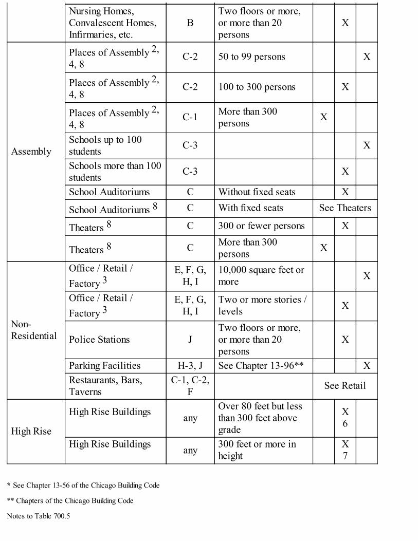
Nursing Homes,Convalescent Homes,Infirmaries, etc.
BTwo floors or more,or more than 20persons
X
Assembly
Places of Assembly 2,4, 8
C-2 50 to 99 persons X
Places of Assembly 2,4, 8
C-2 100 to 300 persons X
Places of Assembly 2,4, 8
C-1 More than 300persons X
Schools up to 100students C-3 X
Schools more than 100students C-3 X
School Auditoriums C Without fixed seats X
School Auditoriums 8 C With fixed seats See Theaters
Theaters 8 C 300 or fewer persons X
Theaters 8 C More than 300persons X
Non-Residential
Office / Retail /Factory 3
E, F, G,H, I
10,000 square feet ormore X
Office / Retail /Factory 3
E, F, G,H, I
Two or more stories /levels X
Police Stations JTwo floors or more,or more than 20persons
X
Parking Facilities H-3, J See Chapter 13-96** XRestaurants, Bars,Taverns
C-1, C-2,F See Retail
High Rise
High Rise Buildings any
Over 80 feet but lessthan 300 feet abovegrade
X6
High Rise Buildings any 300 feet or more in
heightX7
* See Chapter 13-56 of the Chicago Building Code
** Chapters of the Chicago Building Code
Notes to Table 700.5

1 All existing and newly constructed buildings having dwelling units, more than 80 feet above grade shall provide an approved, on-siteauxiliary source of current supply for the egress lighting and exit signs.
2 For the purposes of this Table, Places of Assembly (except as indicated for schools) shall include, but shall not be limited to, locationssuch as:
Airport TerminalsAuditoriumsAssembly HallsBanquet Halls
Churches /ChapelsClub HousesDance HallsExhibition Halls
GymnasiumsLibrariesLodge HallsMuseums
Parish HallsSwimming Pools
3 For the purposes of this table, Office / Retail / Factory shall include, but shall not be limited to, locations such as:
AutomobileAgenciesBakeriesBanksBarber ShopsBeauty ParlorsBilliard Parlors
BookstoresBowling AlleysBroadcastingStudiosFactoriesFrozen FoodLockersLaboratories
Lumber YardsMeat Packing orProcessingMotor FreightDocksOffice BuildingsPet Shops
PlantsRetail StoresVaultsWarehouses
4 For the purposes of this Table use of any room or space for assembly purposes by less than 50 persons in a building having otheruses, and incidental to such other use, shall be classed as part of the other use and subject to the provisions applicable thereto.
5 The second source of current supply shall be an on-site generator or a battery system.
6 See 700.30.
7 The auxiliary source of current supply shall be from an on-site diesel generator. This shall apply to all buildings 91 m (300 ft) andover unless the building requires a System I under other uses.
8 Any building or space in this category where fixed seating is provided for the public or the occupants of the building during anyperformance or meeting shall be provided with a System I emergency system where having capacity for more than 300 persons andshall be provided with aisle lighting where having capacity for more than 150 persons. In buildings with multiple spaces containing fixedseats, the classification of the Emergency system shall be based on the total number of seats in the building. The aisle lightingrequirement shall be based on the number of seats in each space.
9 Where System III is required, a System I or II may be installed. Where System II is required, a System I may be installed.
10 It is impossible to list each specific type of use and therefore some of the classifications are general. If there is any doubtconcerning a particular building or use, consult the authority having jurisdiction.
700.6 Illumination Required.
(A) General. In general, every portion of a building devoted to the use or accommodation of occupants, including all assemblyrooms, all means of egress leading to the streets, open courts, corridors, stairways, exits, emergency exit stairways, or any other partof the building used by occupants, shall be well illuminated in accordance with requirements for general illumination.
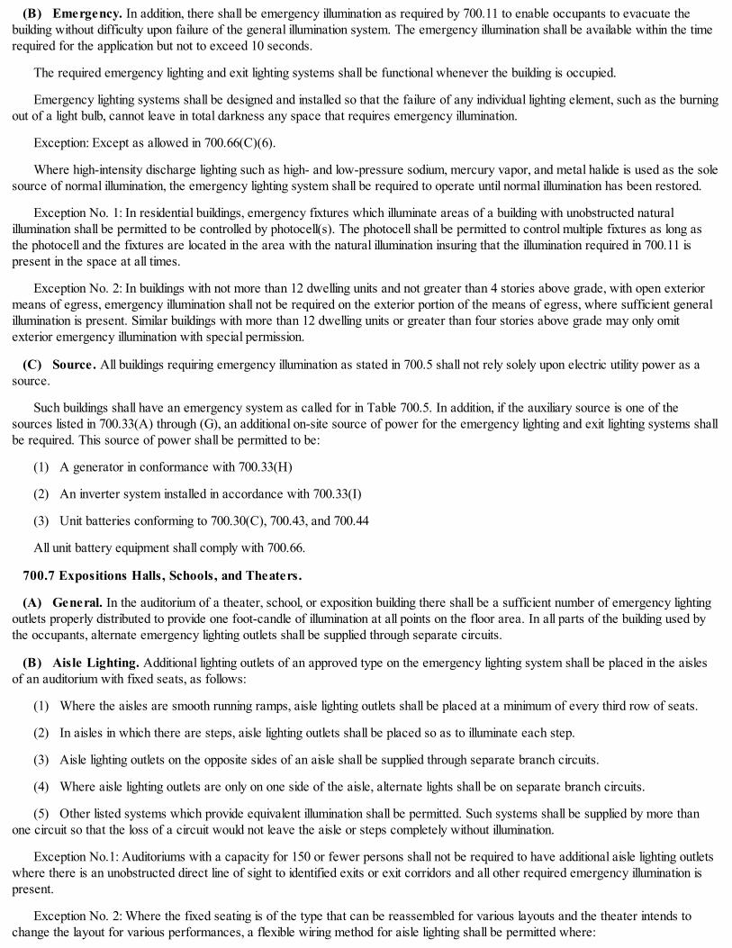
(B) Emergency. In addition, there shall be emergency illumination as required by 700.11 to enable occupants to evacuate thebuilding without difficulty upon failure of the general illumination system. The emergency illumination shall be available within the timerequired for the application but not to exceed 10 seconds.
The required emergency lighting and exit lighting systems shall be functional whenever the building is occupied.
Emergency lighting systems shall be designed and installed so that the failure of any individual lighting element, such as the burningout of a light bulb, cannot leave in total darkness any space that requires emergency illumination.
Exception: Except as allowed in 700.66(C)(6).
Where high-intensity discharge lighting such as high- and low-pressure sodium, mercury vapor, and metal halide is used as the solesource of normal illumination, the emergency lighting system shall be required to operate until normal illumination has been restored.
Exception No. 1: In residential buildings, emergency fixtures which illuminate areas of a building with unobstructed naturalillumination shall be permitted to be controlled by photocell(s). The photocell shall be permitted to control multiple fixtures as long asthe photocell and the fixtures are located in the area with the natural illumination insuring that the illumination required in 700.11 ispresent in the space at all times.
Exception No. 2: In buildings with not more than 12 dwelling units and not greater than 4 stories above grade, with open exteriormeans of egress, emergency illumination shall not be required on the exterior portion of the means of egress, where sufficient generalillumination is present. Similar buildings with more than 12 dwelling units or greater than four stories above grade may only omitexterior emergency illumination with special permission.
(C) Source. All buildings requiring emergency illumination as stated in 700.5 shall not rely solely upon electric utility power as asource.
Such buildings shall have an emergency system as called for in Table 700.5. In addition, if the auxiliary source is one of thesources listed in 700.33(A) through (G), an additional on-site source of power for the emergency lighting and exit lighting systems shallbe required. This source of power shall be permitted to be:
(1) A generator in conformance with 700.33(H)
(2) An inverter system installed in accordance with 700.33(I)
(3) Unit batteries conforming to 700.30(C), 700.43, and 700.44
All unit battery equipment shall comply with 700.66.
700.7 Expositions Halls, Schools, and Theaters.
(A) General. In the auditorium of a theater, school, or exposition building there shall be a sufficient number of emergency lightingoutlets properly distributed to provide one foot-candle of illumination at all points on the floor area. In all parts of the building used bythe occupants, alternate emergency lighting outlets shall be supplied through separate circuits.
(B) Aisle Lighting. Additional lighting outlets of an approved type on the emergency lighting system shall be placed in the aislesof an auditorium with fixed seats, as follows:
(1) Where the aisles are smooth running ramps, aisle lighting outlets shall be placed at a minimum of every third row of seats.
(2) In aisles in which there are steps, aisle lighting outlets shall be placed so as to illuminate each step.
(3) Aisle lighting outlets on the opposite sides of an aisle shall be supplied through separate branch circuits.
(4) Where aisle lighting outlets are only on one side of the aisle, alternate lights shall be on separate branch circuits.
(5) Other listed systems which provide equivalent illumination shall be permitted. Such systems shall be supplied by more thanone circuit so that the loss of a circuit would not leave the aisle or steps completely without illumination.
Exception No.1: Auditoriums with a capacity for 150 or fewer persons shall not be required to have additional aisle lighting outletswhere there is an unobstructed direct line of sight to identified exits or exit corridors and all other required emergency illumination ispresent.
Exception No. 2: Where the fixed seating is of the type that can be reassembled for various layouts and the theater intends tochange the layout for various performances, a flexible wiring method for aisle lighting shall be permitted where:

(1) The aisle lighting system complies with 700.7(B)
(2) All associated aisle lighting cords are listed as "extra- hard usage"
(3) All associated aisle lighting cord plug and receptacle connections are twist lock
(4) All associated aisle lighting cords are of the minimum length needed for flexibility
(5) Additional strain relief is provided around all associated aisle lighting cord and receptacle connections
(6) The point of connection to the permanent emergency system is visibly identified and of the type that will not accept standardstraight blade plugs
A permit and inspection are required for all reconfiguration of seating prior to use.
Informational Note: This flexible allowance for aisle lighting is not intended and shall not be permitted as a permanent wiringmethod.
(C) Additional Locations. In addition to requirements of 700.7(A), emergency lighting shall be provided:
(1) In the projection booth
(2) At the lighting service equipment
(3) At the stage lighting control equipment
(4) In the room that contains the emergency lighting generator or the batteries
700.8Hospitals. Where a System I is required, permanently connected emergency lights and the ungrounded electrical system (ifinstalled) shall be supplied from the final reserve source of current supply in addition to the general lighting in all critical and specialcare areas. The final reserve source of current supply shall be a diesel generator in conformance with 700.33(H).
The emergency lights shall be adequate to illuminate these rooms for their normal use, and shall be completely separate from thegeneral wiring systems. Switches to turn emergency lights "OFF" when a room is not in use shall be permitted to be installed for eachindividual room.
Informational Note: See Article 517 - Health Care Facilities.
700.9Tenant Spaces in Multi-Use or Multi- Space Buildings. Emergency lighting shall be provided within a tenant space, otherthan a dwelling unit, exceeding 93 m2 (1,000 ft2) in any building in which emergency lighting is required.
700.10Emergency Lighting for Passenger Elevators. Unit batteries shall be provided for standby emergency illumination in theelevator car. Immediately after normal car lighting power fails, emergency lighting shall be provided in all elevators in accordance withthe Chicago Building Code.
Informational Note: See the Safety Code for Elevators and Escalators, ASME A17.1 § 2.14.7.1 for further information.
700.11Intensity of Emergency Illumination. In general the required emergency illumination shall provide not less than one foot-candle of illumination on all points of all required areas.
Exception No. 1: As allowed by 13-160-670 or 13-160-680. Upon failure of the normal lighting system the emergency lighting shallbe restored to full brilliance.
Exception No. 2: Where dimming of the emergency lighting below one foot-candle is required, the following shall apply:
(1) Special permission shall be required.
(2) Upon failure of the normal lighting system the emergency lighting shall be restored to full brilliance.
(3) The emergency lighting shall not be dimmed below 1/2 foot-candle.
700.12Capacity of Emergency System. The exit and emergency system, service and feeders shall have a minimum capacity of0.1 watts per square foot, based on the total square foot area of the building.
700.20System I.

(A) Sources of Supply. System I shall consist of three sources of electrical energy supply as follows:
(1) The normal source of current supply
(2) An auxiliary source of current supply totally separate from the normal source
(3) A final reserve source of current supply from batteries, from an on-site generator(s) in conformance with Article 701, or froman on-site inverter
(B) Sequence. System I shall have the following sequence of current supply to the emergency lights and exit signs:
(1) The normal source of current supply
(2) The auxiliary source of current supply upon failure of the normal source of current supply
(3) The final reserve source of current supply upon failure of both the normal and the auxiliary sources of current supply
Informational Note: See Parts III and IV of this Article.
Figure 700.20 Typical System I Emergency System
700.21System II.
(A) Sources of Supply. System II shall consist of two sources of electrical energy supply as follows:
(1) The normal source of current supply
(2) The auxiliary source of current supply
(B) Sequence. System II shall have the following sequence of current supply to the emergency lights and exit signs:
(1) The normal source of current supply
(2) The auxiliary or final reserve source of current supply upon failure of the normal current supply.
(3) For emergency illumination and exit sign purposes, if the auxiliary source of current supply is not one of the sources listed in700.33(H), 700.33(I), 700.30(C), or 700.43 an additional source which complies with 700.6(C) shall be provided.
Informational Note: See Figure 700.21.
Figure 700.21 Typical of Either System II or System III Emergency Systems.

700.22System III. System III shall consist of two sources of current supply as follows:
(1) The normal source of current supply to the structure which shall provide for the general illumination
(2) The second source of current supply shall provide electrical current supply for the emergency lighting and exit lighting systemsand shall be either an auxiliary source in accordance with 700.33(H) or 700.33(I), or approved unit battery equipment in accordancewith 700.43
(3) A transfer switch shall not be required.
Informational Note: See Figure 700.21.
700.23 Transfer Equipment.
(A) General. Transfer equipment, including automatic transfer switches, shall be automatic, identified for emergency use, andapproved by the authority having jurisdiction. Transfer equipment shall be designed and installed to prevent the inadvertentinterconnection of normal and emergency sources of supply in any operation of the transfer equipment. Transfer equipment andelectric power production systems installed to permit operation in parallel with the normal source shall meet the requirements of Article705.
(B) Bypass Isolation Switches. Means shall be permitted to bypass and isolate the transfer equipment. Where bypass isolationswitches are used, inadvertent parallel operation shall be avoided.
(C) Automatic Transfer Switches. Automatic transfer switches shall be electrically operated and mechanically held. Automatictransfer switches, rated 1000 VAC and below, shall be listed for emergency system use.
(D) Use. Transfer equipment for emergency illumination and exit signs shall supply only those loads.
(E) Documentation. The short-circuit current rating of the transfer equipment, based upon the specific overcurrent protectiondevice type and settings protecting the transfer equipment, shall be field marked on the exterior of the transfer equipment.
700.24.Signals. Audible and visual signal devices shall be provided, where practicable, for the purpose described in 700.24(A)through (F).
(A) Malfunction. To indicate malfunction of the emergency source.
(B) Carrying Load. To indicate that the battery is carrying load.
(C) Not Functioning. To indicate that the battery charger is not functioning.
(D) Ground Fault. To indicate a ground fault in solidly grounded wye emergency systems of more than 150 volts to ground andcircuit-protective devices rated 1000 amperes or more. The sensor for the ground-fault signal devices shall be located at, or ahead of,the main system disconnecting means for the emergency source, and the maximum setting of the signal devices shall be for a ground-fault current of 1200 amperes. Instructions on the course of action to be taken in event of indicated ground fault shall be located at ornear the sensor location.
(E) Bypass Isolation. To indicate that the bypass isolation is in the bypass position.
(F) Remote Annunciation. Remote audible and visual annunciation of the transfer switch(es) at a common central mannedlocation shall be installed where the transfer switches are not installed in a location that is manned at all times and the building is open.
Informational Note: For signals for generator sets, see NFPA 110-2013, Standard for Emergency and Standby Power Systems.

700.25 Signs.
(A) Emergency Sources. A sign shall be placed at the service-entrance equipment, indicating type and location of each on-siteemergency power source.
Exception: A sign shall not be required for individual unit equipment as specified in 700.43.
(B) Grounding. Where removal of a grounding or bonding connection in normal power source equipment interrupts the groundingelectrode conductor connection to the alternate power source(s) grounded conductor, a warning sign shall be installed at the normalpower source equipment stating:
WARNING
SHOCK HAZARD EXISTS IF GROUNDING ELECTRODE CONDUCTOR OR BONDING JUMPER CONNECTION INTHIS EQUIPMENT IS REMOVED WHILE ALTERNATE SOURCE(S) IS ENERGIZED.
The warning sign(s) or label(s) shall comply with 110.21(B).
700.26Surge Protection. A listed SPD shall be installed in or on all emergency systems switchboard and panelboards.
700.28Selective Coordination. Emergency system(s) overcurrent devices shall be selectively coordinated with all supply-sideovercurrent protective devices.
Selective coordination shall be selected by a licensed professional engineer or other qualified persons engaged primarily in the design,installation, or maintenance of electrical systems. The selection shall be documented and made available to those authorized to design,install, inspect, maintain, and operate the system.
700.30 High Rise Buildings.
(A) Under 300 Feet In Height. In high rise buildings under 91 m (300 ft) in height, the auxiliary source of current supply to theemergency lighting and exit lighting systems shall be one of the following:
(1) An on-site generator
(2) A battery inverter system in conformance with 700.33(I)
(3) A completely independent utility company primary and either or both:
(a) An on-site generator in conformance with Article 701
(b) A battery inverter system in conformance with 700.33(I)
Exception: Existing high rise buildings containing dwelling units may use unit battery equipment in conformance with the exceptionto 700.30(C) or an approved battery inverter system with a minimum capacity of 90 minutes.
(B) 300 Feet in Height and Over. In buildings 300 feet in height or greater, the auxiliary source of current supply to theemergency lighting and exit lighting systems shall be from an on-site diesel generator in conformance with Article 701.
(C) Dwelling Type Uses. New and existing high rise buildings that contain dwelling units shall have an on-site source of supply,independent from the utility source, for the emergency lighting and exit lighting systems. The on-site source of supply shall be agenerator in conformance with 700.33(H) or an inverter system in conformance with 700.33(I).
Generators shall conform to the following:
(1) High rise buildings under 91 m (300 ft) shall be permitted to have natural gas or diesel fuel as supply and shall comply withArticle 701.
(2) High rise buildings 91 m (300 ft) and over shall be required to have diesel fuel as the supply and shall comply with Article 701.
Exception No.1: Approved unit battery equipment shall be permitted to supply the emergency lighting and exit lighting systems inexisting buildings under 91 m (300 ft) that contain dwelling units, provided they comply with 700.43 and 700.66(C). Buildingsundergoing 60% or more renovation of interior spaces or the electrical system shall not be included in this exception.
Exception No. 2: Approved unit battery equipment shall be permitted for the emergency illumination and exit signs in existingbuildings 91 m (300 ft) and over that contain dwelling units provided that such equipment was installed prior to February 7, 2000.

Informational Note No. 1: The above exceptions do not relieve other Code requirements regarding elevators, sump pumps, firealarms systems, etc.
Informational Note No. 2: See Section 13-76-080 of the Chicago Building Code.
All paths of egress that serve the dwelling units, or are common to both the dwelling units and other spaces in mixed occupancybuildings, shall meet the emergency illumination requirements of this subsection.
Part III. Approved Auxiliary Sources
700.33Approved Auxiliary Sources. The auxiliary source of current supply for all emergency system installations shall complywith any one of the following conditions:
(A) Isolated Plant. When the normal source of current supply is an isolated plant, the auxiliary source of current supply shall befrom an approved overhead or underground service from a utility company.
(B) Overhead Service. The auxiliary source of current supply shall be permitted to be from the same source of current supply asthe normal source of current supply provided:
(1) The normal source of current supply is an overhead service from the utility company and no other utility source is available.
(2) The auxiliary source of current supply is from a different pole and is by separate drop, service conduit, and equipment aswidely separated from the normal source of current supply as physical conditions permit.
(C) Separate Transformers. When the normal lighting and power supply is alternating current from separate transformers:
(1) The auxiliary source of current supply shall be permitted to be from an approved transformer or transformers within thebuilding and supplied from the power service.
(2) The current supply to the transfer switch shall be taken from the first distribution point on the load side of the light and powerservice switches.
(D) Underground Network System. Where the source of current supply is common to both light and power and is a utility-supplied underground, 3 phase, network system fed from two or more generating or substations, the auxiliary source of current supplyshall be permitted to be a separate service from the utility supplied underground network system. A transfer switch shall not berequired.
(E) Spot Network. The auxiliary source of current supply shall be permitted to be a separate service where the source of currentsupply is common to both light and power, and is what is known as a "spot network" having:
(1) Two separate primaries
(2) Two utility company transformers
(3) Utility switchgear necessary to accomplish fully automatic switching in both directions. A transfer switch shall not berequired.
(F) Common Source. Where the source of current supply is common to both light and power and consists of a single utilitycompany primary supplying one or more transformers located on a pole structure or on a pad outside of the building being served, theauxiliary source of current supply shall be taken from the secondary side of the transformer or transformers through a separate set ofservice entrance conductors, a separate service conduit, a service switch and a ground. A transfer switch shall be required.
(G) Building Vault. Where the source of current supply is in a vault located inside of the building being served and the secondaryleads are as short as possible, the emergency auxiliary source of current supply shall be permitted to be a separate service from thevault. A transfer switch shall not be required.
(H) Approved Generator. Where the normal source of current supply is an approved utility company service, the auxiliarysource of current supply shall be permitted to be an on-site generator installed in accordance with Article 701.
(I) Inverter System. Where the normal source of current supply is an approved utility company service, the auxiliary source ofcurrent supply shall be permitted to be an approved on-site inverter complying with the following:
(1) The inverter system shall be listed for emergency system use and have battery capacity to power the entire emergencylighting and exit sign system as follows:

(a) In high rise buildings as required by Section 700.30 for a period of four hours
(b) In places of assembly with an occupancy greater than 1,000 persons for a period of four hours
(c) In all other occupancies for a period of ninety minutes.
(2) The inverter system shall be tested at full load for the rated time at least once per year.
(3) This annual test shall be witnessed by the authority having jurisdiction, and the required inspection fee for this test shall bepaid.
Informational Note: Note that utility supplied auxiliary sources as listed in 700.33(A) through (G) above shall not solely satisfy theemergency illumination requirements of this article. See 700.6(C).
700.43 Approved Unit Battery Equipment.
(A) Approved Unit Battery Equipment. Approved unit battery equipment shall be permitted as the auxiliary source of currentsupply as follows:
(1) The required emergency lighting and exit lighting systems in any building or space where a System III is required
(2) The required emergency lighting and exit lighting systems in any building where a System II is required, other than a high risebuilding which shall comply with 700.30, provided that:
(a) There is sufficient general and, or emergency illumination that is on at all times the building is occupied
(b) The installation, control and maintenance of the emergency system complies with Part V of this article
(3) The required emergency lighting and exit lighting systems in existing high rise residential buildings not over 91 m (300 ft) inheight, provided that:
(a) There is sufficient general and, or emergency illumination that is on at all times the building is occupied
(b) The installation, control and maintenance of the emergency system complies with Part V of this article
(4) The final reserve source for places of assembly in existing buildings where a System I is required.
Informational Note: In all new and existing high rise buildings containing residential type units 91 m (300 ft) in height and greater, adiesel generator is the only acceptable method of supply to the required emergency illumination and exit sign system unless allowed by700.30(C)(Exception No. 2).
Unit battery equipment shall comply with 700.66(C).
Informational Note: Nothing in this Code prohibits battery backed up exit signs as long as they are installed in conformance with theabove requirements and conform to relevant sections of the Building Code.
700.44 Battery Systems as Back-up Source for Exit Signs. Where no generator or battery inverter system is used, the back-upsource of current supply for exit signs shall be approved unit battery exit signs conforming to Section 700.66 and Sections 13-160-740through 13-160-800 of the Chicago Building Code.
Part IV. Final Reserve Source of Current Supply
700.50Approved Final Reserve Source of Current Supply. In all cases the final reserve source of current supply shall be oneof the following and shall be able to operate at full load for a minimum of 4 hours:
(1) An approved on-site generator in conformance with Article 701
(2) An approved battery system
(3) An approved inverter system
Part V. Installation and Control of Systems
700.59Installation and Control of Systems. The following shall be required for installation and control of systems:
(1) Buildings that are closed and not occupied for a portion of the day shall be permitted to have the emergency lighting and exit

lighting systems controlled by a manually operable non-locking type switch(es) located only in the main lobby or lobbies, entrances, orentrance stairways.
(2) Where there is more than one main lobby, entrance or entrance stairway switches which turn all exit and emergency lights"ON" shall be permitted to be installed in each location. A switch to turn these lights "OFF" shall be permitted to be installed in only oneof these locations.
(3) In high rise buildings with a fire command panel, the switch referred to in this section shall be located in or adjacent to the firecommand panel.
(4) In buildings without a fire command panel, the switch(es) shall be identified and the "OFF" switch(es) shall be installed behindlocked break glass covers.
700.60Switches Allowed. Only the following switches shall be permitted in the emergency lighting and exit lighting systems:
(1) The service switch
(2) Feeder switch(es) (if required)
(3) The required transfer switch(es)
(4) The lobby control switch(es)
700.61 Dimmer and Relay Systems. A dimmer or relay system containing more than one dimmer or relay and listed for use inemergency systems shall be permitted to be used as a control device for energizing emergency lighting circuits. Upon failure of normalpower, the dimmer or relay system shall be permitted to selectively energize only those branch circuits required to provide minimumemergency illumination. All branch circuits supplied by the dimmer or relay system cabinet shall comply with the wiring methods ofArticle 700.
700.62 Circuit Breakers and Fuses.
(A) Circuit Breakers. Circuit breakers are switching devices and shall be permitted to be used for service, feeder, or branchcircuit overcurrent protection only under the following conditions:
(1) Standard single pole circuit breakers, prominently identified as required by 700.63, used for branch circuit protection where abranch circuit panel is installed in an electrical closet or switchboard room accessible only to qualified persons
(2) Single pole, key-operated circuit breakers used for emergency branch circuit protection in any panel location
(3) Standard circuit breakers may be used where the emergency branch circuit distribution panel feeds only three-phase loadswhich are required to be on the emergency system
(4) Standard circuit breakers with approved lock-on devices shall be permitted for branch circuits where supplying emergencyillumination and exit signs and unit battery equipment complying with 700.66
(B) Fuses. Standard fused switch equipment shall be permitted to be used for feeder overcurrent protection when installed inlocked room accessible only to qualified persons and identified in accordance with 700.63.
700.63 Separate Wiring Systems.
(A) Identification. All boxes and enclosures (including transfer switches, generators, transformers and power panels) foremergency circuits shall be permanently marked so they will be readily identified as a component of an emergency circuit or system.The legends for all branch circuit and feeder distribution panels shall be marked to identify the loads they serve.
(B) Wiring Separation. Emergency lighting and exit lighting system feeders and branch circuits, shall be completely separate andindependent wiring systems from all other electrical systems starting from the source of current supply to the last lighting outlet on thesystems.
Emergency illumination and exit sign equipment branch circuit conductors shall be permitted to occupy the same raceway andshare the same branch circuit. These branch circuits shall not be part of multiwire branch circuits.
Emergency unit battery equipment as allowed in 700.43 shall be permitted to share general lighting branch circuits when inconformance with 700.66. Emergency battery unit wiring shall conform to Section 700.66(C).
(C) Wiring Design and Location. Emergency wiring circuits shall be designed and located to minimize the hazards that might

cause failure due to flooding, fire, icing, vandalism, and other adverse conditions.
No apparatus or lighting outlets other than those specified shall be permitted to be connected to exit and emergency lightingsystems. Branch circuits shall be allowed a maximum of 15 emergency lighting outlets per branch circuit.
(D) Fire Protection. In new buildings and buildings undergoing 60% or greater remodeling of interior spaces or the electricalsystem, the emergency lighting and exit lighting systems shall meet the following additional requirements in (D)(1) through (D)(3) in thefollowing occupancies:
(1) Assembly occupancies for not less than 1000 persons
(2) High rise buildings
(3) Health care occupancies where persons are not capable of self- preservation
(4) Educational occupancies with more than 300 occupants
(1) Feeder-Circuit Wiring. Feeder-circuit wiring shall meet one of the following conditions:
(1) Be installed in spaces or areas that are fully protected by an approved automatic fire suppression system
(2) Be a listed electrical circuit protective system with a minimum 2-hour fire rating
Informational Note No. 1: Electrical circuit protective systems could include but not be limited to thermal barriers or aprotective shaft and are tested to UL 1724 Fire Tests for Electrical Circuit Protection Systems.
Informational Note No. 2: The listing organization provides information for electrical circuit protective systems on properinstallation requirements to maintain the fire rating.
(3) Be a listed fire-resistive cable system installed in a metal raceway and supported according to listing requirements
Informational Note No. 1: Fire- resistive cables are tested to ANSI/UL 2196, Tests for Fire-Resistive Cables.
Informational Note No. 2: The listing organization provides information for electrical circuit protective systems on properinstallation requirements to maintain the fire rating.
(4) Be protected by a listed fire-rated assembly that has a minimum fire rating of 2 hours and contains only emergency wiringcircuits
(5) Be encased in a minimum of 50 mm (2 in.) of concrete
(6) Be a cable installed in a metallic raceway listed to maintain circuit integrity for a minimum of 2 hours when installed inaccordance with the listing requirements.
(2) Feeder-Circuit Equipment. Equipment for feeder circuits (including transfer switches, transformers, and panel-boards)shall be located either in spaces fully protected by approved automatic fire suppression systems (including sprinklers, carbon dioxidesystems) or in spaces with a 2-hour fire resistance rating.
(3) Generator Control Wiring. Control conductors installed between the transfer equipment and the emergency generator shallbe kept entirely independent of all other wiring and shall meet the conditions of 700.63(D)(1).
700.64Other Loads. The following loads shall be permitted to be connected to separate emergency branch circuits.
(1) The loads required to be connected to the high rise emergency system
Informational Note: See relevant sections of the Chicago Building Code related to high rise emergency requirements.
(2) Emergency voice communication systems that are specifically designed to be used for issuing instructions during emergencyconditions
(3) The loads required for hospital emergency systems.
Informational Note: See Article 517.
(4) Required fire alarm systems.

Informational Note: See Article 760.
(5) Loads required or allowed elsewhere in this Code to be on the emergency system.
700.65Existing Multifamily Dwelling Unit Buildings. For existing multifamily dwelling unit buildings:
(1) Service conductors having an ampacity of 40 amperes shall be permitted for single-phase, three-wire services that serve nomore than four 15-ampere branch circuits.
(2) Where the building is 4 stories or less in height and is served directly by vertical front and rear stairwells, all existing stairwelllighting outlets shall be permitted to be supplied from the emergency service. Corridor emergency lighting outlets shall be in addition tothe general illumination.
(3) Other loads such as laundry outlets, heating plants, sump pumps, garage and basement lighting shall not be permitted to besupplied from the emergency service.
(4) Emergency lights shall be permitted to be controlled by photocell switches. Time clocks shall not be permitted.
(5) High rise multifamily dwelling unit buildings shall be in conformance with 700.30.
700.66Approved Unit Battery Equipment and Battery Systems. The following shall apply to batteries and battery systems foremergency systems:
(A) Dry Cell Batteries. Dry cell batteries shall not be permitted on any emergency lighting system.
(B) Battery and Battery Inverter Systems. Battery and battery inverter systems, regardless of voltage, shall be listed foremergency lighting use.
(C) Unit Battery Equipment.
(1) Listing and Labeled. All unit batteries shall be listed and labeled as emergency luminaire equipment. Individual unitequipment for required standby emergency illumination shall consist of the following:
(a) A rechargeable battery
(b) A battery charging means
(c) Provisions for one or more lamps
(d) A relaying device arranged to automatically energize the lamps upon failure of the supply to the unit equipment
(e) Batteries of suitable rating and capacity to supply and maintain not less than 87-1/2 percent of the nominal battery voltagefor the total lamp load associated with the unit for a period of at least 90 minutes
(f) Acid or alkali storage batteries designed and constructed to meet the requirements of emergency service.
(2) Provisions. The unit equipment shall be provided with:
(a) A test switch for checking the operating conditions of the unit.
(b) A pilot light to indicate when the battery charger is functioning, when tied to the normal source. Functioning of the batterycharger is intended to mean the presence of charging voltage.
(c) The pilot light shall not be marked "READY" to indicate power available.
(3) Enclosure. The unit battery and lamp housing shall be made of metal. In wet or corrosive locations housings that are listedfor emergency use and suitable for the environment shall be permitted to be made of other materials.
Exception: Decorative plastic enclosures over metal housings shall be permitted.
(4) Wiring. The wiring shall comply with the following:
(a) Unit equipment shall be permanently fixed in place and supplied with an approved metallic raceway.
(b) Flexible cord and plug connections shall not be permitted.

(c) The branch circuit feeding the unit equipment shall be the same branch circuit as that serving the normal illumination, or(emergency illumination where present) in the area and connected ahead of any local switches.
(d) The branch-circuit device shall be a type S plug fuse, a circuit breaker of the key operated type, or shall be provided with alocking device to prevent inadvertent opening of the circuit and shall comply with 700.63.
(e) The panel directory shall be prominently marked to identify the circuits that supply the unit batteries.
(f) Where there is a separate and uninterrupted area supplied by a minimum of 3 normal lighting circuits, a separate branchcircuit for unit batteries shall be permitted, provided the circuit originates from the same panelboard as that of the normal lightingcircuits and is either a type S plug fuse, a circuit breaker of the key operated type, or a circuit breaker provided with a lock on feature.
(g) No more than three lamps shall be permitted to be supplied from one-unit battery.
(h) When a remote lamp is connected to a unit battery, the wiring shall be in an approved metallic raceway and shall beindependent of all other wiring and equipment. The wiring shall be limited to 4.57 m (15 ft) and shall not enter the same raceway, box,or cabinet with other wiring.
Exception: Wiring in a length greater than 4.57 m (15 ft) shall be permitted where it can be shown that by increased wire size,the voltage drop from the battery to the lamp will still allow the lamp to operate at normal brilliance.
(5) Location. Luminaires shall be so located as to provide the illumination required in 700.6 upon failure of the normal lightingservice; these lights shall not be required to be "ON" until failure occurs. In general, one luminaire shall be provided for each 214 m2
(2,300 ft2) of open floor area. Where this number of luminaires does not provide illumination of all areas leading to points of egress,additional luminaires shall be installed.
(6) Lamp Output. Each lamp shall provide a minimum of 300 lumen output. Single lamps connected to unit batteries that providethe required illumination and are maintained in accordance with subsection (7) below shall be permitted in areas less than 214 m2
(2300 ft2).
(7) Maintenance. Unit batteries shall be maintained by qualified maintenance personnel and the following records shall bemaintained:
(a) The manufacturer shall supply with each unit battery a complete set of instructions for the operation and maintenance ofthe equipment.
(b) The date of original installation and of subsequent battery replacements shall be posted conspicuously on the batterycontainer.
(c) Each unit shall be tested annually.
(d) There shall be a water level indicator where applicable and the water shall be checked monthly.
(e) A readily available log of these inspections shall be maintained on a card attached to the unit battery. The card shall containthe name and address of the responsible maintenance personnel that performed the testing required in (c) and (d) of this subsection.
700.67Generators. On-site generators are recognized as an approved source of current supply for Emergency Systems I, II, andIII. On-site generator(s) used as a current supply for emergency systems shall comply with the requirements of Article 701.
700.68 Tests and Maintenance.
(A) Conduct or Witness Test. The authority having jurisdiction shall conduct or witness a test of the complete system uponinstallation and periodically afterward.
(B) Tested Periodically. Systems shall be tested annually or more frequently on a schedule acceptable to the authority havingjurisdiction to ensure the systems are maintained in proper operating condition.
(C) Maintenance. Emergency system equipment shall be maintained in accordance with manufacturer instructions and industrystandards. These instructions shall be kept on-site and made available to the authority having jurisdiction upon request.
(D) Written Record. A written record shall be kept on such tests and maintenance, maintained on the premises for not less than10 years, and made available to the authority having jurisdiction upon request.

(E) Testing Under Load. Means for testing all emergency lighting and power systems during maximum anticipated loadconditions shall be provided.
Informational Note 1: For information on testing and maintenance of emergency power supply systems (EPSSs), see NFPA 110-2013, Standard for Emergency and Standby Power Systems.
Informational Note 2: See 700.66(C)(7).
700.69Special Provisions for Special Circumstances. The provision of 700.1 thru 700.67 are not intended to limit or inhibit theengineering ingenuity of engineers or contractors in laying out such installations.
Where it can be demonstrated that an alternate design of emergency systems will provide an equivalent or greater level of safetyand reliability than that intended by Article 700, the authority having jurisdiction is empowered to grant special permission for alternateemergency systems in lieu of the specifically required systems. The final determination of equivalency, in all cases, shall be made bythe authority having jurisdiction."
(Added Coun. J. 9-6-17, p. 55278, Art. I, § 1)
14E-7-701 Legally required standby generator systems.
The provisions of Article 701 of NFPA 70 are adopted by reference with the following modifications:
1. Revise section 701.3 to read:
"Tests and Maintenance
(A) Initial Test. A 4-hour full load test based on the rating of the generator shall be performed when a generator(s) is firstinstalled. This test shall be witnessed by the authority having jurisdiction, and the required inspection fee shall be paid prior to the testbeing performed.
(B) Annual Test. The generator shall be tested annually for a period of at least one hour under heavy load. This test shall bewitnessed by the authority having jurisdiction, and the required inspection fee shall be paid prior to the test being performed.
(C) Monthly Tests. Each generator installation shall be tested monthly under load conditions. A log shall be maintained of thesetests. The log shall record the following:
(a) Date and time of day
(b) Voltage and ampere reading (load)
(c) Running time reading at the start of test
(d) Running time reading at the end of the test
(e) Any abnormalities discovered, and other significant data
For testing purposes, a transfer switch(es) shall be provided with a "time-delay on return to normal" which will keep the enginegenerator running for a minimum of 20 minutes under load once a transfer to the generator has occurred.
(D) Maintenance. Legally required standby system equipment shall be maintained in accordance with manufacturer instructionsand industry standards. These instructions shall be kept on-site and made available to the authority having jurisdiction upon request.
(E) Written Record. A written record shall be kept on such tests and maintenance, maintained on the premises for not less than10 years, and made available to the authority having jurisdiction upon request.
(F) Testing Under Load. Means for testing legally required standby systems under load shall be provided.
Informational note: For information on testing and maintenance of emergency power supply systems (EPSSs), see NFPA 110-2013,Standard for Emergency and Standby Power Systems."
2. Insert new section 701.8 to read:
"Signal Annunciator. A storage-battery powered remote annunciator shall be installed outside of the generator room in a locationreadily observed by operating personnel at a regular work station. In addition, unless a regular work station is continuously manned, anappropriately labeled audible and visual signal shall be installed at a manned location. The remote annunciator panel shall include a

voltage meter and a lamp test function and shall be permitted to have an alarm silencing switch and pilot light to indicate alarmsilenced. In addition to the signals described in 701.6 (A), (B), (C) and (D) there also shall be a signal to indicate when the generator isnot in the automatic position."
3. Insert new section 701.9 to read:
"Plans Required. Complete and detailed plans and specifications of all emergency generators shall be submitted to the authorityhaving jurisdiction for review before any construction work is started. These plans shall include the following:
(1) A single line drawing of the complete emergency and/or essential electrical system. The drawing shall include all components ofthe system(s) including utility source(s), generator(s), transfer switch(es), feeder distribution panel(s), and branch circuit panelboard(s).
(2) A floor or site plan of the engine generator room or location which shows to scale the location of all equipment and the workingspace provided."
4. Revise the first sentence of 701.12 to read:
"Current supply shall be such that, in the event of failure of the normal supply to, or within, the building or group of buildingsconcerned, legally required standby power will be available within the time required for the application but not to exceed 10 seconds."
5. Insert new Part V to read:
"Other Requirements
701.29 Generator auxiliary equipment. Auxiliary electrical equipment essential to the running of the generator shall be connectedto one or more of the generator disconnect switches. This disconnect switch(es) shall feed no other loads. Essential generator auxiliaryequipment includes, but is not limited to:
(a) Cooling fan motor for a remote radiator
(b) Auxiliary water pump
(c) Storage tank fuel pump
(d) Normally off, unswitched emergency lights at the generator, control panel, main distribution and service switchboard locations
(e) Cool-down timer
701.30 Cool-down timer(s). A cool-down timer(s) shall be installed so that in every case when generator operation is initiated andafter the normal source of current supply is restored, the generator shall run without load for time equal to, or greater than, thegenerator manufacturers recommendations.
701.31 Isolated wiring. The conduit and wiring of emergency systems shall be completely separate from all other wiring from thesource to the load in accordance with Article 700. The wiring of emergency systems shall not occupy common raceways, wireways,junction boxes, or header boxes with other conductors.
701.32 Identification. All elements of the emergency system such as, transfer switches, distribution centers, transformers andservice switches shall be plainly and visibly identified by appropriate nameplates as being part of the emergency system. The legendsfor all branch circuit and feeder distribution panels shall be filled out identifying the circuits and the loads they serve.
A copy of the one-line wiring diagram of the entire emergency system describing its basic mode of operation as described in700.3(c) shall be displayed at the service switch location, the generator location, and the transfer switch locations for the reference ofoperating and maintenance personnel."
(Added Coun. J. 9-6-17, p. 55278, Art. I, § 1)
14E-7-702 Optional standby systems.
The provisions of Article 702 of NFPA 70 are adopted by reference without modification.
(Added Coun. J. 9-6-17, p. 55278, Art. I, § 1)
14E-7-705 Interconnected electric power production sources.
The provisions of Article 705 of NFPA 70 are adopted by reference without modification.

(Added Coun. J. 9-6-17, p. 55278, Art. I, § 1)
14E-7-706 Energy storage systems.
The provisions of Article 706 of NFPA 70 are adopted by reference without modification.
(Added Coun. J. 9-6-17, p. 55278, Art. I, § 1)
14E-7-708 Critical operations power systems (COPS).
The provisions of Article 708 of NFPA 70 are adopted by reference without modification.
(Added Coun. J. 9-6-17, p. 55278, Art. I, § 1)
14E-7-710 Stand-alone system.
The provisions of Article 710 of NFPA 70 are adopted by reference without modification.
(Added Coun. J. 9-6-17, p. 55278, Art. I, § 1)
14E-7-712 Direct current microgrids.
The provisions of Article 712 of NFPA 70 are adopted by reference without modification.
(Added Coun. J. 9-6-17, p. 55278, Art. I, § 1)
14E-7-720 Circuits and equipment operating at less than 50 volts.
The provisions of Article 720 of NFPA 70 are adopted by reference without modification.
(Added Coun. J. 9-6-17, p. 55278, Art. I, § 1)
14E-7-725 Class 1, class 2, and class 3 remote- control, signaling, and power-limited circuits.
The provisions of Article 725 of NFPA 70 are adopted by reference with the following modifications:
1. Revise section 725.3 to read:
"725.3 Other Articles. Circuits and equipment shall comply with the articles or sections listed in 725.3(A) through (N). Only thosesections of Article 300 referenced in this article shall apply to Class 1, Class 2, and Class 3 circuits.
(A) Number and Size of Conductors in Raceway. Installations shall comply with 300.17.
(B) Spread of Fire or Products of Combustion. Installation of Class 1, Class 2, and Class 3 circuits shall comply with 300.21.
(C) Ducts, Plenums, and Other Air-Handling Spaces. Class 1, Class 2, and Class 3 circuits installed in ducts, plenums, or otherspace used for environmental air shall comply with 300.22.
(D) Hazardous (Classified) Locations. Articles 500 through 516 and Article 517, Part IV, where installed in hazardous(classified) locations.
(E) Cable Trays. Article 392, where installed in cable tray.
(F) Motor Control Circuits. Article 430, Part VI, where tapped from the load side of the motor branch- circuit protectivedevice(s) as specified in 430.72(A).
(G) Instrumentation Tray Cable. See Article 727.
(H) RacewaysExposed to Different Temperatures. Installations shall comply with 300.7(A).
(I) Vertical Support for Fire-Rated Cables and Conductors. Vertical installations of circuit integrity (CI) cables andconductors installed in a raceway or conductors and cables of electrical circuit protective systems shall be installed in accordance with300.19.
(J) Bushing. A bushing shall be installed where cables emerge from raceway used for mechanical support or protection inaccordance with 300.15(C).
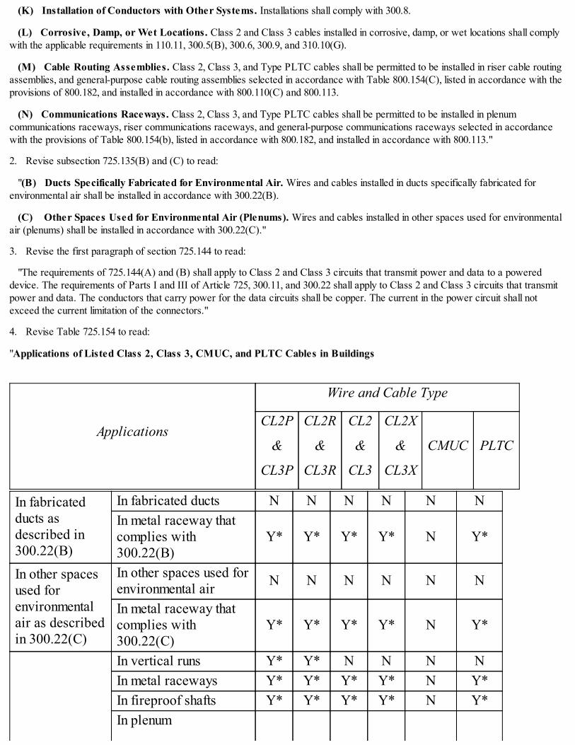
(K) Installation of Conductors with Other Systems. Installations shall comply with 300.8.
(L) Corrosive, Damp, or Wet Locations. Class 2 and Class 3 cables installed in corrosive, damp, or wet locations shall complywith the applicable requirements in 110.11, 300.5(B), 300.6, 300.9, and 310.10(G).
(M) Cable Routing Assemblies. Class 2, Class 3, and Type PLTC cables shall be permitted to be installed in riser cable routingassemblies, and general-purpose cable routing assemblies selected in accordance with Table 800.154(C), listed in accordance with theprovisions of 800.182, and installed in accordance with 800.110(C) and 800.113.
(N) Communications Raceways. Class 2, Class 3, and Type PLTC cables shall be permitted to be installed in plenumcommunications raceways, riser communications raceways, and general-purpose communications raceways selected in accordancewith the provisions of Table 800.154(b), listed in accordance with 800.182, and installed in accordance with 800.113."
2. Revise subsection 725.135(B) and (C) to read:
"(B) Ducts Specifically Fabricated for Environmental Air. Wires and cables installed in ducts specifically fabricated forenvironmental air shall be installed in accordance with 300.22(B).
(C) Other Spaces Used for Environmental Air (Plenums). Wires and cables installed in other spaces used for environmentalair (plenums) shall be installed in accordance with 300.22(C)."
3. Revise the first paragraph of section 725.144 to read:
"The requirements of 725.144(A) and (B) shall apply to Class 2 and Class 3 circuits that transmit power and data to a powereddevice. The requirements of Parts I and III of Article 725, 300.11, and 300.22 shall apply to Class 2 and Class 3 circuits that transmitpower and data. The conductors that carry power for the data circuits shall be copper. The current in the power circuit shall notexceed the current limitation of the connectors."
4. Revise Table 725.154 to read:
"Applications of Listed Class 2, Class 3, CMUC, and PLTC Cables in Buildings
Applications
Wire and Cable Type
CL2P
&
CL3P
CL2R
&
CL3R
CL2
&
CL3
CL2X
&
CL3X
CMUC PLTC
In fabricatedducts asdescribed in300.22(B)
In fabricated ducts N N N N N NIn metal raceway thatcomplies with300.22(B)
Y* Y* Y* Y* N Y*
In other spacesused forenvironmentalair as describedin 300.22(C)
In other spaces used forenvironmental air N N N N N N
In metal raceway thatcomplies with300.22(C)
Y* Y* Y* Y* N Y*
In vertical runs Y* Y* N N N NIn metal raceways Y* Y* Y* Y* N Y*In fireproof shafts Y* Y* Y* Y* N Y*In plenum
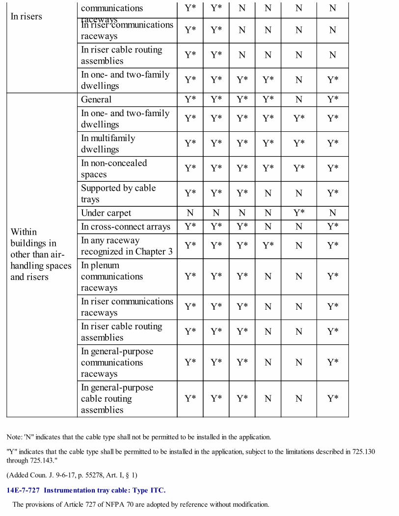
In riserscommunicationsraceways
Y* Y* N N N N
In riser communicationsraceways Y* Y* N N N N
In riser cable routingassemblies Y* Y* N N N N
In one- and two-familydwellings Y* Y* Y* Y* N Y*
Withinbuildings inother than air-handling spacesand risers
General Y* Y* Y* Y* N Y*In one- and two-familydwellings Y* Y* Y* Y* Y* Y*
In multifamilydwellings Y* Y* Y* Y* Y* Y*
In non-concealedspaces Y* Y* Y* Y* Y* Y*
Supported by cabletrays Y* Y* Y* N N Y*
Under carpet N N N N Y* NIn cross-connect arrays Y* Y* Y* N N Y*In any racewayrecognized in Chapter 3 Y* Y* Y* Y* N Y*
In plenumcommunicationsraceways
Y* Y* Y* N N Y*
In riser communicationsraceways Y* Y* Y* N N Y*
In riser cable routingassemblies Y* Y* Y* N N Y*
In general-purposecommunicationsraceways
Y* Y* Y* N N Y*
In general-purposecable routingassemblies
Y* Y* Y* N N Y*
Note: 'N" indicates that the cable type shall not be permitted to be installed in the application.
"Y" indicates that the cable type shall be permitted to be installed in the application, subject to the limitations described in 725.130through 725.143."
(Added Coun. J. 9-6-17, p. 55278, Art. I, § 1)
14E-7-727 Instrumentation tray cable: Type ITC.
The provisions of Article 727 of NFPA 70 are adopted by reference without modification.

(Added Coun. J. 9-6-17, p. 55278, Art. I, § 1)
14E-7-728 Fire-resistive cable systems.
The provisions of Article 728 of NFPA 70 are adopted by reference without modification.
(Added Coun. J. 9-6-17, p. 55278, Art. I, § 1; Amend Coun. J. 11-8-17, p. 59720, § 23)
14E-7-750 Energy management systems.
The provisions of Article 750 of NFPA 70 are adopted by reference without modification.
(Added Coun. J. 9-6-17, p. 55278, Art. I, § 1)
14E-7-760 Fire alarm systems.
The provisions of Article 760 of NFPA 70 are adopted by reference with the following modifications:
1. Revise the first paragraph of section 760.3 to read:
"Circuits and equipment shall comply with 760.3(A) through (K). Only those sections of Article 300 referenced in this article shallapply to fire alarm systems."
2. Delete both exceptions to subsection 760.3(B).
3. Delete subsections 760.3(L) and (M).
4. Revise subsections 760.53(B)(1) and (2) to read:
"(1) Ducts Specifically Fabricated for Environmental Air. Cables installed in ducts, specifically fabricated for environmentalair shall be installed in accordance 300.22(B).
(2) Other Spaces Used for Environmental Air (Plenums). Cables installed in other spaces used for environmental air shall beinstalled in accordance with 300.22(C)."
5. Revise section 760.135 to read:
"Installation of PLFA Cables in Buildings. Installation of power-limited fire alarm cables in buildings shall comply with760.135(A) through (J).
(A) Listing. PLFA cables installed in buildings shall be listed.
(B) Ducts Specifically Fabricated for Environmental Air. Wires and cables installed in ducts specifically fabricated forenvironmental air shall be installed in accordance with 300.22(B).
(C) Other Spaces Used for Environmental Air (Plenums). Cables installed in other spaces used for environmental air shall beinstalled in accordance with 300.22(C).
(D) Risers - Cables in Vertical Runs. The following cables shall be permitted in vertical runs penetrating one or more floors andin vertical runs in a shaft.
(1) Types FPLP and FPLR cables
(2) Types FPLP and FPLR cables installed in the following:
a. Plenum communications raceways
b. Riser communications raceways
c. Riser cable routing assemblies
Informational Note: See 300.21 for firestop requirements for floor penetrations.
(E) Risers - Cables in Metal Raceways. The following cables shall be permitted in metal raceways in a riser having firestops ateach floor:
(1) Types FPLP, FPLR, and FPL cables

(2) Types FPLP, FPLR, and FPL cables installed in:
a. Plenum communications raceways
b. Riser communications raceways
c. General-purpose communication raceways
Informational Note: See 300.21 for firestop requirements for floor penetrations.
(F) Risers - Cables in Fireproof Shafts. The following cables shall be permitted to be installed in fireproof riser shafts havingfirestops at each floor:
(1) Types FPLP, FPLR, and FPL cables
(2) Types FPLP, FPLR, and FPL cables installed in:
a. Plenum communications raceways
b. Riser communications raceways
c. Riser cable routing assemblies
d. General-purpose communication raceways
e. General-purpose cable routing assemblies
Informational Note: See 300.21 for firestop requirements for floor penetrations.
(G) Risers - One- and Two-Family Dwellings. The following cables shall be permitted in one- and two- family dwellings:
(1) Types FPLP, FPLR, and FPL cables
(2) Types FPLP, FPLR, and FPL cables installed in:
a. Plenum communications raceways
b. Riser communications raceways
c. Riser cable routing assemblies
d. General-purpose communication raceways
e. General-purpose cable routing assemblies
(H) Other Building Locations. The following cables shall be permitted to be installed in building locations other than the locationscovered in 770.113(B) through (H):
(1) Types FPLP, FPLR, and FPL cables
(2) Types FPLP, FPLR, and FPL cables installed in:
a. Plenum communications raceway
b. Riser communications raceway
c. Riser cable routing assemblies
d. General-purpose communication raceways
e. General-purpose cable routing assemblies
(3) Types FPLP, FPLR, and FPL cables installed in a raceway of a type allowed in Chapter 3.
(I) Nonconcealed Spaces. Cables specified in Chapter 3 and meeting the requirements of 760.179(A) and (B) shall be permittedto be installed in nonconcealed spaces where the exposed length of cable does not exceed 3 m (10 ft).
(J) Portable Fire Alarm System. A portable fire alarm system provided to protect a stage or set when not in use shall be

permitted to use wiring methods in accordance with 530.12."
6. Revise Table 760.154 to read:
"Applications of Listed PLFA Cables in Buildings
Applications
Cable Type
FPLP&
FPLP-CI
FPLR&
FPLR-CI
FPL&
FPL-CI
In fabricated ductsas described in300.22(B)
In fabricated ducts N N NIn metal raceway that complies with300.22(B) Y* Y* Y*
In other spacesused forenvironmental airas described in300.22(C)
In other spaces used forenvironmental air N N N
In metal raceway that complies with300.22(C) Y* Y* Y*
In risers
In vertical runs Y* Y* NIn metal raceways Y* Y* Y*In fireproof shafts Y* Y* Y*In plenum communications raceways Y* Y* NIn riser communications raceways Y* Y* NIn riser cable routing assemblies Y* Y* NIn one- and two-family dwellings Y* Y* Y*
Within buildings inother than air-handling spacesand risers
General Y* Y* Y*Supported by cable trays Y* Y* Y*In any raceway recognized inChapter 3 Y* Y* Y*
In plenum communications raceways Y* Y* Y*In riser communications raceways Y* Y* Y*In riser cable routing assemblies Y* Y* Y*In general-purpose communicationsraceways Y* Y* Y*
In general-purpose cable routingassemblies Y* Y* Y*
Note: An "N" indicates that the cable type is not permitted to be installed in the application. A "Y*" indicates that the cable is permittedto be installed in the application, subject to the limitations described in 770.110 and 770.113."

7. Insert new parts V and VI to read:
"Part V. Required Fire Alarm and Emergency Voice Communications Systems
760.180General. The provisions of the Chicago Building Code governing the installation of required fire alarm systems andrequired emergency voice communication systems are hereby declared retrospective as well as prospective and shall apply to bothexisting buildings and buildings hereafter constructed, altered or converted.
Fire alarm systems and/or emergency voice communication systems are required by the
Chicago Building Code for occupancies including but not limited to: schools, hospitals, day care centers, nursing homes, hotels andhigh rise buildings.
Informational Note: See Chapters 13-196 and 15-16 of the Chicago Building Code for requirements related to fire alarm systems andvoice communication systems.
The workmanship, equipment and quality of installation shall conform to the requirements of Chapter 1 and Chapter 3 of this Code.The installation shall not be deemed complete before notification and inspection by the authority having jurisdiction.
760.181Plans Required. Before work is begun on the installation or alteration of a required fire alarm or emergency voicecommunication system, complete and detailed plans and specifications of the proposed installation shall be submitted to the authorityhaving jurisdiction. Only after approval by the authority having jurisdiction may work begin.
In addition to any other information required by the authority having jurisdiction, the plans shall include:
a. Complete legible raceway diagrams showing all horizontal and lateral sections and two corresponding legible circuit diagrams
b. Locations and details of the circuits of the control panel, alarm sending stations, automatic detectors, alarm sounding devices,supervisory test switches, trouble sounding device, trouble sounding device test switch, pilot light and switch
c. Details of separate conductors in each raceway and the connections to their respective terminals
d. One-line wiring diagrams showing the service entrance conductors, equipment, and fire alarm supply source
e. Full load calculations for all initiating and signaling circuits
All diagrams shall be identified with the complete name, address, and class of occupancy such as school, hotel, hospital, etc.
760.182Wiring Methods. The installation shall be performed such that the equipment, quality and workmanship conform to therequirements of Chapters 1 and 3 of this Code and as provided for in 760.182(A) through (G).
(A) Raceway. All conductors of the system shall be enclosed in an approved metal raceway system. This raceway system shall bededicated and contain only the system conductors and any required interfaces.
Exception No. 1: Elevator traveling cables.
Exception No. 2: Type MI cable need not be installed in raceway.
(B) Raceway Fill. The fill of any part of the raceway shall not exceed 40% of the internal cross- sectional area of the raceway.
(C) Enclosures Fill. The fill of enclosures shall be as found in 314.16. Equipment protruding into the box or enclosure reduces thevolume of the enclosure accordingly and shall be considered for fill purposes.
Exception: Listed system control equipment enclosures where all entering conductors terminate to the equipment within theenclosure.
(D) Marking. The box covers and all raceways for fire alarm systems shall be red in color.
(E) Protection. The raceway system shall be protected to minimize physical damage.
Where other sections of the Chicago Building Code require protection from fire, the raceway system shall follow one of themethods below:
(1) Run within a room or area(s) dedicated to the protection of electrical equipment, meeting the fire resistance constructionrating of the specifying section of the Chicago Building Code.

(2) Protected by an electrical circuit protective system listed to meet UL 1724. The installation shall comply with any restrictionsprovided in the listing.
(3) Embedded in concrete with a minimum of 50 mm (2 in.) cover around the raceway. Any supports for the concrete shall beprotected by equivalent encasement or other means to achieve the required fire resistance rating.
(F) System Control Equipment. Listed enclosures and back-boxes containing system control equipment shall not have anyconductors entering other than those conductors that terminate at the control equipment within these enclosures.
(G) Foreign Equipment Interfaces. Where equipment is installed to interface with outside equipment, foreign to the alarmsystem, and a monitoring relay is used for this purpose, the enclosure containing the monitoring relay shall be within 914 mm (3 ft) fromthe equipment being served.
Informational Note: An example of this equipment would be fan, electric lock or disconnect status monitoring.
(H) Voice Communication Circuits. The voice communication circuits and the fire detection circuits of a required fire alarmsystem may share the same conduit or approved raceway and use common control equipment and power supplies, subject to760.182(B) and any fire protection requirement applicable to the voice communication risers.
Informational Note: See Section 13-76-080 for additional requirements applicable to high rise electrical systems.
760.183Fire Alarm and Emergency Voice Communication Circuit Conductors. Conductors shall have the properties ofNPLFA circuit conductors as covered in Part II of Article 760. The minimum size shall be 16 AWG. 18 AWG shall be permitted wheninstalled as part of a multi-conductor cable.
Exception No. 1: Conductors which are listed and approved for the inter-connection of component parts for control equipment withina common enclosure or between close-nippled (6 in. or less) enclosures.
Exception No. 2: Conductors for coaxial cables, a minimum of 22 AWG for the center conductor.
Exception No. 3: Non-conductive fiber optic conductors.
Exception No. 4: Listed insulated continuous line- type heat detectors.
Exception No. 5: Listed elevator traveling cables.
Where equipment is listed to use a conductor size larger than the above minimums, the listed
minimum shall be followed. All conductors making up a complete circuit shall be of the same size throughout that circuit.
All conductors and cables shall be installed in a manner consistent with their listing, following all specifications by the manufacturerrelated and requisite for such listing.
(A) Ampacity. 18 AWG and 16 AWG conductors shall only supply loads that do not exceed the ampacities given in Table 402.5.14 AWG and larger conductors shall only supply loads that do not exceed the ampacities given in 310.15 as applicable.
(B) Voltage Drop. The maximum voltage drop at any point along an individual circuit shall not exceed 5% of the nominal voltageinitially provided. The calculation for voltage drop shall be made at the minimum operating voltage supplied by the control equipmentwhen operating on secondary power using the maximum possible current draw for that circuit.
(C) Electrical Circuit Protection. To prevent possible system performance degradation or destruction due to electrical,electromagnetic, radio frequency, surge, transient or induction of or into any part of the system the following shall be performed:
(1) Branch circuits feeding system power supplies shall be maintained a minimum of 50 mm (2 in.) from all other conductorswithin an enclosure.
(2) Branch circuits feeding system power supplies shall be provided with listed transient voltage surge suppressors with a let-through voltage rating not greater than 400 volts.
(3) AC circuits receiving power from system power supplies shall use twisted pair conductors, shielded conductors or both asnecessary.
(4) Any conductive circuit which runs outside the building envelope, shall be protected with listed isolated loop circuit protectors.The protectors shall be mounted within 1.52 m (5 ft) of the penetration to the outside with no equipment connected to the circuitbetween the protector and the penetration to the outside. The protector shall be suitably grounded.

(5) Any circuit for which the system is listed as using a twisted pair, shield or both shall provide these conductors in accordancewith the manufacturer's instructions.
(D) Terminations. All conductors shall be securely connected to their respective terminations by one of the following means:
(1) Wrapping a single solid or bunch-tinned conductor 7/8 turn around a screw terminal.
(2) Placing a single conductor under a cup washer at a screw terminal.
(3) Under a notched clamping plate for the termination of two separate solid or bunch-tinned conductors of the same gauge size.
(4) Inside a pressure terminal where pressure is provided by a set screw to a single conductor.
Exception No. 1: Conductors which are part of an assembly provided by the manufacturer with retained plug connectors usedwithin an enclosure or close-nippled (6 in.) enclosures.
Exception No. 2: Non-conductive fiber optic conductors.
(E) Splices. All conductors shall be installed continuous from the control equipment to all field equipment terminations without anysplices, taps or intermediate terminations until reaching the end of the circuit.
Exception No. 1: Connections to elevator traveling cables using a suitable listed fully insulated terminal block meeting thetermination requirements of 760.183(D).
Exception No. 2: AC/DC circuits receiving power from system power supplies and supplying system equipment on multiplefloors/zones shall use a suitable listed fully insulated power distribution block meeting the termination requirements of 760.183(D).
Exception No. 3: Where shielded conductors are connected to equipment which has no provision for shield drain wire termination asuitable listed fully insulated terminal block meeting the termination requirements of 760.183(D).
Exception No. 4: Connection to listed supervisory devices manufactured with built-in monitoring switches having conductor leadsshall use a suitable listed fully insulated terminal block meeting the termination requirements of 760.183(D).
Exception No. 5: End-of-line devices which do not have separate terminals on equipment on which to terminate shall use a suitablelisted fully insulated terminal block meeting the termination requirements of 760.183(D).
Exception No. 6: For existing systems with in place conductors where the system will be extended or altered, a suitable listed fullyinsulated terminal block meeting the termination requirements of 760.183(D) shall be used when:
(1) Special permission has been granted
(2) There is no T-tapping or other wiring method that will impair the required supervision
(3) Drawings show the exact location of each junction box containing a splice
(4) Junction box containing such splices shall be located in a protected fire rated area as required in 760.182(E)
(5) Only one such box shall be permitted on a floor and shall be painted red and marked "FIRE ALARM SPLICE."
760.184Power Supply. The primary power supply to a required fire alarm system shall originate from an emergency systeminstalled as required in Article 700.
Emergency branch circuits supplying the fire alarm system shall be grouped and permanently identified as "FIRE ALARMCIRCUIT."
Informational Note: Refer to NFPA 72, Fire Alarm and Signaling Code, See 10.6.5.2.2 Circuit Identification and Accessibilityregarding more labeling of fire alarm disconnecting means.
The secondary power supply capacity for a required fire alarm system shall not be less than as specified by the authority havingjurisdiction for the type of occupancy served.
760.185Location. The control equipment shall be located as near to the source of supply as is practicable. The control equipmentshall be located within a room, dedicated to the protection of electrical equipment, of one-hour fire rated construction with one-hourrated and labeled doors and one-hour protected openings other than doors. No control equipment shall be located below grade.

760.187Approval. The required fire alarm system and all equipment used in conjunction with the fire alarm system shall be of atype approved by authority having jurisdiction.
Part VI. Connection of a Required Fire Alarm System and Emergency Voice Communication System to an Off-PremiseMonitoring System
760.208General. Where the Chicago Building Code requires that a required fire alarm system or emergency voice communicationsystem be connected to an off-premise monitoring service, the provisions of this Part and Part VII shall apply. Such connection shallbe considered as a component of the required fire alarm system or emergency voice communication system and shall be incorporatedin the plans and diagrams which are required by 760.181.
760.209 Type of Service. The off-premise monitoring service shall consist of either a municipal fire alarm box or a central stationservice. The type of service shall be as determined by the authority having jurisdiction.
760.210 Wiring Method.
(A) Municipal Fire Alarm Box. The conductors connecting the required fire alarm system to the municipal fire alarm box shallbe run in metal conduit. Where the conductors run outside the building they shall be encased in galvanized rigid metal conduit orintermediate metal conduit from the penetration of the building envelope to the pedestal of the municipal fire alarm box. The conduitshall contain no conductors other than those necessary for operation of the municipal fire alarm box and conform to the following:
(1) The minimum size conduit used shall be 2 in. When outside it shall be buried a minimum of 24 in. below surrounding grade.The conduit shall be continuous with no junction boxes from the control equipment to municipal fire alarm box shell.
(2) Five 14 AWG or larger conductors shall be run. Each shall be of a different color. One shall be green, which shall be bondedto the enclosure of the control equipment inside the building and to the shell of the municipal box. Two of the remaining conductorsshall be used for the fire alarm trip coil circuit. The two unused conductors will be spares.
(3) All conductors run outside the building shall be protected by a listed isolated loop circuit protector. The protector shall belocated in a junction box at the point of exit from the building.
(B) Central Station Service. The conductors connecting the required fire alarm system or emergency voice communicationsystem to the central station service shall be run in metal conduit. The conduit shall contain no conductors other than those necessaryfor operation of the central station service and shall conform to the following:
(1) The minimum size conduit shall be 1 in. and the conduit shall be continuous with no junction boxes from the control equipmentto the central station service equipment.
(2) Where required by 760.182, conductors between the control equipment monitored and the central station service equipmentshall be protected for a minimum of one hour by a listed electrical circuit protective system. The installation shall comply with anyrestrictions provided in the listing.
(3) Sufficient conductors shall be run to monitor all functions as required by the authority having jurisdiction. All conductors shallbe color coded. One provided conductor shall be green, which shall be bonded to the enclosure of the control equipment monitored andto the enclosure of the Central Station Service equipment. Two provided conductors shall be provided as spare conductors.
(4) All current carrying conductors run outside the building to the central station monitoring facility shall be protected by a listedsecondary protector for communications circuits. The protector shall be located in a junction box at the point of exit from the building.
760.211Power Supply. Any equipment requiring power for transmission of signals off premise shall obtain this power as specifiedin 760.184 from a separate circuit. Any equipment within the building which is required for the completion of transmission off- premiseshall also meet these requirements. (i.e. fiber- optic network interface power supply).
760.212Function of the Connection. This connection is required so that any fire alarm, and supervisory or trouble condition asrequired, inside of the building will automatically notify the off-premise monitoring service of said fire or condition. All supervisory andtrouble conditions shall be annunciated in a manned location as directed by the Chicago Fire Department.
760.213Supervision. The circuits necessary for these connections shall be electrically supervised for energy failure, open circuitfault, and ground fault.
Exception: Public utility communication circuits alter the interface to the transmission equipment need only be monitored forconditions which would prevent transmission.

760.214Fire Drill Disconnect Switch. An approved type of switch may be provided which will disconnect the required fire alarmsystem from the municipal fire alarm box. This switch shall be mounted in the front of the control panel and shall be externallyoperable. It shall be of the key operated lock type or be a passcode protected keypad type. The disconnection shall cause a troublecondition in the system. The key shall be captive when the disconnect is in the "on" position. The passcode protected keypad shall notrequire any passcode or special knowledge to reactivate. The central station service equipment shall have no provision for adrill/disconnect feature.
760.215Notification of Discontinuation of Service. Where a central station service discontinues service to a building, the centralstation service shall notify the Chicago Fire Department within 24 hours."
(Added Coun. J. 9-6-17, p. 55278, Art. I, § 1)
14E-7-770 Optical fiber cables and raceways.
The provisions of Article 770 of NFPA 70 are adopted by reference with the following modifications:
1. Revise section 770.110 to read:
"Raceways and Cable Routing Assemblies for Optical Fiber Cables.
(A) Types of Raceways. Optical fiber cables shall be permitted to be installed in any raceway that complies with either770.110(A)(1) or (A)(2) and in cable routing assemblies installed in compliance with 770.110(C).
(1) Raceways Recognized in Chapter 3. Optical fiber cables shall be permitted to be installed in any raceway included inChapter 3. The raceways shall be installed in accordance with the requirements of Chapter 3.
(2) Communications Raceways. Optical fiber cables shall be permitted to be installed in listed plenum communicationsraceway, listed riser communications raceways, and listed general-purpose optical fiber raceway selected in accordance with theprovisions of 770.113, 800.110 and 800.113.
(B) Raceway Fill for Optical Fiber Cables. Raceway fill for optical fibers cables shall comply with either 770.110(B)(1) or (B)(2).
(1) Without Electric Light or Power Conductors. Where optical fiber cables are installed in raceway without electric light orpower conductors, the raceway fill requirements of Chapters 3 and 9 shall not apply.
(2) Nonconductive Optical Fiber Cables with Electric Light or Power Conductors. Where nonconductive optical fibercables are installed with electric light or power conductors in a raceway, the raceway fill requirements of Chapters 3 and 9 shall apply.
(C) Cable Routing Assemblies. Optical fiber cables shall be permitted to be installed in riser cable routing assemblies, andgeneral-purpose cable routing assemblies selected in accordance with the provisions of 800.113 and Table 880.154(c), listed inaccordance with 800.182, and installed in accordance with 770.110(C)(1) and (C)(2).
(1) Horizontal Support. Cable routing assemblies shall be supported where run horizontally at intervals not to exceed 900 mm(3 ft), and at each end or joint, unless listed for other support intervals. In no case shall the distance between supports exceed 3 m (10ft).
(2) Vertical Support. Vertical runs of cable routing assemblies shall be supported at intervals not exceeding 1.2 m (4 ft), unlesslisted for other support intervals, and shall not have more than one joint between supports."
2. Revisesection 770.113 to read:
"Installation of Optical Fiber Cables. Installation of optical fiber cables shall also comply with 770.13(A) through (J). Installationof raceways shall comply with 770.110.
(A) Listing. Optical fiber cables installed in buildings shall be listed in accordance with 770.110.
Exception: Optical fiber cables that comply with 770.48 shall not be required to be listed.
(B) Ducts Specifically Fabricated for Environmental Air. Wires and cables installed in ducts specifically fabricated forenvironmental air shall be installed in accordance with 300.22(B).
(C) Other Spaces Used for Environmental Air (Plenums). Wires and cables installed in other spaces used for environmentalair (plenums) shall be installed in accordance with 300.22(C).

(D) Risers - Cables in Vertical Runs. The following cables shall be permitted in vertical runs penetrating one or more floors andin vertical runs in a shaft:
(1) Types OFNP, OFCP, OFNR, and OFCR cables
(2) Types OFNP, OFCP, OFNR, and cables installed in:
a. Plenum communications raceway
b. Riser communications raceway
c. Riser cable routing assemblies
(E) Risers - Cables in Metal Raceways. The following cables shall be permitted in metal raceways in a riser having firestops ateach floor:
(1) Types OFNP, OFCP, OFNR, OFCR, OFNG, OFCG, OFN, and OFC cables
(2) Types OFNP, OFCP, OFNR, OFCR, OFNG, OFCG, OFN, and OFC cables installed in:
a. Plenum communications raceway
b. Riser communications raceway
c. General-purpose communication raceways
Informational Note: See 770.26 for firestop requirements for floor penetrations.
(F) Risers - Cables in Fireproof Shafts. The following cables shall be permitted to be installed in fireproof riser shafts havingfirestops at each floor:
(1) Types OFNP, OFCP, OFNR, OFCR, OFNG, OFCG, OFN, and OFC cables
(2) Types OFNP, OFCP, OFNR, OFCR, OFNG, OFCG, OFN, and OFC cables installed in:
a. Plenum communications raceway
b. Riser communications raceway
c. Riser cable routing assemblies
d. General-purpose communication raceways
e. General-purpose cable routing assemblies
Informational Note: See 770.26 for firestop requirements for floor penetrations.
(G) Risers - One- and Two-Family Dwellings. The following cables shall be permitted in one- and two- family dwellings:
(1) Types OFNP, OFCP, OFNR, OFCR, OFNG, OFCG, OFN, and OFC cables
(2) Types OFNP, OFCP, OFNR, OFCR, OFNG, OFCG, OFN, and OFC cables installed in:
a. Plenum communications raceway
b. Riser communications raceway
c. Riser cable routing assemblies
d. General-purpose communication raceways
e. General-purpose cable routing assemblies
(H) Cable Trays. The following cables shall be permitted to be supported by cable trays:
(1) Types OFNP, OFCP, OFNR, OFCR, OFNG, OFCG, OFN, and OFC cables
(2) Types OFNP, OFCP, OFNR, OFCR, OFNG, OFCG, OFN, and OFC cables installed in:
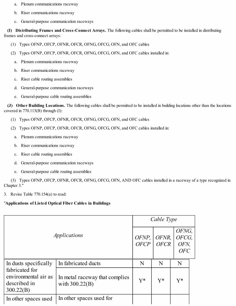
a. Plenum communications raceway
b. Riser communications raceway
c. General-purpose communication raceways
(I) Distributing Frames and Cross-Connect Arrays. The following cables shall be permitted to be installed in distributingframes and cross-connect arrays:
(1) Types OFNP, OFCP, OFNR, OFCR, OFNG, OFCG, OFN, and OFC cables
(2) Types OFNP, OFCP, OFNR, OFCR, OFNG, OFCG, OFN, and OFC cables installed in:
a. Plenum communications raceway
b. Riser communications raceway
c. Riser cable routing assemblies
d. General-purpose communication raceways
e. General-purpose cable routing assemblies
(J) Other Building Locations. The following cables shall be permitted to be installed in building locations other than the locationscovered in 770.113(B) through (I):
(1) Types OFNP, OFCP, OFNR, OFCR, OFNG, OFCG, OFN, and OFC cables
(2) Types OFNP, OFCP, OFNR, OFCR, OFNG, OFCG, OFN, and OFC cables installed in:
a. Plenum communications raceway
b. Riser communications raceway
c. Riser cable routing assemblies
d. General-purpose communication raceways
e. General-purpose cable routing assemblies
(3) Types OFNP, OFCP, OFNR, OFCR, OFNG, OFCG, OFN, AND OFC cables installed in a raceway of a type recognized inChapter 3."
3. Revise Table 770.154(a) to read:
"Applications of Listed Optical Fiber Cables in Buildings
Applications
Cable Type
OFNP,OFCP
OFNR,OFCR
OFNG,OFCG,OFN,OFC
In dusts specificallyfabricated forenvironmental air asdescribed in300.22(B)
In fabricated ducts N N N
In metal raceway that complieswith 300.22(B) Y* Y* Y*
In other spaces used In other spaces used for
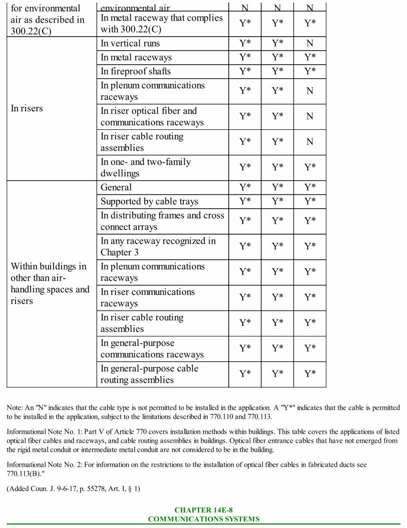
for environmentalair as described in300.22(C)
environmental air N N NIn metal raceway that complieswith 300.22(C) Y* Y* Y*
In risers
In vertical runs Y* Y* NIn metal raceways Y* Y* Y*In fireproof shafts Y* Y* Y*In plenum communicationsraceways Y* Y* N
In riser optical fiber andcommunications raceways Y* Y* N
In riser cable routingassemblies Y* Y* N
In one- and two-familydwellings Y* Y* Y*
Within buildings inother than air-handling spaces andrisers
General Y* Y* Y*Supported by cable trays Y* Y* Y*In distributing frames and crossconnect arrays Y* Y* Y*
In any raceway recognized inChapter 3 Y* Y* Y*
In plenum communicationsraceways Y* Y* Y*
In riser communicationsraceways Y* Y* Y*
In riser cable routingassemblies Y* Y* Y*
In general-purposecommunications raceways Y* Y* Y*
In general-purpose cablerouting assemblies Y* Y* Y*
Note: An "N" indicates that the cable type is not permitted to be installed in the application. A "Y*" indicates that the cable is permittedto be installed in the application, subject to the limitations described in 770.110 and 770.113.
Informational Note No. 1: Part V of Article 770 covers installation methods within buildings. This table covers the applications of listedoptical fiber cables and raceways, and cable routing assemblies in buildings. Optical fiber entrance cables that have not emerged fromthe rigid metal conduit or intermediate metal conduit are not considered to be in the building.
Informational Note No. 2: For information on the restrictions to the installation of optical fiber cables in fabricated ducts see770.113(B)."
(Added Coun. J. 9-6-17, p. 55278, Art. I, § 1)
CHAPTER 14E-8COMMUNICATIONS SYSTEMS
14E-8-800 Communications circuits.
14E-8-810 Radio and television equipment.
14E-8-820 Community antenna television and radio distribution systems.
14E-8-830 Network-powered broadband communications systems.
14E-8-840 Premises-powered broadband communications systems.
14E-8-800 Communications circuits.
The provisions of Article 800 of NFPA 70 are adopted by reference with the following modifications:
1. Revise subsection 800.110(A)(2) to read:
"Communications Raceways. Communications wires and cables shall be permitted to be installed in plenum communicationsraceways, riser communications raceways, and general-purpose communications raceways selected in accordance with Table800.154(b), listed in accordance with 800.182, and installed in accordance with 800.113."
2. Revise subsections 800.113(B) through (L) to read:
"(B) Ducts Specifically Fabricated for Environmental Air. Wires and cables installed in ducts specifically fabricated forenvironmental air shall be installed in accordance with 300.22(B).
(C) Other Spaces Used for Environmental Air (Plenums). Wires and cables installed in other spaces used for environmentalair (plenums) shall be installed in accordance with 300.22(C).
(D) Risers - Cables, Raceways, and Cable Routing Assemblies in Vertical Runs. The following cables, raceways, andcable routing assemblies shall be permitted in vertical runs penetrating one or more floors and in vertical runs in a shaft:
(1) Types CMP and CMR cables
(2) Plenum and riser communications raceways
(3) Riser cable routing assemblies
(4) Types CMP and CMR cables installed in:
a. Plenum communications raceways
b. Riser communications raceways
c. Riser cable routing assemblies
Informational Note: See 800.26 for firestop requirements for floor penetrations.
(E) Risers - Cables and Innerducts in Metal Raceways. The following cables and innerducts shall be permitted in metalraceways in a riser having firestops at each floor:
(1) Types CMP, CMR, CMG, CM, and CMX cables
(2) Plenum, riser, and general-purpose communications raceways
(3) Types CMP, CMR, CMG, CM, and CMX cables installed in:
a. Plenum communications raceways (innerduct)
b. Riser communications raceways (innerduct)
c. General-purpose communications raceways (innerduct)
Informational Note: See 800.26 for firestop requirements for floor penetrations.
(F) Risers - Cables, Raceways, and Cable Routing Assemblies in Fireproof Shafts. The following cables, raceways, andcable routing assemblies shall be permitted to be installed in fire-proof riser shafts having firestops at each floor:

(1) Types CMP, CMR, CMG, CM, and CMX cables
(2) Plenum, riser, and general-purpose communications raceways
(3) Riser, and general-purpose cable routing assemblies
(4) Types CMP, CMR, CMG, and CM cables installed in:
a. Plenum, riser, and general-purpose communications raceways
b. Riser, and general-purpose cable routing assemblies
Informational Note: See 800.26 for firestop requirements for floor penetrations.
(G) Risers - One- and Two-Family Dwellings. The following cables, raceways, and cable routing assemblies shall be permittedin one- and two-family dwellings:
(1) Types CMP, CMR, CMG, and CM cables
(2) Type CMX cables less than 0.25 in. in diameter
(3) Plenum, riser, and general-purpose communications raceways
(4) Riser, and general-purpose cable routing assemblies
(5) Types CMP, CMR, CMG, and CM cables installed in:
a. Plenum, riser, and general-purpose communications raceways
b. Riser, and general-purpose cable routing assemblies
(H) Cable Trays. The following wires, cables, and raceways shall be permitted to be supported by cable trays:
(1) Types CMP, CMR, CMG, and CM cables
(2) Plenum, riser, and general-purpose communications raceways
(3) Communications wires and Types CMP, CR, CMG, and CM cables installed in:
a. Plenum communications raceways
b. Riser communications raceways
c. General-purpose communications raceways
(I) Distributing Frames and Cross-Connect Arrays. The following wires, cables, raceways, and cable routing assemblies shallbe permitted to be installed in distributing frames and cross-connect arrays:
(1) Types CMP, CMR, CMG, and CM cables and communications wires
(2) Plenum, riser, and general-purpose communications raceways
(3) Riser, and general-purpose cable routing assemblies
(4) Communications wires and Types CMP, CMR, CMG, and CM cables installed in:
a. Plenum communications raceways
b. Riser communications raceways
c. General-purpose communications raceways
d. Riser cable routing assemblies
e. General-purpose cable routing assemblies
(J) Other Building Locations. The following wires, cables, raceways, and cable routing assemblies shall be permitted to beinstalled in building locations other than the locations covered in 800.113(B) through (I):
(1) Types CMP, CMR, CMG, and CM cables
(2) A maximum of 3 m (10 ft) of exposed Type CMX in non-concealed spaces
(3) Plenum, riser, and general-purpose communications raceways
(4) Riser, and general-purpose cable routing assemblies
(5) Communications wires and Types CMP, CMR, CMG, and CM cables installed in:
a. Plenum communications raceways
b. Riser communications raceways
c. General-purpose communications raceways
(6) Types CMP, CMR, CMG, and CM cables installed in:
a. Riser cable routing assemblies
b. General-purpose cable routing assemblies
(7) Communications wires and Types CMP, CMR, CMG, CM, and CMX cables installed in raceways recognized in Chapter 3
(8) Type CMUC under-carpet communications wires and cables installed under carpet, modular tiles, and planks
(K) Multifamily Dwellings. The following cables, raceways, and cable routing assemblies shall be permitted to be installed inmultifamily dwellings in locations other than the locations covered in 800.113(B) through (G):
(1) Types CMP, CMR, CMG, and CM cables
(2) Type CMX cables less than 0.25 in. in diameter in nonconcealed spaces
(3) Plenum, riser, and general-purpose communications raceways
(4) Riser, and general-purpose cable routing assemblies
(5) Communications wires and Types CMP, CMR, CMG, and CM cables installed in:
a. Plenum communications raceways
b. Riser communications raceways
c. General-purpose communications raceways
(6) Types CMP, CMR, CMG, and CM cables installed in:
a. Riser cable routing assemblies
b. General-purpose cable routing assemblies
(7) Communications wires and Types CMP, CMR, CMG, CM, and CMX cables installed in raceways recognized in Chapter 3
(8) Type CMUC under-carpet communications wires and cables installed under carpet, modular tiles, and planks
(L) One- and Two-Family Dwellings. The following cables, raceways, and cable routing assemblies shall be permitted to beinstalled in one- and two-family dwellings in locations other than the locations covered in 800.113(B) through 800.113(F):
(1) Types CMP, CMR, CMG, and CM cables
(2) Type CMX cables less than 6 mm (0.25 in.) in diameter
(3) Plenum, riser, and general-purpose communications raceways
(4) Riser, and general-purpose cable routing assemblies
(5) Communications wires and Types CMP, CMR, CMG, and CM cables installed in:

a. Plenum communications raceways
b. Riser communications raceways
c. General-purpose communications raceways
(6) Types CMP, CMR, CMG, and CM cables installed in:
a. Riser cable routing assemblies
b. General-purpose cable routing assemblies
(7) Communications wires and Types CMP, CMR, CMG, CM, and CMX cables installed in raceways recognized in Chapter 3
(8) Type CMUC under-carpet communications wires and cables installed under carpet, modular tiles, and planks
(9) Hybrid power and communications cable listed in accordance with 800.179(I)"
3. Revise Table 800.154(a) to read:
"Applications of Listed Communications Wires and Cables in Buildings
Applications
Wire and Cable Type
CMP CMR CMGCM CMX CMU
C
Hybrid power&
CommunicationCables
CommunicationsWires
In ductsspecificallyfabricated forenvironmentalair as describedin 300.22(B)
In fabricated ducts N N N N N N N
In metal racewaythat complies with300.22(B)
Y* Y* Y* Y N N N
In other spacesused forenvironmentalair as describedin 300.22(C)
In other spaces usedfor environmentalair as described in300.22(C)
N N N N N N N
In metal racewaythat complies with300.22(C)
Y* Y* Y* Y* N N Y*
In risers
In vertical runs Y* Y* N N N N NIn metal raceways Y* Y* Y* Y N N NIn fireproof shafts Y* Y* Y* Y N N NIn plenumcommunicationsraceways
Y* Y* N N N N N
In risercommunications Y* Y* N N N N N
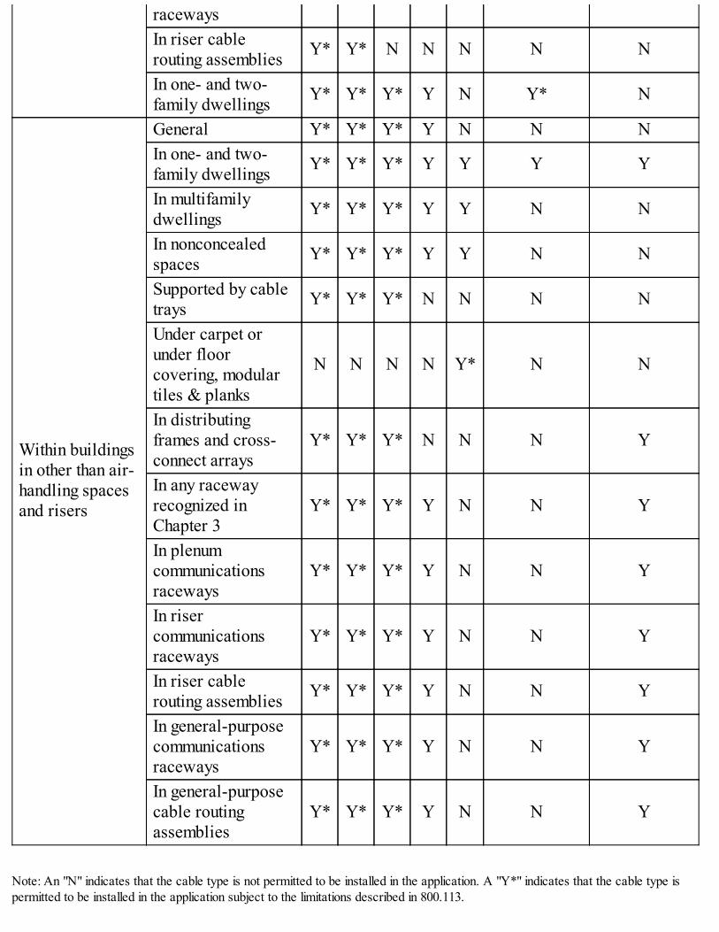
racewaysIn riser cablerouting assemblies Y* Y* N N N N N
In one- and two-family dwellings Y* Y* Y* Y N Y* N
Within buildingsin other than air-handling spacesand risers
General Y* Y* Y* Y N N NIn one- and two-family dwellings Y* Y* Y* Y Y Y Y
In multifamilydwellings Y* Y* Y* Y Y N N
In nonconcealedspaces Y* Y* Y* Y Y N N
Supported by cabletrays Y* Y* Y* N N N N
Under carpet orunder floorcovering, modulartiles & planks
N N N N Y* N N
In distributingframes and cross-connect arrays
Y* Y* Y* N N N Y
In any racewayrecognized inChapter 3
Y* Y* Y* Y N N Y
In plenumcommunicationsraceways
Y* Y* Y* Y N N Y
In risercommunicationsraceways
Y* Y* Y* Y N N Y
In riser cablerouting assemblies Y* Y* Y* Y N N Y
In general-purposecommunicationsraceways
Y* Y* Y* Y N N Y
In general-purposecable routingassemblies
Y* Y* Y* Y N N Y
Note: An "N" indicates that the cable type is not permitted to be installed in the application. A "Y*" indicates that the cable type ispermitted to be installed in the application subject to the limitations described in 800.113.

Informational Note No. 1: Part V of Article 800 covers installation methods within buildings. This table covers the applications of listedcommunications wires, cables, and raceways in buildings.
Informational Note No. 2: For information on the restrictions to the installation of communications cables in fabricated ducts, see800.113(B)"
4. Revise Table 800.154(b) to read:
"Applications of Listed Communications Raceways in Buildings
Applications
Listed CommunicationsRaceway Type
Plenum Riser General-Purpose
In ducts specificallyfabricated forenvironmental air asdescribed in300.22(B)
In fabricated ducts N N N
In metal raceway thatcomplies with 300.22(B) N N N
In other spaces usedfor environmental air(plenums) asdescribed in300.22(C)
In other spaces used forenvironmental air asdescribed in 300.22(C)
N N N
In metal raceway thatcomplies with 300.22(C) Y* Y* Y*
In risers
In vertical runs Y* Y* Y*In metal raceways Y* Y* Y*In fireproof shafts Y* Y* Y*In riser cable routingassemblies N N N
In one- and two-familydwellings Y* Y* Y*
Within buildings inother than air-handling spaces andrisers
General Y* Y* Y*In one- and two-familydwellings Y* Y* Y*
In multifamily dwellings Y* Y* Y*In nonconcealed spaces Y* Y* Y*Supported by cable trays Y* Y* Y*Under carpet or under floorcovering, modular tiles &planks
N N N
In distributing frames andcross-connect arrays Y* Y* Y*

In any raceway recognizedin Chapter 3
Y* Y* Y*
In riser cable routingassemblies N N N
In general-purpose cablerouting assemblies N N N
Note: An "N" indicates that the communications raceway type shall not be permitted to be installed in the application. A "Y*" indicatesthat the communications raceway type shall be permitted to be installed in the application, subject to the limitations described in800.110 and 800.113"
5. Revise Table 800.154(c) to read:
"Applications of Listed Cable Routing Assemblies in Buildings
Applications
ListedCommunications
Raceway Type
Riser General-Purpose
In ducts specificallyfabricated forenvironmental air asdescribed in300.22(B)
In fabricated ducts N N
In metal raceway that complieswith 300.22(B) N N
In other spaces usedfor environmental airas described in300.22(C)
In other spaces used forenvironmental air as described in300.22(C)
N N
In metal raceway that complieswith 300.22(C) Y* Y*
In risers
In vertical runs Y* Y*In metal raceways Y* Y*In fireproof shafts Y* Y*In riser cable routing assemblies N NIn one- and two-family dwellings Y* Y*
Within buildings inother than air-
General Y* Y*In one- and two-family dwellings Y* Y*In multifamily dwellings Y* Y*In nonconcealed spaces Y* Y*Supported by cable trays Y* Y*Under carpet or under floorcovering, modular tiles & planks N N

handling spaces andrisers
In distributing frames and cross-connect arrays Y* Y*
In any raceway recognized inChapter 3 Y* Y*
In riser cable routing assemblies N NIn general-purpose cable routingassemblies N N
Note: An "N" indicates that the cable routing assembly type shall not be permitted to be installed in the application. A "Y*" indicatesthat the cable routing assembly type shall be permitted to be installed in the application, subject to the limitations described in 800.110and 800.113"
6. Revise the first paragraph of Section 800.179 to read:
"Communications wires and cables shall be listed in accordance with 800.179(A) through (H) and marked in accordance with Table800.179. Conductors in communications cables, other than in a coaxial cable, shall be copper."
7. Delete subsection 800.179(I) and the subsequent informational note.
8. Revise subsection 800.182(A) to read:
"Plenum Communications Raceways. Plenum communications raceways shall be listed as having adequate fire-resistant and low-smoke-producing characteristics."
9. Revise Table 800.182(A) to read:
"Cable Routing Assembly Markings
Type MarkingRiser Cable RoutingAssembly
Riser Cable RoutingAssembly
General-Purpose CableRouting Assembly
General-Purpose RoutingAssembly
10. Delete Informational Note No. 3 in subsection 800.182(A).
(Added Coun. J. 9-6-17, p. 55278, Art. I, § 1)
14E-8-810 Radio and television equipment.
The provisions of Article 810 of NFPA 70 are adopted by reference without modification.
(Added Coun. J. 9-6-17, p. 55278, Art. I, § 1)
14E-8-820 Community antenna television and radio distribution systems.
The provisions of Article 820 of NFPA 70 are adopted by reference with the following modifications:
1. Revise the first paragraph of section 820.24 to read:
"Community television and radio distribution systems shall be installed in a neat and workmanlike manner. Coaxial cables installedexposed on the surface of ceiling and sidewalls shall be supported by the building structure in such a manner that the cables will not bedamaged by normal building use. Such cables shall be secured by hardware including straps, staples, cable ties, hangers, or similarfittings designed and installed so as not to damage the cable. The installation shall also conform to 300.4 and 300.11."

2. Delete Informational Note No. 2 under section 820.24, thereby renumbering Informational Note No. 3 as the new InformationalNote No. 2.
3. Revise subsection 820.110(A)(2) to read:
"Communications Raceways. Coaxial cables shall be permitted to be installed in plenum communications raceways, risercommunications raceways, and general- purpose communications raceways, selected in accordance with Table 800.154(b), listed inaccordance with 800.182, and installed in accordance with 800.113."
4. Revise subsection 820.110(C) to read:
"Cable Routing Assemblies. Coaxial cables shall be permitted to be installed in riser cable routing assemblies, and general-purpose cable routing assemblies selected in accordance with Table 800,154(c), listed in accordance with 800.182, and installed inaccordance with 800.110(C) and 800.113."
5. Revise section 820.113 to read:
"Installation of Coaxial Cables. Installation of coaxial cables shall comply with 820.113(A) through (K). Installation of racewaysand cable routing assemblies shall comply with 820.110.
(A) Listing. Coaxial cables installed in buildings shall be listed.
Exception: Coaxial cables that are installed in compliance with 820.48 shall not be required to be listed.
(B) Ducts Specifically Fabricated for Environmental Air. Wires and cables installed in ducts specifically fabricated forenvironmental air shall be installed in accordance with 300.22(B).
(C) Other Spaces Used For Environmental Air (Plenums). The requirements of 300.22(C) other spaces used forenvironmental air (plenums) shall apply.
(D) Risers - Cables in Vertical Runs. The following cables shall be permitted in vertical runs penetrating one or more floors andin vertical runs in a shaft:
(1) Types CATVP and CATVR
(2) Types CATVP and CATVR installed in the following:
a. Plenum communications raceways
b. Riser communications raceways
c. Riser cable routing assemblies
Informational Note: See 820.26 for firestop requirements for floor penetrations.
(E) Risers - Cables and Innerducts in Metal Raceways. The following cables and innerducts shall be permitted in metalraceways in a riser having firestops at each floor:
(1) Types CATVP, CATVR, CATV, and CATVX
(2) Types CATVP, CATVR, CATV, and CATVX installed in the following:
a. Plenum communications raceways (innerduct)
b. Riser communications raceways (innerduct)
c. General-purpose communications raceways (innerduct)
Informational Note: See 820.26 for firestop requirements for floor penetrations.
(F) Risers - Cables in Fireproof Shafts. The following cables shall be permitted to be installed in fireproof riser shafts withfirestops at each floor:
(1) Types CATVP, CATVR, CATV, and CATVX
(2) Types CATVP, CATVR, and CATV installed in the following:

a. Plenum communications raceways
b. Riser communications raceways
c. Riser cable routing assemblies
d. General-purpose communications raceways
e. General-purpose cable routing assemblies
Informational Note: See 820.26 for firestop requirements for floor penetrations.
(G) Risers - One- and Two-Family Dwellings. The following cables shall be permitted in one- and two- family dwellings:
(1) Types CATVP, CATVR, and CATV
(2) Type CATVX less than 10 mm (3/8 in.) in diameter
(3) Types CATVP, CATVR, and CATV installed in the following:
a. Plenum communications raceways
b. Riser communications raceways
c. Riser cable routing assemblies
d. General-purpose communications raceways
e. General-purpose cable routing assemblies
Informational Note: See 820.26 for firestop requirements for floor penetrations.
(H) Cable Trays. The following cables shall be permitted to be supported by cable trays:
(1) Types CATVP, CATVR, and CATV
(2) Types CATVP, CATVR, and CATV installed in the following:
a. Plenum communications raceways
b. Riser communications raceways
c. General-purpose communications raceways
(I) Distributing Frames and Cross-Connect Arrays. The following cables shall be permitted to be installed in distributingframes and cross-connect arrays:
(1) Types CATVP, CATVR, and CATV
(2) Types CATVP, CATVR, and CATV installed in the following:
a. Plenum communications raceways
b. Riser communications raceways
c. Riser cable routing assemblies
d. General-purpose communications raceways
e. General-purpose cable routing assemblies
(J) Other Building Locations. The following cables shall be permitted to be installed in building locations other than the locationscovered in 820.113(B) through (I):
(1) Types CATVP, CATVR, and CATV
(2) A maximum of 3 m (10 ft) of exposed Type CATVX in non-concealed spaces

(3) Types CATVP, CATVR, and CATV installed in the following:
a. Plenum communications raceways
b. Riser communications raceways
c. Riser cable routing assemblies
d. General-purpose communications raceways
e. General-purpose cable routing assemblies
(4) Types CATVP, CATVR, CATV, and CATVX installed in a raceway of a type recognized in Chapter 3
(K) One- and Two-Family and Multifamily Dwellings. The following cables shall be permitted to be installed in one- and two-family and multifamily dwellings in locations other than those locations covered in 820.113(B) through (I):
(1) Types CATVP, CATVR, and CATV
(2) Type CATVX less than 10 mm (3/8 in.) in diameter
(3) Types CATVP, CATVR, and CATV installed in the following:
a. Plenum communications raceways
b. Riser communications raceways
c. Riser cable routing assemblies
d. General-purpose communications raceways
e. General-purpose cable routing assemblies
(4) Types CATVP, CATVR, CATV, and CATVX installed in a raceway of a type recognized in Chapter 3."
6. Revise Table 820.154(a) to read:
"Applications of Listed Coaxial Cables in Buildings
ApplicationsListed Coaxial Cable Type
CATVP CATVR CATV CATVX
In ductsspecificallyfabricated forenvironmentalair as describedin 300.22(B)
In fabricated ducts asdescribed in 300.22(B) N N N N
In metal raceway thatcomplies with 300.22(B) Y* Y* Y* Y*
In other spacesused forenvironmentalair as describedin 300.22(C)
In other spaces used forenvironmental air asdescribed in 300.22(C)
N N N N
In metal raceway thatcomplies with 300.22(C) Y* Y* Y* Y*
In plenum communicationsraceways N N N N
In vertical runs Y* Y* N N
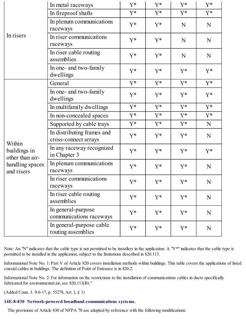
In risers
In metal raceways Y* Y* Y* Y*In fireproof shafts Y* Y* Y* Y*In plenum communicationsraceways Y* Y* N N
In riser communicationsraceways Y* Y* N N
In riser cable routingassemblies Y* Y* N N
In one- and two-familydwellings Y* Y* Y* Y*
Withinbuildings inother than air-handling spacesand risers
General Y* Y* Y* Y*In one- and two-familydwellings Y* Y* Y* Y*
In multifamily dwellings Y* Y* Y* Y*In non-concealed spaces Y* Y* Y* Y*Supported by cable trays Y* Y* Y* NIn distributing frames andcross-connect arrays Y* Y* Y* N
In any raceway recognizedin Chapter 3 Y* Y* Y* Y*
In plenum communicationsraceways Y* Y* Y* N
In riser communicationsraceways Y* Y* Y* N
In riser cable routingassemblies Y* Y* Y* N
In general-purposecommunications raceways Y* Y* Y* N
In general-purpose cablerouting assemblies Y* Y* Y* N
Note: An "N" indicates that the cable type is not permitted to be installers in the application. A "Y*" indicates that the cable type ispermitted to be installed in the application, subject to the limitations described in 820.113.
Informational Note No. 1: Part V of Article 820 covers installation methods within buildings. This table covers the applications of listedcoaxial cables in buildings. The definition of Point of Entrance is in 820.2.
Informational Note No. 2: For information on the restrictions to the installation of communications cables in ducts specificallyfabricated for environmental air, see 820.113(B)."
(Added Coun. J. 9-6-17, p. 55278, Art. I, § 1)
14E-8-830 Network-powered broadband communications systems.
The provisions of Article 830 of NFPA 70 are adopted by reference with the following modifications:

1. Revise subsection 830.110(A)(2) to read:
"Communications Raceways. Low-power network-powered broadband communication cables shall be permitted to be installed inplenum communications raceways, riser communications raceways, and general-purpose communications raceways, selected inaccordance with Table 800.154(b), listed in accordance with 800.182, and installed in accordance with 800.113."
2. Revise subsection 830.110(C) to read:
"Cable Routing Assemblies. Low-power network- powered broadband communications cables shall be permitted to be installed inriser cable routing assemblies, and general-purpose cable routing assemblies selected in accordance with Table 800.154(c), listed inaccordance with 800.182, and installed in accordance with 800.110(C) and 800.113."
3. Revise subsections 830.113 (B) through (I) to read:
"(B) Ducts Specifically Fabricated for Environmental Air. Wires and cables installed in ducts specifically fabricated forenvironmental air shall be installed in accordance with.22(B).
(C) Other Spaces Used for Environmental Air (Plenums). Wires and cables installed in other spaces used for environmentalair (plenums) shall be installed in accordance with 300.22(C).
(D) Risers - Cables in Vertical Runs. The following cables shall be permitted in vertical runs penetrating one or more floorsand in vertical runs in a shaft:
(1) Types BLP, BMR, and BLR
(2) Types BLP and BLR installed in the following:
a. Plenum communications raceways
b. Riser communications raceways
c. Riser cable routing assemblies
Informational Note: See 830.26 for firestop requirements for floor penetrations.
(E) Risers - Cables and Innerducts in Metal Raceways. The following cables and innerducts shall be permitted in a metalraceway in a riser with firestops at each floor:
(1) Types BLP, BMR, BLR, BM, BL, and BLX
(2) Types BLP, BLR, and BL installed in the following:
a. Plenum communications raceways (innerduct)
b. Riser communications raceways (innerduct)
c. General-purpose communications raceways (innerduct)
Informational Note: See 830.26 for firestop requirements for floor penetrations.
(F) Risers - Cables in Fireproof Shafts. The following cables shall be permitted to be installed in fireproof riser shafts withfirestops at each floor:
(1) Types BLP, BMR, BLR, BM, BL, and BLX
(2) Types BLP, BLR, and BL installed in the following:
a. Plenum communications raceways
b. Riser communications raceways
c. Riser cable routing assemblies
d. General-purpose communications raceways
e. General-purpose cable routing assemblies

Informational Note: See 830.26 for firestop requirements for floor penetrations.
(G) Risers - One- and Two-Family Dwellings. The following cables shall be permitted in one- and two- family dwellings:
(1) Types BLP, BMR, BLR, BM, BL, and BLX less than 10 mm (3/8 in.) in diameter
(2) Types BLP, BLR, and BL installed in the following:
a. Plenum communications raceways
b. Riser communications raceways
c. Riser cable routing assemblies
d. General-purpose communications raceways
e. General-purpose cable routing assemblies
Informational Note: See 830.26 for firestop requirements for floor penetrations.
(H) Cable Trays. The following cables shall be permitted to be supported by cable trays:
(1) Types BLP, BMR, BLR, BM, and BL
(2) Types BLP, BLR, and BL installed in the following:
a. Plenum communications raceways
b. Riser communications raceways
c. General-purpose communications raceways
(I) Other Building Locations. The following cables shall be permitted to be installed in building locations other than thosecovered in 830.113(B) through (H):
(1) Types BLP, BMR, BLR, BM, and BL
(2) Types BLP, BMR, BLR, BM, BL, and BLX installed in raceways recognized in Chapter 3
(3) Types BLP, BLR, and BL installed in the following:
a. Plenum communications raceways
b. Riser communications raceways
c. Riser cable routing assemblies
d. General-purpose communications raceways
e. General-purpose cable routing assemblies
(4) Type BLX less than 10 mm (3/8 in.) in diameter in one-and two-family dwellings
(5) Types BMU and BLU entering the building from outside and run in rigid metal conduit (RMC) or intermediate metal conduit(IMC) where the conduit is connected by a bonding conductor or grounding electrode conductor in accordance with 830.100(B)
Informational Note: This provision limits the length of Type BLX cable to 15.2 m (50 ft), while 830.90(B) requires that theprimary protector, or NIU with integral protection, be located as close as practicable to the point at which the cable enters the building.Therefore, in installations requiring a primary protector, or NIU with integral protection, Type BLX cable may not be permitted toextend 15.2 m (50 ft) into the building if it is practicable to place the primary protector closer than 15.2 m (50 ft) to the entrance point.
(6) A maximum length of 15.2 m (50 ft), within the building, of Type BLX cable entering the building from outside andterminating at an NIU or a primary protection location."
4. Revise Table 830.154(a) to read:
"Applications of Listed Network-Powered Broadband Cables in Buildings

ApplicationsListed Coaxial Cable Type
BLP BLR BL BMR BM BLX BMU ,BLU
In ductsspecificallyfabricated forenvironmentalair asdescribed in300.22(B)
In fabricated ducts asdescribed in300.22(B)
N N N N N N N
In metal raceway thatcomplies with300.22(B)
Y* Y* Y* Y* Y* Y* N
In other spacesused forenvironmentalair asdescribed in300.22(C)
In other spaces usedfor environmental airas described in300.22(C)
N N N N N N N
In metal raceway thatcomplies with300.22(C)
Y* Y* Y* Y* Y* Y* Y*
In risers
In vertical runs Y* Y* N Y* N N NIn metal raceways Y* Y* Y* Y* Y* Y* NIn fireproof shafts Y* Y* Y* Y* Y* Y* NIn plenumcommunicationsraceways
Y* Y* N N N N N
In risercommunicationsraceways
Y* Y* N N N N N
In riser cable routingassemblies Y* Y* N N N N N
In one- and two-family dwellings Y* Y* Y* Y* Y* Y* N
General Y* Y* Y* Y* Y* Y* NIn one- and two-family dwellings Y* Y* Y* Y* Y* Y* N
Supported by cabletrays Y* Y* Y* Y* Y* N N
In rigid metal conduit(RMC) andintermediate metalconduit (IMC)
Y* Y* Y* Y* Y* Y* Y*

Withinbuildings inother than air-handlingspaces andrisers
In any racewayrecognized in Chapter3
Y* Y* Y* Y* Y* Y* N
In plenumcommunicationsraceways
Y* Y* Y* N N N N
In risercommunicationsraceways
Y* Y* Y* N N N N
In riser cable routingassemblies Y* Y* Y* N N N N
In general-purposecommunicationsraceways
Y* Y* Y* N N N N
In general-purposecable routingassemblies
Y* Y* Y* N N N N
Note: An "N" indicates that the cable type shall not be permitted to be installed in the application. A "Y*" indicates that the cable typeshall be permitted to be installed in the application subject to the limitations described in 830.113.
Informational Note No. 1: Part V of Article 830 covers installation methods within buildings. This table covers the applications of listednetwork-powered broadband communications cables in buildings. The definition of Point of Entrance is in 830.2.
Informational Note No. 2: For information on the restrictions to the installation of network-powered broadband communications cablesin ducts specifically fabricated for environmental air, see 830.113(B)."
(Added Coun. J. 9-6-17, p. 55278, Art. I, § 1)
14E-8-840 Premises-powered broadband communications systems.
The provisions of Article 840 of NFPA 70 are adopted by reference with the following modifications:
1. Revise 840.2 To insert the following language after the definition of "Network Terminal":
"Nominal Current. The designated current per conductor as specified by equipment design.
Informational Note: One example of nominal current is 4-pair Power over Ethernet (PoE) applications based on IEEE 802.3-2015,IEEE Standard for Ethernet, that supplies current over 2 or 4 twisted pairs. The nominal current for 60-watt PoE power-sourcingequipment is 0.3 amperes per conductor, where the current in one conductor can be 0.36 amperes and another conductor can be 0.24amperes."
2. Revise 840.160 to read:
"Powering Circuits. Communications cables, in addition to carrying the communications circuit, shall also be permitted to carrycircuits for powering communications equipment. Installations of listed communications cables shall comply with 725.144 where listedcommunications cables are used in place of Class 2 and Class 3 cables.
Exception: Compliance with 725.144 shall not be required for installations of listed 4-pair communications cables wherethe nominal current does not exceed 0.3 amperes in any conductor."
(Added Coun. J. 9-6-17, p. 55278, Art. I, § 1)
CHAPTER 14E-9TABLES

14E-9-001 Percent of cross section of conduit and tubing for conductors and cables.
14E-9-002 Radius of conduit and tubing bends.
14E-9-004 Radius of conduit and tubing bends.
14E-9-005 Dimensions of insulated conductors and fixture wires and compact copper andaluminum building wire nominal dimensions and areas.
14E-9-008 Conductor properties.
14E-9-009 Alternating-current resistance and reactance for 600-volt cables, 3 phase, 60 Hz, 75°C(167°F) - Three single conductors in conduit.
14E-9-010 Conductor stranding.
14E-9-011 Class 2 and class 3 power source limitations.
14E-9-012 PLFA power source limitations.
14E-9-001 Percent of cross section of conduit and tubing for conductors and cables.
Chapter 9, Table 1 of NFPA 70 is adopted by reference with the following modification:
1. Revise Note 1 to read:
"See Informative Annex C for the maximum number of selected carrying-conductors (Types THHN, THWN, and THWN-2 only),all of the same size (total cross-sectional area including insulation) permitted in trade sizes of the applicable conduit or tubing."
(Added Coun. J. 9-6-17, p. 55278, Art. I, § 1)
14E-9-002 Radius of conduit and tubing bends.
Chapter 9, Table 2 of NFPA 70 are adopted by reference without modification.
(Added Coun. J. 9-6-17, p. 55278, Art. I, § 1)
14E-9-004 Radius of conduit and tubing bends.*
Chapter 9, Table 4 of NFPA 70 is adopted by reference without modification.
(Added Coun. J. 9-6-17, p. 55278, Art. I, § 1)
* Editor's note - The correct title for this section should be "Dimension and Percent Area of Conduit and Tubing". Future legislationwill correct the title.
14E-9-005 Dimensions of insulated conductors and fixture wires and compact copper and aluminum building wirenominal dimensions and areas.
Chapter 9, Tables 5 and 5A of NFPA 70 are adopted by reference without modification.
(Added Coun. J. 9-6-17, p. 55278, Art. I, § 1)
14E-9-008 Conductor properties.
Chapter 9, Table 8 of NFPA 70 is adopted by reference without modification.
(Added Coun. J. 9-6-17, p. 55278, Art. I, § 1)
14E-9-009 Alternating-current resistance and reactance for 600-volt cables, 3-phase, 60 Hz, 75°C (167°F) - Three singleconductors in conduit.
Chapter 9, Table 9 of NFPA 70 is adopted by reference without modification.
(Added Coun. J. 9-6-17, p. 55278, Art. I, § 1)
14E-9-010 Conductor stranding.

Chapter 9, Table 10 of NFPA 70 is adopted by reference without modification.
(Added Coun. J. 9-6-17, p. 55278, Art. I, § 1)
14E-9-011 Class 2 and class 3 power source limitations.
Chapter 9, Tables 11(A) and 11(B) of NFPA 70 are adopted by reference without modification.
(Added Coun. J. 9-6-17, p. 55278, Art. I, § 1)
14E-9-012 PLFA power source limitations.
Chapter 9, Tables 12(A) and 12(B) of NFPA 70 are adopted by reference without modification.
(Added Coun. J. 9-6-17, p. 55278, Art. I, § 1)
CHAPTER 14E-10INFORMATIVE ANNEXES
14E-10-010 Informative Annexes.
14E-10-010 Informative annexes.
These informative annexes are not part of the enforceable requirements of this Code, but are included for information purposes only.
1. Informative Annex Aof NFPA 70 is adopted by reference without modification.
2. Informative Annex B of NFPA 70 is adopted by reference without modification.
3. The following tables are adopted as Informative Annex C, entitled "Conduit and Tubing Fill Tables for Conductors and FixtureWires of the Same Size":
Table C.1 - Number of The Same Size Conductors in Trade Size of Conduit or Tubing Electrical Metallic Tubing (EMT)Conductor Types THHN, THWN, THWN-2 (Based on Table 1, Chapter 9)
100% 80% 70%1 2 3 4 5 6 7 8 9
14 1/2 1/2 1/2 1/2 1/2 1/2 1/2 1/2 1/212 1/2 1/2 1/2 1/2 1/2 1/2 1/2 1/2 1/210 1/2 1/2 1/2 1/2 1/2 3/4 3/4 3/4 3/48 1/2 1/2 1/2 3/4 3/4 3/4 1 1 16 1/2 1/2 3/4 3/4 1 1 1 1-1/4 1-1/44 1/2 3/4 1 1 1-1/4 1-1/4 1-1/4 1-1/2 1-1/23 1/2 1 1 1-1/4 1-1/4 1-1/4 1-1/2 1-1/2 22 1/2 1 1 1-1/4 1-1/4 1-1/2 1-1/2 2 21 1/2 1-1/4 1-1/4 1-1/4 1-1/2 2 2 2 2-1/2
1/0 1/2 1-1/4 1-1/4 1-1/2 2 2 2 2-1/2 2-1/22/0 3/4 1-1/4 1-1/2 2 2 2 2-1/2 2-1/2 2-1/23/0 3/4 1-1/2 1-1/2 2 2 2-1/2 2-1/2 2-1/2 34/0 3/4 1-1/2 2 2 2-1/2 2-1/2 2-1/2 3 3250 1 2 2 2-1/2 2-1/2 2-1/2 3 3 3

300 1 2 2 2-1/2 2-1/2 3 3 3-1/2 3-1/2350 1 2 2-1/2 2-1/2 3 3 3-1/2 3-1/2 3-1/2400 1-1/4 2-1/2 2-1/2 2-1/2 3 3 3-1/2 3-1/2 4500 1-1/4 2-1/2 2-1/2 3 3 3-1/2 4 4 - - -600 1-1/4 2-1/2 3 3 3-1/2 4 4 - - - - - -700 1-1/4 2-1/2 3 3-1/2 4 4 - - - - - - - - -750 1-1/2 3 3 3-1/2 4 - - - - - - - - - - - -800 1-1/2 3 3 3-1/2 4 - - - - - - - - - - - -900 1-1/2 3 3 4 - - - - - - - - - - - - - - -
1,000 1-1/2 3 3-1/2 4 - - - - - - - - - - - - - - -
Table C.1(A) - Number of The Same Size Compact Stranded Conductors in Trade Size of Conduit or Tubing ElectricalMetallic Tubing (EMT)
Conductor Types THHN (Based on Table 1, Chapter 9)
100% 80% 70%1 2 3 4 5 6 7 8 9
6 1/2 1/2 3/4 3/4 1 1 1 1-1/4 1-1/44 1/2 3/4 3/4 1 1-1/4 1-1/4 1-1/4 1-1/4 1-1/22 1/2 1 1 1-1/4 1-1/4 1-1/4 1-1/2 1-1/2 21 1/2 1 1-1/4 1-1/4 1-1/2 1-1/2 2 2 2
1/0 1/2 1-1/4 1-1/4 1-1/2 1-1/2 2 2 2 2-1/22/0 1/2 1-1/4 1-1/4 1-1/2 2 2 2 2-1/2 2-1/23/0 3/4 1-1/4 1-1/2 2 2 2 2-1/2 2-1/2 2-1/24/0 3/4 1-1/4 1-1/2 2 2 2-1/2 2-1/2 2-1/2 3250 3/4 2 2 2 2-1/2 2-1/2 3 3 3300 1 2 2 2-1/2 2-1/2 3 3 3 3-1/2350 1 2 2 2-1/2 2-1/2 3 3 3-1/2 3-1/2400 1 2 2-1/2 2-1/2 3 3 3-1/2 3-1/2 3-1/2500 1-1/4 2-1/2 2-1/2 2-1/2 3 3-1/2 3-1/2 4 4600 1-1/4 2-1/2 2-1/2 3 3-1/2 3-1/2 4 - - - - - -700 1-1/4 2-1/2 3 3 3-1/2 4 4 - - - - - -750 1-1/4 2-1/2 3 3 3-1/2 4 - - - - - - - - -
1,000 1-1/2 3 3 4 - - - - - - - - - - - - - - -
Table C.3 - Number of The Same Size Conductors in Trade Size of Conduit or Tubing Flexible Metal Conduit (FMC)
Conductor Types THHN, THWN, THWN-2 (Based on Table 1, Chapter 9)
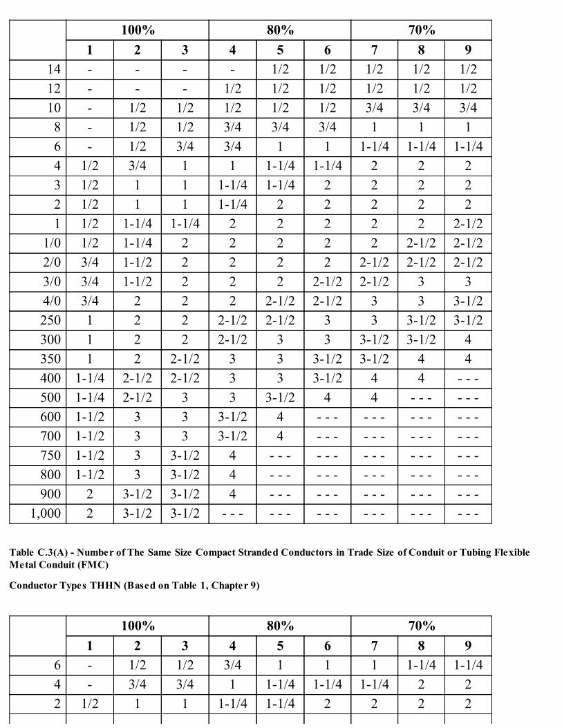
100% 80% 70%1 2 3 4 5 6 7 8 9
14 - - - - 1/2 1/2 1/2 1/2 1/212 - - - 1/2 1/2 1/2 1/2 1/2 1/210 - 1/2 1/2 1/2 1/2 1/2 3/4 3/4 3/48 - 1/2 1/2 3/4 3/4 3/4 1 1 16 - 1/2 3/4 3/4 1 1 1-1/4 1-1/4 1-1/44 1/2 3/4 1 1 1-1/4 1-1/4 2 2 23 1/2 1 1 1-1/4 1-1/4 2 2 2 22 1/2 1 1 1-1/4 2 2 2 2 21 1/2 1-1/4 1-1/4 2 2 2 2 2 2-1/2
1/0 1/2 1-1/4 2 2 2 2 2 2-1/2 2-1/22/0 3/4 1-1/2 2 2 2 2 2-1/2 2-1/2 2-1/23/0 3/4 1-1/2 2 2 2 2-1/2 2-1/2 3 34/0 3/4 2 2 2 2-1/2 2-1/2 3 3 3-1/2250 1 2 2 2-1/2 2-1/2 3 3 3-1/2 3-1/2300 1 2 2 2-1/2 3 3 3-1/2 3-1/2 4350 1 2 2-1/2 3 3 3-1/2 3-1/2 4 4400 1-1/4 2-1/2 2-1/2 3 3 3-1/2 4 4 - - -500 1-1/4 2-1/2 3 3 3-1/2 4 4 - - - - - -600 1-1/2 3 3 3-1/2 4 - - - - - - - - - - - -700 1-1/2 3 3 3-1/2 4 - - - - - - - - - - - -750 1-1/2 3 3-1/2 4 - - - - - - - - - - - - - - -800 1-1/2 3 3-1/2 4 - - - - - - - - - - - - - - -900 2 3-1/2 3-1/2 4 - - - - - - - - - - - - - - -
1,000 2 3-1/2 3-1/2 - - - - - - - - - - - - - - - - - -
Table C.3(A) - Number of The Same Size Compact Stranded Conductors in Trade Size of Conduit or Tubing FlexibleMetal Conduit (FMC)
Conductor Types THHN (Based on Table 1, Chapter 9)
100% 80% 70%1 2 3 4 5 6 7 8 9
6 - 1/2 1/2 3/4 1 1 1 1-1/4 1-1/44 - 3/4 3/4 1 1-1/4 1-1/4 1-1/4 2 22 1/2 1 1 1-1/4 1-1/4 2 2 2 2
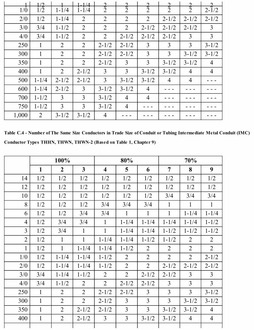
1 1/2 1 1-1/4 2 2 2 2 2 21/0 1/2 1-1/4 1-1/4 2 2 2 2 2 2-1/22/0 1/2 1-1/4 2 2 2 2 2-1/2 2-1/2 2-1/23/0 3/4 1-1/2 2 2 2 2-1/2 2-1/2 2-1/2 34/0 3/4 1-1/2 2 2 2-1/2 2-1/2 2-1/2 3 3250 1 2 2 2-1/2 2-1/2 3 3 3 3-1/2300 1 2 2 2-1/2 2-1/2 3 3 3-1/2 3-1/2350 1 2 2 2-1/2 3 3 3-1/2 3-1/2 4400 1 2 2-1/2 3 3 3-1/2 3-1/2 4 4500 1-1/4 2-1/2 2-1/2 3 3-1/2 3-1/2 4 4 - - -600 1-1/4 2-1/2 3 3-1/2 3-1/2 4 - - - - - - - - -700 1-1/2 3 3 3-1/2 4 4 - - - - - - - - -750 1-1/2 3 3 3-1/2 4 - - - - - - - - - - - -
1,000 2 3-1/2 3-1/2 4 - - - - - - - - - - - - - - -
Table C.4 - Number of The Same Size Conductors in Trade Size of Conduit or Tubing Intermediate Metal Conduit (IMC)
Conductor Types THHN, THWN, THWN-2 (Based on Table 1, Chapter 9)
100% 80% 70%1 2 3 4 5 6 7 8 9
14 1/2 1/2 1/2 1/2 1/2 1/2 1/2 1/2 1/212 1/2 1/2 1/2 1/2 1/2 1/2 1/2 1/2 1/210 1/2 1/2 1/2 1/2 1/2 1/2 3/4 3/4 3/48 1/2 1/2 1/2 3/4 3/4 3/4 1 1 16 1/2 1/2 3/4 3/4 1 1 1 1-1/4 1-1/44 1/2 3/4 3/4 1 1-1/4 1-1/4 1-1/4 1-1/4 1-1/23 1/2 3/4 1 1 1-1/4 1-1/4 1-1/2 1-1/2 1-1/22 1/2 1 1 1-1/4 1-1/4 1-1/2 1-1/2 2 21 1/2 1 1-1/4 1-1/4 1-1/2 2 2 2 2
1/0 1/2 1-1/4 1-1/4 1-1/2 2 2 2 2 2-1/22/0 1/2 1-1/4 1-1/4 1-1/2 2 2 2-1/2 2-1/2 2-1/23/0 3/4 1-1/4 1-1/2 2 2 2-1/2 2-1/2 3 34/0 3/4 1-1/2 2 2 2-1/2 2-1/2 3 3 3250 1 2 2 2-1/2 2-1/2 3 3 3 3-1/2300 1 2 2 2-1/2 3 3 3 3-1/2 3-1/2350 1 2 2-1/2 2-1/2 3 3 3-1/2 3-1/2 4400 1 2 2-1/2 3 3 3-1/2 3-1/2 4 4
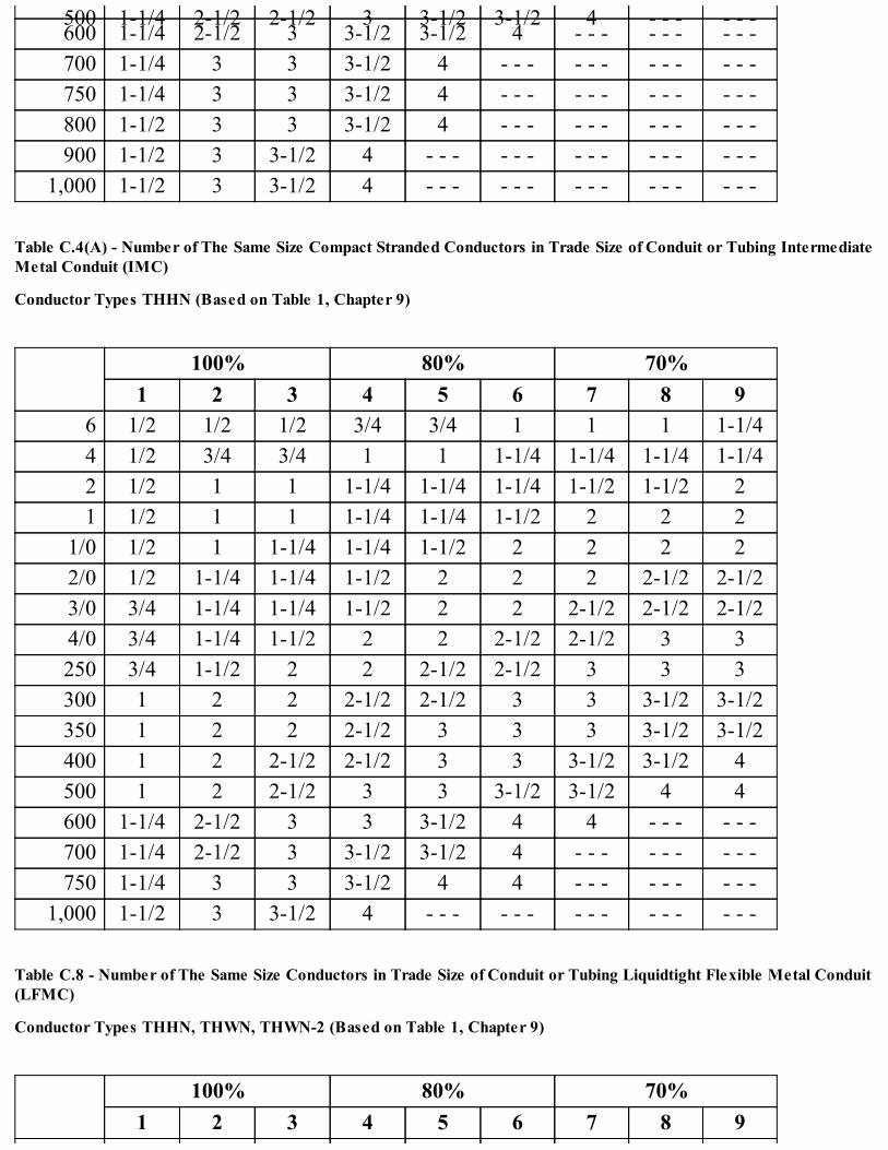
500 1-1/4 2-1/2 2-1/2 3 3-1/2 3-1/2 4 - - - - - -600 1-1/4 2-1/2 3 3-1/2 3-1/2 4 - - - - - - - - -700 1-1/4 3 3 3-1/2 4 - - - - - - - - - - - -750 1-1/4 3 3 3-1/2 4 - - - - - - - - - - - -800 1-1/2 3 3 3-1/2 4 - - - - - - - - - - - -900 1-1/2 3 3-1/2 4 - - - - - - - - - - - - - - -
1,000 1-1/2 3 3-1/2 4 - - - - - - - - - - - - - - -
Table C.4(A) - Number of The Same Size Compact Stranded Conductors in Trade Size of Conduit or Tubing IntermediateMetal Conduit (IMC)
Conductor Types THHN (Based on Table 1, Chapter 9)
100% 80% 70%1 2 3 4 5 6 7 8 9
6 1/2 1/2 1/2 3/4 3/4 1 1 1 1-1/44 1/2 3/4 3/4 1 1 1-1/4 1-1/4 1-1/4 1-1/42 1/2 1 1 1-1/4 1-1/4 1-1/4 1-1/2 1-1/2 21 1/2 1 1 1-1/4 1-1/4 1-1/2 2 2 2
1/0 1/2 1 1-1/4 1-1/4 1-1/2 2 2 2 22/0 1/2 1-1/4 1-1/4 1-1/2 2 2 2 2-1/2 2-1/23/0 3/4 1-1/4 1-1/4 1-1/2 2 2 2-1/2 2-1/2 2-1/24/0 3/4 1-1/4 1-1/2 2 2 2-1/2 2-1/2 3 3250 3/4 1-1/2 2 2 2-1/2 2-1/2 3 3 3300 1 2 2 2-1/2 2-1/2 3 3 3-1/2 3-1/2350 1 2 2 2-1/2 3 3 3 3-1/2 3-1/2400 1 2 2-1/2 2-1/2 3 3 3-1/2 3-1/2 4500 1 2 2-1/2 3 3 3-1/2 3-1/2 4 4600 1-1/4 2-1/2 3 3 3-1/2 4 4 - - - - - -700 1-1/4 2-1/2 3 3-1/2 3-1/2 4 - - - - - - - - -750 1-1/4 3 3 3-1/2 4 4 - - - - - - - - -
1,000 1-1/2 3 3-1/2 4 - - - - - - - - - - - - - - -
Table C.8 - Number of The Same Size Conductors in Trade Size of Conduit or Tubing Liquidtight Flexible Metal Conduit(LFMC)
Conductor Types THHN, THWN, THWN-2 (Based on Table 1, Chapter 9)
100% 80% 70%1 2 3 4 5 6 7 8 9

14 - - - - - - - - 1/212 - - - - - 1/2 1/2 1/2 1/210 - - - 1/2 1/2 1/2 3/4 3/4 3/48 - 1/2 1/2 3/4 3/4 3/4 1 1 16 - 1/2 3/4 3/4 1 1 1 1-1/4 1-1/44 - 3/4 1 1 1-1/4 1-1/4 1-1/4 1-1/2 1-1/23 - 1 1 1-1/4 1-1/4 1-1/4 1-1/2 1-1/2 22 - 1 1 1-1/4 1-1/4 1-1/2 1-1/2 2 21 1/2 1-1/4 1-1/4 1-1/4 1-1/2 2 2 2 2-1/2
1/0 1/2 1-1/4 1-1/4 1-1/2 2 2 2 2-1/2 2-1/22/0 3/4 1-1/4 1-1/2 2 2 2 2-1/2 2-1/2 33/0 3/4 1-1/2 1-1/2 2 2 2-1/2 2-1/2 3 34/0 3/4 1-1/2 2 2 2-1/2 2-1/2 3 3 3250 1 2 2 2-1/2 2-1/2 3 3 3-1/2 3-1/2300 1 2 2 2-1/2 3 3 3-1/2 3-1/2 4350 1 2 2-1/2 3 3 3-1/2 3-1/2 4 4400 1-1/4 2-1/2 2-1/2 3 3 3-1/2 4 4 - - -500 1-1/4 2-1/2 3 3 3-1/2 4 4 - - - - - -600 1-1/4 3 3 3-1/2 4 4 - - - - - - - - -700 1-1/4 3 3 3-1/2 4 - - - - - - - - - - - -750 1-1/2 3 3 4 4 - - - - - - - - - - - -800 1-1/2 3 3-1/2 4 - - - - - - - - - - - - - - -900 1-1/2 3 3-1/2 4 - - - - - - - - - - - - - - -
1,000 2 3-1/2 3-1/2 - - - - - - - - - - - - - - - - - -
Table C.8(A) - Number of The Same Size Compact Stranded Conductors in Trade Size of Conduit or Tubing LiquidtightFlexible Metal Conduit (LFMC)
Conductor Types THHN (Based on Table 1, Chapter 9)
100% 80% 70%1 2 3 4 5 6 7 8 9
6 - 1/2 3/4 3/4 1 1 1 1-1/4 1-1/44 - 3/4 3/4 1 1-1/4 1-1/4 1-1/4 1-1/4 1-1/22 - 1 1 1-1/4 1-1/4 1-1/4 1-1/2 2 21 1/2 1 1-1/4 1-1/4 1-1/2 1-1/2 2 2 2
1/0 1/2 1-1/4 1-1/4 1-1/4 1-1/2 2 2 2 2-1/22/0 1/2 1-1/4 1-1/4 1-1/2 2 2 2-1/2 2-1/2 2-1/2

3/0 3/4 1-1/4 1-1/2 2 2 2-1/2 2-1/2 2-1/2 34/0 3/4 1-1/2 1-1/2 2 2-1/2 2-1/2 2-1/2 3 3250 3/4 2 2 2-1/2 2-1/2 3 3 3 3-1/2300 1 2 2 2-1/2 3 3 3 3-1/2 3-1/2350 1 2 2-1/2 2-1/2 3 3 3-1/2 3-1/2 4400 1 2 2-1/2 3 3 3-1/2 3-1/2 4 4500 1-1/4 2-1/2 2-1/2 3 3 3-1/2 4 4 - - -600 1-1/4 2-1/2 3 3 3-1/2 4 - - - - - - - - -700 1-1/4 3 3 3-1/2 4 4 - - - - - - - - -750 1-1/4 3 3 3-1/2 4 - - - - - - - - - - - -
1,000 1-1/2 3 3-1/2 4 - - - - - - - - - - - - - - -
Table C.9 - Number of The Same Size Conductors in Trade Size of Conduit or Tubing Rigid Metal Conduit (RMC)
Conductor Types THHN, THWN, THWN-2 (Based on Table 1, Chapter 9)
100% 80% 70%1 2 3 4 5 6 7 8 9
14 1/2 1/2 1/2 1/2 1/2 1/2 1/2 1/2 1/212 1/2 1/2 1/2 1/2 1/2 1/2 1/2 1/2 1/210 1/2 1/2 1/2 1/2 1/2 1/2 3/4 3/4 3/48 1/2 1/2 1/2 3/4 3/4 3/4 1 1 16 1/2 1/2 3/4 3/4 1 1 1 1-1/4 1-1/44 1/2 3/4 1 1 1-1/4 1-1/4 1-1/4 1-1/2 1-1/23 1/2 1 1 1-1/4 1-1/4 1-1/4 1-1/2 1-1/2 22 1/2 1 1 1-1/4 1-1/4 1-1/2 1-1/2 2 21 1/2 1-1/4 1-1/4 1-1/4 1-1/2 2 2 2 2-1/2
1/0 1/2 1-1/4 1-1/4 1-1/2 2 2 2 2-1/2 2-1/22/0 3/4 1-1/4 1-1/2 2 2 2 2-1/2 2-1/2 33/0 3/4 1-1/2 1-1/2 2 2 2-1/2 2-1/2 3 34/0 3/4 1-1/2 2 2 2-1/2 2-1/2 3 3 3250 1 2 2 2-1/2 2-1/2 3 3 3-1/2 3-1/2300 1 2 2 2-1/2 3 3 3-1/2 3-1/2 4350 1 2 2-1/2 3 3 3-1/2 3-1/2 4 4400 1 2 2-1/2 3 3 3-1/2 3-1/2 4 5500 1-1/4 2-1/2 3 3 3-1/2 4 4 5 5600 1-1/4 3 3 3-1/2 4 4 5 5 5700 1-1/4 3 3 3-1/2 4 5 5 5 6

750 1-1/2 3 3 3-1/2 4 5 5 6 6800 1-1/2 3 3-1/2 4 5 5 5 6 6900 1-1/2 3 3-1/2 4 5 5 6 6 6
1,000 1-1/2 3-1/2 3-1/2 4 5 5 6 6 - - -
Table C.9(A) - Number of The Same Size Compact Stranded Conductors in Trade Size of Conduit or Tubing Rigid MetalConduit (RMC)
Conductor Types THHN (Based on Table 1, Chapter 9)
100% 80% 70%1 2 3 4 5 6 7 8 9
6 1/2 1/2 3/4 3/4 3/4 1 1 1 1-1/44 1/2 3/4 3/4 1 1 1-1/4 1-1/4 1-1/4 1-1/22 1/2 1 1 1-1/4 1-1/4 1-1/4 1-1/2 1-1/2 21 1/2 1 1-1/4 1-1/4 1-1/2 1-1/2 2 2 2
1/0 1/2 1-1/4 1-1/4 1-1/4 1-1/2 2 2 2 2-1/22/0 1/2 1-1/4 1-1/4 1-1/2 2 2 2 2-1/2 2-1/23/0 3/4 1-1/4 1-1/2 2 2 2 2-1/2 2-1/2 34/0 3/4 1-1/2 1-1/2 2 2 2-1/2 2-1/2 3 3250 3/4 1-1/2 2 2 2-1/2 3 3 3 3-1/2300 1 2 2 2-1/2 3 3 3 3-1/2 3-1/2350 1 2 2 2-1/2 3 3 3-1/2 3-1/2 4400 1 2 2-1/2 3 3 3-1/2 3-1/2 4 4500 1-1/4 2-1/2 2-1/2 3 3 3-1/2 4 4 5600 1-1/4 2-1/2 3 3 3-1/2 4 5 5 5700 1-1/4 3 3 3-1/2 4 4 5 5 5750 1-1/4 3 3 3-1/2 4 5 5 5 5
1,000 1-1/2 3 3-1/2 4 5 5 6 6 6
Table C.10 - Number of The Same Size Conductors in Trade Size of Conduit or Tubing Rigid PVC Conduit, Schedule 80
Conductor Types THHN, THWN, THWN-2 (Based on Table 1, Chapter 9)
100% 80% 70%1 2 3 4 5 6 7 8 9
14 1/2 1/2 1/2 1/2 1/2 1/2 1/2 1/2 1/212 1/2 1/2 1/2 1/2 1/2 1/2 3/4 3/4 3/410 1/2 1/2 1/2 1/2 3/4 3/4 3/4 1 18 1/2 1/2 3/4 3/4 1 1 1 1-1/4 1-1/4

6 1/2 3/4 3/4 1 1 1-1/4 1-1/4 1-1/4 1-1/44 1/2 1 1 1-1/4 1-1/4 1-1/4 1-1/2 1-1/2 23 1/2 1 1 1-1/4 1-1/4 1-1/2 1-1/2 2 22 1/2 1 1-1/4 1-1/4 1-1/2 1-1/2 2 2 21 3/4 1-1/4 1-1/4 1-1/2 2 2 2 2-1/2 2-1/2
1/0 3/4 1-1/4 1-1/2 2 2 2 2-1/2 2-1/2 2-1/22/0 3/4 1-1/2 1-1/2 2 2 2-1/2 2-1/2 3 33/0 3/4 1-1/2 2 2 2-1/2 2-1/2 3 3 34/0 1 2 2 2-1/2 2-1/2 3 3 3 3-1/2250 1 2 2 2-1/2 3 3 3-1/2 3-1/2 4300 1-1/4 2 2-1/2 3 3 3-1/2 3-1/2 4 4350 1-1/4 2-1/2 2-1/2 3 3 3-1/2 4 4 5400 1-1/4 2-1/2 2-1/2 3 3-1/2 3-1/2 4 5 5500 1-1/4 2-1/2 3 3-1/2 3-1/2 4 5 5 5600 1-1/2 3 3 3-1/2 4 5 5 5 6700 1-1/2 3 3-1/2 4 5 5 5 6 6750 1-1/2 3 3-1/2 4 5 5 5 6 6800 1-1/2 3 3-1/2 4 5 5 6 6 6900 2 3-1/2 3-1/2 5 5 5 6 6 - - -
1,000 2 3-1/2 4 5 5 6 6 - - - - - -
Table C.10(A) - Number of The Same Size Compact Stranded Conductors in Trade Size of Conduit or Tubing Rigid PVCConduit, Schedule 80
Conductor Types THHN (Based on Table 1, Chapter 9)
100% 80% 70%1 2 3 4 5 6 7 8 9
6 1/2 3/4 3/4 1 1 1 1-1/4 1-1/4 1-1/44 1/2 1 1 1-1/4 1-1/4 1-1/4 1-1/2 1-1/2 1-1/22 1/2 1 1-1/4 1-1/4 1-1/4 1-1/2 2 2 21 1/2 1-1/4 1-1/4 1-1/2 1-1/2 2 2 2 2-1/2
1/0 3/4 1-1/4 1-1/4 1-1/2 2 2 2 2-1/2 2-1/22/0 3/4 1-1/4 1-1/2 2 2 2 2-1/2 2-1/2 33/0 3/4 1-1/2 1-1/2 2 2 2-1/2 2-1/2 3 34/0 1 1-1/2 2 2 2-1/2 2-1/2 3 3 3250 1 2 2 2-1/2 3 3 3 3-1/2 3-1/2300 1 2 2 2-1/2 3 3 3-1/2 3-1/2 4
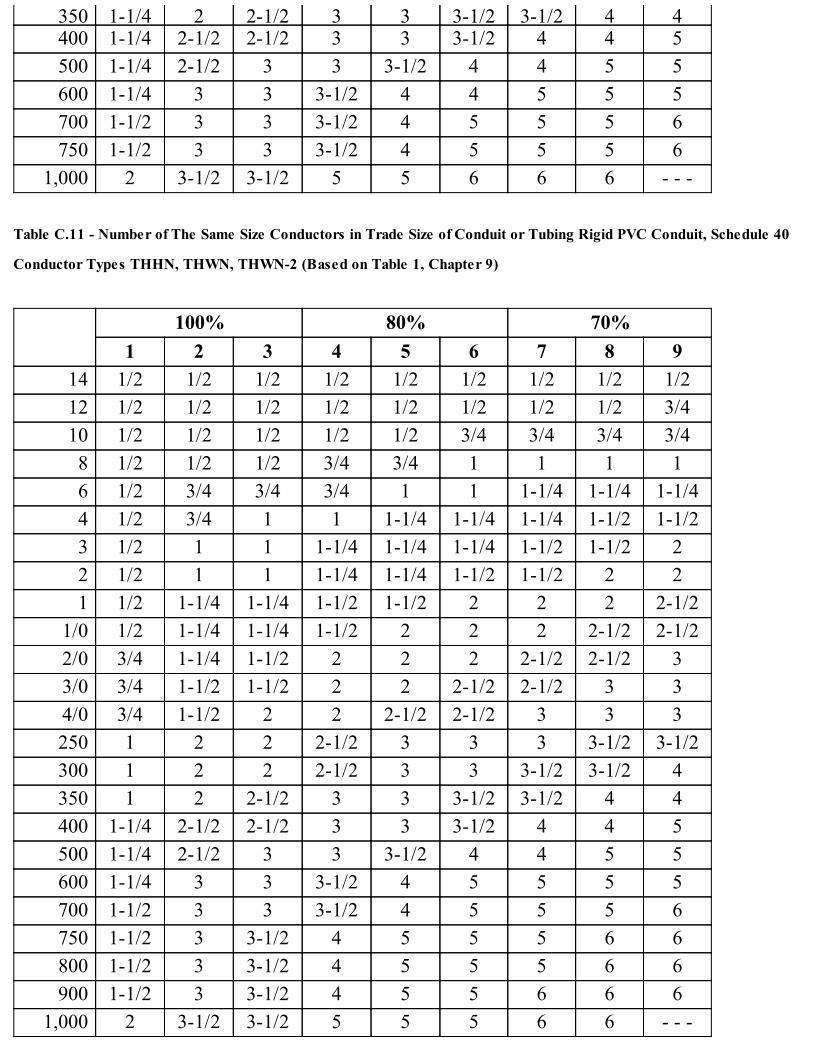
350 1-1/4 2 2-1/2 3 3 3-1/2 3-1/2 4 4400 1-1/4 2-1/2 2-1/2 3 3 3-1/2 4 4 5500 1-1/4 2-1/2 3 3 3-1/2 4 4 5 5600 1-1/4 3 3 3-1/2 4 4 5 5 5700 1-1/2 3 3 3-1/2 4 5 5 5 6750 1-1/2 3 3 3-1/2 4 5 5 5 6
1,000 2 3-1/2 3-1/2 5 5 6 6 6 - - -
Table C.11 - Number of The Same Size Conductors in Trade Size of Conduit or Tubing Rigid PVC Conduit, Schedule 40
Conductor Types THHN, THWN, THWN-2 (Based on Table 1, Chapter 9)
100% 80% 70%1 2 3 4 5 6 7 8 9
14 1/2 1/2 1/2 1/2 1/2 1/2 1/2 1/2 1/212 1/2 1/2 1/2 1/2 1/2 1/2 1/2 1/2 3/410 1/2 1/2 1/2 1/2 1/2 3/4 3/4 3/4 3/48 1/2 1/2 1/2 3/4 3/4 1 1 1 16 1/2 3/4 3/4 3/4 1 1 1-1/4 1-1/4 1-1/44 1/2 3/4 1 1 1-1/4 1-1/4 1-1/4 1-1/2 1-1/23 1/2 1 1 1-1/4 1-1/4 1-1/4 1-1/2 1-1/2 22 1/2 1 1 1-1/4 1-1/4 1-1/2 1-1/2 2 21 1/2 1-1/4 1-1/4 1-1/2 1-1/2 2 2 2 2-1/2
1/0 1/2 1-1/4 1-1/4 1-1/2 2 2 2 2-1/2 2-1/22/0 3/4 1-1/4 1-1/2 2 2 2 2-1/2 2-1/2 33/0 3/4 1-1/2 1-1/2 2 2 2-1/2 2-1/2 3 34/0 3/4 1-1/2 2 2 2-1/2 2-1/2 3 3 3250 1 2 2 2-1/2 3 3 3 3-1/2 3-1/2300 1 2 2 2-1/2 3 3 3-1/2 3-1/2 4350 1 2 2-1/2 3 3 3-1/2 3-1/2 4 4400 1-1/4 2-1/2 2-1/2 3 3 3-1/2 4 4 5500 1-1/4 2-1/2 3 3 3-1/2 4 4 5 5600 1-1/4 3 3 3-1/2 4 5 5 5 5700 1-1/2 3 3 3-1/2 4 5 5 5 6750 1-1/2 3 3-1/2 4 5 5 5 6 6800 1-1/2 3 3-1/2 4 5 5 5 6 6900 1-1/2 3 3-1/2 4 5 5 6 6 6
1,000 2 3-1/2 3-1/2 5 5 5 6 6 - - -

Table C.11(A) - Number of The Same Size Compact Stranded Conductors in Trade Size of Conduit or Tubing Rigid PVCConduit, Schedule 40
Conductor Types THHN (Based on Table 1, Chapter 9)
100% 80% 70%1 2 3 4 5 6 7 8 9
6 1/2 1/2 3/4 3/4 1 1 1 1-1/4 1-1/44 1/2 3/4 1 1 1-1/4 1-1/4 1-1/4 1-1/4 1-1/22 1/2 1 1 1-1/4 1-1/4 1-1/2 1-1/2 1-1/2 21 1/2 1 1-1/4 1-1/4 1-1/2 1-1/2 2 2 2
1/0 1/2 1-1/4 1-1/4 1-1/2 1-1/2 2 2 2 2-1/22/0 3/4 1-1/4 1-1/4 1-1/2 2 2 2 2-1/2 2-1/23/0 3/4 1-1/4 1-1/2 2 2 2-1/2 2-1/2 2-1/2 34/0 3/4 1-1/2 1-1/2 2 2-1/2 2-1/2 3 3 3250 1 2 2 2-1/2 2-1/2 3 3 3 3-1/2300 1 2 2 2-1/2 3 3 3 3-1/2 3-1/2350 1 2 2 2-1/2 3 3 3-1/2 3-1/2 4400 1 2 2-1/2 3 3 3-1/2 3-1/2 4 4500 1-1/4 2-1/2 2-1/2 3 3-1/2 3-1/2 4 4 5600 1-1/4 2-1/2 3 3 3-1/2 4 5 5 5700 1-1/4 3 3 3-1/2 4 5 5 5 5750 1-1/4 3 3 3-1/2 4 5 5 5 6
1,000 1-1/2 3 3-1/2 4 5 5 6 6 6
4. Informative Annex Dof NFPA 70 is adopted by reference without modification.
5. Informative Annex F of NFPA 70 is adopted by reference without modification.
6. Informative Annex G of NFPA 70 is adopted by reference without modification.
7. Informative Annex I of NFPA 70 is adopted by reference without modification.
(Added Coun. J. 9-6-17, p. 55278, Art. I, § 1)
Disclaimer:This Code of Ordinances and/or any other documents that appear on this site may not reflect the most current legislationadopted by the Municipality. American Legal Publishing Corporation provides these documents for informational purposesonly. These documents should not be relied upon as the definitive authority for local legislation. Additionally, the formattingand pagination of the posted documents varies from the formatting and pagination of the official copy. The official printedcopy of a Code of Ordinances should be consulted prior to any action being taken.
For further information regarding the official version of any of this Code of Ordinances or other documents posted on thissite, please contact the Municipality directly or contact American Legal Publishing toll-free at 800-445-5588.
© 2018 American Legal Publishing Corporation
