titan v3: assembly and calibration manual - gate e · 1 / 17. titan v3: assembly and calibration...
TRANSCRIPT
1 / 17
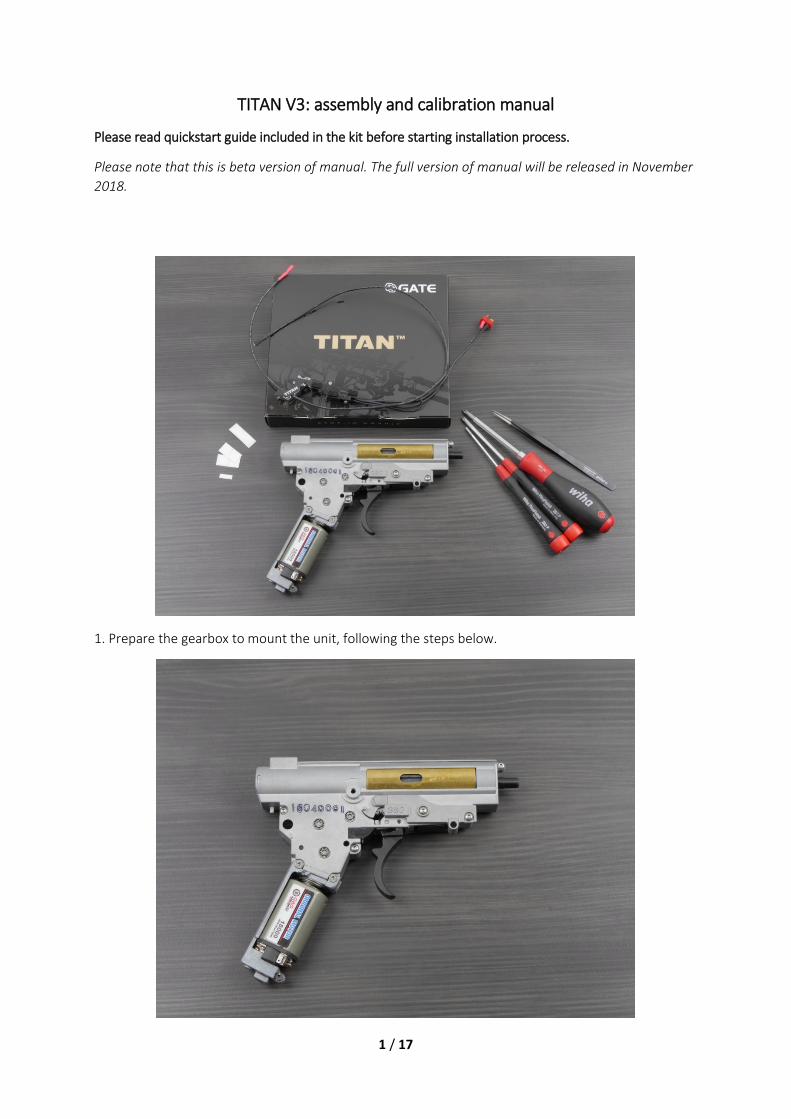
TITAN V3: assembly and calibration manual
Please read quickstart guide included in the kit before starting installation process.
Please note that this is beta version of manual. The full version of manual will be released in November 2018.
1. Prepare the gearbox to mount the unit, following the steps below.

2 / 17
1.1 Disassemble the motor.
1.2. Dismantle the gearbox external parts (sector gear cover, trigger lock, screws).
3 / 17
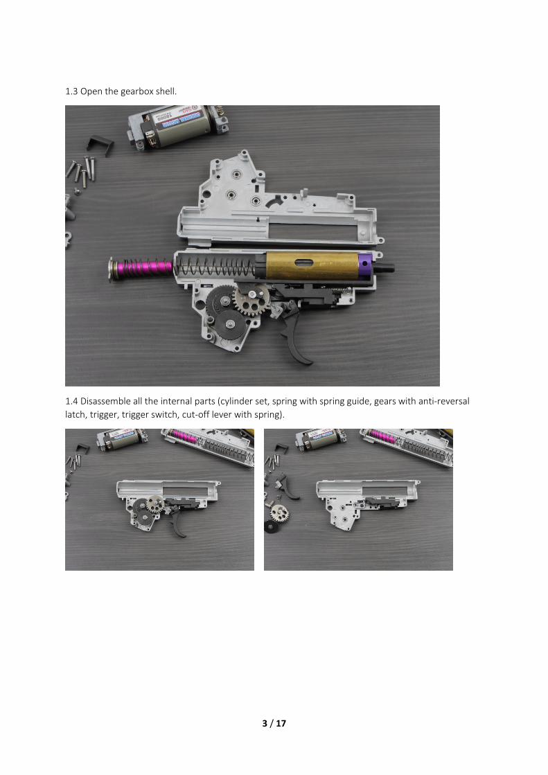
1.3 Open the gearbox shell.
1.4 Disassemble all the internal parts (cylinder set, spring with spring guide, gears with anti-reversal latch, trigger, trigger switch, cut-off lever with spring).
4 / 17
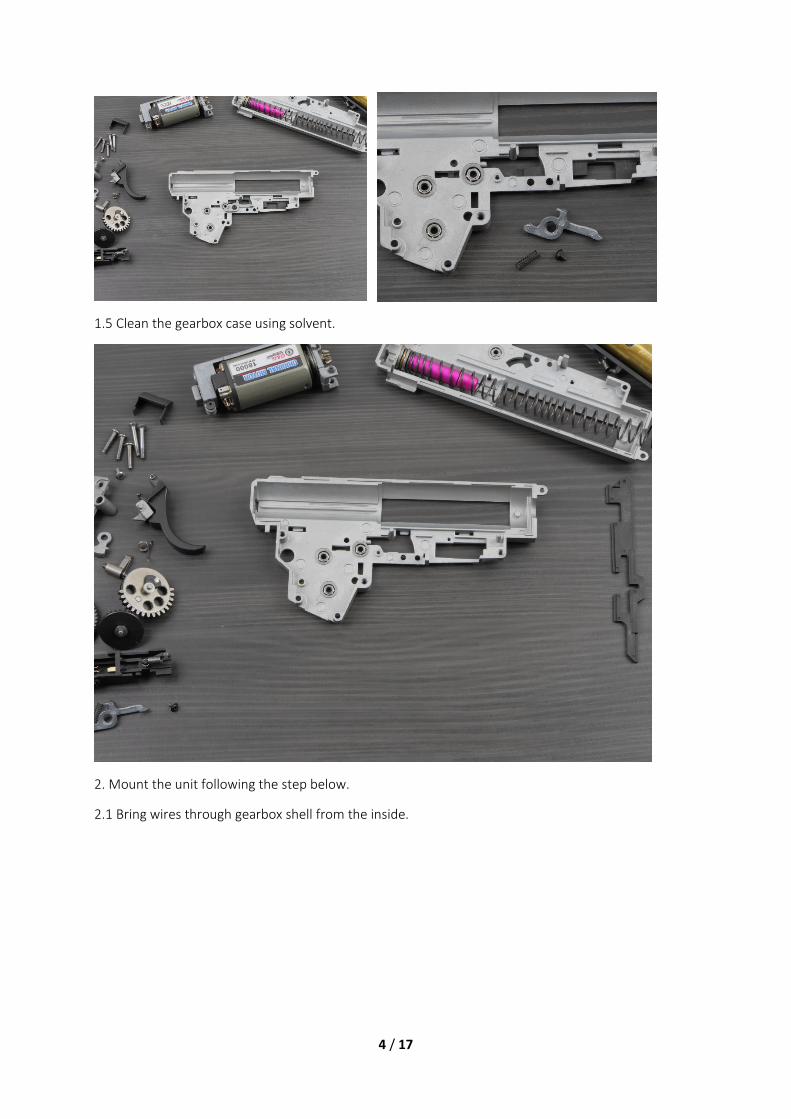
1.5 Clean the gearbox case using solvent.
2. Mount the unit following the step below.
2.1 Bring wires through gearbox shell from the inside.
5 / 17
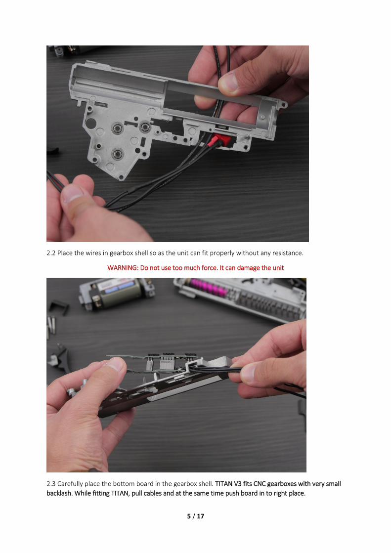
2.2 Place the wires in gearbox shell so as the unit can fit properly without any resistance.
WARNING: Do not use too much force. It can damage the unit
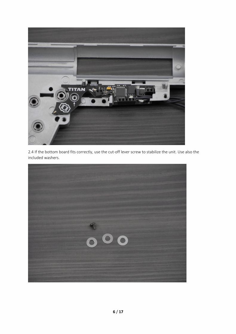
2.3 Carefully place the bottom board in the gearbox shell. TITAN V3 fits CNC gearboxes with very small backlash. While fitting TITAN, pull cables and at the same time push board in to right place.
6 / 17
2.4 If the bottom board fits correctly, use the cut-off lever screw to stabilize the unit. Use also the included washers.
7 / 17
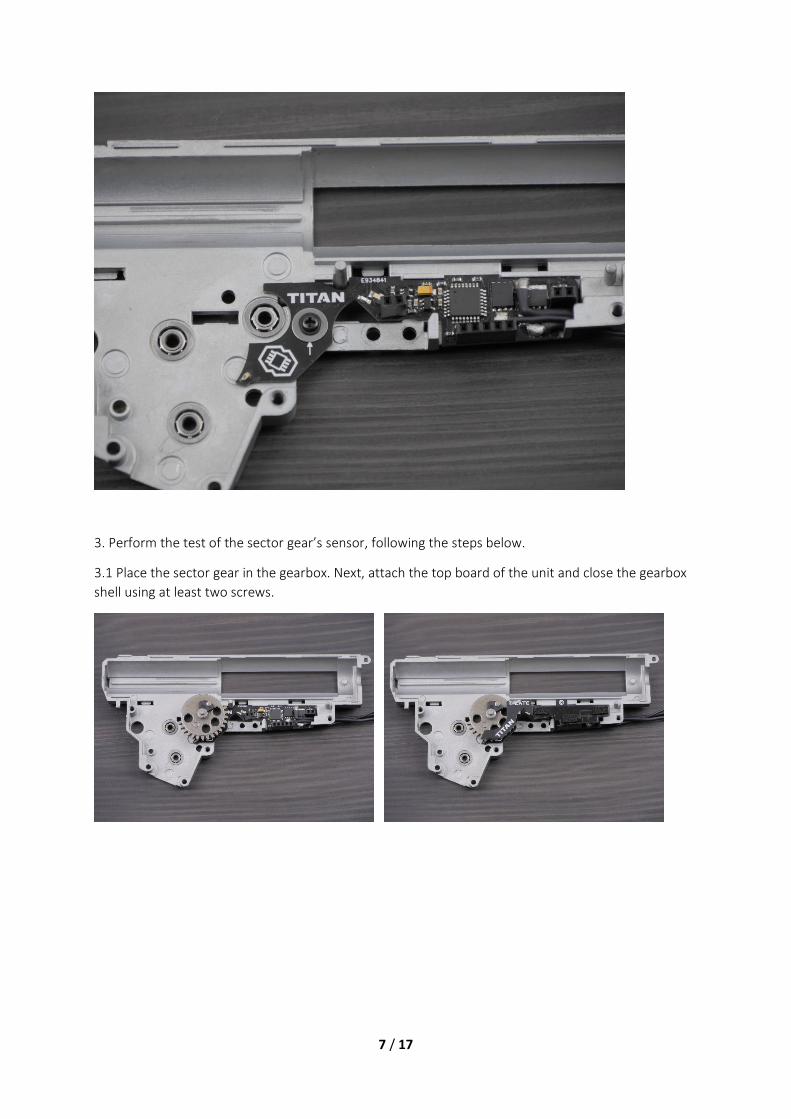
3. Perform the test of the sector gear’s sensor, following the steps below.
3.1 Place the sector gear in the gearbox. Next, attach the top board of the unit and close the gearbox shell using at least two screws.

8 / 17
3.2 Connect the unit to the GATE Control Station using USB cable and USB-Link. Next, go to SENSORS tab. While moving the gear observe behavior of the gear sensor. Please note that TITAN V3 is not compatible with Tactical Programming Card.

9 / 17
The sensor state should change as in the pictures below. If it does not, please contact us.

10 / 17
4. Modify the trigger elements following the steps below.
4.1 Use solvent to clean trigger elements. Next, take the stickers shown in the picture below.
4.2 Paste the smaller sticker (Trigger sticker) on surface shown in the photo below.
4.3 Paste one Trigger anti-backlash sticker inside the moving element of the trigger.
The stickers reduce the space between the trigger and the moving element, so as the trigger works more precisely. Installation kit includes three different thickness stickers.
11 / 17
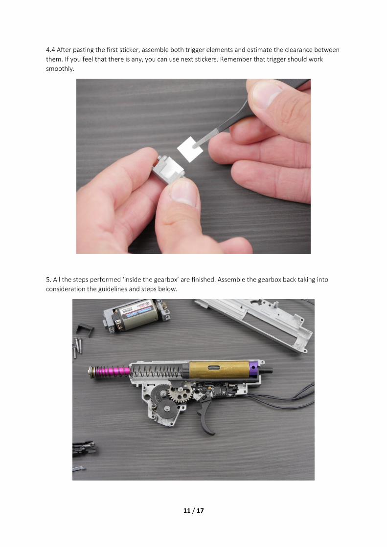
4.4 After pasting the first sticker, assemble both trigger elements and estimate the clearance between them. If you feel that there is any, you can use next stickers. Remember that trigger should work smoothly.
5. All the steps performed ‘inside the gearbox’ are finished. Assemble the gearbox back taking into consideration the guidelines and steps below.
12 / 17
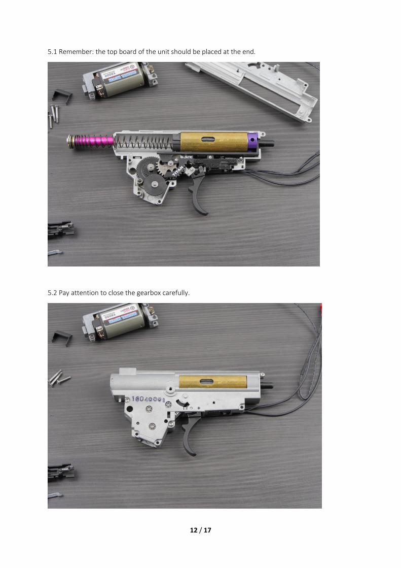
5.1 Remember: the top board of the unit should be placed at the end.
5.2 Pay attention to close the gearbox carefully.
13 / 17
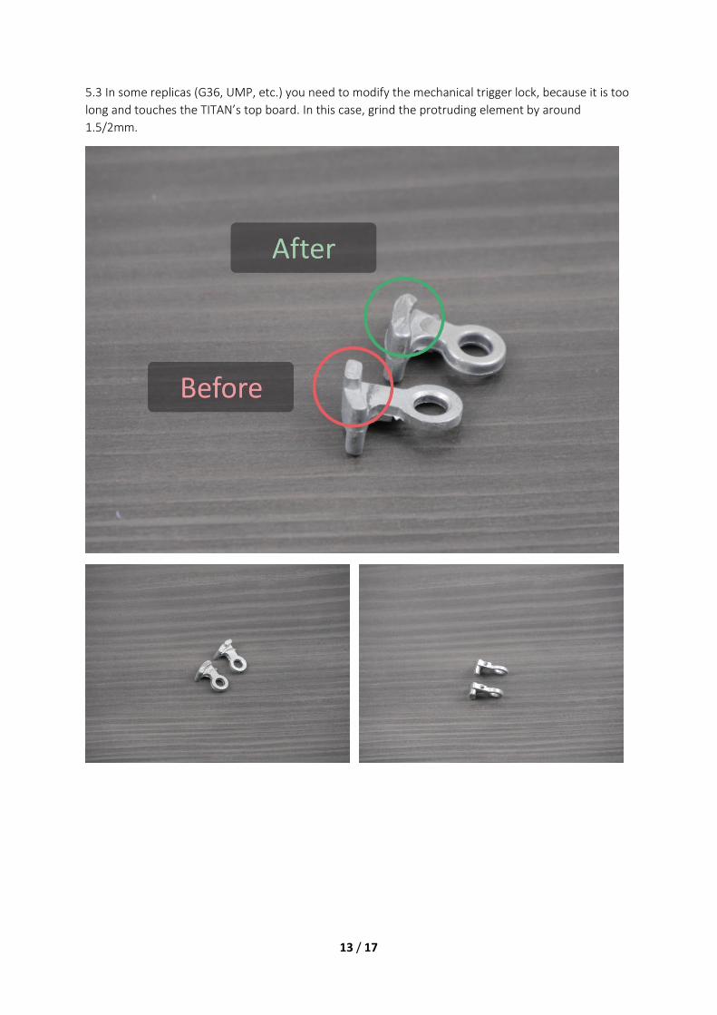
5.3 In some replicas (G36, UMP, etc.) you need to modify the mechanical trigger lock, because it is too long and touches the TITAN’s top board. In this case, grind the protruding element by around 1.5/2mm.

14 / 17
5.4 After the modification, check if the mechanical trigger lock touches the TITAN top board. If it does not touch the board, you can take the next step.
6. After installing the remaining gearbox external components, go to the wiring placement. You can use the picture below or your previous wiring as a suggestion.
15 / 17
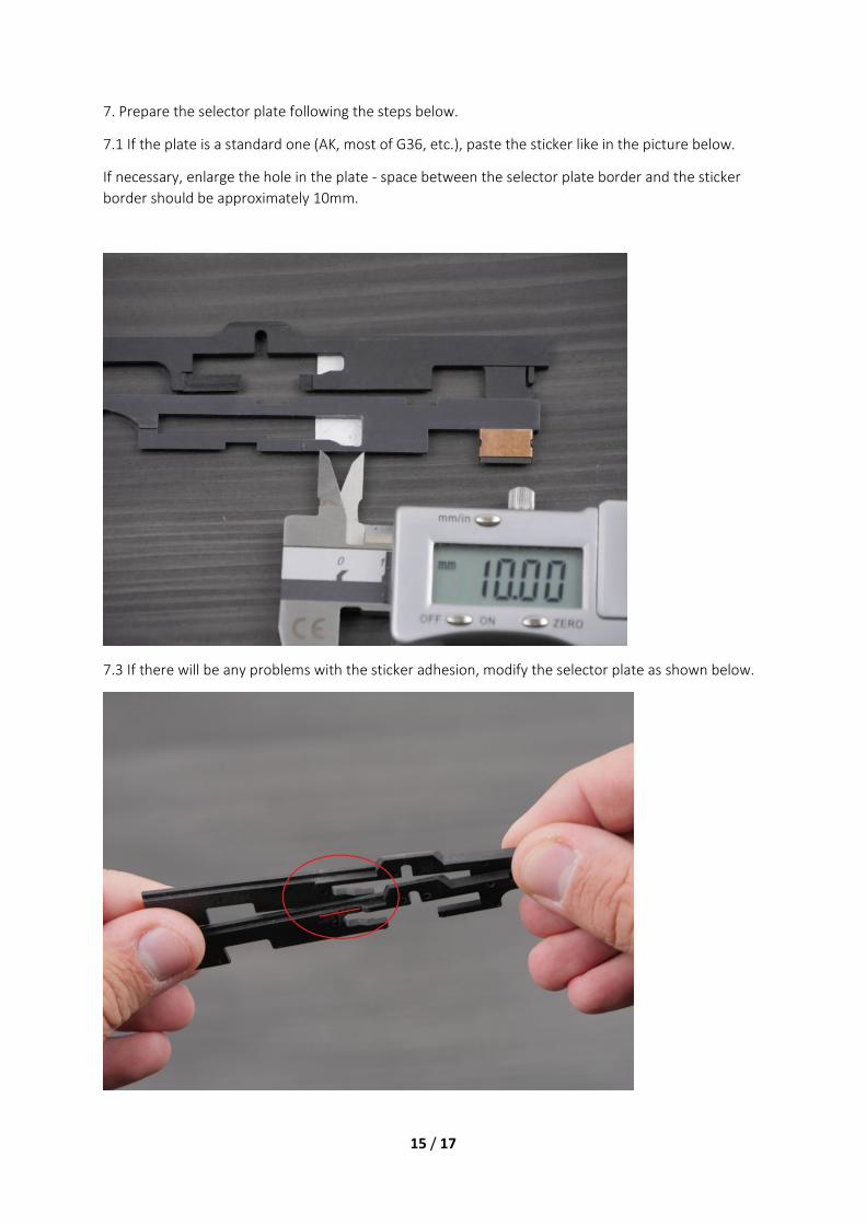
7. Prepare the selector plate following the steps below.
7.1 If the plate is a standard one (AK, most of G36, etc.), paste the sticker like in the picture below.
If necessary, enlarge the hole in the plate - space between the selector plate border and the sticker border should be approximately 10mm.
7.3 If there will be any problems with the sticker adhesion, modify the selector plate as shown below.

16 / 17
8. Finish the gun assembly.
9. Connect TITAN to PC using USB-Link. Remember to use most updated GATE Control Station version.
10. If your gun is completely assembled, perform the sensor calibration following the calibration instructions from GATE Control Station.
WARNING!
Calibrate the trigger and selector sensors only after the gearbox is mounted in the replica body.

17 / 17
If you have any questions, please feel free to ask: [email protected]
Online help: https://www.facebook.com/gatee/