titan moves the world™
TRANSCRIPT

Titan Tire Customer CarePHONE: 1.800.USA-BEAR FAX: 515.265.9301E-MAIL: [email protected] WEB: www.titan-intl.comTitan Tire Corporation • Des Moines, Iowa
Titan Wheel Customer CarePHONE: 276.496.3107 or 217.221.4430 E-MAIL: [email protected]
Volume 6 09.2013© 2013 Titan Tire Corporation. All Rights Reserved. Division of Titan International, Inc. TWI, Quincy, IL. Materials and specifications are subject to change without notice. Goodyear is a registered trademark of The Goodyear Tire & Rubber Company.
NO TIRE WORKS WITHOUT THE WHEEL — THEY ARE A TOTAL SYSTEMTitan is the only company with the ability to design, test and produce both wheels and tires for mining, agriculture, construction and forestry markets.
T i T a n M o v e s T h e W o r l d™
OTR TIRESvo
lUM
e 6
1.800.USA-BEAR | www.titan-intl.com
OTR
DAT
AB
OO
K VO
LUM
E 6
TIT
AN
TIR
E CO
RPO
RATI
ON
1.
800.
USA
-BEA
R

Underground MiningMaterial Handling
Radial OTR
Earthmoving
Grader
Loader - Dozer
Container Handling
Backhoe
Forestry
Skid Steer
Smooth
Contents
Load & Inflation Tables
Safety Section
Radial OTRTitan 007 MFT ............................................................ 3Titan TG2 (G-2) ........................................................... 4Titan TGS2 (G-2) ......................................................... 5Titan TGL2 (G-2/L-2) ................................................... 5Titan TGD2 (E-2/L-2) ................................................... 5Titan STL3 (E-3/L-3) Dual Purpose Tire ........................ 6Titan MXL (E-3/L-3) ..................................................... 7Titan STL2+ (E-3T/L-3T) Dual Purpose Tire ................... 7Titan DTH4 (E-4) Haul Truck Tire ................................. 8Titan DTE4 (E-4) Haul Truck Tire .................................. 8Titan LDR250 (L-5) ...................................................... 9Titan LDR150 (L-4) ...................................................... 9
EarthmovingTitan LCM (E-3) ..........................................................10Titan ND LCM (E-3) ....................................................10Titan ND LCM MCS (E-3) ...........................................10Titan SL 100 (E-3) ......................................................11Titan MXL (E-3/L-3) ....................................................12Titan Super Rigger (E-3/L-3) .......................................12Titan Super Rigger LSW (E-3) .....................................12Titan CM100 (E-3) .....................................................13Titan Grizz 100 (E-3) ..................................................13Titan XG-3 (E-3) .........................................................13Titan Super LCM (E-4) ................................................14Titan ND Super LCM (E-4) ..........................................14Titan CM 150 (E-4) ....................................................14Titan Quarry Special CM 150 (E-4) .............................15Titan CH 150 (E-4/L-4) ..............................................16Titan Super Sand Flotation (E-7) .................................16
GraderTitan Loader Grader/Loader Grader III (G-2) or (L-2/G-2) ..................................................17Titan Motor Grader HD(L-2/G-2) ................................17Titan Super Grader (G-2/L-2) ......................................18Titan LSW G8L (G-2) ..................................................18Titan HD 2000II (G-2) ................................................18
Loader - DozerTitan Loader Dozer II (L-2) ..........................................19Titan Lift Rigger II (L-2) ...............................................19Titan Super Rigger (L-3/E-3) .......................................20Titan ND LCM (L-3) (L-3/E-3) .......................................20Titan MCSLCM (L-3/E-3) .............................................20Titan LD 100 (L-3) ......................................................21Titan SL 100 (E-3) ......................................................21Titan MXL (E-3/L-3) ....................................................21Titan Super LCM (L-4) ............................................... 22Titan LD 150 (L-4) ..................................................... 22Titan CH 150 (L-4/E-4) ............................................. 22Titan CM 150 (L-4) .................................................... 23Titan LS 150 ............................................................. 23Titan LD 250 (L-5) CRB .............................................. 23Titan LD 250 Belted (L-5) 7x7 ................................... 23Titan LD 250 Haf-Trac (L-5/L-5S) CRB .........................24Titan LD 250 Haf-Trac Belted (L-5/L-5S) 7x7................24Titan LD 250 Super Smooth (L-5S) CRB ......................24Titan LD 250 Super Smooth (L-5S) CAB .....................24Titan LD 250 Super Smooth Belted (L-5S) 7x7 ............24
Container HandlingTitan LCM (L-3) ..........................................................25Titan ND LCM (L-3) ....................................................25Titan Super LCM (L-4) ................................................26Titan CH 150 (L-4) .....................................................26Titan CM 150 (L-4) .....................................................26Titan Super Smooth (L-4S) .........................................27Titan Super Smooth (L-5S) .........................................27
Underground Mining/ Material HandlingTitan LD 250 Super Smooth UGM (L-5S) ....................28Titan Industrial Deep Traction ....................................28Titan T44 .................................................................. 29Titan TT472 .............................................................. 29Titan T40 ............................................................. 29Titan PWT ................................................................ 30
ForestryGoodyear Logger Lug III (LS-2)...................................31Goodyear Logger Lug III HD (LS-2) .............................32Goodyear Logger Lug III Flotation (HF-4) ...................32
BackhoeGoodyear IT510 (R-4) Radial ......................................33Goodyear IT520 (R-4) Radial ......................................33Goodyear IT525 (R-4) Radial ......................................33Goodyear IT530 (R-4) Radial ......................................33Goodyear IT515 HS (R-4) .......................................... 34Goodyear IT525 (R-4) ............................................... 34Goodyear Industrial Tractor (R-4) ...............................35Goodyear Industrial Sure Grip (R-4) ...........................35Titan Industrial Tractor Lug (R-4) ................................35Titan Industrial Contractor (R-4) ................................35Titan Industrial Tractor Lug II (R-4) .............................35Titan Grizz LSWG9F (R-4) ......................................... 36Goodyear Laborer (F-3) ..............................................37Goodyear Multi Rib (F-3)............................................37Titan Contractor (F-3) ................................................37Titan Industrial Front Tractor (F-3) ..............................37Goodyear Sure Grip Implement (I-3) ......................... 38Goodyear Sure Grip Lug (I-3) .................................... 38Titan Contractor (I-3) ................................................ 38Titan Contractor II (I-3) ............................................. 38Titan TI422 (I-3) ........................................................ 38Titan Grizz LSW G2E (I-3) ......................................... 38
Skid SteerGoodyear IT323........................................................ 39Goodyear Sure Grip Lug ........................................... 39Titan Contractor FWD .............................................. 40Titan Trac Loader ...................................................... 40Titan Trac Loader Chevron ........................................ 40Titan HD2000 ........................................................... 40Titan HD2000 II ........................................................ 40Titan Ultimate ............................................................42Titan H/E ...................................................................42Titan Grizz LSWG9A ................................................. 43
SmoothGoodyear Smooth Industrial ..................................... 44Goodyear Compactor ............................................... 44Titan Road Roller/Road Roller II ................................. 44
Load & Inflation Tables ......................................... 45Industrial Loads ..................................................... 78Logger Lug/Flotation Loads ................................. 79Material Handling Loads ...................................... 82Safety ............................................................. S:1 (83)
www.titan-intl.com

3
800.USA.BEAR
Radial OTR
Titan 007 MFT• Large contact area provides damage resistance• Self cleaning grooves provide excellent traction• Tie-bars provide lug stabilization, resulting in even tread wear• Custom compounds available• No sipes available on some designs
UlTra class radial
SizeCompound/
ConstructionCatalog Number
Sipes/No Sipes
Industry Code
Load/Speed Index
Load Rating
RimWidthCode
FlangeHeightCode
Outside Diameter in (mm)
Section Width
in (mm)
Tread Depth
in (mm)Load @ Inflation
lbs @ PSI (kg @ bar)TMPH(TKPH)
59/80R63 HV MHV278 Sipes E-3 268 B 2 * 44.00 5.0 158.5 (4026) 57.4 (1461) 89/32 (71) 220,500 @ 110 (100,000 @ 7.5) 1355 (1978)59/80R63 WV MWV278 Sipes E-3 268 B 2 * 44.00 5.0 158.5 (4026) 57.4 (1461) 89/32 (71) 220,500 @ 110 (100,000 @ 7.5) 1084 (1582)59/80R63 CV MFV278 Sipes E-3 268 B 2 * 44.00 5.0 158.5 (4026) 57.4 (1461) 89/32 (71) 220,500 @ 110 (100,000 @ 7.5) 813 (1187)59/80R63 SV MSV278 Sipes E-3 268 B 2 * 44.00 5.0 158.5 (4026) 57.4 (1461) 89/32 (71) 220,500 @ 110 (100,000 @ 7.5) ---59/80R63 H2 MH2278 No Sipes E-3 268 B 2 * 44.00 5.0 158.5 (4026) 57.4 (1461) 89/32 (71) 220,500 @ 110 (100,000 @ 7.5) 1287 (1879)59/80R63 W2 MW2278 No Sipes E-3 268 B 2 * 44.00 5.0 158.5 (4026) 57.4 (1461) 89/32 (71) 220,500 @ 110 (100,000 @ 7.5) 1030 (1503)59/80R63 C2 MF2278 No Sipes E-3 268 B 2 * 44.00 5.0 158.5 (1461) 57.4 (1461) 89/32 (71) 220,500 @ 110 (100,000 @ 7.5) 772 (1127)59/80R63 S2 MS2278 No Sipes E-3 268 B 2 * 44.00 5.0 158.5 (4026) 57.4 (1461) 89/32 (71) 220,500 @ 110 (100,000 @ 7.5) ---
59/80R63 HD MHD278 Sipes E-4 268 B 2 * 44.00 5.0 158.5 (4026) 57.4 (1461) 146/32 (116) 220,500 @ 110 (100,000 @ 7.5) 1016 (1483)59/80R63 WD MWD278 Sipes E-4 268 B 2 * 44.00 5.0 158.5 (4026) 57.4 (1461) 146/32 (116) 220,500 @ 110 (100,000 @ 7.5) 813 (1186)59/80R63 CD MFD278 Sipes E-4 268 B 2 * 44.00 5.0 158.5 (4026) 57.4 (1461) 146/32 (116) 220,500 @ 110 (100,000 @ 7.5) 610 (890)59/80R63 H5 MH5278 No Sipes E-4 268 B 2 * 44.00 5.0 158.5 (4026) 57.4 (1461) 146/32 (116) 220,500 @ 110 (100,000 @ 7.5) 965 (1409)59/80R63 W5 MW5278 No Sipes E-4 268 B 2 * 44.00 5.0 158.5 (4026) 57.4 (1461) 146/32 (116) 220,500 @ 110 (100,000 @ 7.5) 772 (1127)59/80R63 C5 MF5278 No Sipes E-4 268 B 2 * 44.00 5.0 158.5 (4026) 57.4 (1461) 146/32 (116) 220,500 @ 110 (100,000 @ 7.5) 579 (845)
53/80R63 HV MHV23M Sipes E-4 261 B 2 * 36.00, 38.00 5.0 148.8 (3780) 53 (1346) 130/32 (103) 182,000 @ 110 (82,500 @ 7.5) 1001 (1461)53/80R63 WV MWV23M Sipes E-4 261 B 2 * 36.00, 38.00 5.0 148.8 (3780) 53 (1346) 130/32 (103) 182,000 @ 110 (82,500 @ 7.5) 801 (1169)53/80R63 CV MFV23M Sipes E-4 261 B 2 * 36.00, 38.00 5.0 148.8 (3780) 52 (1346) 130/32 (103) 182,000 @ 110 (82,500 @ 7.5) 601 (877)53/80R63 H2 MH223M No Sipes E-4 261 B 2 * 36.00, 38.00 5.0 148.8 (3780) 53 (1346) 130/32 (103) 182,000 @ 110 (82,500 @ 7.5) 951 (1388)53/80R63 W2 MW223M No Sipes E-4 261 B 2 * 36.00, 38.00 5.0 148.8 (3780) 53 (1346) 130/32 (103) 182,000 @ 110 (82,500 @ 7.5) 761 (1110)53/80R63 C2 MF223M No Sipes E-4 261 B 2 * 36.00, 38.00 5.0 148.8 (3780) 53 (1346) 130/32 (103) 182,000 @ 110 (82,500 @ 7.5) 571 (833)
46/90R57 HV MHV276 Sipes E-4 252 B 2 * 32.00, 29.00 6.0 142.1 (3609) 46.0 (1168) 105/32 (83) 139,000 @105 (63,000 @7.3) 853 (1246)46/90R57 WV MWV276 Sipes E-4 252 B 2 * 32.00, 29.00 6.0 142.1 (3609) 46.0 (1168) 105/32 (83) 139,000 @105 (63,000 @7.3) 683 (996)46/90R57 CV MFV276 Sipes E-4 252 B 2 * 32.00, 29.00 6.0 142.1 (3609) 46.0 (1168) 105/32 (83) 139,000 @105 (63,000 @7.3) 512 (747)46/90R57 H2 MH2276 No Sipes E-4 252 B 2 * 32.00, 29.00 6.0 142.1 (3609) 46.0 (1168) 105/32 (83) 139,000 @105 (63,000 @7.3) 810 (1183)46/90R57 W2 MW2276 No Sipes E-4 252 B 2 * 32.00, 29.00 6.0 142.1 (3609) 46.0 (1168) 105/32 (83) 139,000 @105 (63,000 @7.3) 648 (947)46/90R57 C2 MF2276 No Sipes E-4 252 B 2 * 32.00, 29.00 6.0 142.1 (3609) 46.0 (1168) 105/32 (83) 139,000 @105 (63,000 @7.3) 486 (710)
40.00R57 HV MHV240 Sipes E-4 250 B 2 * 29.00, 32.00 6.0 142.1 (3609) 43.2 (1097) 105/32 (83) 132,500 @ 105 (60,000 @ 7.3) 813 (1186)40.00R57 WV MWV240 Sipes E-4 250 B 2 * 29.00, 32.00 6.0 142.1 (3609) 43.2 (1097) 105/32 (83) 132,500 @ 105 (60,000 @ 7.3) 650 (949)40.00R57 CV MFV240 Sipes E-4 250 B 2 * 29.00, 32.00 6.0 142.1 (3609) 43.2 (1097) 105/32 (83) 132,500 @ 105 (60,000 @ 7.3) 488 (712)40.00R57 H2 MH2240 No Sipes E-4 250 B 2 * 29.00, 32.00 6.0 142.1 (3609) 43.2 (1097) 105/32 (83) 132,500 @ 105 (60,000 @ 7.3) 772 (1127)40.00R57 W2 MW2240 No Sipes E-4 250 B 2 * 29.00, 32.00 6.0 142.1 (3609) 43.2 (1097) 105/32 (83) 132,500 @ 105 (60,000 @ 7.3) 618 (902)40.00R57 C2 MF2240 No Sipes E-4 250 B 2 * 29.00, 32.00 6.0 142.1 (3609) 43.2 (1097) 105/32 (83) 132,500 @ 105 (60,000 @ 7.3) 463 (676)
40.00R57 HR MHR240 Sipes E-4 250 B 2 * 29.00, 32.00 6.0 142.1 (3609) 43.2 (1097) 105/32 (83) 132,500 @ 105 (60,000 @ 7.3) 813 (1186)40.00R57 WR MWR240 Sipes E-4 250 B 2 * 29.00, 32.00 6.0 142.1 (3609) 43.2 (1097) 105/32 (83) 132,500 @ 105 (60,000 @ 7.3) 650 (949)40.00R57 CR MFR240 Sipes E-4 250 B 2 * 29.00, 32.00 6.0 142.1 (3609) 43.2 (1097) 105/32 (83) 132,500 @ 105 (60,000 @ 7.3) 488 (712)
R - Rounded shoulder design
No Sipes Sipes

4
www.titan-intl.com
Radial OTR
SizeCompound/
ConstructionCatalog Number
Sipes/No Sipes
Industry Code
Load/Speed Index
Load Rating
RimWidthCode
FlangeHeightCode
Outside Diameter in (mm)
Section Width
in (mm)
Tread Depth
in (mm)Load @ Inflation
lbs @ PSI (kg @ bar)TMPH(TKPH)
40.00R57 H4 MH4240 No Sipes E-4 250 B 2 * 29.00, 32.00 6.0 142.1 (3609) 43.2 (1097) 105/32 (83) 132,500 @ 105 (60,000 @ 7.3) 772 (1127)40.00R57 W4 MW4240 No Sipes E-4 250 B 2 * 29.00, 32.00 6.0 142.1 (3609) 43.2 (1097) 105/32 (83) 132,500 @ 105 (60,000 @ 7.3) 618 (902)40.00R57 C4 MF4240 No Sipes E-4 250 B 2 * 29.00, 32.00 6.0 142.1 (3609) 43.2 (1097) 105/32 (83) 132,500 @ 105 (60,000 @ 7.3) 463 (676)
37.00R57 HV MHV237 Sipes E-4 + 245 B 2 * 27.00, 29.00 6.0 136.0 (3455) 40.0 (1016) 125/32 (99) 113,500 @ 105 (51,500 @ 7.3) 716 (1046)37.00R57 WV MWV237 Sipes E-4 + 245 B 2 * 27.00, 29.00 6.0 136.0 (3455) 40.0 (1016) 125/32 (99) 113,500 @ 105 (51,500 @ 7.3) 573 (837)37.00R57 CV MFV237 Sipes E-4 + 245 B 2 * 27.00, 29.00 6.0 136.0 (3455) 40.0 (1016) 125/32 (99) 113,500 @ 105 (51,500 @ 7.3) 430 (628)37.00R57 H2 MH2237 No Sipes E-4 + 245 B 2 * 27.00, 29.00 6.0 136.0 (3455) 40.0 (1016) 125/32 (99) 113,500 @ 105 (51,500 @ 7.3) 681 (994)37.00R57 W2 MW2237 No Sipes E-4 + 245 B 2 * 27.00, 29.00 6.0 136.0 (3455) 40.0 (1016) 125/32 (99) 113,500 @ 105 (51,500 @ 7.3) 545 (795)37.00R57 C2 MF2237 No Sipes E-4 + 245 B 2 * 27.00, 29.00 6.0 136.0 (3455) 40.0 (1016) 125/32 (99) 113,500 @ 105 (51,500 @ 7.3) 408 (596)
33.00R51 HE MHT2R3 Sipes E-4 235 B 2 * 24.00 5.0 120.5 (3061) 35.2 (894) 98/32 (78) 85,500 @ 105 (38,750 @ 7.3) 568 (829)33.00R51 WE MWT2R3 Sipes E-4 235 B 2 * 24.00 5.0 120.5 (3061) 35.2 (894) 98/32 (78) 85,500 @ 105 (38,750 @ 7.3) 470 (687)33.00R51 CE MFT2R3 Sipes E-4 235 B 2 * 24.00 5.0 120.5 (3061) 35.2 (894) 98/32 (78) 85,500 @ 105 (38,750 @ 7.3) 353 (515)33.00R51 H2 MH22R3 No Sipes E-4 235 B 2 * 24.00 5.0 120.5 (3061) 35.2 (894) 98/32 (78) 85,500 @ 105 (38,750 @ 7.3) 540 (788)33.00R51 W2 MW22R3 No Sipes E-4 235 B 2 * 24.00 5.0 120.5 (3061) 35.2 (894) 98/32 (78) 85,500 @ 105 (38,750 @ 7.3) 447 (652)33.00R51 C2 MF22R3 No Sipes E-4 235 B 2 * 24.00 5.0 120.5 (3061) 35.2 (894) 98/32 (78) 85,500 @ 105 (38,750 @ 7.3) 335 (489)
27.00R49 HE MHT2R9 Sipes E-4 223 B 2 * 19.50 4.0 106.7 (2703) 28.6 (726) 86/32 (68) 60,000 @ 105 (27,250 @7.3) 433 (631)27.00R49 WE MWT2R9 Sipes E-4 223 B 2 * 19.50 4.0 106.7 (2703) 28.6 (726) 86/32 (68) 60,000 @ 105 (27,250 @7.3) 346 (505)27.00R49 CE MFT2R9 Sipes E-4 223 B 2 * 19.50 4.0 106.7 (2703) 28.6 (726) 86/32 (68) 60,000 @ 105 (27,250 @7.3) 260 (379)27.00R49 H2 MH22R9 No Sipes E-4 223 B 2 * 19.50 4.0 106.7 (2703) 28.6 (726) 86/32 (68) 60,000 @ 105 (27,250 @7.3) 411 (600)27.00R49 W2 MW22R9 No Sipes E-4 223 B 2 * 19.50 4.0 106.7 (2703) 28.6 (726) 86/32 (68) 60,000 @ 105 (27,250 @7.3) 329 (480)27.00R49 C2 MF22R9 No Sipes E-4 223 B 2 * 19.50 4.0 106.7 (2703) 28.6 (726) 86/32 (68) 60,000 @ 105 (27,250 @7.3) 247 (360)
Titan TG2 (G-2)• Exceptional traction design• Non-directional tread pattern provides long tread life• Open tread pattern provides excellent self-cleaning
Tire SizeCompound/
ConstructionCatalog Number
Industry Code
Load/Speed Index
Load Rating
RimCode
Flange Code
Outside Diameterin (mm)
Section Width
in (mm)
Section Width
Loadedin (mm)
Static Loaded Radiusin (mm)
Gross Footprint
Areain2 (cm2)
Tread Depth
in (mm)
Load/Inflationlb @ PSI
(kg @ bar)
14.00R24TG WE PGW1R4 G-2 153 A8 1 * 10.00VA 1.7 53.1 (1348) 14.3 (362)
16.9 (429) 24.1 (612) 153
(990)32/32 (25.4)
8,050 @ 54 (3,650 @ 3.8)
007 MFT continued

5
800.USA.BEAR
Radial OTR
Titan TGl2 (G-2/l-2)• Non-directional tread pattern provides long tread life• Open tread pattern provides excellent self-cleaning and traction
Titan TGs2 (G-2)• All season tread pattern• Aggressive tread pattern provides excellent traction and self-cleaning on all
surfaces• Siping provides excellent traction in all conditions, especially mud, snow and ice
Tire SizeCompound/
ConstructionCatalogNumber
Industry Code
Load/Speed Index
Load Rating
RimCode
Flange Code
Outside Diameterin (mm)
Section Width
in (mm)
Section Width
Loadedin (mm)
Static Loaded Radiusin (mm)
Gross Footprint
Areain2 (cm2)
Tread Depth
in (mm)
Load/Inflationlb @ PSI
(kg @ bar)
17.5R25 WE EUWA17 L-2 176 A2 1 * 14.00 1.5 52.6 (1337) 17.5 (445)
20.0 (507)
23.5 (596)
230 (1487)
35/32 (27.8)
15,700 @ 73 (7,100 @ 5.0)
G-2 153 A8 1 * 14.00 1.5 52.6 (1337) 17.5 (445)
19.5 (496)
24.0 (610) 191 (1235)
35/32 (27.8)
8,050 @ 44 (3,650 @ 3.0)
Tire SizeCompound/
ConstructionCatalog Number
Industry Code
Load/Speed Index
LoadRating
RimCode
Flange Code
Outside Diameterin (mm)
Section Width
in (mm)
Section Width
Loadedin (mm)
Static Loaded Radiusin (mm)
Gross Footprint
Areain2 (cm2)
Tread Depth
in (mm)
Load/Inflationlb @ PSI
(kg @ bar)
14.00R24TG WE PSW1R4 G-2 153 A8 1 * 10.00VA 1.7 53.1 (1348) 14.3 (362)
16.9 (429) 24.1 (612) 153
(990)32/32 (25.4)
8,050 @ 54 (3,650 @ 3.8)
Titan TGd2 (E-2/l-2)• Directional tread design for excellent forward traction• Center riding rib for smooth ride and even wear
Tire SizeCompound/
Construction Catalog NumberIndustry Code
Load/Speed Index
Load Rating Rim Code
Flange Code
Outside Diameterin (mm)
Section Width
in (mm)
Section Width
Loadedin (mm)
Static Loaded Radiusin (mm)
Gross Footprint
Areain2 (cm2)
Tread Depth
in (mm)
Load/Inflationlb @ PSI
(kg @ bar)
20.5R25 CE EDTB21 E-2 177 B 2 * 17.00 2.0 58.3 (1480) 20.5 (521)
22.0 (558)
26.3 (667)
271 (1750)
36/32 (28.6)
16,100 @ 76 (7,300 @5.3)
L-2 186 A2 1 * 17.00 2.0 58.3 (1480) 20.5 (521)
22.5 (571)
25.6 (650)
333 (2150)
36/32 (28.6)
20,900 @ 73 (9,500 @ 5.0)
23.5R25 CE EDTB23 E-2 185 B 2 * 19.50 2.5 63.0 (1599) 23.5 (597)
26.4 (670)
28.3 (720)
336 (2170)
42/32 (33.3)
20,400 @ 76 (9,250 @ 5.3)
L-2 195 A2 1 * 19.50 2.5 63.0 (1599) 23.5 (597)
27.0 (685)
27.5 (698) 422 (2720)
42/32 (33.3)
26,800 @ 73 (12,150 @ 5.0)

6
www.titan-intl.com
Titan sTl3 (E-3/l-3) dual Purpose Tire• Non-directional tread pattern • Center riding rib for smooth ride and long, even wear• Full-width shoulder lug for excellent traction and lateral stability• Additional compounds available upon request
Radial OTR
Tire SizeCompound/
Construction Catalog NumberIndustry Code
Load/Speed Index
Load Rating Rim Code
Flange Code
Outside Diameterin (mm)
Section Width
in (mm)
Section Width
Loadedin (mm)
Static Loaded Radiusin (mm)
Gross Footprint
Areain2 (cm2)
Tread Depth
in (mm)
Load/Inflationlb @ PSI
(kg @ bar)
20.5R25 CE ERTB21 E-3 177 B 2 * 17.00 2.0 58.7 (1490) 20.5 (521)
22.0 (558)
26.5 (672)
269 (1738)
42/32 (33.3)
16,100 @ 76 (7,300 @ 5.3)
L-3 186 A2 1 * 17.00 2.0 58.7 (1490) 20.5 (521)
22.5 (571)
25.8 (655)
325 (2096)
42/32 (33.3)
20,900 @ 73 (9,500 @ 5.0)
23.5R25 CE ERTB23 E-3 185 B 2 * 19.50 2.5 63.1 (1602) 23.5 (597)
26.4 (670)
28.4 (721)
338 (2180)
44/32 (34.9
20,400 @ 76 (9,250 @ 5.3)
L-3 195 A2 1 * 19.50 2.5 63.1 (1602 23.5 (597)
27.0 (685)
27.5 (699) 423 (2726)
44/32 (34.9)
26,800 @73 (12,150 @ 5.0)
23.5R25 WE ERWB23 E-3 185 B 2 * 19.50 2.5 63.1 (1602) 23.5 (597)
26.4 (670)
28.4 (721)
338 (2180)
44/32 (34.9
20,400 @ 76 (9,250 @ 5.3)
L-3 195 A2 1 * 19.50 2.5 63.1 (1602 23.5 (597)
27.0 (685)
27.5 (699) 423 (2726)
44/32 (34.9)
26,800 @73 (12,150 @ 5.0)
26.5R25 CE ERTB27 E-3 193 B 2 * 22.00 3.0 68.4 (1737) 26.5 (673)
30.1 (765)
30.5 (775)
475 (3064)
48/32 (38.1)
25,400 @ 76 (11,500 @ 5.3)
L-3 202 A2 1 * 22.00 3.0 68.4 (1737) 26.5 (673)
30.9 (785)
29.5 (749)
544 (3512)
48/32 (38.1)
33,100 @ 73 (15,000 @ 5.0)
26.5R25 WE ERWB27 E-3 193 B 2 * 22.00 3.0 68.4 (1737) 26.5 (673)
30.1 (765)
30.5 (775)
475 (3064)
48/32 (38.1)
25,400 @ 76 (11,500 @ 5.3)
L-3 202 A2 1 * 22.00 3.0 68.4 (1737) 26.5 (673)
30.9 (785)
29.5 (749)
544 (3512)
48/32 (38.1)
33,100 @ 73 (15,000 @ 5.0)
29.5R25 CE ERTB29 E-3 200 B 2 * 25.00 3.5 73.0 (1855) 29.5 (749)
33.1 (841)
32.6 (829)
541 (3493)
55/32 (43.7)
30,900 @ 76 (14,000 @ 5.3)
L-3 208 A2 1 * 25.00 3.5 73.0 (1855) 29.5 (749)
34.0 (864)
31.5 (801) 607 (3917)
55/32 (43.7)
39,700 @ 73 (18,000 @5.0)
29.5R25 WE ERWB29 E-3 200 B 2 * 25.00 3.5 73.0 (1855) 29.5 (749)
33.1 (841)
32.6 (829)
541 (3493)
55/32 (43.7)
30,900 @ 76 (14,000 @ 5.3)
L-3 208 A2 1 * 25.00 3.5 73.0 (1855) 29.5 (749)
34.0 (864)
31.5 (801) 607 (3917)
55/32 (43.7)
39,700 @ 73 (18,000 @5.0)
750/65R25 WE ERWBW1 E-3 190 B 2 * 24.00 3.0 63.2 (1605) 30.1 (765)
32.1 (815)
28.2 (716)
465(3001)
58/32 (46)
23,400 @ 62 (10,600 @ 4.3)
L-3 202 A2 1 * 24.00 3.0 63.3 (1608) 30.1 (765)
32.7 (831)
27.3 (693) 519(3348)
58/32 (46)
33,100 @ 69 (15,000 @ 4.8)

7
800.USA.BEAR
Radial OTR
Titan MXl (E-3/l-3) • Aggressive tread for optimal traction• Sturdy tread elements for maximum torque transmission
Tire Size Catalog Number Industry Code
Load/Speed Index
Load Rating Rim Code
Flange Code
Outside Diameterin (mm)
Section Width
in (mm)
Section Width
Loadedin (mm)
Static Loaded Radiusin (mm)
Gross Footprint
Areain2 (cm2)
Tread Depth
in (mm)
Load/Inflationlb @ PSI
(kg @ bar)
17.5R25 43P117 E-3 157 B 1 * 14.00 1.5 53.1E (1348)
18.0E (457) -- 23.8E
(605) --- 41/32 (32.5) 9,100 @ 54 (4,125 @ 3.8)
L-3 176 A2 1 * 14.00 1.5 53.1E (1348)
18.0E (457) -- 23.8E
(605) --- 41/32 (32.5) 15,700 @ 73 (7,100 @ 5.0)
20.5R25 43P121 E-3 168 B 1 * 17.00 2.0 58.8E (1493) 21.0 (533) -- 26.1 (633) 396 (2555) 50/32 (39.7) 12,300 @ 54
(5,600 @ 3.8)
L-3 186 B 1 * 17.00 2.0 58.8E (1493) 21.0 (533) -- 26.1 (633) 396 (2555) 50/32 (39.7) 20,900 @ 73
(9,500 @ 5.0)
23.5R25 43P123 E-3 176 B 1 * 19.50 2.5 63.7E (1618)
24.2E (615) -- 28.1E (714) --- 51/32 (40.5) 15,700 @ 54
(7,100 @ 3.8)
L-3 195 A2 1 * 19.50 2.5 63.7E (1618)
24.2E (615) -- 28.1E (714) --- 51/32 (40.5) 26,800 @ 73
(12,150 @ 5.0)
26.5R25 43P127 E-3 184 B 1 * 22.00 3.0 68.6 (1743) 27.7 (704) 30.7 (780) 31.3 (795) 435 (2806) 55/32 (43.7) 19,800 @ 54
(9,000 @ 3.8)
L-3 202 A2 1 * 22.00 3.0 69.0 (1753) 27.8 (706) 31.3 (795) 30.5 (775) 509 (3284) 55/32 (43.7) 33,100 @ 73
(15,000 @ 5.0)
Titan sTl2+ (E-3T/l-3T) dual Purpose Tire• 130% level tread depth provides long tread life• Open, non-directional tread pattern provides excellent self-cleaning• Bar lug design for rock and traction
Tire SizeCompound/
Construction Catalog NumberIndustry Code
Load/Speed Index
Load Rating Rim Code
Flange Code
Outside Diameterin (mm)
Section Width
in (mm)
Section Width
Loadedin (mm)
Static Loaded Radiusin (mm)
Gross Footprint
Areain2 (cm2)
Tread Depth
in (mm)
Load/Inflationlb @ PSI
(kg @ bar)
23.5R25 CE EPTB23 E-3T 185 B 2 * 19.50 2.5 63.7 (1617) 23.5 (597)
26.4 (670)
28.7 (728)
341 (2200)
53/32 (42.1)
20,400 @ 76 (9,250 @ 5.3)
L-3T 195 A2 1 * 19.50 2.5 63.7 (1617) 23.5 (597)
27.0 (685)
27.8 (707) 426 (2750)
53/32 (42.1)
26,800 @ 73 (12,150 @ 5.0)
26.5R25 CE EPTB27 E-3T 193 B 2 * 22.00 3.0 68.7 (1746) 26.5 (673)
30.1 (765)
30.7 (780)
481 (3100)
56/32 (44.5)
25,400 @ 76 (11,500 @ 5.3)
L-3T 202 A2 1 * 22.00 3.0 68.7 (1746) 26.5 (673)
30.9 (785)
29.7 (754)
550 (3550)
56/32 (44.5)
33,100 @ 73 (15,000 @ 5.0)
26.5R25 WE EPWB29 E-3T 193 B 2 * 22.00 3.0 68.7 (1746) 26.5 (673)
30.1 (765)
30.7 (780)
481 (3100)
56/32 (44.5)
25,400 @ 76 (11,500 @ 5.3)
L-3T 202 A2 1 * 22.00 3.0 68.7 (1746) 26.5 (673)
30.9 (785)
29.7 (754)
550 (3550)
56/32 (44.5)
33,100 @ 73 (15,000 @ 5.0)
29.5R25 CE EPTB29 E-3T 200 B 2 * 25.00 3.5 73.3 (1863) 29.5 (749)
33.1 (841)
32.8 (833)
543 (3500)
60/32 (47.6)
30,900 @ 76 (14,000 @ 5.3)
L-3T 208 A2 1 * 25.00 3.5 73.3 (1863) 29.5 (749)
34.0 (864)
31.7 (805)
608 (3925)
60/32 (47.6)
39,700 @ 73 (18,000 @ 5.0)
29.5R25 WE EPWB29TTB E-3T 200 B 2 * 25.00 3.5 73.3 (1863) 29.5 (749)
33.1 (841)
32.8 (833)
543 (3500)
60/32 (47.6)
30,900 @ 76 (14,000 @ 5.3)
L-3T 208 A2 1 * 25.00 3.5 73.3 (1863) 29.5 (749)
34.0 (864)
31.7 (805)
608 (3925)
60/32 (47.6)
39,700 @ 73 (18,000 @ 5.0)

8
www.titan-intl.com
Radial OTR
Titan dTH4 (E-4) Haul Truck Tire• Deep tread depth for long tread life• Solid center and large contact area provide damage resistance• Self-cleaning grooves provide excellent traction• Additional compounds available upon request
Titan dTE4 (E-4) Haul Truck Tire• Deep tread depth for long tread life• Deep lug tread pattern provides excellent traction• Open, non-directional tread pattern provides excellent self-cleaning• Additional compounds available upon request
Tire Size
Com-pound/Constr-uction
Catalog Number
Industry Code
Load/Speed Index
Load Rating Rim Code
Flange Height Code
Outside Diameterin (mm)
Section Widthin (mm)
Section Width Loaded
in (mm)
Static Loaded Radiusin (mm)
Gross Foot-print Areain2 (cm2)
Tread Depth in (mm)
Rated Load @Inflationlb @ PSI
(kg @ bar)TMPH (TKPH)
18.00R33 HE EHH2R8 E-4 191 B 2 * 13.00 2.5 74.0 (1880) 21.2 (539) 23.4 (594) 33.9 (861) 302 (1948) 62/32 (49.2) 24,000 @ 102 (10,900 @ 7.0 ) ---
18.00R33 WE EHW2R8 E-4 191 B 2 * 13.00 2.5 74.0 (1880) 21.2 (539) 23.4 (594) 33.9 (861) 302 (1948) 62/32 (49.2) 24,000 @ 102 (10,900 @ 7.0 ) ---
18.00R33 CE EHF2R8 E-4 191 B 2 * 13.00 2.5 74.0 (1880) 21.2 (539) 23.4 (594) 33.9 (861) 302 (1948) 62/32 (49.2) 24,000 @ 102 (10,900 @ 7.0 ) ---
24.00R35 HE EHH2R7 E-4 209 B 2 * 17.00 3.5 85.8 (2179) 26.7 (678) 29.9 (760) 39.1 (993) 532.5 (3435) 70/32 (55.6) 40,800 @ 102 (18,500 @ 7.0) 310 (453)
24.00R35 WE EHW2R7 E-4 209 B 2 * 17.00 3.5 85.8 (2179) 26.7 (678) 29.9 (760) 39.1 (993) 532.5 (3435) 70/32 (55.6) 40,800 @ 102 (18,500 @ 7.0) 225 (329)
24.00R35 CE EHF2R7 E-4 209 B 2 * 17.00 3.5 85.8 (2179) 26.7 (678) 29.9 (760) 39.1 (993) 532.5 (3435) 70/32 (55.6) 40,800 @ 102 (18,500 @ 7.0) 168 (245)
27.00R49 HE EHH2R9 E-4 223 B 2 * 19.50 4.0 107.9 (2741) 28.7 (729) 32.8 (833) 49.5 (1258) 722 (4658) 95/32 (75) 60,000 @ 105 (27,250 @ 7.3) ---
27.00R49 WE EHW2R9 E-4 223 B 2 * 19.50 4.0 107.9 (2741) 28.7 (729) 32.8 (833) 49.5 (1258) 722 (4658) 95/32 (75) 60,000 @ 105 (27,250 @ 7.3) ---
27.00R49 CE EHF2R9 E-4 223 B 2 * 19.50 4.0 107.9 (2741) 28.7 (729) 32.8 (833) 49.5 (1258) 722 (4658) 95/32 (75) 60,000 @ 105 (27,250 @ 7.3) ---
33.00R51 HE EHH2R3 E-4 230 B 2 * 24.00 5.0 120.0 (3048) 34.1 (866) --- --- --- 106/32 (84) 85,5000 @ 105 (38,750 @ 7.3) 432 (631)
33.00R51 WE EHW2R3 E-4 230 B 2 * 24.00 5.0 120.0 (3048) 34.1 (866) --- --- --- 106/32 (84) 85,5000 @ 105 (38,750 @ 7.3) 346 (505)
33.00R51 CE EHF2R3 E-4 230 B 2 * 24.00 5.0 120.0 (3048) 34.1 (866) --- --- --- 106/32 (84) 85,5000 @ 105 (38,750 @ 7.3) 259 (378)
40.00R57 HE EHH240 E-4 250 B 2 * 29.00, 32.00 6.0 142.1 (3609) 43.2 (1097) 50.0 (1270) 63.8 (1621) --- 105/32 (83) 132,5000 @105 (60,000 @ 7.3) 729 (1064)
40.00R57 WE EHW240 E-4 250 B 2 * 29.00, 32.01 6.0 142.1 (3609) 43.2 (1097) 50.0 (1270) 63.8 (1621) --- 105/32 (83) 132,5000 @105 (60,000 @ 7.3) 583 (851)
40.00R57 CE EHF240 E-4 250 B 2 * 29.00, 32.02 6.0 142.1 (3609) 43.2 (1097) 50.0 (1270) 63.8 (1621) --- 105/32 (83) 132,5000 @105 (60,000 @ 7.3) 437 (638)
56/80R63 HE MHT226 E-4 266 B 2 * 41.00 5.0 152.6E (3,876) 56E (1,422.4) --- --- --- 125/32 (99.2) 209,500 @ 110 ( 95,028 @ 7.5) ---
56/80R63 WE MWT226 E-4 266 B 2 * 41.00 5.0 152.6E (3,876) 56E (1,422.4) --- --- --- 125/32 (99.2) 209,500 @ 110 ( 95,028 @ 7.5) ---
56/80R63 CE MFT226 E-4 266 B 2 * 41.00 5.0 152.6E (3,876) 56E (1,422.4) --- --- --- 125/32 (99.2) 209,500 @ 110 ( 95,028 @ 7.5) ---
Tire Size
Com-pound/Constr-uction
Catalog Number
Industry Code
Load/Speed Index
Load Rating Rim Code
Flange Height Code
Outside Diameterin (mm)
Section Widthin (mm)
Section Width Loaded
in (mm)
Static Loaded Radiusin (mm)
Gross Foot-print Areain2 (cm2)
Tread Depth in (mm)
Rated Load @Inflationlb @ PSI
(kg @ bar)TMPH (TKPH)
18.00R33 HE EEH2R8 E-4T 191 B 2 * 13.00 2.5 74.5 (1887) 20.1 (511) --- --- --- 68/32 (54) 24,000 @102 (10,900 @ 7.0) ---
18.00R33 WE EEW2R8 E-4T 191 B 2 * 13.00 2.5 74.5 (1887) 20.1 (511) --- --- --- 68/32 (54) 24,000 @102 (10,900 @ 7.0) ---
18.00R33 CE EEF2R8 E-4T 191 B 2 * 13.00 2.5 74.5 (1887) 20.1 (511) --- --- --- 68/32 (54) 24,000 @102 (10,900 @ 7.0) ---
27.00R49 HE EEH2R9 E-4T 223 B 2 * 19.50 4.0 107.9 (2741) 28.2 (716) 32.6 (828) 49.3 (1252) 819 (5284) 95/32 (75) 60,000 @ 105 (27,250 @ 7.3) 458 (669)
27.00R49 WE EEW2R9 E-4T 223 B 2 * 19.50 4.0 107.9 (2741) 28.2 (716) 32.6 (828) 49.3 (1252) 819 (5284) 95/32 (75) 60,000 @ 105 (27,250 @ 7.3) 382 (558)

9
800.USA.BEAR
Titan dTE4 (E-4) Haul Truck Tire continued
Radial OTR
Titan ldr 250 (l-5) • Extra deep tread provides excellent rock type damage resistance and
long tread life• Open non-directional tread pattern provides all round traction with
excellent self-cleaning
Titan ldr 150 (l-4) • Extra deep tread provides excellent rock type damage resistance and long tread life• Open non-directional tread pattern provides all round traction with excellent self-cleaning
Tire SizeTread Style
Compound/Construction Catalog Number
Industry Code
Load/Speed Index
Load Rating Rim Code
Flange Code
Outside Diameterin (mm)
Section Width
in (mm)
Section Width
Loadedin (mm)
Static Loaded Radiusin (mm)
Gross Footprint
Areain2 (cm2)
Tread Depth
in (mm)
Load/Inflationlb @ PSI
(kg @ bar)
35/65R33 A WE LFT26K L-5 224 A2 2 * 28.00 3.5 81.2E (2085)
33.9E (861)
35.3E (897)
36.5E (927)
722E (4657)
115/32 (91)
61,500 @ 94 (28,000 @ 6.5)
45/65R45 A WE LFT26P L-5 245 A2 2 * 36.00 4.5 106.9E (2715)
42.4E (1077)
44.9E (1140)
48.1E (1222)
1193E (7695)
140/32 (111)
113,500 @ 94 (51,500 @ 6.5)
50/65R51 B WE LFT2G6 L-5 253 A2 2 * 40.00 4.5 120E (3048) 50E (1270)
53E (1346)
54.5E (1384)
1500E (38,100)
160/32 (127)
143,500 @ 94 (65,000 @ 6.5)
Tire SizeCompound/
Construction Catalog NumberIndustry Code
Load/Speed Index
Load Rating Rim Code
Flange Code
Outside Diameterin (mm)
Section Width
in (mm)
Section Width
Loadedin (mm)
Static Loaded Radiusin (mm)
Gross Footprint
Areain2 (cm2)
Tread Depth
in (mm)
Load/Inflationlb @ PSI
(kg @ bar)
58/80R63 WE LF4258 L-4 276 A2 2 * 47.00 5.0 155.2 (3942)
55.2 (1402) --- --- --- 119/32
(95)275,500 @ 102 (125,000 @ 7.0)
Tire Size
Com-pound/Constr-uction
Catalog Number
Industry Code
Load/Speed Index
Load Rating Rim Code
Flange Height Code
Outside Diameterin (mm)
Section Widthin (mm)
Section Width Loaded
in (mm)
Static Loaded Radiusin (mm)
Gross Foot-print Areain2 (cm2)
Tread Depth in (mm)
Rated Load @Inflationlb @ PSI
(kg @ bar)TMPH (TKPH)
27.00R49 CE EEF2R9 E-4T 223 B 2 * 19.50 4.0 107.9 (2741) 28.2 (716) 32.6 (828) 49.3 (1252) 819 (5284) 95/32 (75) 60,000 @ 105 (27,250 @ 7.3) 286 (418)
33.00R51 HE EEH2R3 E-4T 235 B 2 * 24.00 5.0 120.0 (3048) 34.1 (866) 39.1 (993) 54.3 (1379) 1106 (7136) 108/32 (86) 85,000 @ 105 (38,750 @ 7.3) 641 (936)
33.00R51 WE EEW2R3 E-4T 235 B 2 * 24.00 5.0 120.0 (3048) 34.1 (866) 39.1 (993) 54.3 (1379) 1106 (7136) 108/32 (86) 85,000 @ 105 (38,750 @ 7.3) 513 (749)
33.00R51 CE EEF2R3 E-4T 235 B 2 * 24.00 5.0 120.0 (3048) 34.1 (866) 39.1 (993) 54.3 (1379) 1106 (7136) 108/32 (86) 85,000 @ 105 (38,750 @ 7.3) 360 (526)
Tread A Tread B

10
www.titan-intl.com
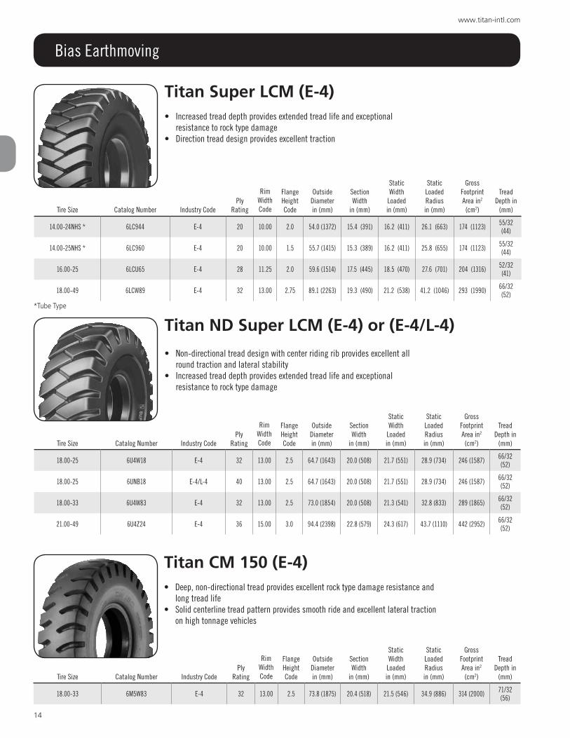
Bias Earthmoving
Earthmoving service TiresThe “E” series type tires are referred to as haulage tires in off-the-road earthmoving applications. These tires are designed to transport materials over unimproved surfaces at speeds under 40 mph and short distances, generally 2.5 miles one way.
E-1 rib design tires are normally used on free-rolling positions on quarry, mining and heavy road building equipment.E-2 traction design tires have open tread patterns designed to provide self loading scrapers with good traction in sand and soft,
loose materials. E-3 rock design tires are designed to offer good resistance to rock type damage plus good traction on cranes, hauling trucks and
scrapers. E-4 rock design tires feature tread depths that are 1.5 times deeper than the regular E-3 tread depth tires. This increased tread
mass gives extended tread life and exceptional resistance to rock type damage.E-7 flotation design tires are designed with a shallow rib tread allowing to run in soft, sandy soil. This tire is primarily used on
asphalt spreaders.
Titan lcM (E-3) or (E-3/l-3)• Compact tread design provides resistance to rock damage while still providing
excellent traction• Directional tread design provides excellent traction
Titan Nd lcM (E-3) or (E-3/l-3) Titan Mcs (E-3/l-3)• Non-directional tread design with center riding rib provides excellent all
round traction and lateral stability• Rock service tread design provides resistance to rock damage and long tread
life• MCS – is specifically designed for mobile crane service for use in rough
terrain applications
Tire Size Catalog Number Industry CodePly
Rating
Rim Width Code
Flange Height Code
Outside Diameter in (mm)
Section Width
in (mm)
Section Width
Loaded in (mm)
Static Loaded Radius in (mm)
Gross Footprint Area in2
(cm2)
Tread Depth
in (mm)
14.00-24NHS * 6CMR44 E-3 24 10.00 2.0 54.2 (1377) 15.4 (391) 16.1 (409) 25.3 (643) 180 (1161) 31/32 (24)
14.00-24NHS * 6CLU44 E-3/L-3 28 10.00 2.0 54.2 (1377) 15.4 (391) 16.1 (409) 25.3 (643) 180 (1161) 31/32 (24)
21.00-25 6CMZ22 E-3 36 15.00 3.0 69.1 (1755) 22.6 (599) 25.0 (635) 31.5 (800) 376 (2425) 43/32 (34)
Tire Size Catalog Number Industry CodePly
Rating
Rim Width Code
Flange Height Code
Outside Diameter in (mm)
Section Width
in (mm)
Section Width
Loaded in (mm)
Static Loaded Radius in (mm)
Gross Footprint Area in2
(cm2)
Tread Depth
in (mm)
15.5-25 6NN120 E-3/L-3 12 12.00 1.3 50.3 (1278) 15.5 (394) 17.3 (439) 22.8 (579) 205E (1323) 30/32 (24)
16.00-25 6NDU65 E-3 28 11.25 2.0 59.0 (1499) 17.5 (445) 18.8 (478) 26.8 (681) 204 (1316) 35/32 (28)
18.00-25 6NDW18 E-3 32 13.00 2.5 63.3 (1608) 20.3 (516) 21.3 (541) 29.1 (739) 238 (1536) 39/32 (31)
*Tube Type

11
800.USA.BEAR
Bias Earthmoving
Titan Nd lcM (E-3) or (E-3/l-3) & Titan Mcs (E-3/l-3) continued
Titan sl 100 (E-3) or (E-3/l-3)• Center riding rib provides a smooth ride and improved lateral stability• Non-directional tread design pattern provides excellent all round traction and
long wear
Tire Size Catalog Number Industry CodePly
Rating
Rim Width Code
Flange Height Code
Outside Diameter in (mm)
Section Width
in (mm)
Section Width
Loaded in (mm)
Static Loaded Radius in (mm)
Gross Footprint Area in2
(cm2)
Tread Depth
in (mm)
20.5-25 6NN521 E-3/L-3 16 17.00 2.0 58.9 (1496 21.7 (551) 23.4 (594) 25.5 (648) 315 (2032) 35/32 (28)
20.5-25 6NN921 E-3/L-3 20 17.00 2.0 58.9 (1496 21.7 (551) 23.4 (594) 25.5 (648) 315 (2032) 35/32 (28)
20.5-25 6NN921 E-3/L-3 20 17.00 2.0 58.9 (1496 21.7 (551) 23.4 (594) 25.5 (648) 315 (2032) 35/32 (28)
23.5-25 6NN923 E-3/L-3 20 19.50 2.5 62.0 (1575) 24.7 (627) 25.9 (658) 27.1 (688) 378 (2439) 39/32 (31)
26.5-25 6NN927 E-3/L-3 20 22.00 3.0 67.7 (1496) 27.9 (551) 29.9 (594) 28.3 (648) 466 (2032) 43/32 (34)
26.5-25 6NNT27 E-3/L-3 26 22.00 3.0 67.7 (1496) 27.9 (551) 29.9 (594) 28.3 (648) 466 (2032) 43/32 (34)
26.5-25 6NND27 E-3/L-3 44 22.00 3.0 67.7 (1496) 27.9 (551) 29.9 (594) 28.3 (648) 466 (2032) 43/32 (34)
29.5-25 6NNUW1 E-3/L-3 28 25.00 3.5 73.4 (1864) 30.5 (775) 32.0 (813) 31.8 (808) 571 (3684) 47/32 (37)
29.5-25 6NNXW1 E-3/L-3 34 25.00 3.5 73.4 (1864) 30.5 (775) 32.0 (813) 31.8 (808) 571 (3684) 47/32 (37)
29.5-29 6NDUW2 E-3 28 25.00 3.5 77.5 (1969) 30.3 (770) 31.7 (805) 34.3 (871) 535 (3452) 47/32 (37)
29.5-29 6NNXW2 E-3/L-3 34 25.00 3.5 77.5 (1969) 30.3 (770) 31.7 (805) 34.3 (871) 535 (3452) 47/32 (37)
29.5-35 6NDXW3 E-3 34 25.00 3.5 83. (2108) 30.2 (767) 31.7 (805) 37.7 (958) 472 (3045) 47/32 (37)
33.25-35 6NDAW5 E-3 38 27.00 3.5 88.6 (2250) 34.2 (869) 35.8 (909) 38.8 (986) 650 (4194) 53/32 (42)
33.25-35 6NNKW5 E-3/L-3 56 27.00 3.5 88.6 (2250) 34.2 (869) 35.8 (909) 38.8 (986) 650 (4194) 53/32 (42)
33.5-33 6NDDW6 E-3 44 28.00 4.0 86.9 (2207) 35.1 (892) 35.9 (912) 39.7 (1008) 708 (4568) 53/32 (28)
20.5-25 (MCS) 6MCR21 E-3/L-3 24 17.00 2.0 58.9 (1496) 21.7 (551) 23.4 (594) 25.5 (648) 315 (2031) 35/32 (28)
Tire Size Catalog Number Industry CodePly
Rating
Rim Width Code
Flange Height Code
Outside Diameter in (mm)
Section Width
in (mm)
Section Width
Loaded in (mm)
Static Loaded Radius in (mm)
Gross Footprint Area in2
(cm2)
Tread Depth
in (mm)
33.25-29 6SLWW4 E-3/L-3 32 26.0027.00 3.5 80.9 (2055) 34.5 (876) 36.3 (922) 35.8 (909) 644 (4155) 53/32
(42)
33.25-29 6SLAW4 E-3/L-3 38 26.0027.00 3.5 80.9 (2055) 34.5 (876) 36.3 (922) 35.8 (909) 644 (4155) 53/32
(42)
37.25-35 6SLZW7 E-3 36 29.00 3.5 94.5 (2400) 37.2 (945) 39.6 (1006) 42.0 (1067) 864 (5575) 58/32 (46)
Mcs

12
www.titan-intl.com
Bias Earthmoving
Titan MXl (E-3/l-3) • Aggressive tread for optimal traction• Sturdy tread elements for maximum torque transmission
Titan super rigger (E-3/l-3) • Non-directional wide tread • Long wearing tread compound for demanding material handling
operations
Titan super rigger lsW (E-3)
• LSW is a patented wheel and tire assembly designed to reduce vehicle bounce, reduce loping and improve lateral stability
• Features low aspect ratio tire and large wheel• Requires LSW wheel
Tire Size Catalog NumberIndustry
CodePly
RatingRim Width
Code
Flange Height Code
Outside Diameter in (mm)
Section Width
in (mm)
Static Width Loadedin (mm)
Static Loaded Radiusin (mm)
Gross Footprint Area in2 (cm2)
Tread Depth in (mm)
20.5-25 43B921 E-3/L-3 20 17.00 2.0 59.4 (1507) 21.8 (554) — 26.3 (668) 302 (1948) 48/32 (38.1)
Tire Size Catalog NumberIndustry
CodePly
RatingRim Width
Code
Flange Height Code
Outside Diameter in (mm)
Section Width
in (mm)
Static Width Loadedin (mm)
Static Loaded Radiusin (mm)
Gross Footprint Area in2 (cm2)
Tread Depth in (mm)
13.00-24TG 49L333 E-3/L-3 12 9.00GR — 50.8 (1290) 13.4 (340) — 23.3 (592) — 31/32 (25)
13.00-24TG 49L38A E-3/L-3 16 9.00GR — 50.8 (1290) 13.4 (340) — 23.3 (592) — 31/32 (25)
14.00-24TG 49L344 E-3/L-3 12 9.00GR — 53.7 (1364) 15.3 (389) — 23.8 (605) — 32/32 (25)
14.00-24TG 49L3R4 E-3/L-3 16 9.00GR — 53.7 (1364) 15.3 (389) — 23.8 (605) — 32/32 (25)
Tire Size Catalog NumberIndustry
CodePly
RatingRim Width
Code
Flange Height Code
Outside Diameter in (mm)
Section Width
in (mm)
Static Width Loadedin (mm)
Static Loaded Radiusin (mm)
Gross Footprint Area in2 (cm2)
Tread Depth in (mm)
LSW330-851 G9L333 E-3 12 10.00 — 51.5 (1308) 13.5 (343) — 23 (584) — 31/32 (25)

13
800.USA.BEAR
Bias Earthmoving
Titan cM100 (E-3)• Rock service tread designed for the challenges of large equipment demands• Solid centerline tread pattern provides excellent cut resistance, smooth ride and
extended wear
Titan Grizz 100 (E-3)• Rock service tread designed for the challenges of large equipment demands• Solid centerline tread pattern provides excellent cut resistance, smooth ride and
extended wear
Titan XG-3 (E-3)• All purpose design for traction and flotation• Solid centerline provides excellent lateral stability
Tire Size Catalog Number Industry CodePly
Rating
Rim Width Code
Flange Height Code
Outside Diameter in (mm)
Section Width
in (mm)
Static Width
Loadedin (mm)
Static Loaded Radiusin (mm)
Gross Footprint Area in2
(cm2)
Tread Depth in
(mm)
27.00-49 6M1F79 E-3 48 19.50 4.0 104.6 (2657) 29.7 (754) 32.0 (813) 47.9 (1217) 656 (4232) 53/32
(42)
37.5-39 6M1HW9 E-3 52 32.00 4.5 98.2 (2494) 38.9 (988) 41.0 (1041) 44.9 (1140) 795 (5129) 66/32 (52)
Tire Size Catalog Number Industry CodePly
Rating
Rim Width Code
Flange Height Code
Outside Diameter in (mm)
Section Width
in (mm)
Static Width
Loadedin (mm)
Static Loaded Radiusin (mm)
Gross Footprint Area in2
(cm2)
Tread Depth in
(mm)
30-56.5 6M1F50 E-3 48 22.00 15˚ 104.6 (2657)E 29.0 (737)E 31.3 (795)E 47.9E
(1217)E656E
(4232)E53/32 (42)
Tire Size Catalog Number Industry CodePly
Rating
Rim Width Code
Flange Height Code
Outside Diameter in (mm)
Section Width
in (mm)
Static Width
Loadedin (mm)
Static Loaded Radiusin (mm)
Gross Footprint Area in2
(cm2)
Tread Depth in
(mm)
37.25-35 6X3ZW7 E-3 36 29.00 3.5 94.6 (2403) 37.6 (955) 39.8 (1011) 41.9 (1064) 802 (5175) 58/32 (46)
14
www.titan-intl.com
Bias Earthmoving
Titan super lcM (E-4)• Increased tread depth provides extended tread life and exceptional
resistance to rock type damage• Direction tread design provides excellent traction
Titan Nd super lcM (E-4) or (E-4/l-4)
• Non-directional tread design with center riding rib provides excellent all round traction and lateral stability
• Increased tread depth provides extended tread life and exceptional resistance to rock type damage
Titan cM 150 (E-4)• Deep, non-directional tread provides excellent rock type damage resistance and
long tread life• Solid centerline tread pattern provides smooth ride and excellent lateral traction
on high tonnage vehicles
Tire Size Catalog Number Industry CodePly
Rating
Rim Width Code
Flange Height Code
Outside Diameter in (mm)
Section Width
in (mm)
Static Width
Loadedin (mm)
Static Loaded Radiusin (mm)
Gross Footprint Area in2
(cm2)
Tread Depth in
(mm)
14.00-24NHS * 6LC944 E-4 20 10.00 2.0 54.0 (1372) 15.4 (391) 16.2 (411) 26.1 (663) 174 (1123) 55/32 (44)
14.00-25NHS * 6LC960 E-4 20 10.00 1.5 55.7 (1415) 15.3 (389) 16.2 (411) 25.8 (655) 174 (1123) 55/32 (44)
16.00-25 6LCU65 E-4 28 11.25 2.0 59.6 (1514) 17.5 (445) 18.5 (470) 27.6 (701) 204 (1316) 52/32 (41)
18.00-49 6LCW89 E-4 32 13.00 2.75 89.1 (2263) 19.3 (490) 21.2 (538) 41.2 (1046) 293 (1990) 66/32 (52)
Tire Size Catalog Number Industry CodePly
Rating
Rim Width Code
Flange Height Code
Outside Diameter in (mm)
Section Width
in (mm)
Static Width
Loadedin (mm)
Static Loaded Radiusin (mm)
Gross Footprint Area in2
(cm2)
Tread Depth in
(mm)
18.00-25 6U4W18 E-4 32 13.00 2.5 64.7 (1643) 20.0 (508) 21.7 (551) 28.9 (734) 246 (1587) 66/32 (52)
18.00-25 6UNB18 E-4/L-4 40 13.00 2.5 64.7 (1643) 20.0 (508) 21.7 (551) 28.9 (734) 246 (1587) 66/32 (52)
18.00-33 6U4W83 E-4 32 13.00 2.5 73.0 (1854) 20.0 (508) 21.3 (541) 32.8 (833) 289 (1865) 66/32 (52)
21.00-49 6U4Z24 E-4 36 15.00 3.0 94.4 (2398) 22.8 (579) 24.3 (617) 43.7 (1110) 442 (2952) 66/32 (52)
Tire Size Catalog Number Industry CodePly
Rating
Rim Width Code
Flange Height Code
Outside Diameter in (mm)
Section Width
in (mm)
Static Width
Loadedin (mm)
Static Loaded Radiusin (mm)
Gross Footprint Area in2
(cm2)
Tread Depth in
(mm)
18.00-33 6M5W83 E-4 32 13.00 2.5 73.8 (1875) 20.4 (518) 21.5 (546) 34.9 (886) 314 (2000) 71/32 (56)
*Tube Type

15
800.USA.BEAR
Bias Earthmoving
Titan Quarry special cM 150 (E-4) or (E-4/l-4)• Special tread compound with excellent chip andcut resistance from shot rock• Tread designed for traction with deep lugs and center riding rib for smoother
ride
Tire Size Catalog Number Industry CodePly
Rating
Rim Width Code
Flange Height Code
Outside Diameter in (mm)
Section Width
in (mm)
Static Width
Loadedin (mm)
Static Loaded Radiusin (mm)
Gross Footprint Area in2
(cm2)
Tread Depth in
(mm)
21.00-35 6M5Z25 E-4 36 15.00 3.0 81.0 (2057) 23.5 (597) 24.8 (630) 37.4 (950) 400 (2581) 71/32 (56)
24.00-35 6M5C43 E-4 42 17.00 3.5 81.1 (2060) 23.6 (599) 27.8 (706) 39.6 (1005) 428 (2761) 70/32 (56)
24.00-35 6M5F43 E-4 48 17.00 3.5 81.1 (2060) 23.6 (599) 27.8 (706) 39.6 (1005) 428 (2761) 70/32 (56)
24.00-49 6M5F49 E-4 48 17.00 3.5 100.8 (2560) 26.5 (673) 28.0 (711) 46.9 (1191) 532 (3432) 70/32
(56)
27.00-49 6M5F79 E-4 48 19.50 4.0 106.5 (2705) 30.3 (769) 32.0 (812) 49.3 (1252) 683 (4407) 78/32
(62)
30.00-51 6M5H30 E-4 52 22.00 4.5 114.4 (2905) 32.5 (825) 34.8 (883) 52.7 (1399) 816 (5265) 85/32
(68)
33.00-51 6M5J35 E-4 58 24.00 5.0 119.1 (3025) 35.9 (912) 38.2 (970) 54.7 (1389) 1053 (6794) 98/32
(78)
33.25-35 6M5AW5 E-4 38 27.00 3.5 89.3 (2268) 34.2 (868) 36.6 (929) 39.8 (1011) 700 (4516) 78/32 (62)
33.25-35 6M5DW5 E-4 44 27.00 3.5 89.3 (2268) 34.2 (868) 36.6 (929) 39.8 (1011) 700 (4516) 78/32 (62)
37.25-35 6M5ZW7 E-4 36 31.00 3.5 94.3 (2395) 36.1 (916) 38.3 (972) 42.0 (1067) 905 (5839) 87/32 (69)
Tire Size Catalog Number Industry CodePly
Rating
Rim Width Code
Flange Height Code
Outside Diameter in (mm)
Section Width
in (mm)
Static Width
Loadedin (mm)
Static Loaded Radiusin (mm)
Gross Footprint Area in2
(cm2)
Tread Depth in
(mm)
18.00-33 6QSW83 E-4 32 13.00 2.5 73.8 (1875) 20.4 (518) 21.5 (546) 34.9 (886) 314 (2000) 71/32 (56)
21.00-35 6QSZ25 E-4 36 15.00 3.0 81.0 (2057) 23.5 (597) 24.8 (630) 37.4 (950) 400 (2581) 71/32 (56)
24.00-35 6QSC43 E-4 42 17.00 3.5 81.1 (2060) 23.6 (599) 27.8 (706) 39.6 (1005) 428 (2761) 70/32 (56)
24.00-35 6QSF43 E-4 48 17.00 3.5 81.1 (2060) 23.6 (599) 27.8 (706) 39.6 (1005) 428 (2761) 70/32 (56)
24.00-49 6QSF49 E-4 48 17.00 3.5 100.8 (2560) 26.5 (673) 28.0 (711) 39.6 (1005) 428 (2761) 70/32
(56)
27.00-49 6QSF79 E-4/L-4 48 19.50 4.0 106.5 (2705) 30.3 (769) 32.0 (812) 49.3 (1252) 683 (4407) 78/32
(62)
30.00-51 6QSH30 E-4 52 19.50 4.0 106.5 (2705) 30.3 (769) 32.0 (812) 49.3 (1252) 683 (4407) 78/32
(62)
33.00-51 6QSJ35 E-4 58 24.00 5.0 119.1 (3025) 35.9 (912) 38.2 (970) 54.7 (1389) 1053 (6794) 98/32 (78)

16
www.titan-intl.com
Bias Earthmoving
Titan super sand Flotation (E-7)• Rib design provides excellent steering stability and improved
lateral traction• Shallow tread depth provides excellent heat dissipation• Designed for paving applications
Tread A Tread B
Titan cH 150 (E-4/l-4) • Deep, non-directional tread provides excellent rock type damage resistance and
long tread life• Solid centerline tread pattern provides smooth ride and excellent lateral traction
Tire SizeTread Style Catalog Number Industry Code
Ply Rating
Rim Width Code
Flange Height Code
Outside Diameter in (mm)
Section Width
in (mm)
Static Width
Loadedin (mm)
Static Loaded Radiusin (mm)
Gross Footprint Area in2
(cm2)
Tread Depth in
(mm)
14.00-20DT A 6DT0D4 E-7 10 10.00W 1.8 47.8 (1219) 15.6 (384) 17.0 (432) 20.8 (503) 166 (1523) 12/32 (10)
14.00-20DT A SSF0D4 E-7 10 10.00W 1.8 47.8 (1219) 15.6 (384) 17.0 (432) 20.8 (503) 166 (1523) 12/32 (10)
16.00-24DT A 6DT1D6 E-7 12 10.00W 2.0 57.1 (1450) 18.7 (475) 20.5 (516) 24.4 (620) 393 (2536) 14/32 (11)
18.00-25DT B 6DT5D8 E-7 16 10.00 1.5 59.2 (1504) 19.8 (503) 23.1 (587) 24.2 (615) 306 (1974) 15/32 (12)
18.00-25DT B 6DT9D8 E-7 20 10.00 1.5 59.2 (1504) 19.8 (503) 23.1 (587) 24.2 (615) 306 (1974) 15/32 (12)
21.00-25DT B 6DTUK2 E-7 28 15.00 3.0 66.7 (1693) 23.1 (587) 24.9 (631) 28.5 (723) 423 (2729) 32/32 (25)
Tire Size Catalog Number Industry CodePly
Rating
Rim Width Code
Flange Height Code
Outside Diameter in (mm)
Section Width
in (mm)
Static Width
Loadedin (mm)
Static Loaded Radiusin (mm)
Gross Footprint Area in2
(cm2)
Tread Depth in
(mm)
18.00-25 6HLB18TTB E-4/L-4 40 13.00 2.5 61.5 (1654) 20.4 (518) 21.7 (551) 29.7 (754) — 66/32 (52)

17
800.USA.BEAR
Bias Grader Service
Grader service TiresThe “G” series type tires are used primarily on motor graders in all types of applications. These tires are designed for speeds up to 25 mph and unlimited distance. G-2 traction design tires have open tread patterns designed to provide good traction.
Titan Motor Grader Hd (l-2/G-2) • Proven performance tread design with massive lugs, large center overlap to resist buckling, tearing
and cracking• Very durable and resistant to punctures, features a heavy duty tubeless construction
Titan loader Grader/loader Grader iii (G-2) or (l-2/G-2)• Interlocking center lugs provide excellent steering stability in soft ground• Open shoulders provide excellent traction and self-cleaning
Tire Size Catalog Number Industry CodePly
RatingRim Width
Code
Flange Height Code
Outside Diameter in (mm)
Section Width
in (mm)
Static Width
Loadedin (mm)
Static Loaded Radiusin (mm)
Gross Footprint Area in2
(cm2)
Tread Depth in
(mm)
13.00-24TG LG3333 G-2 12 8.0TG — 51.0 (1295) 14.1 (358) 15.2 (386) 23.4 (594) 175 (1129) 29/32 (23)
14.00-24TG LG3344 G-2 12 8.0TG — 53.6 (1361) 14.4 (366) 16.1 (409) 24.0 (609) 190 (1226) 31/32 (25)
15.5-25 LG3120 L-2/G-2 12 12.00 1.3 50.0 (1270) 15.4 (394) 16.2 (413) 22.55 (573) 160 (1032) 30/32 (24)
16.00-24TG * 61G566 G-2 16 10.00VA – 58.7 (1490) 17.6 (447) 18.9 (480) 26.3 (668) 291 (1878) 33/32 (26)
17.5-25 LG3117 L-2/G-2 12 14.00 1.5 52.8 (1341) 17.25 (438) 18.3 (409) 23.6 (599) 203 (1290) 32/32 (25)
17.5-25 LG3517 L-2/G-2 16 14.00 1.5 52.8 (1341) 17.25 (438) 18.3 (409) 23.6 (599) 203 (1290) 32/32 (25)
17.5-25 LG3917 L-2/G-2 20 14.00 1.5 52.8 (1341) 17.25 (438) 18.3 (409) 23.6 (599) 203 (1290) 32/32 (25)
20.5-25 * 61L121 L-2 12 17.00 2.0 59.0 (1499) 21.1 (536) 22.7 (577) 27.8 (706) 387 (2496) 35/32 (28)
*Loader Grader
Tire Size Catalog Number Industry CodePly
RatingRim Width
Code
Flange Height Code
Outside Diameter in (mm)
Section Width
in (mm)
Static Width
Loadedin (mm)
Static Loaded Radiusin (mm)
Gross Footprint Area in2
(cm2)
Tread Depth in
(mm)
13.00-24TG 367333 L-2/G-2 12 8.00TG — 50.8 (1290) 13.8 (351) — 23.1 (587) — 29/32 (23)
13.00-24TG 36738A L-2/G-2 16 8.00TG — 50.8 (1290) 13.8 (351) — 23.1 (587) — 29/32 (23)
14.00-24TG 367344 L-2/G-2 12 10.00VA — 53.0 (1346) 15.1 (384) — 24.0 (610) — 31/32 (25)
14.00-24TG 3673R7 L-2/G-2 14 10.00VA — 53.0 (1346) 15.1 (384) — 24.0 (610) — 31/32 (25)

18
www.titan-intl.com
Bias Grader Service
Titan lsW G8l (G-2) • LSW G8L G-2 is a patented wheel and tire assembly designed to reduce vehicle bounce,
reduce loping and improve lateral stability• Features low aspect ratio tire and large wheel• Lower side wall• Requires LSW rims
Titan Hd 2000ii (G-2) • Deeper non-skid depth guards against punctures and premature wearouts• Six layer high tensile nylon construction creates one of the strongest tires in the industry• Massive rim guard reduces damage• Design ensures compatibility with steel
Titan super Grader (G-2/l-2) • Directional, open tread design is self cleaning, providing excellent traction
Tire Size Catalog Number Industry CodePly
Rating Rim CodeFlange Code
Outside Diameter in (mm)
Section Width
in (mm)
Section Width
Loaded in (mm)
Static Loaded Radius in (mm)
Gross Footprint Area in2
(cm2)
Tread Depth
in (mm)
16.00-24TG 3SG666 L-2/G-2 16 10.00VA — 58.8 (1494) 17.5 (445) — 26.1 (663) — 35/32 (28)
Tire Size Catalog Number Industry CodePly
Rating Rim Code
Inflation Pressure PSI (bar)
Max Load mph (kph)
Max Load lbs (kg)
Outside Diameter in (mm)
Section Width
in (mm)
Static Loaded Radius in (mm)
Tread Depth
in (mm)
LSW 330-851 G8L333 G-2 12 10.00 44 (305) 25 (40) 6,000 (2750) 50.5 (1283) 12.4 (315) 22.6 (574) 29/32
(23)
LSW 330-851 G8L38A G-2 16 10.00 54 (370) 25 (40) 7,150 (3245) 50.5 (1283) 12.4 (315) 22.6 (574) 29/32 (23)
LSW 360-851 G8L344 G-2 12 10.00 36 (250) 25 (40) 6,800 (3085) 52.9 (1344) 13.8 (351) 23.7 (602) 31/32
(25)
LSW 395-851 G8L120 G-2 12 317 36 (250) 25 (40) 5,840 (2650) 50.3 (1278) 15.5 (394) 22.7 (577) 29/32
(23)
Tire SizeCatalog Number
Industry Code
Ply Rating Rim Code
Inflation Pressure PSI (bar)
Max Load mph (kph)
Max Load lbs (kg)
Outside Diameter in (mm)
Section Width
in (mm)
Static Loaded Radius in (mm)
Tread Depth in (mm)
13.00-24TG 49E333 G-2 12 9.00GR 44 (3.1) 25 (40) 6,000 (2750) 50.6 (1285) 13.8 (351) 23 (584) 32/32 (25)
13.00-24TG 49E38A G-2 16 9.00GR 54 (3.7) 25 (40) 7,150 (3245) 50.6 (1285) 13.8 (351) 23 (584) 32/32 (25)
14.00-24TG 49E344 G-2 12 9.00GR 36 (2.5) 25 (40) 6,800 (3085) 52.4 (1331) 14.9 (378) 24.5 (622) 38/32 (30)

19
800.USA.BEAR
Bias Loader - Dozer Service
loader - dozer service TiresThe “L” series type tires are used on all size loaders and dozers in off-the-road applications. Most loader type tires, because of their extremely heavy construction, are limited to very low speeds, less than 5 mph, and very short distances, less than 250 feet.
L-2 traction design tires have open tread patterns designed to provide good traction in sand and soft, loose materials.L-3 rock design tires are designed to offer good resistance to rock type damage plus good traction in general purpose loader
operations.L-4 rock design tires feature tread depths that are 1.5 times deeper than the regular L-3 tread depth tires. This increased tread
mass gives extended tread life and exceptional resistance to rock type damage.L-5 rock design tires feature tread depths that are 2.5 times deeper than the regular L-3 tread depth tires. This extremely heavy
tread mass offers improved rock resistance and extended tread life in severe rock conditions.L-5S solid design tires offer a massive tread for the ultimate in resisting rock damage and penetration. This tire is perfect for those
applications where shoulder lug tearing has been a problem in the past or where protective chains are required.L-5/L-5S is unique in that it offers both rock design pattern along with a smooth tread design. This design with the smooth design
mounted on the outboard side of the loader provides exceptional tearing and cut resistance while providing additional traction.
Titan loader dozer ii (l-2)• Exceptional performance rating and heavy duty ply ratings• Laterally designed lugs provide maximum, even traction along the length of the lug• Lugs resist buckling, cracking and tearing
Titan lift rigger ii (l-2)• Combines thicker, self-cleaning lugs in a directional pattern with a low aspect ratio• Greater lateral stability and flotation than conventional aerial lift tires
Tire Size Catalog Number Industry CodePly
RatingRim Code
Flange Code
Outside Diameter in (mm)
Section Width in (mm)
Section Width
Loaded
Static Loaded Radius in (mm)
Gross Footprint Area in2
(cm2)Tread Depth
in (mm)
15.5-25 431120 L-2 12 12.00 1.3 49.9 (1267) 15.8 (401) — 22.5 (572) — 29/32 (23)
17.5-25 431117 L-2 12 14.00 1.5 51.7 (1313) 18.6 (472) — 23.2 (589) — 32/32 (25)
17.5-25 431517 L-2 16 14.00 1.5 51.7 (1313) 18.6 (472) — 23.2 (589) — 32/32 (25)
20.5-25 431121 L-2 12 17.00 2.0 56.3 (1430) 21.7 (551) — 25 (635) — 36/32 (29)
20.5-25 431521 L-2 16 17.00 2.0 56.3 (1430) 21.7 (551) — 25 (635) — 36/32 (29)
20.5-25 431921 L-2 20 17.00 2.0 56.3 (1430) 21.7 (551) — 25 (635) — 36/32 (29)
23.5-25 431123 L-2 12 19.50 2.5 63.5 (1613) 23.6 (599) — 28.5 (724) — 38/32 (30)
23.5-25 431523 L-2 16 19.50 2.5 63.5 (1613) 23.6 (599) — 28.5 (724) — 38/32 (30)
23.5-25 431923 L-2 20 19.50 2.5 63.5 (1613) 23.6 (599) — 28.5 (724) — 38/32 (30)
Tire Size Catalog Number Industry Code
Load/Spped Index Rim Code
Inflation Pressure PSI (bar)
Max Load mph (kph)
Max Load lbs (kg)
Outside Diameter in (mm)
Section Width
in (mm)
Static Loaded Radius in (mm)
Tread Depth
in (mm)
400/70-20 43C34L L-2 150 A8/B 14.00 61 (420) 25 (40) 7,150 (3245) 42.9 (1090) 15.9 (404) 19.3 (490) 33/32 (26)
LSW 400-648 G3C34L L-2 149 A8/B 356 58 (400) 25 (40) 7,150 (3245) 42.9 (1090) 15.7 (399) 19.3 (490) 33/32 (26)

20
www.titan-intl.com
Bias Loader - Dozer Service
Titan Nd lcM (l-3) or (l-3/E-3) Titan Mcs lcM (l-3/E-3)• Non-directional tread design with center riding rib provides excellent all round
traction and lateral stability• Rock service tread design provides resistance to rock damage and long tread life• MCS – is specifically designed for mobile crane service for use in rough terrain
applications
Titan super rigger (l-3/E-3) • Non-directional wide tread • Long wearing tread compound for demanding material handling
operations
Tire Size Catalog Number Industry CodePly
RatingRim Code
Flange Code
Outside Diameter in (mm)
Section Width
in (mm)
Section Width
Loaded in (mm)
Static Loaded Radius in (mm)
Gross Footprint Area in2
(cm2)
Tread Depth
in (mm)
15.5-25 6NN120 E-3/L-3 12 12.00 1.3 50.3 (1278) 15.5 (394) 17.3 (439) 22.8 (579) 205E (1323) 30/32 (24)
16.00-25 6N3W65 L-3 32 11.25 2.0 59.0 (1499) 17.5 (445) 18.8 (478) 26.8 (681) 204 (1316) 35/32 (28)
17.5-25 6N3117 L-3 12 14.00 1.5 53.7 (1364) 17.5 (445) 19.2 (488) 23.5 (597) 264 (1703) 30/32 (24)
17.5-25 6N3R17 L-3 24 14.00 1.5 53.7 (1364) 17.5 (445) 19.2 (488) 23.5 (597) 264 (1703) 30/32 (24)
20.5-25 6NN521 L-3/E-3 16 17.00 2.0 59.3 (1506) 20.9 (531) 21.9 (556) 26.5 (673) 315 (2032) 35/32 (28)
20.5-25 6NN921 L-3/E-3 20 17.00 2.0 59.3 (1506) 20.9 (531) 21.9 (556) 26.5 (673) 315 (2032) 35/32 (28)
20.5-25 6NN921 L-3/E-3 20 17.00 2.0 59.3 (1506) 20.9 (531) 21.9 (556) 26.5 (673) 315 (2032) 35/32 (28)
23.5-25 6NN923 L-3/E-3 20 19.50 2.5 62.9 (1598) 25.0 (635) 25.5 (648) 27.6 (701) 378 (2439) 39/32 (31)
26.5-25 6NN927 L-3/E-3 20 22.00 3.0 67.7 (2634) 27.8 (706) 29.4 (747) 28.9 (734) 490 (3161) 43/32 (34)
26.5-25 6NNT27 L-3/E-3 26 22.00 3.0 67.7 (2634) 27.8 (706) 29.4 (747) 28.9 (734) 490 (3161) 43/32 (34)
26.5-25 6NND27 L-3/E-3 44 22.00 3.0 67.7 (2634) 27.8 (706) 29.4 (747) 28.9 (734) 490 (3161) 43/32 (34)
29.5-25 6NNUW1 L-3/E-3 28 25.00 3.0 74.1 (1877) 31.0 (787) 33.4 (848) 31.5 (800) 648 (4181) 47/32 (37)
29.5-25 6NNXW1 L-3/E-3 34 25.00 3.0 74.1 (1877) 31.0 (787) 33.4 (848) 31.5 (800) 648 (4181) 47/32 (37)
29.5-29 6NNXW2 L-3/E-3 34 25.00 3.5 73.4 (1864) 30.5 (775) 32.0 (813) 31.8 (808) 571 (3684) 47/32 (37)
33.25-35 6NNKW5 L-3/E-3 56 27.00 3.5 88.6 (2250) 34.2 (869) 35.8 (909) 38.8 (986) 650 (4194) 53/32 (42)
20.5-25 6MCR21 L-3/E-3 24 17.00 2.0 58.9 (1496) 21.7 (551) 23.4 (594) 25.5 (648) 315 (2031) 35/32 (28)
Tire Size Catalog Number Industry CodePly
RatingRim Code
Flange Code
Outside Diameter in (mm)
Section Width in (mm)
Section Width
Loaded
Static Loaded Radius in (mm)
Gross Footprint Area in2
(cm2)Tread Depth
in (mm)
13.00-24TG 49L333 L-3/E-3 12 9.00GR — 50.8 (1290) 13.4 (340) — 23.3 (592) — 31/32 (25)
13.00-24TG 49L38A L-3/E-3 16 9.00GR — 50.8 (1290) 13.4 (340) — 23.3 (592) — 31/32 (25)
14.00-24TG 49L344 L-3/E-3 12 9.00GR — 53.7 (1364) 15.3 (389) — 23.8 (605) — 32/32 (25)
14.00-24TG 49L3R4 L-3/E-3 16 9.00GR — 53.7 (1364) 15.3 (389) — 23.8 (605) — 32/32 (25)
Mcs

21
800.USA.BEAR
Bias Loader - Dozer Service
Titan ld 100 (l-3)• Solid centerline tread pattern provides excellent cut resistance, smooth ride and
extended wear• Non-directional tread design pattern provides excellent all round traction and
long wear
Titan sl 100 (E-3/l-3)• Center riding rib provides a smooth ride and improved lateral stability• Non-directional tread design pattern provides excellent all round traction and
long wear
Titan MXl (E-3/l-3) • Multiple nylon body ply construction for improved penetration resistance• Large contact area for improved treadwear• Lug design offers increased biting edges
Tire Size Catalog Number Industry CodePly
RatingRim Code
Flange Code
Outside Diameter in (mm)
Section Width
in (mm)
Section Width
Loaded in (mm)
Static Loaded Radius in (mm)
Gross Footprint Area in2
(cm2)
Tread Depth
in (mm)
20.5-25 6D1921 L-3 20 17.00 2.0 58.7 (1491) 21.6 (549) 23.3 (592) 25.8 (655) 345 (2225) 40/32 (32)
23.5-25 6D1923 L-3 20 19.50 2.5 62.9 (1598) 25.5 (648) 26.7 (678) 27.6 (701) 399 (2574) 43/32 (34)
26.5-25 6D1927 L-3 20 22.00 3.0 67.9 (1725) 28.7 (729) 30.6 (777) 29.7 (754) 513 (3310) 49/32 (39)
29.5-25 6D1UW1 L-3 28 25.00 3.5 73.7 (1872) 31.1 (790) 33.5 (851) 31.9 (810) 633 (4084) 56/32 (45)
29.5-25 6D1XW1 L-3 34 25.00 3.5 73.7 (1872) 31.1 (790) 33.5 (851) 31.9 (810) 633 (4084) 56/32 (45)
Tire Size Catalog Number Industry CodePly
RatingRim Code
Flange Code
Outside Diameter in (mm)
Section Width
in (mm)
Section Width
Loaded in (mm)
Static Loaded Radius in (mm)
Gross Footprint Area in2
(cm2)
Tread Depth
in (mm)
33.25-29 6SLWW4 E-3/L-3 32 27.00 3.5 80.9 (2055) 34.5 (876) 36.3 (922) 35.8 (909) 644 (4155) 53/32 (42)
33.25-29 6SLAW4 E-3/L-3 38 27.00 3.5 80.9 (2055) 34.5 (876) 36.3 (922) 35.8 (909) 644 (4155) 53/32 (42)
Tire Size Catalog Number Industry CodePly
RatingRim Code
Flange Code
Outside Diameter in (mm)
Section Width
in (mm)
Section Width
Loaded in (mm)
Static Loaded Radius in (mm)
Gross Footprint Area in2
(cm2)Tread Depth
in (mm)
20.5-25 43B921 E-3/L-3 20 17.00 2.0 59.4 (1507) 21.8 (554) — 26.3 (668) 302 (1948) 48/32 (38.1)

22
www.titan-intl.com
Bias Loader - Dozer Service
Titan super lcM (l-4)• Deep tread depth and interlocking tread pattern provide long tread life plus
exceptional traction
Titan cH 150 (l-4/E-4) • Deep, non-directional tread provides excellent rock type damage resistance and long tread life• Solid centerline tread pattern provides smooth ride and excellent lateral traction
Titan ld 150 (l-4)• Deep tread provides excellent rock type damage resistance and long tread life• Non-directional, solid centerline tread pattern provides excellent cut resistance,
smooth ride and extended wear
Tire Size Catalog Number Industry CodePly
RatingRim Code
Flange Code
Outside Diameter in (mm)
Section Width
in (mm)
Section Width
Loaded in (mm)
Static Loaded Radius in (mm)
Gross Footprint Area in2
(cm2)
Tread Depth
in (mm)
16.00-25 6L4W65TTB L-4 32 11.25 2.0 59.6 (1514) 17.5 (445) 18.5 (470) 27.6 (701) 204 (1316) 52/32 (41)
Tire Size Catalog Number Industry CodePly
RatingRim Code
Flange Code
Outside Diameter in (mm)
Section Width
in (mm)
Section Width
Loaded in (mm)
Static Loaded Radius in (mm)
Gross Footprint Area in2
(cm2)
Tread Depth
in (mm)
18.00-25 6HLB18 L-4/E-4 40 13.00 2.5 61.5 (1654) 20.4 (518) 21.7 (551) 29.7 (754) --- 66/32 (52)
Tire Size Catalog Number Industry CodePly
RatingRim Code
Flange Code
Outside Diameter in (mm)
Section Width
in (mm)
Section Width
Loaded in (mm)
Static Loaded Radius in (mm)
Gross Footprint Area in2
(cm2)
Tread Depth
in (mm)
23.5-25 6DE923 L-4 20 19.50 2.5 67.1 (1704) 25.1 (638) 26.8 (681) 30.1 (765) 449 (2896) 66/32 (52)
23.5-25 6DER23 L-4 24 19.50 2.5 67.1 (1704) 25.1 (638) 26.8 (681) 30.1 (765) 449 (2896) 66/32 (52)
26.5-25 6DET27 L-4 26 22.00 3.0 70.7 (1796) 27.6 (701) 29.6 (752) 31.5 (800) 539 (3477) 66/32 (52)
29.5-25 6DEUW1 L-4 28 25.00 3.5 75.5 (1918) 30.2 (767) 32.9 (836) 33.0 (838) 539 (3864) 70/32 (56)
29.5-29 6DEUW2 L-4 28 25.00 3.5 78.8 (2002) 30.2 (767) 32.9 (836) 33.0 (838) 539 (3864) 70/32 (56)
35/65-33* 6DLC6B L-4 42 28.00 3.5 81.5 (2070) 35.1 (891) 36.8 (935) 36.6 (930) 658 (4244) 70/32 (56)
* (7x7 Belted)

23
800.USA.BEAR
Bias Loader - Dozer Service
Titan cM 150 (l-4)• Deep tread depth, center running rib and massive lugs provide long tread life
and low cost per hour with excellent traction
Titan ls 150• Open, deep tread pattern provides excellent traction in extreme conditions• Tread compound designed for increased resistance to tread chunking and tearing• Steel belted construction provides excellent penetration resistance
Titan ld 250 (l-5) crB Titan ld 250 Belted (l-5) 7x7 • Extra deep tread provides excellent rock type damage resistance
and long tread life• Open non-directional tread pattern provides all round traction
with excellent self-cleaning• CRB - Features Aralon Cut Resistant Breaker construction, which
provides increased strength and durability without sacrificing heat resistance
• Belted 7x7 - Features 7x7 steel belted construction, which provides increased cut resistance and extended wear
Titan LD 250 CRB Titan LD 250 Belted 7x7
Tire Size Catalog Number Industry CodePly
RatingRim Code
Flange Code
Outside Diameter in (mm)
Section Width
in (mm)
Section Width
Loaded in (mm)
Static Loaded Radius in (mm)
Gross Footprint Area in2
(cm2)
Tread Depth
in (mm)
21.00-35 6MLC25 L-4 42 15.00 3.0 81.0 (2057) 23.5 (597) 24.8 (630) 37.4 (950) 400 (2581) 71/32 (56)
Tire Size Catalog Number Industry CodePly
RatingRim Code
Flange Code
Outside Diameter in (mm)
Section Width
in (mm)
Section Width
Loaded in (mm)
Static Loaded Radius in (mm)
Gross Footprint Area in2
(cm2)
Tread Depth
in (mm)
725/70-25 LT45M6 L-4 16 22.00 3.0 65.8 (1672) 26.9 (684) 29.2 (742) 27.8 (707) 608 (3923) 72/32 (57)
Tire Size Catalog Number Industry CodePly
RatingRim Code
Flange Code
Outside Diameter in (mm)
Section Width
in (mm)
Section Width
Loaded in (mm)
Static Loaded Radius in (mm)
Gross Footprint Area in2
(cm2)Tread Depth
in (mm)
20.5-25 6DA921 L-5 20 17.00 2.0 61.3 (1557) 21.4 (544) 23.1 (587) 27.7 (704) 294 (1897) 89/32 (71)
23.5-25 6DA923 L-5 20 19.50 2.5 66.4 (1686) 24.9 (632) 26.5 (673) 29.6 (752) 400 (2580) 95/32 (75)
26.5-25 6DAT27 L-5 26 22.00 3.0 71.5 (1816) 28.1 (714) 29.7 (754) 31.9 (810) 490 (3161) 105/32 (83)
29.5-25 6DAUW1 L-5 28 25.00 3.5 75.1 (1908) 30.1 (765) 32.3 (820) 32.9 (836) 673 (4341) 128/32 (102)
29.5-29 6DAUW2 L-5 28 25.00 3.5 79.1 (2009) 30.0 (762) 31.8 (808) 35.5 (902) 669 (4315) 115/32 (91)
37.25-35 6DACW7 L-5 42 31.00 4.0 96.6 (2454) 37.5 (953) 39.9 (1013) 43.7 (1110) 961 (6200) 141/32 (112)
35/65-33 6DBC6B L-5 42 28.00 3.5 81.2 (2085) 33.9 (861) 35.3 (897) 36.8 (935) 722 (4657) 115/32 (91)
40/65-39 6DBV6C L-5 30 32.00 4.0 93.8 (2383) 39.8 (1011) 41.1 (1044) 42.1 (1069) 963 (6213) 128/32 (102)
45/65-45 6DBJ7E L-5 58 36.00 4.5 106.9 (2715) 42.4 (1077) 44.9 (1140) 48.1 (1222) 1193 (7695) 140/32 (111)
41.25/70-39 6DBC6D L-5 42 32.00 4.5 99.1 (2207) 40.2 (1021) 42.7 (1085) 45.2 (1148) 1041 (7614) 140/32 (111)
crB
Belted

24
www.titan-intl.com
Bias Loader - Dozer Service
Titan ld 250 super smooth (l-5s) crBTitan ld 250 super smooth (l-5s) caB Titan ld 250 super smooth Belted (l-5s) 7x7 • Extra deep tread depth provides long tread life in extreme conditions• Smooth tread design provides the maximum rock type damage resistance• CRB - Features Aralon Cut Resistant Breaker construction, which provides increased strength and
durability without sacrificing heat resistance• CAB - Features Cushion Armor Breaker steel belted construction, which gives increased cut resistance• Belted 7x7 - Features 7x7 steel belted construction, which provides increased cut resistance and
extended wear
Titan LD 250 CRB Titan LD 250 Belted 7x7
Tire Size Catalog Number Industry CodePly
RatingRim Code
Flange Code
Outside Diameter in (mm)
Section Width
in (mm)
Section Width
Loaded in (mm)
Static Loaded Radius in (mm)
Gross Footprint Area in2
(cm2)Tread Depth
in (mm)
29.5-29 6HAUW2 L-5/L-5S 28 25.00 3.5 78.9 (2004) 30.2 (767) 32.2 (818) 35.0 (889) 608 (3293) 115/32 (91)
35/65-33 6HBC6B L-5/L-5S 42 28.00 3.5 81.9 (2080) 34.6 (879) 36.1 (916) 36.6 (930) 715 (4611) 115/32 (91)
45/65-45 6HBJ7E L-5/L-5S 58 36.00 4.5 107.8 (2738) 42.7 (1085) 44.3 (1125) 48.5 (1232) 1325 (8546) 142/32 (113)
Tire Size Catalog Number Industry CodePly
RatingRim Code
Flange Code
Outside Diameter in (mm)
Section Width
in (mm)
Section Width
Loaded in (mm)
Static Loaded Radius in (mm)
Gross Footprint Area in2
(cm2)Tread Depth
in (mm)
20.5-25 6WA921 L-5/L-5S 20 17.00 2.0 61.3 (1557) 21.4 (544) 23.1 (587) 27.7 (704) 260 (1678) 86/32 (68)23.5-25 6WAR23 L-5/L-5S 24 19.50 2.5 66.2 (1681) 24.5 (632) 26.5 (673) 29.8 (757) 354 (2284) 95/32 (75)26.5-25 6WAW27 L-5/L-5S 32 22.00 3.0 70.9 (1801) 28.0 (711) 29.2 (742) 32.4 (823) 329 (2123) 105/32 (83)29.5-29 6WAXW2 L-5/L-5S 34 25.00 3.5 79.3 (2014) 30.2 (767) 32.2 (818) 35.0 (889) 608 (3923) 115/32 (91)29.5-25 6WAUW1 L-5/L-5S 28 25.00 3.5 75.1 (1908) 30.0 (702) 31.9 (810) 33.5 (851) 575 (3710) 128/32 (102)
29.5-25 6WAXW1 L-5/L-5S 34 25.00 3.5 75.1 (1908) 30.0 (702) 31.9 (810) 33.5 (851) 575 (3710) 128/32 (102)
35/65-33 6SBC6B L-5/L-5S 42 28.00 3.5 82.5 (2096) 35.7 (907) 37.5 (953) 36.7 (932) 755 (4871) 115/32 (91)
40/65-39 6SBV6C L-5/L-5S 30 32.00 4.0 93.8 (2383) 39.8 (1011) 41.1 (1044) 42.1 (1069) 963 (6213) 128/32 (102)
41.25/70-39 6SBC6D L-5/L-5S 42 32.00 4.5 99.3 (2522) 41.6 (1057) 43.5 (1105) 45.2 (1148) 1100 (7097) 140/32 (111)
45/65-45 6SBJ7E L-5/L-5S 58 36.00 4.5 108.8 (2764) 44.0 (1118) 46.2 (1173) 48.7 (1237) 1397 (9013) 142/32 (113)
Titan ld 250 Haf-Trac (l-5/l-5s) crBTitan ld 250 Haf-Trac Belted (l-5/l-5s) 7x7• Extra deep tread depth provides long tread life in extreme conditions• Smooth tread used on the outside provides excellent rock type
damage resistance, while the pattern on the inside provides increased traction
• CRB - Features Aralon Cut Resistant Breaker construction, which provides increased strength and durability without sacrificing heat resistance
• Belted 7x7 - Features 7x7 steel belted construction, which provides increased cut resistance and extended wear
crB
Belted
crB
caB
Belted

25
800.USA.BEAR
Bias Container Handling
container Handling TiresBias-ply container handling tires are designed with high ply rating construction featuring an enlarged bead for increased stability in heavy service. Optional compound choices include: “Value Engineered” VE610 tread designed for long wear on concrete and asphalt, or “General Purpose” for all applications where the surface is not improved.
Titan lcM (l-3)• Compact tread design provides excellent tread wear• Directional tread design provides excellent traction
Titan Nd lcM (l-3)• Non-directional tread design with center riding rib provides excellent traction
and stability• Rock service tread design provides long tread life
Tire Size Catalog Number Industry CodePly
Rating Rim CodeFlange Code
Outside Diameter in (mm)
Section Width
in (mm)
Section Width
Loaded in (mm)
Static Loaded Radius in (mm)
Gross Footprint Area in2
(cm2)
Tread Depth
in (mm)
VE610
14.00-24NHS 6C1U44 L-3 28 10.00W --- 54.2 (1377) 15.4 (391) 16.1 (409) 25.3 (643) 180 (1161) 31/32 (25)
21.00-25 6C1B22 L-3 40 15.00 3.0 70.7 (1796) 23.6 (599) 25.4 (645) 31.1 (790) 467 (3013) 43/32 (34)
GEnEral purposE
14.00-24NHS 6CLU44 L-3 28 10.00W --- 54.2 (1377) 15.4 (391) 16.1 (409) 25.3 (643) 180 (1161) 31/32 (25)
Tire Size Catalog Number Industry CodePly
RatingRim Code
Flange Code
Outside Diameter in (mm)
Section Width
in (mm)
Section Width
Loaded in (mm)
Static Loaded Radius in (mm)
Gross Footprint Area in2
(cm2)
Tread Depth
in (mm)
VE610
16.00-25 6N6W65 L-3 32 11.25 2.0 59 (1499) 17.5 (445) 18.8 (478) 26.8 (681) 204 (1316) 35/32 (28)
GEnEral purposE
16.00-25 6N3W65 L-3 32 11.25 2.0 59 (1499) 17.5 (445) 18.8 (478) 26.8 (681) 204 (1316) 35/32 (28)

26
www.titan-intl.com
Titan cH 150 (l-4) or (l-4/E-4)• Deep, non-directional tread provides excellent damage resistance and long tread life• Solid centerline tread pattern provides smooth ride and excellent lateral traction
Bias Container Handling
Titan super lcM (l-4)• Deep tread depth provides extended tread life• Interlocking directional tread pattern provides excellent traction
Titan cM 150 (l-4)• Deep, non-directional tread provides excellent rock type damage resistance and long tread life• Solid centerline tread pattern provides smooth ride and excellent lateral traction
Tire Size Catalog Number Industry CodePly
RatingRim Code
Flange Code
Outside Diameter in (mm)
Section Width
in (mm)
Section Width
Loaded in (mm)
Static Loaded Radius in (mm)
Gross Footprint Area in2
(cm2)
Tread Depth
in (mm)
VE610
18.00-25 6H6B18 L-4 40 13.00 2.5 61.5 (1654) 20.4 (518) 21.7 (551) 29.7 (754) --- 66/32 (52)
GEnEral purposE
18.00-25 6HLB18 L-4/E-4 40 13.00 2.5 61.5 (1654) 20.4 (518) 21.7 (551) 29.7 (754) --- 66/32 (52)
Tire Size Catalog Number Industry CodePly
Rating Rim CodeFlange Code
Outside Diameter in (mm)
Section Width
in (mm)
Section Width
Loaded in (mm)
Static Loaded Radius in (mm)
Gross Footprint Area in2
(cm2)
Tread Depth
in (mm)
VE610
14.00-24NHS 6U6R44 L-4 24 10.00W --- 54 (1372) 15.4 (391) 16.2 (411) 26.1 (663) 174 (1123) 55/32 (44)
16.00-25 6U6W65 L-4 32 11.25 2.0 59.6 (1514) 17.5 (445) 18.5 (470) 27.6 (701) 204 (1316) 52/32 (41)
GEnEral purposE
16.00-25 6L4W65 L-4 32 11.25 2.0 59.6 (1514) 17.5 (445) 18.5 (470) 27.6 (701) 204 (1316) 52/32 (41)
Tire Size Catalog Number Industry CodePly
RatingRim Code
Flange Code
Outside Diameter in (mm)
Section Width
in (mm)
Section Width
Loaded in (mm)
Static Loaded Radius in (mm)
Gross Footprint Area in2
(cm2)
Tread Depth
in (mm)
VE610
18.00-33 6M6B83 L-4 40 13.00 2.5 73.8 (1875) 20.4 (518) 21.5 (546) 34.9 (886) 314 (2026) 71/32 (56)

27
800.USA.BEAR
Titan super smooth (l-4s)• Deep tread depth provides extended tread life• Smooth tread design provides maximum damage resistance
Bias Container Handling
Titan cM 150 (l-4) continued
Titan super smooth (l-5s)• Extra deep tread depth provides long tread life• Smooth tread design provides the maximum damage resistance
Tire Size Catalog Number Industry CodePly
RatingRim Code
Flange Code
Outside Diameter in (mm)
Section Width
in (mm)
Section Width
Loaded in (mm)
Static Loaded Radius in (mm)
Gross Footprint Area in2
(cm2)
Tread Depth
in (mm)
21.00-35 6M6Z25 L-4 36 15.00 3.0 81.0 (2057) 23.5 (597) 24.8 (630) 37.4 (950) 400 (2581) 71/32 (56)
GEnEral purposE
18.00-33 6M5B83 E-4/L-4 40 13.00 2.5 73.8 (1875) 20.4 (518) 21.5 (546) 34.9 (886) 314 (2026) 71/32 (56)
21.00-35 6MLC25 L-4 42 15.00 3.0 81.0 (2057) 23.5 (597) 24.8 (630) 37.4 (950) 400 (2581) 71/32 (56)
Tire Size Catalog Number Industry CodePly
RatingRim Code
Flange Code
Outside Diameter in (mm)
Section Width
in (mm)
Section Width
Loaded in (mm)
Static Loaded Radius in (mm)
Gross Footprint Area in2
(cm2)
Tread Depth
in (mm)
VE610
18.00-25 646B18 L-4S 40 13.00 2.5 65.7 (1669) 19.8 (503) 21.66 (549) 29.6 (752) 282 (1819) 66/32 (52)
18.00-33 646B83 L-4S 40 13.00 2.5 73.8 (1875) 20.5 (521) 21.6 (549) 34.9 (886) 314 (2026) 66/32 (52)
GEnEral purposE
18.00-25 64SB18 L-4S 40 13.00 2.5 65.7 (1669) 19.8 (503) 21.66 (549) 29.6 (752) 282 (1819) 66/32 (52)
Tire Size Catalog Number Industry CodePly
RatingRim Code
Flange Code
Outside Diameter in (mm)
Section Width
in (mm)
Section Width
Loaded in (mm)
Static Loaded Radius in (mm)
Gross Footprint Area in2
(cm2)
Tread Depth
in (mm)
VE610
18.00-25 656B18 L-5S 40 13.00 2.5 65.7 (1669) 19.8 (503) 21.5 (546) 29.7 (755) 275 (1774) 99/32 (79)
GEnEral purposE
18.00-25 65SB18 L-5S 40 13.00 2.5 65.7 (1669) 19.8 (503) 21.5 (546) 29.7 (755) 275 (1774) 99/32 (79)

28
www.titan-intl.com
Bias Underground Mine / Material Handling
Titan ld 250 super smooth UGM (l-5s)• Super smooth tread pattern gives the maximum rock type damage resistance• New underground mine compound
Titan industrial deep Traction • For extra heavy-duty applications requiring a narrow tire option for mining use• Designed to withstand long, extended runs, this tire is easily one of the best tires for
performance and durability• Its unique broken bar/solid bar lug design provides increased footprint for better
braking, handling and load distribution
Tire Size Catalog Number Industry CodePly
Rating Rim CodeFlange Code
Outside Diameter in (mm)
Section Width
in (mm)
Section Width
Loaded in (mm)
Static Loaded Radius in (mm)
Gross Footprint Area in2
(cm2)
Tread Depth
in (mm)
12.00-24NHS SBT912 L-5S 20 8.50 --- 48.3 (1227) 12.5 (318) 14.0E (356) 21.8 (554) --- 46/32 (37)
14.00-24NHS SBT914 L-5S 20 10.00 W --- 54.1 (1373) 15.6 (396) --- 24.9 (632) 198 (5029) 102/32 (81)
17.5-25 SBT917 L-5S 20 14.00 1.5 55.2E (1402) 18.0E (457) 20.7E (526) 24.6E (625) --- 104/32
(83)
17.5-25 SBTR17 L-5S 24 14.00 1.5 55.2E (1402) 18.0E (457) 20.7E (526) 24.6E (625) --- 104/32
(83)
18.00-25 UGMW18 L-5S 32 13.00 2.5 65.7 (1669) 19.8 (503) 21.5 (546) 29.7 (755) 275 (1774) 99/32 (79)
20.5-25 6SU921 L-5S 20 17.00 2.0 61.3 (1557) 21.3 (544) 23.1 (587) 27.7 (704) 260 (1678) 86/32 (68)
23.5-25 6sUR23 L-5S 24 19.50 2.5 66.2 (1681) 24.5 (632) 26.5 (673) 29.8 (757) 354 (2284) 95/32 (75)
26.5-25 6SUW27 L-5S 32 22.00 3.0 70.9 (1801) 28.0 (711) 29.2 (742) 32.4 (823) 329 (2123) 105/32 (83)
29.5-25+ 6CUXW1 L-5S 34 25.00 3.5 75.1 (1908) 30.0 (762) 31.9 (810) 33.5 (851) 575 (3710) 128/32 (102)
29.5-29 6SUXW2 L-5S 34 25.00 3.5 79.3 (2014) 30.2 (767) 32.2 (818) 35.0 (889) 608 (3923) 115/32 (91)
35/65-33 (BELTED) 67UC6B L-5S 42 28.00 3.5 82.5 (2096) 35.7 (907) 37.5 (953) 36.7 (932) 755 (4871) 115/32 (91)
Tire Size Catalog Number Ply Rating* Rim WidthSection Width
in (mm)Outside Diameter
in (mm)
Static Loaded Radiusin (mm)
Rolling Circ.in (mm)
Tread Depth in (mm)
6.90/6.00-9NHS 454204F 10 5.50 6.9 (175) 21.9 (556) 9.7 (246) 65 (1651) 19/32 (15)
6.50-10NHS 454263F 10 5.00 7.4 (188) 23.4 (594) 10.4 (264) 69 (1753) 20/32 (16)
7.50-10NHS 454287F 12 5.50 8.4 (213) 25.5 (648) 11.3 (287) 75 (1905) 22/32 (17)
7.00-12NHS 454212F 12 5.00 7.8 (198) 27.4 (696) 12.2 (310) 81 (2057) 21/32 (17)
7.00-12NHS 4542D7F 14 5.00 7.8 (198) 27.4 (696) 12.2 (310) 81 (2057) 21/32 (17)
7.50-15NHS 454269F 12 6.00 8.6 (218) 31.7 (805) 14.3 (363) 94 (2388) 22/32 (17)
8.25-15NHS 454231F 12 6.50 9.8 (249) 33.6 (853) 14.8 (376) 99 (2515) 23/32 (18)
8.25-15NHS 4542D5F 14 6.50 9.8 (249) 33.6 (853) 14.8 (276) 99 (2515) 23/32 (18)
29x8-15NHS 454216F 12 5.50 7.5 (191) 29.2 (742) 13.3 (338) 87 (2210) 125/32 (99)
30x8-15NHS 454251F 12 6.00 8.1 (206) 30.1 (765) 13.6 (345) 89 (2261) 125/32 (99)
+CAB-steel belted construction
*See Material Handling Tables for loads at various conditions on p. 72

29
800.USA.BEAR
Bias Underground Mine / Material Handling
Titan T44 • Has proven success in the material handling and mining industries• T44 also affords a comfortable ride with an extra thick carcass for better shock
absorption• Features an increased tread for better stability
Titan TT472 • The ultimate performance forklift tire• Increased skid depth, a wider, flatter profile and a reinforced rim guard provides needed performance
for the increased demands of the forklift industry
Titan T40 • Designed for use with material handling and mining equipment• Excellent flotation and load distribution properties
Tire SizeTL/TT Catalog Number Ply Rating* Rim Width
Section Widthin (mm)
Outside Diameterin (mm)
Static Loaded Radiusin (mm)
Rolling Circ.in (mm)
Tread Depth in (mm)
44x18.00-20NHS TL 44T3K1 32 15.00T 18.7 (475) 43.6 (1107) 19.6 (498) 129 (3277) 38/32 (30)
42x21.00-22NHS TL 44T3J5 32 18.00 19.8 (503) 43.8 (1113) 19.8 (503) 130 (3302) 25/32 (20)
*See Material Handling Tables for loads at various conditions on p. 78
Tire Size Catalog Number Ply Rating* Rim WidthSection Width
in (mm)Outside Diameter
in (mm)
Static Loaded Radiusin (mm)
Rolling Circ.in (mm)
Tread Depth in (mm)
10.00-20NHS 472224F 18 7.50 10.9 (277) 42.2 (1072) 19.2 (488) 125 (3175) 38/32 (30)
12.00-20NHS 4722A7F 20 8.50 12.4 (315) 46.2 (1173) 20.9 (531) 136 (3454) 41/32 (33)
*See Material Handling Tables for loads at various conditions on p. 78
Tire Size Catalog Number Ply Rating* Rim WidthSection Width
in (mm)Outside Diameter
in (mm)
Static Loaded Radiusin (mm)
Rolling Circ.in (mm)
Tread Depth in (mm)
32x12-15NHS 44P226F 20 9.75 11.5 (292) 32.2 (818) 14.5 (368) 96 (2438) 32/32 (25)
35x15-15NHS ** 44P377 28 10.50 14.8 (376) 34.9 (886) 15.6 (396) 103 (2616) 29/32 (23)
*See Material Handling Tables for loads at various conditions on p. 78**Tubeless

30
www.titan-intl.com
Bias Underground Mine / Material Handling
Titan PWT • With a proven record in the material handling and mining industries, the Premium Wide Trac features a
non-directional lug design suited for vehicle drive or steer position• Heavy duty sidewall
Tire Size Catalog Number Ply Rating* Rim WidthSection Width
in (mm)
Outside Diameterin (mm)
Static Loaded Radiusin (mm)
Rolling Circ.in (mm)
Tread Depth in (mm)
28x9-15NHS 44P2B5F 12 7.00 8.8 (224) 27.3 (693) 12.5 (318) 81 (2057) 18/32 (14)
28x12-15NHS 44P262F 20 9.75 11.5 (292) 28.1 (714) 12.8 (325) 84 (2134) 24/32 (19)
32x15-15NHS ** 44P3G7 24 11.50 14.3 (363) 33.1 (841) 14.8 (376) 98 (2489) 32/32 (25)
36x11-15NHS 44P2F9F 16 7.50 10.9 (277) 36 (914) 16 (406) 106 (2692) 29/32 (23)
36x11-15NHS 44P6F9F 24 7.50 10.9 (277) 36 (914) 16 (406) 106 (2692) 29/32 (23)
9.00-20NHS 44P218F 12 7.00 10.6 (269) 41 (1041) 18.5 (470) 121 (3073) 25/32 (20)
9.00-20NHS 44P2E8F 14 7.00 10.6 (269) 41 (1041) 18.5 (470) 121 (3073) 25/32 (20)
10.00-20NHS 44P2E9F 16 7.50 11.6 (295) 42.1 (1069) 18.9 (480) 124 (3150) 25/32 (20)
11.00-20NHS 44P2E2F 16 8.00 11.4 (290) 43.1 (1095) 19.4 (493) 127 (3226) 26/32 (21)
12.00-20NHS 44P2E3F 18 8.50 13.1 (333) 44.8 (1138) 20 (508) 132 (3353) 32/32 (25)
12.00-20NHS 44P2A7F 20 8.50 13.1 (333) 44.8 (1138) 20 (508) 132 (3353) 32/32 (25)
*See Material Handling Tables for loads at various conditions on p. 78 ** Tubeless
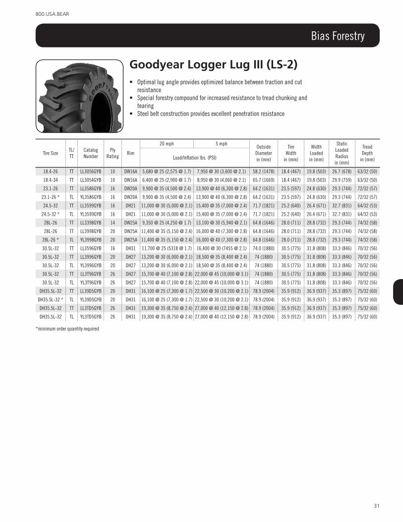
31
800.USA.BEAR
Bias Forestry
Tire SizeTL/TT
CatalogNumber
PlyRating
Rim
20 mph 5 mph Outside
Diameterin (mm)
TireWidth
in (mm)
WidthLoadedin (mm)
Static LoadedRadiusin (mm)
Tread Depth
in (mm)Load/Inflation lbs. (PSI)
18.4-26 TT LL3056GYB 10 DW16A 5,680 @ 25 (2,575 @ 1.7) 7,950 @ 30 (3,600 @ 2.1) 58.2 (1478) 18.4 (467) 19.8 (503) 26.7 (678) 63/32 (50)
18.4-34 TT LL3054GYB 10 DW16A 6,400 @ 25 (2,900 @ 1.7) 8,950 @ 30 (4,060 @ 2.1) 65.7 (1669) 18.4 (467) 19.8 (503) 29.9 (759) 63/32 (50)
23.1-26 TT LL3586GYB 16 DW20A 9,900 @ 35 (4,500 @ 2.4) 13,900 @ 40 (6,300 @ 2.8) 64.2 (1631) 23.5 (597) 24.8 (630) 29.3 (744) 72/32 (57)
23.1-26 * TL YL3586GYB 16 DW20A 9,900 @ 35 (4,500 @ 2.4) 13,900 @ 40 (6,300 @ 2.8) 64.2 (1631) 23.5 (597) 24.8 (630) 29.3 (744) 72/32 (57)
24.5-32 TT LL3599GYB 16 DH21 11,000 @ 30 (5,000 @ 2.1) 15,400 @ 35 (7,000 @ 2.4) 71.7 (1821) 25.2 (640) 26.4 (671) 32.7 (831) 64/32 (53)
24.5-32 * TL YL3599GYB 16 DH21 11,000 @ 30 (5,000 @ 2.1) 15,400 @ 35 (7,000 @ 2.4) 71.7 (1821) 25.2 (640) 26.4 (671) 32.7 (831) 64/32 (53)
28L-26 TT LL3398GYB 14 DW25A 9,350 @ 25 (4,250 @ 1.7) 13,100 @ 30 (5,940 @ 2.1) 64.8 (1646) 28.0 (711) 28.8 (732) 29.3 (744) 74/32 (58)
28L-26 TT LL3998GYB 20 DW25A 11,400 @ 35 (5,150 @ 2.4) 16,000 @ 40 (7,300 @ 2.8) 64.8 (1646) 28.0 (711) 28.8 (732) 29.3 (744) 74/32 (58)
28L-26 * TL YL3998GYB 20 DW25A 11,400 @ 35 (5,150 @ 2.4) 16,000 @ 40 (7,300 @ 2.8) 64.8 (1646) 28.0 (711) 28.8 (732) 29.3 (744) 74/32 (58)
30.5L-32 TT LL3596GYB 16 DH31 11,700 @ 25 (5318 @ 1.7) 16,400 @ 30 (7455 @ 2.1) 74.0 (1880) 30.5 (775) 31.8 (808) 33.3 (846) 70/32 (56)
30.5L-32 TT LL3996GYB 20 DH27 13,200 @ 30 (6,000 @ 2.1) 18,500 @ 35 (8,400 @ 2.4) 74 (1880) 30.5 (775) 31.8 (808) 33.3 (846) 70/32 (56)
30.5L-32 TL YL3996GYB 20 DH27 13,200 @ 30 (6,000 @ 2.1) 18,500 @ 35 (8,400 @ 2.4) 74 (1880) 30.5 (775) 31.8 (808) 33.3 (846) 70/32 (56)
30.5L-32 TT LL3T96GYB 26 DH27 15,700 @ 40 (7,100 @ 2.8) 22,000 @ 45 (10,000 @ 3.1) 74 (1880) 30.5 (775) 31.8 (808) 33.3 (846) 70/32 (56)
30.5L-32 TL YL3T96GYB 26 DH27 15,700 @ 40 (7,100 @ 2.8) 22,000 @ 45 (10,000 @ 3.1) 74 (1880) 30.5 (775) 31.8 (808) 33.3 (846) 70/32 (56)
DH35.5L-32 TT LL39D5GYB 20 DH31 16,100 @ 25 (7,300 @ 1.7) 22,500 @ 30 (10,200 @ 2.1) 78.9 (2004) 35.9 (912) 36.9 (937) 35.3 (897) 75/32 (60)
DH35.5L-32 * TL YL39D5GYB 20 DH31 16,100 @ 25 (7,300 @ 1.7) 22,500 @ 30 (10,200 @ 2.1) 78.9 (2004) 35.9 (912) 36.9 (937) 35.3 (897) 75/32 (60)
DH35.5L-32 TT LL3TD5GYB 26 DH31 19,300 @ 35 (8,750 @ 2.4) 27,000 @ 40 (12,150 @ 2.8) 78.9 (2004) 35.9 (912) 36.9 (937) 35.3 (897) 75/32 (60)
DH35.5L-32 TL YL3TD5GYB 26 DH31 19,300 @ 35 (8,750 @ 2.4) 27,000 @ 40 (12,150 @ 2.8) 78.9 (2004) 35.9 (912) 36.9 (937) 35.3 (897) 75/32 (60)
*minimum order quantity required
Goodyear logger lug iii (ls-2)• Optimal lug angle provides optimized balance between traction and cut
resistance• Special forestry compound for increased resistance to tread chunking and
tearing• Steel belt construction provides excellent penetration resistance

32
www.titan-intl.com
Bias Forestry
Goodyear logger lug iii Hd (ls-2)• Four steel belted construction provides maximum impact and penetration resistance in heavy-duty
service• Optimal lug angle provides optimized balance between traction and cut resistance• Special forestry compound for increased resistance to tread chunking and tearing
Tire SizeTL/TT
CatalogNumber
PlyRating
Rim
20 mph 5 mph Outside
Diameterin (mm)
TireWidth
in (mm)
WidthLoadedin (mm)
Static LoadedRadiusin (mm)
Depthin (32s)
Load/Inflation lbs. (PSI)
23.1-22 TT LL7586GYB 16 DW20A 9,900 @ 35 (4,500 @ 2.4) 13,900 @ 40 (6,300 @ 2.8) 64.2 (1631) 23.5 (597) 24.8 (630) 29.3 (744) 72/32 (57)
24.5-32 TT LL7799GYB 18 DH21 12,000 @ 35 (5,450 @ 2.4) 16,800 @ 40 (7,600 @ 2.8) 71.7 (1821) 25.2 (640) 26.4 (671) 32.7 (831) 64/32 (53)
28L-26 TT LL7598GYB 16 DW25A 10,500 @ 30 (4,750 @ 2.1) 14,700 @ 35 (6,650 @ 2.4) 64.8 (1646) 28.0 (711) 28.8 (732) 29.3 (744) 74/32 (58)
28L-26 TT LL7998GYB 20 DW25A 11,400 @ 35 (5,150 @ 2.4) 16,000 @ 40 (7,300 @ 2.8) 64.8 (1646) 28.0 (711) 28.8 (732) 29.3 (744) 74/32 (58)
28L-26 * TL YL7998GYB 20 DW25A 11,400 @ 35 (5,150 @ 2.4) 16,000 @ 40 (7,300 @ 2.8) 64.8 (1646) 28.0 (711) 28.8 (732) 29.3 (744) 74/32 (58)
30.5L-32 TT LL7996GYB 20 DH27 13,200 @ 30 (6,000 @ 2.1) 18,500 @ 40 (8,400 @2.4) 74.0 (1880) 30.5 (775) 31.8 (808) 33.3 (846) 70/32 (56)
30.5L-32 TT LL7T96GYB 26 DH27 15,700 @ 40 (7,100 @ 2.8) 22,000 @ 45 (10,000 @ 3.1) 74.0 (1880) 30.5 (775) 31.8 (808) 33.3 (846) 70/32 (56)
30.5L-32 * TL YL7T96GYB 26 DH27 15,700 @ 40 (7,100 @ 2.8) 22,000 @ 45 (10,000 @ 3.1) 74.0 (1880) 30.5 (775) 31.8 (808) 33.3 (846) 70/32 (56)
DH35.5L-32 TT LL79D5GYB 20 DH31 16,100 @ 25 (7,300 @ 1.7) 22,500 @ 30 (10,200 @ 2.1) 78.9 (2004) 35.9 (912) 36.9 (937) 35.3 (897) 75/32 (60)
DH35.5L-32 * TL YL79D5GYB 20 DH31 16,100 @ 25 (7,300 @ 1.7) 22,500 @ 30 (10,200 @ 2.1) 78.9 (2004) 35.9 (912) 36.9 (937) 35.3 (897) 75/32 (60)
DH35.5L-32 TT LL7TD5GYB 26 DH31 19,300 @ 35 (8,750 @ 2.4) 27,000 @ 40 (12,150 @ 2.8) 78.9 (2004) 35.9 (912) 36.9 (937) 35.3 (897) 75/32 (60)
DH35.5L-32 * TL YL7TD5GYB 26 DH31 19,300 @ 35 (8,750 @ 2.4) 27,000 @ 40 (12,150 @ 2.8) 78.9 (2004) 35.9 (912) 36.9 (937) 35.3 (897) 75/32 (60)
*minimum order quantity required
Tire SizeCatalogNumber
PlyRating
Rim
30 mph 5 mph Outside
Diameterin (mm)
TireWidth
in (mm)
WidthLoadedin (mm)
Static LoadedRadiusin (mm)
Depthin (32s)
Load/Inflation lbs. (PSI)
66x43.00-25NHS YL33F3GYB 14 36.00TH 12,300 @ 35 (5,600 @ 2.4) 19,400 @ 35 (8,800 @ 2.4) 69.4 (1763) 41.2 (1046) 41.5 (1054) 32.9 (836) 112/32 (89)
66x43.00-25NHS YL33F6GYB 14 DW36A 12,000 @ 35 (5,450 @ 2.4) 19,400 @ 35 (8,800 @ 2.4) 69.4 (1763) 41.2 (1046) 41.5 (1054) 32.9 (836) 112/32 (89)
67x34.00-25NHS YL33R3GYB 14 30.0TH 13,200 @ 40 (6,000 @ 2.8) 20,900 @ 40 (9,500 @ 2.8) 69.4 (1763) 34.1 (866) 34.4 (874) 32.2 (818) 118/32 (94)
67x34.00-25NHS YL3R65GYB 14 DW30A 13,200 @ 40 (6,000 @ 2.8) 20,900 @ 40 (9,500 @ 2.8) 69.4 (1763) 34.1 (866) 34.4 (874) 32.2 (818) 118/32 (94)
DH73x44.00-32* YL35R6GYB 16 DH36 15,200 @ 40 (6,900 @ 2.8) 24,000 @ 40 (10,900 @ 2.8) 74.9 (1902) 41.3 (1049) 41.4 (1052) 35.5 (902) 104/32 (83)
DH73x50.00-32* YL35V6GYB 16 DH44 14,800 @ 35 (6,700 @ 2.4) 23,400 @ 35 (10,600 @ 2.4) 75.3 (1913) 50.1 (1273) -- -- 104/32 (83)
*HF-3+ Tread depth is greater than HF-3 but less than HF-4
Goodyear logger lug iii Flotation (HF-4)• Extra wide tread for high flotation in wet terrain while providing low ground penetration to minimize
environmental impact• Special forestry compound for increased resistance to tread chunking and tearing• Steel belt construction provides excellent penetration resistance
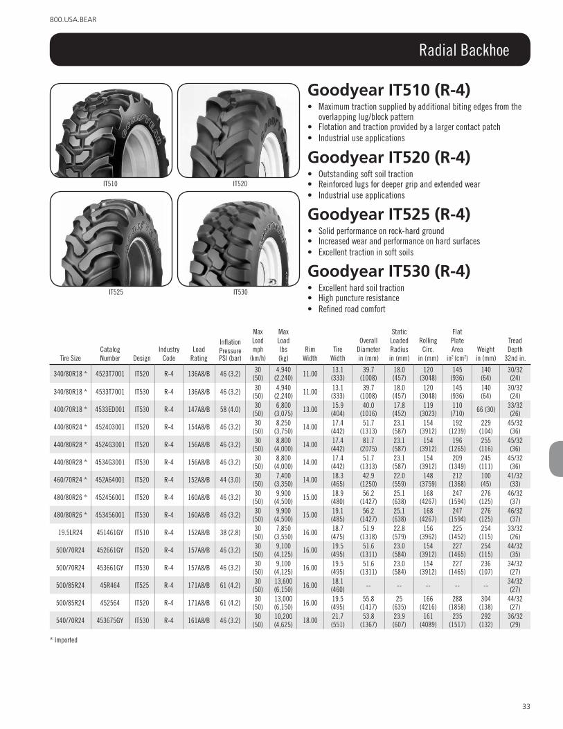
33
800.USA.BEAR
Radial Backhoe
Goodyear iT510 (r-4)• Maximum traction supplied by additional biting edges from the
overlapping lug/block pattern• Flotation and traction provided by a larger contact patch• Industrial use applications
Goodyear iT520 (r-4)• Outstanding soft soil traction• Reinforced lugs for deeper grip and extended wear• Industrial use applications
Goodyear iT530 (r-4)• Excellent hard soil traction• High puncture resistance• Refined road comfort
IT520
IT530
IT510
Goodyear iT525 (r-4)• Solid performance on rock-hard ground• Increased wear and performance on hard surfaces• Excellent traction in soft soils
IT525
Tire SizeCatalog Number Design
Industry Code
Load Rating
Inflation PressurePSI (bar)
Max Load mph
(km/h)
Max Load lbs(kg)
Rim Width
Tire Width
Overall Diameterin (mm)
Static Loaded Radiusin (mm)
Rolling Circ.
in (mm)
Flat Plate Area
in2 (cm2)Weightin (mm)
Tread Depth
32nd in.
340/80R18 * 4523T7001 IT520 R-4 136A8/B 46 (3.2) 30 (50)
4,940 (2,240) 11.00 13.1
(333)39.7
(1008)18.0 (457)
120 (3048)
145 (936)
140 (64)
30/32 (24)
340/80R18 * 4533T7001 IT530 R-4 136A8/B 46 (3.2) 30 (50)
4,940 (2,240) 11.00 13.1
(333)39.7
(1008)18.0 (457)
120 (3048)
145 (936)
140 (64)
30/32 (24)
400/70R18 * 4533ED001 IT530 R-4 147A8/B 58 (4.0) 30 (50)
6,800 (3,075) 13.00 15.9
(404)40.0
(1016)17.8 (452)
119 (3023)
110 (710) 66 (30) 33/32
(26)
440/80R24 * 452403001 IT520 R-4 154A8/B 46 (3.2) 30 (50)
8,250 (3,750) 14.00 17.4
(442)51.7
(1313)23.1 (587)
154 (3912)
192 (1239)
229 (104)
45/32 (36)
440/80R28 * 4524G3001 IT520 R-4 156A8/B 46 (3.2) 30 (50)
8,800 (4,000) 14.00 17.4
(442)81.7
(2075)23.1 (587)
154 (3912)
196 (1265)
255 (116)
45/32 (36)
440/80R28 * 4534G3001 IT530 R-4 156A8/B 46 (3.2) 30 (50)
8,800 (4,000) 14.00 17.4
(442)51.7
(1313)23.1 (587)
154 (3912)
209 (1349)
245 (111)
45/32 (36)
460/70R24 * 452A64001 IT520 R-4 152A8/B 44 (3.0) 30 (50)
7,400 (3,350) 14.00 18.3
(465)42.9
(1250)22.0 (559)
148 (3759)
212 (1368)
100 (45)
41/32 (33)
480/80R26 * 452456001 IT520 R-4 160A8/B 46 (3.2) 30 (50)
9,900 (4,500) 15.00 18.9
(480)56.2
(1427)25.1 (638)
168 (4267)
247 (1594)
276 (125)
46/32 (37)
480/80R26 * 453456001 IT530 R-4 160A8/B 46 (3.2) 30 (50)
9,900 (4,500) 15.00 19.1
(485)56.2
(1427)25.1 (638)
168 (4267)
247 (1594)
276 (125)
46/32 (37)
19.5LR24 451461GY IT510 R-4 152A8/B 38 (2.8) 30 (50)
7,850 (3,550) 16.00 18.7
(475)51.9
(1318)22.8 (579)
156 (3962)
225 (1452)
254 (115)
33/32 (26)
500/70R24 452661GY IT520 R-4 157A8/B 46 (3.2) 30 (50)
9,100 (4,125) 16.00 19.5
(495)51.6
(1311)23.0 (584)
154 (3912)
227 (1465)
254 (115)
44/32 (35)
500/70R24 453661GY IT530 R-4 157A8/B 46 (3.2) 30 (50)
9,100 (4,125) 16.00 19.5
(495)51.6
(1311)23.0 (584)
154 (3912)
227 (1465)
236 (107)
34/32 (27)
500/85R24 45R464 IT525 R-4 171A8/B 61 (4.2) 30 (50)
13,600 (6,150) 16.00 18.1
(460) -- -- -- -- -- 34/32 (27)
500/85R24 452564 IT520 R-4 171A8/B 61 (4.2) 30 (50)
13,000 (6,150) 16.00 19.5
(495)55.8
(1417)25
(635)166
(4216)288
(1858)304
(138)44/32 (27)
540/70R24 453675GY IT530 R-4 161A8/B 46 (3.2) 30 (50)
10,200 (4,625) 18.00 21.7
(551)53.8
(1367)23.9 (607)
161 (4089)
235 (1517)
292 (132)
36/32 (29)
* Imported

34
www.titan-intl.com
Bias Backhoe
Goodyear iT515 Hs (r-4)• Designed for backhoe/loader operations on hard surface• More lugs for improved puncture resistance• Better durability provided by the natural shaped carcass
Goodyear iT525 (r-4)• Solid performance on rock-hard ground• Increased wear and performance on hard surfaces
IT515 IT525
Tire SizeCatalog Number Design
Industry Code
PlyRating
Inflation PressurePSI (bar)
Max Load mph
(km/h)
Max Load lbs(kg)
Rim Width
Tire Width
Overall Diameterin (mm)
Static Loaded Radiusin (mm)
Rolling Circ.
in (mm)
Flat Plate Area
in2 (cm2)Weight
(kg)
Tread Depth 32nd
in.
14.9-24 45T834 IT525 R-4 8 30 (2.1) 25 (40) 5,080 (2,300) 13.00 15.0
(381)48.9
(1242)22.4 (569)
145 (3683)
140 (904)
138 (63)
32/32 (25)
14.9-24 45T134 IT525 R-4 12 42 (2.9) 25 (40) 6,400 (2,900) 13.00 15.0
(381)48.9
(1242)22.4 (569)
145 (3683)
140 (904)
137 (62)
32/32 (25)
16.9-24 45T845 IT525 R-4 8 28 (1.9) 25 (40) 5,840 (2,650) 15.00 16.9
(429) 51 (1295) 23.0 (584)
151 (3835)
194 (1252)
147 (67)
33/32 (26)
16.9-24 45T045 IT525 R-4 10 32 (2.2) 25 (40) 6,400 (2,900) 15.00 16.9
(429) 51 (1295) 23.0 (584)
151 (3835)
194 (1252)
159 (72)
33/32 (26)
16.9-24 45T145 IT525 R-4 12 38 (2.6) 25 (40) 7,150 (3,250) 15.00 16.9
(429) 51 (1295) 23.0 (584)
151 (3835)
194 (1252)
165 (75)
33/32 (26)
16.9-24 45T848 IT525 R-4 8 28 (1.9) 25 (40) 6,150 (2,800) 15.00 16.9
(429)55.5
(1410)25.1 (638)
165 (4191)
223 (1439)
173 (78)
33/32 (26)
16.9-24 45T048 IT525 R-4 10 32 (2.2) 25 (40) 6,800 (3,075) 15.00 16.9
(429)55.5
(1410)25.1 (638)
165 (4191)
223 (1439)
187 (85)
33/32 (26)
16.9-24 45T148 IT525 R-4 12 38 (2.6) 25 (40) 7,600 (3,450) 15.00 16.9
(429)55.5
(1410)25.1 (638)
165 (4191)
223 (1439)
188 (85)
33/32 (26)
17.5L-24 45T803 IT525 R-4 8 26 (1.8) 25 (40) 5,360 (2,430) 15.00 17.4
(442)48.6
(1234)21.9 (556)
144 (3658)
192 (1239)
143 (65)
32/32 (25)
17.5L-24 45T003 IT525 R-4 10 32 (2.2) 25 (40) 6,150 (2,800) 15.00 17.4
(442)48.6
(1234)21.9 (556)
144 (3658)
192 (1239)
184 (83)
32/32 (25)
18.4-24 45T164 IT525 R-4 12 36 (2.5) 25 (40) 8,250 (3,750) 16.00 18.4
(467)54.1
(1374)24.2 (615)
160 (4064)
246 (1588)
189 (86)
34/32 (27)
19.5L-24 45T061 IT525 R-4 10 28 (1.9) 25 (40) 6,600 (3,000) 16.00 19.0
(483)52.0
(1321)23.7 (602)
154 (3912)
206 (1329)
208 (94)
34/32 (27)
19.5L-24 45T161 IT525 R-4 12 34 (2.3) 25 (40) 7,600 (3,400) 16.00 19.0
(483)52.0
(1321)23.7 (602)
154 (3912)
206 (1329)
209 (95)
34/32 (27)
19.5L-24 4H5161 IT515 HS R-4 12 34 (2.3) 25 (40) 7,600 (3,400) 16.00 20.2
(513)52.5
(1334)23.7 (602)
156 (3962)
208 (1342)
216 (98)
34/32 (27)
19.5L-24 45T361 IT525 R-4 14 38 (2.6) 25 (40) 8,250 (3,750) 16.00 19.0
(483)52.0
(1321)23.7 (602)
154 (3912)
238 (1536)
219 (99)
34/32 (27)
21L-24 45T075 IT525 R-4 10 26 (1.8) 25 (40) 7,400 (3,450) 18.00 20.8
(528)54.2
(1377)24.3 (617)
160 (4064)
238 (1536)
249 (113)
34/32 (27)
21L-24 45T175 IT525 R-4 12 32 (2.2) 25 (40) 8,550 (3,875) 18.00 20.8
(528)54.2
(1377)24.3 (617)
160 (4064)
238 (1536)
241 (109)
34/32 (27)
21L-24 45T575 IT525 R-4 16 40 (2.8) 25 (40) 9,900 (4,500) 18.00 20.8
(528)54.2
(1377)24.3 (617)
160 (4064)
238 (1536)
259 (117)
34/32 (27)
21L-28 45T376 IT525 R-4 14 36 (2.5) 25 (40) 9,900 (4,500) 18.00 21.0
(533)58.2
(1478)26.4 (671)
172 (4369)
260 (1678)
269 (122)
34/32 (27)
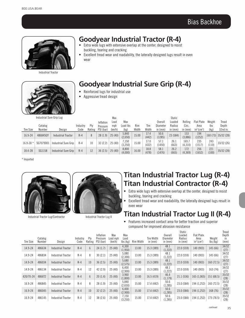
35
800.USA.BEAR
Bias Backhoe
Goodyear industrial sure Grip (r-4)• Reinforced lugs for industrial use• Aggressive tread design
Goodyear industrial Tractor (r-4)• Extra wide lugs with extensive overlap at the center, designed to resist
buckling, tearing and cracking• Excellent tread wear and roadability, the laterally designed lugs result in even
wear
Industrial Tractor
Tire SizeCatalog Number Design
Industry Code
PlyRating
Inflation PressurePSI (bar)
Max Load mph
(km/h)
Max Load lbs
(kg)Rim
WidthTire
Width
Overall Diameterin (mm)
Static Loaded Radiusin (mm)
Rolling Circ.
in (mm)
Flat Plate Area
in2 (cm2)
Weightlbs(kg)
Tread Depth
32nd in.
16.9-24 486845GY Industrial Tractor R-4 8 28 (1.9) 25 (40) 5,840 (2,650) 15.00 17.4
(442)50.6
(1285) 23 (584) 153 (3,886)
194 (1252) 160 (73) 35/32 (28)
16.9-30 * SG7079001 Industrial Sure Grip R-4 10 32 (2.2) 25 (40) 7,150 (3,250) 15.00 17.0
(432)57.1
(1450)26.1 (663)
169.7 (4,310)
235 (1517)
243 (110) 33/32 (26)
18.4-28 SG1158 Industrial Sure Grip R-4 12 36 (2.5) 25 (40) 8,800 (4,000) 16.00 18.8
(478)58.1
(1476)26.2 (665)
172 (4,369)
256 (1652)
221 (100) 35/32 (28)
* Imported
Titan industrial Tractor lug (r-4) Titan industrial contractor (r-4)• Extra wide lugs with extensive overlap at the center, designed to resist
buckling, tearing and cracking• Excellent tread wear and roadability, the laterally designed lugs result in
even wear
Titan industrial Tractor lug ii (r-4)• Features increased contact area for better traction and superior
compound for improved abrasion resistance
Industrial Tractor Lug/Contractor Industrial Tractor Lug II
continued
Tire SizeCatalog Number Design
Industry Code
Ply Rating
Inflation Pressure PSI (bar)
Max Load mph
(km/h)
Max Load
lbs (kg) Rim WidthTire Widthin (mm)
Overall Diameter in (mm)
Static Loaded Radius in (mm)
Flat Plate Area
in2 (cm2)Weight lbs (kg)
Tread Depth
in (mm)
14.9-24 486634 Industrial Tractor R-4 6 24 (1.7) 25 (40) 4,300 (1,950) 13.00 15.3 (389) 48.1
(1,222) 22.0 (559) 140 (903) 145 (66) 34/32 (27)
14.9-24 486834 Industrial Tractor R-4 8 30 (2.1) 25 (40) 5,080 (2,300) 13.00 15.3 (389) 48.1
(1,222) 22.0 (559) 140 (903) 145 (66) 34/32 (27)
14.9-24 486034 Industrial Tractor R-4 10 36 (2.5) 25 (40) 5,680 (2,575) 13.00 15.3 (389) 48.1
(1,222) 22.0 (559) 140 (903) 160 (72.5) 34/32 (27)
14.9-24 486134 Industrial Tractor R-4 12 42 (2.9) 25 (40) 6,400 (2,900) 13.00 15.3 (389) 48.1
(1,222) 22.0 (559) 140 (903) 163 (74) 34/32 (27)
420/70-24 4866T2 Industrial Tractor R-4 6 20 (1.4) 25 (40) 3,960 (1,800) 13.00 16.5 (419) 46.4
(1,179) 21.1 (536) 165 (1,065) 151 (68.5) 35/32 (28)
16.9-24 486845 Industrial Tractor R-4 8 28 (1.9) 25 (40) 5,840 (2,650) 15.00 17.4 (442) 50.6
(1,285) 23.0 (584) 194 (1,252) 160 (72.5) 35/32 (28)
16.9-24 486045 Industrial Tractor R-4 10 32 (2.2) 25 (40) 6,400 (2,900) 15.00 17.4 (442) 50.6
(1,285) 23.0 (584) 194 (1,252) 168 (76) 35/32 (28)
16.9-24 486145 Industrial Tractor R-4 12 38 (2.6) 25 (40) 7,150 (3,250) 15.00 17.4 (442) 50.6
(1,285) 23.0 (584) 194 (1,252) 173 (78.5) 35/32 (28)
Industrial Sure Grip Lug

36
www.titan-intl.com
Bias Backhoe
Titan Grizz lsWG9F (r-4)• This LSW low profile tire is designed to reduce bounce and road lope as well
as better sway-action recovery, while using 25-30% less urethane than a standard tire
Tire SizeCatalog Number Design
Industry Code
Ply Rating
Inflation Pressure PSI (bar)
Max Load mph
(km/h)
Max Load
lbs (kg) Rim WidthTire Widthin (mm)
Overall Diameter in (mm)
Static Loaded Radius in (mm)
Flat Plate Area
in2 (cm2)Weight lbs (kg)
Tread Depth
in (mm)
16.9-24 486345 Industrial Tractor R-4 14 44 (3.0) 25 (40) 7,850 (3,550) 15.00 17.4 (442) 50.6
(1,285) 23.0 (584) 194 (1,252) 174 (79) 35/32 (28)
16.9-28 486848 Industrial Tractor R-4 8 28 (1.9) 25 (40) 6,150 (2,800) 15.00 17.4 (442) 54.6
(1,387) 25.0 (635) 223 (1,439) 178 (80.5) 34/32 (27)
16.9-28 486048 Industrial Tractor R-4 10 32 (2.2) 25 (40) 6,800 (3,075) 15.00 17.4 (442) 54.6
(1,387) 25.0 (635) 223 (1,439) 193 (87.5) 34/32 (27)
16.9-28 486148 Industrial Tractor R-4 12 38 (2.6) 25 (40) 7,600 (3,450) 15.00 17.4 (442) 54.6
(1,387) 25.0 (635) 223 (1,439) 198 (90) 34/32 (27)
17.5L-24 4D6603 Industrial Contractor R-4 6 20 (1.4) 25 (40) 4,400 (2,000) 15.00 17.1 (434) 48.8
(1,240) 22.3 (566) 192 (1,239) 143 (65) 32/32 (25)
17.5L-24 486603 Industrial Tractor R-4 6 20 (1.4) 25 (40) 4,400 (2,000) 15.00 17.1 (434) 48.8
(1,240) 22.3 (566) 192 (1,239) 144 (65.5) 32/32 (25)
17.5L-24 486803 Industrial Tractor R-4 8 26 (1.8) 25 (40) 5,360 (2,430) 15.00 17.1 (434) 48.8
(1,240) 22.3 (566) 192 (1,239) 143 (65) 32/32 (25)
17.5L-24 4D6003 Industrial Contractor R-4 10 32 (2.2) 25 (40) 6,150 (2,800) 15.00 17.1 (434) 48.8
(1,240) 22.3 (566) 192 (1,239) 157 (71) 32/32 (25)
17.5L-24 486003 Industrial Tractor R-4 10 32 (2.2) 25 (40) 6,150 (2,800) 15.00 17.1 (434) 48.8
(1,240) 22.3 (566) 192 (1,239) 157 (71) 32/32 (25)
17.5L-24 4D6103 Industrial Contractor R-4 12 36 (2.5) 25 (40) 6,600 (3,000) 15.00 17.1 (434) 48.8
(1,240) 22.3 (566) 192 (1,239) 164 (74.5) 32/32 (25)
17.5L-24 486103 Industrial Tractor R-4 12 36 (2.5) 25 (40) 6,600 (3,000) 15.00 17.1 (434) 48.8
(1,240) 22.3 (566) 192 (1,239) 164 (74.5) 32/32 (25)
18.4-24 486864 Industrial Tractor R-4 8 24 (1.7) 25 (40) 6,400 (2,900) 16.00 18.8 (478) 53.8
(1,367) 24.4 (620) 246 (1,587) 210 (95.5) 35/32 (28)
18.4-24 486164 Industrial Tractor R-4 12 36 (2.5) 25 (40) 8,250 (3,750) 16.00 18.8 (478) 53.8
(1,367) 24.4 (620) 246 (1,587) 232 (105) 35/32 (28)
18.4-26 486056 Industrial Tractor R-4 10 30 (2.1) 25 (40) 7,600 (3,450) 16.00 18.8 (478) 55.8
(1,417) 25.1 (638) 252 (1,626) 235 (106.5) 35/32 (28)
18.4-26 486156 Industrial Tractor R-4 12 36 (2.5) 25 (40) 8,800 (4,000) 16.00 18.8 (478) 55.8
(1,417) 25.1 (638) 252 (1,626) 235 (106.5) 35/32 (28)
18.4-28 486058 Industrial Tractor R-4 10 30 (2.1) 25 (40) 7,850 (3,550) 16.00 18.8 (478) 57.8
(1,468) 26.4 (671) 256 (1,652) 220 (100) 35/32 (28)
19.5L-24 486861 Industrial Tractor R-4 8 24 (1.7) 25 (40) 6,000 (2,750) 17.00 19.1 (485) 51.8
(1,316) 23.5 (597) 206 (1,329) 195 (88.5) 34/32 (27)
19.5L-24 486061 Industrial Tractor R-4 10 28 (1.9) 25 (40) 6,600 (3,000) 17.00 19.1 (485) 51.8
(1,316) 23.5 (597) 206 (1,329) 207 (94) 34/32 (27)
19.5L-24 486161 Industrial Tractor R-4 12 34 (2.3) 25 (40) 7,600 (3,450) 17.00 19.1 (485) 51.8
(1,316) 23.5 (597) 206 (1,329) 213 (96.5) 34/32 (27)
19.5L-24 49F161 Industrial Tractor II R-4 12 34 (2.3) 25 (40) 7,600 (3,450) 17.00 19.0 (483) 51.6
(1,311) 24.0 (610) 206 (1,329) 213 (96.5) 34/32 (27)
19.5L-24 49F561 Industrial Tractor II R-4 16 44 (3.0) 25 (40) 9,100 (4,125) 17.00 19.0 (483) 51.6
(1,311) 24.0 (610) 206 (1,329) 215 (97.5) 34/32 (27)
21L-24 486075 Industrial Tractor R-4 10 26 (1.8) 25 (40) 7,400 (3,350) 18.00 21.0 (533) 54.3
(1,379) 24.6 (625) 238 (1,535) 250 (113.5) 35/32 (28)
21L-24 486175 Industrial Tractor R-4 12 32 (2.2) 25 (40) 8,550 (3,875) 18.00 21.0 (533) 54.3
(1,379) 24.6 (625) 238 (1,535) 250 (113.5) 35/32 (28)
21L-28 486076 Industrial Tractor R-4 10 22 (1.5) 25 (40) 5,080 (2,300) 18.00 21.0 (533) 58.3
(1,481) 26.6 (676) 260 (1,677) 303 (137.5) 36/32 (29)
21L-28 486176 Industrial Tractor R-4 12 28 (1.9) 25 (40) 5,840 (2,650) 18.00 21.0 (533) 58.3
(1,481) 26.6 (676) 260 (1,677) 309 (140) 36/32 (29)
21L-28 486376 Industrial Tractor R-4 14 36 (2.5) 25 (40) 9,900 (4,500) 18.00 21.0 (533) 58.3
(1,481) 26.6 (676) 260 (1,677) 334 (151.5) 36/32 (29)
Tire SizeCatalog Number
Industry Code
Ply Rating
Inflation Pressure psi (bar)
Max Load mph
(km/h)
Max Load
lbs (kg)Rim
Width inTire Width in (mm)
Overall Diameter in (mm)
Static Loaded
Radius in (mm)
Rolling Circ. in (mm)
Flat Plate Area in2 (cm2)
Weight lbs (kg)
Tread Depth
in (mm)
LSW495-762 G9F161 R-4 12 34 (2.3) 25 (40) 7,600 (3,450) 15.00 19.0 (483) 51.6
(1,311) 24.0 (610) 155 (3,937) -- 225
(102)34/32 (27)
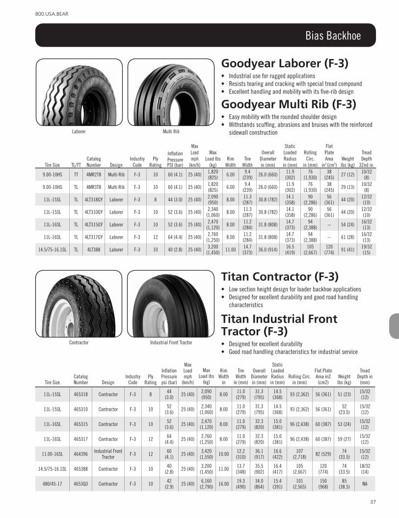
37
800.USA.BEAR
Bias Backhoe
Goodyear laborer (F-3)• Industrial use for rugged applications• Resists tearing and cracking with special tread compound• Excellent handling and mobility with its five-rib design
Goodyear Multi rib (F-3)• Easy mobility with the rounded shoulder design• Withstands scuffing, abrasions and bruises with the reinforced
sidewall construction
Tire Size TL/TTCatalog Number Design
Industry Code
Ply Rating
Inflation PressurePSI (bar)
Max Load mph
(km/h)
Max Load lbs
(kg)Rim
WidthTire
Width
Overall Diameterin (mm)
Static Loaded Radiusin (mm)
Rolling Circ.
in (mm)
Flat Plate Area
in2 (cm2)Weightlbs (kg)
Tread Depth
32nd in.
9.00-10HS TT 4MR2T8 Multi Rib F-3 10 60 (4.1) 25 (40) 1,820 (825) 6.00 9.4
(239) 26.0 (660) 11.9 (302)
76 (1,930)
38 (245) 27 (12) 10/32
(8)
9.00-10HS TL 4MR3T8 Multi Rib F-3 10 60 (4.1) 25 (40) 1,820 (825) 6.00 9.4
(239) 26.0 (660) 11.9 (302)
76 (1,930)
38 (245) 29 (13) 10/32
(8)
11L-15SL TL 4LT318GY Laborer F-3 8 44 (3.0) 25 (40) 2,090 (950) 8.00 11.3
(287) 30.8 (782) 14.1 (358)
90 (2,286)
56 (361) 44 (20) 12/32
(10)
11L-15SL TL 4LT310GY Laborer F-3 10 52 (3.6) 25 (40) 2,340 (1,060) 8.00 11.3
(287) 30.8 (782) 14.1 (358)
90 (2,286)
56 (361) 44 (20) 12/32
(10)
11L-16SL TL 4LT315GY Laborer F-3 10 52 (3.6) 25 (40) 2,470 (1,120) 8.00 11.2
(284) 31.8 (808) 14.7 (373)
94 (2,388) -- 54 (24) 16/32
(13)
11L-16SL TL 4LT317GY Laborer F-3 12 64 (4.4) 25 (40) 2,760 (1,250) 8.00 11.2
(284) 31.8 (808) 14.7 (373)
94 (2,388) -- 61 (28) 16/32
(13)
14.5/75-16.1SL TL 4LT388 Laborer F-3 10 40 (2.8) 25 (40) 3,200 (1,450) 11.00 14.7
(373) 36.0 (914) 16.5 (419)
105 (2,667)
120 (774) 91 (41) 19/32
(15)
Laborer Multi Rib
Titan contractor (F-3)• Low section height design for loader backhoe applications• Designed for excellent durability and good road handling
characteristics
Titan industrial Front Tractor (F-3)• Designed for excellent durability• Good road handling characteristics for industrial service
Contractor Industrial Front Tractor
Tire SizeCatalog Number Design
Industry Code
Ply Rating
Inflation Pressure psi (bar)
Max Load mph
(km/h)
Max Load lbs
(kg)
Rim Width
in
Tire Width
in (mm)
Overall Diameter in (mm)
Static Loaded Radius in (mm)
Rolling Circ. in (mm)
Flat Plate Area in2 (cm2)
Weight lbs (kg)
Tread Depth in
(mm)
11L-15SL 465318 Contractor F-3 8 44 (3.0) 25 (40) 2,090
(950) 8.00 11.0 (279)
31.3 (795)
14.5 (368) 93 (2,362) 56 (361) 51 (23) 15/32
(12)
11L-15SL 465310 Contractor F-3 10 52 (3.6) 25 (40) 2,340
(1,060) 8.00 11.0 (279)
31.3 (795)
14.5 (368) 93 (2,362) 56 (361) 52
(23.5)15/32 (12)
11L-16SL 465315 Contractor F-3 10 52 (3.6) 25 (40) 2,470
(1,120) 8.00 11.0 (279)
32.3 (820)
15.0 (381) 96 (2,438) 60 (387) 53 (24) 15/32
(12)
11L-16SL 465317 Contractor F-3 12 64 (4.4) 25 (40) 2,760
(1,250) 8.00 11.0 (279)
32.3 (820)
15.0 (381) 96 (2,438) 60 (387) 59 (27) 15/32
(12)
11.00-16SL 464396 Industrial Front Tractor F-3 12 60
(4.1) 25 (40) 3,420 (1,550) 10.00 12.2
(310)36.1 (917)
16.6 (422)
107 (2,718) 82 (529) 74
(33.5)15/32 (12)
14.5/75-16.1SL 465388 Contractor F-3 10 40 (2.8) 25 (40) 3,200
(1,450) 11.00 13.7 (348)
35.5 (902)
16.4 (417)
105 (2,667)
120 (774)
74 (33.5)
18/32 (14)
480/45-17 4653Q3 Contractor F-3 10 42 (2.9) 25 (40) 6,160
(2,790) 16.00 19.3 (490)
34.0 (864)
15.4 (391)
101 (2,565)
150 (968)
85 (38.5) NA

38
www.titan-intl.com
Bias Backhoe
Goodyear sure Grip implement (i-3)• Traction for all types of farm implements• Improved tread wear from the flared lug design at the centerline
Goodyear sure Grip lug (i-3)• Good choice for industrial equipment• Good traction and long wear• Wide, sturdy overlapping lugs
Sure Grip Implement Sure Grip Lug
Tire SizeCatalog Number Design
Industry Code
Ply Rating
Inflation Pressure PSI (bar)
Max Load
lbs (kg)
Max Load
lbs (kg)Rim
Width
Tire Width in
(mm)
Overall Diameter in (mm)
Static Loaded Radius in (mm)
Rolling Circ.
in (mm)
Flat Plate Area
in2 (cm2)Weight lbs (kg)
Tread Depth
32nd in.
10.5/80-18 * 4GL3J8001 Sure Grip Lug I-3 10 54 (3.7) 25 (40) 3,840 (1,740) 9.00 10.7
(272) 35.7 (907) 16.0 (406)
108 (2,743) 11 (71) 65 (29) 29/32
(23)
10.5/80-18 * 4G13J8001 Sure Grip Implement I-3 10 54 (3.7) 25 (40) 3,840 (1,740) 9.00 10.7
(272) 35.7 (907) 16.0 (406)
108 (2,743) 11 (71) 65 (29) 29/32
(23)
12.4-16 46W483GY Sure Grip Lug I-3 4 20 (1.4) 25 (40) 2,070 (940) 11.00 12.8
(325) 36.9 (937) 16.7 (424)
110 (2,794) -- 82 (37) 30/32
(24)
12.5/80-18 4GL5J9 Sure Grip Lug I-3 14 62 (4.3) 25 (40) 6,600 (3,000) 9.00 12.0
(305) 39.0 (991) 17.3 (439)
119 (3,023) 145 (936) 100
(45)31/32 (25)
12.5/80-18 * 4G13J9001 Sure Grip Implement I-3 10 45 (3.1) 25 (40) 4,820 (2,185) 9.00 12.4
(315) 38.7 (983) 17.2 (437)
116 (2,946) 145 (936) 75 (34) 31/32
(25)
* Imported
Titan contractor (i-3)• An implement tire specially designed for high traction
applications• Frequently used on the front of backhoes, this tire is available in
10-ply construction
Titan contractor ii (i-3)• A more robust design for use on the front of large backhoes
Titan Ti422 (i-3)• Designed for low horsepower traction requirements, the Traction
Implement offers good roadability and excellent durability
Contractor Contractor II
TI422
Titan Grizz lsW G2E (i-3)• Designed for the front position of large backhoes• This LSW size can replace the popular 12.5/80-18 front backhoe
tire, yet gives LSW stabilityGrizz LSW G2E
Tire SizeCatalog Number Design
Industry Code
Ply Rating
Inflation Pressure psi (bar)
Max Load mph
(km/h)Max Load lbs (kg)
Rim Width
inTire Width in (mm)
Overall Diameter in (mm)
Static Loaded Radius in (mm)
Rolling Circ. in (mm)
Flat Plate
Area in2 (cm2)
Weight lbs (kg)
Tread Depth in
(mm)
10.5/80-18 46W3X8 Contractor I-3 6 33 (3.3) 25 (40) 2,830 (1,285) 9.00 10.8 (274) 35.7
(907)16.5 (419)
109 (2,769) --- 69 (31.5) 29/32 (23)
10.5/80-18 46W3J8 Contractor I-3 10 54 (3.7) 25 (40) 3,840 (1,740) 9.00 10.8 (274) 35.7
(907)16.5 (419)
109 (2,769) --- 71 (32) 29/32 (23)
12.5/80-18 46W39N Contractor I-3 6 28 (1.9) 25 (40) 3,420 (1,550) 9.00 12.0 (305) 38.8
(986)17.4 (442)
114 (2,896) --- 92 (41.5) 31/32 (25)
12.5/80-18 46W3J9 Contractor I-3 10 46 (3.2) 25 (40) 4,710 (2,140) 9.00 12.0 (305) 38.8
(986)17.4 (442)
114 (2,896) --- 98 (44.5) 31/32 (25)
12.5/80-18 4223J9 TI422 I-3 10 46 (3.2) 25 (40) 4,710 (2,140) 9.00 12.0 (305) 38.8
(986)17.4 (442)
114 (2,896) --- 86 (39) 34/32 (27)
12.5/80-18 42E3J9 Contractor II I-3 10 46 (3.2) 25 (40) 4,710 (2,140) 9.00 12.0 (305) 39.1
(993)18.0 (457)
117 (2,972) --- 88 (40) 32/32 (25)
12.5/80-18 42E3T7 Contractor II I-3 12 56 (3.9) 25 (40) 5,360 (2,430) 9.00 12.0 (305) 39.1
(993)18.0 (457)
117 (2,972) --- 90 (41) 32/32 (25)
LSW320-597 G2E3T7 LSW G2E I-3 12 56 (3.9) 25 (40) 5,360 (2,430) 9.00 12.0 (305) 39.1
(993)18.0 (457)
117 (2,972) --- 114 (51.5) 32/32 (25)

39
800.USA.BEAR
Bias Skid Steer
Tire SizeCatalog Number Design
Ply Rating
Inflation PressurePSI (bar)
Max Load mph
Max Load lbs
(kg)
Rim Width
in
Tire Width
in (mm)
Overall Diameterin (mm)
Static Loaded Radiusin (mm)
Rolling Circ.
in (mm)
Flat Plate Area
in2 (cm2
Weightlbs (kg)
Tread Depth
in (mm)
23x8.50-12NHS 4323C3 IT323 4 35 (2.4) 5 (10) 1,470 (665) 7.00 8.4
(213)22.6 (574)
10.1 (257)
63.0 (1,600) --- 23 (10) 16/32
(13)
27x8.50-15NHS 4GL3J3GY Sure Grip Lug 4 35 (2.4) 5 (10) 1,840 (835) 7.00 8.5
(216)27.2 (691)
12.2 (310)
79.0 (2,007) --- 29 (13) 18/32
(14)
27x8.50-15NHS 4GL339GY Sure Grip Lug 6 45 (3.1) 5 (10) 2,480 (1,125) 7.00 8.5
(216)27.2 (691)
12.2 (310)
79.0 (2,007) --- 30 (14) 18/32
(14)
27x8.50-15NHS 432339 IT323 6 45 (3.1) 5 (10) 2,480 (1,125) 7.00 8.8
(224)27.2 (691)
12.2 (310)
79.0 (2,007) --- 38 (17) 18/32
(14)
27x10.50-15NHS 4233L6 IT323 4 30 (2.1) 5 (10) 2,085 (945) 8.50 10.0
(254)27.2 (691)
12.7 (323)
82.3 (2,090) --- 43 (20) 20/32
(16)
27x10.50-15NHS 4323H7 IT323 6 45 (3.1) 5 (10) 2,610 (1,185) 8.50 10.0
(254)27.2 (691)
12.7 (323)
82.3 (2,090) --- 44 (20) 20/32
(16)
27x10.50-15NHS 4GL3H7 Sure Grip Lug 6 45 (3.1) 5 (10) 2,610 (1,185) 8.50 10.3
(262)27.2 (691)
12.7 (323)
82.0 (2,083) --- 37 (17) 18/32
(14)
10-16.5NHS 4GL3C8 Sure Grip Lug 6 45 (3.1) 5 (10) 3,500 (1,590) 8.25 10.9
(277)30.4 (772)
14.1 (358)
91.0 (2,311) --- 50 (23) 21/32
(17)
10-16.5NHS 4323D1GY IT323 8 60 (4.1) 5 (10) 4,140 (1,880) 8.25 10.8
(274)30.6 (777)
14.2 (361)
92.4 (2,347) --- 61 (28) 25/32
(20)
31x15.50-15NHS 4323L8 IT323 8 35 (2.4) 5 (10) 4,480 (2,030) 12.00 15.7
(399)31.5 (800)
13.9 (353)
90.0 (2,286) --- 80 (36) 25/32
(20)
12-16.5NHS 4GL3E8 Sure Grip Lug 8 50 (3.4) 5 (10) 4,810 (2,180) 9.75 12.6
(320)32.7 (831)
14.8 (376)
98.0 (2,489) --- 69 (31) 23/32
(18)
12-16.5NHS 4GL3J7 Sure Grip Lug 10 65 (4.5) 5 (10) 5,600 (2,540) 9.75 12.6
(320)32.7 (831)
14.8 (376)
98.0 (2,489) --- 71 (32) 23/32
(18)
12-16.5NHS 4323E8GY IT323 8 50 (3.4) 5 (10) 4,810 (2,180) 9.75 12.7
(323)32.9 (836)
14.9 (378)
99.0 (2,515) --- 73 (33) 26/32
(21)
12-16.5NHS 4323J7GY IT323 10 65 (4.5) 5 (10) 5,600 (2,540) 9.75 12.7
(323)32.9 (836)
14.9 (378)
99.0 (2,515) --- 76 (34) 26/32
(21)
15-19.5NHS 432336 IT323 12 60 (4.1) 5 (10) 9,190 (4,170) 11.75 15.3
(389)40.1
(1,019)18
(457)117.0
(2,972) --- 137 (62)
30/32 (24)
15-19.5NHS 4GL336 Sure Grip Lug 12 60 (4.1) 5 (10) 9,190 (4,170) 11.75 15.9
(404)40.1
(1,019)18
(457)117.0
(2,972) --- 132 (60)
26/32 (21)
Goodyear iT323• 115 level non-skid depth• Heavier under tread• Sidewall scuff rib• Wear pad design for better wear
Goodyear sure Grip lug• Directional design for excellent traction• For use in soft soil operations where traction and flotation are
required
Sure Grip LugTI323

40
www.titan-intl.com
Bias Skid Steer
Tire Size Catalog Number DesignPly
Rating
Inflation Pressure PSI (bar)
Max Load mph
(km/h)
Max Load
lbs (kg)Rim
Width
Tire Width in
(mm)
Overall Diameter in (mm)
Static Loaded Radius in (mm)
Rolling Circ.
in (mm)
Flat Plate Area
in2 (cm2)Weight lbs (kg)
Tread Depth
in (mm)
5.70-12NHS 4123C2 Trac Loader Chevron 4 60 (4.1) 5 (10) 1,450 (660) 4.50 5.7
(145) 22.4 (569) 10.3 (262)
67 (1,702) --- 17 (7.5) 18/32
(14)
7.00-15SS 4123C5 Trac Loader Chevron 6 60 (4.1) 5 (10) 3,180 (1,440) 5.50 8.0
(203) 29.9 (759) 13.5 (343)
88 (2,235) --- 38 (17) 18/32
(14)
8.25-15NHS 4127K5 Trac Loader Chevron 6 50 (3.4) 5 (10) 3,860 (1,750) 6.00 9.4
(239) 33.2 (843) 14.9 (378)
98 (2,489) --- 53 (24) 18/32
(14)
10-16.5NHS 4123C8 Trac Loader 6 45 (3.1) 5 (10) 3,500 (1,590) 8.30 10.9
(277) 30.3 (770) 13.5 (343)
90 (2,286) --- 48 (22) 19/32
(15)
10-16.5NHS 4393D1 HD2000 8 60 (4.1) 5 (10) 4,140 (1,880) 8.25 10.3
(262) 30.6 (777) 14.3 (363)
92 (2,337) --- 55 (25) 21/32
(17)
10-16.5NHS 49E3D1 HD2000II 8 60 (4.1) 5 (10) 4,140 (1,880) 8.25 10.5
(267) 30.3 (770) 14.1 (358)
91 (2,311) --- 55 (25) 24/32
(19)
10-16.5NHS 4393D1TYL HD2000* 8 60 (4.1) 5 (10) 4,140 (1,880) 8.25 10.3
(262) 30.6 (777) 14.3 (363)
92 (2,337) --- 74
(33.5)21/32 (17)
10-16.5NHS 49E3D1TYL HD2000II* 8 60 (4.1) 5 (10) 4,140 (1,880) 8.25 10.5
(267) 30.3 (770) 14.1 (358)
91 (2,311) --- 83
(37.5)24/32 (19)
10-16.5NHS 4393R8 HD2000 10 75 (5.0) 5 (10) 4,710 (2,135) 8.25 10.3
(262) 30.6 (777) 14.3 (363)
92 (2,337) --- 55 (25) 21/32
(17)
12-16.5NHS 4393C9 HD2000 6 40 (2.8) 5 (10) 4,220 (1,915) 9.75 12.8
(325) 32.7 (831) 15.3 (389)
99 (2,515) --- 71 (32) 23/32
(18)
12-16.5NHS 4123C9 Trac Loader 6 40 (2.8) 5 (10) 4,220 (1,915) 9.75 12.1
(307) 33.6 (853) 15.1 (384)
101 (2,565) --- 66 (30) 23/32
(18)
Titan contractor FWd• Excellent traction and wear are the benefits of the broad, curved lugs • High strength construction gives it exceptional durability
Titan Hd2000• Engineered with HD sidewalls to protect against abrasions, tears and
punctures• Improved dual tapered step lug wear and extended life
Titan Hd2000 ii• Titan’s premium conventional skid steer tire with deeper tread depth,
premium compound, larger tread lugs, heavier sidewall and larger rim guard
Titan Trac loader• The tire preferred by major manufacturers of uniloaders and skid steer
equipment• Constructed with a superior blend of natural and synthetic rubber• Center lug design adds extra traction
Titan Trac loader chevron• Features a chevron tread pattern with nylon fabric construction• Intended for skid steer use
Contractor FWD
HD2000 HD2000 II
Trac Loader Trac Loader Chevron
*w/Tyrelyner

41
800.USA.BEAR
Bias Skid Steer
Tire Size Catalog Number DesignPly
Rating
Inflation Pressure PSI (bar)
Max Load mph
(km/h)
Max Load
lbs (kg)Rim
Width
Tire Width in
(mm)
Overall Diameter in (mm)
Static Loaded Radius in (mm)
Rolling Circ.
in (mm)
Flat Plate Area
in2 (cm2)Weight lbs (kg)
Tread Depth
in (mm)
12-16.5NHS 46C3E8 Contractor FWD 8 50 (3.4) 5 (10) 4,810 (2,180) 9.75 11.8
(300) 33.1 (841) 14.9 (378)
98 (2,489) --- 68 (31) 23/32
(18)
12-16.5NHS 4123D2 Trac Loader 8 50 (3.4) 5 (10) 4,810 (2,180) 9.75 12.2
(310) 33.6 (853) 15.1 (384)
101 (2,565) --- 68 (31) 23/32
(18)
12-16.5NHS 46C3J7 Contractor FWD 10 65 (4.5) 5 (10) 5,600 (2,540) 9.75 11.8
(300) 33.1 (841) 14.9 (378)
98 (2,489) --- 70 (32) 23/32
(18)
12-16.5NHS 4393J7 HD2000 10 65 (4.5) 5 (10) 5,600 (2,540) 9.75 12.8
(325) 32.7 (831) 15.3 (389)
99 (2,515) --- 74
(33.5)23/32 (18)
12-16.5NHS 4393J7TYL HD2000 * 10 65 (4.5) 5 (10) 5,600 (2,540) 9.75 12.2
(310) 32.7 (831) 15.0 (381)
97 (2,464) --- 99 (45) 26/32
(21)
12-16.5NHS 49E3J7 HD2000II 10 65 (4.5) 5 (10) 5,600 (2,540) 9.75 12.2
(310) 32.7 (831) 15.0 (381)
97 (2,464) --- 74
(33.5)26/32 (21)
12-16.5NHS 49E3J7TYL HD2000II * 10 65 (4.5) 5 (10) 5,600 (2,540) 9.75 12.2
(310) 32.7 (831) 15.0 (381)
97 (2,464) --- 74
(33.5)26/32 (21)
12-16.5NHS 4123J7 Trac Loader 10 65 (4.5) 5 (10) 5,600 (2,540) 9.75 12.2
(310) 33.6 (853) 15.1 (384)
101 (2,565) --- 71 (32) 23/32
(18)
12-16.5NHS 4393J8 HD2000 12 80 (5.5) 5 (10) 6,320 (2,865) 9.75 12.8
(325) 32.7 (831) 15.3 (389)
99 (2,515) --- 70 (32) 23/32
(18)
12-16.5NHS 49E34R HD2000II 14 90 (6.2) 5 (10) 6,780 (3,075) 9.75 12.2
(310) 32.7 (831) 15.0 (381)
97 (2,464) --- 82 (37) 26/32
(21)
14-17.5NHS 412334 Trac Loader 6 30 (2.1) 5 (10) 4,820 (2,185) 10.50 14.0
(356) 36.9 (937) 16.3 (414)
109 (2,769) --- 89
(40.5)24/32 (19)
14-17.5NHS 46C3G9 Contractor FWD 10 55 (3.8) 5 (10) 6,850 (3,105) 10.50 13.8
(351) 36.3 (922) 16.3 (414)
108 (2,743) --- 83
(37.5)24/32 (19)
14-17.5NHS 439396 HD2000 10 55 (3.8) 5 (10) 6,850 (3,105) 10.50 13.8
(351) 37.2 (945) 17.6 (447)
113 (2,870) --- 92
(41.5)24/32 (19)
14-17.5NHS 412396 Trac Loader 10 55 (3.8) 5 (10) 6,850 (3,105) 10.50 14.0
(356) 36.9 (937) 16.3 (414)
109 (2,769) --- 92
(41.5)24/32 (19)
14-17.5NHS 439349 HD2000 12 65 (4.5) 5 (10) 7,550 (3,420) 10.50 13.8
(351) 37.2 (945) 17.6 (447)
113 (2,870) --- 99 (45) 24/32
(19)
14-17.5NHS 439384 HD2000 14 80 (5.5) 5 (10) 8,540 (3,875) 10.50 13.8
(351) 37.2 (945) 17.6 (447)
113 (2,870) --- 101 (46) 24/32
(19)
14-17.5NHS 49E384 HD2000II 14 80 (5.5) 5 (10) 8,540 (3,875) 10.50 15.2
(386) 35.7 (907) 16.4 (417)
107 (2,718) --- 119 (54) 26/32
(21)
14-17.5NHS 412384 Trac Loader 14 80 (5.5) 5 (10) 8,540 (3,875) 10.50 14.3
(363) 36.4 (925) 16.4 (417)
107 (2,718) --- 101 (46) 24/32
(19)
15-19.5NHS 412373 Trac Loader 6 30 (2.1) 5 (10) 6,130 (2,780) 11.75 15.5
(394)40.5
(1,029)17.9 (455)
117 (2,972) --- 112 (51) 25/32
(20)
15-19.5NHS 46C3H9 Contractor FWD 8 40 (2.8) 5 (10) 7,250 (3,290) 11.75 15.3
(389)40.1
(1,019) 18 (457) 119 (3,023) --- 110 (50) 26/32
(21)
15-19.5NHS 439336 HD2000 12 60 (4.1) 5 (10) 9,190 (4,170) 11.75 15.7
(399)40.5
(1,029)19.2 (488)
123 (3,124) --- 134 (61) 26/32
(21)
15-19.5NHS 412336 Trac Loader 12 60 (4.1) 5 (10) 9,190 (4,170) 11.75 15.5
(394)40.5
(1,029)17.9 (455)
117 (2,972) --- 132 (60) 25/32
(20)
15-19.5NHS 439636 HD2000 16 85 (5.9) 5 (10) 11,270 (5,100) 11.75 15.7
(399)40.5
(1,029)19.2 (488)
123 (3,124) --- 148 (67) 26/32
(21)
18x8.50-10 4123U1 Trac Loader 4 22 (1.5) 5 (10) 830 (375) 7.00 7.5
(191) 17.7 (450) 8.1 (206) 53 (1,346)
38 (245) 15 (7) 16/32
(13)
20x8.00-10NHS 49E3W8 HD2000II 4 40 (2.8) 5 (10) 1,210 (550) 6.00 8.2
(208) 19.3 (490) 8.8 (224) 57 (1,448) --- 21 (9.5) 15/32
(12)
23x8.50-12NHS 4123C3 Trac Loader 4 35 (2.4) 5 (10) 1,470 (665) 7.00 8.3
(211) 23.0 (584) 10.2 (259)
68 (1,727) --- 26 (12) 14/32
(11)
23x8.50-12NHS 4393G8 HD2000 6 50 (3.4) 5 (10) 1,810 (820) 7.00 8.7
(221) 23.5 (597) 11.0 (279)
71 (1,803) --- 27 (12) 14/32
(11)
23x8.50-12NHS 4123G8 Trac Loader 6 50 (3.4) 5 (10) 1,810 (820) 7.00 8.3
(211) 23.0 (584) 10.2 (259)
68 (1,727) --- 26 (12) 14/32
(11)
23x8.50-14NHS 412388 Trac Loader 4 35 (2.4) 5 (10) 1,490 (647) 7.00 7.8
(198) 23.8 (605) 10.7 (272)
71 (1,803) --- 24 (11) 14/32
(11)
25x8.50-14NHS 412379 Trac Loader 6 50 (3.4) 5 (10) 2,000 (905) 7.00 8.4
(213) 25.9 (658) 11.8 (300)
79 (2,007) --- 30
(13.5)17/32 (13)
26x12.0-12NHS 412361 Trac Loader 4 20 (1.4) 5 (10) 1,780 (805) 10.50 12.2
(310) 25.5 (648) 11.3 (287)
77 (1,956)
84 (542)
32 (14.5)
16/32 (13)
27x8.50-15NHS 46C3J3 Contractor FWD 4 35 (2.4) 5 (10) 1,840 (835) 7.00 8.1
(206) 27.2 (691) 12.4 (315)
81 (2,057) --- 34
(15.5)19/32 (15)
27x8.50-15NHS 4123C6 Trac Loader 4 30 (2.1) 5 (10) 1,940 (880) 7.00 8.8
(224) 27.0 (686) 12.1 (307)
81 (2,057) --- 36
(16.5)17/32 (13)
27x8.50-15NHS 412339 Trac Loader 6 45 (3.1) 5 (10) 2,480 (1,120) 7.00 8.8
(224) 27.0 (686) 12.1 (307)
81 (2,057) --- 36
(16.5)17/32 (13)
27x8.50-15NHS 439377 HD2000 8 60 (4.1) 5 (10) 2,890 (1,340) 7.00 8.6
(218) 26.8 (681) 12.5 (318)
81 (2,057) --- 38 (17) 15/32
(12)
27x10.50-15NHS 4123H7 Trac Loader 6 45 (3.1) 5 (10) 2,610 (1,180) 8.50 11.0
(279) 27.5 (699) 12.3 (312)
82 (2,083) --- 38 (17) 17/32
(13) *w/Tyrelyner

42
www.titan-intl.com
Bias Skid Steer
Titan Ultimate• Extra long life with up to twice the tread depth of conventional skid steer tires.• Superior damage resistance due to extra heavy sidewall and large rim guard.• Superior traction from high void-to-lug ratio.• Lowest possible cost per hour delivered by specialty compound and industry leading
tread depth.
Titan H/E• The H/E is Titan’s premium deep tread skid steer tire, designed for use
in severe applications such as concrete planing, asphalt recycling, demolition areas, quarries, glass plants and scrap yards
Tire Size Catalog Number DesignPly
Rating
Inflation Pressure PSI (bar)
Max Load mph
(km/h)
Max Load
lbs (kg)Rim
Width
Tire Width in
(mm)
Overall Diameter in (mm)
Static Loaded Radius in (mm)
Rolling Circ.
in (mm)
Flat Plate Area
in2 (cm2)Weight lbs (kg)
Tread Depth
in (mm)
27x10.50-15NHS 439378 HD2000 8 60 (4.1) 5 (10) 3,100 (1,410) 8.50 10.2
(249) 27.1 (688) 12.8 (325)
82 (2,083) --- 46 (21) 15/32
(12)
27x12.5-15NHS 4122N7 Trac Loader 4 25 (1.8) 5 (10) 2,320 (1,050) 10.00 12.5
(318) 27.1 (688) 12.3 (312)
82 (2,083) --- 45
(20.5)17/32 (13)
28x8.50-15NHS 4123R3 Trac Loader 6 45 (3.1) 5 (10) 2,880 (1,310) 7.00 8.4
(213) 28.0 (711) 12.8 (325)
83 (2,108) --- 28
(12.5)17/32 (13)
30.5x12-16.5NHS 439381 HD2000 8 45 (3.1) 5 (10) 3,840 (1,740) 9.75 12.5
(318) 30.8 (782) 14.0 (356)
91 (2,311) --- 74
(33.5)21/32 (17)
31x15.50-16.5NHS 49E3L8 HD2000II 8 35 (2.4) 5 (10) 4,480 (2,030) 12.00 15.5
(394) 31.0 (787) 14.1 (358)
92 (2,337) --- 85
(38.5)24/32 (19)
33x14.5-16.5NHS 4123J9 Trac Loader 8 40 (2.8) 5 (10) 4,690 (2,130) 12.00 14.5
(368) 33.0 (838) 14.9 (378)
98 (2,489) --- 72
(32.5)23/32 (18)
33x15.5-16.5NHS 49E3X3 HD2000II 12 60 (4.1) 5 (10) 6,835 (3,100) 12.00 15.5
(394) 33.0 (838) 15.0 (381)
98 (2,489) --- 103
(46.5)24/32 (19)
33x15.5-16.5NHS 49E3R9 HD2000II 14 70 (4.8) 5 (10) 7,480 (3,390) 12.00 15.5
(394) 33.0 (838) 15.0 (381)
98 (2,489) --- 103
(46.5)24/32 (19)
43x16.00-20NHS 4123A5 Trac Loader 4 20 (1.4) 5 (10) 4,540 (2,060) 14.00 16.0
(406)43.5
(1,105)19.3 (490)
129 (3,277) --- 125
(56.5)26/32 (21)
Tire SizeCatalog Number Design
PlyRating
Inflation Pressure PSI (bar)
Max Load mph
(km/h)
Max Load
lbs (kg)Rim
Width inTire Width in (mm)
Overall Diameter in (mm)
Static Loaded Radius in (mm)
Rolling Circ.
in (mm)
Flat Plate Area
in2 (cm2)Weight lbs (kg)
Tread Depth in (mm)
10-16.5NHS 49U3D1 Ultimate 8 60 (4.1) 5 (10) 4,140 (1,880) 8.25 10.7 (272) 30.1 (765) 25.9 (658) 91 (2,311) --- 70 (32) 42/32 (33)
10-16.5NHS 43H3R8 H/E 10 75 (5.2) 5 (10) 4,710 (2,135) 8.25 10.4 (264) 30.6 (777) 13.7 (348) 89 (2,261) --- 88 (40) 44/32 (35)
12-16.5NHS 49U3J7 Ultimate 10 65 (4.5) 5 (10) 5,600 (2,540) 9.75 12.1 (307) 32.7 (831) 14.9 (378) 98 (2,489) --- 91 (41.5) 44/32 (35)
12-16.5NHS 43H34R H/E 14 90 (6.2) 5 (10) 6,780 (3,075) 9.75 12.0 (305) 32.7 (831) 15.0 (381) 97 (2,464) --- 103
(46.5) 44/32 (35)
14-17.5NHS 43H384 H/E 14 80 (5.5) 5 (10) 8,540 (3,875) 10.50 14.1 (358) 36.6 (930) 17.0 (432) 110 (2,794) --- 139 (63) 47/32 (37)
33x15.5-16.5NHS 43H3X3 H/E 12 60 (4.1) 5 (10) 6,835 (3,100) 12.00 14.5 (368) 33.0 (838) 14.7 (373) 99 (2,515) --- 119 (54) 48/32 (38)

43
800.USA.BEAR
Bias Skid Steer
Titan Grizz lsWG9a• Premium LSW skid steer tire with all the features of the HD2000 II, plus run-
flat capability• LSW assemblies reduce bounce and lope, and improve lateral stability
Tire SizeCatalog Number
Ply Rating
Inflation Pressure PSI (bar)
Max Load mph
(km/h)
Max Load
lbs (kg)Rim
WidthTire Width in (mm)
Overall Diameter in (mm)
Static Loaded Radius in (mm)
Rolling Circ. in (mm)
Flat Plate Area
in2 (cm2)Weight lbs (kg)
Tread Depth in (mm)
LSW265-521 G9A3D1 10 60 (4.1) 5 (10) 4,720 (2,140) 210 10.2 (259) 30.6 (777) 14.2 (361) 92 (2,337) --- 63 (28.5) 24/32 (19)
LSW305-546 G9A3M1 10 65 (4.5) 5 (10) 5,600 (2,540) 248 21.1 (536) 32.8 (833) 15.1 (384) 98 (2,489) --- 83 (37.5) 24/32 (19)
LSW350-597 G9A3G9 10 55 (3.8) 5 (10) 6,850 (3,100) 267 13.2 (335) 36.4 (925) 16.3 (414) 107 (2,718) --- 112 (51) 26/32 (21)
LSW385-648 G9A3H2 12 60 (4.1) 5 (10) 9,190 (4,160) 317 14.6 (371) 40.7 (1,034) 18.3 (465) 120 (3,048) --- 144 (65.5) 24/32 (19)

44
www.titan-intl.com
Bias Smooth
Titan road roller/road roller ii• Constructed of superior heat resistant nylon fabric plies to promote heat dissipation• Designed for maximum life, this tire is frequently the tire of choice for industrial compactor applications
*Tire rim fitment for these tires are not interchangeable. The 15K tire will only fit on a 5˚ drop center rim. The NHS tire is designed to fit on a 5˚ flat base rim. The 8.5/90-15K size designation was established to advise of this distinction.
Tire SizeCatalog Number Design TL/TT
PlyRating
Inflation Pressure PSI (bar)
Max Load mph
(km/h)
Max Load
lbs (kg)Rim
WidthTire Width in (mm)
Overall Diameter in (mm)
Static Loaded Radius in (mm)
Rolling Circ.
in (mm)
Flat Plate Area
in2 (cm2)Weight lbs (kg)
Tread Depth
in (mm)
7.50-15NHS 3GR256F Road Roller II TT 6 55 (3.8) 5 (10) 3,900 (1,770) 6.00 8.1 (206) 30.8 (782) 14.1
(358)92
(2,337) --- 46 (21) 0 *
7.50-15NHS 3GR252F Road Roller II TT 12 110 (7.6) 5 (10) 5,860 (2,660) 6.00 8.1 (206) 30.8 (782) 14.1
(358)92
(2,337) --- 56 (25.5) 0 *
7.50-15NHS 3GR2E1F Road Roller II TT 14 125 (8.6) 5 (10) 6,300 (2,860) 6.00 8.1 (206) 30.8 (782) 14.1
(358)92
(2,337) --- 56 (25.5) 0 *
8.5/90-15K 3GR3A2 Road Roller II TL 6 50 (3.4) 5 (10) 3,900 (1,770) 5.50F 8.1 (206) 30.9 (785) 13.7
(348)90
(2,286) --- 47 (21.5) 0 *
9.00-20NHS 38R222F Road Roller TT 12 90 (6.2) 5 (10) 8,950 (4,060) 7.00 10.2
(259)39.8
(1,011)18.0 (457)
117 (2,972) --- 112 (51) 0
11.00-20NHS 38R283F Road Roller TT 18 120 (8.3) 5 (10) 13,000 (5,900) 8.00 12.1
(307)41.7
(1,059)18.8 (478)
122 (3,099) --- 185 (84) 0
Tire SizeCatalog Number Design TL/TT
Ply Rating
Inflation Pressure PSI (bar)
Max Load mph
(km/h
Max Load lbslbs (kg)
Rim Width
Tire Width
in (mm)
Overall Diameterin (mm)
Static Loaded Radiusin (mm)
Rolling Circ.
in (mm)
Flat Plate Area
in2 (cm2) Weight
Tread Depth in
(mm)
6.00-16NHS 3SN278 Smooth Industrial TT 10 75 (5.2) 20 (30) 2.230
(1,010) 6.00 7.3 (185)
29.0 (737)
13.8 (351) --- 85.1
(2,162)30.4 (196) 8 (6)
8.5/90-15K 3SC3A2 Compactor TL 6 50 (3.4) 5 (10) 3,900 (1,770) 5.50F 8.5
(216)30.6 (777)
13.8 (351) --- 88.0
(2,235)76.0 (490) 0
7.50-15NHS 3SC252 Compactor TT 12 110 (7.6) 5 (10) 5,860 (2,660) 6.50 8.4
(213)31.0 (787)
14.2 (361) --- 91.0
(2,311)64.0 (413) 0
7.50-15NHS 3SC2E1 Compactor TT 14 125 (8.6 )
5 (10) 6,300 (2,860) 6.50 8.4
(213)31.0 (787)
14.2 (361) --- 91.0
(2,311)64.0 (413) 0
Compactor
*Tire rim fitment for these tires are not interchangeable. The 15K tire will only fit on a 5˚ drop center rim. The NHS tire is designed to fit on a 5˚ flat base rim. The 8.5.90-15K size designation was established to advise of this distinction.
Goodyear smooth industrialGoodyear compactor• Designed for unique demands of air drills• Sidewall scuff rib• Wear pad design for better wear
Smooth Industrial

45
800.USA.BEAR
Load and Inflation Tables
20.5-25 Articulated Truck Usage ChartFor Standard Earthmover Service: < 2.5 mi, < 30 mph
Manufacturer Model payloadFront
Minimum ply rating
Middle Minimum ply
rating
rear Minimum ply
rating
Front Minimum Inflation
Middle Minimum Inflation
rear Minimum Inflation
tons psi psi psi
Bell B20B 20 16 20 20 35 45 45
Bell B20D 6x4 18 12 24 20 30 50 50
Bell B20D 6x6 18 12 24 24 30 50 50
Caterpillar D250B 25 24 CT CT 55 65 65
Caterpillar D250D 25 24 CT CT 50 65 65
Komatsu HA250-1 25 CT CT CT 65 60 60
Moxy MT30 LHS 30 CT CT CT 75 75 75
Terex 2364 23 24 24 24 55 50 50
Terex 2366 23 24 24 24 55 55 50
Terex 2566B 25 CT CT 24 70 60 60
Terex 2566C 25 CT CT 24 70 60 60
Volvo A20C 6X6 20 16 20 20 40 50 50
Volvo A25 6X4 25 20 CT CT 45 60 60
Volvo A25B 25 20 CT CT 45 65 65
Pressure and ply recommendations based on normal quarry operations with standard equipment. For different applications or modified equipment, please contact OTR Field Engineering for a specific recommendation. Tire damage or failure caused by improper load, ply, speed, or inflation practices is not covered by the Titan Tire Warranty Policy.

46
www.titan-intl.com
Load and Inflation Tables
20.5-25 Loader Usage ChartFor Standard Loader Service: < 250 ft, < 5 mph
Manufacturer Model BucketMinimum
ply rating
Front Minimum Inflation
rear Minimum Inflation
Manufacturer Model BucketMinimum
ply rating
Front Minimum Inflation
rear Minimum Inflation
yd³ psi psi yd³ psi psiCaterpillar IT38F 3.25 16 60 35 Hyundai HL750 3 16 55 35Caterpillar IT38G 3.3 16 60 35 Hyundai HL25 3.5 20 75 40Caterpillar IT38H 3.3 16 65 35 Hyundai HL740-7A 2.7 12 50 35Caterpillar 924G 2.3 12 45 35 Hyundai HL740XTD-7A 2.7 12 50 35Caterpillar 924H 2.4 12 45 35 Hyundai HL740TM-7A 2.6 12 45 35Caterpillar 924H 2.4 12 40 35 Hyundai HL740-9 3 12 50 35Caterpillar 924HZ 2.3 12 40 35 Hyundai HL740XTD-9 3 16 55 35Caterpillar 924K 2.5 12 45 35 Hyundai HL740TM-9 3 16 60 35Caterpillar 928HZ 2.6 12 50 35 Hyundai HL757-7A 2.7 16 55 35Caterpillar 930H 2.7 12 50 35 Hyundai HL757XTD-7A 2.7 16 60 35Caterpillar 930K 2.7 12 50 35 Hyundai HL757TM-7A 2.5 16 55 35Caterpillar 936F TC 3 16 55 35 Hyundai HL757-9 3.7 16 65 35Caterpillar 938F 3.25 16 60 35 Hyundai HL757XTD-9 3.7 20 70 40Caterpillar 938G 3.25 16 60 35 Hyundai HL757TM-9 3.5 20 70 40Caterpillar 938H 3.65 20 70 40 JCB 426HT 2.75 16 55 35Caterpillar 938K 3.27 16 60 35 JCB 426ZX 2.75 12 50 35Caterpillar 950B 3.75 20 75 40 JCB 436HT 3.5 16 65 35Caterpillar 950F 4 20 80 45 JCB 436ZX 3.5 16 65 35
Case 621B 2.25 12 45 35 Kawasaki 65ZV-2 3 12 50 35Case 621B 3 12 50 35 Kawasaki 65TMV-2 2.5 12 50 35Case 621B XT 2.25 12 50 35 Kawasaki 70Z 3 16 55 35Case 621D 2.5 12 45 35 Kawasaki 70ZII 3 16 55 35Case 621E 3 12 55 35 Kawasaki 70ZIII 3.25 16 55 35Case 621E XT 3 16 55 35 Kawasaki 70ZIV 3.25 16 60 35Case 621E XR 3 16 55 35 Kawasaki 70ZIV-2 3.5 16 60 35Case 721 2.75 12 50 35 Kawasaki 70ZV-2 3.5 16 60 35Case 721B 2.75 12 50 35 Kawasaki 70TMV-2 3.4 20 70 40Case 721B XT 2.75 16 55 35 Kawasaki 80ZV-2 4.2 20 80 45Case 721C 2.75 16 55 35 Komatsu WA200-6 2.6 12 45 35Case 721E 3.5 16 60 35 Komatsu WA200PZ-6 2.5 12 45 35Case 721E XT 3 16 55 35 Komatsu WA250-1 3 12 45 35Case 721E XR 3 16 60 35 Komatsu WA250-3 3.5 16 55 35Case 721F 3 16 55 35 Komatsu WA250-3 PTC 3 16 55 35Case 721F XT 3 16 60 35 Komatsu WA250-6 3 12 50 35Case 721F XR 3 16 60 35 Komatsu WA250PZ-6 3 16 55 35Case W30 3.5 16 55 35 Komatsu WA250-6 WH 4 16 65 35
Daewoo Mega 250-III 3.1 16 60 35 Komatsu WA250-6 WH HL 4 20 70 35Deere 544H 3 12 55 35 Komatsu WA320-1 3.25 16 60 35Deere 544H-HL 3 16 55 35 Komatsu WA320-3 4.2 20 70 35Deere 624E 2.6 12 50 35 Komatsu WA320-6 3.7 16 65 35Deere 624G 3.25 16 60 35 Komatsu WA320PZ-6 3.5 20 70 35Deere 624H 3.5 16 60 35 Komatsu WA320-6 WH 5.5 CT 95 55Deere 624H-HL 3 16 60 35 Komatsu WA320-6 WH HL 5.5 CT 110 65Deere 644B 2.5 12 45 35 Komatsu Dresser 520CH 2.5 12 45 35Deere 644C 3 12 55 35 Komatsu Dresser 525 2.7 12 50 35
Doosan DL200 2.6 12 45 35 Komatsu Dresser 530 3 16 55 35Doosan DL200TC 2.6 12 50 35 Komatsu Dresser 530C 3 16 55 35Doosan DL250 3.3 16 60 35 Komatsu Dresser 532 3.2 16 60 35Doosan DL250TC 3.4 16 65 35 New Holland W170B 3 16 55 35Doosan DL250HL 3.4 16 65 35 New Holland W170B TC/LR 3 16 55 35Fiatallis FR130 3 16 55 35 Terex 55C 3 16 55 35Fiatallis FR130-2 3 16 55 35 Terex TL210 4.6 20 80 45Fiatallis FR140 3 16 55 35 Terex TL260 5.9 CT 105 60Fiatallis FR140-2 3.25 16 60 35 Volvo L70B 2.1 12 40 35Fiatallis FR15 3 16 55 35 Volvo L70C 2.5 12 45 35Fiatallis FR15B 3.1 16 60 35 Volvo L70D 2.5 12 45 35
Fiat Hitachi W170 PL 3.9 20 70 40 Volvo L90B 3 16 55 35Furukawa FL150-I 2 12 40 35 Volvo L90C 3.5 16 65 35Furukawa FL200-I 2.6 12 45 35 Volvo L90D 3.5 20 70 40Furukawa FL230-I 3.1 16 60 35 Dressta 520E 2.3 12 40 35
Pressure and ply recommendations based on normal quarry operations with standard equipment. For different applications or modified equipment, please contact OTR Field Engineering for a specific recommendation. Tire damage or failure caused by improper load, ply, speed, or inflation practices is not covered by the Titan Tire Warranty Policy.

47
800.USA.BEAR
Load and Inflation Tables
23.5-25 Articulated Truck Usage ChartFor Standard Earthmover Service: < 2.5 mi, < 30 mph
Manufacturer Model payloadFront
Minimum ply rating
Middle Minimum ply
rating
rear Minimum ply
rating
Front Minimum Inflation
Middle Minimum Inflation
rear Minimum Inflation
tons psi psi psi
Bell B35D 36 26 32 32 45 70 70
Bell B40 40 32 32 32 55 80 80
Bell B40B 40 32 32 32 55 75 75
Bell B40D 6x4 40 26 32 32 45 80 75
Caterpillar D25C 25 32 - 32 55 - 75
Caterpillar D25D 25 32 - 32 55 - 75
Caterpillar D350C 35 26 26 26 45 60 60
Caterpillar D350D 35 32 26 26 50 60 60
Caterpillar D400D 40 32 32 32 55 75 75
Caterpillar 735 35 32 32 32 60 70 70
Caterpillar 735 36 32 32 32 65 70 70
Caterpillar 735A 36 32 32 32 70 70 70
Deere 350C 35 32 32 32 50 65 65
Deere 350D 35 26 32 32 45 65 65
Deere 350D Series ll 35 32 32 32 55 70 65
Komatsu HM350-2 36 32 32 32 55 75 70
Moxy MT40 40 32 32 32 50 70 70
Moxy-Doosan MT36 36 32 32 32 50 65 65
Terex 4066 37 20 32 32 40 70 70
Terex 4066B 40 26 32 32 50 75 75
Terex 4066C 40 26 32 32 50 80 80
Terex TA350 38 26 32 32 45 80 80
Volvo A35 35 20 32 32 40 70 70
Volvo A35C 35 20 32 32 40 70 70
Volvo A35C 6X6 35 20 32 32 40 70 70
Volvo A35D 6X6 35 26 32 32 45 70 70
Volvo A35E 37 26 32 32 45 75 75
Volvo A35E-FS 37 26 32 32 45 75 75
Volvo A35F 37 26 32 32 50 75 75
Pressure and ply recommendations based on normal quarry operations with standard equipment. For different applications or modified equipment, please contact OTR Field Engineering for a specific recommendation. Tire damage or failure caused by improper load, ply, speed, or inflation practices is not covered by the Titan Tire Warranty Policy.

48
www.titan-intl.com
Load and Inflation Tables
23.5-25 Loader Usage ChartFor Standard Loader Service: < 250 ft, < 5 mph
Manufacturer Model BucketMinimum
ply rating
Front Minimum Inflation
rear Minimum Inflation
Manufacturer Model BucketMinimum
ply rating
Front Minimum Inflation
rear Minimum Inflation
yd³ psi psi yd³ psi psiCaterpillar 950F TC 4 16 60 45 Fiat Hitachi W190 3.3 12 45 35Caterpillar 950E 4 16 60 45 Fiat Hitachi W230 4.6 20 70 50Caterpillar 950F-II 4 20 60 45 Fiat Hitachi FR160-2 4 16 55 45Caterpillar 950G 3.9 16 60 45 Hyundai HL760 4 20 60 50Caterpillar 950G -II 2.7 12 45 40 Hyundai HL760-7A 4 16 60 45Caterpillar 950H 4 20 60 50 Hyundai HL760-XTD-7A 4 20 65 50Caterpillar 960F 4.5 20 70 55 Hyundai HL770-7A 4 20 70 50Caterpillar 962G 4.3 20 65 50 Hyundai HL770-XTD-7A 4 24 70 55Caterpillar 962H 4.5 20 70 50 Hyundai HL35 4.8 24 75 55Caterpillar 966C 4.0 20 60 50 JCB 456ZX 4.3 20 65 50Caterpillar 966D 4.3 20 70 50 Kawasaki 70ZV-2 3.5 16 50 40Caterpillar IT62H 4.25 20 65 50 Kawasaki 70TMV-2 3.4 16 55 40
Case 821 3.5 12 50 40 Kawasaki 80Z 3.75 16 55 40Case 821B 3.5 16 50 40 Kawasaki 80ZII 3.75 16 55 40Case 821C 3.5 16 55 40 Kawasaki 80ZIII 3.75 16 55 45Case 821E 4.5 20 60 45 Kawasaki 80ZIV 3.75 16 55 45Case 821E XR 4.5 20 70 50 Kawasaki 80ZIV-2 4 16 55 45Case 821F 3.5 16 50 40 Kawasaki 80ZV-2 4.2 20 60 45Case 821F XR 3.5 16 55 45 Komatsu WA380-3 5.25 20 70 55Case 921F 4.75 20 70 50 Komatsu WA380-6 4.3 16 60 45Case 921F XR 4.75 24 75 55 Komatsu WA380-6 WH 5.5 20 70 50Case W36 4 16 55 45 Komatsu WA380-6 WH HL 5.5 24 75 60
Daewoo Mega 300 3.8 16 55 45 Komatsu WA380-7 3.8 16 55 45Daewoo Mega 300-III 2.9 12 50 40 Komatsu Dresser 538 4 20 65 50Deere 644D 3.2 12 45 35 Komatsu Dresser 540 4.5 20 65 50Deere 644E 3.2 12 45 35 New Holland W190B 3.44 16 50 40Deere 644G 4 16 55 45 New Holland W190B LR 3.44 16 55 45Deere 644H 4.25 16 60 45 Terex 66C 4 20 65 50Deere 644H-HL 4.25 20 60 45 Terex 70C 4.4 20 65 50Deere 644H-MH 4.5 20 65 50 Volvo L120B 3.9 16 55 40Deere 644H-WH 6 24 80 60 Volvo L120C 4.7 20 65 50Deere 644K 4.25 20 60 45 Volvo L120D 4.7 20 70 50Deere 644K-HL 4.25 20 65 50 Volvo L150 4.5 24 75 55Deere 644K-WH 5 24 80 60 Volvo L150C 5.2 24 80 60Deere 724K 4.75 20 65 50 Volvo L150D 5.2 24 85 65Deere 724K-HL 4.25 20 65 50
Doosan DL300 4.2 16 60 45Fiatallis FR160 3.6 16 50 40Fiatallis FR160-2 4 16 55 45Fiatallis FR180 4 16 55 45Fiatallis FR180-2 4 16 55 45Fiatallis FR20 4.5 20 70 50Fiatallis FR20B 4.6 20 70 55
Pressure and ply recommendations based on normal quarry operations with standard equipment. For different applications or modified equipment, please contact OTR Field Engineering for a specific recommendation. Tire damage or failure caused by improper load, ply, speed, or inflation practices is not covered by the Titan Tire Warranty Policy.

49
800.USA.BEAR
Load and Inflation Tables
26.5-25 Articulated Truck Usage ChartFor Standard Earthmover Service: < 2.5 mi, < 30 mph
Manufacturer Model payloadFront
Minimum ply rating
Middle Minimum ply rating
rear Minimum ply rating
Front Minimum Inflation
Middle Minimum Inflation
rear Minimum Inflation
tons psi psi psi
Bell B35D 36 26 32 32 45 70 70
Bell B40 40 32 32 32 55 80 80
Bell B40B 40 32 32 32 55 75 75
Bell B40D 6x4 40 26 32 32 45 80 75
Caterpillar D25C 25 32 - 32 55 - 75
Caterpillar D25D 25 32 - 32 55 - 75
Caterpillar D350C 35 26 26 26 45 60 60
Caterpillar D350D 35 32 26 26 50 60 60
Caterpillar D400D 40 32 32 32 55 75 75
Caterpillar 735 35 32 32 32 60 70 70
Caterpillar 735 36 32 32 32 65 70 70
Caterpillar 735A 36 32 32 32 70 70 70
Deere 350C 35 32 32 32 50 65 65
Deere 350D 35 26 32 32 45 65 65
Deere 350D Series ll 35 32 32 32 55 70 65
Komatsu HM350-2 36 32 32 32 55 75 70
Moxy MT40 40 32 32 32 50 70 70
Moxy-Doosan MT36 36 32 32 32 50 65 65
Terex 4066 37 20 32 32 40 70 70
Terex 4066B 40 26 32 32 50 75 75
Terex 4066C 40 26 32 32 50 80 80
Terex TA350 38 26 32 32 45 80 80
23.5-25 Scraper Usage ChartFor Standard Scraper Service: < 2.5 mi, < 30 mph
Manufacturer Model payloadMinimum ply
ratingFront Minimum
Inflationrear Minimum
Inflation
yd³ psi psi
Caterpillar 613B 11 20 40 40
Caterpillar 613C 11 20 40 40
Caterpillar 613C II 11 20 40 45
Deere 762 11 20 45 45
Deere 762B 11 20 45 45
Deere 762B II 11 20 45 45
Kumatsu Dresser 412 11 20 40 40
Kumatsu Dresser 412B 11 20 40 40
Pressure and ply recommendations based on normal quarry operations with standard equipment. For different applications or modified equipment, please contact OTR Field Engineering for a specific recommendation. Tire damage of failure caused by improper load, ply, speed or inflation practices is not covered by the Titan Tire Warranty Policy.

50
www.titan-intl.com
Load and Inflation Tables
26.5-25 Loader Usage ChartFor Standard Loader Service: < 250 ft, < 5 mph
Manufacturer Model Bucket
Front Minimum
ply rating
Front Minimum Inflation
rear Minimum Inflation
Manufacturer Model Bucket
Front Minimum
ply rating
Front Minimum Inflation
rear Minimum Inflation
yd³ psi psi yd³ psi psi
Caterpillar 966E 5 20 60 35 Kawasaki 85Z 4.2 20 50 35
Caterpillar 966F 5 20 60 35 Kawasaki 85ZII 4.2 20 50 35
Caterpillar 966F-II 5 20 60 35 Kawasaki 85ZIII 4.3 20 55 35
Caterpillar 966G 4.75 20 60 35 Kawasaki 85ZIV 4.3 20 50 35
Caterpillar 966H 5.5 20 65 35 Kawasaki 85ZIV-2 4.75 20 55 35
Caterpillar 970F 5.25 20 65 35 Kawasaki 85ZV-2 4.8 20 55 35
Caterpillar 972G 5.4 20 65 35 Kawasaki 90ZIII 5 20 60 35
Caterpillar 972H 6 24 70 40 Kawasaki 90ZIV 5 20 60 35
Case 921 4.75 20 55 35 Kawasaki 90ZIV-2 5.5 20 65 35
Case 921B 4.75 20 55 35 Kawasaki 90ZV 5.2 20 60 35
Case 921C 4.75 20 55 35 Kawasaki 90ZV 4.25 20 70 35
Case 921E 5.75 20 65 35 Kawasaki 90ZV-2 5.2 20 80 35
Case 921E XR 5.75 24 70 40 Kawasaki 92ZV-2 6 24 100 40
Case 921F 4.75 20 50 35 Kawasaki 95ZV-2 7 32 120 50
Case 921F XR 4.75 20 55 35 Komatsu WA420-1 4.75 20 55 35
Daewoo Mega 400 5.1 20 60 35 Komatsu WA420-3 6 20 60 35
Daewoo Mega 400-III 3.9 20 50 35 Komatsu WA450-2 5.5 20 65 35
Deere 744E 5 20 60 35 Komatsu WA450-3 6.8 24 70 40
Deere 744H 5.25 20 60 35 Komatsu WA470-6 5 20 60 35
Deere 744H-HL 5 20 60 35 Komatsu WA480-6 5.4 20 65 35
26.5-25 Articulated Truck Usage ChartFor Standard Earthmover Service: < 2.5 mi, < 30 mph
Manufacturer Model payloadFront
Minimum ply rating
Middle Minimum ply rating
rear Minimum ply rating
Front Minimum Inflation
Middle Minimum Inflation
rear Minimum Inflation
tons psi psi psi
Volvo A35C 6X6 35 20 32 32 40 70 70
Volvo A35D 6X6 35 26 32 32 45 70 70
Volvo A35E 37 26 32 32 45 75 75
Volvo A35E-FS 37 26 32 32 45 75 75
Volvo A35F 37 26 32 32 50 75 75
Pressure and ply recommendations based on normal quarry operations with standard equipment. For different applications or modified equipment, please contact OTR Field Engineering for a specific recommendation. Tire damage or failure caused by improper load, ply, speed, or inflation practices is not covered by the Titan Tire Warranty Policy.
continued

51
800.USA.BEAR
Load and Inflation Tables
26.5-25 Scraper Usage ChartFor Standard Scraper Service: < 2.5 mi, < 30 mph
Manufacturer Model payloadMinimum ply
ratingFront Minimum
Inflationrear Minimum
Inflation
yd³ psi psi
Caterpillar 611 15 CT 75 55
Caterpillar 611C II 15 CT 75 55
Caterpillar 615 16 32 60 50
Caterpillar 615C 16 32 60 50
Caterpillar 615C II 17 CT 65 60
Deere 862 16 32 55 55
Deere 862B 17 32 55 55
Fiatallis 161 15 26 45 45
Pressure and ply recommendations based on normal quarry operations with standard equipment. For different applications or modified equipment, please contact OTR Field Engineering for a specific recommendation. Tire damage or failure caused by improper load, ply, speed, or inflation practices is not covered by the Titan Tire Warranty Policy.
26.5-25 Loader Usage ChartFor Standard Loader Service: < 250 ft, < 5 mph
Manufacturer Model Bucket
Front Minimum
ply rating
Front Minimum Inflation
rear Minimum Inflation
Manufacturer Model Bucket
Front Minimum
ply rating
Front Minimum Inflation
rear Minimum Inflation
yd³ psi psi yd³ psi psi
Deere 824K 6 24 75 40 Terex 80C 5.5 24 70 40
Deere 824K-HL 6 28 80 45 Volvo L150C 5.2 20 60 35
Deere 844 6 24 70 40 Volvo L150D 5.2 20 65 35
Fiatallis FR220 5.1 20 60 35 Volvo L180 5.5 20 65 35
Fiatallis FR220-2 5 20 60 35 Volvo L180C 6 24 70 40
Fiat Hitachi W270 5.2 20 60 35 Volvo L180D 6.3 28 75 40
Fiat Hitachi FR220-2 5 20 60 35 Volvo L190 5.2 20 70 35
Furukawa FL330-I 4.3 20 50 35 Volvo L190B 5.2 20 65 35
Hyundai HL770 5 20 65 35
Hyundai HL770-7A 5.2 20 60 35
Hyundai HL770XTD-7A 5.2 20 65 35
Hyundai HL780-7A 6.7 32 80 45
Hyundai HL780XTD-7A 6.7 32 85 50
Hyundai HL780-9 7.1 32 90 50
Hyundai HL780XTD-9 7.1 32 95 55
Pressure and ply recommendations based on normal quarry operations with standard equipment. For different applications or modified equipment, please contact OTR Field Engineering for a specific recommendation. Tire damage or failure caused by improper load, ply, speed, or inflation practices is not covered by the Titan Tire Warranty Policy.
continued

52
www.titan-intl.com
Load and Inflation Tables
29.5-25 Articulated Truck Usage ChartFor Standard Earthmover Service: < 2.5 mi, < 30 mph
Manufacturer Model payloadFront
Minimum ply rating
Middle Minimum ply rating
rear Minimum ply rating
Front Minimum Inflation
Middle Minimum Inflation
rear Minimum Inflation
tons psi psi psi
Atlas FB-645 45 34 34 34 55 60 60
Bell B40B 40 28 28 28 40 50 45
Bell B40D 6x6 40 28 34 34 40 50 50
Caterpillar D30C 30 28 — 34 45 — 65
Caterpillar D30D 30 28 — 34 45 — 65
Caterpillar D35C 35 28 — — 40 — —
Caterpillar D40D 40 34 — — 55 — —
Caterpillar D350C 35 28 28 28 35 35 35
Caterpillar D350D 35 28 28 28 35 35 35
Caterpillar D400D 40 28 28 28 40 45 45
Caterpillar D400E 40 28 28 28 45 45 45
Caterpillar 740 40 34 28 28 50 50 45
Caterpillar 740 44 34 34 34 55 55 50
Caterpillar 740 Ejector 42 28 34 34 45 60 60
Caterpillar 740 B 44 34 34 34 60 55 50
Caterpillar 740 B Ejector 42 28 34 34 50 60 60
Deere 400C 40 28 28 28 40 45 45
Deere 400D 40 28 34 34 40 50 50
Deere 400D Series ll 40 28 34 34 40 55 50
Doosan AD400 44 28 34 34 40 55 55
Komatsu HD400 40 28 34 34 35 55 55
Komatsu HM400-2 40 28 34 34 40 55 55
Komatsu HM400-3 44 28 34 34 45 60 60
Moxy-Doosan MT41 41 28 34 34 40 50 50
Moxy-Doosan MT51 51 28 34 34 45 65 65
Terex TA400 42 28 34 34 30 60 60
Volvo A40 40 28 34 34 35 55 55
Volvo A40 6X6 40 28 34 34 35 55 55
Volvo A40D 6X6 40 28 34 34 35 55 55
Volvo A40E 43 28 34 34 40 55 55
Volvo A40E-FS 43 28 34 34 40 55 55
Volvo A40F 43 28 34 34 40 55 55
Volvo A25 4X4 25 - - 34 - - 60
Volvo A25B 4X4 25 - - 34 - - 60
Volvo A25C 4X4 25 - - 34 - - 60
Volvo A25E 4X4 27 28 28 34 - - 65
Pressure and ply recommendations based on normal quarry operations with standard equipment. For different applications or modified equipment, please contact OTR Field Engineering for a specific recommendation. Tire damage or failure caused by improper load, ply, speed, or inflation practices is not covered by the Titan Tire Warranty Policy.

53
800.USA.BEAR
Load and Inflation Tables
29.5-25 Loader Usage ChartsFor Standard Loader Service: < 250 ft, < 5 mph
29.5-25 Scraper Usage ChartFor Standard Scraper Service: < 2.5 mi, < 30 mph)
Manufacturer Model payloadMinimum ply rating
Front Minimum Inflation
rear Minimum Inflation
Cu. Yd. psi psi
Caterpillar 611 15 34 55 40
Caterpillar 611C II 15 34 55 40
Caterpillar 615 16 28 45 35
Caterpillar 615C 16 28 45 35
Caterpillar 615C II 17 28 50 45
Deere 862B 16 28 40 40
Fiatallis 161 15 22 35 35
Kress 862-OB18-RD 18 28 45 45
Kress 862-OB20-RD 20 34 50 50
Terex TS14B 20 34 50 50
Terex TS14C 20 34 55 50
Terex TS14G 20 34 60 55
Pressure and ply recommendations based on normal quarry operations with standard equipment. For different applications or modified equipment, please contact OTR Field Engineering for a specific recommendation. Tire damage or failure caused by improper load, ply, speed, or inflation practices is not covered by the Titan Tire Warranty Policy.
Manufacturer Model Bucket
Front Minimum
ply rating
Front Minimum Inflation
rear Minimum Inflation
Cu. Yd. psi psi
Caterpillar 980C 6.75 28 70 40
Caterpillar 980F 7 28 70 40
Caterpillar 980F-II 7 28 70 40
Caterpillar 980G 7 28 75 40
Caterpillar 980H 7.5 28 75 40
Caterpillar 980K 7 28 75 40
Case 1221E 9.2 28 45 35
Case 1221E XR 9.2 28 45 35
Furukawa FL460 6 28 65 35
Hyundai HL780-7A 6.7 28 65 35
Hyundai HL780XTD-7A 6.7 28 70 40
Hyundai HL780-9 7.1 28 70 40
Hyundai HL780XTD-9 7.1 28 75 40
John Deere 844J 7.25 28 75 40
Kawasaki 95Z 6 28 60 35
Manufacturer Model Bucket
Front Minimum
ply rating
Front Minimum Inflation
rear Minimum Inflation
Cu. Yd. psi psi
Kawasaki 95ZII 6 28 60 35
Kawasaki 95ZIII 6.5 28 70 35
Kawasaki 95ZIV 6.5 28 65 35
Kawasaki 95ZIV-2 7.25 28 70 40
Kawasaki 95ZV-2 7 28 70 40
Komatsu WA500-1 6 28 65 35
Komatsu WA500-3 7.2 28 70 35
Komatsu WA500-6 7.3 28 75 45
Komatsu WA500-7 7.3 28 80 45
Komatsu Dresser 555 6 28 70 35
Komatsu Dresser 558 6 28 65 35
Volvo L190 5.2 28 55 35
Volvo L190B 5.2 28 55 35
Volvo L220D 7 28 65 35
Volvo L220E 7.1 28 75 40
Pressure and ply recommendations based on normal quarry operations with standard equipment. For different applications or modified equipment, please contact OTR Field Engineering for a specific recommendation. Tire damage or failure caused by improper load, ply, speed, or inflation practices is not covered by the Titan Tire Warranty Policy.

54
www.titan-intl.com
Load and Inflation Tables
29.5-29 Scraper Usage ChartFor Standard Scraper Service: < 2.5 mi, < 30 mph
Manufacturer Model payloadMinimum ply
ratingFront Minimum
Inflationrear Minimum
Inflation
Cu. Yd. psi psi
Caterpillar 621B 20 34 60 45
Caterpillar 621E 20 34 60 50
Caterpillar 621G 22 CT 70 55
Caterpillar 623B 22 CT 70 55
Caterpillar 623E 23 CT 70 60
Caterpillar 623F 23 CT 75 75
Caterpillar 627B 20 34 60 65
Caterpillar 627E 20 34 60 65
Caterpillar 627G 22 CT 65 75
Fiatallis 261B 23 34 60 55
Fiatallis 262B 21 34 60 55
Fiatallis 263B 23 CT 65 75
Komatsu Dresser 431B 21 34 55 45
Komatsu Dresser 433B 21 34 55 60
Komatsu Dresser 442B 22 34 60 55
Komatsu Dresser 444B 22 CT 65 70
Terex S23E 23 34 60 55
Pressure and ply recommendations based on normal quarry operations with standard equipment. For different applications or modified equipment, please contact OTR Field Engineering for a specific recommendation. Tire damage or failure caused by improper load, ply, speed, or inflation practices is not covered by the Titan Tire Warranty Policy.
29.5-35 Scraper Usage ChartFor Standard Scraper Service: < 2.5 mi), < 30 mph
Manufacturer Model payloadMinimum ply rating
Front Minimum Inflation
rear Minimum Inflation
Cu. Yd. psi psi
Caterpillar 621B 20 34 55 40
Caterpillar 621E 20 34 55 45
Caterpillar 623B 23 CT 65 50
Caterpillar 623E 23 CT 60 55
Caterpillar 627B 20 34 55 55
Caterpillar 627E 20 34 50 60
Geta Gripman 15TT 22 CT 60 65
Terex S23E 23 34 55 50
Pressure and ply recommendations based on normal quarry operations with standard equipment. For different applications or modified equipment, please contact OTR Field Engineering for a specific recommendation. Tire damage or failure caused by improper load, ply, speed, or inflation practices is not covered by the Titan Tire Warranty Policy.

55
800.USA.BEAR
Load and Inflation Tables
33.5-33 Scraper Usage ChartFor Standard Scraper Service: < 2.5 mi, < 30 mph
Manufacturer Model payloadMinimum
ply rating
Front Minimum Inflation
rear Minimum Inflation
Cu. Yd. psi psi
Terex TS24 33 CT 55 65
Terex TS36 40 CT 85 80
Terex TS40 50 CT 80 85
Pressure and ply recommendations based on normal quarry operations with standard equipment. For different applications or modified equipment, please contact OTR Field Engineering for a specific recommendation. Tire damage or failure caused by improper load, ply, speed, or inflation practices is not covered by the Titan Tire Warranty Policy.
37.5-33 Scraper Usage ChartFor Standard Scraper Service: < 2.5 mi, < 30 mph
Manufacturer Model payloadMinimum
ply rating
Front Minimum Inflation
rear Minimum Inflation
Cu. Yd. psi psi
Terex TS24B 34 42 60 55
Terex S24B 34 42 55 50
Terex TS38B 41 CT 65 65
Pressure and ply recommendations based on normal quarry operations with standard equipment. For different applications or modified equipment, please contact OTR Field Engineering for a specific recommendation. Tire damage or failure caused by improper load, ply, speed, or inflation practices is not covered by the Titan Tire Warranty Policy.
37.5-39 Scraper Usage ChartFor Standard Scraper Service: < 2.5 mi, < 30 mph
Manufacturer Model payloadMinimum ply
ratingFront Minimum
Inflationrear Minimum
Inflation
Cu. Yd. psi psi
Caterpillar 651B 44 52 70 65
Caterpillar 651E 44 CT 80 65
Caterpillar 657B 44 CT 80 85
Caterpillar 657E 44 CT 90 85
Pressure and ply recommendations based on normal quarry operations with standard equipment. For different applications or modified equipment, please contact OTR Field Engineering for a specific recommendation. Tire damage or failure caused by improper load, ply, speed, or inflation practices is not covered by the Titan Tire Warranty Policy.

56
www.titan-intl.com
Load and Inflation Tables
18.00-33 Rigid Truck Usage ChartFor Standard Earthmover Service: < 2.5 mi, < 30 mph
Payloads not to exceed vehicle rating
Manufacturer Model payloadFront Minimum
ply ratingrear Minimum
ply ratingFront Minimum
Inflationrear Minimum
Inflation
tons psi psi
Caterpillar 769B 35 32 32 85 80
Caterpillar 769C 40 32 32 100 100
Caterpillar 769D 35 32 32 100 100
Caterpillar 770 40 32 32 CT 105
Caterpillar 771C Quarry 44 CT CT CT CT
Caterpillar 771D 45 CT CT CT CT
Euclid-Hitachi EH 650 40 32 32 80 90
Euclid-Hitachi EH 700 42 32 32 105 105
Euclid-Hitachi EH 750 43 CT CT CT CT
Euclid-Hitachi EH 750-3 46 CT CT CT CT
Euclid-Hitachi R35 35 32 32 95 95
Euclid-Hitachi R36 40 32 32 80 90
Euclid-Hitachi R40 42 32 32 100 100
Euclid-Hitachi R40-C 42 32 32 105 105
Komatsu HD325-3 35 32 32 75 80
Komatsu HD325-5 35 32 32 75 80
Komatsu HD325-6 Quarry 44 32 CT 105 CT
Komatsu HD325-6 4WD 35 32 32 90 90
Komatsu HD325-6 44 32 32 95 105
Komatsu HD325-7 40 32 32 100 105
Komatsu HD405-7 45 32 32 CT CT
Komatsu Haulpak 140M 40 32 32 100 100
Terex 3340 40 CT 32 CT 105
Pressure and ply recommendations based on normal quarry operations with standard equipment. For different applications or modified equipment, please contact OTR Field Engineering for a specific recommendation. Tire damage or failure caused by improper load, ply, speed, or inflation practices is not covered by the Titan Tire Warranty Policy.

57
800.USA.BEAR
Load and Inflation Tables
21.00-35 Rigid Truck Usage ChartFor Standard Earthmover Service: < 2.5 mi, < 30 mph
Payloads not to exceed vehicle rating
Manufacturer Model payloadFront
Minimum ply rating
rear Minimum ply rating
Front Minimum Inflation
rear Minimum Inflation
tons psi psi
Caterpillar 773 50 36 36 95 90
Caterpillar 773B 58 CT CT CT CT
Dart 2085 85 36 36 65 95
Euclid-Hitachi R50 58 CT CT CT CT
Komatsu HD460-1 51 36 36 90 100
Terex 3345 45 36 36 85 80
Terex 3307 49 36 36 85 85
Terex 3308E 55 CT CT CT CT
Terex TR45 45 CT CT 85 85
Pressure and ply recommendations based on normal quarry operations with standard equipment. For different applications or modified equipment, please contact OTR Field Engineering for a specific recommendation. Tire damage or failure caused by improper load, ply, speed, or inflation practices is not covered by the Titan Tire Warranty Policy.

58
www.titan-intl.com
Load and Inflation Tables
24.00-35 Rigid Truck Usage ChartFor Standard Earthmover Service: < 2.5 mi, < 30 mph
Payloads not to exceed vehicle rating
Manufacturer Model payloadFront Minimum
ply ratingrear Minimum
ply ratingFront Minimum
Inflationrear Minimum
Inflation
tons psi psiCaterpillar 773 50 36 36 65 60Caterpillar 773B 58 36 36 75 75Caterpillar 773D 50 36 42 75 75Caterpillar 773E 60 42 42 80 80Caterpillar 773F 61 48 42 90 80Caterpillar 775B Quarry 65 42 42 85 85Caterpillar 775D 65 42 48 80 95Caterpillar 775E 70 42 48 85 100Caterpillar 775F 70 48 48 95 95
Dart 2085 85 36 36 45 60Euclid-Hitachi EH 1000 66 42 48 85 85Euclid-Hitachi EH 1100 72 48 48 90 100Euclid-Hitachi EH 1100-3 72 48 48 90 100Euclid-Hitachi R50 58 36 36 70 70Euclid-Hitachi R60 63 36 42 70 80Euclid-Hitachi R60-C 66 48 42 95 80Euclid-Hitachi R65 69 42 48 85 85Euclid-Hitachi R65-C 71 48 48 90 100Euclid-Hitachi R75 75 48 48 105 100
Komatsu HD465-3 51 36 36 60 65Komatsu HD465-5 61 36 36 60 70Komatsu HD465-5 Quarry 66 48 48 90 95Komatsu HD465-7 61 42 42 75 85Komatsu HD605-5 67 42 48 80 85Komatsu HD605-7 70 48 48 90 100
Komatsu-Haulpak 210M 60 42 42 75 75Terex 3308E 55 36 36 70 70Terex 3309 55 42 42 80 80Terex 3310E 66 48 48 90 90Terex TR60 60 42 42 80 75Terex TR70 72 48 48 105 100
Pressure and ply recommendations based on normal quarry operations with standard equipment. For different applications or modified equipment, please contact OTR Field Engineering for a specific recommendation. Tire damage or failure caused by improper load, ply, speed, or inflation practices is not covered by the Titan Tire Warranty Policy.

59
800.USA.BEAR
Load and Inflation Tables
27.00-49 Rigid Truck Usage ChartFor Standard Earthmover Service: < 2.5 mi, < 30 mph
Payloads not to exceed vehicle rating
Manufacturer Model payloadFront Minimum
ply ratingrear Minimum
ply ratingFront Minimum
Inflationrear Minimum
Inflation
tons psi psi
Caterpillar 777 85 42 42 75 75
777B 95 48 48 85 85
777C 95 48 48 85 85
777D 100 48 48 100 100
777F 100 48 48 100 105
Euclid-Hitachi R85B 85 48 48 85 90
R90 96 48 48 90 90
R90-C 100 48 48 95 95
R100 100 48 48 95 100
EH1600 99 48 48 100 100
EH1700 108 48 48 110 110
EH1700-3 100 48 48 100 105
Komatsu HD785-1 86 42 42 70 75
HD785-3 86 48 48 75 80
HD785-3 100 48 48 85 95
HD785-5 106 48 48 105 105
HD785-7 100 48 48 95 110
Komatsu Haulpak 325M 95 48 48 90 85
330M 100 48 48 95 100
Komatsu Mining Systems HD785-5 106 48 48 100 110
330M 100 48 48 100 110
Kress CH160 160 48 48 CT 105
CH180 180 48 48 CT CT
Rimpull RD100 100 48 48 85 100
RD100C 100 48 48 90 100
Terex 3311C 85 42 42 75 70
3311D 77 48 42 85 75
3311E 94 48 48 95 85
TR100 94 48 48 100 95
Unit Rig Dart 3100 100 48 48 95 100
Dart 4160 160 42 48 55 90
M85 85 42 42 70 70
M100 100 48 48 90 90
M120-15 120 48 48 110 110
Mark 24 85 48 42 90 70
Pressure and ply recommendations based on normal quarry operations with standard equipment. For different applications or modified equipment, please contact OTR Field Engineering for a specific recommendation. Tire damage or failure caused by improper load, ply, speed, or inflation practices is not covered by the Titan Tire Warranty Policy. Above Loads are applicable to 30-56.5 tire

60
www.titan-intl.com
Load and Inflation Tables
33.00-51 Rigid Truck Usage ChartFor Standard Earthmover Service: < 2.5 mi, < 30 mph
Payloads not to exceed specified
Manufacturer Model payload
Front Minimum
ply rating
rear Minimum
ply rating
Front Minimum Inflation
rear Minimum Inflation
tons psi psi
Caterpillar 785 155 58 58 105 105
785B 155 58 58 105 105
785C & D 155 58 58 115 115
785 150 58 58 100 100
785B 150 58 58 100 100
785C & D 150 58 58 110 110
785 140 58 58 95 95
785B 140 58 58 95 95
785C & D 140 58 58 105 100
785 130 58 58 90 85
785B 130 58 58 90 85
785C & D 130 58 58 100 95
Euclid-hitachi R130 146 58 58 90 90
R130B 146 58 58 95 95
R150 165 58 58 110 110
Komatsu Haulpak 510E 150 58 58 100 100
530M 165 58 58 110 115
Komatsu Mining 530M 165 58 58 110 115
Terex 3314B 125 58 58 80 75
3300 150 58 58 105 110
3300AC 150 58 58 110 110
Pressure and ply recommendations based on normal quarry operations with standard equipment. For different applications or modified equipment, please contact OTR Field Engineering for a specific recommendation. Tire damage or failure caused by improper load, ply, speed, or inflation practices is not covered by the Titan Tire Warranty Policy.

61
800.USA.BEAR
Load and Inflation Tables
33.25-29 Scraper Usage ChartFor Standard Scraper Service: < 2.5 mi, < 30 mph
Manufacturer Model payloadMinimum
ply rating
Front Minimum Inflation
rear Minimum Inflation
Cu. Yd. psi psi
Caterpillar 621B 20 32 45 35
Caterpillar 621E 20 32 45 35
Caterpillar 621F 20 32 45 35
Caterpillar 621G 20 38 50 40
Caterpillar 621G 22 38 50 40
Caterpillar 621H 24 38 60 50
Caterpillar 623F 23 38 55 55
Caterpillar 623G 23 38 55 55
Caterpillar 623H 23 38 60 50
Caterpillar 627B 20 32 45 45
Caterpillar 627E 20 32 40 50
Caterpillar 627F 20 38 50 50
Caterpillar 627G 20 38 50 55
Caterpillar 627G 22 38 50 55
Caterpillar 627G std 22 38 50 55
Caterpillar 627G push/pull 22 38 50 55
Caterpillar 627G 22 38 55 50
Caterpillar 627H 24 CT 60 60
Pressure and ply recommendations based on normal quarry operations with standard equipment. For different applications or modified equipment, please contact OTR Field Engineering for a specific recommendation. Tire damage or failure caused by improper load, ply, speed, or inflation practices is not covered by the Titan Tire Warranty Policy.
33.25-35 Scraper Usage ChartFor Standard Scraper Service: < 2.5 mi, < 30 mph
Manufacturer Model payloadMinimum
ply rating
Front Minimum Inflation
rear Minimum Inflation
Cu. Yd. psi psi
Caterpillar 631D 31 CT 75 55
Caterpillar 631E 31 CT 75 60
Caterpillar 633D 34 CT 80 75
Caterpillar 637D 31 CT 75 75
Caterpillar 637E 31 CT 75 80
Pressure and ply recommendations based on normal quarry operations with standard equipment. For different applications or modified equipment, please contact OTR Field Engineering for a specific recommendation. Tire damage or failure caused by improper load, ply, speed, or inflation practices is not covered by the Titan Tire Warranty Policy.

62
www.titan-intl.com
Load and Inflation Tables
37.25-35 Scraper Usage ChartFor Standard Scraper Service: < 2.5 mi, < 30 mph
Manufacturer Model payloadMinimum ply
ratingFront Minimum
Inflationrear Minimum
Inflation
Cu. Yd. psi psi
Caterpillar 631D 31 42 55 40
Caterpillar 631E 31 42 55 45
Caterpillar 631E II 31 42 55 45
Caterpillar 631G 31 42 65 55
Caterpillar 631G 34 42 60 50
Caterpillar 633D 34 42 60 55
Caterpillar 633E 34 CT 70 65
Caterpillar 633E II 34 42 65 60
Caterpillar 637D 31 42 55 55
Caterpillar 637E 31 42 55 60
Caterpillar 637E II 31 42 60 60
Caterpillar 637G 31 42 65 65
Caterpillar 637G 34 42 60 65
Terex TS24C 34 42 60 60
Terex S24C 34 42 60 50
Terex TS38C 46 42 60 65
Terex TS46C 56 42 60 65
Pressure and ply recommendations based on normal quarry operations with standard equipment. For different applications or modified equipment, please contact OTR Field Engineering for a specific recommendation. Tire damage or failure caused by improper load, ply, speed, or inflation practices is not covered by the Titan Tire Warranty Policy.
41.25/70-39 Loader Usage ChartsFor Standard Loader Service: < 250 ft, < 5 mph
For L-4, L-5, L-5S and L-5/L-5S with 7x7 Steel Belts
Manufacturer Modelstandard
Bucket size
Front Minimum
ply
Front Minimum Inflation
rear Minimum
ply
rear Minimum Inflation
Cu. Yd. psi) psi
Caterpillar 990 11 42 90 42 50
990H 11.25 42 95 42 55
Komatsu WA700-1 11.1 42 80 42 45
Volvo L480B 12.5 42 110 42 65
For Service under chains, or load and carry operations, contact OTR Field Engineering for Aralon belted options. Pressure and ply recommendations based on normal quarry operations with standard equipment. For different applications or modified equipment, please contact OTR Field Engineering for a specific recommendation. Tire damage or failure caused by improper load, ply, speed, or inflation practices is not covered by the Titan Tire Warranty Policy.

63
800.USA.BEAR
Load and Inflation Tables
35/65-33 Loader Usage ChartsFor Standard Loader Service: < 250 ft, < 5 mph
For L-4, L-5, L-5S and L-5/L-5S with 7x7 Steel Belts
Pit Loader Type Operation Yard Loader Type Operations
Manufacturer Modelstandard Bucket size
Front Min. ply
Front Min.
Inflation
rear Min. ply
rear Min. Inflation
Manufacturer Modelstandard Bucket size
Front Min. ply
Front Min.
Inflation
rear Min. ply
rear Min. Inflation
Caterpillar 988B 8 42 105 30 60 Caterpillar 988B 8 36 85 30 60
988F 7.75 42 100 30 60 988F 7.75 30 85 30 60
988G 8 42 110 30 65 988G 8 42 95 30 60
988H 8.33 42 115 36 70 988H 8.33 42 95 30 60
Kawasaki 110Z 7.5 36 90 30 60 Kawasaki 110Z 7.5 30 75 30 60
110ZII 7.5 36 90 30 60 110ZII 7.5 30 75 30 60
115ZIII 7.5 36 90 30 60 115ZIII 7.5 30 75 30 60
115ZIV 7.5 42 95 30 60 115ZIV 7.5 30 80 30 60
115ZIV-2 8.25 42 105 30 65 115ZIV-2 8.25 36 90 30 60
115ZV-2 7.8 42 100 30 60 115ZV-2 7.8 36 85 30 60
Komatsu WA600-1 7.1 36 85 30 60 Komatsu WA600-1 7.1 30 70 30 60
WA600-3 8 42 90 30 60 WA600-3 8 30 75 30 60
WA600-6 9.2 42 120 36 75 WA600-6 9.2 42 100 30 60
Komatsu Dresser 568 7.5 36 90 30 60 Komatsu Dresser 568 7.5 30 75 30 60
O&K 7500 7 36 85 30 60 O&K 7500 7 30 75 30 60
Terex 90C 8.5 42 105 30 60 Terex 90C 8.5 36 85 30 60
Volvo L320 8 42 100 30 60 Volvo L320 8 36 85 30 60
L330C 8.6 42 110 30 65 L330C 8.6 36 90 30 60
L330D 8.6 42 110 30 65 L330D 8.6 36 90 30 60
L330E 9 42 110 30 65 L330E 9 36 90 30 60
For Service under chains, or load and carry operations, contact OTR Field Engineering for Aralon belted options. Pressure and ply recommendations based on normal quarry operations with standard equipment. For different applications or modified equipment, please contact OTR Field Engineering for a specific recommendation. Tire damage or failure caused by improper load, ply, speed, or inflation practices is not covered by the Titan Tire Warranty Policy.

64
www.titan-intl.com
Load and Inflation Tables
45/65-45 Loader Usage ChartsFor Standard Loader Service: < 250 ft, < 5 mph
For L-4, L-5, L-5S and L-5/L-5S with 7x7 Steel Belts
Manufacturer Modelstandard
Bucket size
Front Minimum
ply
Front Minimum Inflation
rear Minimum
ply
rear Minimum Inflation
Cu. Yd. psi psi
Caterpillar 992B 10 46 70 46 60992C 12.5 58 105 46 60
992C HL 12.5 58 115 46 70992D 14 58 110 46 65
992D HL 14 58 120 46 70992G 16 58 120 46 80
992G HL 16 58 120 50 85992K 14 58 120 58 100
992K HL 14 58 120 58 105Komatsu WA800-2 13.7 58 105 46 60
WA800-3 14.4 58 115 46 70WA900-3 17 58 120 46 80WA900-3 17.0 58 120 50 80
LeTourneau L1000 17 58 120 46 75L-950-2 18 58 120 50 85
L-950-2 HL 16 58 120 46 80L330C 8.6 42 110 30 65L330D 8.6 42 110 30 65L330E 9 42 110 30 65
For Service under chains, or load and carry operations, contact OTR Field Engineering for Aralon belted options. Pressure and ply recommendations based on normal quarry operations with standard equipment. For different applications or modified equipment, please contact OTR Field Engineering for a specific recommendation. Tire damage or failure caused by improper load, ply, speed, or inflation practices is not covered by the Titan Tire Warranty Policy.

65
800.USA.BEAR
Load and Inflation Tables
20.5R25 Articulated Truck Usage ChartFor Standard Earthmover Service: < 2.5 mi, < 30 mph
Manufacturer Model payloadFront
Minimum Inflation
Middle Minimum Inflation
rear Minimum Inflation
tons psi psi psi
Bell B20B 20 45 55 55
Bell B20D 6x4 18 40 60 60
Bell B20D 6x6 18 40 65 60
Caterpillar D250B 25 70 75 75
Caterpillar D250D 25 60 75 75
Komatsu HA250-1 25 75 70 70
Moxy MT30 LHS 30 85 80 80
Terex 2364 23 70 65 60
Terex 2366 23 70 65 60
Terex 2566B 25 80 70 70
Terex 2566C 25 80 75 70
Volvo A20C 6X6 20 50 60 60
Volvo A25 6X4 25 55 70 70
Volvo A25 25 55 75 75
Volvo A25B 25 55 75 75
Volvo A20 6X4 20 * 55 55
*See 23.5R25 sheet for front tire
Pressure and ply recommendations based on normal quarry operations with standard equipment. For different applications or modified equipment, please contact OTR Field Engineering for a specific recommendation. Tire damage or failure caused by improper load, ply, speed, or inflation practices is not covered by the Titan Tire Warranty Policy.

66
www.titan-intl.com
Load and Inflation Tables
20.5R25 Loader Usage ChartFor Standard Loader Service: < 250 ft, < 5 mph
Manufacturer Model BucketFront
Minimum Inflation
rear Minimum Inflation
Manufacturer Model BucketFront
Minimum Inflation
rear Minimum Inflation
Cu. Yd. psi psi Cu. Yd. psi psi
Caterpillar IT38F 3.25 70 55 Fiat Hitachi W170 PL 3.9 80 55Caterpillar IT38G 3.3 70 55 Furukawa FL150-I 2 50 50Caterpillar IT38H 3.3 80 55 Furukawa FL200-I 2.6 55 55Caterpillar 924G 2.3 55 55 Furukawa FL230-I 3.1 70 55Caterpillar 924H 2.4 55 55 Hyundai HL750 3 65 55Caterpillar 924HZ 2.3 50 50 Hyundai HL25 3.5 80 55Caterpillar 924K 2.5 55 55 Hyundai HL740-7 2.7 60 55Caterpillar 928HZ 2.6 60 55 Hyundai HL740TM-7 2.6 60 55Caterpillar 930H 2.7 60 55 Hyundai HL740XTD-7 2.7 60 55Caterpillar 930K 2.7 60 55 Hyundai HL757-7 3.5 75 55Caterpillar 936F TC 3 65 55 Hyundai HL757TM-7 3.3 80 55Caterpillar 938F 3.25 70 55 Hyundai HL757XTD-7 3.5 80 55Caterpillar 938G 3.25 70 55 JCB 426HT 2.75 65 55Caterpillar 938H 3.65 80 55 JCB 426ZX 2.75 60 55Caterpillar 938K 3.27 70 55 JCB 426HT 2.5 60 55Caterpillar 950B 3.75 85 55 JCB 426ZX 2.5 60 55Caterpillar 950F 4 90 55 JCB 436HT 3.5 75 55
Case 621B 2.25 55 55 JCB 436ZX 3.5 75 55Case 621B XT 2.25 60 55 JCB 436HT 3.5 75 55Case 621D 2.5 55 55 JCB 436ZX 3.5 75 55Case 621E 3 65 55 JCB 456HT 4.6 105 55Case 621E XT 3 65 55 Kawasaki 70Z 3 65 55Case 621E XR 3 65 55 Kawasaki 70ZII 3 65 55Case 721 2.75 60 55 Kawasaki 70ZIII 3.25 65 55Case 721B 2.75 60 55 Kawasaki 70ZIV 3.25 70 55Case 721B XT 2.75 65 55 Kawasaki 70ZIV-2 3.5 70 55Case 721C 2.75 65 55 Komatsu WA250-1 3 55 55Case 721E 3.5 70 55 Komatsu WA250-3 3.5 65 55Case 721E XT 3 65 55 Komatsu WA250-3 PTC 3 65 55Case 721E XR 3 70 55 Komatsu WA320-1 3.25 70 55Case 721F 3 65 55 Komatsu WA320-3 4.2 80 55Case 721F XT 3 70 55 Komatsu Dresser 520CH 2.5 55 55Case 721F XR 3 70 55 Komatsu Dresser 525 2.7 60 55Case W30 3.5 65 55 Komatsu Dresser 530 3 65 55
Daewoo Mega 250-III 3.1 70 55 Komatsu Dresser 530C 3 65 55Deere 524K 2.75 60 55 Komatsu Dresser 532 3.2 70 55Deere 524K-HL 2.75 60 55 Terex 55C 3 65 55Deere 544H 3 65 55 Volvo L60F 2.7 60 55Deere 544H-HL 3 65 55 Volvo L70B 2.1 50 50Deere 544K 3 65 55 Volvo L70C 2.5 55 55Deere 544K-HL 3 65 55 Volvo L70D 2.5 55 55Deere 624E 2.6 60 55 Volvo L70F 3 65 55Deere 624G 3.25 70 55 Volvo L90B 3 65 55Deere 624H 3.5 70 55 Volvo L90C 3.5 75 55Deere 624H-HL 3 70 55 Volvo L90D 3.5 80 55Deere 624K 3.5 75 55 Volvo L90E 3.3 75 55Deere 624K-HL 3.5 75 55 Volvo L90F 3.5 80 55Deere 644B 2.5 55 55Deere 644C 3 65 55
Fiatallis FR130 3 65 55Fiatallis FR130-2 3 65 55Fiatallis FR140 3 65 55Fiatallis FR140-2 3.25 70 55Fiatallis FR15 3 70 55Fiatallis FR15B 3.1 70 55
Pressure and ply recommendations based on normal quarry operations with standard equipment. For different applications or modified equipment, please contact OTR Field Engineering for a specific recommendation. Tire damage or failure caused by improper load, ply, speed, or inflation practices is not covered by the Titan Tire Warranty Policy.

67
800.USA.BEAR
Load and Inflation Tables
23.5R25 Articulated Truck Usage ChartFor Standard Earthmover Service: < 2.5 mi, < 30 mph
Manufacturer Model payloadFront
Minimum Inflation
Middle Minimum Inflation
rear Minimum Inflation
Manufacturer Model payloadFront
Minimum Inflation
Middle Minimum Inflation
rear Minimum Inflation
tons psi psi psi tons psi psi psi
Bell B25B 25 50 50 50 Randon RK-628 28 50 60 60
Bell B25D 26 50 55 55 Terex 2566B 25 60 50 50
Bell B30B 30 60 65 65 Terex 2566C 25 60 55 50
Bell B30D 30 50 65 65 Terex 2766B 28 60 60 55
Caterpillar D20D 20 60 — 75 Terex 2766C 28 65 60 55
Caterpillar D250B 25 50 55 55 Terex 3066 30 65 60 60
Caterpillar D250D 25 45 55 55 Terex 3066C 30 55 70 70
Caterpillar D250E 25 55 65 65 Terex TA250 28 65 65 65
Caterpillar D300B 30 60 65 65 Terex TA250-T4 28 70 65 65
Caterpillar D300D 30 55 70 70 Terex TA300 31 70 70 70
Caterpillar D300E 30 55 70 70 Terex TA300-T4 31 75 70 70
Caterpillar D350C 35 75 80 75 Terex TA400-T4 42 75 120 120
Caterpillar 725 25 55 60 60 Volvo A20 6X4 20 40 - -
Caterpillar 725 26 60 65 60 Volvo A25 4X4 25 45 - -
Caterpillar 730 30 60 70 75 Volvo A25B 4X4 25 45 - -
Caterpillar 730 31 65 75 75 Volvo A25C 4X4 25 50 - -
Caterpillar 730 Ejector
31 60 85 80 Volvo A25 6X4 25 40 55 55
Deere 250C 25 50 45 50 Volvo A25 25 40 55 55
Deere 250D 25 50 55 55 Volvo A25B 25 40 55 55
Deere 250D Series ll
25 50 55 55 Volvo A25C 25 45 55 55
Deere 300C 30 60 65 65 Volvo A25C 6X6 25 45 55 55
Deere 300D 30 50 65 65 Volvo A25E 27 55 65 65
Deere 300D Series ll
30 55 65 65 Volvo A25F 27 55 65 65
Deere 300D Series ll
ww
30 55 75 75 Volvo A30 30 55 65 65
Doosan DA30 31 70 70 70 Volvo A30C 30 60 70 70
Komatsu HA270-1 27 60 60 60 Volvo A30C 6X6 30 60 65 65
Komatsu HM300-1 30 65 75 75 Volvo A30E 31 60 75 75
Komatsu HM300-2 30 65 75 75 Volvo A30F 31 60 75 75
Komatsu HM300-3 31 60 85 75
Moxy MT30 X 30 75 55 55
Moxy MT30 LHS 30 60 60 60
Moxy-Doosan MT26 26 60 60 60
Moxy-Doosan MT31 31 70 70 70
Pressure and ply recommendations based on normal quarry operations with standard equipment. For different applications or modified equipment, please contact OTR Field Engineering for a specific recommendation. Tire damage or failure caused by improper load, ply, speed, or inflation practices is not covered by the Titan Tire Warranty Policy.

68
www.titan-intl.com
Load and Inflation Tables
23.5R25 Loader Usage ChartFor Standard Loader Service: < 250 ft), < 5 mph
Manufacturer Model BucketFront
Minimum Inflation
rear Minimum Inflation
Manufacturer Model BucketFront
Minimum Inflation
rear Minimum Inflation
Cu. Yd. psi psi Cu. Yd. psi psi
Caterpillar 950F TC 4 70 55 Fiatallis FR160 3.6 60 55
Caterpillar 950E 4 70 55 Fiatallis FR160-2 4 65 55
Caterpillar 950F-II 4 70 55 Fiatallis FR180 4 65 55
Caterpillar 950G 3.9 70 55 Fiatallis FR180-2 4 65 55
Caterpillar 950G -II 2.7 55 55 Fiatallis FR20 4.5 75 55
Caterpillar 950H 4 70 55 Fiatallis FR20B 4.6 80 55
Caterpillar 950H/K - 65 55 Fiat Hitachi W190 3.3 55 55
Caterpillar 950L 7.5 70 55 Fiat Hitachi W230 4.6 75 55
Caterpillar 960F 4.5 80 55 Fiat Hitachi FR160-2 4 65 55
Caterpillar 962G 4.3 75 55 Hyundai HL760 4 70 55
Caterpillar 962H 4.3 75 55 Hyundai HL760-7A 4 70 55
Caterpillar 962H/K - 70 55 Hyundai HL760XTD-7A 4 75 55
Caterpillar 962L 3.9 70 55 Hyundai HL35 4.8 85 55
Caterpillar 966C 4 70 55 JCB 456ZX 4.3 75 55
Caterpillar 966D 4.25 80 55 JCB 456ZX 4.3 75 55
Caterpillar IT62H 4.25 75 55 Kawasaki 80Z 3.75 65 55
Case 821 3.5 60 55 Kawasaki 80ZII 3.75 65 55
Case 821B 3.5 60 55 Kawasaki 80ZIII 3.75 65 55
Case 821C 3.5 60 55 Kawasaki 80ZIV 3.75 65 55
Case 821E 4.5 70 55 Kawasaki 80ZIV-2 4 65 55
Case 821E XR 4.5 75 55 Komatsu WA380-3 5.25 80 55
Case 821F 3.5 65 55 Komatsu WA430-6 4.6 75 55
Case 821F XR 3.5 65 55 Komatsu Dresser 538 4 70 55
Case 921F 4.75 80 55 Komatsu Dresser 540 4.5 70 55
Case 921F XR 4.75 85 55 Terex 66C 4 75 55
Case W36 4 65 55 Terex 70C 4.4 75 55
Daewoo Mega 300 3.8 65 55 Terex TL310 4 70 55
Daewoo Mega 300-III 2.9 60 55 Volvo L110F 4.4 75 55
Deere 644D 3.2 55 55 Volvo L120B 3.9 60 55
Deere 644E 3.2 55 55 Volvo L120C 4.7 75 55
Deere 644G 4 65 55 Volvo L120D 4.7 80 55
Deere 644H 4.25 70 55 Volvo L120F 4.7 80 55
Deere 644H-HL 4.25 70 55 Volvo L150 4.5 80 55
Deere 644H-MH 4.5 70 55 Volvo L150C 5.2 85 55
Deere 644H-WH 6 90 55 Volvo L150D 5.2 95 55
Deere 644K 4.25 70 55
Deere 644K-HL 4.25 75 55
Deere 724K 4.75 75 55
Deere 724K-HL 4.25 75 55
Pressure and ply recommendations based on normal quarry operations with standard equipment. For different applications or modified equipment, please contact OTR Field Engineering for a specific recommendation. Tire damage or failure caused by improper load, ply, speed, or inflation practices is not covered by the Titan Tire Warranty Policy.

69
800.USA.BEAR
Load and Inflation Tables
26.5R25 Articulated Truck Usage ChartFor Standard Earthmover Service: < 2.5 mi, < 30 mph
Manufacturer Model payloadFront
Minimum Inflation
Middle Minimum Inflation
rear Minimum Inflation
tons psi psi psi
Bell B35D 36 60 70 70
Bell B40 40 65 80 80
Bell B40B 40 70 75 75
Bell B40D 6x4 40 60 80 75
Caterpillar D25C 25 65 — 75
Caterpillar D25D 25 65 — 75
Caterpillar D350C 35 60 60 60
Caterpillar D350D 35 60 60 60
Caterpillar D400D 40 70 75 75
Caterpillar 735 35 70 70 70
Caterpillar 735 36 75 70 70
Caterpillar 735B 36 80 70 70
Caterpillar 735B 36 80 70 70
Deere 350C 35 60 65 65
Deere 350D 35 55 65 65
Deere 350D Series ll 35 65 70 65
Komatsu HM350-2 36 65 75 70
Moxy MT40 40 60 70 70
Moxy-Doosan MT36 36 65 65 65
Terex 4066 37 50 70 70
Terex 4066B 40 60 75 75
Terex 4066C 40 60 80 80
Terex TA350 38 55 80 80
Volvo A35 35 50 70 70
Volvo A35C 35 50 70 70
Volvo A35C 6X6 35 50 70 70
Volvo A35D 6X6 35 55 70 70
Volvo A35E 37 55 75 75
Volvo A35E-FS 37 55 75 75
Volvo A35F 37 60 75 75
Pressure and ply recommendations based on normal quarry operations with standard equipment. For different applications or modified equipment, please contact OTR Field Engineering for a specific recommendation. Tire damage or failure caused by improper load, ply, speed, or inflation practices is not covered by the Titan Tire Warranty Policy.

70
www.titan-intl.com
Load and Inflation Tables
26.5R25 Loader Usage ChartFor Standard Loader Service: < 250 ft, < 5 mph
Manufacturer Model BucketFront
Minimum Inflation
rear Minimum Inflation
Manufacturer Model BucketFront
Minimum Inflation
rear Minimum Inflation
Cu. Yd. psi psi Cu. Yd. psi psi
Caterpillar 966E 5 70 60 Hyundai HL770 5 75 60
Caterpillar 966F 5 70 60 Hyundai HL770-7A 5.2 70 60
Caterpillar 966F-II 5 70 60 Hyundai HL770XTD-7A 5.2 75 60
Caterpillar 966G 4.75 70 60 Kawasaki 85Z 4.2 60 60
Caterpillar 966H 5.5 75 60 Kawasaki 85ZII 4.2 60 60
Caterpillar 966K 5.5 80 60 Kawasaki 85ZIII 4.3 65 60
Caterpillar 970F 5.3 75 60 Kawasaki 85ZIV 4.3 60 60
Caterpillar 972G 5.4 75 60 Kawasaki 85ZIV-2 4.75 65 60
Caterpillar 972H 5.5 75 60 Kawasaki 85ZV-2 4.8 65 60
Caterpillar 972K 5.5 80 60 Kawasaki 90ZIII 5 70 60
Case 921 4.75 65 60 Kawasaki 90ZIV 5 70 60
Case 921B 4.75 65 60 Kawasaki 90ZIV-2 5.5 75 60
Case 921C 4.75 65 60 Kawasaki 90ZV-2 5.2 70 60
Case 921E 5.75 75 60 Komatsu WA420-1 4.75 65 60
Case 921E XR 5.75 80 60 Komatsu WA420-3 6 70 60
Case 921F 4.75 65 60 Komatsu WA450-2 5.5 75 60
Case 921F XR 4.75 65 60 Komatsu WA450-3 6.8 85 60
Daewoo Mega 400 5.1 70 60 Komatsu WA470-6 5 70 60
Daewoo Mega 400-III 3.9 65 60 Komatsu WA470-6 HL 5 75 60
Deere 744E 5 70 60 Komatsu WA470-6 WH 8.25 100 60
Deere 744H 5.25 70 60 Komatsu WA470-6 WH HL 8.25 110 60
Deere 744H-HL 4.5 70 60 Komatsu WA480-6 6 80 60
Deere 744H-MH 5.75 80 60 Komatsu Dresser 542 4.75 65 60
Deere 744K 5.25 75 60 Komatsu Dresser 545 5.5 80 60
Deere 744K-HL 5.25 80 60 Komatsu Dresser 550 5.25 75 60
Deere 824K 6 85 60 Terex 80C 5.5 80 60
Deere 824K-HL 6 85 60 Volvo L150C 5.2 70 60
Deere 844 6 80 60 Volvo L150D 5.2 75 60
Doosan DL400 5.1 70 60 Volvo L150F 5.8 80 60
Doosan DL450 6.3 85 60 Volvo L150G 6.8 90 60
Doosan DL450-3 5.9 80 60 Volvo L180 5.5 75 60
Fiatallis FR220 5.1 70 60 Volvo L180C 6 80 60
Fiatallis FR220-2 5 70 60 Volvo L180D 6.3 85 60
Fiat Hitachi W270 5.2 70 60 Volvo L180F 6.3 85 60
Fiat Hitachi FR220-2 5 70 60 Volvo L180G 7.6 95 60
Furukawa FL330-I 4.3 60 60 Volvo L190 5.2 80 60
Volvo L190B 5.2 80 60
Pressure and ply recommendations based on normal quarry operations with standard equipment. For different applications or modified equipment, please contact OTR Field Engineering for a specific recommendation. Tire damage or failure caused by improper load, ply, speed, or inflation practices is not covered by the Titan Tire Warranty Policy.

71
800.USA.BEAR
Load and Inflation Tables
29.5R25 Articulated Truck Usage ChartFor Standard Earthmover Service: < 2.5 mi, < 30 mph
Manufacturer Model payloadFront Minimum
Inflation
Middle Minimum Inflation
rear Minimum Inflation
tons psi psi psi
Atlas FB-645 45 65 70 70
Bell B40B 40 55 60 55
Bell B40D 6x6 41 50 65 60
Caterpillar D30C 30 55 - 75
Caterpillar D30D 30 55 - 75
Caterpillar D35C 35 55 - -
Caterpillar D40D 40 70 - -
Caterpillar D350C 35 45 45 45
Caterpillar D350D 35 50 45 45
Caterpillar D400D 40 55 55 55
Caterpillar D400E 40 60 55 55
Caterpillar 740 40 65 60 60
Caterpillar 740 44 65 65 65
Caterpillar 740 Ejector 42 55 75 70
Caterpillar 740 B 44 70 65 65
Caterpillar 740 B Ejector 42 60 70 70
Deere 400C 40 55 60 60
Deere 400D 40 50 60 60
Deere 400D Series ll 40 50 65 60
Doosan DA 40 44 55 65 65
Komatsu HD400 40 45 65 65
Komatsu HM400-2 40 50 65 65
Komatsu HM400-3 44 55 70 70
Moxy-Doosan MT41 41 50 60 60
Moxy-Doosan MT51 51 60 75 75
Terex TA400 42 45 70 70
Volvo A40 40 45 65 65
Volvo A40 6X6 40 45 65 65
Volvo A40D 6X6 40 50 65 65
Volvo A40E 43 50 65 65
Volvo A40E-FS 43 50 65 65
Volvo A40F 43 50 65 65
Volvo A25 4X4 25 - - 70
Volvo A25B 4X4 25 - - 70
Volvo A25C 4X4 25 - - 70
Volvo A25E 4X4 27 - - 80
Pressure and ply recommendations based on normal quarry operations with standard equipment. For different applications or modified equipment, please contact OTR Field Engineering for a specific recommendation. Tire damage or failure caused by improper load, ply, speed, or inflation practices is not covered by the Titan Tire Warranty Policy.
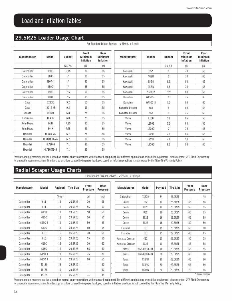
72
www.titan-intl.com
Load and Inflation Tables
Manufacturer Model BucketFront
Minimum Inflation
rear Minimum Inflation
Cu. Yd. psi psi
Caterpillar 980C 6.75 80 65
Caterpillar 980F 7 80 65
Caterpillar 980F-II 7 80 65
Caterpillar 980G 7 85 65
Caterpillar 980H 7.5 90 65
Caterpillar 980K 7.5 85 65
Case 1221E 9.2 55 65
Case 1221E XR 9.2 55 65
Doosan DL500 6.8 75 65
Furukawa FL460 6.0 75 65
John Deere 844J 7.25 85 65
John Deere 844K 7.25 85 65
Hyundai HL780-7A 6.7 75 65
Hyundai HL780XTD-7A 6.7 80 65
Hyundai HL780-9 7.1 80 65
Hyundai HL780XTD-9 7.1 85 65
29.5R25 Loader Usage ChartFor Standard Loader Service: < 250 ft, < 5 mph
Manufacturer Model BucketFront
Minimum Inflation
rear Minimum Inflation
Cu. Yd. psi psi
Kawasaki 95Z 6 70 65
Kawasaki 95ZII 6 70 65
Kawasaki 95ZIII 6.5 80 65
Kawasaki 95ZIV 6.5 75 65
Kawasaki 95ZV-2 7.25 80 65
Komatsu WA500-1 6 75 65
Komatsu WA500-3 7.2 80 65
Komatsu Dresser 555 6 80 65
Komatsu Dresser 558 6 75 65
Volvo L190 5.2 65 55
Volvo L190B 5.2 65 55
Volvo L220D 7 75 65
Volvo L220E 7.1 85 65
Volvo L220F 7.8 90 65
Volvo L220G 8.2 90 65
Pressure and ply recommendations based on normal quarry operations with standard equipment. For different applications or modified equipment, please contact OTR Field Engineering for a specific recommendation. Tire damage or failure caused by improper load, ply, speed, or inflation practices is not covered by the Titan Tire Warranty Policy.
Manufacturer Model payload Tire sizeFront
pressurerear
pressure
Caterpillar TS225 24 26.5R25 — 45
Deere 762 11 23.5R25 55 55
Deere 762B 11 23.5R25 55 55
Deere 862 16 26.5R25 65 65
Deere 862B 16 26.5R25 65 65
Deere 862B 16 29.5R25 50 50
Fiatallis 161 15 26.5R25 60 60
Fiatallis 161 15 29.5R25 45 45
Kumatsu Dresser 412 11 23.5R25 50 55
Kumatsu Dresser 412B 11 23.5R25 55 55
Kress 862-OB18-RD 18 29.5R25 55 55
Kress 862-OB20-RD 20 29.5R25 60 60
Terex TS14B 20 29.5R25 60 60
Terex TS14C 20 29.5R25 65 60
Terex TS14G 20 29.5R25 70 65
Manufacturer Model payload Tire sizeFront
pressurerear
pressure
Tons psi psi
Caterpillar 611 15 26.5R25 70 65
Caterpillar 611 15 29.5R25 55 50
Caterpillar 613B 11 23.5R25 50 50
Caterpillar 613C 11 23.5R25 50 50
Caterpillar 613C II 11 23.5R25 50 55
Caterpillar 613G 11 23.5R25 60 55
Caterpillar 615 16 26.5R25 70 60
Caterpillar 615 16 29.5R25 55 50
Caterpillar 615C 16 26.5R25 70 60
Caterpillar 615C 16 29.5R25 55 50
Caterpillar 615C II 17 26.5R25 75 70
Caterpillar 615C II 17 29.5R25 60 55
Caterpillar TS180 19 29.5R25 — 60
Caterpillar TS185 19 23.5R25 — 50
Caterpillar TS185 19 26.5R25 — 35
Radial Scraper Usage ChartsFor Standard Scraper Service: < 2.5 mi, < 30 mph
Pressure and ply recommendations based on normal quarry operations with standard equipment. For different applications or modified equipment, please contact OTR Field Engineering for a specific recommendation. Tire damage or failure caused by improper load, ply, speed or inflation practices is not covered by the Titan Tire Warranty Policy.
*
*
* * Towed scraper
*

73
800.USA.BEAR
Load and Inflation Tables
18.00R33 Rigid Truck Usage ChartFor Standard Earthmover Service: < 2.5 mi, < 30 mph
Payloads not to exceed vehicle rating
Manufacturer Model payloadFront
Minimum Inflation
rear Minimum Inflation
tons psi psi
Astra RD 40C 44 115 115
Caterpillar 769B 35 95 90
Caterpillar 769C 40 110 110
Caterpillar 769D 35 110 110
Caterpillar 770 40 120 115
Caterpillar 770F 49 115 115
Caterpillar 770G 50 115 120
Caterpillar 771C Quarry 44 120 120
Caterpillar 771D 45 120 120
Euclid-Hitachi EH 650 40 95 100
Euclid-Hitachi EH 700 42 115 115
Euclid-Hitachi EH 750 43 120 120
Euclid-Hitachi EH 750-3 46 120 120
Euclid-Hitachi R35 35 105 105
Euclid-Hitachi R36 40 95 100
Euclid-Hitachi R40 42 110 110
Euclid-Hitachi R40-C 42 115 115
Komatsu HD325-3 35 85 95
Komatsu HD325-5 35 85 95
Komatsu HD325-6 Quarry 44 115 120
Komatsu HD325-6 4WD 35 100 100
Komatsu HD325-6 44 105 115
Komatsu HD325-7 40 110 115
Komatsu HD405-7 45 120 120
Komatsu Haulpak 140M 40 110 110
Perlini DP 405 WD 44 115 115
Terex 3340 40 120 115
Pressure and ply recommendations based on normal quarry operations with standard equip-ment. For different applications or modified equipment, please contact OTR Field Engineering for a specific recommendation. Tire damage or failure caused by improper load, ply, speed, or inflation practices is not covered by the Titan Tire Warranty Policy.
24.00R35 Rigid Truck Usage ChartFor Standard Earthmover Service: < 2.5 mi, < 30 mph
Payloads not to exceed vehicle rating
Manufacturer Model payloadFront
Minimum Inflation
rear Minimum Inflation
tons psi psi
Caterpillar 773 50 75 70
Caterpillar 773B 58 80 80
Caterpillar 773D 50 80 85
Caterpillar 773E 60 90 90
Caterpillar 773F 60 95 90
Caterpillar 773F 57 100 90
Caterpillar 773G 54 80 85
Caterpillar 773G-4T 69 100 90
Caterpillar 775B Quarry 65 95 95
Caterpillar 775D 65 90 105
Caterpillar 775E 70 95 105
Caterpillar 775F 70 100 105
Caterpillar 775F 69 105 105
Caterpillar 775G 70 110 105
Caterpillar 775G-4T 79 110 105
Dart 2085 85 55 70
Euclid-Hitachi EH 1000 66 90 95
Euclid-Hitachi EH 1100 72 95 105
Euclid-Hitachi EH 1100-3 72 100 105
Euclid-Hitachi R50 58 80 80
Euclid-Hitachi R60 63 80 90
Euclid-Hitachi R60-C 66 105 90
Euclid-Hitachi R65 69 90 95
Euclid-Hitachi R65-C 71 95 105
Euclid-Hitachi R75 75 110 105
Komatsu HD465-3 51 70 75
Komatsu HD465-5 61 70 80
Komatsu HD465-5 Quarry 66 95 105
Komatsu HD465-7 61 85 95
Komatsu HD605-5 67 90 95
Komatsu HD605-7 69 100 105
Komatsu-Haulpak 210M 60 85 85
Perlini DP705 WD 72 100 105
Terex 3308E 55 80 80
Terex 3309 55 85 90
Terex 3310E 66 95 95
Terex TR60 60 90 85
Terex TR70 72 110 105
CT - Contact Titan Technical Services Pressure and ply recommendations based on normal quarry operations with standard equipment. For different applications or modified equipment, please contact OTR Field Engineering for a specific recommendation. Tire damage or failure caused by improper load, ply, speed, or inflation practices is not covered by the Titan Tire Warranty Policy.

74
www.titan-intl.com
Load and Inflation Tables
27.00R49 Rigid Truck Usage ChartFor Standard Earthmover Service: < 2.5 mi, < 30 mph
Payloads not to exceed vehicle rating
Manufacturer Model payloadFront
Minimum Inflation
rear Minimum Inflation
tons psi psi
Caterpillar 777 85 80 80
Caterpillar 777B 95 90 90
Caterpillar 777C 95 90 90
Caterpillar 777D 100 100 105
Caterpillar 777F 100 105 105
Caterpillar 777G 100 105 105
Euclid-Hitachi R85B 85 90 90
Euclid-Hitachi R90 96 90 95
Euclid-Hitachi R90C 100 95 100
Euclid-Hitachi R100 100 100 105
Euclid-Hitachi EH1600 100 100 105
Euclid-Hitachi EH1700 108 110 110
Euclid-Hitachi EH1700-3 100 105 105
Komatsu HD785-1 86 80 80
Komatsu HD785-3 86 85 90
Komatsu HD785-3 100 90 100
Komatsu HD785-5 106 105 110
Komatsu HD785-7 100 100 110
Komatsu Haulpak 325M 95 95 90
Komatsu Haulpak 330M 100 95 105
Komatsu Mining Systems HD785-5 106 105 110
Komatsu Mining Systems 330M 100 105 110
Kress CH160 160 CT 105
Kress CH180 180 CT CT
Perlini DP905 105 100 100
Rimpull RD100 100 90 100
Rimpull RD100C 100 95 105
Terex 3311C 85 80 80
Terex 3311D 77 90 80
Terex 3311E 94 100 90
Terex TR100 100 100 100
Terex TR100 (HR) 94 100 100
Unit Rig Dart 3100 100 100 100
Unit Rig Dart 4160 160 65 95
Unit Rig M85 85 80 80
Unit Rig M100 100 95 95
Unit Rig M120-15 120 110 110
Unit Rig Mark 24 85 95 80
Pressure and ply recommendations based on normal quarry operations with standard equip-ment. For different applications or modified equipment, please contact OTR Field Engineering for a specific recommendation. Tire damage or failure caused by improper load, ply, speed, or inflation practices is not covered by the Titan Tire Warranty Policy.
Above Loads are applicable to 30R56.5 tire
33.00R51 Rigid Truck Usage ChartFor Standard Earthmover Service: < 2.5 mi, < 30 mph
Payloads not to exceed vehicle rating
Manufacturer Model payloadFront
Minimum Inflation
rear Minimum Inflation
tons psi psi
Belaz 75137NA 150 110 110
Caterpillar 785D 157 115 115
Komastu HD1500-7 159 110 115
Pressure and ply recommendations based on normal quarry operations with standard equipment. For different applications or modified equipment, please contact OTR Field Engineering for a specific recommendation. Tire damage or failure caused by improper load, ply, speed, or inflation practices is not covered by the Titan Tire Warranty Policy.
37.00R57 Rigid Truck Usage ChartFor Standard Earthmover Service: < 2.5 mi, < 30 mph
Payloads not to exceed vehicle rating
Manufacturer Model payloadFront
Minimum Inflation
rear Minimum Inflation
tons psi psi
CAT 789C 195 105 110
CAT 789D 200 110 110
Euclid-Hitachi EH3500AC11 185 95 110
Komatsu 730E 203 110 110
Terex MT 3700 205 110 120
Pressure and ply recommendations based on normal quarry operations with standard equipment. For different applications or modified equipment, please contact OTR Field Engineering for a specific recommendation. Tire damage or failure caused by improper load, ply, speed, or inflation practices is not covered by the Titan Tire Warranty Policy.
40.00R57 Rigid Truck Usage ChartFor Standard Earthmover Service: < 2.5 mi, < 30 mph
Payloads not to exceed vehicle rating
Manufacturer Model payloadFront
Minimum Inflation
rear Minimum Inflation
tons psi psi
Belaz 75302NA 243 110 110
Caterpillar 793D 240 110 115
Caterpillar 793F NR NR NR
Euclid Hitachi EH4000AC11 250 105 105
Komatsu 830E 244 115 115
Terex MT 3700 205 90 95
Terex MT 4400 260 115 115
Pressure and ply recommendations based on normal quarry operations with standard equipment. For different applications or modified equipment, please contact OTR Field Engineering for a specific recommendation. Tire damage or failure caused by improper load, ply, speed, or inflation practices is not covered by the Titan Tire Warranty Policy. NR - Not Recommended. Contact your Titan rep for a recommendation.

75
800.USA.BEAR
Load and Inflation Tables
46/90R57 Rigid Truck Usage ChartFor Standard Earthmover Service: < 2.5 mi, < 30 mph
Payloads not to exceed vehicle rating
Manufacturer Model payloadFront
Minimum Inflation
rear Minimum Inflation
tons psi psi
Belaz 75302NA 243 100 105
CAT 793F 250 105 105
Euclid Hitachi EH4000AC11 244.713 105 105
Komatsu 830E-AC 244 105 110
Terex MT 3700 205 85 90
Terex MT 4400 260 110 110
Pressure and ply recommendations based on normal quarry operations with standard equipment. For different applications or modified equipment, please contact OTR Field Engineering for a specific recommendation. Tire damage or failure caused by improper load, ply, speed, or inflation practices is not covered by the Titan Tire Warranty Policy.
53/80R63 Rigid Truck Usage ChartFor Standard Earthmover Service: < 2.5 mi, < 30 mph
Payloads not to exceed vehicle rating
Manufacturer Model payloadFront
Minimum Inflation
rear Minimum Inflation
tons psi psi
Euclid Hitachi EH5000AC11 320 105 105
Komatsu 930E-4 320 105 105
Komatsu 930E-4SE 320 105 110
Pressure and ply recommendations based on normal quarry operations with standard equipment. For different applications or modified equipment, please contact OTR Field Engineering for a specific recommendation. Tire damage or failure caused by improper load, ply, speed, or inflation practices is not covered by the Titan Tire Warranty Policy.
56/80R63 Rigid Truck Usage ChartFor Standard Earthmover Service: < 2.5 mi, < 30 mph
Payloads not to exceed vehicle rating
Manufacturer Model payloadFront
Minimum Inflation
rear Minimum Inflation
tons psi psi
Cat 795 AC 345 105 105
Komatsu 960E-1 360 105 105
Komatsu 960E-1K 360 105 105
Komatsu 960E-2 360 105 105
Komatsu 960E-2K 360 105 105
Liebherr T282C 400 110 110
Terex MT 5500 360 100 100
Pressure and ply recommendations based on normal quarry operations with standard equipment. For different applications or modified equipment, please contact OTR Field Engineering for a specific recommendation. Tire damage or failure caused by improper load, ply, speed, or inflation practices is not covered by the Titan Tire Warranty Policy.
59/80R63 Rigid Truck Usage ChartFor Standard Earthmover Service: < 2.5 mi, < 30 mph
Payloads not to exceed vehicle rating
Manufacturer Model payloadFront
Minimum Inflation
rear Minimum Inflation
tons psi psi
Belaz 7561 400 105 105
CAT 795F AC 345 95 100
CAT 797F 400 110 110
Liebherr T282C 400 105 105
Terex MT 5500 360 90 90
Terex MT 6300 400 105 105
Pressure and ply recommendations based on normal quarry operations with standard equipment. For different applications or modified equipment, please contact OTR Field Engineering for a specific recommendation. Tire damage or failure caused by improper load, ply, speed, or inflation practices is not covered by the Titan Tire Warranty Policy.

76
www.titan-intl.com
Load and Inflation Tables
35/65R33 Loader Usage ChartsFor Standard Loader Service: < 250 ft, < 5 mph
Pit Loader Type Operation
Manufacturer Modelstandard Bucket size
Front Minimum Inflation
rear Minimum Inflation
Cu. Yd. psi psiCaterpillar 988B 8.25 100 65Caterpillar 988F 7.75 100 60Caterpillar 988G 8 105 65Caterpillar 988H 8.33 110 70Caterpillar 988H (BH) - 140 90Caterpillar 988H (BH) - 130 80Caterpillar 988H 8.4 110 70Kawasaki 110Z 7.5 90 60Kawasaki 110ZII 7.5 90 60Kawasaki 115ZIII 7.5 90 60Kawasaki 115ZIV 7.5 95 60Kawasaki 115ZIV-2 8.25 105 65Kawasaki 115ZV-2 8.3 100 65Kawasaki 115ZV-2 HL 6.5 90 60Komatsu WA600-1 7.1 85 60Komatsu WA600-3 8 95 60Komatsu WA600-6 8.4 110 70
Komatsu Dresser 568 7.5 90 60O&K 7500 7 85 60Terex 90C 9 100 65Volvo L320 8 100 60Volvo L330C 9 105 65Volvo L330D 9 105 65Volvo L330E 9 105 65Volvo L350F 10 120 75
Yard Loader Type Operations
Manufacturer Modelstandard Bucket size
Front Minimum Inflation
rear Minimum Inflation
Cu. Yd. psi psiCaterpillar 988B 8.25 90 60Caterpillar 988F 7.75 85 60Caterpillar 988G 8 95 60Caterpillar 988H 8.33 95 60Caterpillar 988H 9.2 95 60Kawasaki 110Z 7.5 80 60Kawasaki 110ZII 7.5 80 60Kawasaki 115ZIII 7.5 80 60Kawasaki 115ZIV 7.5 85 60Kawasaki 115ZIV-2 8.25 90 60Kawasaki 115ZV 7.5 85 60Kawasaki 115ZV-2 8.3 85 60Kawasaki 115ZV-2 HL 6.5 80 60Komatsu WA600-1 7.1 75 60Komatsu WA600-3 8 80 60Komatsu WA600-6 8.4 95 60
Komatsu Dresser 568 7.5 80 60O&K 7500 7.0 75 60Terex 90C 9 85 60Volvo L320 8 85 60Volvo L330C 9 90 60Volvo L330D 9 90 60Volvo L330E 9 90 60Volvo L330F 10.1 100 60
For Service under chains, or load and carry operations, contact OTR Field Engineering. Pressure recommendations based on normal quarry operations with standard equipment. For different applications or modified equipment, please contact OTR Field Engineering for a specific recommendation. Tire damage or failure caused by improper load, ply, speed, or inflation practices is not covered by the Titan Tire Warranty Policy. For the Block Handler Arrangement (BH) pressure recommendation is subject to change based on actual applications. For the Block Handler Arrangement (BH) theThe load and cold inflation pressure imposed on the rim and wheel must not exceed the rim and wheel manufacturer’s recommendation even though the tire may be approved for a higher load or inflation. Rims and wheels may be identified with a maximum load and maximum cold inflation rating. For rims and wheels not so identified or for service conditions exceeding the rated capacities, consult the rim and wheel manufacturer to determine rim and wheel capacities for the intended service.
45/65R45 Loader Usage ChartFor Standard Loader Service: < 250 ft, < 5 mph
For L-4, L-5, L-5S and L-5/L-5S
Manufacturer Model standard Bucket size
Front Minimum Inflation
rear Minimum Inflation
Cu. Yd. psi psi)Caterpillar 854K Dozer 33-58 70 60Caterpillar 992B 10 75 60Caterpillar 992C 12.5 100 65Caterpillar 992C HL 12.5 105 70Caterpillar 992D 14 105 65Caterpillar 992D HL 14 110 70Caterpillar 992G 16 120 75Caterpillar 992G HL 16 120 75Caterpillar 992K 14 120 75Caterpillar 992K 14 110 70Caterpillar 992K HL 14 120 75Caterpillar 992K HL 14 105 65Komatsu WA800-2 13.7 100 65Komatsu WA800-3 14.4 105 70Komatsu WA900-3 17 115 75
LeTourneau L1000 17 115 75
For Service under chains, or load and carry operations, contact OTR Field Engineering for Aralon belted options. Pressure and ply recommendations based on normal quarry operations with standard equipment. For different applications or modified equipment, please contact OTR Field Engineering for a specific recommendation. Tire damage or failure caused by improper load, ply, speed, or inflation practices is not covered by the Titan Tire Warranty Policy.
HL - High Lift, extended booms, etc.

77
800.USA.BEAR
Load and Inflation Tables
50/65R51 Loader Usage ChartFor Standard Loader Service: < 250 ft, < 5 mph
Manufacturer Model standard Bucket size
Front Minimum Inflation
rear Minimum Inflation
Cu. Yd. psi psiCaterpillar 993K 17 115 75Caterpillar 993K HL 17 120 80Caterpillar 993K HL 19 120 85
For Service under chains, or load and carry operations, contact OTR Field Engineering for Aralon belted options. Pressure and ply recommendations based on normal quarry operations with standard equipment. For different applications or modified equipment, please contact OTR Field Engineering for a specific recommendation. Tire damage or failure caused by improper load, ply, speed, or inflation practices is not covered by the Titan Tire Warranty Policy.
HL - High Lift, extended booms, etc.

78
www.titan-intl.com
Load and Inflation Tables
Off the Road Tire Loads - Use on Industrial Vehiclesply
ratingInflation pressure
psi (kpa)
load in pounds (kg) at various speeds mph (km/h)
stationary Creep 2.5 mph(4 km/h)
5 mph(10 km/h)
10 mph(15 km/h)
12.5 mph(20 km/h)
15 mph(25 km/h)
14.00-24/25
24123 33500 27300 24000 20900 19400 18500 17900
(850) (15200) (12400) (10900) (9500) (8800) (8400) (8100)
28134 35300 28700 25400 22000 20500 19400 18700
(925) (16000) (13000) (11500) (10000) (9300) (8800) (8500)
16.00-25 32127 44100 35900 31700 27600 25600 24300 23400
(875) (20000) (16300) (14400) (12500) (11600) (11000) (10600)
18.00-25 40138 60000 48700 43200 37500 34800 33100 32000
(950) (27200) (22100) (19600) (17000) (15800) (15000) (14500)
18.00-33 40138 70500 57300 50700 44000 41000 38800 37500
(950) (32000) (26000) (23000) (20000) (18600) (17600) (17000)
21.00-25 40120 72800 59100 52200 45400 42300 39900 38600
(825) (33000) (26800) (23700) (20600) (19200) (18100) (17500)
21.00-35 42123 85800 69700 61500 53600 49800 47200 45600
(850) (38900) (31600) (27900) (24300) (22600) (21400) (20700)
Industrial Vehicle for use on Smooth Floors and Runways Onlyply
ratingInflation pressure
psi (kpa)
load in pounds (kg) at various speeds mph (km/h)
stationary Creep 2.5 mph(4 km/h)
5 mph(10 km/h)
10 mph(15 km/h)
12.5 mph(20 km/h)
15 mph(25 km/h)
14.00-24/25
24145 37700 36800 32600 27600 26500 25800 25600
(1000) (17100) (16700) (14800) (12500) (12000) (11700) (11600)
28145 37700 36800 32600 27600 26500 25800 25600
(1000) (17100) (16700) (14800) (12500) (12000) (11700) (11600)
16.00-25 32145 49600 48300 42800 36200 34800 34000 33500
(1000) (22500) (21900) (19400) (16400) (15800) (15400) (15200)
18.00-25 40145 67500 63500 56400 47600 45900 44800 44100
(1000) (30600) (28800) (25600) (21600) (20800) (20300) (20000)
18.00-33 40145 79400 73400 65300 55100 53100 51800 50900
(1000) (36000) (33300) (29600) (25000) (24100) (23500) (23100)
21.00-25 40144 81800 81800 72800 61300 59100 57800 56900
(990) (37100) (37100) (33000) (27800) (26800) (26200) (25800)
21.00-35 42145 96300 96300 85800 72300 69700 68100 67000
(1000) (43700) (43700) (38900) (32800) (31600) (30900) (30400)
IMPORTANT: Loads shown in the above tables. The rim manufacturer must be consulted to determine the suitability of the rim/wheel for the intended service. .Industrial vehicles consist of vehicles such as counterbalanced lift trucks, container handlers, straddle carriers, aircraft tow tractors, pavers, mobile crushers, log stackers and rough terrain fork lifts.
Creep is defined as movement at very slow speed, not over 200’ (60 m) in 30 minutes. During creep motion loads on tires are very high. Consideration must be given to the type of surface over which the equipment is travelling.
Smooth floors and runways are defined as paved or protected surfaces which are free of undulations, obstructions or discontinuities.
Loads shown above are for the tires only. The rim manufacturer must be consulted to determine the suitability of the rim/wheel for the intended service.

79
800.USA.BEAR
Load and Inflation Tables
Tire Size Speed mphTIRE LOAD LIMITS (LBS.) AT VARIOUS COLD INFLATION PRESSURES (PSI)
10 15 20 25 30 35 40 45 50 55 60 65 70 75 80 85 90
66x44.00-25NHS
30 6,000 7600 (6) 9,100 10,200 11,400 12,800 13600 (16) 14,300 15700 (20) ---- ---- ----20 6,700 8,500 10,200 11,400 12,800 14,300 15,200 16,000 17,600 ---- ---- ----10 7,900 10,000 12,000 13,500 15,000 16,900 18,000 18,900 20,700 ---- ---- ----5 9,500 12,000 14,400 16,100 18,000 20,200 21,500 22,600 24,800 ---- ---- ----
Creep 12,000 15,200 18,200 20,400 22,800 25,600 27,200 28,600 31,400 ---- ---- ----Stationary 15,900 20,100 24,100 27,000 30,200 33,900 36,000 37,900 41,600 ---- ---- ----
68x50.00-32NHS
30 5,840 7,400 8,800 9,900 11,000 12300 (16) 13,200 14300 (20) ---- ---- ---- ----20 6,550 8,300 9,850 11,100 12,300 13,800 14,800 16,000 ---- ---- ---- ----10 7,700 9,750 11,600 13,100 14,500 16,200 17,400 18,900 ---- ---- ---- ----5 9,250 11,700 13,900 15,600 17,400 19,400 20,900 22,600 ---- ---- ---- ----
Creep 11,700 14,800 17,600 19,800 22,000 24,600 26,400 28,600 ---- ---- ---- ----Stationary 15,500 19,600 23,300 26,200 29,200 32,600 35,000 37,900 ---- ---- ---- ----
66x43.00-25NHS
30 5,840 7,400 8,800 9900 (10) 11000 (12) 12300
(14)13200 (16) 13900 14800
(20) ---- ---- ----
20 6,550 8,300 9,850 11,100 12,300 13,800 14,800 15,600 16,600 ---- ---- ----10 7,700 9,750 11,600 13,100 14,500 16,200 17,400 18,400 19,600 ---- ---- ----5 9,250 11,700 13,900 15,600 17,400 19,400 20,900 21,960 22,000 ---- ---- ----
Creep 11,700 14,800 17,600 19,800 22,000 24,600 26,400 27,800 29,600 ---- ---- ----Stationary 15,500 19,600 23,300 26,200 29,200 32,600 35,000 36,800 39,200 ---- ---- ----
66x43.00-26NHS
30 5,840 7,400 8,800 9,900 11,000 12000 (14) ---- ---- ---- ---- ---- ----
20 6,550 8,300 9,850 11,100 12,300 13,400 ---- ---- ---- ---- ---- ----10 7,700 9,750 11,600 13,100 14,500 15,800 ---- ---- ---- ---- ---- ----5 9,250 11,700 13,900 15,600 17,400 19,000 ---- ---- ---- ---- ---- ----
Creep 11,700 14,800 17,600 19,800 22,000 24,000 ---- ---- ---- ---- ---- ----Stationary 15,500 19,600 23,300 26,200 29,200 31,800 ---- ---- ---- ---- ---- ----
67x34.00-25NHS
30 5,840 7,400 8,800 10,200 11400 (10) 12,300 13200 (14) ---- ---- ---- ---- ----
20 6,550 8,300 9,850 11,400 12,800 13,800 14,800 ---- ---- ---- ---- ----10 7,700 9,750 11,600 13,500 15,000 16,200 17,400 ---- ---- ---- ---- ----5 9,250 11,700 13,900 16,100 18,000 19,400 20,900 ---- ---- ---- ---- ----
Creep 11,700 14,800 17,600 20,400 22,800 24,600 26,400 ---- ---- ---- ---- ----Stationary 15,500 19,600 23,300 27,000 30,200 32,600 35,000 ---- ---- ---- ---- ----
67x34.00-26NHS
30 5,840 7,400 8,800 9,900 11,000 12,000 13200 (14) ---- ---- ---- ---- ----20 6,550 8,300 9,850 11,100 12,300 13,400 14,800 ---- ---- ---- ---- ----10 7,700 9,750 11,600 13,100 14,500 15,800 17,400 ---- ---- ---- ---- ----5 9,250 11,700 13,900 15,600 17,400 19,000 20,900 ---- ---- ---- ---- ----
Creep 11,700 14,800 17,600 19,800 22,000 24,000 26,400 ---- ---- ---- ---- ----Stationary 15,500 19,600 23,300 26,200 29,200 31,800 35,000 ---- ---- ---- ---- ----
DH73x44.00-32
30 6,800 8,550 10,200 11,700 12,800 (12) 14,300 15200 (16) ---- ---- ---- ---- ----20 7,600 9,600 11,400 13,100 14,300 16,000 17,000 ---- ---- ---- ---- ----10 9,000 11,300 13,500 15,400 16,900 18,900 20,100 ---- ---- ---- ---- ----5 10,700 13,500 16,100 18,500 20,200 22,600 24,000 ---- ---- ---- ---- ----
Creep 13,600 17,100 20,400 23,400 25,600 28,600 30,400 ---- ---- ---- ---- ----Stationary 18,000 22,700 27,000 31,000 33,900 37,900 40,300 ---- ---- ---- ---- ----
DH73x50.00-32
30 6,950 8,800 10,500 12,000 13,200 14800 (16) ---- ---- ---- ---- ---- ----20 7,800 9,850 11,800 13,400 14,800 16,600 ---- ---- ---- ---- ---- ----10 9,150 11,600 13,900 15,800 17,400 19,500 ---- ---- ---- ---- ---- ----5 11,000 13,900 16,600 19,000 20,900 23,400 ---- ---- ---- ---- ---- ----
Creep 13,900 17,600 21,000 24,000 26,400 29,600 ---- ---- ---- ---- ---- ----Stationary 18,400 23,300 27,800 31,800 35,000 39,200 ---- ---- ---- ---- ---- ----
High Flotation Tires Used In Agricultural, Logging And Off-The-Road Service
Figures in parentheses denote ply ratings or load index for which loads and inflations are maximum.Creep speed is a travel rate of not over 200 feet in a 30 minute period.Inflation pressures for a ply rating are constant at any speed. For variable or cyclic loading conditions contact your Titan representative at 515-265-9429.
NOTES: 1. The small index numbers denote ply rating for which accompanying loads and inflations are maximum. 2. For variable loading operations where loads increase or decrease, the load per tire when the vehicle is empty must be less
than 40% of the load on the tire when the vehicle is fully loaded. Maximum load may not be carried for more than one mile before unloading operation starts. Loading or unloading must be completed within one mile.
3. For operations at other speeds with no change in inflation pressure, the loads in the above table may be changed as follows:
MAXIMUMSPEED (mph)
% CHANGEIN LOADS
20 +12
10 +32
5 +58
*Creep +100
Stationary +165
Creep speed is a travel rate of not over 200 feet in a 30 minute period

80
www.titan-intl.com
High Flotation Tires Used in Agricultural, Logging and Off-the-Road ServiceTIRES USED AS SINGLES WITH NO SUSTAINED HIGH TORQUE
30 MPH TIRE LOAD LIMITS (LBS.) AT VARIOUS COLD INFLATION PRESSURES (PSI)
TIRE SIZE 6 9 12 15 17 20 23 26 29 32 35 38 41 44 46
1000/50R25 5360 6400 7400 8550 9650 (159) 1070 11700 (166) 12300 13200 13600 13900 (172) 14800 15200 16100 16500
(178)
1050/50R25 5840 6950 8050 9350 10500 (162) 11700 12800 (169) 13600 14300 14800 15200 (175) 16100 16500
(178)
1050/50R32 6400 7600 8800 10200 11400 (165) 12800 13900 (172) 14800 15700 16100 16500 (178)
1250/35R32 6000 7400 8550 9650 11000 (164) 12000 13200 (170) 14300 14800 15700 16100 (177)
1250/50R32 8550 10200 11700 13600 15200 (175) 17100 18700 (182) 19800 20400 (185) 21500 22000 (188)
1250/35R42 6800 8250 9650 11000 12300 (168) 13600 15200 (175) 16100 16500 (178) 17600 18200 (181)
NOTES: 1. For loads at other conditions see notes 1, 2 and 3 above. 2. The number in parentheses is tire’s load index.
Load and Inflation Tables
Radial Ply Terra
Diagonal (Bias) Ply Log Skidder Drive Wheel Tires Used in Logging or Forestry Service(other than on cable or grapple skidders) Tires Used as Singles
MAX SPEED 20 MPH (30 KM/H) - A6 TIRE LOAD LIMITS (LBS.) AT VARIOUS COLD INFLATION PRESSURES
TIRE SIZEpsikPa
20140
25170
30210
35240
40280
16.9-30lbs.kg
44002000
50802300
5680 (10)2575 (10) 141 6150
28006600 (14)3000 (14) 148
18.4-26lbs.kg
49402240
5680 (10)2575 (10) 141 6400 (12)
2900 (12) 145
18.4-30lbs.kg
53602430
60002725
6800 (12)3075 (12) 147
18.4-34lbs.kg
56802575
6400 (10)2900 (10) 145
23.1-26lbs.kg
7150 (10)3250 (10) 149 8250
37509100 (14)4125 (14) 157 9900 (16)
4500 (16) 160
24.5-32lbs.kg
88004000
9900 (12)4500 (12) 160 11000 (16)
5000 (16) 164 12000 (18)5450 (18) 167
28L-26lbs.kg
3250 (12)3750 (12) 164 9350 (14)
4250 (14) 158 10500 (16)4750 (16) 162 11400 (20)
5150 (20)
30.5L-32lbs.kg
10500 (12)4750 (12) 182 11700 (16)
5300 (16) 166 13200 (20)6000 (20) 170 14300
650015700 (26)7100 (26) 176
DH35.5L-32lbs.kg
13900 (16)6300 (16) 172 16100 (20)
7300 (20) 177 176008000
19300 (26)8750 (26) 183
NOTES: 1. Figures in (parentheses) denote ply rating or load range for which bold face loads and inflations are maximum. Numbers after ply ratings are Load Index numbers. 2. For shipping purposes, tire inflation pressure may be increased to 30 psi (210 kPa). Inflation pressure must be adjusted to correct operating pressure before skidder is removed from carrier.
Consult tire manufacturer for minimum tire shipping pressure. 3. “Tire Load Limit” for log skidders is defined as the maximum load for an individual tire due to the total radial forces imposed on the tire DURING OPERATION. This maximum load includes
total vehicle weight with accessories and weight transfer. For grapple and cable skidders, refer to the table below. 4. For load and carry type of logging operations such as loaders equipped with log forks and feller-bunchers, with
maximum speed of 5 mph (10 km/h), above tire load limits may be increased 50% with 5 psi (35 kPa) increase in inflation pressure. Maximum length of carry is 500 feet (150 m).
5. For cyclic loading service, see cyclic harvest table on page 46. 6. When used as duals, tire loads must be reduced. Multiply figures in table by .88. 7. Consult rim and wheel manufacturer for rims for this type of service. 8. For transport service and operations that do not require sustained high torque, the following load limits apply:
MAX SPEED % CHANGE IN LOADS CHANGE IN INFL. PRESSURE
STATIONARY +170% +5 PSI (30 KPA)
10 MPH (15 KM/H) +20 NONE
15 MPH (25 KM/H) +15 NONE
20 MPH (30 KM/H) NONE NONE
25 MPH (40 KM/H) -10 NONE
TIRE TYPE NOMENCLATURECODE NO. TIRE TYPE
LS-2 INTERMEDIATE TREADLS-3 DEEP TREAD

81
800.USA.BEAR
Load and Inflation Tables
Diagonal (Bias) Ply Log Skidder Drive Wheel Tires Used on Cable or Grapple Skidders Tires Used as Singles
MAX SPEED 5 MPH (10 KM/H) TIRE LOAD LIMITS (LBS.) AT VARIOUS COLD INFLATION PRESSURES
TIRE SIZEpsikPa
25170
30210
35240
40*275/280
45310
18.4-26 lbs.kg
69003120
7950 (10)3600 (10)
8950 (12)4060 (12)
18.4-34 lbs.kg
79503600
8950 (10)4060 (10)
23.1-26 lbs.kg
10000 (10)4540 (10)
116005260
12700 (14)5760 (14)
13900 (16)6300 (16)
24.5-32 lbs.kg
123005580
13900 (12)6300 (12)
15400 (16)7000 (16)
16800 (18)7600 (18)
Low Section Height
28L-26 lbs.kg
11600 (12)5260 (12)
13100 (14)5940 (14)
14700 (16)6650 (16)
16000 (20)10000 (20)
30.5L-32 lbs.kg
14700 (12)6650 (12)
16400 (16)7450 (16)
18500 (20)8400 (20)
200009000
22000 (26)10000 (26)
DH35.5L-32 lbs.kg
19500 (16)8850 (16)
22500 (20)10200 (20)
2465011200
27000 (26)12150 (26)
NOTES:1. Figures in (parentheses) denote ply rating or load range for which bold face loads and inflations are maximum. Numbers after ply ratings are Load Index numbers.2. For shipping purposes, tire inflation pressure may be increased to 30 psi (210 kPa). Inflation pressure must be adjusted to correct operating pressure before skidder is removed from carrier. Consult tire
manufacturer for minimum tire shipping pressure.3. “Tire Load Limit” for log skidders is defined as the maximum load for an individual tire due to the total radial forces imposed on the tire DURING OPERATION. This maximum load includes total vehicle weight
with accessories, plus load increases due to log winching or grappling loads and weight transfer.4. The table at left applies only to log skidder tires used on cable or grapple skidders with a maximum speed of 5 mph (10 km/h). For use on other types of logging or forestry equipment or at speeds greater
than 5 mph (10 km/h) refer to the table at the top of this page.5. When used as duals, tire loads must be reduced. Multiply figures in table by .88.6. Consult rim and wheel manufacturer for rims for this type of service.

82
www.titan-intl.com
Load and Inflation Tables
Material Handling Loads
Size
Service Condition Application SpeedCounterbalanced Lift Truck Industrial Vehicle Loads
Front/Drive Rear/Steer Smooth Floor Only Other Than Smooth Floor
Ply Rating
Catalog Number PSI (bar)
up to 10 mph (15 km/h)
up to 15 mph (25 km/h)
5 mph (10 km/h)
10 mph (15 km/h)
5 mph (10 km/h)
10 mph (15 km/h)
lbs. (kg) lbs. (kg) lbs. (kg) lbs. (kg) lbs. (kg) lbs. (kg)
Titan T4032x12-15 NHS 20 44P226 145 13,400 10,200 10,200 8,050 9,150 7,25035x15-15 NHS 24 44P376 150 17,950 13,655 13,655 10,790 12,305 9,69535x15-15 NHS 28 44P377 150 17,950 13,655 13,655 10,790 12,305 9,695
Titan T4444x18-20 NHS 32 44T3K1 150 27,300 20,700 20,700 16,400 18,700 14,70042x21-22 NHS 32 44T3J5 145 33,300 25,300 25,300 20,000 22,800 18,000
Titan PWT7.00-12 NHS 12 44P212 125 5,995 4,555 4,555 3,595 4,100 3,2357.50-16 NHS 12 44P2K8 115 8,015 6,090 6,090 4,810 5,485 4,3308.25-15 NHS 12 44P231 105 8,680 6,595 6,595 5,210 5,935 4,6858.25-15 NHS 14 44P2D5 120 9,385 7,135 7,135 5,630 6,420 5,070250-15 NHS 16 4492H1 135 9,450 7,200 7,200 5,680 6,450 5,100250-15 NHS 18 44P2H2 150 10,100 7,650 7,650 6,050 6,900 5,440
28x12-15 NHS 20 44P262 150 10,800 8,200 8,200 6,500 7,400 5,82028x9-15 NHS 12 44P2B5 120 6,880 5,230 5,230 4,125 4,705 3,71528x9-15 NHS 14 44P2D3 140 7,530 5,720 5,720 4,515 5,150 4,06529x8-15 NHS 12 44P216 125 6,870 5,220 5,220 4,120 4,700 3,71032x12-15 NHS 20 44P226 145 13,400 10,200 10,200 8,050 9,150 7,25032x15-15 NHS 24 44P3G7 150 15,900 12,100 12,100 9,550 10,900 8,60036x11-15 NHS 16 44P2F9 115 12,290 9,340 9,340 7,375 8,405 6,63536x11-15 NHS 24 44P6F9 145 14,100 10,700 10,700 8,450 9,650 7,600
Titan Industrial Deep Tread (IDT)5.70/5.00-8 NHS 10 4542A1 150 2,790 2,120 2,120 1,675 1,905 1,5056.90/6.00-9 NHS 10 454204 125 3,715 2,820 2,820 2,230 2,540 2,000
6.50-10 NHS 10 454263 115 4,225 3,210 3,210 2,535 2,890 2,2807.50-10 NHS 12 454287 120 5,655 4,300 4,300 3,395 3,870 3,0557.00-12 NHS 12 454212 125 5,995 4,555 4,555 3,595 4,100 3,2357.00-12 NHS 14 4542D7 145 6,535 4,970 4,970 3,920 4,470 3,5307.50-15 NHS 12 454269 115 7,690 5,845 5,845 4,615 5,260 4,1508.25-15 NS 12 454231 105 8,680 6,595 6,595 5,210 5,935 4,685
8.25-15 NHS 14 4542D5 120 9,385 7,135 7,135 5,630 6,420 5,07029x8-15 NHS 12 454216 125 6,870 5,220 5,220 4,120 4,700 3,71030x8-15 NHS 12 454251 125 6,940 5,275 5,275 4,165 4,745 3,745
Titan Industrial Service5.70-8 NHS 6 40B206 90 2,070 1,570 1,530 1210 1,415 1,1155.70-8 NHS 8 40B208 120 2,445 1830 1,830 1445 1,675 1,320
Size
Service Condition Application Speed
Counterbalanced Lift Truck Industrial Vehicle Loads
Front/Drive Rear/Steer Smooth Floor Only Other Than Smooth Floor
Ply Rating
Catalog Number PSI (bar) up to 10 mph (15
km/h) lbs (kg)up to 15 mph (25
km/h) lbs (kg) PSI (bar) 5 mph (10 km/h) lbs (kg)
10 mph (15 km/h) lbs (kg) PSI (bar) 5 mph (10
km/h) lbs (kg)10 mph (15
km/h) lbs (kg)Titan PWT
9.00-20 NHS 12 44P218 95 11,800 8,950 104 10,600 10,200 87 7,850 6,8009.00-20 NHS 14 44P2E8 110 12,800 9,750 122 11,540 11,120 102 8,550 7,45010.00-20 NHS 16 44P2E9 115 14,910 11,330 131 13,750 13,250 109 10,200 8,85011.00-20 NHS 16 44P2E2 110 15,845 12,040 126 14,450 13,900 105 10,700 9,30012.00-20 NHS 18 44P2E3 115 18,600 14,100 131 17,300 16,650 109 12,800 11,15012.00-20 NHS 20 44P2A7 130 19,900 15,100 144 18,350 17,700 120 13,600 11,850
Titan TT47210.00-20 NHS 18 472224 130 16,000 12,200 148 14,850 14,300 123 11,000 9,57012.00-20 NHS 20 4722A7 130 19,900 15,100 144 18,350 17,700 120 13,600 11,850
IMPORTANT: Loads shown in the above tables. The rim manufacturer must be consulted to determine the suitability of the rim/wheel for the intended service. Industrial vehicles consist of vehicles such as counterbalanced lift trucks, container handlers, straddle carriers, aircraft tow tractors, pavers, mobile crushers, log stackers and rough terrain fork lifts. Creep is defined as movement at very slow speed, not over 200’ (60 m) in 30 minutes. During creep motion loads on tires are very high. Consideration must be given to the type of surface over which the equipment is travelling.Smooth floors and runways are defined as paved or protected surfaces which are free of undulations, obstructions or discontinuities.

S:1
800.USA.BEAR
Safety Information
WARNINGThe task of servicing tires and wheels can be extremely dangerous and should be performed by trained personnel only, using the correct tools and following specific procedures. Failure to heed this warning could lead to serious injury or death. Read and understand the “Safety Information” in this catalog. We urge that the following is mandatory read-ing for all those involved in the servicing of tires and wheels:
Department of Labor Occupation Safety and Health Administration (OSHA) 29 CFR part 1910.177, titled Servicing of Single Piece and Multi-piece Rim Wheels. NOTE: Single piece rims have a rim made out of a single piece of material as shown on page S:20 and multiple-piece rims have a loose flange or flanges and lock ring as depicted on pages S:20 and S:21.
Rubber Manufacturers Association, “Care and Service of Farm Tires”Rubber Manufacturers Association, “Care and Service of Off-the-Highway Tires”Rubber Manufacturers Association, “Care and Service of Highway Truck Tires”Rubber Manufacturers Association, “Demounting and Mounting” Procedure Wall Charts: Automobile and Light Truck Tires on Single piece Rims Truck Tires (Radial and Bias ply) Truck/Bus Tires Agricultural Tires
We have shown step by step procedures for the servicing of single piece, three piece and five piece rims with the emphasis on safety operations for these rims in this catalog. Information on other types of rims can be found in the above RMA publications or in the catalogs published by the rim manufacturer. This and any other safety related infor-mation in Titan’s catalog is issued as assistance to supervisory and operational personnel in the actual tire/rim service environment. The responsibility for implementation of this safety information rests with operational and supervisory personnel carrying out the actual service work. Read and fully understand all procedures before attempting tire/wheel servicing.
If you have any doubt about the correct, safe method of performing any step in the demounting, mounting, adding or removing fill, or inflating process STOP! Seek out expert assistance from a qualified person.
Wear protective gloves, footwear, safety glasses, hearing protection and head gear when servicing tires and wheels.
Further references explaining safety procedures can be found in literature published by the Rubber Manufacturers Association, Washington D.C.; the Tire Association of North America, Washington D.C.; the National Wheel and Rim Association, Jacksonville, FL; and OSHA, Washington D.C.
SAFETY FIRST!

S:2
www.titan-intl.com
Safety Information
IMPORTANT!THIS IS THE FIRST STEP IN ALL DEMOUNTING OPERATIONS
Always remove the valve core and exhaust all air from a single tire and from both tires of a dual assembly. Check the valve stem by running a piece of wire through the stem to make
sure it is not plugged.
READ AND FOLLOW SAFETY INSTRUCTIONS. FAILURE TO DO SO COULD RESULT IN SERIOUS INJURY.
Removing valve core from single piece wheel.
Running wire through the stem of an single piece wheel.

S:3
800.USA.BEAR
Safety Information
This symbol indicates a warning message.
Failure to heed warnings could lead to serious injury or death.
• The task of servicing tires and wheels can be extremely dangerous and should be performed by trained person-nel only, using the correct tools, and following the pro-cedures presented here and in manufacturers’ catalogs, instruction manuals, or other industry and government instruction material.
• Several types of tire changing equipment are avail-able. Installers should be fully trained in correct operat-ing procedures and safety instructions for the specific machine being used. Always read and understand any manufacturer’s warning contained in the product litera-ture or posted on the equipment.
• Always use approved tire and rim combinations for sizes and contours.
• Always wear personal protection equipment such as gloves, footwear, eye protection, hearing protection and head gear, when servicing tire and wheels.
• Never exceed manufacturer’s recommended tire infla-tion pressure.
• Always use proper lifting techniques and mechanized lifting aids to move heavy components and assemblies.
GENERAL WARNINGS• Always take care when moving tires and wheels that
other people in the area are not endangered.
• Never leave a tire, wheel or assembly unsecured in a vertical position.
• Parts that are cracked, worn, pitted with corrosion or damaged must be destroyed, discarded and replaced with good parts.
• Always exhaust all air from the tire prior to demounting.
• Never try to repair wheel, rim or tire component parts. Replace all damaged, worn or suspect parts with good parts.
• Never reinflate a tire that has lost air pressure or has been reinflated without determining and correcting its problem.
• When conducting routine tire inspections also conduct a visual inspection of wheel and rim components. Always correct any non-conformities found.
• Always use restraining devices (safety cages) when inflating tires.
• Never exceed 35 psi when seating beads.
• Misapplication, improper inflation, overloading and ex-ceeding maximum speed may cause tire failure.
• Always inspect both sides of the tire to assure proper bead seat.

S:4
www.titan-intl.com
Safety Information
WARNING15.3” DIAMETER: 9” WIDTH EUROPEAN RIMSCertain European implement equipment has been imported into North America with unique diameter rims for which no North American produced replace-ment tire sizes are available.
Any attempt to mount and inflate 15” nominal bead diameter tires on these rims may ultimately cause one of the tire beads to break, possibly resulting in serious physical injury or even death.
The rims in question are 15.3” in diameter and 9” wide. However, rims manufactured in 1981 and earlier are marked as 15” diameter; only those manufactured in 1982 and 1983 are marked as 15.3” diameter. The key to avoiding this potentially dangerous situation is the 9” width. The U.S.A. (or Canada) wheel industry does not manufacture a 9” width rim for implement use.
The European tires sizes that may be mounted on these rims are:
10.0/75 – 15.3 (or 15)10.5/85 – 15.311.5/80 – 15.3 (or 15)12.5/80 – 15.3
U.S.A. (OR CANADA) PRODUCED IMPLEMENT TIRES ARE NOT TO BE MOUNTED ON ANY 9” WIDE IMPLEMENT RIM.
GENERAL WARNINGS
WARNINGThere is a danger of serious injury or death if a tire of one bead diameter is installed on a rim or wheel of a different rim diameter.
Always replace a tire with another tire of exactly the same bead diameter designation and suffix letters. For example: A 16” tire goes on a 16” rim. Never mount a 16” tire on a 16.1” or 16.5” rim. A 16.5” tire goes on a 16.5” rim. Never mount a 16.5” tire on a 16” or 16.1” rim.
While it is possible to pass a 16” diameter tire over the lip or flange of a 16.1” or 16.5” size diameter rim, it cannot be inflated enough to position itself against the rim flange. If an attempt is made to seat the tire bead by inflating, the tire bead will break with explosive force and could cause serious injury or death.
Rims of different diameters and tapers cannot be interchanged. The following diagram illustrates the difference between rims of two different tapers and diameters:
The following diagram shows how beads of a 16” tire will not seat on a 16.5” rim. The beads cannot be forced out against the rim flanges by using more air pressure be-cause this will break the beads and the tire will explode with force sufficient to cause serious injury or death.

S:5
800.USA.BEAR
Safety Information
GENERAL WARNINGS
TO DETERMINE COMPATIBLE RIM WIDTH FOR TIRE SIZES
NEVER stand, lean or reach over the assembly during inflation.
Determine the vehicle’s actual rim width by measuring, in inches, the distance between the vertical bead flanges as shown. A simple ruler or yardstick may be used, as rims are manufactured in half inch increments of width.
Find permissible replacement tire sizes in RMA’s Care and Service Tires Manual (Washington, D.C.). Most tires will fit on more than one rim width.
WARNINGSTAY OUT OF THE TRAJECTORY AS INDICATED BY SHADED AREA. ALWAYS USE A SAFETY CAGE OR OTHER RESTRAINING DEVICE IN COMPLIANCE WITH OSHA REGULATIONS.
Note: Under some circumstances, the trajectory may deviate from its expected path.

S:6
www.titan-intl.com
Safety Information
Tools Required: Cap and core removal tools, bead un-seating tool, two 36” tire irons, two 18” tire irons, veg-etable-based lubricant.
If you have any doubt about the correct, safe method of performing any step in the demounting,
mounting, adding or removing fill, or inflating process STOP! Seek out expert assistance from a qualified per-son.
Due to the variety of vehicle/equipment configura-tions and the range of conditions and situations
under which on-vehicle demounting (wheel/tire assembly still attached to vehicle or equipment) can occur, proper procedures for blocking, jacking, cribbing of the vehicle/ equipment must be done in accordance with the manu-facturers operator’s manual, maintenance manual or the information as provided by the vehicle/equipment manu-facturer.
Tools required: Jack, cribbing, blocking or other items as needed to jack and block the vehicle/equipment per the manufacturers instructions, hydraulic demounting tool, hooked tire iron, pry bar and lifting device or boom truck.1. Remove the fluid fill from the tire. Deflate the tire by removing the valve core housing. For tube-type tires, remove the rim nut and push the valve through the valve hole.
Always completely deflate tire (both tires of a dual assembly) by removing valve core(s) from valve(s)
before attempting any demounting operation. Check the valve stem by running a piece of wire through the stem to make sure it is not plugged.
Stand clear of trajectory danger zone when deflat-ing (page S:5).
Demounting Single Piece Wheel and Tire Assemblies (On-The-Vehicle)
Demounting tools apply pressure to rim flanges to unseat tire beads. Keep your fingers clear. Always
stand to one side when you apply hydraulic pressure.
3. Thoroughly lubricate the tire bead area and rim flange with a vegetable-based lubricant.
Never use a petroleum-based lubricant. Only use vegetable-based lubricant.
5. After the first section of the bead is over the rim flange, use one tire iron to pry the next section over the flange. Do not attempt to pry too large a section of the bead over the rim flange at one time. Continue prying tire over rim flange until the complete tire is on the outside of the rim flange.
2. After the tire is completely deflated, place a hydrau-lic “bead unseating” tool between the tire bead and rim flange and force the bead off the bead seat. Be careful not to damage the tire’s bead area. The beads should be unseated on both sides of the rim.
4. Lock the wheel with the valve at the top. At the bottom, force the outside bead into the well. At the top, insert long tire irons under the bead and pry the bead over the rim flange. Take small bites and avoid extremely hard prying, which will damage the tire bead.
Do not release your grip on either iron, as they may spring back.
Keep fingers clear of pinch points.

S:7
800.USA.BEAR
Safety Information
Tools Required: Cap and core removal tools, bead un-seating tool, two 36” tire irons, two 18” tire irons, veg-etable-based lubricant.
If you have any doubt about the correct, safe method of performing any step in the demounting,
mounting, adding or removing fill, or inflating process STOP! Seek out expert assistance from a qualified per-son.
Do not release your grip on either iron, as they may spring back.
Keep fingers clear of pinch points.
Demounting Single Piece Wheel and Tire Assemblies (On-The-Vehicle)
6. For tube-type tires, pull the tube out of the casing, starting at the bottom. If only the tube requires repair or replacement, this can be removed, repaired, and re-placed in the tire without removing the tire completely from the wheel. Before reinstalling the tube, thoroughly inspect the inside of the casing for damage or other foreign material. Remove any remaining fluid from inside the tire.
Tires or tubes with excessive or uneven wear, cracks, tears, punctures, blisters and or other dam-
age may explode during inflation or service. If tire or tube failure potential is suspected, destroy the tire and replace with known good tire or tube of correct size, type and manufacturer for assembly, machine, and application.
7. To remove the tire completely from the wheel, insert tire irons under the inside bead at the side of the tire. Pry the rest of the inside bead over the rim flange. When starting this operation, be sure that the bead area on the opposite side of the tire is down in the well of the rim.
Do not release your grip on either iron, as they may spring back.
Keep fingers clear of pinch points.

S:8
www.titan-intl.com
Safety Information
4. To put the tire on the wheel, place the inner bead over the flange at the top. Be sure the bead is not “hung up” on the bead seat, instead the bead is guided into the rim well, while the tire irons and/or rubber mallet are used to work the first bead over the rim. With the first bead on the rim, pull the tire toward the outside of the rim as far as possible to make room for the tube.
Keep fingers clear of pinch points.
Keep a firm grip on the tire iron(s), as they may spring back.
Mounting Single Piece Wheel and Tire Assemblies (On-The-Vehicle)
Tools Required: vegetable-based lubricant, wire brush, two 36” tire irons, two 18” tire irons, rubber mallet, exten-sion hose with in-line gauge and clip-on air chuck, air/wa-ter inflation gauge, restraining device.
If you have any doubt in the correct, safe method of performing any step in the demounting, mounting,
adding or removing fill, or inflating process STOP! Seek out expert assistance from a qualified person.
ALWAYS replace a tire on a rim with another tire of exactly the same rim diameter designation.
Rims of different diameters and tapers CANNOT be interchanged.
Remove water and foreign material from tire. Tubes or tires with excessive wear, cracks, tears, punc-
tures, blisters, or other damage may explode during inflation or service. If tube or tire failure potential is sus-pected, render the tube or tire unusable and replace with known good tube or tire.
Do not, under any circumstances, attempt to re-work, weld, heat, or braze any rim base or wheel
components.
3. Before placing tire on rim, be sure the rim’s valve hole is at the bottom of wheel. Also take care to ensure directional bead tires are mounted for correct rotation direction.
1. Thoroughly lubricate the tire bead area and rim flange with a vegetable-based lubricant.
Never use petroleum-based lubricant. Only use vegetable-based lubricant.
2. With a wire brush, clean and inspect rim for fatigue cracks. Replace any cracked, badly worn, damaged and severely rusted rims or wheels. Coat the rim with paint or a rust inhibitor if necessary.
Follow procedures and safety precautions of the paint manufacturer.
5. TubelesS:type tires, skip to step seven. For tube-type tires, be sure the valve is at the bottom of the wheel. Align the stem with the valve hole and starting at the bottom, place the tube in the tire. Place the valve in valve hole and screw the rim nut in place. Be sure that the tube is well inside the rim before proceeding to the next step.

S:9
800.USA.BEAR
Safety Information
10. Place a safety restraint over the rim and tire. Using an extension hose with an in-line air gauge and clip-on chuck (with valve core removed), inflate the tire to seat the beads. Do not exceed 35 psi. Check for correct con-centric centering of tire on rim.
For tubeless tires, successful mounting depends on how well the shape of the tire has been maintained. If the beads are in or near their molded position, they can be seated by inflating the tire, through the valve spud. Where the beads have been squeezed together, the use of an inflator ring (either horizontally or vertically) will be required to provide a seal between the tire bead and rim.
If assembly is incorrect, – STOP – DEFLATE – CORRECT THE ASSEMBLY – repeat procedure.
11. Raise the vehicle and rotate wheel assembly to have the valve at the top. If the tire is tube-type, completely deflate by removing the valve core housing to remove buckles and uneven stresses from the tube and flap before reinflation.
12. If assembly is correct, re-insert the valve core (for tube-type tires) and continue to inflate to recommend pressure.
If assembly is incorrect – STOP – DEFLATE – CORRECT THE ASSEMBLY – repeat procedure.
Stand clear of trajectory danger zone when inflating (page S:5).
Never inflate beyond manufacturer’s recommended tire pressure.
NOTE: A filter on the air inflation equipment to remove moisture from the airline prevents corrosion. Check the filter periodically to be sure it’s functioning properly.
Mounting Single Piece Wheel and Tire Assemblies (On-The-Vehicle)Tools Required: vegetable-based lubricant, wire brush, two 36” tire irons, two 18” tire irons, rubber mallet, exten-sion hose with in-line gauge and clip-on air chuck, air/wa-ter inflation gauge, restraining device.
If you have any doubt in the correct, safe method of performing any step in the demounting, mounting,
adding or removing fill, or inflating process STOP! Seek out expert assistance from a qualified person.
6. In tube-type tires, the tube should be partially inflated and areas that contact the rim should be relubricated to prevent localized stretching.
Never use petroleum-based lubricant. Only use vegetable-based lubricant.
Keep fingers clear of pinch points.
7. Starting at the top, use the tire irons to lift the outer bead up and over the rim flange, then down into the rim well. Be careful not to pinch the tube in this operation.
Keep fingers clear of pinch points.
Do not release your grip on either iron, as they may spring back.
8. After getting the first section of the outer bead into the rim well, remove the tire iron and place one hand against that section to hold it in then pry the remainder of the bead over the flange with the tire iron in the other hand.
Keep fingers clear of pinch points.
Keep firm grip on tire iron(s), as they may spring back.
9. With the valve stem at the bottom, lower the jack until the tire is centered on the rim. Centering of the tire and rim assembly is extremely important to prevent broken beads.

S:10
www.titan-intl.com
Safety Information
Demounting Single Piece Wheel and Tire Assemblies (Off-The-Vehicle)Tools Required: Cap and core removal tools, bead un-seating tool, vegetable-based lubricant, two 18” tire irons.
If you have any doubt in the correct, safe method of performing any step in the demounting, mounting,
adding or removing fill, or inflating process STOP! Seek out expert assistance from a qualified person.
1. Remove any fill from the tire. Completely deflate tire by removing valve core from valve before attempting any demounting operation. Check the valve stem by running a piece of wire through the stem to make sure it is not plugged. Lay the assembly on the floor with the narrow ledge on the bottom.
Stand clear of trajectory danger zone when deflat-ing (page S:5 & S:17).
3. With the narrow ledge on top, thoroughly lubricate the rim flange and tire bead area with a vegetable-based lubricant.
Never use petroleum-based lubricant. Only use vegetable-based lubricant.
2. Drive a bead unseating tool between the tire bead and rim flange, being careful not to damage the tire bead area. After the bead has been completely released around the tire, turn the tire and rim over and repeat the bead unseating procedure with the narrow ledge up.
Keep fingers clear of pinch points.
4. Force the part of the bead that is directly across from the valve into the well. Starting at the valve, pry the bead over the rim flange using two 18” long tire irons. Take small bites to avoid damaging the bead. Continue until the top bead is completely over the rim flange.
Keep a firm grip on tire irons as they may spring back.
Keep fingers clear of pinch points.
5. For tube-type tires, bring the assembly to an upright position and pull the tube out of the tire. If only the tube requires repair or replacement, this can be removed, re-paired, and replaced in the tire without removing the tire completely from the rim. Thoroughly inspect the inside of the casing for damage or other foreign material. Remove any remaining fluid from inside the tire.
Tire or tubes with excessive or uneven wear, cracks, tears, punctures, blisters or other damage
may explode during inflation or service. If tire or tube failure potential is suspected, destroy the tire and replace with known good tire or tube of correct size, type and manufacturer for assembly, machine, and application.

S:11
800.USA.BEAR
Safety Information
Demounting Single Piece Wheel and Tire Assemblies (Off-The-Vehicle)
Tools Required: Cap and core removal tools, bead un-seating tool, vegetable-based lubricant, two 18” tire irons.
If you have any doubt in the correct, safe method of performing any step in the demounting, mounting,
adding or removing fill, or inflating process STOP! Seek out expert assistance from a qualified person.
6. To completely remove the tire from the rim, turn as-sembly over so the narrow ledge is down and lubricate the second tire bead and rim flange. Be sure the bead still on the rim is in the rim well and insert the tire irons under the opposite side of the bead. Work the rim slowly out of the tire by taking small bites alternately using both tire irons.
Never use petroleum-based lubricant. Only use vegetable-based lubricant.
Keep a firm grip on the tire irons, as they may spring back.
Keep fingers clear of pinch points.
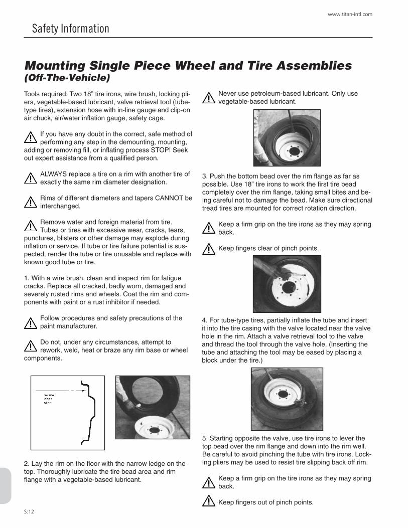
S:12
www.titan-intl.com
Safety Information
3. Push the bottom bead over the rim flange as far as possible. Use 18” tire irons to work the first tire bead completely over the rim flange, taking small bites and be-ing careful not to damage the bead. Make sure directional tread tires are mounted for correct rotation direction.
Keep a firm grip on the tire irons as they may spring back.
Keep fingers clear of pinch points.
Mounting Single Piece Wheel and Tire Assemblies (Off-The-Vehicle)
Tools required: Two 18” tire irons, wire brush, locking pli-ers, vegetable-based lubricant, valve retrieval tool (tube-type tires), extension hose with in-line gauge and clip-on air chuck, air/water inflation gauge, safety cage.
If you have any doubt in the correct, safe method of performing any step in the demounting, mounting,
adding or removing fill, or inflating process STOP! Seek out expert assistance from a qualified person.
ALWAYS replace a tire on a rim with another tire of exactly the same rim diameter designation.
Rims of different diameters and tapers CANNOT be interchanged.
Remove water and foreign material from tire. Tubes or tires with excessive wear, cracks, tears,
punctures, blisters or other damage may explode during inflation or service. If tube or tire failure potential is sus-pected, render the tube or tire unusable and replace with known good tube or tire.
1. With a wire brush, clean and inspect rim for fatigue cracks. Replace all cracked, badly worn, damaged and severely rusted rims and wheels. Coat the rim and com-ponents with paint or a rust inhibitor if needed.
Follow procedures and safety precautions of the paint manufacturer.
Do not, under any circumstances, attempt to rework, weld, heat or braze any rim base or wheel
components.
2. Lay the rim on the floor with the narrow ledge on the top. Thoroughly lubricate the tire bead area and rim flange with a vegetable-based lubricant.
Never use petroleum-based lubricant. Only use vegetable-based lubricant.
4. For tube-type tires, partially inflate the tube and insert it into the tire casing with the valve located near the valve hole in the rim. Attach a valve retrieval tool to the valve and thread the tool through the valve hole. (Inserting the tube and attaching the tool may be eased by placing a block under the tire.)
5. Starting opposite the valve, use tire irons to lever the top bead over the rim flange and down into the rim well. Be careful to avoid pinching the tube with tire irons. Lock-ing pliers may be used to resist tire slipping back off rim.
Keep a firm grip on the tire irons as they may spring back.
Keep fingers out of pinch points.

S:13
800.USA.BEAR
Safety Information
Mounting Single Piece Wheel and Tire Assemblies (Off-The-Vehicle)
Tools required: Two 18” tire irons, wire brush, locking pli-ers, vegetable-based lubricant, valve retrieval tool (tube-type tires), extension hose with in-line gauge and clip-on air chuck, air/water inflation gauge, safety cage.
If you have any doubt in the correct, safe method of performing any step in the demounting, mounting,
adding or removing fill, or inflating process STOP! Seek out expert assistance from a qualified person.
6. When the bead is well started, lubricate the remaining unmounted portion of the tire bead and rim flange. Taking small bites, spoon the tire bead over the rim flange until the final section drops over at the valve.
Never use petroleum-based lubricant. Only use vegetable-based lubricant.
Keep a firm grip on the tire irons as they may spring back.
Keep fingers out of pinch points.
7. Thoroughly lubricate the tire bead area and rim bead-seats on both sides of the tire.
Never use petroleum-based lubricant. Only use vegetable-based lubricant.
8. Centering of the tire and rim assembly is extremely important to prevent broken beads.
9. Place the tire in a safety cage. Using an extension hose with an in-line air gauge and clip-on chuck (with valve core removed), inflate the tire to seat the beads. Do not exceed 35 psi. Check for correct concentric centering of tire on rim. For tubeless tires, successful mounting depends on how well the shape of the tire has been maintained. If the beads are in or near their molded position, they can be seated by inflating the tire, through the valve spud. Where the beads have been squeezed together, the use of an inflator ring (either horizontally or
vertically) will be required to provide a seal between the tire bead and rim.
If assembly is incorrect – STOP – DEFLATE – CORRECT THE ASSEMBLY – repeat procedure.
10. If the tire is tube-type, completely deflate by removing the valve core housing to remove buckles and uneven stresses from the tube and flap before reinflation.
11. If assembly is correct, re-insert the valve core and continue to inflate to recommended pressure.
If assembly is incorrect – STOP – DEFLATE – CORRECT THE ASSEMBLY – repeat procedure.
Stand clear of trajectory danger zone when inflating (page S:5 & S:17).
Never inflate beyond manufacturer’s recommend-ed tire pressure.
NOTE: A filter on the air inflation equipment to remove moisture from the airline prevents corrosion. Check the filter periodically to be sure it’s functioning properly.
S:14
www.titan-intl.com
Safety Information
WARNINGThe task of servicing tires and wheels can be extremely dangerous and should be performed by trained personnel only, using the correct tools and following specific procedures. Failure to heed this warning could lead to serious injury or death. Read and understand the “Safety Information” in this catalog. We urge that the following is mandatory read-ing for all those involved in the servicing of tires and wheels:
Department of Labor Occupation Safety and Health Administration (OSHA) 29 CFR part 1910.177, titled Servicing of Single Piece and Multi-piece Rim Wheels. NOTE: Single piece rims have a rim made out of a single piece of material as shown on page S:20 and multiple-piece rims have a loose flange or flanges and lock ring as depicted on pages S:20 and S:21.
Rubber Manufacturers Association, “Care and Service of Farm Tires”Rubber Manufacturers Association, “Care and Service of Off-the-Highway Tires”Rubber Manufacturers Association, “Care and Service of Highway Truck Tires”Rubber Manufacturers Association, “Demounting and Mounting” Procedure Wall Charts: Automobile and Light Truck Tires on Single piece Rims Truck Tires (Radial and Bias ply) Truck/Bus Tires Agricultural Tires
We have shown step by step procedures for the servicing of single piece, three piece and five piece rims with the emphasis on safety operations for these rims in this catalog. Information on other types of rims can be found in the above RMA publications or in the catalogs published by the rim manufacturer. This and any other safety related infor-mation in Titan’s catalog is issued as assistance to supervisory and operational personnel in the actual tire/rim service environment. The responsibility for implementation of this safety information rests with operational and supervisory personnel carrying out the actual service work. Read and fully understand all procedures before attempting tire/wheel servicing.
If you have any doubt about the correct, safe method of performing any step in the demounting, mounting, adding or removing fill, or inflating process STOP! Seek out expert assistance from a qualified person.
Wear protective gloves, footwear, safety glasses, hearing protection and head gear when servicing tires and wheels.
Further references explaining safety procedures can be found in literature published by the Rubber Manufacturers Association, Washington D.C.; the Tire Association of North America, Washington D.C.; the National Wheel and Rim Association, Jacksonville, FL; and OSHA, Washington D.C.
SAFETY FIRST!

S:15
800.USA.BEAR
Safety Information
IMPORTANT!THIS IS THE FIRST STEP IN ALL DEMOUNTING OPERATIONS
Always remove the valve core and exhaust all air from a single tire and from both tires of a dual assembly prior to loosening the first rim clamp nut. Check the valve stem by running a
piece of wire through the stem to make sure it is not plugged.
READ AND FOLLOW SAFETY INSTRUCTIONS. FAILURE TO DO SO COULD RESULT IN SERIOUS INJURY.

S:16
www.titan-intl.com
Safety Information
This symbol indicates a warning message.
Failure to heed warnings could lead to serious injury or death.
• The task of servicing tires and wheels can be extremely dangerous and should be performed by trained personnel only, using the correct tools, and following the procedures presented here and in manufacturer’s catalogs, instruction manuals, or other industry and government instruction material.
• Always use approved tire and rim combinations for sizes and contours.
• Always wear personal protection equipment such as gloves, footwear, eye protection, hearing protection and head gear when servicing tire and wheel components.
• Never exceed manufacturer’s recommended tire inflation pressure.
• Always use proper lifting techniques and mechanized lifting aids to move heavy components and assemblies.
• Always take care when moving tires and wheels that other people in the area are not endangered.
• Never leave a tire, wheel or assembly unsecured in a vertical position.
• Parts that are cracked, worn, pitted with corrosion or damaged must be destroyed, discarded and replaced with good parts.
• Always exhaust all air from the tire prior to demounting.
• Never try to repair wheel, rim or tire component parts. Replace all damaged, worn or suspect parts with good parts.
• Never reinflate a tire that has lost air pressure or has been run flat without determining and correcting the problem.
• When conducting routine tire inspections also conduct a visual inspection of wheel and rim components. Always cor-rect any non-conformities.
• Always verify that part numbers and size designation of component parts are correctly matched for the assembly. See pages S:23 and S:24 for part number location.
• Always place wheel and tire assemblies in restraining devices when inflating tires. See page S:19, item 11.
GENERAL WARNINGS

S:17
800.USA.BEAR
Safety Information
Never stand, lean or reach across the potential tire and wheel component trajectory danger zones, as shown.
• Additional safety information can be found in literature published by the Rubber Manufacturer’s Association, Wash-ington, D.C.; The National Tire Dealer and Retreading Association, Washington, D.C.; The National Wheel and Rim Association, Jacksonville, FL.; and OSHA, Washington, D.C.
• Always completely deflate the tire (both tires of a dual tire assembly) by removing the valve core(s) from valve(s) before attempting any demounting or disassembling. Check the valve stem by running a piece of wire through the stem to make sure it is not plugged.
Note: Under some circumstances, the trajectory may deviate from its expected path. Always use a safety cage or other restraining device in compliance with OSHA regulations.
WARNINGSTAY OUT OF THE TRAJECTORY AS INDICATED BY SHADED AREA. ALWAYS USE A SAFETY CAGE OR OTHER RESTRAINING DEVICE IN COMPLIANCE WITH OSHA REGULATIONS.
Note: Under some circumstances, the trajectory may deviate from its expected path.
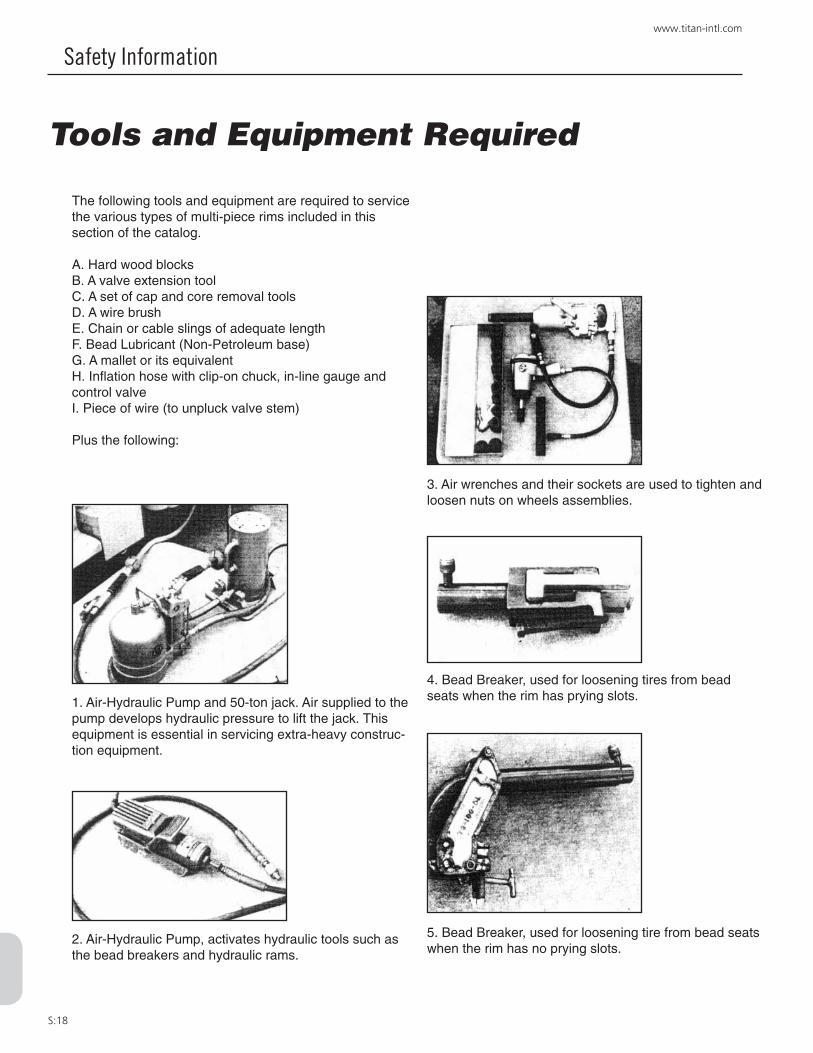
S:18
www.titan-intl.com
Safety Information
Tools and Equipment Required
The following tools and equipment are required to service the various types of multi-piece rims included in this section of the catalog.
A. Hard wood blocksB. A valve extension toolC. A set of cap and core removal toolsD. A wire brushE. Chain or cable slings of adequate lengthF. Bead Lubricant (Non-Petroleum base)G. A mallet or its equivalentH. Inflation hose with clip-on chuck, in-line gauge and control valveI. Piece of wire (to unpluck valve stem)
Plus the following:
1. Air-Hydraulic Pump and 50-ton jack. Air supplied to the pump develops hydraulic pressure to lift the jack. This equipment is essential in servicing extra-heavy construc-tion equipment.
2. Air-Hydraulic Pump, activates hydraulic tools such as the bead breakers and hydraulic rams.
3. Air wrenches and their sockets are used to tighten and loosen nuts on wheels assemblies.
4. Bead Breaker, used for loosening tires from bead seats when the rim has prying slots.
5. Bead Breaker, used for loosening tire from bead seats when the rim has no prying slots.

S:19
800.USA.BEAR
Safety Information
6. Top: 4” ram Hydraulic Demounting tool. Bottom: 6”-8” ram Hydraulic Demounting tool.
Rams apply pressure to the inside bead flange when removing tires from 15˚ tapered rims.
Gooseneck Tire Iron
Straight Tire Iron or Pry Bar
Hooked Tire Iron
7. Coffin hoist (1/2 ton capacity). This tool expands the bead on tapered bead seats, so that a tubeless tire will take air.
8. These tire irons are used to pry apart wheel compo-nents.
9. Mounting stand, used when mounting tires on rims that have been removed from a vehicle.
10. A service truck with a hydraulic hoist is essential to installing and removing today’s heavy off-the-road tires.
11. A cage of restraining device in which to place the wheel/tire assembly while inflating.
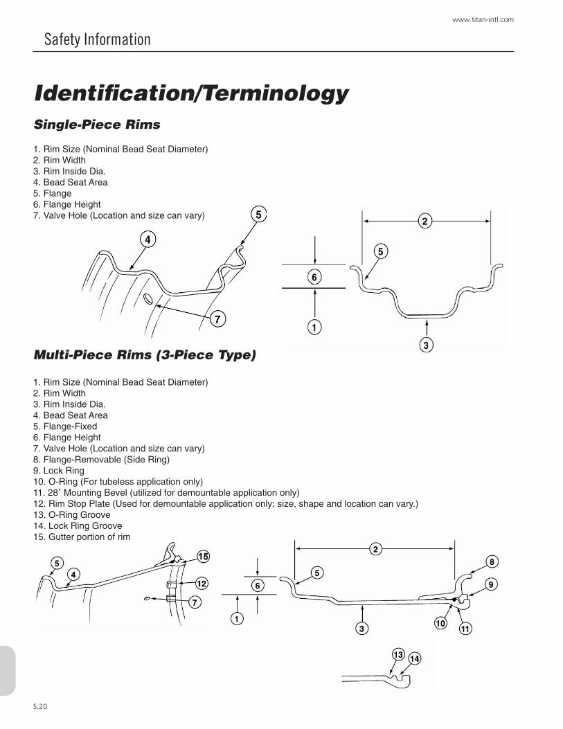
S:20
www.titan-intl.com
Safety Information
Identification/TerminologySingle-Piece Rims
1. Rim Size (Nominal Bead Seat Diameter)2. Rim Width3. Rim Inside Dia.4. Bead Seat Area5. Flange6. Flange Height7. Valve Hole (Location and size can vary)
Multi-Piece Rims (3-Piece Type)
1. Rim Size (Nominal Bead Seat Diameter)2. Rim Width3. Rim Inside Dia.4. Bead Seat Area5. Flange-Fixed6. Flange Height7. Valve Hole (Location and size can vary)8. Flange-Removable (Side Ring)9. Lock Ring10. O-Ring (For tubeless application only)11. 28˚ Mounting Bevel (utilized for demountable application only)12. Rim Stop Plate (Used for demountable application only; size, shape and location can vary.)13. O-Ring Groove14. Lock Ring Groove15. Gutter portion of rim

S:21
800.USA.BEAR
Safety Information
Identification/TerminologyMulti-Piece Rims (5-Piece Type)
1. Rim Size (Bead Seat Diameter)2. Rim Width3. Rim Inside Dia.4. Back Flange Portion of Rim Base5. Center Band Portion of Rim Base6. Gutter Band Portion of Rim Base7. Rim Base (Entire Shaded Area)8. Bead Seat Band (Removable, Gutter Side only)9. Lock Ring10. O-Ring11. Flange, Inner (Removable)12. Flange, Outer (Removable) *Note: Inner and Outer Flanges are identical13. 28˚ Mounting Bevel (Utilized for demountable application only)14. Valve Hole (Location, size and configuration can vary)15. Knurl (Located on Back Flange Portion of Rim Base and Bead Seat Band tire mating surfaces)16. O-Ring Groove17. Lock Ring Groove (size and shape can vary depending on style of lock ring)Not Shown: Pry Bar Pocket (continuous gap entire circumference on some items)

S:22
www.titan-intl.com
Safety Information
Identification/TerminologyMulti-Piece Rims (5-Piece Type)
1. Lock Ring2. Crimped on driver3. Notch in gutter portion of rim4. Notch in bead seat band
1. Driver Pocket (Welded on gutter portion of rim base)2. Driver Pocket (Welded on bead seat band)3. Driver Key*
*Note: See page S:24 for Driver Key Styles.
1. Gutter Portion of Rim Base2. 28˚ Mounting Bevel3. Rim Stop Plates (location, style and size can vary)
Crimped on Style Driver Loose Style Driver
Demountable Type Rims Valve Hole Styles
Straight Standard Inverted
Slot Tapped

S:23
800.USA.BEAR
Safety Information
NOTE: Gap not permitted
NOTE: Gap not permitted
Titan “W” Series Rims are not interchangeable with other types
If you have any doubt about the correct, safe method of performing any step in the demounting, mounting, or inflating process STOP! Seek assistance from a qualified person.
Rim and Wheel Components are not always interchangeable check part numbers carefully before assembling.
Titan’s “W” SERIES LOCK RINGS ARE NOT INTERCHANGEABLE WITH OTHER TYPES, it is vitally important that you must check part numbers carefully before rim assembly. Following is a summary of the changes.
“W” Style Lock Ring “W” Style Rim Base Bead Seat BandsA “W” appears after the part num-ber, which is stamped on the 45 degree face near the lock ring split (e.g. LR49W for a 49” rim), see il-lustration below.
A circumferential groove gives the ring a unique appearance. This lock ring can only be used with the new “W” style gutters.
There are two types of rim bases, the old version contains a “T” in the part number, whereas the new style contains a “W.” A “W” style rim base must be matched only with a “W” style lock ring.
OLD NEWB1735HTHGD B1735RWHGDB3239HTEL B3239RWEL
There are two types of bead seat bands, the old version contains an “H” in the part number, whereas the new style contains an “R.” These bead seat bands are interchange-able.
The R and H Bead Seats are inter-changeable.
OLD NEWBB49HTG BB49RTGBB39HTL BB28RTL
The faces of the “W” style rim base carries a caution stamping advising the user of the proper lock ring part number.
DO NOT MISMATCH LOCk RINGS AND RIM BASES
“W” style lock ring with grooves assembled with “W” style rim base.
Correct Assembly:
Incorrect Assembly:
Incorrect Assembly:
“W” lock ring with old rim base. Note poor fit and gap between lock ring and gutter. DO NOT USE. REASSEMBLE USING PROPER COMPONENTS.
“W” lock ring with old rim base. Note poor fit and gap between lock ring and gutter. DO NOT USE. REASSEMBLE USING PROPER COMPONENTS.
NOTE: Properly seated

S:24
www.titan-intl.com
Safety Information
Outboard Driver keysInstructions
If you have any doubt about the correct, safe method of performing any step in the demounting, mounting, or inflating process STOP! Seek assistance from a qualified person.
Outboard Driver keys1. Align driver pockets in bead seat band and base as shown.
2. Inset driving key into driver pocket on base.
3. Make certain that all parts are properly aligned, as shown, before inflation.
4. When properly aligned, the bead seat band and pocket will move out and lock the driver key during inflation.
Outboard drivers are on those rims used in high torque and/or low inflation pressure applications, preventing circumferential movement of the rim components. Rim assemblies with an “M” or “L” near the end of the style designation (part number) are so equipped.
The DR31C driver key is used on rim bases with 1.0” and 1.3” approximate thick-ness gutter sections; basic styles STM, HTM, HTHM and HTHL.
The DR31E driver key is used on rim bases with the 1.8” approximate thickness gutter section; basic style HTEL.

S:25
800.USA.BEAR
Safety Information
Demounting Tires from Titan Assemblies3-Piece Rim Assemblies
Tools Required: One (1) straight tire iron tool; Two (2) gooseneck tire iron tools; Rubber lubricant; Rubber, lead, plastic or brass-faced mallet and valve core removal tool, wire.
The task of servicing tires and wheels can be extremely dangerous and should be performed by
trained personnel only, using the correct tools and fol-lowing specific procedures. If you have any doubt about the correct, safe method of performing any step in the demounting, mounting, or inflating process STOP! Seek assistance from a qualified person.
Always completely deflate tire (both tires of a dual assembly) by removing valve core(s) from valve(s)
before attempting any demounting operation. Check the valve stem by running a piece of wire through the stem to make sure it is not plugged.
Stand clear of trajectory danger zone when deflat-ing (p. S:5 & S:17).
4. After the tire bead is unseated, stand on side flange and tire sidewall to depress the side flange down along the rim base. Pry the lock ring loose, starting at the split then remove the lock ring.
Keep fingers clear of pinch points.
6. Remove the side flange.
7. Turn tire and rim over and unseat second bead by inserting both gooseneck tire iron tools between tire and fixed rim flange as in step 3. Repeat steps 2 and 3 until the tire bead is completely broken loose from the rim on the fixed flange side. Lift rim base out of tire.
Do not release your grip on the tire irons, as they may spring back.
Keep fingers clear of pinch points.
5. Hold the side flange down with hooked end of goose-neck tire iron to remove the “O” ring from ring groove. It is a good idea to cut and discard the “O” ring and replace it with a new “O” ring.
Keep fingers clear of pinch points.
1. After complete deflation, place the assembly on the floor (on blocks with loose side flange side up.
2. Drive the goose-necked end of two gooseneck tire iron tools between the tire and side flange about 5 inches apart.
3. Pry both tools down and out as shown. Leave one tool in position and place the second about 5 inches beyond. Repeat in successive steps until the tire bead is com-pletely unseated.
Never release your grip on the tire irons, as they may spring back.

S:26
www.titan-intl.com
Safety Information
Tools Required: One (1) straight tire iron tool; Two (2) gooseneck tire iron tools; Rubber lubricant; Rubber, lead, plastic or brass-faced mallet and safety cage.
The task of servicing tires and wheels can be extremely dangerous and should be performed by
trained personnel only, using the correct tools and fol-lowing specific procedures. If you have any doubt about the correct, safe method of performing any step in the demounting, mounting, or inflating process STOP! Seek assistance from a qualified person.
1. Clean the rim base and all components thoroughly with a wire brush to facilitate inspection, maintenance and mounting.
Clean all dirt and rust from inter-locking faces of multi-piece rim components particularly the gutter
sections which hold the lock ring and “O” ring in place. Failure to adequately clean all components will inhibit efforts to inspect, maintain, and reassemble the tire and wheel correctly.
2. Inspect rim base and wheel components for cracks, wear, corrosion and damage.
Parts that are cracked, worn, pitted with corrosion, or damaged must be destroyed and replace with
good parts.
In situations where part condition is suspect or in doubt destroy the part, discard and replace with
good part.
Do not, under any circumstances, attempt to re-work, weld, heat, or braze any rim base or wheel
components.
Verify that the replacement parts are the correct size and type and manufacturer for the wheel being
assembled.
3. After the rim and wheel component inspection is com-plete, and rim base and wheel components are verified to be in good usable condition, repaint all bare metal with a rust inhibitor to retard detrimental effects of corrosion.
Follow procedures and safety precautions of the paint manufacturer.
4. Inspect the tire for wear, cracks, tears, punctures and other damage.
Mounting Tires on Titan Assemblies3-Piece Rim Assemblies
Tires with excessive or uneven wear, cracks, tears, punctures, blisters or other damage may explode
during inflation or service and tire should be destroyed and replaced with good tire of correct size, type and manufacturer for assembly, machine, and application.
If in doubt of the condition of the rim base, wheel components, or tire - STOP - contact the manufac-
turer or distributor for assistance.
Make sure parts are clean, repainted if necessary and have been inspected for damage and cracks before pro-ceeding with mounting.
Parts that are cracked, worn, pitted with corrosion, or damaged must be rendered unusable, discarded
and replaced with good parts.
5. Install valve spud on rim.
Follow valve spud manufacturer’s recommendations and installation instructions.
6. Place rim base on blocks with fixed flange side down. Lubricate both bead seats of the tire with vegetable base lubricant. Place tire over rim base.
Never use petroleum-based lubricant; use vegeta-ble-based lubricant only.
7. Place side flange over rim base and push straight down with hands as far as possible. Make sure side flange does not bind on rim base.
First, double check to make sure correct parts are being assembled, then proceed.
Keep fingers clear of pinch points.

S:27
800.USA.BEAR
Safety Information
9. Stand on side flange to position it below both grooves in the rim base and snap lock ring into lock ring (upper) groove. Be certain the lock ring is installed with the cor-rect side facing the operator as illustrated on page S:23.
10. Check components to make sure that parts are correctly assembled. (NOTE: Lock ring should be fully seated in gutter.)
Lock Ring must be properly seated in gutter, see p. S:23.
Mounting Tires on Titan Assemblies3-Piece Rim Assemblies
11. Place rim and tire in a safety cage during tire in-flation. Stand to the side of the tire during inflation as illustrated. Inflate to approximately 3 psi and again check for proper engagement of all components. If assembly is correct, continue to inflate to recommended pressure.
Stand clear of potential trajectory danger zone (see diagram). Refer to page S:5 and S:17.
NOTE: It is advisable to use a clip-on chuck with an in-line pressure gauge and enough air line hose to permit the person inflating the tire to stand clear of the potential trajectory danger zone.
If assembly is incorrect STOP-DEFLATE-COR-RECT THE ASSEMBLY-AND REPEAT PROCE-
DURE.
Never attempt to align or seat side flange, lock ring or other components by inflation, hammering, weld-
ing, heating or brazing.
NOTE: A filter on the air inflation equipment to remove moisture from the air line prevents corrosion. Check the filter periodically to be sure it’s functioning properly.
Never inflate beyond manufacturer’s recommended tire pressure.
The task of servicing tires and wheels can be extremely dangerous and should be performed by
trained personnel only, using the correct tools and fol-lowing specific procedures. If you have any doubt about the correct, safe method of performing any step in the demounting, mounting, or inflating process STOP! Seek assistance from a qualified person.
8. Lubricate a new rubber “O” ring. Place “O” ring in groove on one side and stretch “O” ring snapping it into place rather than rolling it into place. Then lubricate the entire “O” ring area. (NOTE: It may be necessary to hold the side flange down with the flat end of the gooseneck tire iron tool in order to expose the “O” ring groove.)
Keep fingers clear of pinch points.
Never use petroleum-based lubricant; use vegeta-ble-based lubricant only.

S:28
www.titan-intl.com
Safety Information
2. Remove the lock ring, using two tire irons (NOTE: If this is not possible, the tire bead may be unseated as shown in step 4 with the lock ring and “O” ring in place. However, these items must be removed before removal of bead seat bands and flanges in step 7).
Keep fingers clear of pinch points.
Do not release your grip on the tire irons, as they may spring back.
Demounting Tires on Titan Assemblies5-Piece Rim AssembliesTools Required: hydraulic demounting tool and two straight tire irons, screwdriver, piece of wire.
The task of servicing tires and wheels can be extremely dangerous and should be performed by trained personnel
only, using the correct tools and following specific procedures. If you have any doubt about the correct, safe method of perform-ing any step in the demounting, mounting, or inflating process STOP! Seek assistance from a qualified person.
Always completely deflate tire (both tires of a dual as-sembly) by removing valve core(s) from valve(s) before
attempting any demounting operation. Check the valve stem by running a piece of wire through the stem to make sure it is not plugged. Remove driving key if present. See page S:24.
1. Place the assembly gutter side up on blocks.
4. Place hook of the hydraulic demounting tool into one of the pry bar pockets. A continuous lip is provided on some bases. Adjust the ram adjusting screw to enable the tool to remain vertical when under pressure. In some cases, the pressure foot may have to be removed to ensure a good hold. Activate the hydraulic pump and apply pressure. If necessary, release pressure and readjust the ram adjusting screw. Depress flange about 1⁄2”-3⁄4” and place a nut or similar object between the flange and the lip of the bead seat band by laying it on the rim flange and sliding it into position with a screwdriver.
Keep fingers clear of pinch points. Always stand to one side of the tool and hold it with one hand. This allows control should the tool not seat prop-
erly and fly off.
5. Release the pressure and move about 2 feet around the rim or to the next pocket for the second bite. Continue the procedure until the tire bead is unseated.
Do not use tool in the vicinity of the butt weld area of the bead seat band, the flanges, or rim base.
6. Remove bead seat band using hoist or pry bars.
Keep fingers clear of pinch points.
7. Remove outer flange (ref. p. S:21) using a hoist or pry bars.
Always stand clear when using mechanical lifting devices.
8. Turn assembly over and repeat tire bead unseating pro-cedure on the back side. (Steps 4 & 5)
9. Lift rim base from tire using hoist.
10. Remove inner flange. (ref. p. S:21)
In some cases it may be advan-tageous to use a more powerful hydraulic demounting tool with a longer stroke. However, caution must be used to avoid bending the flange or breaking the butt weld. Follow procedure outlined in step 4.
If the flange or butt weld are damaged, destroy the parts, discard, and replace with good parts.
3. Remove the “O” ring by prying the bead seat band back and inserting a pry bar or screwdriver under the “O” ring and pulling it from the groove. It is good practice to cut and discard the “O” ring and replace with a new “O” ring.
Keep fingers clear of pinch points.

S:29
800.USA.BEAR
Safety Information
Mounting Tires on Titan Assemblies5-Piece Rim AssembliesTools Required: Rubber, lead, plastic or brasS:faced mallet; rubber lubricant, mounting machine to depress beads, if neces-sary and safety cage.
The task of servicing tires and wheels can be extremely dangerous and should be performed by trained personnel
only, using the correct tools and following specific procedures. If you have any doubt about the correct, safe method of perform-ing any step in the demounting, mounting or inflating process STOP! Seek assistance from a qualified person.
3. Depress the tire so that the lower tire bead is driven onto the back 5˚ Bead Seat taper of the rim. This will expose more of the gutter at the upper side of the rim base to facilitate assembly.
1. Before mounting, always clean all rim components, removing rust and dirt, especially from the lock ring groove and “O” ring groove to insure proper seating and seal. Inspect parts for dam-age. Replace all cracked, badly worn, damaged and severely rusted components; paint or coat all parts with a rust inhibitor. Double check to be sure correct parts are being assembled. Also inspect the tire for foreign matter.
Tires with excessive or uneven wear, cracks, tears, punctures, blisters or other damage could explode during
inflation or service. Discard the tire and replace with good tire of correct size, type and manufacturer for assembly, machine and application.
Follow procedures and safety precautions of the paint manufacturer.
Parts that are damaged or suspected of being damaged must be destroyed, discarded and replaced with good
parts.
Do not attempt to rework, weld, heat or braze any rim base or wheel components.
2. Place rim base on blocks (4” to 6” high) on floor, gutter side up. Place inner flange (ref. p. S:21) on rim base, lubricate tire beads with vegetable lubricant. Place tire on rim using tire han-dler or hoist with sling.
Never use petroleum-based lubricant; use vegetable based lubricant only.
4. Place the outer flange (ref. p. S:21) over the rim base on the tire.
Keep fingers clear of pinch points.
5. Place the bead seat band on the rim base. If present, driver pockets must be aligned. See page S:24. Due to limited clear-ance between bead seats and rim base, bead seat band will bind if cocked slightly. Band should slide freely over base.
DO NOT HAMMER BEAD SEAT BAND INTO PLACE!
If necessary, remove and re-install, or use rubber-, lead-, plastic- or brass-faced mallet to tap, lightly upward on the
bead seat band in order to get it to seat properly.
6. Place a new, lubricated “O” ring into the “O” ring groove, then lubricate the entire “O” ring area with an approved veg-etable-base lubricant. Snap “O” ring into place by placing in groove on one side, stretching like rubber band and seating on opposite side.
Never use petroleum-based lubricant; use vegetable based lubricant only.
Keep fingers clear of pinch points.

S:30
www.titan-intl.com
Safety Information
7. Start the lock ring in the lock ring groove and push or walk it into place.
Keep fingers clear of pinch points.
Mounting Tires on Titan Assemblies5-Piece Rim Assemblies
9. Place rim and tire in a safety cage during tire inflation. Stand to the side of the tire during inflation as illustrated. Inflate to approximately 3 psi and again check for proper engagement of all components. If assembly is correct, continue to inflate to recommended pressure.
Stand clear of potential trajectory danger zone (see dia-gram page S:5 & S:17).
NOTE: It is advisable to use a clip-on chuck with an in-line pressure gauge and enough air line hose to permit the person inflating the tire to stand clear of the potential trajectory danger zone.
If assembly is incorrect, STOP-DEFLATE-CORRECT THE ASSEMBLY-AND REPEAT PROCEDURE.
Never attempt to seat rings or other components or cor-rect components alignment by hammering, welding, heat-
ing or brazing while tire is inflated, partially inflated or deflated.
The task of servicing tires and wheels can be extremely dangerous and should be performed by trained personnel
only, using the correct tools and following specific procedures. If you have any doubt about the correct, safe method of perform-ing any step in the demounting, mounting, or inflating process STOP! Seek assistance from a qualified person.
8. Insert drive key as required in pockets. See page S:24.
Never exceed the manufacturer’s recommended inflation pressure.

S:31
800.USA.BEAR
Safety Information
On-Vehicle Demounting of Tires from Titan 5-Piece Rim Assemblies
Due to the variety of vehicle/equipment configura-tions and the range of conditions and situations
under which on-vehicle demounting (wheel/tire assembly still attached to vehicle or equipment) can occur, proper procedures for blocking, jacking, cribbing of the vehicle/equipment must be done in accordance with the manu-facturers operator’s manual, maintenance manual or the information as provided by the vehicle/equipment manu-facturer.
Tools required: Hydraulic Demounting Tool; Hooked Tire Iron; Pry Bar; lifting device or boom truck; and valve core removal tool; jack, cribbing, blocking or other items as needed to jack and block the vehicle/equipment per the manufacturer’s instructions.
The task of servicing tires and wheels can be extremely dangerous and should be performed by
trained personnel only, using the correct tools and fol-lowing specific procedures. If you have any doubt about the correct, safe method of performing any step in the demounting, mounting or inflating process STOP! Seek assistance from a qualified person.
1. Jack, crib and block the vehicle/equipment per the manufacturer’s instructions.
Jacking, cribbing and blocking a vehicle/equipment can be hazardous. You must refer to the manu-
facturer’s operator’s or maintenance manual for proper procedures.
Always completely deflate tire (both tires of a dual assembly) by removing valve core(s) from valve(s)
before attempting any demounting operation. Check the valve stem by running a piece of wire through the stem to make sure it is not plugged.
Remove driving key if present.
2. Place the hook of the hydraulic demounting tool into one of the pry bar pockets. A continuous lip is provided on some bases. Adjust the ram adjusting screw to enable the tool to be perpendicular to the wheel when under pressure.
Always stand to one side of the tool and hold it with one hand. This allows control should the tool not
seat properly and fly off.
3. Apply pressure and depress the flange about 3/4.” If necessary release the pressure to readjust the tool. Place the end of a hooked tire iron between the flange and the lip of the bead seat band and release the pressure. Now place the hook of the hydraulic demounting tool under the lip of the bead seat band and continue the procedure around the rim; then slowly apply pressure until the tire bead is COMPLETELY unseated.
4. Remove driving key if present. See page S:24.
5. Remove the lock ring with a pry bar, starting near the split and working around the ring.
Never release grip on pry bars or tire irons when working on wheel-tire assemblies, as they may
spring back.
Keep fingers clear of pinch points.
6. Insert the tip of a hooked tire iron under the “O” ring and pull it from the groove. It is good practice to destroy the old “O” ring to insure that a new “O” ring will be used.

S:32
www.titan-intl.com
Safety Information
7. Use a hooked tire iron under the flange to pry the bead seat band loose, with assistance of lifting device, carefully lower the bead seat band to the ground and roll it out of the way.
Use mechanical lifting device to avoid injury.
On-Vehicle Demounting of Tires from Titan 5-Piece Rim Assemblies
The task of servicing tires and wheels can be extremely dangerous and should be performed by
trained personnel only, using the correct tools and fol-lowing specific procedures. If you have any doubt about the correct, safe method of performing any step in the demounting, mounting, or inflating process STOP! Seek assistance from a qualified person.
9. To unseat the inner tire bead, use either the hydraulic demounting tool as used on the outer bead or a shorty ram between the frame of the vehicle and the back flange, as shown.
8. With assistance or a lifting device, remove the outer flange, then carefully lower it to the ground and roll it out of the way.
Use mechanical lifting device to avoid injury.
10. Remove the tire using a boom truck and sling or a tire handler. Remove the inner flange to complete the disassembly.
When using a sling, stand clear.

S:33
800.USA.BEAR
Safety Information
On-Vehicle Mounting of Tires on Titan 5-Piece Rim Assemblies
Due to the variety of vehicle/equipment configura-tions and the range of conditions and situations
under which on-vehicle demounting (wheel/tire assembly still attached to vehicle or equipment) can occur, proper procedures for blocking, jacking, cribbing of the vehicle/equipment must be done in accordance with the manu-facturers operator’s manual, maintenance manual or the information as provided by the vehicle/equipment manu-facturer.
Tools Required: Lifting device or boom truck; jack, crib-bing, blocking or other items as needed to jack and block the vehicle/equipment per the manufacturer’s instruc-tions.
The task of servicing tires and wheels can be extremely dangerous and should be performed by
trained personnel only, using the correct tools and fol-lowing specific procedures. If you have any doubt about the correct, safe method of performing any step in the demounting, mounting, or inflating process STOP! Seek assistance from a qualified person.
1. Before mounting, always clean all rim components, re-moving rust and dirt, especially from the lock ring groove and “O” ring groove to insure proper seating and seal. Inspect parts for damage. Replace all cracked, badly worn, damaged and severely rusted components; paint or coat all parts with a rust inhibitor. Double check to be sure correct parts are being assembled. Also inspect the tire for foreign matter.
Follow procedures and safety precautions of the paint manufacturer.
Tires with excessive or uneven wear, cracks, tears, punctures, blisters or other damage may explode
during inflation or service. If tire failure potential is sus-pected, discard the tire and replace with good tire of cor-rect size, type and manufacture for assembly, machine and application.
Parts that are cracked, worn, pitted with corrosion, or damaged must be discarded and replaced with
good parts.
Do not attempt to rework, weld, heat or braze any rim base or wheel components.
2. Place the inner flange on the rim base, lubricate the tire beads with a vegetable-based lubricant, and position the tire on the rim base using a boom truck or handler.
Never use petroleum-based lubricant; use vegeta-ble-based lubricant only.
Stand clear of lifting device.
3. Position the outer flange on the rim base with the help of the boom.
Stand clear of lifting device.
Keep fingers clear of pinch points.
4. Place the bead seat band on the rim base with the help of the boom. Be sure driver pocket on bead seat band lines up with pocket on rim base.
Stand clear of lifting device.
Keep fingers clear of pinch points.
5. Using the boom to hold the rim components back out of the way, insert a new, lubricated “O” ring into the “O” ring groove area with an approved vegetable-base lubricant. Snap “O” ring into place by placing in groove on one side stretching like a rubber band and seating on opposite side.

S:34
www.titan-intl.com
Safety Information
On-Vehicle Mounting of Tires on Titan 5-Piece Rim Assemblies
The task of servicing tires and wheels can be extremely dangerous and should be performed by
trained personnel only, using the correct tools and fol-lowing specific procedures. If you have any doubt about the correct, safe method of performing any step in the demounting, mounting, or inflating process STOP! Seek assistance from a qualified person.
6. Work the lock ring into the lock ring groove.
Keep fingers clear of pinch points.
7. Check components (lock rings, bead seat and flanges) to make sure that parts are correctly assembled. (NOTE: lock rings should be fully seated in gutter around the circumference. See page S:22.) Insert driver key as re-quired, see page S:23.
Use a clip-on chuck with and in-line pressure gauge and enough air line hose to permit the person inflating the tire to stand clear of the potential trajectory danger zone. (See p. S:5 & S:17) Stand to the side of the tire during inflation. Inflate to approximately 3 psi and again check for proper engagement of all components. If assembly is correct, continue to inflate to recommended pressure.
Stand clear of potential trajectory danger zone (see p. S:5 & S:17 illustration).
If assembly is incorrect, STOP-DEFLATE-COR-RECT THE ASSEMBLY-AND REPEAT PROCE-
DURE.
Never attempt to inflate an assembly if components are not properly aligned. Never attempt to seat rings
or other components or correct components alignment by hammering, welding, heating or brazing while tire is inflated, partially inflated or deflated.
NOTE: A filter on the air inflation equipment to remove moisture from the air line prevents a lot of corrosion. Check the filter periodically to be sure it’s functioning properly.
Never inflate beyond manufacturer’s recommended tire pressure.

Titan Tire Customer CarePHONE: 1.800.USA-BEAR FAX: 515.265.9301E-MAIL: [email protected] WEB: www.titan-intl.comTitan Tire Corporation • Des Moines, Iowa
Titan Wheel Customer CarePHONE: 276.496.3107 or 217.221.4430 E-MAIL: [email protected]
Volume 6 09.2013© 2013 Titan Tire Corporation. All Rights Reserved. Division of Titan International, Inc. TWI, Quincy, IL. Materials and specifications are subject to change without notice. Goodyear is a registered trademark of The Goodyear Tire & Rubber Company.
NO TIRE WORKS WITHOUT THE WHEEL — THEY ARE A TOTAL SYSTEMTitan is the only company with the ability to design, test and produce both wheels and tires for mining, agriculture, construction and forestry markets.
T i T a n M o v e s T h e W o r l d™
OTR TIRESvo
lUM
e 6
1.800.USA-BEAR | www.titan-intl.com
OTR
DAT
AB
OO
K VO
LUM
E 6
TIT
AN
TIR
E CO
RPO
RATI
ON
1.
800.
USA
-BEA
R