tire shine - coleman hanna carwash systems hanna hydraulic tubing color code ... if you need to...
TRANSCRIPT

Tire ShineService Manual
5842 W 34th St, Houston, TX 770921.800.999.9878 • 1.713.683.9878www.colemanhanna.com
Find us on Facebook:/ColemanHannaCarwash

Hanna Tire Glaze Table of Contents
© 2006 Jim Coleman Company/Hanna TOC-1
Table of Contents
1.0 INTRODUCTION..............................................................................................................................1-1 1.1 Design Features............................................................................................................................1-2 1.1.1 Bar Linkage..........................................................................................................................1-2 1.1.2 PVC Guides ........................................................................................................................1-2 1.1.3 Brush Assemlby ..................................................................................................................1-2 1.1.4 Motor Cover ........................................................................................................................1-3 1.1.5 Hydraulic Motor ...................................................................................................................1-3 1.1.6 Arm Bearings ......................................................................................................................1-3 1.1.7 Pneumatic Cylinder Assemblies .........................................................................................1-4 1.1.8 Bumper Stops .....................................................................................................................1-4 1.2 Basic Operation.............................................................................................................................1-4
2.0 SAFETY ...........................................................................................................................................2-1 2.1 Cautions, Warnings, and Notes ....................................................................................................2-2
3.0 INSTALLATION ...............................................................................................................................3-1 3.1 Performance Requirements ..........................................................................................................3-1 3.2 General Requirements..................................................................................................................3-2 3.3 Setup.............................................................................................................................................3-2 3.4 Structure Installation .....................................................................................................................3-3 3.4.1 Modifying the Guid Rail .......................................................................................................3-3 3.4.2 Centering and Mounting the Structure................................................................................3-5 3.4.3 Height Adjustment...............................................................................................................3-9 3.5 Pneumatic and Chemical Connections .......................................................................................3-11 3.6 Hydraulic Connections ................................................................................................................3-17 3.7 Startup.........................................................................................................................................3-19 3.7.1 Standard Mode..................................................................................................................3-19 3.7.2 On-Demand Mode.............................................................................................................3-19 3.8 Installation Check List .................................................................................................................3-20 3.9 Hanna Hydraulic Tubing Color Code ..........................................................................................3-21
4.0 PARTS AND MAINTENANCE.........................................................................................................4-1 4.1 General Maintenance....................................................................................................................4-1 4.1.1 Daily Maintenance...............................................................................................................4-1 4.1.2 Weekly Maintenance...........................................................................................................4-1 4.1.3 Monthly Maintenance..........................................................................................................4-1 4.2 Lubrication.....................................................................................................................................4-2 4.3 Catalog of Replacement Parts ......................................................................................................4-3

Table of Contents Hanna Tire Glaze
TOC-2 © 2006 Jim Coleman Company/Hanna
Table of Figures Figure 1-1 Hanna Tire Glaze ................................................................................................................1-1 Figure 1-2 Bar Linkages .......................................................................................................................1-2 Figure 1-3 PVC Guides.........................................................................................................................1-2 Figure 1-4 Brush Assemlby ..................................................................................................................1-2 Figure 1-5 Motor Covers.......................................................................................................................1-3 Figure 1-6 Hydraulic Motor ...................................................................................................................1-3 Figure 1-7 Bearing ................................................................................................................................1-3 Figure 1-8 Installed Air Cylinder ...........................................................................................................1-4 Figure 1-9 Mounted Bumper Stop ........................................................................................................1-4 Figure 3-1 Isometric View of the Tire Glaze .........................................................................................3-1 Figure 3-2 Orientation of the Hanna Tire Glaze ...................................................................................3-3 Figure 3-3 Angled Modification to the Guide Rail .................................................................................3-4 Figure 3-4 Extend Postion of the Conveyor Side of the Tire Glaze......................................................3-4 Figure 3-5 Brush Bar Parallel to Conveyor...........................................................................................3-5 Figure 3-6 Rotary Hammer ...................................................................................................................3-5 Figure 3-7 Anchor Bolt ..........................................................................................................................3-5 Figure 3-8 Base Plate Positioning ........................................................................................................3-6 Figure 3-9 Mounted Tire Glaze with Dims ............................................................................................3-7 Figure 3-10 Tire Washer Glaze and Retracted with Dims......................................................................3-8 Figure 3-11 Side View with Brush Rotation ............................................................................................3-9 Figure 3-12 Brush Clearance From Ground ...........................................................................................3-9 Figure 3-13 Brush Clearance From Ground ...........................................................................................3-9 Figure 3-14 Brush Clearance From Ground .........................................................................................3-10 Figure 3-15 Brush Clearance From Ground .........................................................................................3-10 Figure 3-16 Pneumatic Cylinder Assemlby ..........................................................................................3-11 Figure 3-17 Air Connections for Pneumatic Board ...............................................................................3-11 Figure 3-18 Pneumatic Flow Connections on the Board......................................................................3-12 Figure 3-19 Pneumatic Flow Adjustment on the Cylinder ....................................................................3-12 Figure 3-20 Overall View of the TIre Glaze Board................................................................................3-13 Figure 3-21 Pneumatic Solenoid Valve ................................................................................................3-14 Figure 3-22 Pneumatic Flow Connections on the Board......................................................................3-14 Figure 3-23 Filter Regulator and Guage Combo for Air In....................................................................3-15 Figure 3-24 Terminal Block...................................................................................................................3-15 Figure 3-25 Chemcial Pump .................................................................................................................3-16 Figure 3-26 Chemical Flow Control and Solenoid ................................................................................3-16 Figure 3-27 Hydraulic Flow...................................................................................................................3-17 Figure 3-28 Triple-Loc Fitting................................................................................................................3-17 Figure 3-29 Priority Valve Adjustment ..................................................................................................3-18 Figure 3-30 Hydraulic Color Coding .....................................................................................................3-21 Figure 4-1 Bearings ..............................................................................................................................4-2

Hanna Tire Glaze Chapter 1.0 Introduction
© 2006 Jim Coleman Company/Hanna 1-1
1.0 Introduction The Hanna Tire Glaze utilizes a number of Hanna’s developed technologies to make this com-ponent the most effective, rugged and fast cleaning system in the car washing market. As one of Hanna’s prominent new components, the Tire Glaze is made of high quality stainless steel and has been rigorously tested to make sure the highest quality standards are met.
Figure 1-1. Hanna Tire Glaze

Chapter 1.0 Introduction Hanna Tire Glaze
1-2 © 2006 Jim Coleman Company/Hanna
1.1 Design Features 1.1.1 Bar Linkage Built of stainless steel, the bar linkages maintain perfect parallel alignment of the brushes for even pressure delivered to the tires.
Figure 1-2. Bar Linkages
1.1.2 PVC Guides The custom fit guide rails for the Tire Glaze quickly and safely positions the tires and withstands harsh impacts under any carwash tunnel condition.
Figure 1-3. PVC Guides
1.1.3 Brush Assembly The 96” X 8” diameter brush configuration simplifies changing for easy maintenance and re-placement of the cloth panel inserts.
Figure 1-4. Tire Glaze Brush Assembly

Hanna Tire Glaze Chapter 1.0 Introduction
© 2006 Jim Coleman Company/Hanna 1-3
1.1.4 Motor Cover Built of stainless steel and the same durable material used for Hannatron guide rail, the motor covers provide excellent protection from deterioration through exposure of chemical and water.
Figure 1-5. Motor Cover show as installed (right) and in see-through (left)
1.1.5 Hydraulic Motor The two durable black-coated motors utilize the fixed displacement hydraulic unit used to oper-ate this component. .8 GPM and a pressure of 200 PSI is required.
Figure 1-6. Hydraulic Motor
1.1.6 Arm and Hanger Bearings The heavy-duty arm bearings are the best available on the commercial market. Designed to allow angular alignment for the brush arm and painted for maximum corrosion resistance.
Figure 1-7. Arm Bearing (left) Hanger Bearing (right)
Motor

Chapter 1.0 Introduction Hanna Tire Glaze
1-4 © 2006 Jim Coleman Company/Hanna
1.1.7 Pneumatic Cylinder Assemblies The pneumatic cylinder assembles offers control of the retractable arms on the Tire Washer. While providing even distribution of pressure, the automobile tires will always have a quality wash without the worry of missed, or lightly cleaned areas of the tire.
Figure 1-8. Installed Cylinder Assembly
1.1.8 Bumper Stops The Bumper Stops provide a cushioned stop on both the extend and retract position.
Figure 1-9. Mounted Bumper Stop
1.2 Basic Operation A hydraulic motor is directly coupled to the brush shaft and provides the necessary torque to rotate the brush against the tires. The hydraulic motors receive hydraulic fluid from the propor-tionator and will continue to rotate the brush as long as the system hydraulic power package is operating. As the tire meets the PVC guide, the brush assembly starts to open to the width necessary to receive the tire, as the tire rolls along the brush length, it is continuously scrubbed until the tire exits the brush. The 96” brush length will effectively coat the circumference of the passenger car tires varying from 13 – 17 inch wheels.

Hanna Tire Glaze Chapter 2.0 Safety
© 2006 Jim Coleman Company/Hanna 0-1
2.0 Safety
Keep the following safety rules in mind when installing and using the Hanna Tire Glaze: NOTE: Always follow local and national trade codes when installing any equipment.
Always disconnect power from any electrical device or component prior to servicing.
Unplug the unit or use proper lock-out procedures so that no one can inadvertently turn the power on while you are working on that equipment.
Always power down the control box before unplugging or plugging in quick disconnects.
Use caution when maintaining any piece of equipment.
Wear protective clothing and eyewear when using power tools.
Direct discharge of high-pressure water and chemicals away from you and other per-
sons, or direct it into approved containers.
Keep equipment clean for proper operation.
Keep hands or any body parts away from equipment while in operation.
If you need to disassemble a part for service or repair, re-assemble equipment according to instructions.
Be sure all components are firmly screwed or latched into position.
Observe safety and handling instructions of the chemical manufacturers.
Wear protective clothing and eyewear when dispensing or working with chemicals or
other potentially hazardous materials.

Chapter 2.0 Safety Hanna Tire Glaze
0-2 © 2006 Jim Coleman Company/Hanna
2.1 Cautions, Warnings, and Notes Throughout this manual, there are various messages concerning safety – please heed these warnings! The following sections give some examples of these safety messages. 2.1.1 Cautions Cautions warn against a potential hazard that, if not avoided, may result in minor or moderate injury. Caution signs also alert against unsafe practices that may cause property damage.
CAUTION:
2.1.2 Warnings Warning messages warn against a potential hazard that, if not avoided, may result in serious injury or death.
WARNING:
2.1.3 Notes Note means reader take note. Notes contain helpful suggestions.
NOTE: This parameter should NOT be changed when attempting to make system adjust-ments.

Hanna Tire Glaze Chapter 3.0 Installation
© 2006 Jim Coleman Company/Hanna 3-1
3.0 Installation The following information is a recommended means for installation of the Hanna Tire Glaze. Check for the local utilities, hydraulic supply, and spatial requirements. If anything must be changed, do so prior to the day of installation. Deficiencies discovered at the time of installation will greatly increase time spent before startup.
Figure 3-1. Isometric Layout of the Hanna Glaze
3.1 Performance Requirements
Water: None Solution Required: 2-4 oz. Per car refer to chemical being used Hydraulic: .8 GPM @ 200 PSI Motor Rotation Speed: 75 RPM Air Required: .02 SCFM per car Electrical: 60 Watts @ 24 VAC Dimensions: Please refer to the layout drawing provided with this manual Functions: 1 for the hydraulic solenoid, 1 for the extend (arms retracted when power
signal is removed), 1 for the chemical application

Chapter 3.0 Installation Hanna Tire Glaze
3-2 © 2006 Jim Coleman Company/Hanna
3.2 General Requirements
Before getting started, you must find the proper location for your Hanna Tire Glaze. Refer to the M1 Equipment Layout drawing or Tire Glaze technical drawing included in this manual for cor-rect placement and spatial dimensioning. 3.3 Setup
1. Read this manual prior to opening crates or installing equipment.
2. Carefully open crates and identify the individual parts for assembly using the enclosed checklist. If there are any missing parts, notify your Hanna distributor.
WARNING: WHEN USING A FORKLIFT TO INSTALL EQUIPMENT MAKE SURE TO FOLLOW OSHA AND GENERAL SAFETY RULES AND REGULATIONS TO ENSURE PERSONAL SAFETY.
3. Place the Tire Glaze in the wash bay as shown on the layout drawing (available if pur-
chased with system). Make sure the framework is facing the correct direction for vehicle travel. When all pieces for your configuration have been set in place, take the time to recheck the packing lists.
4. Make sure all of the necessary tools are on-hand before work is begun.
Set of ratchets/wrenches to secure bolts, nuts, connections, anchors, etc A rotary hammer to drill holes for the anchor bolts Large hammer to insert the anchor bolts to the floor A power grinder to remove excess material form the anchor bolts Tube cutters for poly connections Blade/box cutter Level tool to assure that the tire brushes are level Tape measure to acquire proper distances and identifying marks Teflon tape for fittings Anti-seize for stainless steel hardware attachment Forklifts for heavy material

Hanna Tire Glaze Chapter 3.0 Installation
© 2006 Jim Coleman Company/Hanna 3-3
3.6 Structure Installation
5. Once the Tire Glaze parts have been placed in it’s designated section of the tunnel, make sure that the assembly is oriented correctly before it is mounted. Correct orienta-tion can be identified by the front PVC bumpers are at the entrance and the hydraulic motors are at the exit.
Figure 3-2. Orientation of the Hanna Tire Glaze
3.4.1 Modifying the Guide Rail 6. Once the conveyor side brush position has been established, make a cutout in the out-
side guide rail as shown in figure 3-4.
7. Layout 127” rail to be cut. 8. First remove 3” x 3” UHMW Hannatron and cut completely through the 5” channel
9. Next cut the area where the channel is attached to the support brackets. Cut these and
grind off any sharp edges to prevent tire damage.
10. On the exit end of the cut area, measure 20” along the guide rail.
11. Scribe a line 6” toward entrance of the car wash; scribe a second line ½” toward the exit of the car wash
PVC Bumpers
Hydraulic Motors
Car Travel
Chapter 3.0 Installation Hanna Tire Glaze
3-4 © 2006 Jim Coleman Company/Hanna
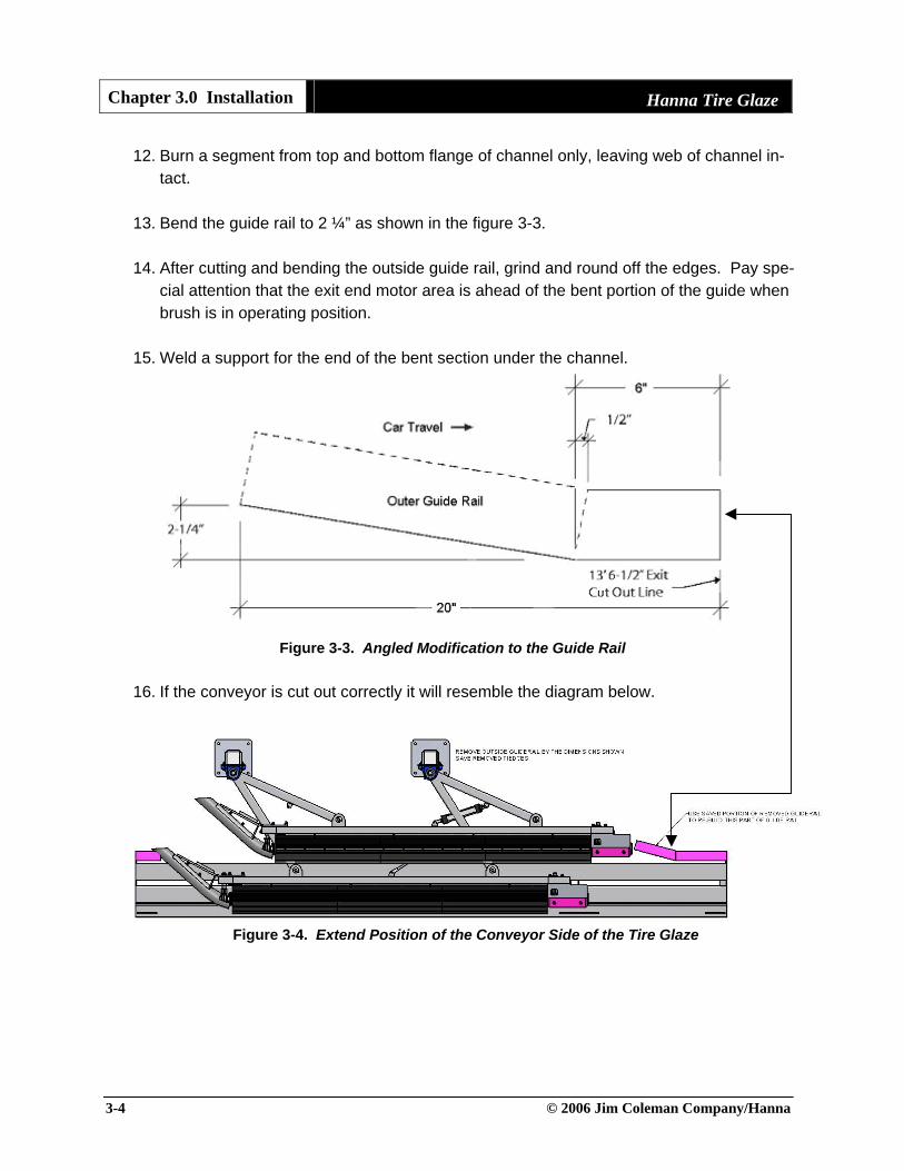
12. Burn a segment from top and bottom flange of channel only, leaving web of channel in-tact.
13. Bend the guide rail to 2 ¼” as shown in the figure 3-3.
14. After cutting and bending the outside guide rail, grind and round off the edges. Pay spe-
cial attention that the exit end motor area is ahead of the bent portion of the guide when brush is in operating position.
15. Weld a support for the end of the bent section under the channel.
Figure 3-3. Angled Modification to the Guide Rail
16. If the conveyor is cut out correctly it will resemble the diagram below.
Figure 3-4. Extend Position of the Conveyor Side of the Tire Glaze

Hanna Tire Glaze Chapter 3.0 Installation
© 2006 Jim Coleman Company/Hanna 3-5
3.4.2 Centering and Mounting the Structure
17. Move the conveyor side brush into final position and correctly align prior to anchoring down
18. Use the brush bar rather than the Tire Glaze base plate to align the unit parallel to the
conveyor.
Figure 3-5. Brush Bar Parallel to the Conveyor
19. Mark the conveyor side base plates and us the rotary hammer to drill (8) holes suitable for 5/8” X 5” anchor bolts.
Figure 3-6. Rotary Hammer
20. Drive expansion bolts into the ground
Figure 3-7. Anchor Bolt
Brush Bar

Chapter 3.0 Installation Hanna Tire Glaze
3-6 © 2006 Jim Coleman Company/Hanna
21. Double check for accuracy before anchoring the base plates. If centered correctly, there will be 76 3/4 inches from the outer edge of each base plate to the centerline. Refer to the drawings and/or M1 equipment layout for specific dimensioning.
Figure 3-8. Base Plate Positioning

Hanna Tire Glaze Chapter 3.0 Installation
© 2006 Jim Coleman Company/Hanna 3-7
22. Set the non-conveyor side of the brush using the dimensions shown. Secure to the con-crete floor in the same manner as the conveyor side of the Tire Glaze. Check for free-dom of movement and arm clearance.
Figure 3-9. Mounted Tire Glaze With Dimensions

Chapter 3.0 Installation Hanna Tire Glaze
3-8 © 2006 Jim Coleman Company/Hanna
23. If the structure is installed correctly the arms of the Tire Glaze will extend and retract without interfering with the other equipment.
Figure 3-10. Mounted Tire Glaze With Extend and Retract Dimensions

Hanna Tire Glaze Chapter 3.0 Installation
© 2006 Jim Coleman Company/Hanna 3-9
3.4.3 Height Adjustments Adjust height from floor to brush centerline based on the conditions described below
Figure 3-11. Side View With Brush Rotation
24. Conveyor Side HHSC/RCV and 3-Wheel Pushers High and Low Profile will have a 6 ½”
Height
Figure 3-12. 6 ½” Brush Clearance From Ground 25. Conveyor Side 6 Wheel High Profile Pushers will have a 7” Height
Figure 3-13. 7” Brush Clearance From Ground
Chapter 3.0 Installation Hanna Tire Glaze
3-10 © 2006 Jim Coleman Company/Hanna
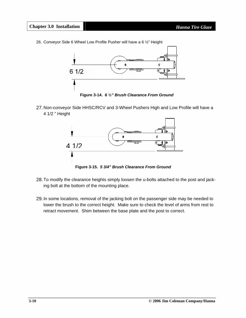
26. Conveyor Side 6 Wheel Low Profile Pusher will have a 6 ½” Height
Figure 3-14. 6 ½” Brush Clearance From Ground 27. Non-conveyor Side HHSC/RCV and 3-Wheel Pushers High and Low Profile will have a
4 1/2 ” Height
Figure 3-15. 5 3/4” Brush Clearance From Ground
28. To modify the clearance heights simply loosen the u-bolts attached to the post and jack-ing bolt at the bottom of the mounting place.
29. In some locations, removal of the jacking bolt on the passenger side may be needed to
lower the brush to the correct height. Make sure to check the level of arms from rest to retract movement. Shim between the base plate and the post to correct.
4 1/2

Hanna Tire Glaze Chapter 3.0 Installation
© 2006 Jim Coleman Company/Hanna 3-11
3.5 Pneumatic and Chemical Connections
30. The cylinder assemblies on the Hanna Tire Glaze require a total of four 3/8” poly air hose connections. Included are two tee-fitting connections (one tee fitting for extend motion and one tee fitting for the retract motion). Figure 1-4 portrays the pneumatic cyl-inder for controlling the extend and retract command to the air cylinders. Figure 1-5 por-trays the air hose diagram from the pneumatic board to the pneumatic cylinders.
Figure 3-16. Pneumatic Cylinder Assembly
Figure 3-17. Air Hose Diagram From Pneumatic Board to Cylinders
PS Cylinder
Cylinder Extend Cylinder Retract
Pneumatic Board
PS Cylinder
DS Cylinder DS Cylinder
Retract Connect
Adjust this end to control
extend speed
Extend Connect
Adjust this end to control retract speed

Chapter 3.0 Installation Hanna Tire Glaze
3-12 © 2006 Jim Coleman Company/Hanna
Figure 3-18. Pneumatic Flow Connection on the Hanna Tire Glaze Board 31. During runtime, use the pneumatic flow adjuster on the cylinder to create a smoother ex-
tend and retract movement. Turning the airflow adjustment knob inward slows move-ment. Use the stop adjustment ring to lock the adjustment screw.
32. If a high air pressure is needed to retract the brush, but this pressure is too high when
the bush is on the tire, check the arm level. Arms should be level during in and out travel. Refer to the height adjustment section of this manual to correct leveling of arms.
Figure 3-19. Pneumatic Flow Adjustment
33. Depending on tire glaze chemical used, some fine-tuning of air and chemical flow may be required so that the fluid seeps from the manifold. NOTE: The greater specific gravity of chemical used, the more air pressure required, less specific chemical gravity requires less air pressure.
Air Flow Adjustment KnobStop Adjustment Ring
¼” Poly Connection
¼” NPT Threaded Connection

Hanna Tire Glaze Chapter 3.0 Installation
© 2006 Jim Coleman Company/Hanna 3-13
3.5.1 Air Retract and Solutions Pumping Board for the Hanna Tire Glaze
Figure 3-20. Overall View
60 PSI Air Supply In
Solenoid Wiring
Arm Extend Connection
Arm Retract Connection
Chemical connec-tion to PS and DS of the Tire Glaze manifold
Feed line from chemical source

Chapter 3.0 Installation Hanna Tire Glaze
3-14 © 2006 Jim Coleman Company/Hanna
Figure 3-21. Pneumatic Solenoid Valve
Figure 3-22. Pneumatic Connections

Hanna Tire Glaze Chapter 3.0 Installation
© 2006 Jim Coleman Company/Hanna 3-15
Figure 3-23. Filter Regulator and Gauge Combo for Air In
Figure 3-24. Terminal Block

Chapter 3.0 Installation Hanna Tire Glaze
3-16 © 2006 Jim Coleman Company/Hanna
Figure 3-25. Chemical Pump
Figure 3-26. Chemical Flow Control and Solenoid

Hanna Tire Glaze Chapter 3.0 Installation
© 2006 Jim Coleman Company/Hanna 3-17
3.6 Hydraulic Connections
34. A .8 GPM flow rate at a pressure of 200PSI is required out of one priority valve from the hydraulic unit. 75 RPM is the recommended rotation speed of the motor, which is estab-lished from the priority valve on the hydraulic unit.
35. One end of one of the motors will have the hydraulic feed line, and the other end of the
other motor will have the return hydraulic line. See the figure below for a hydraulic flow diagram of the Tire Glaze motors.
Figure 3-27. Hydraulic Flow of the Tire Glaze
Note: Hydraulic pressure is supplied to the lower port of the DS motor then out the DS up-per port to the lower port on the PS Motor, out the upper PS port and back to the hydraulic tank. DS and PS can be reversed based on the location of the hydraulic unit.
36. Install all hydraulic lines and fittings. Be sure to properly install Triple-Loc fittings by tightening by had first then using the wrench make one full turn then an additional ¾ turn.
Figure 3-28. Tightening the Triple-Loc Fitting
Continues toother motor
Hydraulic return
Feed Line From Priority Valve

Chapter 3.0 Installation Hanna Tire Glaze
3-18 © 2006 Jim Coleman Company/Hanna
37. Connect hydraulic lines (both pressure and return) from the Tire Glaze to the Hydraulic Power unit.
38. Connect (electrically) the hydraulic solenoid (provided with the hydraulic unit)
Figure 3-29. Priority Valve Adjustment on the Proportionator 39. Operate the Tire Glaze. Start the hydraulic flow slowly, and gradually increase flow until
operating speed is reached. Motor speed should be 75 RPM.
40. Check for hydraulic leaks and smooth operation.
Priority Valves on a Fixed Unit Proportionator
Pressure to the Motor

Hanna Tire Glaze Chapter 3.0 Installation
© 2006 Jim Coleman Company/Hanna 3-19
3.7 Startup
41. As the vehicle approaches, the hydraulic solenoid is energized and the brushes rotate. 42. At this time the chemical pump is also energized and chemical solution is applied to the
spinning brushes.
43. The extend function is energized just as the wheel approaches the point where the brush meets the tire. This function is energized, and held until all tires have been completely covered in tire dressing fluid.
44. The brushes are then retracted and hydraulics are de-activated. This will also de-
activate the chemical pump.
3.7.1 Standard Mode
45. In the standard mode, the Tire Glaze is used in every wash package
3.7.2 On-Demand Mode
46. In the “On-Demand” mode, the Tire Glaze is used only in the upgraded wash packages chosen by the paying customer.
47. To use the Tire Glaze in the on-demand mode, the Tire Glaze is left in the retracted po-
sition. When the appropriate wash package is selected, a 24VAC signal is sent to the pneumatic and the hydraulic rotation solenoids.
48. This will then energize the pneumatic valve and cause the cylinder to extend, pushing
the brush against the vehicle. The brush will also begin to rotate.
49. The air regulator is used to adjust the force that the Tire Glaze pushes against the vehi-cle.
50. Once the vehicle has cleared the Tire Glaze, the signal is cancelled and the brush re-
turns to its retracted position.

Chapter 3.0 Installation Hanna Tire Glaze
3-20 © 2006 Jim Coleman Company/Hanna
3.8 Installation Check List Make sure that all installation procedures have been checked and confirmed to be correct.
Check Off Install Procedure
Conveyor guide rail has been cut and modified to perfectly fit the Tire Glaze
Component is mounted the correct distance from the centerline
All bearings have been located, greased, and identified for scheduled maintenance
The bumper stops have been positioned and secured
Cylinder assemblies have been properly attached and installed
Pneumatic control box is installed
Pneumatic connections lead to the correct ports
Arms and brushes properly level from the ground and set at the correct height
Brushes are perfectly parallel to the conveyor
Hydraulic connections are installed and are run with the correct volume and pressure
Electrical connections are installed with correct voltage and correct controller progamming
Brush rotation has been checked and is running in the correct direction
Start up procedures have been read and understood

Hanna Tire Glaze Chapter 3.0 Installation
© 2006 Jim Coleman Company/Hanna 3-21
3.9 Hanna Hydraulic Tubing Color Code Hanna uses colored tape on all hydraulic tubing at the factory. Figure 3-14 shows the color code on all Hanna hydraulic operated equipment.
Figure 3-30. Hydraulic Color Coding

Chapter 3.0 Installation Hanna Tire Glaze
3-22 © 2006 Jim Coleman Company/Hanna
This page is intentionally left blank

Hanna Tire Glaze Chapter 4.0 Parts and Maintenance
© 2006 Jim Coleman Company/Hanna 4-1 Rev 1.0
4.0 Parts and Maintenance 4.1 General Maintenance The Hanna Tire Glaze requires periodic inspection and maintenance. However, there are only a few items that should be inspected on a regular basis. For the first month of operation check, on a weekly basis, hardware for tightness, bearings, vertical-mount legs, anchor bolts, and motor mounts. 4.1.1 Daily Maintenance
Check the unit for proper operation prior to washing the first vehicle each day
Check hydraulic lines for leaks
4.1.2 Weekly Maintenance
Check solenoid valve for positive on/off operation Check alignment of brushes
Check bearings for proper vertical alignment
4.1.3 Monthly Maintenance
Check hydraulic lines and water hoses for wear or rub
Check frame, legs, and cross beams for cleanliness
Check frame, legs, and supports for cracks and loose bolts
Check all bearings for wear

Chapter 4.0 Parts and Maintenance Hanna Tire Glaze
4-2 © 2006 Jim Coleman Company/Hanna
4.2 Lubrication Any lubrication program is only as good as the lubricants used. So we suggest you review this in-formation and stock up on the best lubricants available. It is recommended that once you decide on a type of lithium grease that you stick to the same type of lithium grease when you lubricate your bearings Weekly: Lubricate bearings using high-quality multi-purpose lithium grease. Lubricate brush spin-dle bearings using high-quality multi-purpose lithium grease. There are two types of bearing used for the Hanna Tire Glaze: (8) Pillow block bearings used for arm movement, and (4) rod-end bearings used for brush rotation. Over time these bearings will require replacement and some disassembly of the Tire Glaze will be required.
Figure 4-1. Arm Bearing (left) and Hangar Brush Spindle Bearing (right)

Hanna Tire Glaze Chapter 4.0 Parts and Maintenance
© 2006 Jim Coleman Company/Hanna 4-3
4.3 Spare and Replacement Parts List
813953 - Brush Assembly 010439 – Pillow Block Bearing 058040 – Hangar Bearing
366065 - Hydraulic Motor 802032 – Brush Bar Pin 361263 – Cotter Pin
804764 – Bearing Pin 802127 – PS PVC Bumper 3802128 – DS PVC Bumper

Chapter 4.0 Parts and Maintenance Hanna Tire Glaze
4-4 © 2006 Jim Coleman Company/Hanna
802042 – Bushing 366898 – Pneumatic Cylinder 367094 – Rod-End Bearing
368068 – Flow Control Fitting 231753 – Split Coupling Assembly 091363 – Rubber Stop
247270 – Drive Spindle 363057 – U-Bolt 814167 – Pipe Spacer
813965 – Brush Panel Insert 814168 – Vinyl Cover 814165 – Vinyl Clamp

Jim Coleman Company/Hanna Car Wash Systems
Main Office
5842 West 34th Street Houston, TX 77092
800-999-9878 • 713-683-9878 • Fax: 713-683-9624 www.jcolemanco.com
Hanna Division Office 7905 Blankenship Dr. Houston, TX 77055
866-683-6615 • 713-683-6615 • Fax: 713-590-6630 www.hannacarwash.com

Jim Coleman Company/Hanna Car Wash Systems
Main Office
5842 West 34th Street Houston, TX 77092
800-999-9878 • 713-683-9878 • Fax: 713-683-9624 www.jcolemanco.com
Hanna Division Office 7905 Blankenship Dr. Houston, TX 77055
866-683-6615 • 713-683-6615 • Fax: 713-590-6630 www.hannacarwash.com