tips for successful internal heat exchanger ... - …hecat-inc.com/flushing technical paper...
TRANSCRIPT

1
Flushing Technical Paper
A White Paper by HECAT® ___________________________________________________________
TIPS FOR SUCCESSFUL INTERNAL HEAT
EXCHANGER FLUSHING & CLEANING
AIR CONDITIONING SYSTEMS Evaporators, Condensers, & Line Sets
OIL COOLING SYSTEMS
Transmission, Engine, & other Oil Coolers
ENGINE COOLING SYSTEMS
Heater Cores, Radiators, Blocks, & Heads
_______________________________________________________________________________________________________________________
THIRD EDITION – JULY 2015 Copyright (C) HECAT, Inc. (2015). All Rights Reserved.
Copyright Release: This document and translations of it may be shared, copied, published, distributed, and/or furnished to others; provided that this document itself is not edited or
modified in any way, such as by changing, adding, or removing text, removing this copyright notice, and or references to HECAT, Inc.
2
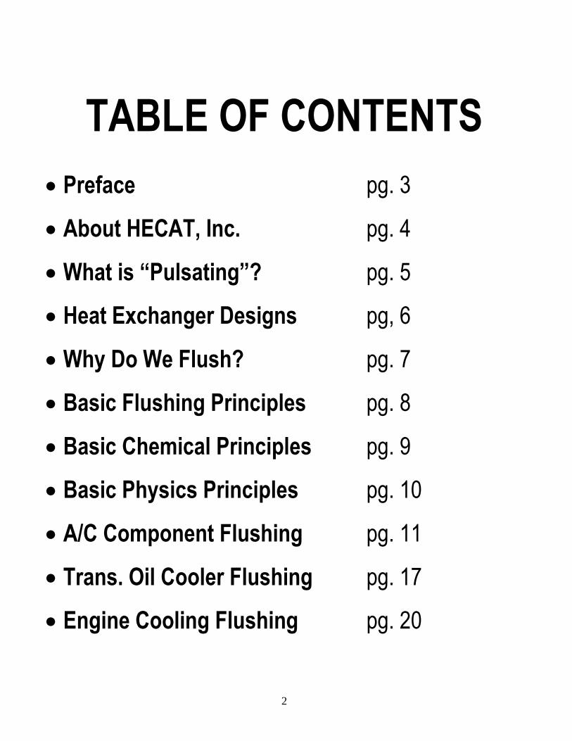
TABLE OF CONTENTS
Preface pg. 3
About HECAT, Inc. pg. 4
What is “Pulsating”? pg. 5
Heat Exchanger Designs pg, 6
Why Do We Flush? pg. 7
Basic Flushing Principles pg. 8
Basic Chemical Principles pg. 9
Basic Physics Principles pg. 10
A/C Component Flushing pg. 11
Trans. Oil Cooler Flushing pg. 17
Engine Cooling Flushing pg. 20

3
Preface Who should read this? Technicians, Educators, Students, Managers, Owners, Engineers, and Industry Sales Professionals seeking effective solutions and understanding about proper and effective cleaning of heat exchangers. For those who have had failures or negative results with ineffective methods and believe that certain components cannot be flushed. For some “seasoned” professionals this may all just seem to be common sense, and for some “rookie” professionals it may all seem to be new. Regardless of your level of experience, we hope all can gain something beneficial from this read. Our goal with this writing is to offer our understanding why many of the flushing products and processes offered today do not work, and what does work. To share information we have gathered regarding component designs, systems designs, problems, issues, and how to overcome and or resolve such issues. To take a common sense approach to explain the physics & chemistry principles to understand what works, what does not, and why. First, let’s be sure to clarify; “flushing” is a term that has been applied to Fluid Exchange Equipment. Fluid Exchange Machines produce varying results in evacuating old fluid, to replace it with new, and some will provide some minimal cleaning. But when facing a contaminated heat exchanger or system restricted from buildups or full of particulates from a failure, this equipment just cannot get the job done. The ultimate goal for all parties involved with system repair, is to be sure the job is done right the first time, in the most economical and professional manner; and that the repaired system will operate properly for many miles. Regardless of the heat exchanger application and what equipment, method, and chemical you choose to use; it is ultimately the technician’s responsibility that the flushing project has a positive, rather than a negative effect on the system. Flushing done right is a proven way to reduce the expense of comebacks and warranty repairs. Flushing done wrong just adds to the problem. Keeping your customers repair costs to a minimum and providing repairs that give long trouble free service will only strengthen your reputation, profitability, and referrals. Compact Heat Exchangers that are most commonly used in transportation have been constantly changing over the years. Simple single paths have changed to complex multiple paths; as the need for more surface area and heat exchange efficiency is required, while also meeting the ever decreasing overall weight and size requirements. What used to be a fairly simple single path flushing process has become more and more complex with the introduction of designs that use multiple small passageways (micro channels) connected to common chambers. These designs present challenges to clean, as the cleaning process must now be able to overcome the “path of least resistance”; that is to say that a steady and constant liquid flow will take the path of least resistance, and when provided with the opportunity, it will pass around an obstruction. No longer will a simple “pour in” and “blow out” processes work, and neither do the products that have grown from this concept, such as the products packaged in aerosol spray cans or the 1 qt flush gun (a “you fill” aerosol can). Even professional equipment that just circulates a cleaner will not penetrate all the circuits within modern heat exchangers as needed; and will just flow over, under, or around debris, even when flushing for hours. At HECAT®, we believe that aggressive marketing of ineffective tooling and chemicals, combined with a failure, at times, for the technician to completely understand the difficulty and many variables involved; can and will derail the task. This ultimately creates too many unsatisfactory results and frustrations. “Throwing in the towel” is not a solution. Taking the time to analyze and understand why the process chosen did not work, and implementing alternatives that do work; is the solution. Proper and effective flushing will eliminate comebacks, warranty issues; and extensive, expensive, and unnecessary component replacement. It can be done properly and in a timely manner, and is proven as an effective and economical alternative.

4
About HECAT, Inc. Heat Exchanger Cleaning & Applied Technologies
Since 1982, HECAT® has focused on research, development, patents, engineering, and the manufacturing of effective equipment, processes, and proven procedures for cleaning the complex internals of compact heat exchangers used in many forms of transportation; such as, Air Conditioning Evaporators and Condensers, Transmission and Engine oil coolers, Hydraulic Circuits & Lines, Radiators, Heater Cores, and the Cooling System. Our successful history has come from years of supplying commercially available, private branded, and specialty application tools, chemicals, and procedures that efficiently and effectively get the job done right the first time; and by offering unrivalled warranty coverage and technical support. Manufacturing and system breakdowns will produce particulates and residues; which if not properly removed, can and will contaminate a repaired system, producing inadequate thermal transfer, and most likely cause a repeat failure. Effective cleaning eliminates the costs and extensive labor efforts to access and replace heat exchanger components. HECAT® is recognized by many Automotive, Fleet, and Aviation OEM’s, to be a valued supplier and consultant; by producing OE essential and required tools and providing solutions to meet the various cleaning requirements of many heat exchanger applications. Many times we are supplied problem components, complete systems, and some of the worst real world failures imaginable; to test and understand the customer’s specific heat exchanger cleaning issues, and what to apply as a solution. We dissect components and study the designs. We apply known weights of various size debris and oils to different component designs and then flush with various methods and chemicals. We know what can be done and what cannot, and we know what is realistic to be accomplished in the field and what is not.
Markets Served: Focused On Cleaning:
Automotive Repair A/C Condensers
Business & Commercial Aviation A/C Evaporators
Fleet-Truck-Bus Transmission Oil Coolers
Heavy Equipment Engine Oil Coolers
Motorcycle Radiators & Heater Cores
Marine Hydraulic Systems & Lines
Refrigeration Manufacturing Heat Exchangers in Manufacturing
Aircraft Manufacturing Avionics Cooling Systems
Industrial Galley Refrigeration Systems
Power Plants Cryogenic Systems
Military Pools, Plumbing Lines, & Drains
Agriculture Aircraft Cabin & Crew A/C Systems
Mining Charge Air Coolers
5
What is “Pulsating”?
“Pulsating” is the HECAT® PULSATOR® US trademarked and patented (Pat. 5615695 & 9233404) process, which uses no pump or moving parts. It uses fixed dimensional control of compressed air and liquid flow paths; to produce solid impacting slugs of liquid. It is just like applying the “elbow grease” energy of a parts washer scrub brush down inside a component. PULSATOR® tools will hammer slugs of liquid deep into the internals of a heat exchanger, allowing them to scrub deep into corners and crevices; to not only knock loose trapped debris, but to also maintain it in suspension so it can be removed. The “Pulse” is intensified with back pressure, so it scrubs harder at restrictive points. The compressed air is regulated to a safe level that is appropriate for the components being cleaned. Then the regulated pressure is even further reduced by converting the stored energy within the compressed air into kinetic velocity by means of the “Bernoulli Effect”; this ensures we never damage a component with excessive pressure. The “Pulsating” frequency averages about 5-6 “pulses” per second, and when combined with the high liquid flow rate, will defeat the “path of least resistance” rule and effectively scrub down deep into the parallel paths and passageways to effectively and quickly clean and clear debris from today’s complex heat exchangers. HECAT® PULSATOR® Flushers are simple, effective, economical, rugged, durable, and easy to use. The quality and durability of this process has produced many years of satisfied customers. History has shown that almost all PULSATOR®
equipment service issues are related to not servicing (not changing fluid) or from the use of incompatible fluids. To reduce the occurrence of such issues, HECAT® now offers a Lifetime Warranty on many models; by simply requiring regular fluid servicing and the exclusive use of the HECAT SAFE-FLUSH® solvents.
BUYERS BEWARE: Make sure it is an original HECAT PULSATOR Flusher. We have been at this for a long time, and it is a compliment to the HECAT proven process; that others try to capitalize on this success, by marketing and claiming to pulse. Without access to the HECAT patented process, many are using air operated diaphragm pumps, bleed valves (air bubbles), and cycling control valves, pumps, or motors on and off repeatedly to produce their pulse. However, this also produces high cyclic component wear, failure, down time, and maintenance costs. Unlike the true kinetic energy of the HECAT process, which is pulsing just as strong on component exit; these visually appealing pulse methods just rapidly dissipate into the solid liquid stream and add NO true energy to the cleaning process. Why pay for something that sounds good and looks good, with cyclical wear and failure potential, which adds no true energy to enhance the cleaning process?

6
Heat Exchanger Designs
◄ Tube & Fin components use a long common tube or tubes in a continuous path back and forth thru the fins ►
◄Serpentine components use a bundle of smaller tubes that also weave back and forth thru the fins ►
◄Parallel Flow components use multiple bundles of small tubes that pass through the fins to common chambers, through the next bundle of small tubes to the next chamber (aka Micro Channels) ►
◄Cross Flow uses multiple tubes to pass from one main inlet header chamber to the main outlet chamber. This is a common of radiators and heater cores.
◄This is another example of Cross Flow, Single Pass, or sometimes called Open Chamber. This is also the design of many evaporators and oil coolers
Another example of Parallel Flow or Multi-Pass ►
◄Open Web describes the mesh inside an individual
segment of a common OEM style in radiator transmission oil cooler. These segments are stacked together and sometimes called Stack Plate and
fluid flows in a path similar to Cross Flow or Open Chamber.
7
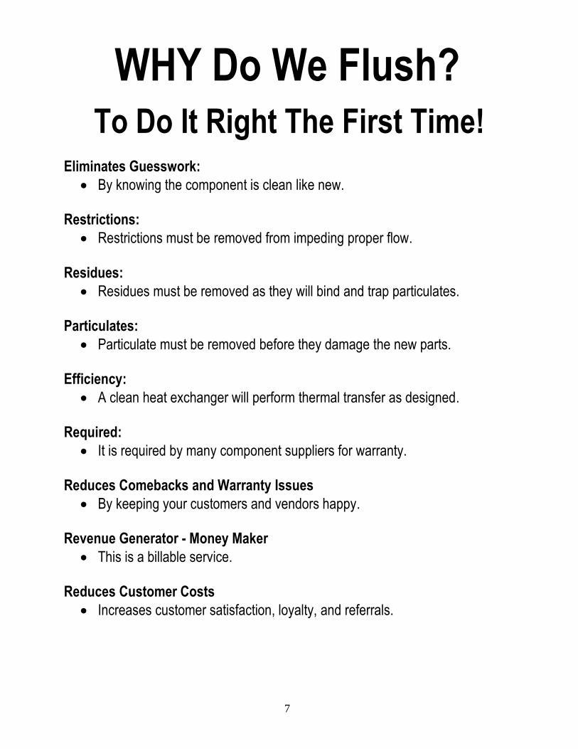
WHY Do We Flush?
To Do It Right The First Time!
Eliminates Guesswork:
By knowing the component is clean like new. Restrictions:
Restrictions must be removed from impeding proper flow. Residues:
Residues must be removed as they will bind and trap particulates. Particulates:
Particulate must be removed before they damage the new parts. Efficiency:
A clean heat exchanger will perform thermal transfer as designed. Required:
It is required by many component suppliers for warranty. Reduces Comebacks and Warranty Issues
By keeping your customers and vendors happy. Revenue Generator - Money Maker
This is a billable service. Reduces Customer Costs
Increases customer satisfaction, loyalty, and referrals.

8
Basic Flushing Principles Think for a moment about the varying number of vehicle (car, truck, bus, aircraft, etc.) models, system designs, heat exchanger designs, types of failures, debris loads, debris sizes, oil residues, additives, etc.; the failure variables become almost limitless. Understanding the key basics will allow you to procedurally eliminate and mitigate these many variables; to become confident and successful with your flushing efforts.
Identify the System You must be aware of individual inherent issues of the system and heat exchanger designs being used. For reference, some A/C system diagrams and explanation of “Heat Exchanger Designs” have been included in this document.
Analyze the Failure The technician must evaluate and understand the specifics of each individual failure like a crime scene investigator. You can pick up enough trace evidence here and there, which can paint a mental picture of what has happened; and what conditions exist internally that you wish to remedy. You must understand the severity of the failure and the debris load that may be present; as well as other dirt, contamination, and residues to be removed; to meet the goal of a clean component.
Identify the Flow Paths Knowing and understanding the flow direction and pathways within the components and the complete system is critical for successful flushing. You have got to understand how contamination enters to effectively remove it.
Remove Restrictions Complete or partially assembled systems cannot be flushed. You must always isolate the heat exchangers and flush through the most direct and unrestricted path to obtain the most satisfactory flushing results. You cannot flush through check valves, compressors, filters, orifices, or any device that would slow or restrict the heat exchanger flushing process.
Know How Debris Enters Understanding how debris gets into a heat exchanger is critical to know how to get this debris out.
Traps & Concerns Knowing the component designs, intricate pathways, system designs, and points of concern where solvents will pool or debris and residues will accumulate is critical for successful flushing.
Direction to Flush Larger debris cannot be pushed through the small passageways and must be back flushed out of the component.
Chemical Cleaners See “Basic Chemical Principles” and specific details in A/C, Transmission Oil Cooler, & Cooling System Flushing.
Delivery Method See “Basic Physics Principles” and specific details in A/C, Transmission Oil Cooler, & Cooling System Flushing.
Removing the Cleaner Cleaning solvents cannot be left behind in the heat exchanger. Suitable methods to recover and remove the remaining solvents must be employed. Before ever putting a chemical in, be sure you know how you are going to get it out.
Test to Verify We should never assume the process has worked, and we must do our diligence and employ something to provide adequate confirmation (proof).
Filters Filters provide insurance after flushing, but they will never work as an alternative to flushing.

9
Basic Chemical Principles The chemical properties of a solvent or cleaner will displace, dissolve, or in some way chemically alter the contamination on a surface. The physical properties of a solvent such as surface tension effects the fluids ability to penetrate small spaces, cracks, holes, and get between the contaminant and the surface to displace the contaminant. There are many chemical products available today with vague content descriptions and unfounded claims regarding the
performance of their products. This is why we say, you must be “Smarter than the Label”. Whatever chemical you choose to use, it is your professional responsibility to:
Obtain a MSDS with sub component CAS numbers. It is extremely important you know what you are using.
Understand the effectiveness of both the chemical and physical properties of the product you chose to use.
Know how and why this chemical will remove the undesirables (or the vehicles paint).
Know how this chemical will be removed from the system when cleaning is completed.
Know it is compatible with the metal and elastomer materials of the system, components, and the flushing equipment.
Know the toxicity, hazardous classification, flammability, combustibility, and proper handling.
Know the local, state, and federal regulations regarding the use and disposal of the products you choose. HECAT’s goal is to produce, use, or recommend solvents and cleaners that meet the chemical and physical requirements of the particular cleaning task. We practice “Cleaner Technology” principles and always consider the technicians exposure, environmental releases, fume containment, and methods to recycle; in the development of our products, equipment, and recommended procedures. There are three primary types of solvents and cleaners that we use for various heat exchanger and other cleaning processes.
(1) Hydrocarbons are comprised of petroleum distillates, synthetic (paraffinic) hydrocarbons and Terpenes (distillates from plant oils). Hydrocarbons have a high solvency for “hard-to-clean” organic soils, including heavy oil, grease, and tar. They have a low liquid surface tension, which allows them to penetrate and clean small spaces. Many hydrocarbons are blends and less volatile components may be left on the parts after the bulk liquid has evaporated. Where residues are an issue, only a 100% volatile (evaporative) product should be used; and slow drying is accelerated with forced air.
See the HECAT SAFE-FLUSH® products.
(2) Hydrofluorocarbons, as with the chlorinated and now regulated CFC-113, CFC-11 and HCFC-141b solvents of the past, Today’s HFC’s are used for precision cleaning, foam blowing, and refrigeration. HFC’s target applications where non-VOC, low toxicity, low residue, and non flammable solvents are required. HFC’s high solvency and low boiling points make them an excellent choice for A/C flushing, where rapid evaporation by vacuum recovery leaves no solvent residue.
See the HECAT H1000 flusher which uses Honeywell’s Genesolv® SF. (3) Water is used with our Engine Cooling Pulsator. The effectiveness of the pulse energy to scrub the surfaces, penetrate all the paths, suspend the particulates, and carry it all out with the outflow; requires no solvent to do so. With water as the cleaner, this outflow can often go to ground, or to the sanitary sewer system; eliminating solvent costs and disposal.

10
Basic Physics Principles It is globally accepted that industry standard methods to clean heat exchangers in aircraft, refineries, oil rigs, heavy equipment, trucks, and automobiles will require some form of appropriate cleaning chemical, velocity, and agitation.
Laminar & Linear Flow
Systems for the most part are designed for smooth flow without cavitations or vibration, and therefore will require some turbulence in order to provide effective cleaning. Smooth flow allows for swirls, eddies, and pools to occur in the corners and crevices of the heat exchangers where residues will accumulate and trap or bind debris. This is why simple circulating equipment will not get heat exchangers completely clean. Even the best suited chemicals for the job will produce poor results; if not introduced with the adequate enhanced energy necessary to scrub the internals and to dislodge trapped debris and carry it away. It is just like holding a dirty part under your parts washer outflow; you know the cleaning will be accelerated and improved when you add your scrub brush.
Mechanical Energy
Some form of mechanical energy is almost always used to enhance a solvent cleaning process. The brush in your parts washer, agitation, pulse, vibration, and ultrasonic; are some examples of typical methods that are used to apply energy to enhance a cleaning process. The multiple passageways common to heat exchangers used today, will allow for a simple flowing cleaner to take paths around a restriction. Mechanical energy must be used to overcome the “path of least resistance” rule. HECAT uses its high frequency Patented PULSATOR technology and other methods to effectively apply the needed mechanical energy to properly penetrate and clean the internals of a heat exchanger.
Velocity
Velocity is another energy component that is critical to successful heat exchanger cleaning. The solvent must be introduced with adequate velocity to completely flood the component. Velocity is a necessary energy component needed to carry away weighted debris. Velocity cannot be sustained if the solvent is not introduced with an adequate volume to support it. This is why aerosol cans and 1qt. flush guns will not work.
Volume
Solvent volume is critical. There must be enough solvent supplied to support the velocity of the flushing process and there must also be enough solvent supplied to effectively do its job at dissolving the residues. This again, is why aerosol cans and 1qt. flush guns will not work.

11
A/C Component Flushing
Overview Today there are so many issues, myths, phobias, and concerns regarding A/C component flushing; these issues have caused many in the A/C service industry to shy away from this proven, effective, and common service practice. In the following A/C section, we will cover both successful solvent and refrigerant flushing methods. As an A/C system ages, the oils will breakdown and begin to loose some of their lubricity. As the compressor wears it puts fine wear particles into the system that on their own are small enough to pass through most screens, orifices, and expansion valves. When these fines combine with the degrading oil, this is where the problems begin. The orifices and screens will begin to clog; the lack of clean oil and the effects the contaminated “Goo” will have on the compressor begins the “Domino” effect towards catastrophic compressor failure. A low refrigerant charge is the number one cause that will accelerate such a lack of lubrication failure. In cases like this, how can you hang a new compressor, add a few ounces of oil, vacuum, recharge, and not expect this repair to come back? There is only one way to know exactly how much oil to put back in a system, and that is to start with a clean and dry system. This can only be accomplished by total system replacement or by the use of an effective and proven flushing method.
OEM: Some OEM’s do approve certain flushing methods, but in general, many don’t approve flushing at all. Many OEM’s used to approve flushing back in the day of R-11 and with other products now regulated, but most OEM’s have slowly moved away from flushing as they have seen way too many problems associated with remaining solvents and oil dilution. These issues will cause repeat failures and are directly related to the use of improper techniques, inadequate solvents, and poor performing flushing methods. This is further perpetuated by the fact that newer systems today are tighter and are lasting longer, which means that most OEM’s do not need to support component flushing as a published service procedure. We have produced essential tools and OEM’s are almost always engaged in some form of testing with us. Flushing through a Thermal Expansion Valve and other solutions will produce huge savings over the labor and material costs of a total system replacement. Hybrid compressors, modular components, new refrigerants, and other future system changes; are going to continue to increase the cost of total system replacement. How do the majority of the OEM’s get away without flushing? OEM service procedures and responsibility are focused on the first 3-5 years of the vehicles warranty life. Because most of the systems they service are virgin, they can perform component replacement and “oil balancing” with a reasonably high level of success. If this becomes a repeat failure, they just replace the entire system. If OEM’s choose total system replacement over flushing, is this the only way? In no way are we saying that you should not follow OEM procedures, but is it not true that many aftermarket services, that benefit both the technician and customer are performed successfully every day without OEM approval?
Aftermarket: To maintain their warranty, it is required by most aftermarket component and compressor manufacturers, that you properly flush the system when you make repairs and/or replace components. In the aftermarket, we see the cars after the “cousin” or “uncle” has topped it off a few times. What kind of refrigerant blends have been used? How many oil charges did he shoot in there? Has a seal swelling product or the dreaded hardening sealer been put in there? What kind of a crazy concoction has all this stuff become? All of a sudden the OEM “Oil Balancing”
12
procedure of installing a new component and a few ounces of oil is not going to work with the same high degree of success as it does on virgin systems. Many Compressor manufacturers are telling us that many compressors being returned for warranty evaluation have solvents in the oils, some even “smell” like solvents. Compressor manufacturers also confirm our position; that flushing is necessary and flushing is not the problem, but doing it correctly is (selecting the right chemical, flushing method, and properly removing the solvent). This is exactly the same issue OEM’s have seen, that has caused them to shy away from recommending solvent flushing.
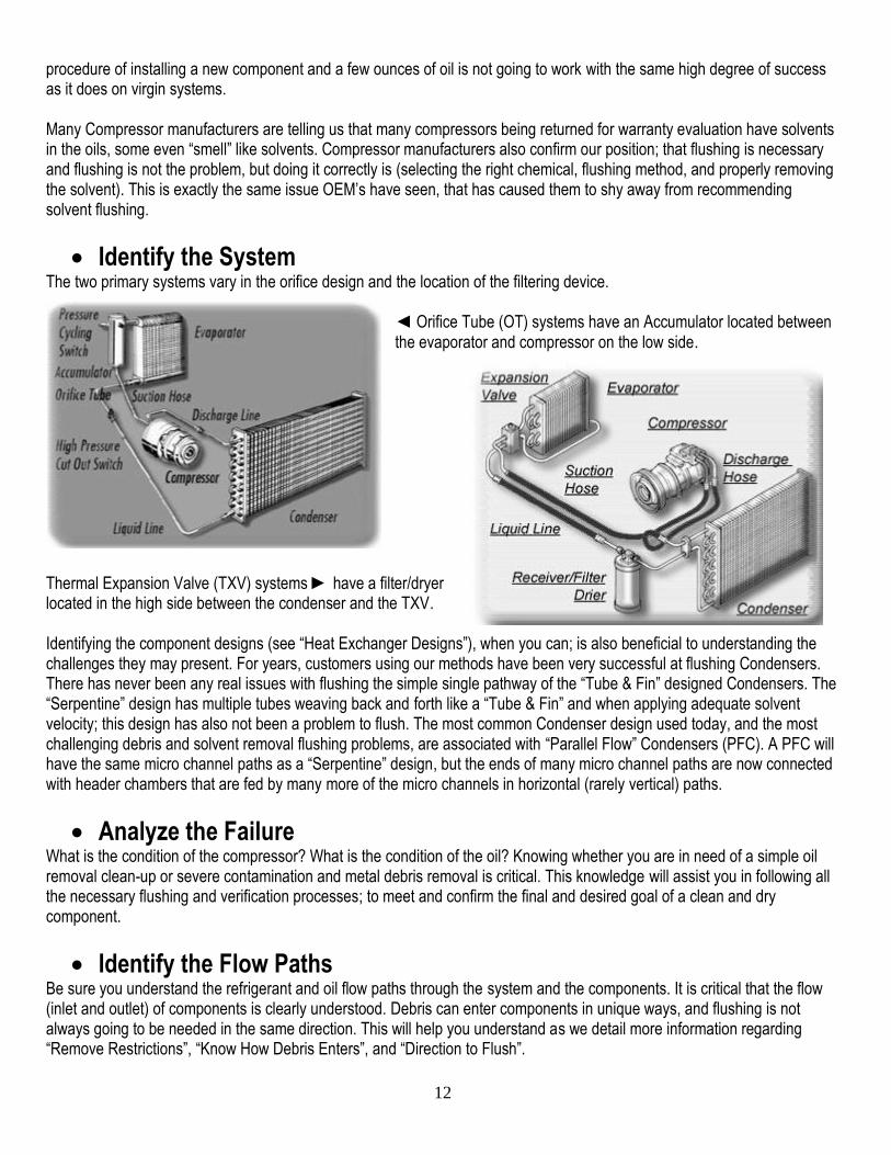
Identify the System The two primary systems vary in the orifice design and the location of the filtering device.
◄ Orifice Tube (OT) systems have an Accumulator located between the evaporator and compressor on the low side.
Thermal Expansion Valve (TXV) systems ► have a filter/dryer located in the high side between the condenser and the TXV. Identifying the component designs (see “Heat Exchanger Designs”), when you can; is also beneficial to understanding the challenges they may present. For years, customers using our methods have been very successful at flushing Condensers. There has never been any real issues with flushing the simple single pathway of the “Tube & Fin” designed Condensers. The “Serpentine” design has multiple tubes weaving back and forth like a “Tube & Fin” and when applying adequate solvent velocity; this design has also not been a problem to flush. The most common Condenser design used today, and the most challenging debris and solvent removal flushing problems, are associated with “Parallel Flow” Condensers (PFC). A PFC will have the same micro channel paths as a “Serpentine” design, but the ends of many micro channel paths are now connected with header chambers that are fed by many more of the micro channels in horizontal (rarely vertical) paths.
Analyze the Failure What is the condition of the compressor? What is the condition of the oil? Knowing whether you are in need of a simple oil removal clean-up or severe contamination and metal debris removal is critical. This knowledge will assist you in following all the necessary flushing and verification processes; to meet and confirm the final and desired goal of a clean and dry component.
Identify the Flow Paths Be sure you understand the refrigerant and oil flow paths through the system and the components. It is critical that the flow (inlet and outlet) of components is clearly understood. Debris can enter components in unique ways, and flushing is not always going to be needed in the same direction. This will help you understand as we detail more information regarding “Remove Restrictions”, “Know How Debris Enters”, and “Direction to Flush”.
13
Remove Restrictions You cannot flush through charging ports, compressors, filters, or orifices. Flushing is only effective when we can apply a volume of solvent with velocity (see “Basic Physics Principles”). This is done by removing restrictions, separating, and isolating the heat exchangers for high flow flushing (Yes, we can use the hoses). Just as important as flushing cleaner inflow; is the outflow, where larger debris will need the necessary clearances to be able to come out. Note: Refrigerant Flushing CAN flush thru a TXV and Solvent Flushing cannot (explained in “Delivery Method”).
Know How Debris Enters The Evaporator of an OT system will see lots of contaminated oil and limited debris that will enter through the existing, missing, or damaged OT screen. The Evaporator of a TXV system will see lots of contaminated oil and debris is limited from entering the evaporator through the high side filter. However, in the case of a catastrophic internal compressor failure, with nothing (some suction hoses will have mufflers) between the evaporator and the compressor on the low side; rapid pressure equalization can blow large compressor debris back into the evaporator. This is not a theory; we have seen the evidence to confirm it as fact. Condensers receive debris from a compressor failure directly to the inlet and it is usually slammed in with some velocity given the high side pressures.
Traps & Concerns Flush can pool and become difficult to remove from the "well" found in the bottom of many “open chamber” evaporators as well as the header chambers of “parallel flow” evaporators and condensers. This is also an issue of concern with mufflers and it is recommended that if you do flush hoses with mufflers, be aware that there may be extra effort required in the solvent removal and verification steps. It has become a common practice today to just replace the condenser. We do support the fact that this is the technician’s decision and we do say “when in doubt, pull it out”. In severe debris cases, flushing with a high energy process such as what HECAT offers may be the only way to get the larger debris pieces to churn around in the inlet chamber and bring it out; it can be done. Obviously, if a compressor failure is not a consideration; a PFC can easily be flushed of the waste oils, and reused. OEM Heat Exchanger Component Manufacturers are beginning to use modular cooling systems up front that incorporate the radiator, transmission oil cooler, A/C condenser, electronic cooling, and more as ONE very expensive single component. As this will become more of a common production component, the inexpensive and “easy change” characteristics of today’s condenser will go away and proven condenser flushing methods will have to be employed. The hard carbonized oils from a severe burnout can be removed by refrigerant or commercial flushing chemicals; this buildup is “burnt” oil and may be called “black death”, but it is not the hardening Teflon issue from the true “black death”. That was a specific model and compressor issue that has now long passed. However, we have seen black and grey residues in late model systems, that seem to have adhered itself to the walls of the component similar to aluminum anodizing. We had this analyzed with Molecular Spectroscopy, which identified it to be carbonized or polymerized PAG oil. The OEM who supplied these components agreed to put them back in service after flushing; and after years of field testing, they confirm that this coating has negligible effects on heat transfer or system performance. It is recommended that you use only flush and equipment that is approved for the removal of sealers. If you suspect sealers were in the system you just opened, it is critical to flush immediately before any remaining sealer tries to harden in the systems components. Yes, uncured silicate sealer can be removed but it will require an immediate flush, when the system is opened, before the product cures.

14
Direction to Flush Following the principles outlined in “Know How debris Enters”; lets get it out in the correct direction. Condenser flushing is the same regardless of the differences in OT and TXV system design. You should always back flush first (bottom to top), in the opposite direction of normal refrigerant flow. This is done to back out debris that cannot be driven through the small passageways and obviously will require some solvent volume and velocity when flushing “in car”. If the desiccant housing is integral to the condenser, the desiccant & screen must be removed and the housing resealed; before flushing the condenser. Some of these integrated desiccant housings are not serviceable, and unless you want to consider removing the integrated housing and splicing in an aftermarket filter; such a condenser should be replaced. When Solvent Flushing the Evaporator; the TXV or OT should be removed and the component should be flushed through the smaller line in the same direction as the refrigerant flow. For vehicles with a rear air evaporator, the recommended procedure is the same; access the rear evaporator, remove the TXV, and flush. While disconnected from the front and rear, the long hoses can be connected together at one end and also flushed as another component. Note: Refrigerant Flushing CAN flush thru a TXV and eliminate some of these steps (explained in “Delivery Method”).
Chemical Cleaners The commercial solvent chosen must be 100% volatile for it to completely evaporate and be removed. Oil based flushes usually have a solvent component that will evaporate and leave the oil base behind. This is why we previously covered the importance of, and emphasize again, the importance of studying and understanding the “Basic Chemical Principles” before
you choose to use a product. Remember, you must be “Smarter than the Label”.
Delivery Method Following and meeting the outline of the “Basic Flushing Principles”, here we will explain two proven and effective methods. Solvent Flushing: HECAT’s long history with the air operated “Pulsating” Flushers (see “What is Pulsating”) has proven the effectiveness of this hard hitting and scrubbing process. Solvent flushing can be done very quickly and efficiently with many models available from a DIY High Volume Pulsator® Flush Gun , and two models of our “Professional Pulsator Series”; FAC-200 Pulsator® & FAC-400 Pulsator®. The Professional flushers include adapters to connect to over 90% of today’s components, features for solvent purging (removal), and have a Lifetime Warranty available. A non-restrictive T-Strainer is installed in the return line of all models of our professional A/C component flushers. This allows for visual monitoring of the flushing process and progress, as well as being used in final testing and confirmation. Refrigerant flushing is something that was widely accepted in the past with now regulated products such as R-11, R-113, and R-141b. Refrigerant flushing is being called for by the OEM’s as an obvious solution to residual solvents, flammability issues, and system compatibility. The use of a HFC compatible refrigerant flush, with the right boiling point (Not R-134a) to perform as a flush; is PAG and POE miscible (blends), non-flammable, recoverable, leaves no residue, and can be recycled, thus making it very cost effective. R-134a has a minus 15 degree F boiling point, which allows for this product to gas so readily in these heat exchangers; and as a gas it becomes useless as a flush. R-134a manufacturers know and understand this chemical nature, and we don’t see them supporting or marketing their R-134a as a flush, do we? No, they are offering different HFC products for flushing. The success of the past refrigerant flushing products was primarily due to a higher boiling point than R-12 or R-134a. This allowed for them to stay as a liquid under light pressure to flush; but also had a low enough boiling point to be completely
15
recovered under vacuum. This is why we chose to develop a “Refrigerant” flusher (see H1000) using Honeywell’s Genesolv® SF (HFC-245fa), which has a 60 degree F boiling point. With TXV’s on the passenger side of the fire wall, rear air situations, and aircraft interiors; flushing through a TXV is desirable because of the difficulty to access these components. There was success at this in the past with regulated refrigerant flushes such as R-11 and R-113. This cannot be done with the commercial flushing solvents available today and “Refrigerant” flushing is the only way possible. Our testing with OEM’s, who have supplied us with numerous complete systems that suffered catastrophic compressor failure, has produced excellent results. After following the specific instruction in the H1000 operating manual on how to test, verify, and if necessary clear the TXV and or the screen; component flushing can be done through the lines and TXV without extensive interior removal. Although the initial cost of the H1000 and Genesolv® SF may be met with some concerns; the return on investment (ROI) analysis shows it to be extremely cost effective, because the H1000 distils and recycles the Genesolv back to virgin form for reuse over and over again. Even when factoring in accidental releases, such as connectors not installed properly, and the energy usage; it costs no more than $1.00 per component flushed. In an ROI comparison against the use of a common flush gun and one time use of solvents costing $50-$60 per gallon; the H1000 will pay for itself in about 75 vehicles. That’s right, in just 75 vehicles the H1000 is still recycling and has paid for itself. On the other hand, you have paid $75.00 for a flush gun and 8 to 9 thousand dollars of used solvents, to dispose of. Some Recovery and Recycle manufacturers have added flush features to their equipment; but the process of flushing through the charging ports is not feasible. Flushing through the charging ports just pushes debris from component to component and does not provide for a clear (or large enough) path that debris can exit. Even when using processes that require the isolation of the heat exchanger, it still has flaws. Refrigerant Recovery equipment will not meet the need for volume and velocity and although they claim to be effective on removing some oils, they cannot remove all the debris. Is trying to flush out contamination something you really want to do with such an expensive, EPA required, and heavily used piece of service equipment?
Removing the Cleaner In addition to an effective cleaning method, the chemical must be properly and completely removed. The goal is a clean and DRY component; leaving residual flush in the system will dilute the refrigerant oils and cause rapid compressor failure. When Solvent Flushing with the “Pulsating” Flushers, a nitrogen purge to remove the solvent is recommended but very few facilities will have the volume of nitrogen available to perform the full volume blow. 20 to 30 minutes is required to evaporate many commercially available flushing solvents today. With our air operated “Professional Pulsating” flushers, we do include a high quality filter-separator to eliminate corrosion in the flusher; and to remove moisture and compressor oil from the air supply. We can purge solvents with compressed air, but it is extremely critical that we provide “paint booth” quality (coalescing filter & moisture indicator) dry air and blow, blow, blow! Test, and blow more if necessary. Vacuum cannot be relied upon to, and will not remove these types of flushing solvents. Regardless of the flushing direction, Air Purging for solvent removal is best done from the highest to lowest port. The H1000 Refrigerant flusher features recovery with a light vacuum and the air purge process is not necessary.
Test to Verify The weight tests, scope inspections, dissections, and other methods that we perform in our R&D department are not practical tests to be accomplished with the components in the installed position. However, there are some simple methods that can and should be employed.

16
But if the flushing process is effective, why do we need to test? It is because too many variables exist that can affect the results. This is extremely critical when facing the severe debris of a catastrophic compressor failure. Large debris can turn in the port and block the outflow, effectively canceling the cleaning action of the flushing process. If working with a known high debris load, it is recommended to look for this issue. If flushing through hoses it may even be necessary to remove the hose and inspect the port. Knowing how the debris entered, and knowing how you are going to get it out; also identifies which port you need to be inspecting for confirmation of debris removal. The basic test is known as the air “Pop” and considered by some to be “Old School”, but we prefer to consider it what “Experienced” technicians do. Using the T-strainer and Pop test valve included with the professional models we will close and release a volume of air from the component. Because of the known effectiveness for the solvents to remove all the contaminant holding waste oils and sludge, any possible remaining debris particles are now loose and dry and will readily move out with this air burst (repeated bursts). If nothing or a few very small specs are found, this confirms the component is clean. If a concerning amount of debris is burst out, or if waste oils and or solvents are present; the technician at this point may need to repeat the flushing process or further air purge, until confirmed with their complete satisfaction in a clean and dry component.
Filters We do recommend Airsept Compressor Guard suction screens, that are great for providing system protection (insurance); but they should only be installed after flushing, and not as an alternative to flushing. If you do not first flush, the filter will just rapidly clog with contamination.

17
Trans. Oil Cooler Flushing
Overview For many years technicians took it upon themselves to utilize some form of a “home made” method to flush out transmission coolers, if they did it at all. Older automatic transmissions were durable units and wear contamination flowed throughout the unit with little or no concern. Some of the very early automatic transmissions didn’t even use a pick up filter. It was not until the early eighties with the introduction of the lock up torque converter and the subsequent clutch material wear and contamination, that cooler flushing became more and more of common practice. Transmission oil cooler flushing is not something that just a few shops do; it is an absolute necessity to a professional transmission repair or replacement job. Today, because of closer tolerances, solenoid valves, computer controls, and OEM flow tests, flushing transmission oil coolers is accepted as a mandatory and a required service practice when replacing a transmission. Flushing the transmission oil cooler and cooler flow verification is a requirement for warranty on any OEM or remanufactured unit you may need to install. Most OEM Technical Service Bulletins regarding automatic transmission oil cooler flushing will have some type of a statement similar to this one from Ford: “Automatic Transmission oil cooler flushing must be performed when an automatic transmission is removed for service. The flushing procedure should be performed after the removal of the old transmission and before the installation of the overhauled or replacement transmission. Failure to flush the cooler system properly may cause damage to the transmission and it components”.
Identify the System The Transmission oil cooler is fed from the torque converter; the fluid coupler, which by its design creates most of the heat. After passing through the oil cooler, the cooled fluid returns to cool and lubricate the bearings and bushings, etc. before returning to the pan. Fluid is then picked up through the suction filter by the pump, which has a pressure relief valve bleeding off excess pressure (heat) to the torque converter. Regulated pump pressure is used to feed the hydraulic controls and actuators. All fluid paths eventually combine and enter the torque converter and out to the oil cooler to repeat the cycle.
Analyze the Failure Minor wear particles continuously pass through the cooler and directly to the lube circuit. As a transmission delivers its last days of service, this minor wear particle scenario has become much bigger, larger debris is now flowing into the torque converter, clutch material from the converter is giving up under this debris load and now this is all going to the oil cooler. Because of the fine mesh design and small passageways of most in-radiator heat exchangers; the cooler is becoming a filter for the now larger particles, which are beginning to impede or completely block sufficient oil flow and cooling, ultimately becoming a contributing factor to the final phase of the transmission failure.
Identify the Flow Paths The pressure and return lines are identified for many models in a chart included with every oil cooler flusher’s operating manual or available to download from many sites on the internet.
Remove Restrictions Filters, check valves, and thermal valves must be removed or bypassed for free flow flushing of the oil cooler circuit.
Know How Debris Enters Debris enters the cooler from the transmission via the oil cooler pressure line. Any debris that can pass through the cooler returns to the transmission via the return line. You must be able to identify the pressure and return lines.
18
Traps & Concerns In addition to the cooler acting as a filter, weighted debris will settle out of the flow stream into the corners and crevices of the heat exchanger and become bound by the varnish and “waxy” deposits that are a byproduct of the thermal transfer process; thus effective heat exchanger cleaning will require much more than just flowing an effective solvent cleaner through it as we have outlined in the “Basic Physics Principles”. Just hanging an auxiliary cooler is not an effective alternative to flushing the OEM cooler. The OEM required method to add an auxiliary cooler for severe duty is to run through the OEM cooler first, then the auxiliary, and then returning to the transmission. The OEM circuit uses water temperature to regulate optimum transmission oil temperature; in some cases excessive overcooling can be as damaging as overheating. The computer in some newer models is looking for minimum and maximum temperatures to be achieved and regulated in specific time periods, failure to see these temps could set a code. With smaller noses and A/C systems using smaller and smaller volumes of refrigerant, what does restricting 25% of the airflow over the radiator/condenser do to the cabin and engine cooling performance? It would be our recommendation, if you have to do it; be sure the replacement has the exact same BTU capability of the OEM design.
Direction to Flush You must always backflush first; to back out the larger debris that cannot be pushed through the cooler. This is followed by flushing in the normal flow direction. In the case where the in-radiator and auxiliary air over oil cooler are used; they must be isolated and flushed as separate components.
Chemical Cleaners Referring back to the “Basic Chemical Principles”, solvents are the only effective chemical to dissolve and remove the varnish and “waxy” buildups. Mineral Spirits and other petroleum distillates is the chemical of choice for cleaning oily parts and for flushing oil coolers. But this product is beginning to feel the weight of VOC emission reductions and is virtually useless on synthetic oil residues. HECAT has introduced Safe-Flush, a co-solvent for petroleum and synthetic residues, a very effective low VOC alternative; and exclusive use of Safe-Flush provides for a Lifetime Warranty on the “Professional Pulsator Series”. Today, we have flush equipment manufacturers that use heated transmission fluid. It is accepted that adding heat will improve most cleaning processes, but adding heat to transmission fluid does not make it an effective cleaner. This is like trying to clean out the buildup in a coffee pot with coffee, how effective is that, even heated? Do we use transmission fluid in our parts washers as a known and trusted cleaner? NO We have questioned fluid manufacturers; is transmission fluid a cleaner? Transmission fluid manufacturers indicate that the “Detergent Dispersant Package” added to their product is designed to help prevent the formation of varnish at normal temperatures. Excessive temperatures associated with a failure do allow varnishes and “waxy” buildups to form. Based upon the buildup that occurs in a cooler and on other hard parts, it really does not prevent formation very well, and definitely DOES NOT have the ability to remove it once it has formed.
Delivery Method HECAT’s long history with the air operated “Pulsating” Flushers (see “What is Pulsating”) has proven the effectiveness of this hard hitting and scrubbing process that meets the need outlined in the “Basic Physics Principle”. Solvent flushing can be done very quickly and efficiently with many models available from a DIY Pulsating High Volume Flush Gun and two models of our “Professional Pulsator Series”. Its just common sense, that this process meets the chemical and physics requirements necessary for success. The solvent flush combined with the hard hitting, impacting action of the air operated “Pulsating” flusher, produces the most effective and yet economical transmission cooler flushing process on the market today. The complete flushing processes of connecting the adapters, back flushing, flow verification, and air purge (to remove the solvent) are all completed in only 10-15 minutes. A non-restrictive T-Strainer is installed in the return line of all models of our
19
professional transmission oil cooler flushers. This allows for visual monitoring of the flushing process and progress, as well as being used in final testing and confirmation. Flushing chemicals in an aerosol can are very popular because of their strong marketing and economic price. These products will only rinse the coolers when little or no contamination exists, but this method does lack adequate chemical volume, velocity, agitation, and flow verification; and ineffective results will be found when trying to remove heavy accumulations of debris, clutch material, varnish, and “waxy” deposits. Multiple cans must be used and this method does not provide any capture method for the out flowing solvent or solvent fume containment. Warning: one of the two primary suppliers of aerosol cans is using a water based product! Most justify the use of the aerosol products on the basis that they have a rare need to flush a transmission oil cooler, and also by some professional shops that claim they cannot afford a professional flusher. For the professional shop, we would recommend adding up how much you spend on the aerosol cleaner in a year; factor in the time it takes to diagnose and repair a few immediate drivability problems, and maybe at least the cost of one comeback. Bottom line, a professional repair shop needs a professional flusher; you really cannot afford to be without one. “Pumps on a drum”, old torque converter flushers, and simple circulating systems cannot meet the need without any agitation; you know, back to the corners, crevices, and the linear flow issues outlined in the “Basic Physics Principles”. As we already covered the ineffectiveness of Transmission Fluid as a cleaner; there are also flaws in the marketing claims that heated flushers are the only way to clean transmission oil coolers.
There is no OEM Technical Service Bulletin that supports the theory that transmission oil coolers expand when heated and trap contaminants. When we questioned an AC Delco engineer about “coolers have teeth” he indicated that brass materials were identified to cause this issue (there’s the fact) and eliminated in most design and applications over 20 years ago (the twist). He further stated that the current metal materials used in the production of current oil coolers are stable well beyond any temperatures than a transmission could ever produce.
Thermal valves require heat to open (there’s the fact) and a non-heated flusher cannot open thermal valves (the twist). OEM instructions do not require heat, but rather offer process to bypass early valves and now thermal valves have nearly all moved inside the transmission. Think about this, if a heated flusher can open the thermal bypass valve then it would flush the cooler circuit only. The newly installed fresh transmission, upon cold start up, will flush any debris left in the cold bypass circuit right back into the new transmissions lube circuit.
Removing the Cleaner A quick 3-5 minute air purge is all that is needed to clear the solvent from the cooler.
Test to verify In addition to a quick air burst; oil cooler flow verification must also be completed. Flow verification can either be done during the flushing process with flushing equipment capable of doing so; or by the generic OEM test of removing the return line, starting the vehicle, and measuring the fluid outflow to be a minimum of 2 quarts in 20-30 seconds. All models of the HECAT “Pulsating” flushers produce a flow rate that well exceeds one gallon per minute and any restriction present will have a dramatic diminishing effect on the pulsing rate. All models include an unrestricted test fitting to compare and confirm suspect restricted or blocked coolers.
Filters We have studied many styles of transmission oil coolers and we have determined that the average size of normal wear material through the life of the transmission that can pass through the cooler are 600 micron (common beach sand is known to be 200 micron). We do support the use of Airsept Trans Guard OEM style filter products to provide secondary debris containment after the cooler has been properly cleaned.

20
Engine Cooling Flushing There have been many very well written and in depth technical articles about the theories and facts behind “long life” antifreeze products and the problems associated with improper service, use, and mixing of incompatible products. With this article, we are not going to rehash those issues or engage in any controversy regarding fault. In our opinion the root causes are clear and the ultimate reasoning lies within the incompatible mixing issues causing depletion of the anti-corrosion technologies. So let’s move on to focus on the need; a simple and effective cleaning solution.
HECAT was asked to research and develop a simple and effective cleaning process, primarily focused early on the issue of clogging heater cores. Various cooling system flushing gun’s, flushing tee’s and other methods both professional and home made, using air and water, have been around for a long time; by adding HECAT’s patented “Pulsating” scrubbing action, it takes this method to the next level of cleaning effectiveness. As development progressed, it was determined that HECAT could offer a Complete Cooling System Flusher by adding accessories needed to flush not only the heater core, but to target the radiator and engine block; including the cooling paths through the heads and intake.
Analyze the Failure Consumers and Technicians are seeing and have been complaining for some time, that a corrosive sludge-like substance is clogging “long life” antifreeze equipped vehicle’s cooling system leading to internal and external gasket failures, coolant leaks, cooling system part failure, overheating, cavitations, erosion; as well as clogged or contaminated radiators, heater cores, water pumps, hoses, caps, thermostats, cylinder heads, and engine blocks.
For example, as one of many OEM’s seeing these issues, General Motors (GM) has issued multiple technical service bulletins that relate to the sludge issue and intake manifold gasket problems. GM admits in its technical bulletins, that vehicles equipped with DEX-COOL may be susceptible to the formation of a rust-like material in the cooling system. In addition to part replacements, the recommended flushing procedure takes many hours and requires the use of caustic and corrosive chemicals followed by a neutralizing chemical to hopefully prevent component damage. While this may be an effective process if done correctly, to dissolve the residues; there is a need for a quicker and less potentially corrosive option capable of cleaning out the heavy particulates in any make and model vehicle with this problem.
Identify the Flow Paths Understanding the system of the vehicle you are working on is critical as there is a need to open the system, separate the cooling system into target sections (radiator, heater core, & block), and to remove restrictions and devices that would limit the effectiveness of the flushing process.
Remove Restrictions The Engine Cooling Pulsator® is strong enough to push open a thermostat, but removal is highly recommended. Other devices, such as Heater control valves, which could restrict flushing; must also be removed.
Know How Debris Enters The type of debris in a cooling system exists throughout the system and will accumulate and block small passages.

21
Traps & Concerns Before using this tool, proper waste water disposal according to local, state, and federal guidelines must be determined for your location. As it is often said; if it is legal to use in California it will most likely be legal for use everywhere else. A Water Pollution Control Administrator in Hayward, California offered the following quote regarding coolant system flushing and proper waste water disposal: “The city allows automotive service facilities to discharge the flushing of automotive cooling systems into the sanitary sewer system provided that all coolant which can practically be drained from the system is first captured for recycling and/or off-site disposal. The City recognizes that cooling system service operations are a necessary service that the public needs and requires.”
Direction to Flush The system must be opened and the radiator, heater core, and engine block must be isolated and flushed individually. Flush the system components in both directions.
Chemical Cleaners Chemicals are not necessary or used with the HECAT Engine Cooling Pulsator®.
Delivery Method After inspecting the cooling system, and only after the antifreeze has been recovered in the proper manner; can the HECAT Engine Cooling Pulsator® be employed. Using only shop air pressure (regulator is included) and a garden hose water supply; the Coolant “Pulsator” will scrub the internals of the cooling system with its high flow and hard hitting “water hammer” like action, removing scale, sludge, casting sand, and other deposits. The included accessories provide for easy access to flush the heater core, radiator, and block. The flushing gun has a variable flow rate and a trigger lock that can be employed for hands free flushing, as long as necessary.
Removing the Cleaner There is no chemical cleaner to remove.
Test to Verify Verification is usually verified by the outflow rate and debris seen
Filters We are not aware of any filter products suitable for this application.
Engine Cooling Pulsator®
Copyright (C) HECAT, Inc. (2015). All Rights Reserved.
Copyright Release: This document and translations of it may be shared, copied, published, distributed, and/or furnished to others; provided that this document itself is not edited or modified in any way, such as by changing, adding, or removing text, removing this copyright notice, and or references to HECAT, Inc.