tipper trucks - scania · tipper trucks important information on dumping using vehicles with air...
TRANSCRIPT

PGRT
06:30-01 Issue 11 en-G
Tipper trucks
General information on tipper trucks353 9
33
Example of tipper truck
More information on factory preparations is found under Factory-fitted option pack-ages.
General information on tipper trucksTipper trucks are considered to be torsionally flexible bodywork.
Tipper trucks are mainly used for the transport of loose materials. The tipper body is jointed and dumping is done using tipping cylinders.
Scania can prepare the vehicle for the bodywork at the factory.
Design• Rear tipper truck: Tipper truck with tipper body which can only be tipped back-
wards.
• 3-way tipper truck: Tipper truck with tipper body which can be tipped backwards and to both sides. The tipping cylinder is mounted centrally under the body. The subframe contains a front and a rear tipper axle which serve as tipping joint for each tipping direction.
B 1 (24)© Scania CV AB 2016, Sweden
PGRT Safety
Tipper trucks
More information on stability tests and how to conduct them is found in the document Roll stability.
SafetyDuring rear dumping and spreading, for example, the tipper support shaft with at-tachments, frames and suspension in the rear axle take up the dynamically alternating stresses. In extreme cases this can lead to the vehicle rolling over.
Install an inclination sensor as an aid to prevent rolling.
In some countries, there are requirements for stability tests on tipper trucks.
WARNING!If the ground suddenly gives way during dumping or if one side of the load has fro-zen, there is a great risk of rolling over and causing personal injury.
If the load often freezes, the vehicle can be fitted with a platform heater or vibrator to reduce the risk of rolling.
© Scania CV AB 2016, Sweden
06:30-01 Issue 11 en-GB 2 (24)

PGRT Safety
Tipper trucks
The following components contribute to the safer operation of the vehicle in difficult conditions:
• Stiff suspension/Empty air bellows
• Anti-roll bar (if the configuration allows it)
• Tipper stabiliser
• Bogie blocking
The following factors minimise the risk of vehicle damage and personal injury:
• A correctly designed tipper frame
• Short axle distance
• Tipper support shafts close to the last rear axle
• Short and torsionally rigid platform
• Short and torsionally rigid rear overhang using, for example, a square end beam profile.
Always follow the manufacturer’s instructions on how to use the vehicle.
© Scania CV AB 2016, Sweden
06:30-01 Issue 11 en-GB 3 (24)

PGRT Safety
Tipper trucks
361 9
89
Example of good weight distribution when dumping where all wheel axles are against their axle stops.
More information on connection of automatic emptying of air bellows is found in the document Lowering the chassis.
Important information on dumping using vehicles with air suspension
IMPORTANT!
The bogie air bellows must be emptied prior to dumping. To avoid overloading of the rearmost axle, the axle must be against the axle stop.
Check the distance between the axle and axle stop for all rear axles. The check must be carried out on level ground and during dumping. Make sure the air bellows are completely empty and check that the axles are in contact with the axle stops on all rear axles.
The weight should be evenly distributed over all rear axles during dumping. If the weight is not evenly distributed, the rearmost axle must be protected against over-loading (see next page).
WARNING!Risk of damage if the entire load is borne by the rear axle alone during dumping.
© Scania CV AB 2016, Sweden
06:30-01 Issue 11 en-GB 4 (24)

PGRT Safety
Tipper trucks
303
015
Separator inserts
Separator insert in case of uneven weight distribution during dumpingWhen dumping the distance between the axle and axle stop may be different for the rearmost rear axle and the other rear axles. If the difference is great, a separator insert must be placed between each frame member and axle stop (see illustration). The sep-arator inserts relieve the load on the rearmost rear axle for heavy loads.
• Attach the separator insert to the axle stop using countersunk screws and nuts. The screw dimensions must be the same as those of the original attachment.
• Attach the separator insert to the frame in the existing attachment holes of the rear rib.
WARNING!It is not permitted to make attachment holes for separator inserts and axle stops in the frame member.
© Scania CV AB 2016, Sweden
06:30-01 Issue 11 en-GB 5 (24)

PGRT Safety
Tipper trucks
More information about increasing the engine speed during dumping is found in the document Engine Speed Control when dumping.
Drive mode selector in neutral when dumping.
IMPORTANT!
On vehicles with fully automatic Opticruise, a special connection of the engine speed control can be made when dumping which prevents increased engine speed if the drive mode selector is not in the neutral position.
© Scania CV AB 2016, Sweden
06:30-01 Issue 11 en-GB 6 (24)
PGRT Safety
Tipper trucks
1 370 142 1 370 144
H
363 1
09
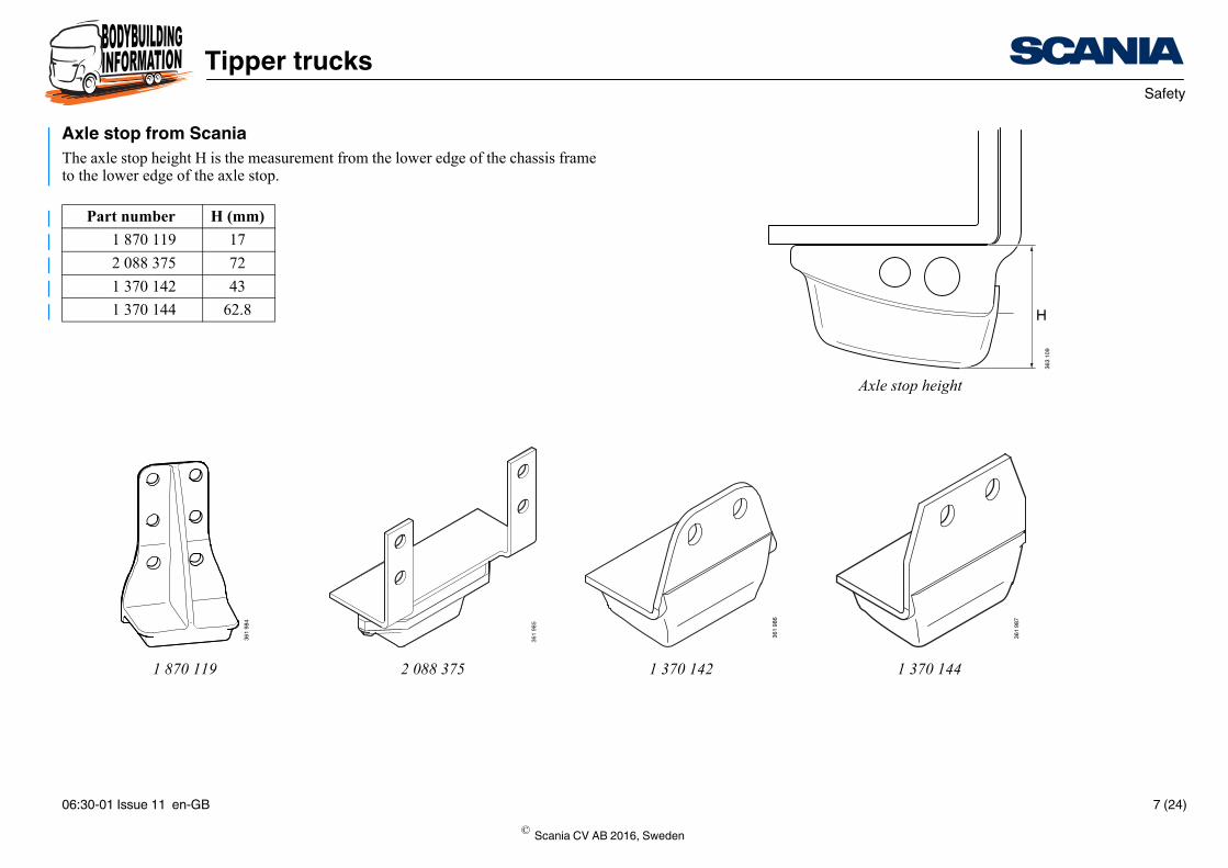
Axle stop height
361 9
86
361 9
87
Axle stop from ScaniaThe axle stop height H is the measurement from the lower edge of the chassis frame to the lower edge of the axle stop.
Part number H (mm)1 870 119 17
2 088 375 72
1 370 142 43
1 370 144 62.8
1 870 119 2 088 375
361 9
84
361 9
85
© Scania CV AB 2016, Sweden
06:30-01 Issue 11 en-GB 7 (24)

PGRT Recommendations
Tipper trucks
RecommendationsScania’s recommendations provide the best overall solution with regard to the fol-lowing factors:
• Sensitivity to frame oscillations
• Load sharing
• Driver comfort
• How the tipper body rests against the subframe or is supported in another way along the entire chassis frame.
© Scania CV AB 2016, Sweden
06:30-01 Issue 11 en-GB 8 (24)

PGRT Recommendations
Tipper trucks
More information on the design of subframes is found in the document Subframe de-sign.
More information on the choice of attachment for a specific vehicle is found in the document Selecting the subframe and attachment.
More information on body adaptation brackets is found in the document Bodywork attachment.
Attachment of the subframeSecure the subframe with the flexible brackets in the front part of the frame and with the fixed brackets at the rear axle and in the rear overhang. The number of flexible brackets is determined by the driving conditions and should be 3 brackets or more. It must be fixed brackets above the driving rear axle and bogie.
The front section of the subframe must be able to move laterally when the frame is subjected to torsional movements.
IMPORTANT!
The subframe must rest on the entire surface of the chassis frame as the friction be-tween the surfaces dampens any frame oscillations.
© Scania CV AB 2016, Sweden
06:30-01 Issue 11 en-GB 9 (24)

PGRT Recommendations
Tipper trucks
Dimensioning of the subframeThe tables show the recommended dimensions for the subframe side members for different chassis frames.
Trucks with chassis frame F950:
Trucks with chassis frame F957 or F958:
Ix = Minimum surface moment of inertia per beam.
HxWxT = height, width and thickness (for subframe with U-profile).
The data on surface moment of inertia assumes that the subframe is made of steel and has a minimum yield point of 310 N/mm2.
Rear overhangDuring rear dumping the rear overhang is subjected to extremely high stresses. This places great strain on subframe rigidity and design in this section.
Operation HxWxD (mm) Ix (cm4)
Very light 110x80x6 290
Light 110x80x8 380
Operation HxWxD (mm) Ix (cm4)
Medium 140x80x6 800
Heavy 160x80x8 900
© Scania CV AB 2016, Sweden
06:30-01 Issue 11 en-GB 10 (24)
PGRT Recommendations
Tipper trucks
600 327
097
800
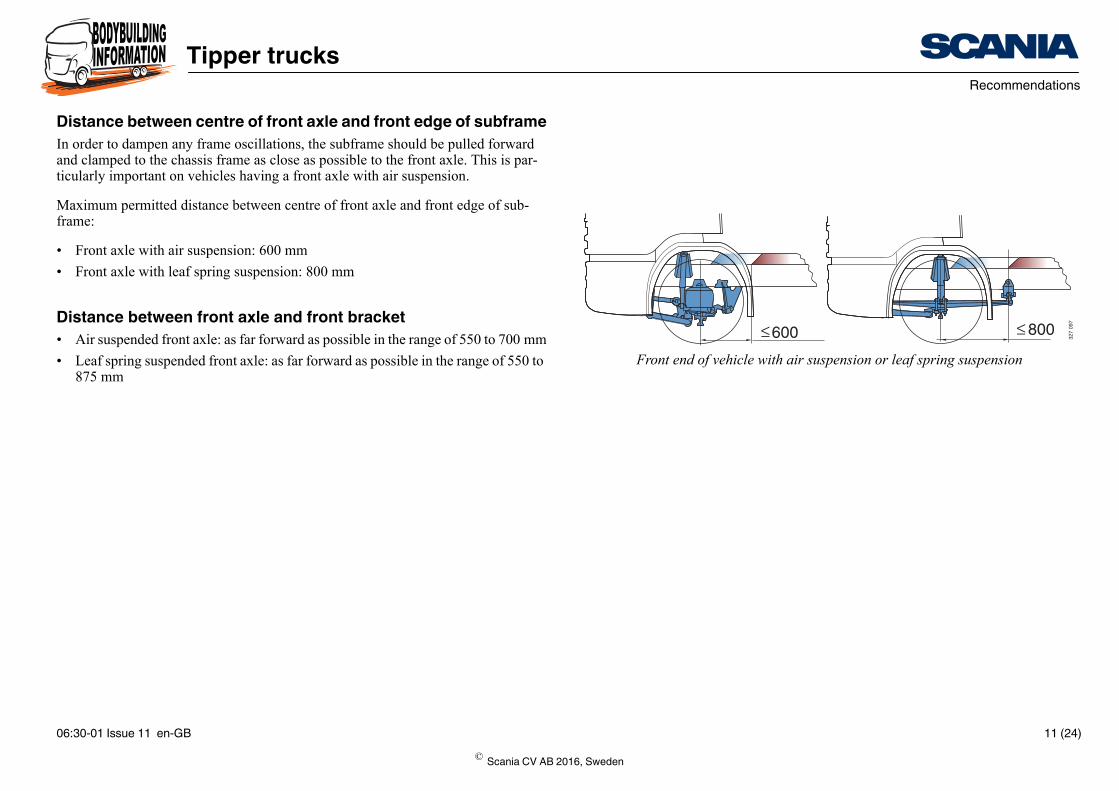
Front end of vehicle with air suspension or leaf spring suspension
Distance between centre of front axle and front edge of subframeIn order to dampen any frame oscillations, the subframe should be pulled forward and clamped to the chassis frame as close as possible to the front axle. This is par-ticularly important on vehicles having a front axle with air suspension.
Maximum permitted distance between centre of front axle and front edge of sub-frame:
• Front axle with air suspension: 600 mm
• Front axle with leaf spring suspension: 800 mm
Distance between front axle and front bracket• Air suspended front axle: as far forward as possible in the range of 550 to 700 mm
• Leaf spring suspended front axle: as far forward as possible in the range of 550 to 875 mm
© Scania CV AB 2016, Sweden
06:30-01 Issue 11 en-GB 11 (24)

PGRT Recommendations
Tipper trucks
More information on location of the brackets is found in the documents Selecting the subframe and attachment and Bodywork attachment.
353 8
96
1 870
8500000
875 A A A 650
1 870
850600200
Examples of attachmentsDimension A in the example illustrations must not exceed 900 mm.
The measurements in the illustrations are only examples and are vehicle specific.
875 A A A
1 030
300 350A 875 A A 650 62
© Scania CV AB 2016, Sweden
06:30-01 Issue 11 en-GB 12 (24)
PGRT Recommendations
Tipper trucks
347 7
28
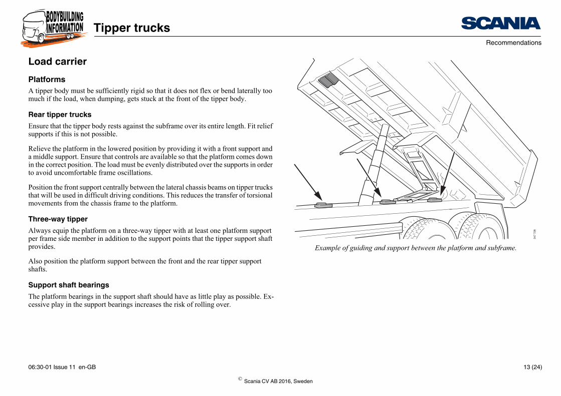
Example of guiding and support between the platform and subframe.
Load carrierPlatformsA tipper body must be sufficiently rigid so that it does not flex or bend laterally too much if the load, when dumping, gets stuck at the front of the tipper body.
Rear tipper trucksEnsure that the tipper body rests against the subframe over its entire length. Fit relief supports if this is not possible.
Relieve the platform in the lowered position by providing it with a front support and a middle support. Ensure that controls are available so that the platform comes down in the correct position. The load must be evenly distributed over the supports in order to avoid uncomfortable frame oscillations.
Position the front support centrally between the lateral chassis beams on tipper trucks that will be used in difficult driving conditions. This reduces the transfer of torsional movements from the chassis frame to the platform.
Three-way tipperAlways equip the platform on a three-way tipper with at least one platform support per frame side member in addition to the support points that the tipper support shaft provides.
Also position the platform support between the front and the rear tipper support shafts.
Support shaft bearingsThe platform bearings in the support shaft should have as little play as possible. Ex-cessive play in the support bearings increases the risk of rolling over.
© Scania CV AB 2016, Sweden
06:30-01 Issue 11 en-GB 13 (24)

PGRT Recommendations
Tipper trucks
347
736
347
735
Tipping cylinderTipping cylinder locationThe tipping cylinder must be placed in front of the tipper body’s centre of gravity. Placement behind would cause the tipping cylinder to try to lift the tipper body’s rear end.
The longitudinal position of the tipping cylinders is determined by the following fac-tors:
• The length of the platform
• The load
• Type of tipper
Improve tipper stability for rear dumping:
• Place the attachment of the tipping cylinder or tipping cylinders as far forward as possible in the chassis frame.
• Use stabilising front cylinders with bearing that permit movement only in the tip-ping direction.
© Scania CV AB 2016, Sweden
06:30-01 Issue 11 en-GB 14 (24)

PGRT Recommendations
Tipper trucks
347
745
Attachment in the subframe
Attachment of single tipping cylinderSecure the tipping cylinder with its attachment in the subframe.
Attachment of double external tipping cylindersScrew the cylinder brackets in place in the ribs on the subframe’s frame members.
Fit a strong U-profile crossmember between both tipping cylinder brackets. This pre-vents torsional movement and an asymmetrical load.
Note:The tipping cylinders must not be attached to frame member flanges.
© Scania CV AB 2016, Sweden
06:30-01 Issue 11 en-GB 15 (24)
PGRT Recommendations
Tipper trucks
1
2
304
871
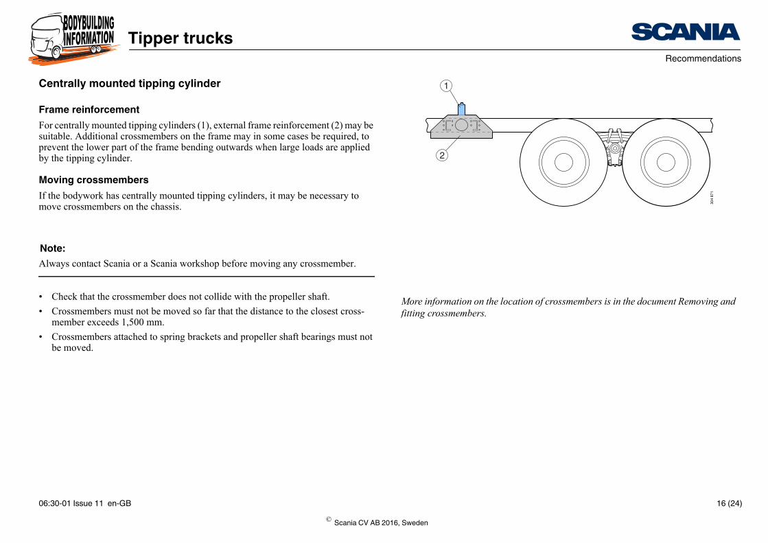
More information on the location of crossmembers is in the document Removing and fitting crossmembers.
Centrally mounted tipping cylinder
Frame reinforcementFor centrally mounted tipping cylinders (1), external frame reinforcement (2) may be suitable. Additional crossmembers on the frame may in some cases be required, to prevent the lower part of the frame bending outwards when large loads are applied by the tipping cylinder.
Moving crossmembersIf the bodywork has centrally mounted tipping cylinders, it may be necessary to move crossmembers on the chassis.
Note:Always contact Scania or a Scania workshop before moving any crossmember.
• Check that the crossmember does not collide with the propeller shaft.
• Crossmembers must not be moved so far that the distance to the closest cross-member exceeds 1,500 mm.
• Crossmembers attached to spring brackets and propeller shaft bearings must not be moved.
© Scania CV AB 2016, Sweden
06:30-01 Issue 11 en-GB 16 (24)
PGRT Recommendations
Tipper trucks
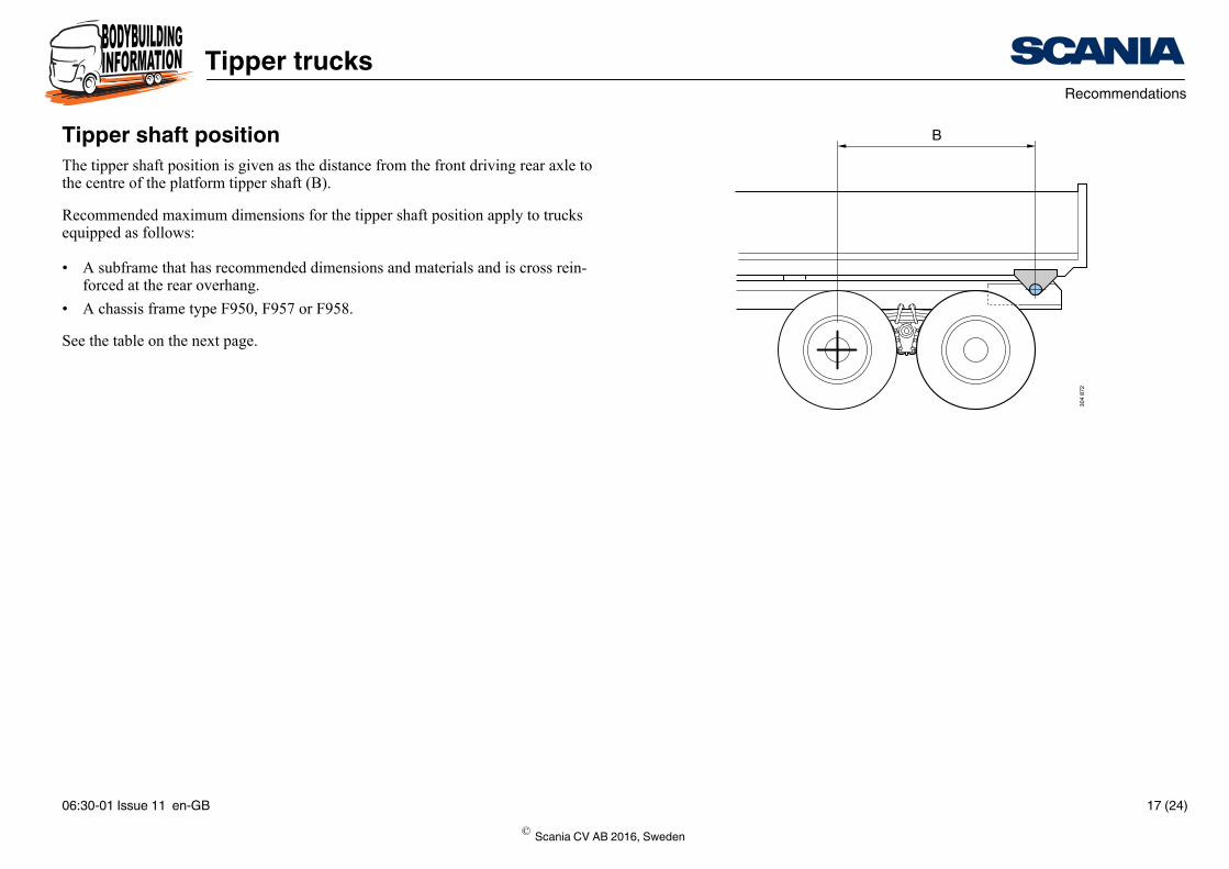
B
304
872
Tipper shaft positionThe tipper shaft position is given as the distance from the front driving rear axle to the centre of the platform tipper shaft (B).
Recommended maximum dimensions for the tipper shaft position apply to trucks equipped as follows:
• A subframe that has recommended dimensions and materials and is cross rein-forced at the rear overhang.
• A chassis frame type F950, F957 or F958.
See the table on the next page.
© Scania CV AB 2016, Sweden
06:30-01 Issue 11 en-GB 17 (24)
PGRT Recommendations
Tipper trucks
position
lity)
2,350 mm if there is good
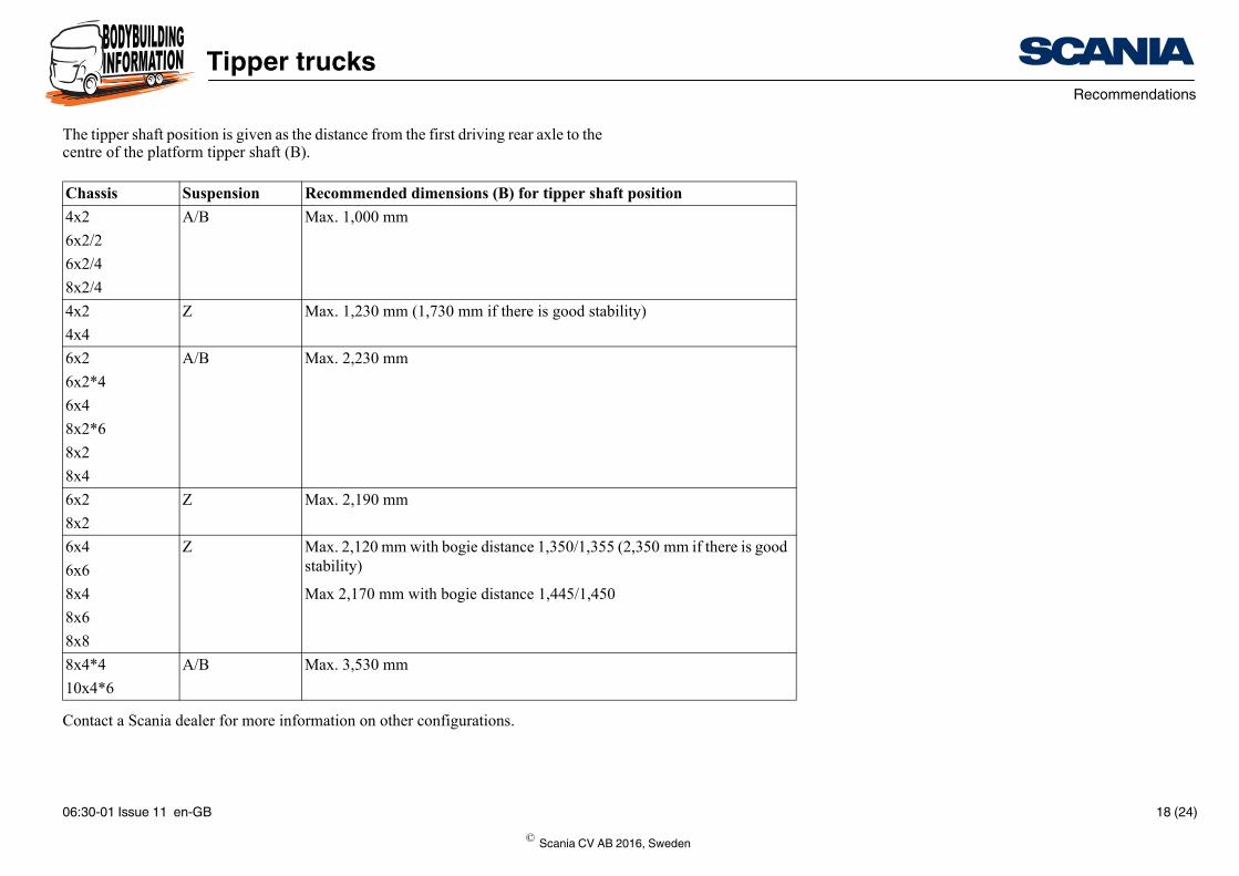
The tipper shaft position is given as the distance from the first driving rear axle to the centre of the platform tipper shaft (B).
Contact a Scania dealer for more information on other configurations.
Chassis Suspension Recommended dimensions (B) for tipper shaft4x2 A/B Max. 1,000 mm
6x2/2
6x2/4
8x2/4
4x2 Z Max. 1,230 mm (1,730 mm if there is good stabi
4x4
6x2 A/B Max. 2,230 mm
6x2*4
6x4
8x2*6
8x2
8x4
6x2 Z Max. 2,190 mm
8x2
6x4 Z Max. 2,120 mm with bogie distance 1,350/1,355 (stability)6x6
8x4 Max 2,170 mm with bogie distance 1,445/1,450
8x6
8x8
8x4*4 A/B Max. 3,530 mm
10x4*6
© Scania CV AB 2016, Sweden
06:30-01 Issue 11 en-GB 18 (24)
PGRT Stability improvement
Tipper trucks
21
304
873
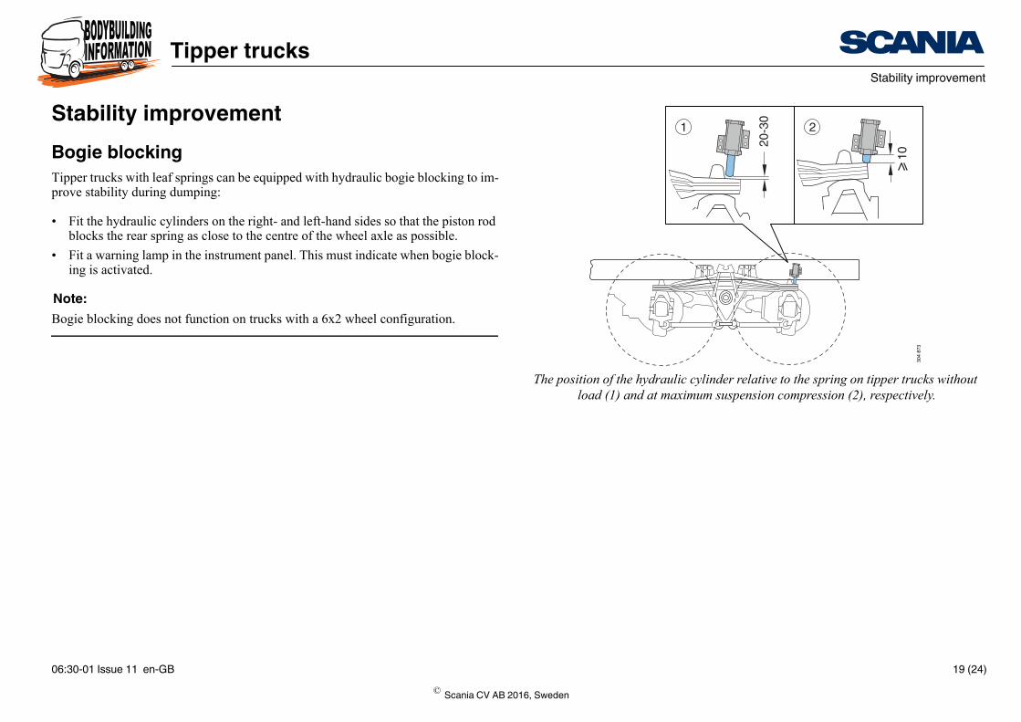
The position of the hydraulic cylinder relative to the spring on tipper trucks without load (1) and at maximum suspension compression (2), respectively.
Stability improvementBogie blockingTipper trucks with leaf springs can be equipped with hydraulic bogie blocking to im-prove stability during dumping:
• Fit the hydraulic cylinders on the right- and left-hand sides so that the piston rod blocks the rear spring as close to the centre of the wheel axle as possible.
• Fit a warning lamp in the instrument panel. This must indicate when bogie block-ing is activated.
Note:Bogie blocking does not function on trucks with a 6x2 wheel configuration.
© Scania CV AB 2016, Sweden
06:30-01 Issue 11 en-GB 19 (24)
PGRT Stability improvement
Tipper trucks
304
874
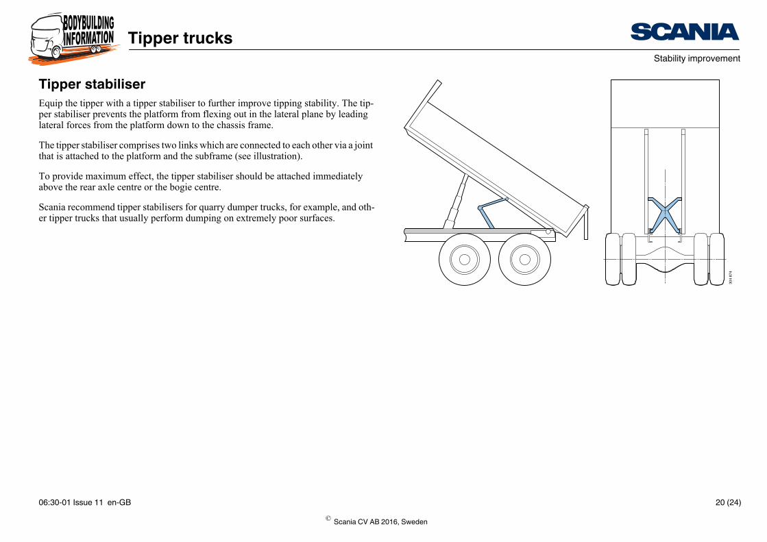
Tipper stabiliserEquip the tipper with a tipper stabiliser to further improve tipping stability. The tip-per stabiliser prevents the platform from flexing out in the lateral plane by leading lateral forces from the platform down to the chassis frame.
The tipper stabiliser comprises two links which are connected to each other via a joint that is attached to the platform and the subframe (see illustration).
To provide maximum effect, the tipper stabiliser should be attached immediately above the rear axle centre or the bogie centre.
Scania recommend tipper stabilisers for quarry dumper trucks, for example, and oth-er tipper trucks that usually perform dumping on extremely poor surfaces.
© Scania CV AB 2016, Sweden
06:30-01 Issue 11 en-GB 20 (24)
PGRT Tipper trucks without a subframe
Tipper trucks
More information on preparations for tipper trucks is found under Factory-fitted op-tion packages.
329
838
Min 10 mm
330
237
Min 75 mm
Min 10 mm
Min 610 mm
330
238
Min 75 mm
Min 10 mm
Min 610 mm
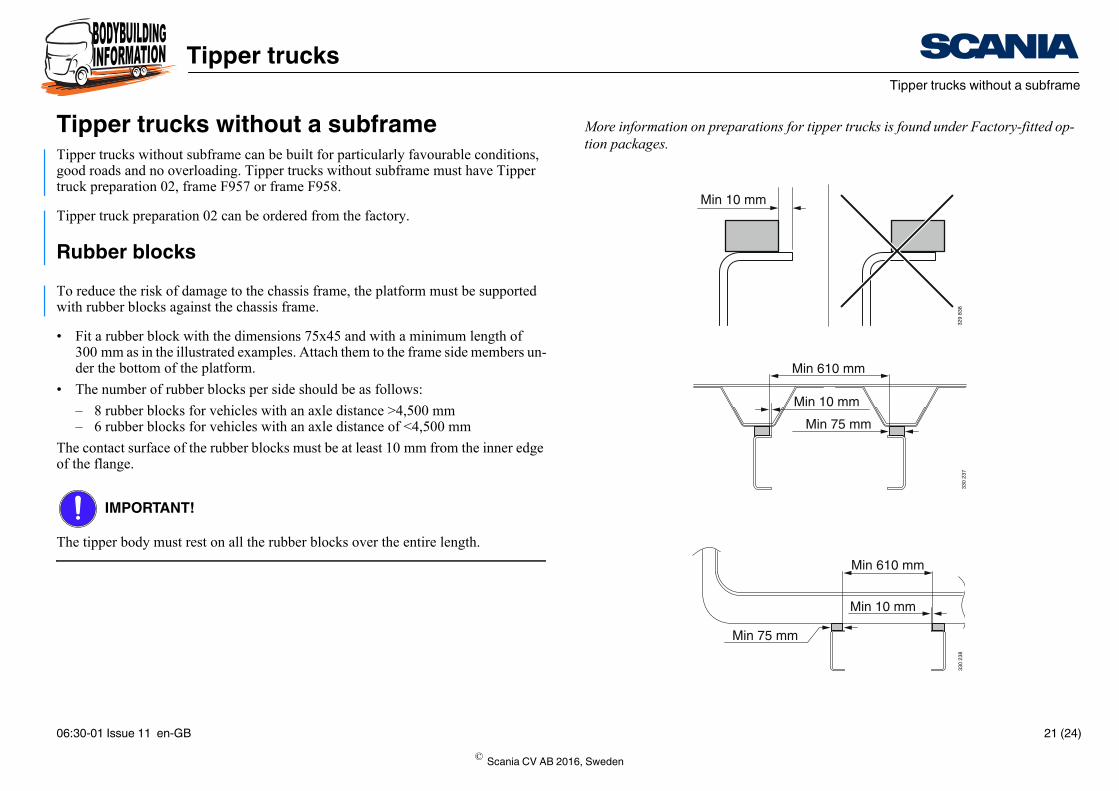
Tipper trucks without a subframeTipper trucks without subframe can be built for particularly favourable conditions, good roads and no overloading. Tipper trucks without subframe must have Tipper truck preparation 02, frame F957 or frame F958.
Tipper truck preparation 02 can be ordered from the factory.
Rubber blocksTo reduce the risk of damage to the chassis frame, the platform must be supported with rubber blocks against the chassis frame.
• Fit a rubber block with the dimensions 75x45 and with a minimum length of 300 mm as in the illustrated examples. Attach them to the frame side members un-der the bottom of the platform.
• The number of rubber blocks per side should be as follows:
– 8 rubber blocks for vehicles with an axle distance >4,500 mm– 6 rubber blocks for vehicles with an axle distance of <4,500 mm
The contact surface of the rubber blocks must be at least 10 mm from the inner edge of the flange.
IMPORTANT!
The tipper body must rest on all the rubber blocks over the entire length.
© Scania CV AB 2016, Sweden
06:30-01 Issue 11 en-GB 21 (24)
PGRT Tipper trucks without a subframe
Tipper trucks
150 150
400 400
361 9
88
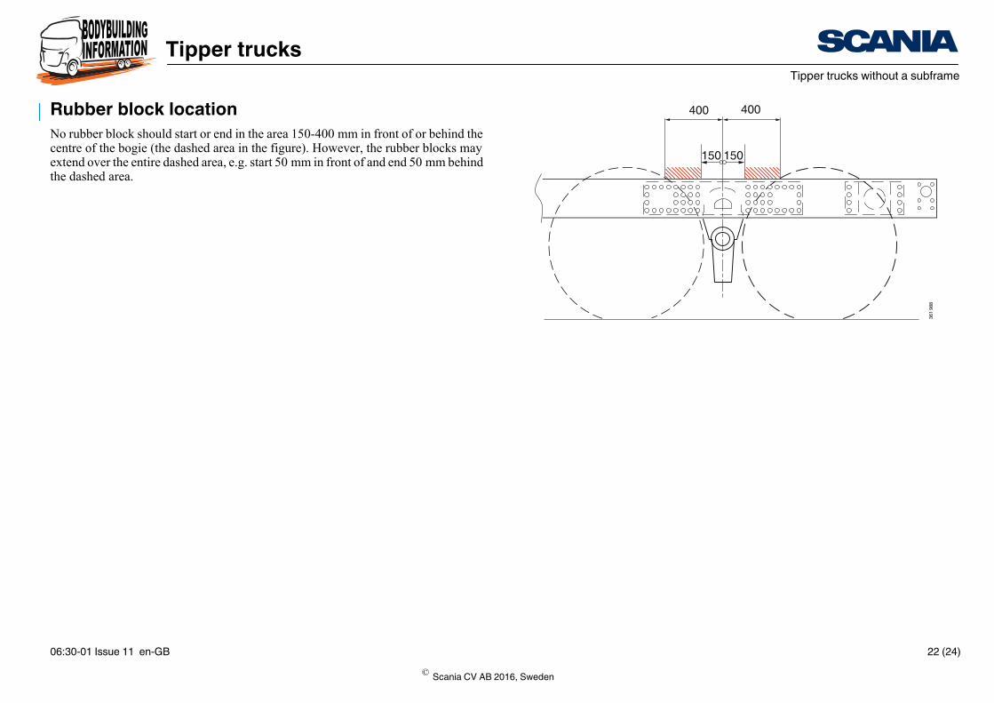
Rubber block locationNo rubber block should start or end in the area 150-400 mm in front of or behind the centre of the bogie (the dashed area in the figure). However, the rubber blocks may extend over the entire dashed area, e.g. start 50 mm in front of and end 50 mm behind the dashed area.
© Scania CV AB 2016, Sweden
06:30-01 Issue 11 en-GB 22 (24)

PGRT Tipper trucks without a subframe
Tipper trucks
g locations for the rubber blocks are recommended (all dimensions in
AD A B,900 4,550 3,700
,100 4,750 3,900
,300 4,950 64,100
ADDx75x45
985
1 6852 085
2 755B
A
JA 2210
1 385
359 5
03
For vehicles with Tipper truck preparation 02, frame F957 or frame F958 the followinmm):
AD A B C5,100 5712 5092 4207 D = at least 300 mm 3
5,300 5,912 5,292 4,407 4
5,500 6,112 5,492 4,607 4
ADDx75x45
CB
A
JA 2160
3 4352 735
2 0351 635
1 335935
359 5
02
© Scania CV AB 2016, Sweden
06:30-01 Issue 11 en-GB 23 (24)
PGRT Tipper trucks without a subframe
Tipper trucks
Maintenance and modificationTo minimize wear to the beam flange, continuous maintenance must be carried out.
The maintenance includes the following:
• Constant checking of rubber blocks and frame
• Renewal of worn rubber blocks
• Lubrication of tipper shaft
• Repair of excessive play in tipper shaft
IMPORTANT!
Make modifications to the position of the platform support and type in accordance with the above recommendations when wear starts on the outer part of the beam flange.
In the event of excessive wear, the frame side members must be reinforced.
© Scania CV AB 2016, Sweden
06:30-01 Issue 11 en-GB 24 (24)