timer 1 and 2 operation , pwm principles
DESCRIPTION
Timer 1 and 2 operation , PWM Principles. Timer 1 Operation. Timer 1 Control Register. Pulse Width Modulation (PWM). Generating PWM signals in Software. Generating PWM using HW (1). Generating PWM using HW (2). Timer 2 Block diagram. Timer 2 Control Register. Capture, Compare, PWM (CCP). - PowerPoint PPT PresentationTRANSCRIPT

Timer 1 and 2 operation , Timer 1 and 2 operation , PWM PrinciplesPWM Principles
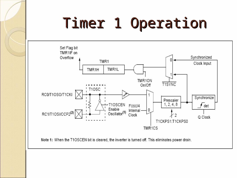
Timer 1 OperationTimer 1 Operation

Timer 1 Control RegisterTimer 1 Control Register

Pulse Width Modulation (PWM)Pulse Width Modulation (PWM)
LHon
ave VT
tV *

Generating PWM signals in SoftwareGenerating PWM signals in Software
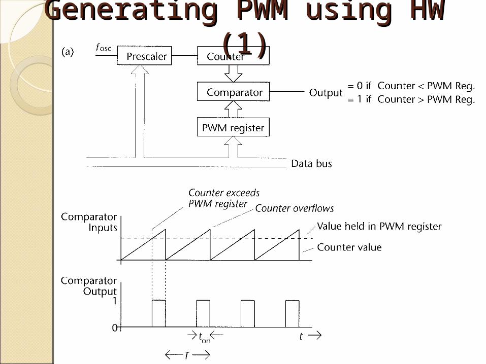
Generating PWM using HW Generating PWM using HW (1)(1)
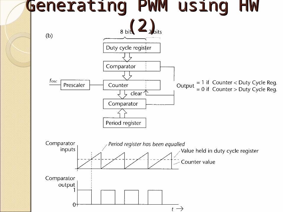
Generating PWM using HW Generating PWM using HW (2)(2)

Timer 2 Block diagram Timer 2 Block diagram

Timer 2 Control RegisterTimer 2 Control Register

Capture, Compare, PWM Capture, Compare, PWM (CCP)(CCP)
There are two CCP modules in the 16F877.Each has two eight bit registers.They modules work in conjunction with
either timer1 or timer2.They have three main modes of operation.

CCPxCON RegisterCCPxCON Register

Capture Mode OperationCapture Mode Operation

Compare Operation Compare Operation DiagramDiagram

PWM Operation DiagramPWM Operation Diagram

PWM Output at Pin RC2PWM Output at Pin RC2

PWM Calculations and PWM Calculations and SetupSetup