time sentry manual - electrex industrial solutions · introduction this section describes the...
TRANSCRIPT
TIME SENTRY MANUAL
PROGRAMMABLE LIMIT SWITCH
SERIES RC95BPS
TABLE OF CONTENTS
I INTRODUCTION / DESCRIPTION
II INSTALLATION
III PROGRAMMING
IV EXPANSION MODULES
V FAULT CHECK
VI SECURITY INPUTS
VII REMOTE CIRCULAR DISPLAY
VIII TROUBLESHOOTING
IX SPECIFICATIONS
X TROUBLESHOOTING GUIDE
PROGRAMMING GUIDE
I. INTRODUCTION / DESCRIPTION

INTRODUCTION
The RC95BPS Time Sentry is a fully self-contained, single-turn resolver-based programmable limit switch. It includes a three-digit LED display, five output relays, one fault check relay, and one brake monitor relay; it is fully programmable for the following features:
PROGRAMMABLE FEATURES
Scale Factor There is one scale factor only, permanently set to 360.
Electronic Offset Fully programmable offset to any number within the scale factor.
Motion Detector LS5 can be programmed for either limit switch or motion detect output.
Expansion Outputs Programmable to accommodate up to 29 circuits.
GENERAL DESCRIPTION
The RC95BPS Time Sentry is a fully self-contained, microcomputer-based Programmable Limit Switch (PLS) with a convenient keypad for programming each independent output circuit to open or close at the desired settings. This system allows precise position control of rotary motion.
A RC95BPS consists of a resolver-based transducer, resolver-to-programmer cable assembly, and the programmer, which provides five limit switch outputs, one fault check output, and one brake monitor output. The optional output expansion modules will add six additional limit switch outputs per module, and up to four expansion modules can be driven by the programmer, for a total of 29 limit switch outputs.
The single-turn resolver transducer generates a ratiometric analog signal representing an absolute rotary position. This ratiometric signal is converted to a digital signal at the Micro-Set. A microprocessor calculates and/or converts these signals based on user-programmed data.
As the transducer passes through the preprogrammed dwell settings, the programmer outputs can energize solenoids, relays, or solid-state circuitry to control external circuits.
The RC95BPS PLS was designed for use in rotary and/or rotary-to-linear applications. It incorporates many features for safe, efficient operation.
The completely self-contained unit can operate up to 29 independent outputs (five standard) based on the rotary position of the resolver.
It offers an on-line fault check that provides an automatic, in-process mechanism to verify that all major programmable limit switch functions are operating properly. The fault check output can be energized by activating the fault check enable input. The output is a mechanical relay with 1 N.O. and 1 N.C. contact, which remains energized during normal operation. A programmable motion detect output will energize a relay when the transducer speed exceeds the customer-preprogrammed RPM value.
Also offered is an on-line brake monitor that checks the stopping time of the machine against a customer selected preset stopping time in milliseconds, and which can be used to check the stopping distance at any point in the stroke. A dedicated output remains energized when the stop time parameters are within tolerance. An excessive stop time will cause the relay to de-energize, which could be used to stop further machine operation.

SOFTWARE ENHANCEMENTS:
Multiple Programs - Allow storage of job setups for future use. This saves time spent reprogramming and lessens the chance of programming errors when tooling is changed.
Speed-Induced Offsets - On many variable speed machines the limit switch outputs have to be adjusted when the speed increases or decreases. This automatically adjusts specified circuits based on speed.
Time-Based Outputs - Specified outputs can be programmed to turn on based on position and turn off based on time (0.01-9.99 seconds).
CONTROLLER FEATURES AND FUNCTIONS
The controller is housed in an all metal case that can be panel mounted. The controller consists of a keypad, a CPU Board, and a Power Supply I/O Board.
The following features are found on the RC95BPS Time Sentry.
Display A (3) three-digit LED readout and a 10-place bar graph are provided. The LED readout displays current angular position and/or RPM and programming details, while the bar graph shows fault check, brake monitor, program status, and limit status. NOTE: The bar graph will not display expansion board relay status.
I/O Mechanical relays, AC solid-state, and DC solid-state relays are available, and any combination can be specified. The example in the catalog shows three (3) AC and three (3) DC solid-state relays being specified. There is a fixed price adder for any combination of relays other than all mechanical (6M). The fault check relay will always be a mechanical relay regardless of the type of output relays specified. See Section IX for Relay Specifications.
II. INSTALLATION
INTRODUCTION
This section describes the installation and wiring of a standard RC95BPS Time Sentry PLS. Changes to these instructions should be made as necessary if special options and/or equipment are used.
The RC95BPS Time Sentry should be installed in an area free of water spray, corrosive gases, flying chips, or other foreign matter. The operating temperature should be between 32 and 125 degrees Fahrenheit, with less than 95% relative humidity.
MECHANICAL INSTALLATION
Mounting the RC95BPS Time Sentry PLS
The RC95BPS Time Sentry PLS is designed to be panel mounted. The face of the RC95BPS can be affected by water and/or oil spray. Provisions should be made to protect the face of the unit from spraying or splashing.

Panel cutouts, mounting holes, and sizes for each component are shown on Pages 6 and 7 of the RC95BPS catalog section.
The controller should be mounted in the appropriate panel cutout and securely bolted into place using the four (4) 3/16" diameter mounting holes.
NOTE: In instances where the RC95BPS is being mounted directly on a mechanical stamping press, care should be taken to isolate the controller from shock load and vibration.
It is always good design practice to mount the controller in the enclosure as far away from the motor starters and control relays as possible to minimize the effects of electromagnetic interference (EMI).
Interconnecting wiring also should be routed to minimize EMI coupling.
Mounting the Transducer
The proper mounting of the resolver transducer is critical to ensure the system's accuracy. There are two resolver transducers available:
(A) Standard foot mount resolver transducer. The foot mount resolver transducer should be mounted in an area free of excessive shock and vibration (as is commonly seen by mounting plates that extend over the edge of the press). The resolver transducer should be connected in a 1:1 ratio with the crank. If a double-ended cam limit switch is available, it is preferable to mount off of the rear shaft.
NOTE: The Time Sentry programmable limits are not control reliable for the clutch/brake circuits. Mechanical cam limits must be used for these circuits.
(B) Combination mechanical cam/resolver systems. Intended as bolt-in replacements to existing switches. The cam/resolver combination unit should be coupled where the existing limit switch is located. Wire and adjust the mechanical cams in accordance with the original press manufacturer's specifications and wire the resolver cable to the controller.
ELECTRICAL INSTALLATION
Introduction
The Time Sentry is designed for use in an industrial environment and incorporates extensive transient suppression circuitry. However, the same general installation rules should be followed that are used on all microprocessor-based equipment. Incoming AC lines should be from a clean power source, and lines carrying computer level signals should not be routed in the same conduit as high voltage, transient-producing circuits such as variable speed drives, welders, or DC switching circuits.
The RC95BPS PLS is only used with a single-turn resolver. Wiring for this system is shown on Drawing M3009R5. This wiring diagram is applicable for all standard RC95BPS PLS's.
WIRING INSTRUCTIONS
Attach the pre-wired plug on the resolver transducer cable to the transducer and route the shielded cable through a separate grounded (earth ground) metal conduit to the panel. Connect the mating half terminal block to the RC95BPS PLS. Be sure the shield wire is connected to Pin 1 of the 16-place connector.

When extension to the factory supplied cable is necessary, a junction box should be used to connect the wire leads and the cable shields from one cable to the other. The cable shield should be grounded at the RC95BPS Micro-Set only.
AC line voltage - 115V AC 10% 50-60 Hz - should be connected to the RC95BPS at the "AC power" terminals on the 24-place connector.
III. PROGRAMMING
SECURITY INPUT
The security input is often referred to as the "Run/Program" input. This input is located on the 16-place terminal strip and is discussed in Section VI. This input prevents unauthorized changes to the programmed functions. With the unit in the "Program" mode, all functions of the controller can be programmed. With the unit in the "Run" mode, all set points, motion detect, and other operational functions can be verified, but the programmed information cannot be changed.
INITIALIZATION
The following key commands CIR # - 9 - 9 - 5 - ENT should be entered on the keypad to clear all programmed data upon installation and PRIOR to programming. This sequence clears all programmed data. All operating parameters must be reprogrammed after using this initialization function.
SCALE FACTOR The RC95BPS is available only with a 360 degree scale factor, set permanently.
NUMBER OF OUTPUTS
Introduction
The RC95BPS comes programmed for five outputs, but it is expandable to 29 outputs. However, when using a Remote Circular Display, the maximum will be 23 outputs.
SELECTING NUMBER OF OUTPUTS
Selection of the number of outputs should be done after the system is initialized and before any other programming is done. See Section IV, Expansion Modules.
A) To program the number of outputs desired, the unit must be in the Program mode; then press CIR # - 1 - 7 - 7 - ENT. The unit will then show the number of circuits previously stored. To change the number of outputs desired, enter the number of relays in multiples of six and press ENT.

1) Valid numbers for CIR # - 1 - 7 - 7 - ENT are 6, 12, 18, 24, and 30. Remember, if using a Remote Circular Display, the maximum number of outputs is 23. (NOTE: If a number is entered that is not a multiple of six, the unit will store the next multiple of six.)
MULTI-PROGRAM
Introduction
The Multi-program feature allows the storage of multiple sets of output sequences that are preprogrammed based on the various requirements of different tooling. When dies or tooling are changed, the new program is simply called up on the keypad and all outputs are automatically set to the new output sequences. The number of available programs will vary based on the number of output limits and the number of set points programmed on each limit. A typical five-limit system with one "ON" and one "OFF" set point per output will be capable of storing twenty programs in memory.
A set point is one "CIR ON" or "CIR OFF" entry. The following formula shows the relationship between the number of output relays, the number of programs, and the number of set points available per program.
SET POINT FORMULA
set point / Programs = 1467 - 2 Number of Programs x A Where: A = 5 for 5 outputs = 6 for 11 outputs = 7 for 17 outputs = 8 for 23 outputs = 9 for 29 outputs
Set points are in whole numbers (drop decimal). Example: 12 output relays with 10 programs: S.P. = 1467 - 2 = 24.45 - 2 = 22 Set points/Program 10 x 6
The following table shows the relationship between the number of outputs, the number of programs, and the number of set points per program. The table only shows a few of the many combinations that are possible. Before programming outputs, it is advisable to verify that enough set points are available; otherwise, the number of programs may need to be reduced. A set points is one "CIR ON" or "CIR OFF" entry.
5 OUTPUTS 11 OUTPUTS 17 OUTPUTS 23 OUTPUTS 29 OUTPUTS
1/253 1/242 1/207 1/181 1/161
20/12 9/25 5/39 4/43 2/79
26/9 12/18 8/24 5/34 3/52
36/6 17/12 10/18 7/24 5/30

97/1 27/7 13/14 8/20 6/25
Number of program Resulting number of set points per program.
Programming RC95BPS PLS for Multi-program
A) Specify the number of programs desired; unit must be in the "Program" mode. Press CIR # - 7 - 7 - 0 - ENT - CIR ON - # of Programs - ENT. See Page 11 for the capabilities of your unit.
B) Upon entering the above sequence, pressing the CIR OFF key will display the maximum amount of set points per program.
NOTE: A time-based output uses up three set points.
C) CIR # - 7 - 7 - 2 - ENT will display the total number of set points available for use in the currently selected active program.
D) To display the active program, press CIR # - 7 - 7 - 1 - ENT. To change programs, with the unit in the Program mode press 0 through Highest Program Number - ENT. NOTE: Program 0 is the first program. If 10 programs were previously selected using Code 770, there will be programs 0-9.
SET POINTS
Programming New Set points
A) Unit must be in the "Program" mode.
B) Select a limit switch circuit for programming. Press CIR # - 1 through 30 - ENT. The circuit number selected cannot exceed the number of output relays specified earlier using CIR # 177. See Page 10.
NOTE: LS6 is dedicated solely to the brake monitor relay and cannot be programmed.
C) Press CIR ON - Desired Pos - ENT. This will set the selected relay turn-on point.
D) Press CIR OFF - Desired Pos - ENT. This will set the selected relay turn-off point.
1) On units where time-based circuits have been selected, the CIR OFF will be the time interval that the relay will be active once the ON set point has been reached.
E) Multiple ON and OFF set points can be programmed on each circuit. All decimal points will flash when more than one set point exists on the selected circuit.
F) An LS (Limit Switch) may not have the same value for both the ON point and the OFF point. If a value is entered that is already a set point for that LS, only the new one will be used. For example: If LS1 had an ON point at 100 and an OFF point of 100 was entered, the ON point at 100 would be deleted, and the OFF point would then take its place. Assuming that these were the only set points, the output would turn ON at 0 and OFF at 100.

The programmable limits are programmed based on "dwell on" and "dwell off" locations. The "dwell on" typically represents the location at which a selected limit turns on and the "dwell off" represents the location at which the limit turns off. The position locations for the "dwell on" and "dwell off" are based on a scale factor corresponding to the 360-degree rotation of the resolver. Example: In the foregoing example, with a 360 scale factor, a "dwell on" of 0 and a "dwell off" of 100 would like this:
0 100 359
The shaded area represents the area where the selected limit output relay is energized. Programmable limit switch outputs offer a unique function which normal rotating cam limits cannot, namely, the ability to turn a limit on or off more than once in a 360-degree cycle. Multiple dwells allow several "dwell on" and "dwell off" values to be programmed for a particular limit. Example: "Dwell on" settings of 20, 100, 200, and "dwell off" settings of 80, 180, 270 would look like the following:
0 20 80 100 180 200 270 359
Another feature of programmable limits is the ability of programming a "dwell on" or a "dwell off" only. If only a "dwell on" setting is programmed, the output will activate at the "dwell on" setting and remain on to 359 degrees. Example: "Dwell on" setting of 180 and "dwell off" not programmed will result in the following:
0 180 359
Conversely, if only a "dwell off" setting is programmed, the output will activate from 0 degrees to the "dwell off" setting. Example: "Dwell on" not programmed, "dwell off" set at 180 degrees will result in the following:
0 180 359
The programmable limits also have the ability to "shift" the dwells to turn on sooner. This can be done to compensate for mechanical lag in the devices they are controlling as the machine speed increases. (See Page 19 under "Linear Speed Offset" for more details.) Limits can also be programmed to turn off based on timed settings.
CLEAR AN EXISTING SET POINT

A) Unit must be in the "Program" mode.
B) Press CIR # - Output to be Cleared - ENT.
C) Press CIR ON or CIR OFF key until set point to be cleared is on the display.
D) Press the CLR SET key. Upon pressing the CLR SET key, the set point on the display after step C is deleted.
E) This keypad sequence must be completed once to clear an ON set point and a second time to clear the OFF set point. See Page 13, step F under the subheading "Programming New set points."
CLEAR ALL SET POINTS
There are two methods of clearing all set points. This is accomplished as follows:
A) Unit must be in the "Program" mode.
B) To clear all of the set points in the active program, press: CIR # - 9 - 1 - ENT. The active program is the program currently selected using Code 771. (See Page 12.)
-OR-
C) To clear all the set points in all programs, press: CIR # - 3 - 9 - 1 - ENT. NOTE: CIR # 91 and CIR # 391 only clear out programmed set points. They do not clear out Linear Speed ramps or change circuits that have been selected as Linear Speed or Time-Based; however, they will clear the set points programmed in these circuits.
SET POINT AVAILABILITY
Every RC95BPS PLS has a limit on the number of set points that can be stored in memory. On units with the Multi-program option, refer to Page 11 for the formula to calculate the maximum amount of set points available.
On units without Multi-program, set point availability is dependent on the number of outputs enabled.
5 Outputs = 253 Set points Available
11 Outputs = 242 Set points Available
17 Outputs = 207 Set points Available
23 Outputs = 181 Set points Available
29 Outputs = 161 Set points Available
Refer to Page 10 for the number of outputs enabled.
ELECTRONIC OFFSET

Introduction
The offset key is used to synchronize the digital display with the actual machine position. The Series RC95BPS PLS has full scale factor offset capabilities, and the offset is held in nonvolatile memory. However, to eliminate possible problems in the event that a replacement PLS is required, it is good practice to mechanically synchronize the resolver with the machine and then use the offset key to make final, fine-tune adjustments.
Programming the Electronic Offset
A) Unit must be in the "Program" mode.
B) Stop machine at a known location.
C) Press OFFSET - Actual Machine Position - ENT. After this sequence is completed, the display will change to the position entered. The display and outputs are now synchronized with the actual machine position.
MOTION DETECTOR
A programmable Motion Detect output will energize a relay when the transducer speed exceeds the customer's preprogrammed RPM value.
The motion detector is set by entering the following:
A) Unit must be in the "Program" mode.
B) The motion detect must first be enabled before you can store any values. To accomplish this, press CIR # - 5 - 5 - ENT - 0 or 1 - ENT. A one (1) will enable the motion detect circuit, and LS5 will now be your motion detect output relay. If a zero (0) is entered, the motion detect feature is disabled and LS5 will function as a normal limit switch.
C) To set the value at which the motion detect relay energizes, press CIR # - 1 - 7 - 6 - ENT - RPM Value - ENT.
NOTE: A CIR # 176 can only be entered if the motion detect option is enabled.
POWER-UP IN POSITION OR RPM
The RC95BPS can power up displaying either Position or RPM data.
The power-up mode is programmed by entering the following:
A) Unit must be in the "Program" mode.
B) Press CIR # - 1 - 6 - 3 - ENT - 0 or 1 - ENT. If a zero (0) is entered, positional data will be displayed upon power-up; if a one (1) is entered, the unit will power up displaying RPM.
DECIMAL POINT PROGRAMMING

A continuous, non-floating decimal point may be programmed on the display. If a scale factor is selected that needs a decimal point in order to properly display its resolution in engineering units, the following 50 series codes are used:
50 - No decimal point; clears existing decimal point 123
51 - Tenths 12.3
52 - Hundredths 1.23
To program a decimal point enter the following:
A) Unit must be in the "Program" mode.
B) Press CIR # - 50 or 51 or 52 - ENT.
Example: CIR #50 = 123
CIR #51 = 12.3
CIR #52 = 1.23
ENABLE / DISABLE OUTPUTS
During setup, the outputs may be enabled or disabled. When outputs are selected to be disabled, the status LED's and the relays will be OFF. The unit must be in the Program mode to disable the outputs; as soon as the unit is switched to the Run mode, the outputs will be enabled.
The enable/disable feature is programmed as follows:
A) Unit must be in the "Program" mode.
B) Press CIR # - 380 or 381 - ENT.
CIR # 380 Enables the Outputs.
CIR # 381 Disables the Outputs.
NOTE: If you try to disable the outputs in the Run mode the unit will display "EEE."
LINEAR SPEED OFFSET
This feature allows limit switch outputs one through five to be programmed to automatically advance and retard as machine velocity varies. The number of circuits affected by speed offset, the amount of offset, and the RPM range over which the offset develops are all keypad programmable. The amount of offset per RPM change will be the same for all outputs selected for this type of operation. This feature is used to compensate for the mechanical lag in machine controls.
The 16-step linear speed offset feature allows up to 16 different offset steps to be selected and a different amount of positive or negative (advance or retard) offset to be programmed between each of the sixteen steps.

Access Codes 501 through 516 are used to select the successive steps that define a ramp between the various offset values. That is, Code 501 is used to access and program the ramp between 0 RPM and the RPM value assigned to the first step; Code 502 is used to access and program the ramp between the RPM value of the first step and the RPM value assigned to the second step; and so on.
After using the access code to call up a step for programming, the CIR ON key is pressed, followed by the total amount of offset (from zero offset) to be applied to the circuit at the specified RPM value. The CIR OFF key is pressed next, followed by the RPM value of that step. The programmed offset value will be the total amount of offset being applied to the circuits from their zero offset starting values. This allows the circuits to be advanced or retarded between any two steps. (Refer to Pages 21 and 22 for programming sequence.)
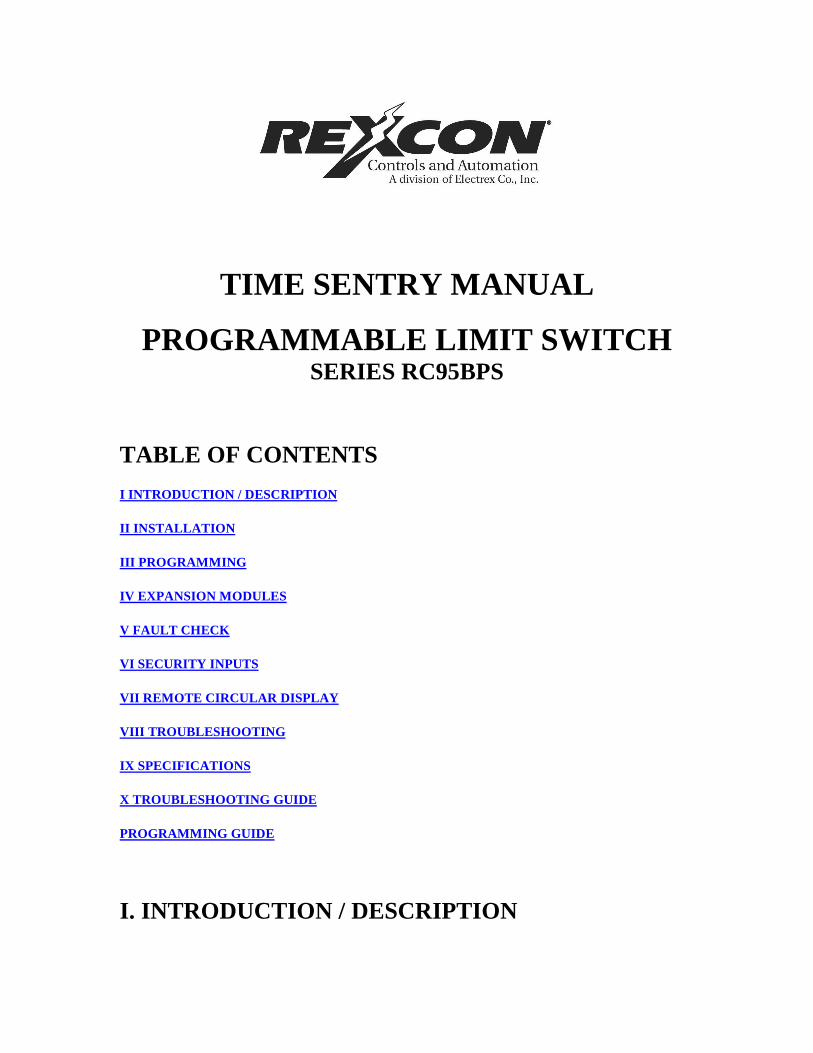
The graph above shows an example of five steps of linear offset in which the output circuits remain the same in the first step, then are being advanced in the next two steps, retarded between the third and fourth, and remaining unchanged between the fourth and fifth. The first step (501) is programmed so that the outputs will not be affected until after 20 RPM. Then the second step (502) is programmed to linearly advance the selected outputs by 20 degrees between 20 and 60 RPM. Circuits originally programmed to turn on at 150 degrees and off at 350 degrees will be turning on at 130 degrees and off at 330 degrees while at 60 RPM. The third step (503) is programmed to advance these same outputs to a total of 50 degrees as RPM rises between 60 and 100 RPM.
The example circuit mentioned above that was originally programmed to turn on at 150 degrees and off at 350 degrees will now be turning on at 100 degrees and off at 300 degrees while at 100 RPM. The fourth step (504) is programmed to retard the circuits back to a total of 30 degrees as RPM continues to rise from 100 to 140 RPM. The example circuit, originally programmed to turn on at 150 degrees and off at 350 degrees is now turning on at 120 degrees and off at 320 degrees while running at 140 RPM. The fifth step (505) is programmed to maintain a fixed 30 degrees of total offset between 140 and 200 RPM.
NORMAL PLS DWELL
0 150 350 359
1ST COMPENSATION AT 20 RPM
0 150 350 359
2ND COMPENSATION AT 60 RPM
0 130 330 359
3RD COMPENSATION AT 100 RPM
0 100 300 359
4TH COMPENSATION AT 140 RPM
0 120 320 359
5TH COMPENSATION AT 200 RPM
0 120 320 359
The offset (advance or retard) is applied linearly between each step, and the offset follows the same curve as RPM decreases. Example: At 80 RPM offset value would be 35 o.
PROGRAMMING RC95BPS PLS FOR LINEAR SPEED
A) Unit must be in the "Program" mode.
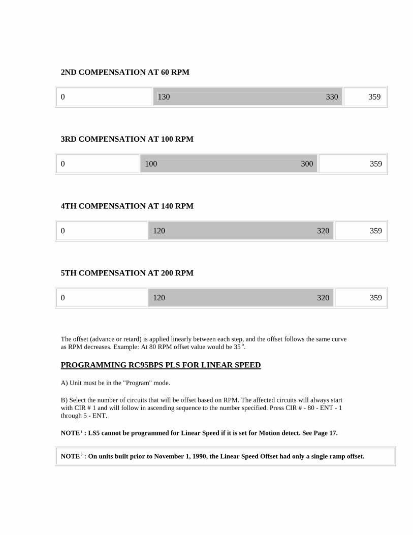
B) Select the number of circuits that will be offset based on RPM. The affected circuits will always start with CIR # 1 and will follow in ascending sequence to the number specified. Press CIR # - 80 - ENT - 1 through 5 - ENT.
NOTE 1 : LS5 cannot be programmed for Linear Speed if it is set for Motion detect. See Page 17.
NOTE 2 : On units built prior to November 1, 1990, the Linear Speed Offset had only a single ramp offset.

CIR # - 81 - ENT - CIR ON = Offset Amount
CIR # - 81 - ENT - CIR OFF = RPM Value
Codes 501-516 will result in a programming error on this older software.
C) Starting with Circuit 501, program the amount of offset and RPM point for the first offset ramp. Next use Circuit 502 to program both values for the second offset ramp. Continue with Circuit 503 and onward in ascending order until all desired ramps are programmed.
1) CIR # - 501 through 516 - ENT - CIR ON - (Specify the total amount of offset from the original output settings) - ENT
2) CIR # - 501 through 516 - ENT - CIR OFF - (Specify the RPM at which the above specified amount of offset occurs.)
NOTE: If "CIR # 501" - "CIR OFF" is set to zero, all linear speeds will be disabled.
MINIMUM SPEED DISABLE
The Minimum Speed Disable sets the minimum speed at which the Linear Speed will affect the outputs. Below the programmed speed the Linear Speed outputs will not be enabled.
The Minimum Speed feature is programmed as follows:
A) Unit must be in the "program" mode.
B) Press CIR # - 85 - ENT - RPM Value - ENT. This sets the Minimum Speed at which the Linear Speed will affect the outputs. Below the programmed speed, the Linear Speed outputs will not be enabled.
TIME-BASED OUTPUTS
In instances where it is desirable to have an output actuate based on crank position and turn off based on time, we offer time-based limits. Examples of areas where time-based limits are applicable include lubricators and air blow-off limits. Even if the press stopped in the limit "dwell' area, it would only stay energized for a specific time period, eliminating potential waste. Circuits one through five can be selected for this type of operation. Circuits cannot be programmed for Linear Speed Offset and Time-Based outputs at the same time; thus the total combined number of Linear Speed Offset and Time-Based outputs cannot exceed five.
NOTE: CIR # 301 through 305 only enable the circuit so that it can be programmed for a Time-Based output. After Time-Based circuits are enabled, refer to Page 12 steps C & D for Programming Set points.
The Time-Based feature is programmed as follows:
A) Unit must be in the "Program" mode.
B) Press CIR # - 301 through 305 - ENT - 0 or 1 - ENT.
CIR #301 represents CIR #1, CIR #302 represents CIR #2, etc. A zero (0) after CIR # 301-305 means that the circuit will function as a normal limit switch as outlined on Page 17; however if a one (1) is entered in after CIR # 301-305, it means that the circuit is to be set up for a position ON and a timed OFF output.
C) This sequence only enables or disables LS1 through LS5 for Time-Based operation. After an LS is enabled as a Time-Based circuit, follow normal programming instructions. See Page 12 steps C & D under Programming Set points.
NOTE: If LS5 is set as a motion detector, it cannot be set for Time-Based.
D) A Time-Based output may only have one CIR ON and one CIR OFF set point. This output will turn on based upon the CIR ON position data and will turn OFF based upon the CIR OFF time data, which is displayed and programmed in 0.01 second increments. A Time-Based output uses three set points. See Page 11.
E) Outputs 1 through 5 may incorporate Linear Speed Offset or may be Time-Based. However, no output can be both. In addition, LS5 may be selected to be a motion detect output. If two or three types of outputs are required, first select the number of Linear Speed circuits required (CIR 80) and then individually select the Time-Based outputs and Motion Detect output.
Example: Outputs 1 & 2 Linear Speed
CIR = 80 - ENT - 2 - ENT
Outputs 3 & 4 Time-Based
CIR = 303 - ENT - 1 - ENT
CIR = 304 - ENT - 1 - ENT
Output 5 Motion Detect
CIR = 55 - ENT - 1 - ENT
BRAKE MONITOR OPERATIONAL DESCRIPTION
The RC95BPS Brake Monitor PLS offers an on-line monitor which checks the stopping time of the press against a customer selected preset stopping time in milliseconds, and can be used to check the stopping distance at any point during the stroke.
With keypad commands, the digital readout will display the stopping time (CIR # 174) or the stopping distance (degrees) (CIR # 175) of each cycle. If the time from de-energization of the press clutch voltage to stopping the ram exceeds a customer's programmed value, the brake monitor output relay will de-energize which can be used to stop further press operation. This output can be reset by momentarily opening and then closing the fault check input. Please note that the brake monitor system operates independently of the fault check system but both use the fault check input to reset their individual faults. Opening the fault check input will de-energize the fault and brake monitor output relays allowing the user to verify that these outputs are operating properly and have not been hardwired.
NOTE: In efforts to make the brake monitor fail-safe we have changed the brake monitor circuit so that if you see motion without seeing the brake input, a brake fault will occur.

WIRING
Wire the programmer per Drawing M3009R5. In this drawing, relay LS6 is the brake monitor relay. It is normally energized (N.O. contact is closed and N.C. contact is open) and de-energized on a fault condition. Operating in this manner a disconnected wire or disconnected relay will indicate a fault condition.
Relay LS5 is either a standard LS output or the motion detect output, as selected by the customer. If operating as a motion detect output, the relay will energize when the transducer speed is greater than the customer programmed RPM value.
The brake monitor calculates stopping time by monitoring the time span between the clutch disengagement and the press's coming to a complete stop. The system begins this timing sequence when it sees the isolated contact, wired between input terminals 14 and 15, open. This isolated contact can be the contact of an existing relay in your control circuit or it can be provided by an optional Brake Monitor input Relay as shown on the next page. The contact of the brake monitor input relay must open when the clutch disengages, and all will ring between its isolated contact and terminals 14 and 15 of the RC95BPS programmer must be protected from induced electrical noise.
PROGRAMMING AND MONITORING

To monitor press stopping time, press CIR # - 174 - ENT. Stopping time will be displayed in milliseconds from 001 to 999. Three decimal points indicate a stopping time in milliseconds, a single decimal point, two places to the left, will indicate a stopping time in seconds to one hundredth of a second. If the customer's preset stopping time is exceeded, the display and decimal(s) will flash. They will continue to flash until the brake monitor output has been reset.
To monitor press stopping angle, press CIR # - 175 - ENT. Stopping distance will be displayed in degree increments. If the stopping time is exceeded while in the stopping angle mode, the display will flash. It will continue to flash until the brake monitor relay has been reset.
When operating in either of the above modes, the display will maintain the stopping data until initiation of the next timing cycle. At this point, the display will indicate dashes until new data is available. Pressing of the POS or RPM keys will return the display from this operating mode.
To program the maximum acceptable stopping time, press CIR # - 173 - ENT. The time data can be programmed from 001 to 999 milliseconds. If the programmed stopping time is exceeded, the brake monitor output (LS6) will de-energize until the fault check input is opened and then closed again.
Note: If you are using the fault check option, the fault check relay will cycle OFF/ON when the brake fault output is reset.
Programming the Maximum Stopping Time
A) Unit must be in the "Program" mode.
B) Press CIR # - 1 - 7 - 3 - ENT - Maximum Stopping Time - ENT. This sets the maximum allowable stopping time in .001 second intervals.
If the time required to stop following the loss of the brake monitor contact exceeds the brake monitor stopping time, then the error output LS6 is de-energized.
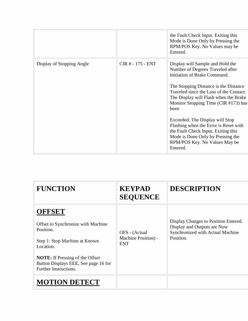
Display of Stopping Time
A) Press CIR # - 1 - 7 - 4 - ENT. The display will sample and hold the stopping time of each press stroke. The stopping time is displayed in milliseconds. A single decimal in the left-most position will indicate that a stopping time is in seconds. The display will flash when the brake monitor stopping time (CIR # 173) has been exceeded. The display will stop flashing when the error is reset with the fault check input. Exiting this mode is done only by pressing the RPM/POS key. No values may be entered.
Display of Stopping Angle
A) Press CIR # - 1 - 7 - 5 - ENT. The display will sample and hold the number of degrees traveled after initiation of the brake command.
The stopping distance is the distance traveled since the loss of the contact. The display will flash when the brake monitor stopping time (CIR # 173) has been exceeded. The display will stop flashing when the error is reset with the fault check input. Exiting this mode is done only by pressing the RPM/POS key. No values may be entered.

IV. EXPANSION MODULES
EXPANSION MODULES
The RC95BPS PLS provides six outputs. A RC95E Expansion Module is required for each additional six outputs desired up to a total of 30 outputs, or four expansion modules (units with Remote Circular Displays may use only up to 23 outputs total, or three expansion modules). The circuit location of each expansion module is defined by the location of a two-pin jumper on an eight-pin block in the upper left corner of the module. This jumper must be installed for the expansion module to operate. Two pairs of pins, located in the lower right corner of the expansion module, should be jumped on only the last module in the wiring group. However, if a Remote Circular Display is being used, do not install these jumpers. Remove both jumpers from all intermediate expansion modules. Refer to Drawing Number M300R95 for additional expansion module wiring information. Each expansion module is provided with a full set of terminal strip designation decals. To avoid confusion, the appropriate decals should be installed along the output terminals, based on the location of the output selection jumper outlined below.
V. FAULT CHECK
FAULT CHECK
The fault check option provides an automatic in-process self-diagnostic mechanism to verify that all PLS functions are operating properly.
The fault check option will detect and disable system operation in the event of any of the following problems:
1. Disconnected or severed resolver cable.
2. Open or shorted resolver signals.
3. Resolver excitation failure.
4. Resolver-to-digital converter or associated electronic failure.
5. Microprocessor or 5 volt power supply failure.
Non system-type faults, such as individual output failures, will not be sensed. It is recommended that the fault check output be used as an "operate enable"-type signal. Loss of this output should immediately stop the process which is being controlled.
The fault check input may be operated by an isolated contact, current sourcing, or current sinking device 5V DC at 10mA.
A normally closed, momentary open contact button can be wired per Drawing M300R95 to activate the fault check circuit, and it will provide a method of resetting the fault output after a fault condition has been sensed.

To reset the fault check output after the fault condition has been cleared, the fault reset input must be deactivated (open circuit) and then reactivated. Cycling the fault reset input will cycle the fault check relay to verify that the fault check output is operating properly.
NOTE: If the fault check inputs are not wired, the display will still show when there is a fault and the outputs will be disabled, but it will not lock on the fault. However, if the fault check inputs are wired as per Drawing M300R95, then upon seeing a fault the fault check relay will drop out and all outputs will shut off until the fault is fixed and the fault check input is reset.
PLS OUTPUT STATUS ON FAULT CONDITIONS
1) If a fault condition is detected, ALL limit switch outputs will turn off and the display will show the following:
EE0 - Resolver Not Plugged In or Resolver Primary Open
EE1 - Resolver Secondary S1-S3 Open or Shorted
EE2 - Resolver Secondary S2-S4 Open or Shorted
EE3 - Resolver Shorted - Primary Winding or Resolver Excitation Fault
EE4 - Electronic Transducer Tracking Fault
No Message Microprocessor or 5 Volt Power Supply Failure
The message will remain on the display and the outputs will be off until the problem is corrected and the fault reset button is pressed and released to reactivate the fault output and return the display and outputs to their normal operation.
2) If the fault condition is the result of a microprocessor failure or lockup, the state of the limit switch output circuits cannot be predicted. However, the fault check output will turn off until the fault is cleared and the fault reset button is pressed and released. Removal and reapplication of power to the PLS system may clear a locked-up condition.
VI. SECURITY INPUTS
RUN / PROGRAM SECURITY INPUTS
The Run/Program security inputs may be operated by an isolated contact, current sourcing, or a current sinking device, 5V DC @ 10 mA. Refer to Drawing M3009R5 for wiring options.
NOTE 1: The RC95BPS PLS cannot be programmed until the security input has been enabled by means of connections from Pin 9 (+5V DC) to Pin 10
(Security +) input and from Pin 11 (Security -) input to Pin 14 (GND).

NOTE 2: If the Run/Security program is not needed (always in the Program mode) install jumper wires from Pin 9 (+5V DC) to Pin 10 (Security +) and from Pin 11 (Security -) to Pin 14 (GND) on the 16-place resolver connector.
VII. REMOTE CIRCULAR DISPLAY
REMOTE CIRCULAR DISPLAY
The Remote Circular Display (RC95-1446) is ideal for mechanical stamping presses and shears. Either position or RPM can be displayed on the large 3/4" LED digital display. A 360 o bar graph will increment in 10 o intervals showing the angle of the resolver.
The remote circular display gets its RS422 synchronous signal from the four-place terminal strip located on the back of the RC95BPS programmer. The display can be located up to 1,000 feet away from the programmer. Refer to Drawing M300R95 for wiring details.
Installation and wiring of the remote circular display should be followed in the same manner as for the RC95BPS described earlier in Section II.
NOTE: When using a remote circular display, the maximum number of outputs is limited to 23 outputs or three expansion boards.
POS / RPM ON REMOTE CIRCULAR DISPLAY
The 3/4" LED display can display either position or RPM, while the bar graph will always show angular position. To display RPM install a jumper wire from Pin 6 (RPM) to Pin 7 (GND) on the 11-place connector located on the bottom of the remote circular display.
VIII. TROUBLESHOOTING
INTRODUCTION
The following procedures are intended to aid in isolating system malfunctions to field replaceable modules. These modules include the RC95BPS programmer, output relays, remote circular display, transducer, and all interconnecting cables. Once isolated, the defective module should be replaced and returned to the factory for repair.
Field repair beyond this level is not recommended.
PRELIMINARY CHECKS

Check all system wiring connections at the transducer and at the programmer. Amphenol-type connectors on the transducer and its cabling should be checked for tightness. A slight tug on all wire terminations should verify a good connection. Push-on cable connectors should be checked for proper connections. Verify that incoming AC voltage to the RC95BPS PLS is between 105V AC and 125V AC.
TRANSDUCER EXCITATION VOLTAGES
AC voltage across terminals 2 (RH) and 3 (RL) of the 16-place terminal strip (labeled Red and BK/R) should be from 1.6 to 1.9V RMS. This is the output voltage being supplied to the resolver rotor. If this voltage is not present, disconnect the resolver wires at the RC95BPS programmer and recheck the voltage. If this voltage is still not present, the resolver excitation circuitry in the RC95BPS programmer has failed and should be replaced. If this voltage appears, a shorted condition in the resolver or its cable should be checked.
The return signals from the resolver stator windings are wired to the RC95BPS programmer's 16-place terminal strip at terminals 4 and 5 (labeled White and BK/W), and terminals 6 and 7 (labeled Green and BK/G). To verify the presence of these AC return signals, put a voltmeter across terminals 4 and 5 and rotate the resolver. A voltage reading that rises and falls (0-2.3V RMS) between these terminals as the resolver is rotated indicates a good resolver return signal. Repeat this same procedure with your meter across terminals 6 and 7. No voltage or a voltage that does not vary as the resolver rotates indicates an open or shorted condition in the resolver windings or the resolver cable.
To check for an open or shorted condition inside of the resolver, disconnect the Amphenol-style connector from the transducer and make the following checks at the resolver: Measure the resistance across Pins A & B (rotor); it should measure approximately 19 ohms. Then measure across Pins C & D (stator); it should measure approximately 50 ohms. The resistance across E & F should be the same as C & D.
NOTE: Due to the many different types of resolvers that we have used over the years, these resistance readings are only approximate and are intended for locating opens or shorts in the resolver wires or windings.
ELECTRICAL NOISE AND POWER QUALITY CONSIDERATION
The RC95BPS PLS is designed for use in an industrial environment and incorporates extensive transient suppression circuitry. However, the same general installation rules should be followed that apply to all microprocessor-based equipment.
Problems that can be attributed to extreme electrical noise or poor power quality include loss of or changes in program memory, loss of initialization, keypad or microprocessor lockup, sporadic outputs, and damage to resolver drive circuits and auxiliary input circuits.
GROUNDING
Circuit board level noise suppression circuits, ground planes, and cable shields all depend on a good earth ground for proper operation. Our field experience has shown that the quality of the service ground at many machines is marginal.
INCOMING POWER

Solenoids, welders, large motors, and variable-speed drives are all devices that generate excessive electrical noise throughout the power grid in a typical industrial environment. Isolation transformers or constant voltage type power supplies should be used to isolate microprocessor-based circuitry. The power on the output side of these isolation devices should be fed to the programmable limit switch and other microprocessor-based devices only. The loads being driven by the programmable limit switch output relays must not get their power from the output side of the isolation device. Using the output side of an isolation device to power loads other than the programmable limit switch totally defeats the purpose of the isolation device.
NOTE: When using an output relay for driving inductive loads such as solenoids, a noise suppression device must be installed across the coil of the load. Use an MOV or RC noise suppressor for AC loads, or a commutating diode for DC loads.
LOW LEVEL INPUTS
Low level inputs to the RC95BPS PLS include the resolver cable and other special purpose contacts such as fault check, brake monitor, and security inputs.
The resolver should be wired to the RC95BPS PLS using an uninterrupted run of cable consisting of four twisted pairs with shields. Whenever possible, this cable should be run in a conduit by itself. If it must run in a conduit with other wiring, this wiring should not include power wires above 110V AC or wires driving noise producing loads.
If the resolver cable must be run through a terminal strip, it must be mounted in a small enclosure with no other wiring. The shields of the incoming and outgoing cable must be tied together and isolated from ground.
Special purpose contact inputs all operate by connecting the input pin on the RC95BPS PLS to a power or GND terminal (depending on method wired per Drawing Number M300R95) on the RC95BPS PLS through a remote contact or solid-state switch. These computer level signals must be protected from induced electrical noise.
The contact used to activate the input should not be located outside the enclosure in which the RC95BPS PLS is mounted. Any wiring between the RC95BPS input terminals and this contact located within the enclosure should be routed away from any power handling relays, contactors, or other noise-generating devices.
If the input is to be activated by a remote device, the contact of the remote device should be used to energize a relay within the enclosure. The contacts of this relay are wired to the RC95BPS PLS input terminals.
IX. SPECIFICATIONS
RC95BPS TIME SENTRY PLS PROGRAMMER
Resolution.................12 Bit (4096)
Scale Factor...............360
Scan Time..................Standard 335 micro-seconds

Temperature................32 o F to 125 o F (Operating)
Range...................... 0 o F to 150 o F (Storage)
Operating Voltage..........110/120V AC 50/60 Hz 300 mA
INPUTS
Transducer - Resolver accurate to +/-3 arc minutes provides resolution of 1 part in 4096, 2800 RPM maximum speed.
Logic - Fault check and security 5V DC at 10 mA. May be operated by isolated contact, current sourcing or current sinking device.
OUTPUTS - Plug-in relays listed below.
MECHANICAL RELAY (Single Pole, Double Throw)
Contact Relay - 10 Amp Isolated Contact
Pick-Up - 2 ms
Drop-Out - 15 ms
AC SOLID-STATE (Single Pole, Normally Open)
Maximum Load - 1 Amp
Load Voltage Range - 70-250V AC Zero Voltage Switching
Leakage Current - 3 mA at 120V AC
Voltage Drop w/Output On - 3.0V RMS or Less
Inputs - N.O. and Common
Operate & Reset Time - 1/2 Cycle of line voltage max. +1ms or less
DC SOLID-STATE (Single Pole, Normally Open)

Maximum Load - 2 Amp DC
Load Voltage Range - 5 to 60V DC
Leakage Current - 2 mA Maximum
"On" State Voltage Drop - 1.5V Maximum
Surge Current - 5A (1 Sec. Maximum)
Min. Operational Current - 50 mA
Operate Time - 0.5 ms Maximum
Reset Time - 2 ms Maximum
RC95E OUTPUT EXPANSION MODULE
Operating Voltage - 110/120V AC 50/60 Hz 100 mA
Temperature Range - 32 o F to 125 o F (Operating)
- 0 o F to 150 o F (Storage)
Outputs - Same as Programmer
RC95-1446 REMOTE CIRCULAR DISPLAY
Operating Voltage - 110/120V AC 50/60 Hz 100 mA
Temperature Range - 32 o F to 125 o F (Operating)
- 0 o F to 150 o F (Storage)
X. TROUBLESHOOTING GUIDE
SYMPTOM POSSIBLE CAUSES
Display Shows: EEE Incorrect programming sequence or unit is not in the program mode. Review SECTION VI for Run/Program information.
Display Shows: EE0
EE1
Unit has detected a fault. Review Sections V and VIII for details.

EE2
EE3
EE4
Display Shows: PPP Loss of initialization.
Loss of initialization indicates a severe power fluctuation or electrical noise. Review Section VIII. See Page 9 for Re-initialization.
An individual output relay does not operate, but status light on keypad indicates proper operation.
Output relay failure. If relay status LED on keypad operates but the relay doesn't turn on, relay may have failed. Replace relay.
Keypad displays meaningless data. System mounted in a high shock or vibration area causing intermittent electrical connections.
System operating in a high electrical noise environment. Review installation instructions concerning routing of cables on Page 34. Review general electrical noise considerations under Troubleshooting Section VIII, Pages 33 and 34.
SYMPTOM POSSIBLE CAUSES
Unit displays EEE when offset button is pressed. Either unit is not in the program mode, or your unit is equipped with a special access code where only authorized personnel can offset system. Refer to Supplemental Software instructions.
System operates properly but exhibits a random momentary loss of all outputs.
Random momentary loss of all power to the system. A loss of power for as short a duration as 50 milliseconds will cause the system to shut down. When power is reapplied, the system can take several seconds to reinitialize itself. During this time period, all outputs are disabled. This intermittent loss of power could be caused by a bad terminal strip connection, bad relay contact, application of a very large motor load, or momentary loss of incoming plant power.
The display and outputs lose synchronization with machine position.
A gradual, recurring loss of synchronization is generally caused by slippage in the mechanical couplings to the resolver. Verify the mechanical integrity of couplings, sprockets, chains, and so forth, that are in the drive train to the resolver's input shaft. The resolver assembly uses a small, internal flexible coupling to connect its input shaft to the resolver; this is

mounted inside the assembly. Disassemble the resolver and check the tightness of the coupling screws.
Flashing decimal points when programming a circuit. Flashing decimal points indicate multiple set points on the selected circuit. To see all settings, continue pressing the "CIR ON" or "CIR OFF" key until all set points have been displayed. Review Section III under Set points.
LS5 cannot be programmed. LS5 is probably set up for a motion detect circuit. Refer to Section III under Motion Detector for details.
SYMPTOM POSSIBLE CAUSES
Linear Speed outputs are not operating. The minimum speed enable RPM has not been reached. Refer to Section III under Minimum Speed Disable for details.
Linear Speed outputs will not offset. Review what is stored in CIR # 501, 502, 503, etc. If a 0 is stored in the circuit off, all steps after that are cleared.
Refer to Section III Pages 19-22 for details. Review which circuits are enabled for Linear Speed.
Brake monitor fault. The maximum allowable stopping time has been exceeded (CIR # 173). Review Pages 24-26.
If the brake fault output trips and the maximum allowable stopping time has not been exceeded, either the Micro-Set detected 5 RPM of movement without sensing the brake input, or the brake input relay module (SD0395100) has failed. See Pages 24-26.
Fault check relay not enabled. The fault check relay will only be enabled when the fault check input is wired per Dwg. E-0198203-B. If a fault is detected without the input wired, the display will show the fault message and all outputs will be disabled until the fault is fixed.
If the fault check input is wired per Dwg. M3009R5 and a fault is detected, the display will show an ERROR MESSAGE. All outputs will be disabled and the fault check OK relay will drop out and remain dropped out until the fault is fixed and the fault check input is reset. See Section V for details.
Unit will momentarily display a fault error message. The system is detecting a momentary fault, but will not lock on it because the fault check input is not wired per Dwg.
M300R95.
See Section V for details.
SYMPTOM POSSIBLE CAUSES
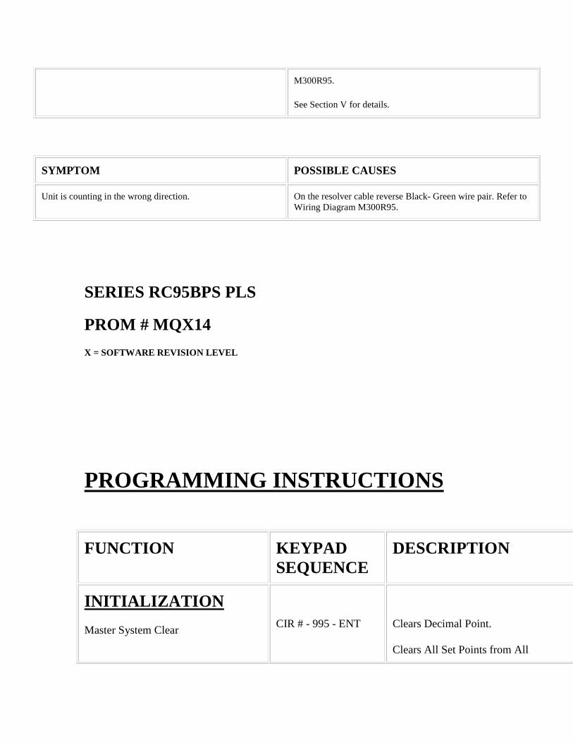
Unit is counting in the wrong direction. On the resolver cable reverse Black- Green wire pair. Refer to Wiring Diagram M300R95.
SERIES RC95BPS PLS
PROM # MQX14
X = SOFTWARE REVISION LEVEL
PROGRAMMING INSTRUCTIONS
FUNCTION KEYPAD SEQUENCE
DESCRIPTION
INITIALIZATION
Master System Clear
CIR # - 995 - ENT
Clears Decimal Point.
Clears All Set Points from All
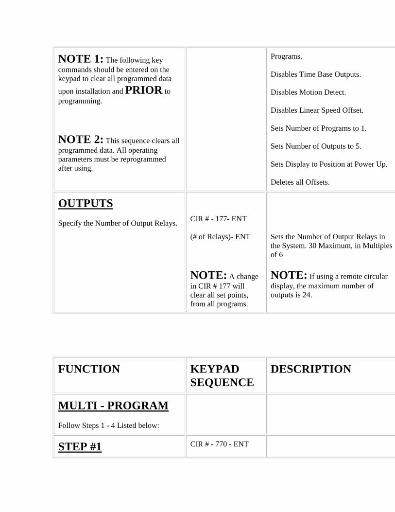
NOTE 1: The following key commands should be entered on the keypad to clear all programmed data
upon installation and PRIOR to programming.
NOTE 2: This sequence clears all programmed data. All operating parameters must be reprogrammed after using.
Programs.
Disables Time Base Outputs.
Disables Motion Detect.
Disables Linear Speed Offset.
Sets Number of Programs to 1.
Sets Number of Outputs to 5.
Sets Display to Position at Power Up.
Deletes all Offsets.
OUTPUTS
Specify the Number of Output Relays.
CIR # - 177- ENT
(# of Relays)- ENT
NOTE: A change in CIR # 177 will clear all set points, from all programs.
Sets the Number of Output Relays in the System. 30 Maximum, in Multiples of 6
NOTE: If using a remote circular display, the maximum number of outputs is 24.
FUNCTION KEYPAD SEQUENCE
DESCRIPTION
MULTI - PROGRAM
Follow Steps 1 - 4 Listed below:
STEP #1 CIR # - 770 - ENT

Specify the number of programs desired.
CIR ON - (# of Programs) - ENT
Sets the Number of Programs.
STEP #2
Inquire Amount of Set Points Available Per Program
CIR # - 770 - ENT
CIR OFF
Unit will Display the Amount of Set Points Available Per Program. No Values May Be Entered.
STEP #3
Select Program of Multi-program Option for Programming or Operation.
NOTE: Program 0 if the First Program. If 10 Programs were Previously Selected using Code 770, They will be Programs
0 - 9.
CIR # - 771 - ENT
(0 through Highest Program No.) - ENT
Display Shows Current Program in Operation.
Selects New Program for Programming or Operation. The Highest Available Program was Specified Earlier using Code 770.
STEP #4
Remaining Availability of Set Points.
CIR # - 772 - ENT Display Shows the Total Number of Set Points Available for Use in the Currently Selected Active Program. No Values may be Entered.
FUNCTION KEYPAD SEQUENCE
DESCRIPTION
SET POINTS
PROGRAMMING NEW SET POINTS
NOTE 1:

Multiple ON and OFF Set Points can be Programmed on Each Circuit. All Decimal Points Flash when More that One Set Point Exists on Selected Circuit.
NOTE 2:
An ON Set Point without Corresponding OFF Set Point results in an Output that Turns ON at Programmed Setting and Turns OFF at Zero. An OFF Set Point without Corresponding ON Set Point Results in a Circuit that Turns ON at Zero and Turns OFF at Programmed Setting.
CIR # - (1 through 30) - ENT
CIR ON - (Desired Position) - ENT
CIR OFF - (Desired Position) - ENT
-OR-
CIR OFF - (Desired Time Interval) - ENT
Selects a Limit Switch Circuit for Programming. The Circuit Number Selected CANNOT Exceed the Number of Output Relays Specified Earlier Using Code 177.
Specifies Relay Turn ON Point.
Specifies Relay Turn OFF Point.
Set Interval of the ON Time for Relays Selected Earlier for Time Based Operation Using Code 301 through 305. Display will Show a Decimal Point after Pressing the CIR OFF Key to Indicate that You are Programming in Seconds to .01 seconds.
NOTE 3: An LS may not have the same value for both the ON point and the OFF point. If a value is entered that is already a set point for that LS, only the new one will be used. For Example: If LS1 had an ON point at 100 and an OFF point of 100 was entered, the ON point at 100 would be deleted. The OFF point at 100 would then be entered. Assuming that these were the only set points, the output would turn ON at 0 and OFF at 100.
CLEAR AN EXISTING SET POINT
NOTE: This Keypad Sequence must be completed once to clear the ON set Point and a second time to clear the OFF set point. SEE NOTE 2 under Program
1) CIR # - (Output Circuit to be Cleared) - ENT
2) Press CIR ON or CIR OFF Key until Set Point to be Cleared is on Display.
Upon Pressing the CLR SET Key, the Set Point on the Display after Step 2 is Deleted.
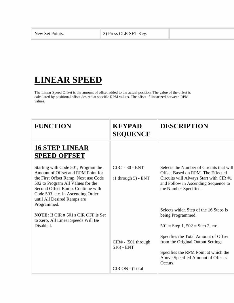
New Set Points. 3) Press CLR SET Key.
LINEAR SPEED The Linear Speed Offset is the amount of offset added to the actual position. The value of the offset is calculated by positional offset desired at specific RPM values. The offset if linearized between RPM values.
FUNCTION KEYPAD SEQUENCE
DESCRIPTION
16 STEP LINEAR SPEED OFFSET
Starting with Code 501, Program the Amount of Offset and RPM Point for the First Offset Ramp. Next use Code 502 to Program All Values for the Second Offset Ramp. Continue with Code 503, etc. in Ascending Order until All Desired Ramps are Programmed.
NOTE: If CIR # 501's CIR OFF is Set to Zero, All Linear Speeds Will Be Disabled.
CIR# - 80 - ENT
(1 through 5) - ENT
CIR# - (501 through 516) - ENT
CIR ON - (Total
Selects the Number of Circuits that will Offset Based on RPM. The Effected Circuits will Always Start with CIR #1 and Follow in Ascending Sequence to the Number Specified.
Selects which Step of the 16 Steps is being Programmed.
501 = Step 1, 502 = Step 2, etc.
Specifies the Total Amount of Offset from the Original Output Settings
Specifies the RPM Point at which the Above Specified Amount of Offsets Occurs.
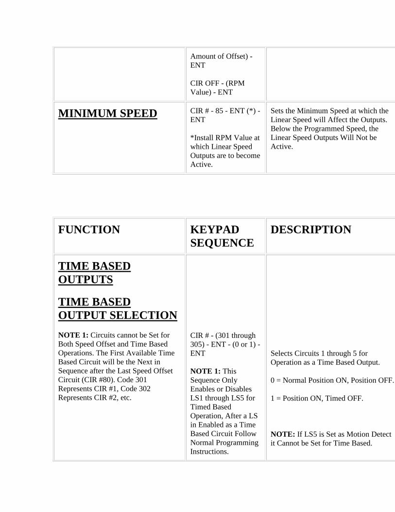
Amount of Offset) - ENT
CIR OFF - (RPM Value) - ENT
MINIMUM SPEED CIR # - 85 - ENT (*) - ENT
*Install RPM Value at which Linear Speed Outputs are to become Active.
Sets the Minimum Speed at which the Linear Speed will Affect the Outputs. Below the Programmed Speed, the Linear Speed Outputs Will Not be Active.
FUNCTION KEYPAD SEQUENCE
DESCRIPTION
TIME BASED OUTPUTS
TIME BASED OUTPUT SELECTION
NOTE 1: Circuits cannot be Set for Both Speed Offset and Time Based Operations. The First Available Time Based Circuit will be the Next in Sequence after the Last Speed Offset Circuit (CIR #80). Code 301 Represents CIR #1, Code 302 Represents CIR #2, etc.
CIR # - (301 through 305) - ENT - (0 or 1) - ENT
NOTE 1: This Sequence Only Enables or Disables LS1 through LS5 for Timed Based Operation, After a LS in Enabled as a Time Based Circuit Follow Normal Programming Instructions.
Selects Circuits 1 through 5 for Operation as a Time Based Output.
0 = Normal Position ON, Position OFF.
1 = Position ON, Timed OFF.
NOTE: If LS5 is Set as Motion Detect it Cannot be Set for Time Based.
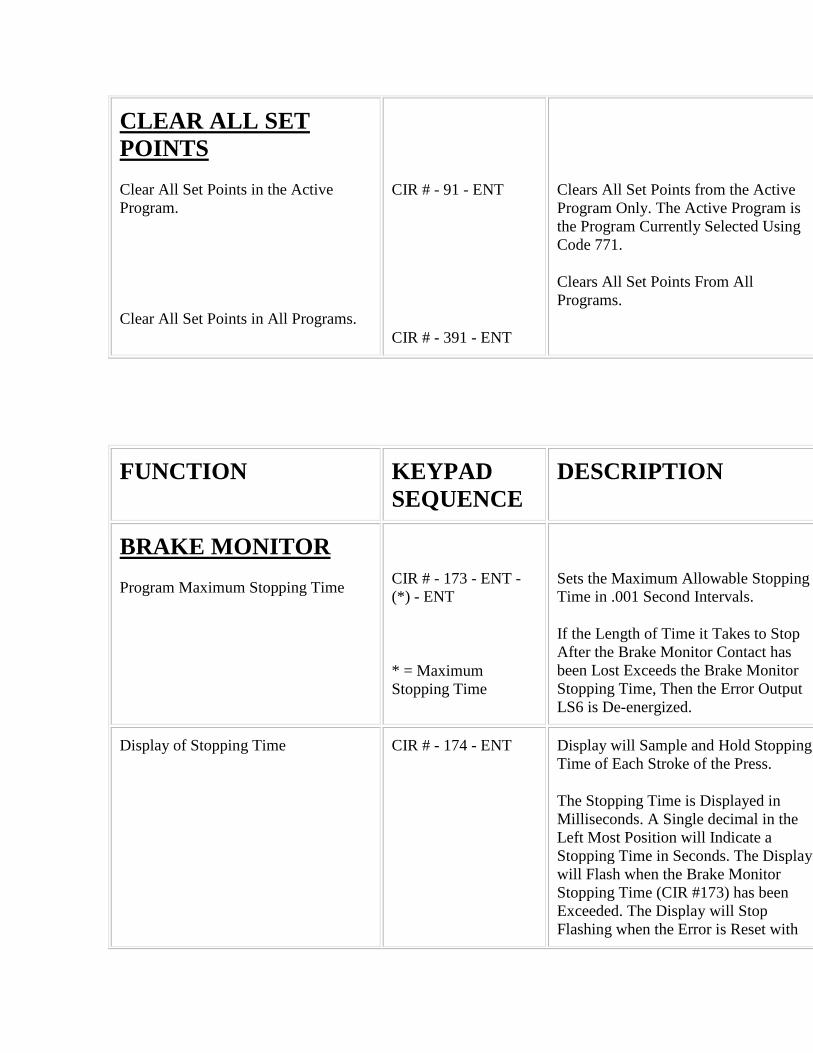
CLEAR ALL SET POINTS
Clear All Set Points in the Active Program.
Clear All Set Points in All Programs.
CIR # - 91 - ENT
CIR # - 391 - ENT
Clears All Set Points from the Active Program Only. The Active Program is the Program Currently Selected Using Code 771.
Clears All Set Points From All Programs.
FUNCTION KEYPAD SEQUENCE
DESCRIPTION
BRAKE MONITOR
Program Maximum Stopping Time
CIR # - 173 - ENT - (*) - ENT
* = Maximum Stopping Time
Sets the Maximum Allowable Stopping Time in .001 Second Intervals.
If the Length of Time it Takes to Stop After the Brake Monitor Contact has been Lost Exceeds the Brake Monitor Stopping Time, Then the Error Output LS6 is De-energized.
Display of Stopping Time CIR # - 174 - ENT Display will Sample and Hold Stopping Time of Each Stroke of the Press.
The Stopping Time is Displayed in Milliseconds. A Single decimal in the Left Most Position will Indicate a Stopping Time in Seconds. The Display will Flash when the Brake Monitor Stopping Time (CIR #173) has been Exceeded. The Display will Stop Flashing when the Error is Reset with
the Fault Check Input. Exiting this Mode is Done Only by Pressing the RPM/POS Key. No Values may be Entered.
Display of Stopping Angle CIR # - 175 - ENT Display will Sample and Hold the Number of Degrees Traveled after Initiation of Brake Command.
The Stopping Distance is the Distance Traveled since the Loss of the Contact. The Display will Flash when the Brake Monitor Stopping Time (CIR #173) has been
Exceeded. The Display will Stop Flashing when the Error is Reset with the Fault Check Input. Exiting this Mode is Done Only by Pressing the RPM/POS Key. No Values May be Entered.
FUNCTION KEYPAD SEQUENCE
DESCRIPTION
OFFSET
Offset to Synchronize with Machine Position.
Step 1: Stop Machine at Known Location.
NOTE: If Pressing of the Offset Button Displays EEE, See page 16 for Further Instructions.
OFS - (Actual Machine Position) - ENT
Display Changes to Position Entered. Display and Outputs are Now Synchronized with Actual Machine Position.
MOTION DETECT
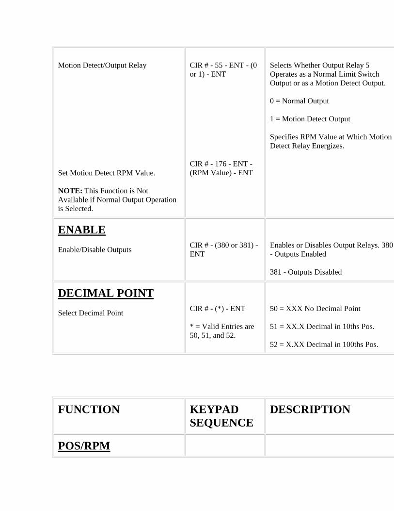
Motion Detect/Output Relay
Set Motion Detect RPM Value.
NOTE: This Function is Not Available if Normal Output Operation is Selected.
CIR # - 55 - ENT - (0 or 1) - ENT
CIR # - 176 - ENT -(RPM Value) - ENT
Selects Whether Output Relay 5 Operates as a Normal Limit Switch Output or as a Motion Detect Output.
0 = Normal Output
1 = Motion Detect Output
Specifies RPM Value at Which Motion Detect Relay Energizes.
ENABLE
Enable/Disable Outputs
CIR # - (380 or 381) - ENT
Enables or Disables Output Relays. 380 - Outputs Enabled
381 - Outputs Disabled
DECIMAL POINT
Select Decimal Point
CIR # - (*) - ENT
* = Valid Entries are 50, 51, and 52.
50 = XXX No Decimal Point
51 = XX.X Decimal in 10ths Pos.
52 = X.XX Decimal in 100ths Pos.
FUNCTION KEYPAD SEQUENCE
DESCRIPTION
POS/RPM
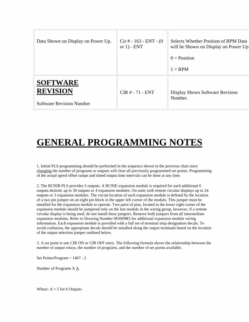
Data Shown on Display on Power Up. Cir # - 163 - ENT - (0 or 1) - ENT
Selects Whether Position of RPM Data will be Shown on Display on Power Up.
0 = Position
1 = RPM
SOFTWARE REVISION
Software Revision Number
CIR # - 71 - ENT
Display Shows Software Revision Number.
GENERAL PROGRAMMING NOTES
1. Initial PLS programming should be performed in the sequence shown in the previous chart since changing the number of programs or outputs will clear all previously programmed set points. Programming of the actual speed offset ramps and timed output time intervals can be done at any time.
2. The RC95B PLS provides 5 outputs. A RC95E expansion module is required for each additional 6 outputs desired, up to 30 outputs or 4 expansion modules. On units with remote circular displays up to 24 outputs or 3 expansion modules. The circuit location of each expansion module is defined by the location of a two pin jumper on an eight pin block in the upper left corner of the module. This jumper must be installed for the expansion module to operate. Two pairs of pins, located in the lower right corner of the expansion module should be jumpered only on the last module in the wiring group, however, if a remote circular display is being used, do not install these jumpers. Remove both jumpers from all intermediate expansion modules. Refer to Drawing Number M3009R5 for additional expansion module wiring information. Each expansion module is provided with a full set of terminal strip designation decals. To avoid confusion, the appropriate decals should be installed along the output terminals based on the location of the output selection jumper outlined below.
3. A set point is one CIR ON or CIR OFF entry. The following formula shows the relationship between the number of output relays, the number of programs, and the number of set points available.
Set Points/Program = 1467 - 2
Number of Programs X A
Where: A = 5 for 6 Outputs

6 for 12 Outputs
7 for 18 Outputs
8 for 24 Outputs
9 for 30 Outputs
Set Points are in whole numbers ( Drop Decimal).
Example: 12 Output Relays with 10 Programs
S.P. = 1467 - 2 = 24.45 - 2 = 22 Set Points/Program
10 * 6
The following table shows the relationship between the number of outputs, the number of programs, and the number of set points per program. The table only shows a few of the many combinations that are possible. Before programming outputs, it is advisable to verify that enough set points are available, otherwise, the number of programs may need to be reduced. A set point is one CIR ON or CIR OFF entry.
6 OUTPUTS 12 OUTPUTS 18 OUTPUTS 24 OUTPUTS 30 OUTPUTS
1/253 1/242 1/207 1/181 1/161
20/12 9/25 5/39 4/43 2/79
26/9 12/18 8/24 5/34 3/52
36/6 17/12 10/18 7/24 5/30
97/1 27/7 13/14 8/20 6/25
Number of Resulting Number of Set Points Per Program
Programs Selected
4. A position based output may have multiple CIR ON and CIR OFF set points. Flashing decimal points will indicate that more than one set point has been programmed on the circuit being displayed.
5. A time based output may only have one CIR ON and CIR OFF set point. This upon the CIR OFF time data which is displayed and programmed in 0.001 second increments. A time based output uses up three set points in the calculations covered under General Programming Note 3.
6. To change a CIR ON set point for a time based circuit, it must first be cleared, and then the new set point can be entered.
7. Outputs 1 through 5 may incorporate linear speed offset or may be time based. However, no output can be both. In addition, LS5 may be selected to be a motion detect output. If two or three types of outputs are required, first select the number of linear speed circuits required (CIR 80) and then individually select the time based outputs and motion detect output.

EXAMPLE: Outputs 1 & 2 Linear Speed
CIR # - 80 - ENT - 2 - ENT
Outputs 3 & 4 Time Based
CIR # - 303 - ENT - 1 - ENT
CIR # - 304 - ENT - 1 - ENT
Output 5 Motion Detect
CIR # - 55 - ENT - 1 - ENT
8. The scale factor for this software package is preset to 360 and cannot be changed.
BRAKE MONITOR OPERATIONAL DESCRIPTION
The RC95B Brake Monitor PLS offers an on-line monitor which checks the stopping time of the press against a customer selected preset stopping time in milliseconds, and can be used to check the stopping distance at any point during the stroke.
With keypad commands, the digital readout will display the stopping time (CIR# 174) or the stopping distance (degrees) (CIR# 175) of each cycle. If the time from de-energization of the press clutch voltage to stopping the ram exceeds a customer's programmed value, the brake monitor output relay will de-energize which can be used to stop further press operation. This output can be rest by momentarily opening and the closing the fault check system but both use the fault check input to reset their individual faults. Opening the fault check input will de-energize the fault and brake monitor output relays allowing the user to verify that these outputs are operating properly and have not been hard wired.
NOTE: In efforts to make the brake monitor fail safe we have changed the brake monitor circuit so that if you see motion without seeing the brake input, a brake fault will occur.

WIRING
Wire programmer per Drawing M3009R5. In this drawing, relay LS6 is the brake monitor relay. It is normally energized (N.O. contact is closed and N.C. contact is open) and de-energized on a fault condition. Operating in this manner a disconnected wire or disconnected relay will indicate a fault condition.
Relay LS5 is either a standard LS output or the motion detect output, as selected by the customer. If operating as a motion detect output, the relay will energize when the transducer speed is greater that the customer programmed RPM value.
The brake monitor calculates stopping time by monitoring the time span between seeing the clutch disengage and the press coming to a complete stop. The system begins this timing sequence when it sees the isolated contact, wired between input terminals 14 and 15, open. This isolated contact can be the contact of an existing relay in your control circuit or it can be provided by General Purpose Relay with DPDT contacts rated at 10 Amps with 120V 50/60 Hz. Coil as shown on the next page. The contact of the brake monitor input relay must open when the clutch disengages and all wiring between its isolated contact
and terminals 14 and 15 of the RC95 programmer must be protected from induced electrical noise.
PROGRAMMING AND MONITORING
To monitor press stopping time, press CIR# - 174 - ENT. Stopping time will be displayed in milliseconds from 001 to 999. Three decimal points indicates a stopping time in milliseconds, a single decimal point, two places to the left, will indicate a stopping time in seconds to one hundredth of second. If the customer's preset stopping time is exceeded, the display and decimal(s) will flash. They will continue to flash until the brake monitor output has been reset.
To monitor press stopping angle, press CIR# - 175 - ENT. Stopping distance will be displayed in degree increments. If the stopping time is exceeded while in the stopping angle mode, the display will flash. It will continue to flash until the brake monitor relay has been reset.
When operating in either of the above modes, the display will maintain the stopping data until initiation of the next timing cycle. At this point, the display will indicate dashes until new data is available. Pressing of the POS or RPM keys will return the display from this operating mode.
To program the maximum acceptable stopping time, press CIR# - 173 - ENT. The time data can be programmed from 001 to 999 milliseconds. If the programmed stopping time is exceeded, the brake monitor output (L.S. #6) will de-energize until the fault check input is opened and then closed again.

LINEAR SPEED OPERATION DESCRIPTION
The sixteen step linear speed offset feature allows up to 16 different offset steps to be selected and a different amount of positive or negative (advance or retard) offset to be programmed between each of the sixteen steps.
Access Codes 501 through 516 are used to select a step for programming of the ramp between it and the previous step. Code 501 is used to access and program the ramp between 0 RPM and the RPM value assigned to the first step. Code 502 is used to access and program the ramp between the RPM value of the first step and the RPM value assigned to the second step.
After using the access code to call up a step for programming, the CIR ON key is pressed followed by the total amount of offset, from zero offset, to be applied to the circuit at the specified RPM value. The CIR OFF key is pressed next followed by the RPM value of that step. The programmed offset value will be the

total amount of offset being applied to the circuits from their zero offset starting values. This allows the circuits to be advanced or retarded between any two steps. (Refer to Page 4 for Programming Sequence.)
The above graph shows an example of four steps of linear offset in which the output circuits are being advanced in the first two steps. Retarded between the second and third steps, and remain unchanged, between the third and fourth. The first step (501) is programmed to linearly advance the selected outputs by 20 degrees between 0 and 60 RPM. Circuits originally programmed to turn on at 150 degrees will be turning on a 130 degrees while at 60 RPM. The second step (502) is programmed to advance these some outputs to a total of 50 degrees as RPM rises between 60 and 100 RPM. The example circuit mentioned above, that was originally programmed to turn on at 150 degrees, will now be turning on at 100 degrees while at 100 RPM. The third step (503) is programming to retard the circuits back to a total of 30 degrees as RPM continues to rise from 100 to 140 RPM. The example circuit, originally programmed to turn on at 150 degrees is now turning on at 120 degrees while running at 140 RPM. The fourth step (504) is programmed to maintain a fixed 30 degrees of total offset between 140 and 200 RPM.
The offset (advance or retard) is applied linearly between each step and the offset follows the same curve as RPM decreases.
RC95BPS - MQX14 BRAKE MONITOR, TIMED BASED
16 STEP LINEAR SPEED OFFSET, MULTI-PROGRAM
CIRCULAR REMOTE DISPLAY
SUMMARY OF FUNCTIONS:
#50 Clears Decimal Points (123).
#51 Sets decimal point to tenths (12.3).
#52 Sets decimal point to hundredths (1.23).
#55 Selects LS #5 as motion detect or regular output.
#71 Displays software revision number.
#80 Number of linear speed circuits.
#85 Minimum speed for linear speed offset.
#91 Clear all set points from active program.
#163 Sets display at power-up for position or RPM.

#173 Sets maximum brake stopping time.
#174 Displays last brake stopping time.
#175 Displays last brake stopping distance.
#176 Sets motion detect threshold.
#177 Displays number of outputs.
#301 Displays and set output type (time based or regular) for CIR #1.
#302 Displays and set output type (time based or regular) for CIR #2.
#303 Displays and set output type (time based or regular) for CIR #3.
#304 Displays and set output type (time based or regular) for CIR #4.
#305 Displays and set output type (time based or regular) for CIR #5.
#380 Enable outputs.
#381 Disable outputs.
#391 Clear all set points from all programs.
#501-516 - CIR ON Positional offset for linear speed offset.
#501-516 - CIR OFF RPM value for linear speed offset.
#770 - CIR ON Sets maximum number of programs.
#770 - CIR OFF Displays number of set points per program.
#771 Sets active program.
#772 Displays number of set points still available in active program.
#995 Resets all data to initial values.
UPDATE TIMES: The update time varies depending on the number of outputs enabled and whether any circuits are time based or linear speed. Times for each combination follows:
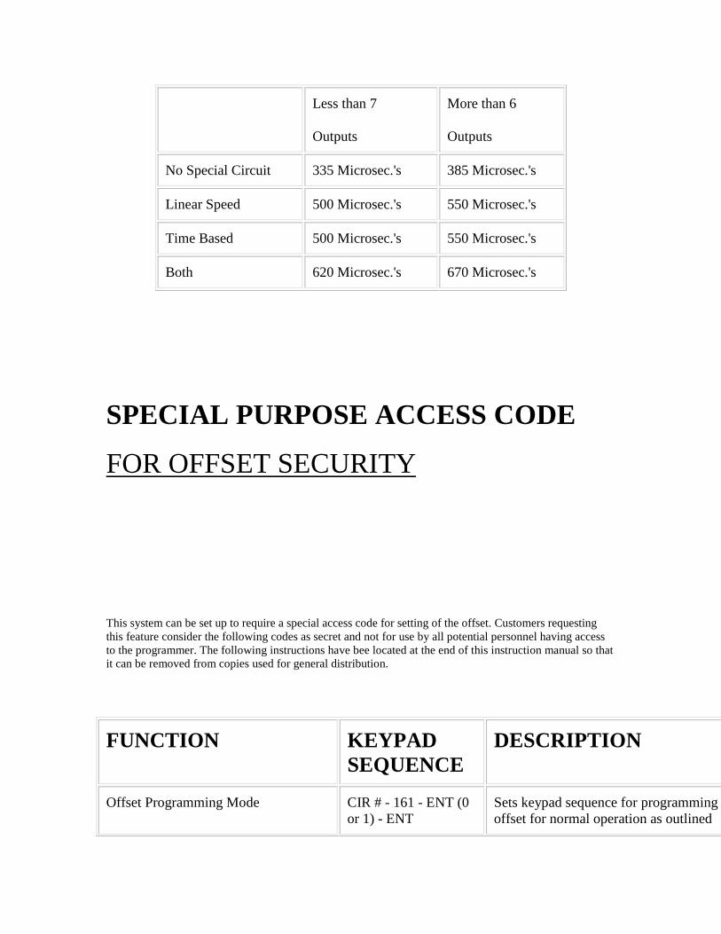
Less than 7
Outputs
More than 6
Outputs
No Special Circuit 335 Microsec.'s 385 Microsec.'s
Linear Speed 500 Microsec.'s 550 Microsec.'s
Time Based 500 Microsec.'s 550 Microsec.'s
Both 620 Microsec.'s 670 Microsec.'s
SPECIAL PURPOSE ACCESS CODE
FOR OFFSET SECURITY
This system can be set up to require a special access code for setting of the offset. Customers requesting this feature consider the following codes as secret and not for use by all potential personnel having access to the programmer. The following instructions have bee located at the end of this instruction manual so that it can be removed from copies used for general distribution.
FUNCTION KEYPAD SEQUENCE
DESCRIPTION
Offset Programming Mode CIR # - 161 - ENT (0 or 1) - ENT
Sets keypad sequence for programming offset for normal operation as outlined

earlier in these instructions or for special access code.
0 = Normal Operation via Offset Key.
1 = Special Access Code 162
Programming Offset Using Special Access Code
Step 1 - Stop Machine at Known Location.
CIR # - 162 - ENT - (Actual Machine Position) - ENT
Display Changes to Position Entered. Display and Outputs are now Synchronized with Actual Machine Position.