time sensitive ethernet
TRANSCRIPT

Call: +44 345 222 1711 / +353 1 210 1711 Email: [email protected] Visit: bsigroup.com
Time Sensitive EthernetThe future for industrial
control system networks
A Whitepaper

2 Time Sensitive Ethernet - The Future for ICS Networks Call: +44 345 222 1711 / +353 1 210 1711 Email: [email protected] Visit: bsigroup.com
Introduction
Local Area Networks (LAN) are extremely important in the fully interconnected
world we live in nowadays, acting as the backbone that enable the interaction
between IT elements. They are also used to link local IT systems with the Wide
Area Network (Internet).
In the industrial world, LANs are even more critical, fulfilling real-time
communication requirements to the interaction of the different elements present
in SCADA (Supervisory Control and Data Acquisition).
This paper will focus on the new enhancements of the most widespread LAN:
ETHERNET, and how they allow the standard to achieve a prominent position in
the industrial world.
Local Area Networks (LANs), OT Architecture Review
1 Ethernet definition provided by Cisco. http://www.cisco.com/c/en/us/td/docs/net_mgmt/active_network_abstraction/3-7/reference/guide/ANARef-Guide37/ethrnt.html
Ethernet LANs
Ethernet is, by far, the most used Local Area Network used
in IT systems all over the world. It is an open, manufacturer
independent technology, driven by the Standard IEEE 802.3
(part of the ISO standard organization) that has found wide
acceptance by network hardware manufacturers.
“Ethernet refers to the family of LAN products covered by the IEEE
802.3 standard that defines the carrier sense multiple access
collision detect (CSMA/CD) protocol. Four data rates are currently
defined for operation over optical fiber and twisted-pair cables:
10Base-T Ethernet (10 Mb/s), Fast Ethernet (100 Mb/s), Gigabit
Ethernet (1000 Mb/s) and 10-Gigabit Ethernet (10 GB/s”).1
The Ethernet standard is mature, and has high speed
capabilities. However, the CSMA/CD nature of Ethernet does
not support time-deterministic operation. In other words,
communications are potentially very fast but the maximum
time for a message transmission is not guaranteed a priority.
IT and OT
Before introducing the Automation Pyramid in section 1.3,
this section provides a brief comparison for the IT and OT
concepts.
The world of traditional Information Technology (IT)
has split over the years into several categories. In the
case of Information Technology applied to supporting
manufacturing processes and control systems the
differences from traditional IT is such that a new category
has been defined; the OT ( Operational Technology) category.
The key concepts and differences between IT and OT are
illustrated in the table on the following page.
3Time Sensitive Ethernet - The Future of ICS NetworksCall: +44 345 222 1711 / +353 1 210 1711 Email: [email protected] Visit: bsigroup.com
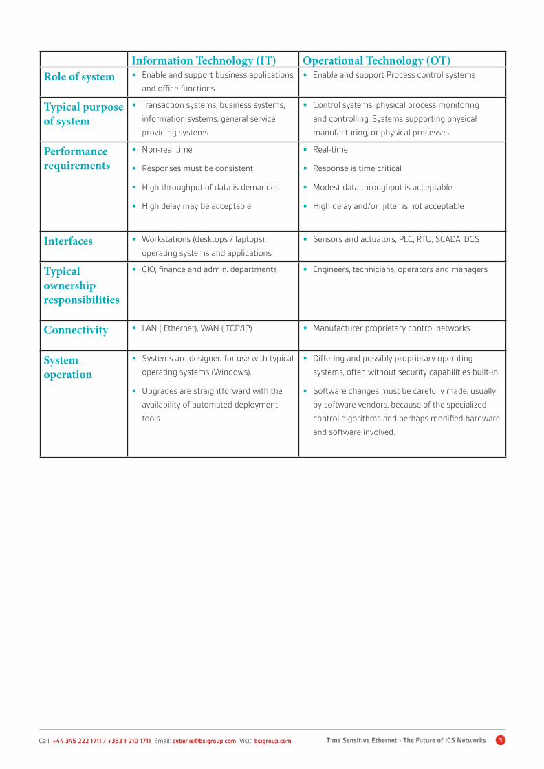
Information Technology (IT) Operational Technology (OT)Role of system • Enable and support business applications
and office functions
• Enable and support Process control systems
Typical purpose of system
• Transaction systems, business systems,
information systems, general service
providing systems
• Control systems, physical process monitoring
and controlling. Systems supporting physical
manufacturing, or physical processes.
Performance requirements
• Non-real time
• Responses must be consistent
• High throughput of data is demanded
• High delay may be acceptable
• Real-time
• Response is time critical
• Modest data throughput is acceptable
• High delay and/or jitter is not acceptable
Interfaces • Workstations (desktops / laptops),
operating systems and applications
• Sensors and actuators, PLC, RTU, SCADA, DCS
Typicalownership responsibilities
• CIO, finance and admin. departments • Engineers, technicians, operators and managers
Connectivity • LAN ( Ethernet), WAN ( TCP/IP) • Manufacturer proprietary control networks
System operation
• Systems are designed for use with typical
operating systems (Windows).
• Upgrades are straightforward with the
availability of automated deployment
tools
• Differing and possibly proprietary operating
systems, often without security capabilities built-in.
• Software changes must be carefully made, usually
by software vendors, because of the specialized
control algorithms and perhaps modified hardware
and software involved.
4 Time Sensitive Ethernet - The Future for ICS Networks Call: +44 345 222 1711 / +353 1 210 1711 Email: [email protected] Visit: bsigroup.com
Automation Pyramid
OT systems follow an architecture that is traditionally
represented with the Automation Pyramid.
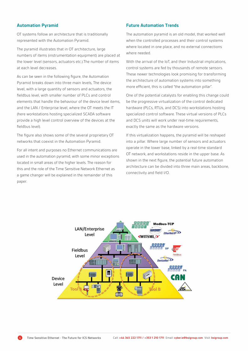
The pyramid illustrates that in OT architecture, large
numbers of items (instrumentation equipment) are placed at
the lower level (sensors, actuators etc.).The number of items
at each level decreases.
As can be seen in the following figure, the Automation
Pyramid breaks down into three main levels, The device
level, with a large quantity of sensors and actuators, the
fieldbus level, with smaller number of PLCs and control
elements that handle the behaviour of the device level items,
and the LAN / Enterprise level, where the OT meets the IT
(here workstations hosting specialized SCADA software
provide a high level control overview of the devices at the
fieldbus level).
The figure also shows some of the several proprietary OT
networks that coexist in the Automation Pyramid.
For all intent and purposes no Ethernet communications are
used in the automation pyramid, with some minor exceptions
located in small areas of the higher levels. The reason for
this and the role of the Time Sensitive Network Ethernet as
a game changer will be explained in the remainder of this
paper.
Future Automation Trends
The automation pyramid is an old model, that worked well
when the controlled processes and their control systems
where located in one place, and no external connections
where needed.
With the arrival of the IoT, and their Industrial implications,
control systems are fed by thousands of remote sensors.
These newer technologies look promising for transforming
the architecture of automation systems into something
more efficient, this is called “the automation pillar”.
One of the potential catalysts for enabling this change could
be the progressive virtualization of the control dedicated
hardware (PLCs, RTUs, and DCS) into workstations hosting
specialized control software. These virtual versions of PLCs
and DCS units will work under real-time requirements,
exactly the same as the hardware versions.
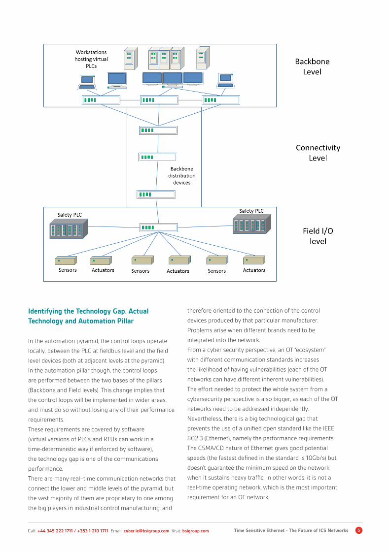
If this virtualization happens, the pyramid will be reshaped
into a pillar. Where large number of sensors and actuators
operate in the lower base, linked by a real-time standard
OT network, and workstations reside in the upper base. As
shown in the next figure, the potential future automation
architecture can be divided into three main areas, backbone,
connectivity and field I/O.
5Time Sensitive Ethernet - The Future of ICS NetworksCall: +44 345 222 1711 / +353 1 210 1711 Email: [email protected] Visit: bsigroup.com
Identifying the Technology Gap. Actual Technology and Automation Pillar In the automation pyramid, the control loops operate
locally, between the PLC at fieldbus level and the field
level devices (both at adjacent levels at the pyramid).
In the automation pillar though, the control loops
are performed between the two bases of the pillars
(Backbone and Field levels). This change implies that
the control loops will be implemented in wider areas,
and must do so without losing any of their performance
requirements.
These requirements are covered by software
(virtual versions of PLCs and RTUs can work in a
time-deterministic way if enforced by software),
the technology gap is one of the communications
performance.
There are many real–time communication networks that
connect the lower and middle levels of the pyramid, but
the vast majority of them are proprietary to one among
the big players in industrial control manufacturing, and
therefore oriented to the connection of the control
devices produced by that particular manufacturer.
Problems arise when different brands need to be
integrated into the network.
From a cyber security perspective, an OT “ecosystem”
with different communication standards increases
the likelihood of having vulnerabilities (each of the OT
networks can have different inherent vulnerabilities).
The effort needed to protect the whole system from a
cybersecurity perspective is also bigger, as each of the OT
networks need to be addressed independently.
Nevertheless, there is a big technological gap that
prevents the use of a unified open standard like the IEEE
802.3 (Ethernet), namely the performance requirements.
The CSMA/CD nature of Ethernet gives good potential
speeds (the fastest defined in the standard is 10Gb/s) but
doesn’t guarantee the minimum speed on the network
when it sustains heavy traffic. In other words, it is not a
real-time operating network, which is the most important
requirement for an OT network.

6 Time Sensitive Ethernet - The Future for ICS Networks Call: +44 345 222 1711 / +353 1 210 1711 Email: [email protected] Visit: bsigroup.com
Limitations of Classic Ethernet Ethernet types covered by the IEEE 802.3 Standard
There are many Ethernet types covered by the IEE 802.3 Standards. The following table will depict the most representative
categories, with the maximum speed, cable length and cable type of each:
Name IEEE Standard Max. Speed Cable Type Maximum Length
Ethernet (Obso-lete)
• 802.3 • 10 Mb/s • Cat 3 UTP
(Unshielded Twisted
Pair)
• 100m
Fast Ether-net/100Base-T
• 802.3u • 100Mb/s • Cat 5 UTP / STP
(Shielded Twisted
Pair)
• 2000m
Gigabit Ethernet/GigE
• 802.3z • 1000Mb/s • Cat 5 UTP / 50
Micron FO (Fibre
Optic Cable)
• 100m-500m
10 Gigabit Ether-net
• 802.eae • 10Gb/s • Cat 7 UTP / SMFO
(Single Mode fibre
Optic)
• 300 - 40,000m
CSMA/CD and its capability to act as an arbitrator for devices in the Ethernet LAN
The Carrier Sense Multiple Access / Collision Detect, is
the media access control used by the “classic” Ethernet .
The main reason for the existence of the CSMA/CD is the
collision. Collisions take place when two or more devices try
to transmit data at the same time in the same transmission
media. The CSMA/CD provides procedures to handle
transmissions considering data collisions as a factor.
Carrier Sense
The Carrier Sense is the ability of the Network Interface Card
(NIC) to check the network for any on-going communication.
The NIC will only allow a new communication to start if there
are no on-going communications. Nevertheless, a collision
can occur if there are multiple devices willing to transmit at
the same time.
Multiple Access
The Multiple Access functionality handles the existence of
multiple devices using the same network. It basically raises a
flag when the occurrence of collisions is a possibility.
1 Stan Schneider, President of Real-Time Innovation white paper “Making Ethernet work in real time” https://eclass.upatras.gr/mod-ules/document/file.php/EE653/%CE%A3%CE%B7%CE%BC%CE%B5%CE%B9%CF%8E%CF%83%CE%B5%CE%B9%CF%82%20-%20%CE%A7%CF%81%CE%AE%CF%83%CE%B9%CE%BC%CE%B1/Making%2BEthernet%2BWork%2Bin%2BReal-Time.pdf
Collision Detect
The collision detect scopes the detection of collisions, and
how these events are handled as well. When a collision
is detected, the NIC sends a jamming signal to all the
devices in the network, making them aware of the incident.
After that, a back-off algorithm tells all the devices to
wait a random amount of time before trying to start new
communications. (The random delay in communications is
introduced to minimize the possibility of another collision).
Non Pre-Deterministic Behaviour
The very nature of the CSMA/CD makes it impossible to
assure real time operations. As the number of collisions
produced in the network cannot be known a priori, the
maximum time to successfully transmit a message is not
predetermined. Statistical studies state that the operation
in a LAN with CSMA/CD could be considered in real-time
with a traffic load less than 20% of the total capacity 1. (That,
however is merely an estimate).

7Time Sensitive Ethernet - The Future of ICS NetworksCall: +44 345 222 1711 / +353 1 210 1711 Email: [email protected] Visit: bsigroup.com
Year reliability probability for 1.5 ms delay requirement
Industrial Control Network Requirements
Time Synchronization
Time synchronization is a key requirement for any
network designed to work in real-time. Each of the
actors present in the network must share the same time
basis, with the highest possible precision, to be able to
measure the transmission events consistently.
Packet Loss Ratio
The packet loss ratio expresses the probability for one
packet transmitted in a network segment to be lost
(a packet loss ratio of 0.5 means that there is a 50%
probability for any packet to be lost).
Let’s consider a hypothetical automotive production
plant with 1000 network segments, each of them
sending an average quantity of 10,000 packets per
second. This means that in one day (24 hours) 1,012
packets will be sent. If we have a packet loss ratio of 10-6
(which seems really good at first sight) the probability of
having two consecutive lost packets is 10-12.
Assuming that a production machine will fail safe after
having two consecutive packet losses, we can estimate
one production fault per day, with a packet loss ratio
of 10-6, normally this is not acceptable in automotive
performance requirements.
Usually industrial production systems are designed
to optimise output capacity. In other words, it is
common for a production system to be built to work
uninterrupted, for example.
In the automotive industry, production only stops once or
twice a year for necessary periodic maintenance.
Therefore, “unscheduled stops” are a big concern for
industrial manufacturing, which makes the packet loss
ratio a critical metric for industrial control network
performance.

8 Time Sensitive Ethernet - The Future for ICS Networks Call: +44 345 222 1711 / +353 1 210 1711 Email: [email protected] Visit: bsigroup.com
Critical Stream Assurance
There are different priority levels in an industrial control
network. If they are all time-sensitive, then a delay or
packet loss in a control signal that produces a fault (and
stops the production provoking “only” economic impact)
should have a lower priority than a critical alarm which
could lead to a potential loss of human lives (if ignored).
Transmission for the “critical priority” stream must be
assured, even if that means that lower priority streams
are delayed.
Different Priority Streams Convergence
The assurance of critical priority transmission does not
mean that the lower priorities are not time sensitive.
There must be a convergence when scoping all the
priority range. This means that control networks need
to have “space” in their bandwidth for all the packets,
independent of their priority. To make this possible,
the load of each priority has to be limited in a control
network. (If 100% of critical priority load is allowed in
a network, only these communications will arrive).The
bandwidth of the network itself must be adjusted in the
design phase, taking in account the estimated load for
each of the priorities.
Closing the Gap: TSN Ethernet Features
This section describes the new features of the time-sensitive Ethernet
under development in the IEEE 802.3 series, effectively closing the gap that
prevented Ethernet from acting as a standard in industrial control systems
networks.
Time Synchronization
Any network working in real-time needs the best
possible clock for driving the network “timestamp”, and
a quick and effective means to select another one when
that clock fails. In order to do this, all devices capable
of time synchronization present in the network are
designated as “masters”. Then, one of them acquires
the status of “grandmaster”, through the execution of
a selection algorithm (the Best Master Clock Algorithm
BMCA). If for any reason the “grandmaster” fails, the
system automatically switches over to one of the
potential “grandmasters” on the network that is at least
as good as any other.
Once the “grandmaster” is determined, it sends
information, including the current synchronized time to
all the time-aware systems in the network. The received
synchronized time must be corrected, adding the
propagation time for the message transmission.1
1 The Time-synchronization mechanisms present a high level of complexity. The scope of this paper is to introduce the basic rules that drive them. Refer the IEEE 802.1AS for more detailed information about grandmaster selection and Time synchronization. https://standards.ieee.org/findstds/standard/802.1AS-2011.html
Three Priority Classes
TSN schedules three types of priorities, enabling
coexistence of different traffic classes with different
requirements in the same network.
• Best Effort Traffic: The lowest priority communication
in a control network (for a real-time network)
• Soft Real-Time traffic: Control communications with
higher priority than best effort traffic, addressing
some real-time requirements
• Hard Real-Time traffic: High priority traffic for critical
control loops
9Time Sensitive Ethernet - The Future of ICS NetworksCall: +44 345 222 1711 / +353 1 210 1711 Email: [email protected] Visit: bsigroup.com
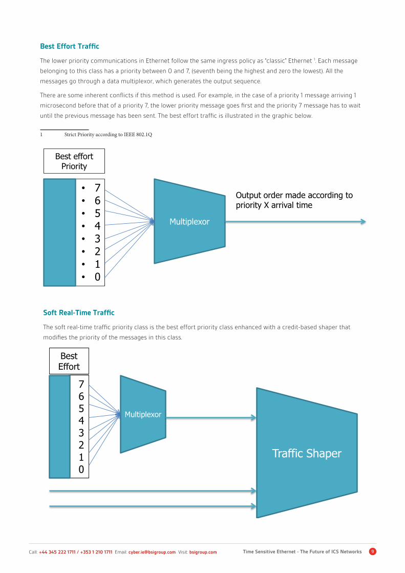
Best Effort Traffic
The lower priority communications in Ethernet follow the same ingress policy as “classic” Ethernet 1. Each message
belonging to this class has a priority between 0 and 7, (seventh being the highest and zero the lowest). All the
messages go through a data multiplexor, which generates the output sequence.
There are some inherent conflicts if this method is used. For example, in the case of a priority 1 message arriving 1
microsecond before that of a priority 7, the lower priority message goes first and the priority 7 message has to wait
until the previous message has been sent. The best effort traffic is illustrated in the graphic below.
1 Strict Priority according to IEEE 802.1Q
Soft Real-Time Traffic
The soft real-time traffic priority class is the best effort priority class enhanced with a credit-based shaper that
modifies the priority of the messages in this class.
76543210
Best Effort
Multiplexor
Traffic Shaper
• 7• 6• 5• 4• 3• 2• 1• 0
Best effort Priority
Multiplexor
Output order made according to priority X arrival time
10 Time Sensitive Ethernet - The Future for ICS Networks Call: +44 345 222 1711 / +353 1 210 1711 Email: [email protected] Visit: bsigroup.com
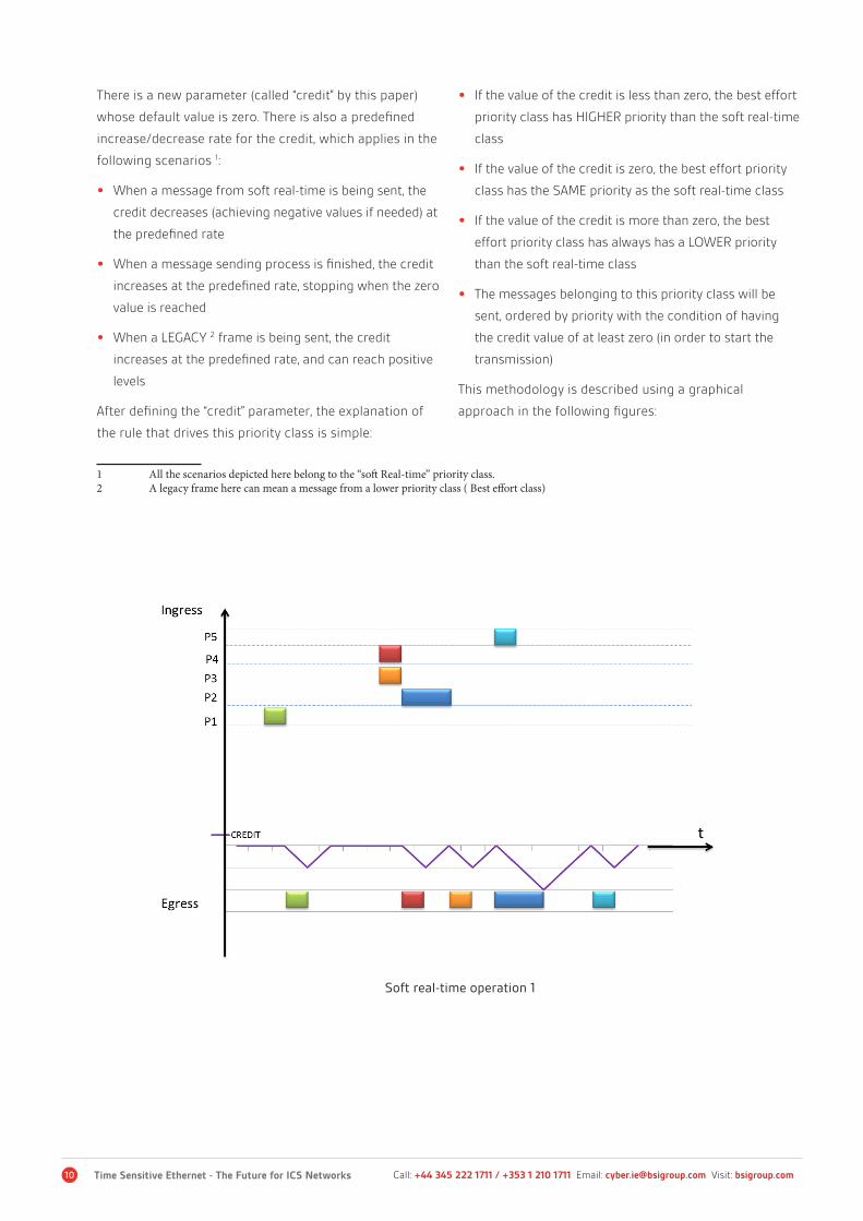
There is a new parameter (called “credit” by this paper)
whose default value is zero. There is also a predefined
increase/decrease rate for the credit, which applies in the
following scenarios 1:
• When a message from soft real-time is being sent, the
credit decreases (achieving negative values if needed) at
the predefined rate
• When a message sending process is finished, the credit
increases at the predefined rate, stopping when the zero
value is reached
• When a LEGACY 2 frame is being sent, the credit
increases at the predefined rate, and can reach positive
levels
After defining the “credit” parameter, the explanation of
the rule that drives this priority class is simple:
1 All the scenarios depicted here belong to the “soft Real-time” priority class.2 A legacy frame here can mean a message from a lower priority class ( Best effort class)
• If the value of the credit is less than zero, the best effort
priority class has HIGHER priority than the soft real-time
class
• If the value of the credit is zero, the best effort priority
class has the SAME priority as the soft real-time class
• If the value of the credit is more than zero, the best
effort priority class has always has a LOWER priority
than the soft real-time class
• The messages belonging to this priority class will be
sent, ordered by priority with the condition of having
the credit value of at least zero (in order to start the
transmission)
This methodology is described using a graphical
approach in the following figures:
Soft real-time operation 1

11Time Sensitive Ethernet - The Future of ICS NetworksCall: +44 345 222 1711 / +353 1 210 1711 Email: [email protected] Visit: bsigroup.com
The graphic represent a TSN device, applying the
traffic shaper to order the messages that arrive to it.
The ingress represents the messages that arrive to
the device and the egress the same messages, but in
the order they are sent through the exit.
As can be seen, the credit value by default is zero.
And when the first (green message) arrives, the credit
decreases its value until the transmission is complete.
When the red and orange messages arrive at the
same time (with the credit value equal to zero) they
are arranged in priority order, the red message (P4)
first, followed by the orange one (P3), always driven
by the credit value.
Lastly, we examine the case of a light blue message
(P5) which arrives when a dark blue message (P2)
transmission is on-going. The P5 message has to wait
until the transmission of the P2 is complete, plus the
time needed for the credit to get to the zero value.
The “interference” of best effort class messages is
shown in the figure below.
The figure below shows the case of a legacy
frame which arrives to the device, and starts to be
transmitted when the credit arrives to zero value. As
it belongs to the best effort priority class (lower than
the soft real-time class) the credit increases while
the legacy transmission takes place, achieving values
above zero. That means that whenever the frame is
fully transmitted, all the messages belonging to the
soft real-time class will be transmitted sequentially
(ordered by their priorities) as long as the credit value
is greater than zero.
Soft real-time operation 2
12 Time Sensitive Ethernet - The Future for ICS Networks Call: +44 345 222 1711 / +353 1 210 1711 Email: [email protected] Visit: bsigroup.com
Hard Real Time Traffic
This priority class is the highest possible in the TSN
Ethernet, only critical communications, like control
loops or alarms are classified as such. To ensure as
much as possible the real-time communications of this
communication class, TSN uses a Time Division Multiple
Access (TDMA) scheduling. The Time Division Multiple
Access is a media access method that reserves periodic
time slots strictly for the use of the hard real-time traffic.
That means that the maximum delay for a frame is the time
between two reserved slots .
It is important to mention one scenario that interferes
with the real-time performance achieved with TDMA. If a
particularly long frame or message is being sent when the
reserved time slot starts, all the high priority traffic will
have to wait until the frame is completely sent, this will
cause a delay that was not predetermined. This important
issue is dealt with by the frame pre-emption, which will be
discussed in detail later in this paper.1
Seamless Redundancy
As previously stated, the packet loss ratio is a key metric
for any real-time network. The TSN Ethernet uses frame
duplication to avoid packet loss. The Frame Replication
1 This issue will be addressed in the Frame Preemption section.
and Elimination for Reliability Standard (802.1CB) specifies
procedures for network devices that provide:
• Identification and replication of frames, for redundant
transmission
• Identification of duplicate frames
• Elimination of duplicate frames
The seamless redundancy procedure is broken down in to
the following steps:
• A frame is checked for their “redundancy status” upon
arrival to a network device. If the frame is already
redundant, it is then checked if their redundant
counterpart has arrived to its final destination. If that is
the case, the redundant frame is eliminated.
• If the frame which arrives to the network device is not
redundant, two different routes are calculated for the
frame. Then the frame is duplicated (becoming redundant)
and each copy is sent through a different route.
With that methodology, the frames are always redundant,
and follow different transmission routes, increasing the
packet loss prevention. Additionally, the redundant frames
are eliminated if their counterpart has arrived to the final
destination, which efficiently decreases the traffic load.

13Time Sensitive Ethernet - The Future of ICS NetworksCall: +44 345 222 1711 / +353 1 210 1711 Email: [email protected] Visit: bsigroup.com
Frame Pre-emption
As mentioned, frame preemption can cause additional delay in the high priority class traffic, this situation is depicted
in the following figure:
As it can be seen in the above figure, the transmission time is divided into equally long cycles, and each of those
has a reserved time slot, for the exclusive use of the hard real-time priority frames.1 The problem arises when a
particularly long low priority frame (in red in the figure) is still being transmitted when the reserved time slot
starts.
The transmission of the frame does not stop, once this has started, so the hard real-time frames have to wait
until the low priority frame is completely sent. Frame pre-emption is enabled to avoid this interference, and it is
described in the figure below:
1 The interfering frame can belong to the best effort or the soft real-time priority classes, as both share the “non-reserved” time slots for transmission.
Cycle N Cycle N+1 Cycle N+2
Reserved Time N
Reserved Time N+1
Reserved Time N+2
t
Hard Real Time Frame
Soft Real Time Frame
Best Effort Frame
Reserved time slot Interference

14 Time Sensitive Ethernet - The Future for ICS Networks Call: +44 345 222 1711 / +353 1 210 1711 Email: [email protected] Visit: bsigroup.com
The frame pre-emption prevents any transmissions
in a special time slot called the Guard Band, which is
immediately before each reserved time slot.
The guard band is as long as the duration of a max-size
frame (at 100Mb/s Ethernet would be approx. 125µs).
Preventing the traffic in the guard bands mean, in practice
a massive waste of bandwidth, and therefore a dramatic
1 Considering “low priority frames” all the frames belonging to best effort and soft real-time priority classes.
reduction of the network performance.
In order to avoid bandwidth loss, the standard 802.3br
provides mechanisms to break down the low priority frames 1into small “framelets” of a maximum size of 64 bytes. Doing
this impacts the length of the Guard Band, which is now
much smaller now (at 100Mb/s Ethernet would be approx.
10 to the power of 6).
Frame pre-emption using framelets
15Time Sensitive Ethernet - The Future of ICS NetworksCall: +44 345 222 1711 / +353 1 210 1711 Email: [email protected] Visit: bsigroup.com
Cybersecurity Implications
As desccribed, a new Time Sensitive Ethernet is a feasible standard to
unify communications in IT and OT. However, there are cybersecurity
implications for this standard.
Defence in Depth
The defence in depth concept is a widely accepted
defensive approach in IT systems. Its principle consists
of protecting a system with a series of defensive
mechanisms such that if one mechanism fails, another
will already be in place to thwart an attack. It is a
layering tactic, conceived by the National Security
Agency , originally as a military strategy that sought to
delay and render the enemy attack unsustainable.
In general, we can define a defence in depth system by
using one or more of the following layers:
• Anti-virus software
• Authentication and password security
• Biometrics
• De Militarized Zones (DMZ)
• Data-centric security
• Encryption
• Firewalls
• Hashing passwords
• Intrusion Detection Systems (IDS)
• Logging and auditing
• Multi-factor authentication
• Vulnerability scanners
• Physical security
• Timed access control
• Cyber security awareness
• Virtual Private Network (VPN)
• Intrusion Protection Systems (IPS)
There are difficulties in applying the defence in depth
approach to OT systems. The lack of standardization
present in the ICS is often translated in the use of
legacy, proprietary network protocols, which can have
two types of issues preventing a defence in depth
approach:
• Inherent vulnerabilities: the majority of the control
dedicated transmission protocols were designed for
controlled, isolated environments, without taking
into account any cybersecurity aspects. They were
designed in a time when Cyber-attacks were not
a consideration. A direct consequence of that is
the likelihood of finding control networks with no
encryption, or authentication, which complicates or
even rules out the defence in depth approach.
• System instability: the same principle which causes
the inherent vulnerabilities in the ICS networks
is also responsible for their instability. Both ICS
networks and control elements (PLCs, RTUs etc.)
where designed for a very particular type of traffic,
typically consisting in a high rate of simple, short
messages (status of sensors and actuators). The
behaviour of systems and control devices becomes
instable with the introduction of new types of traffic,
like the active scanning from an Intrusion Detection
System (IDS), or even the traffic from the execution
of an anti-virus. The system instability makes the
introduction of many “layers of defence” complicated,
or even impossible in some cases.
16Time Sensitive Ethernet - The Future of ICS NetworksCall: +44 345 222 1711 / +353 1 210 1711 Email: [email protected] Visit: bsigroup.com
Mature Standards
Ethernet is a widely accepted mature standard. The
change from the legacy transmission protocols to
Ethernet will come with some benefits and drawbacks:
• Advantage: Time sensitive Ethernet can sustain without
significant loss of performance most of the control
elements of a “defence in depth” approach. The system
stability will be dramatically increased.
• Disadvantage: Ethernet has been used in IT since 1975,
this means that the potential attackers already possess
the “know how” needed to perform highly sophisticated
attacks.
• Advantage: If Time Sensitive Ethernet succeeds, it will
be used all over the automation pyramid (or all over
the automation pillar). One transmission standard
means that cybersecurity professionals will not have to
take care of each of the proprietary control networks
separately, applying different cybersecurity controls
and approaches adapted to the different particularities
of each of the proprietary control networks. The
cybersecurity system will cover one network standard
only, resulting in better, more efficient protection.
From this paper’s view, the benefits of having one mature
standard outweigh the drawbacks.
Final Conclusion
A time sensitive Ethernet that fulfils all the requirements of a real-time
Industrial control network is a game changer. The reasons behind this
affirmation are explained in following points:
• Decline of Control dedicated hardware: The use of TSN Ethernet will be translated into less use of PLCs and RTUs.
With a strong and reliable Ethernet LAN, control network devices can become “simpler” smart devices. Industrial
control systems could become more similar to IoT systems
• Control load transition: Today, the control loops in an industrial control system are performed in the PLCs, RTUs,
and DCUs. Having a resilient open real-time network could enable wider control loops between workstations and
the sensors and actuators at field level. This transition from hardware to software will reduce cost without losing
performance
• Mature standard for IT and OT: The same Ethernet standard will be used in the corporate network of the industry
(IT) as well as on the SCADA network (OT). As mentioned in this paper, the use of one mature standard has more
benefits than disadvantages
• Compatibility increase: Today, industrial control industry is driven by a few big players, who manufacture control
devices, and (proprietary) control networks. These manufacturers tend to favour the connection of their own
devices in their control networks, so in practice it’s difficult to use devices from other manufacturers. With an open
standard like Ethernet, the compatibility with all control and smart devices will increase, reducing the configuration
complexity while increasing the interoperability.
In summary, the use of time-sensitive Ethernet will enable a more efficient automation model (pyramid to pillar),
reducing the implementation and configuration costs while increasing the compatibility of control devices.
Cybersecurity and Information Resilience services
Our Cybersecurity and Information Resilience services enable organizations to secure information from
cyber-threats, strengthening their information governance and in turn assuring resilience, mitigating
risk whilst safeguarding them against vulnerabilities in their critical infrastructure.
We can help organizations solve their information challenges through a combination of:
ResearchCommercial research and
horizon scanning projects
ConsultingCybersecurity and information
resilience strategy, security
testing, and specialist support
TrainingSpecialist training to support
personal development
Technical solutionsManaged cloud solutions to
support your organization
Our expertise is supported by:
Find out moreCall UK: +44 (0)345 222 1711
Call IE: +353 (0) 1 210 1711 Visit: bsigroup.com