timbersled®® aro™™ /riot™™ installkit
TRANSCRIPT
APPLICATIONNOTICE
All Timbersled RIOTchassis use the ARO installation kits.
Installation instructions are for all ARO TSS and ARO TFS installation kits required tomount the Timbersled ARO/RIOTchassis to your specific vehicle. The Timbersled AROand RIOT kits are designed to fit a variety of makes and models of bikes. For specificdetails on your bikes install kit visit Timbersled.com or scan the QR code if using amobile device. If viewing on a PC click HERE
BEFORE YOU BEGINRead these instructions and check to be sure all parts and tools are accounted for. Please retain theseinstallation instructions for future reference and parts ordering information.
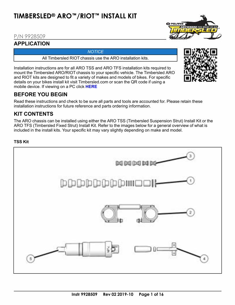
KIT CONTENTSThe ARO chassis can be installed using either the ARO TSS (Timbersled Suspension Strut) Install Kit or theARO TFS (Timbersled Fixed Strut) Install Kit. Refer to the images below for a general overview of what isincluded in the install kits. Your specific kit may vary slightly depending on make and model.
TSS Kit
Instr 9928509 Rev 02 2019-10 Page 1 of 16
P/N 9928509
TIMBERSLED®® ARO™™/RIOT™™ INSTALL KIT

Instr 9928509 Rev 02 2019-10 Page 2 of 16
REF QTY PART DESCRIPTION PART NUMBER1 1 Spacer Pack -
2 1 Fork Clamp -
3 1 Strut Rod Reducer Pack -
4 1 Strut Rod TSS -
5 1 TSS Shock Body -
1 Instructions 9928509
TFS Kit
REF QTY PART DESCRIPTION PART NUMBER1 1 Spacer Pack -
2 1 Fork Clamp -
3 1 Strut Rod Reducer Pack -
4 1 Strut - Solid, Adjustable -
1 Instructions 9928509
TOOLS REQUIRED• Safety Glasses• Hammer, Soft Face• Hex Key Set, Metric
• Pliers, Slip Joint• Screwdriver, Standard• Tin Snips, Straight Cut
Instr 9928509 Rev 02 2019-10 Page 3 of 16
• Socket Set, Hex Bit, Metric• Socket Set, Metric• Wrench Set, Metric
• Vehicle Lift/Support Equipment• Model Specific Timbersled ARO Fitment Table• Torque Wrench
IMPORTANTYour TIMBERSLED® ARO™/RIOT™ Install Kit is exclusively designed for your vehicle. Please read theinstallation instructions thoroughly before beginning. Installation is easier if the vehicle is clean and free ofdebris. For your safety, and to ensure a satisfactory installation, perform all installation steps correctly in thesequence shown.
INSTALLATION INSTRUCTIONS
The instructions listed are universal for all bikes usingthe Timbersled ARO/RIOTsnowbike kit. The processin the instructions may vary slightly between makesand models. Refer to your host bike’s owner’s manualfor specific references and assembly/disassemblyprocedures.You will also need a copy of the Timbersled FitmentTable for your specific bike model. The TimbersledFitment Table can be found and printed at Timbersled.com or by contacting your local Timbersled dealer.
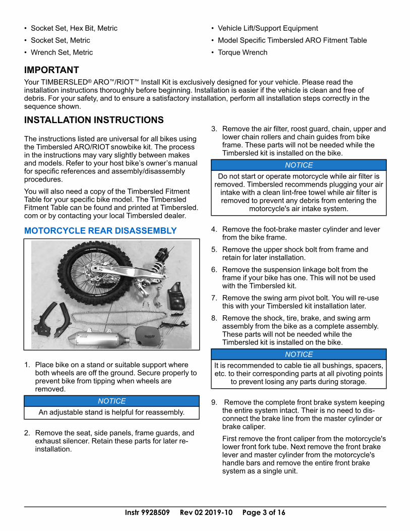
MOTORCYCLE REAR DISASSEMBLY
1. Place bike on a stand or suitable support whereboth wheels are off the ground. Secure properly toprevent bike from tipping when wheels areremoved.
NOTICEAn adjustable stand is helpful for reassembly.
2. Remove the seat, side panels, frame guards, andexhaust silencer. Retain these parts for later re-installation.
3. Remove the air filter, roost guard, chain, upper andlower chain rollers and chain guides from bikeframe. These parts will not be needed while theTimbersled kit is installed on the bike.
NOTICEDo not start or operate motorcycle while air filter isremoved. Timbersled recommends plugging your airintake with a clean lint-free towel while air filter isremoved to prevent any debris from entering the
motorcycle's air intake system.
4. Remove the foot-brake master cylinder and leverfrom the bike frame.
5. Remove the upper shock bolt from frame andretain for later installation.
6. Remove the suspension linkage bolt from theframe if your bike has one. This will not be usedwith the Timbersled kit.
7. Remove the swing arm pivot bolt. You will re-usethis with your Timbersled kit installation later.
8. Remove the shock, tire, brake, and swing armassembly from the bike as a complete assembly.These parts will not be needed while theTimbersled kit is installed on the bike.
NOTICEIt is recommended to cable tie all bushings, spacers,etc. to their corresponding parts at all pivoting points
to prevent losing any parts during storage.
9. Remove the complete front brake system keepingthe entire system intact. Their is no need to dis-connect the brake line from the master cylinder orbrake caliper.First remove the front caliper from the motorcycle'slower front fork tube. Next remove the front brakelever and master cylinder from the motorcycle'shandle bars and remove the entire front brakesystem as a single unit.

Instr 9928509 Rev 02 2019-10 Page 4 of 16
FRAME BUSHING AND SUB-FRAMEREDUCER INSTALLATIONThere are two different types of ARO/RIOT install kitsavailable. The TSS (Timbersled Suspension Strut)install kit and the TFS (Timbersled Fixed Strut) installkit. Installation procedures for the sub-frame bushingsand reducers are universal for either kit.
NOTICEYour ARO/RIOT pivot forging sub-frame comes withthe pivot bushings pre-installed. If install kit spacerpacks come with extra sub-frame pivot bushings youwill not need them for the ARO/RIOT installation.
1. Install the sub-frame reducers into their properlocation in the pivot forging.If reducer bushing is black in color, first place anO-ringB on each of the sub-frame reducersAused. Put a coating of grease on the inside of thebushing and the outside of the spacer/reducer andinstall them into the frame. They should slip inwithout interference.If the bushings are white in color and do not havea step in them for the O-ring, DO NOT install theO-ring, Grease is not needed on the white/cremebushings.
NOTICETo locate the sub-frame reducer positioning for yourspecific bike, refer to the Timbersled Fitment
Tables. Fitment tables can be found and printed atTimbersled.com or by contacting your local
Timbersled Dealer. Each of the sub-frame spacers/reducers will have a part number stamped on theend that will be its reference number on the fitment
table to show their location.
Instr 9928509 Rev 02 2019-10 Page 5 of 16
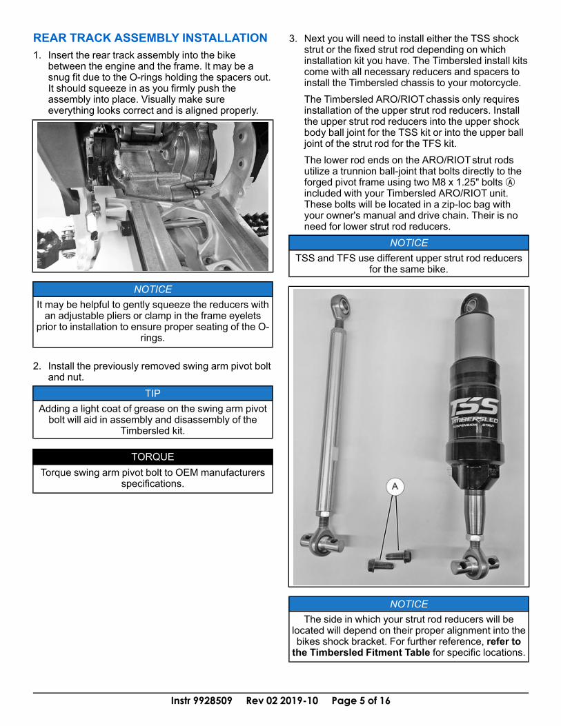
REAR TRACK ASSEMBLY INSTALLATION1. Insert the rear track assembly into the bike
between the engine and the frame. It may be asnug fit due to the O-rings holding the spacers out.It should squeeze in as you firmly push theassembly into place. Visually make sureeverything looks correct and is aligned properly.
NOTICEIt may be helpful to gently squeeze the reducers withan adjustable pliers or clamp in the frame eyelets
prior to installation to ensure proper seating of the O-rings.
2. Install the previously removed swing arm pivot boltand nut.
TIPAdding a light coat of grease on the swing arm pivotbolt will aid in assembly and disassembly of the
Timbersled kit.
TORQUETorque swing arm pivot bolt to OEM manufacturers
specifications.
3. Next you will need to install either the TSS shockstrut or the fixed strut rod depending on whichinstallation kit you have. The Timbersled install kitscome with all necessary reducers and spacers toinstall the Timbersled chassis to your motorcycle.The Timbersled ARO/RIOTchassis only requiresinstallation of the upper strut rod reducers. Installthe upper strut rod reducers into the upper shockbody ball joint for the TSS kit or into the upper balljoint of the strut rod for the TFS kit.The lower rod ends on the ARO/RIOTstrut rodsutilize a trunnion ball-joint that bolts directly to theforged pivot frame using two M8 x 1.25" boltsAincluded with your Timbersled ARO/RIOT unit.These bolts will be located in a zip-loc bag withyour owner's manual and drive chain. Their is noneed for lower strut rod reducers.
NOTICETSS and TFS use different upper strut rod reducers
for the same bike.
NOTICEThe side in which your strut rod reducers will be
located will depend on their proper alignment into thebikes shock bracket. For further reference, refer tothe Timbersled Fitment Table for specific locations.
Instr 9928509 Rev 02 2019-10 Page 6 of 16
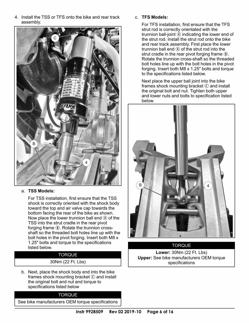
4. Install the TSS or TFS onto the bike and rear trackassembly.
a. TSS Models:For TSS installation, first ensure that the TSSshock is correctly oriented with the shock bodytoward the top and air valve cap towards thebottom facing the rear of the bike as shown.Now place the lower trunnion ball endr of theTSS into the strut cradle in the rear pivotforging frameB. Rotate the trunnion cross-shaft so the threaded bolt holes line up with thebolt holes in the pivot forging. Insert both M8 x1.25" bolts and torque to the specificationslisted below.
TORQUE30Nm (22 Ft. Lbs)
b. Next, place the shock body end into the bikeframes shock mounting bracketC and installthe original bolt and nut and torque tospecifications listed below
TORQUESee bike manufacturers OEM torque specifications
c. TFS Models:For TFS installation, first ensure that the TFSstrut rod is correctly orientated with thetrunnion ball-jointr indicating the lower end ofthe strut rod. Install the strut rod onto the bikeand rear track assembly. First place the lowertrunnion ball endr of the strut rod into thestrut cradle in the rear pivot forging frameB.Rotate the trunnion cross-shaft so the threadedbolt holes line up with the bolt holes in the pivotforging. Insert both M8 x 1.25" bolts and torqueto the specifications listed below.Next place the upper ball joint into the bikeframes shock mounting bracketC and installthe original bolt and nut. Tighten both upperand lower nuts and bolts to specification listedbelow.
TORQUELower: 30Nm (22 Ft. Lbs)
Upper: See bike manufacturers OEM torquespecifications
Instr 9928509 Rev 02 2019-10 Page 7 of 16
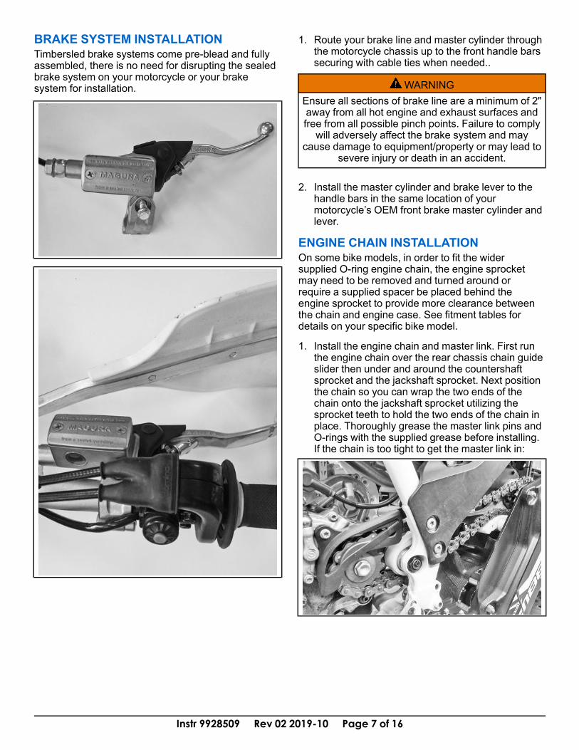
BRAKE SYSTEM INSTALLATIONTimbersled brake systems come pre-blead and fullyassembled, there is no need for disrupting the sealedbrake system on your motorcycle or your brakesystem for installation.
1. Route your brake line and master cylinder throughthe motorcycle chassis up to the front handle barssecuring with cable ties when needed..
WARNINGEnsure all sections of brake line are a minimum of 2"away from all hot engine and exhaust surfaces andfree from all possible pinch points. Failure to complywill adversely affect the brake system and may
cause damage to equipment/property or may lead tosevere injury or death in an accident.
2. Install the master cylinder and brake lever to thehandle bars in the same location of yourmotorcycle’s OEM front brake master cylinder andlever.
ENGINE CHAIN INSTALLATIONOn some bike models, in order to fit the widersupplied O-ring engine chain, the engine sprocketmay need to be removed and turned around orrequire a supplied spacer be placed behind theengine sprocket to provide more clearance betweenthe chain and engine case. See fitment tables fordetails on your specific bike model.
1. Install the engine chain and master link. First runthe engine chain over the rear chassis chain guideslider then under and around the countershaftsprocket and the jackshaft sprocket. Next positionthe chain so you can wrap the two ends of thechain onto the jackshaft sprocket utilizing thesprocket teeth to hold the two ends of the chain inplace. Thoroughly grease the master link pins andO-rings with the supplied grease before installing.If the chain is too tight to get the master link in:

Instr 9928509 Rev 02 2019-10 Page 8 of 16
a. First, loosen the two 15mm sub-frame pinchboltsA located on the right-hand side framerail.
b. Next, loosen the 13mm jam nut on thechassis's tensioner bolt. To achieve less chaintension thread the tensioner boltB in a clock-wise direction. This will pull the forged pivotforging into the frame rails to give you moreslack in the chain making it easier to install thechain master link. To achieve more chaintension, thread the tensioner bolt out in acounter-clockwise direction.
2. Install the O-ringsC and outer plateD by placingit on the pins and pressing it together with pliers.
3. Install the retaining clipE so that it is facingbackwards of rotation.
DRIVE CHAIN TENSIONFor long chain life and reliability, it is extremelyimportant that you keep the drive chain adjustedproperly. Always check drive chain tension beforeriding.
IMPORTANTTIMBERSLED SUSPENSION STRUT (TSS)
MODELS: The TSSMUST be at full extension andset to at least 200 PSI to measure and adjust drivechain tension properly. To ensure the TSS is at full
extension, remove all weight from the shock.Inspecting and adjusting a chain without the
suspension at full extension will indicate a loosechain and lead to over-tensioning and excessive
chain stretch and wear.
NOTICEThe drive chain may loosen on the first ride due toinitial chain stretch and slider break-in. Retightendrive chain after the first few rides. If the problem
persists, your dealer can assist.
MEASURING DRIVE CHAIN TENSIONTo measure drive chain tension before riding:
1. Ensure your snow bike is free of all snow anddebris, positioned on a flat even surface, and hasno wheel kit positioned under it.

Instr 9928509 Rev 02 2019-10 Page 9 of 16
For Timbersled Suspension Strut (TSS)models, set TSS shock air pressure to at least200 PSI. Then ensure TSS suspension is at fullextension (i.e. no weight is on the shocks) bytipping the bike on its side or by using anappropriate stand to lift the bike under its engineensuring the track is suspended off the ground.
2. Position a ruler behind or in front of the top chordof the drive chain, halfway between the countershaft sprocket and the jack shaft sprocket (this iswhere drive chain displacement should bemeasured)q. Steady the ruler so it does notmove as chain displacement is measured.
3. Choose a single chain link pin close to the ruler touse as a reference point for measuring chaindisplacement. Push down on the top chord of thechain with one finger and line up the 1 inch markon the ruler with the chosen chain pinw (seephoto).
4. Then, without moving the ruler, push up on the topchord of the chain with one finger in the samelocation and count the number of 1/8th in. marksbetween the 1 inch mark and the new position ofthe chosen chain pine.If the chain is properly tensioned, there should bebetween 0.75 in. and 0.25 in. between the 1 inchmark (the position of the chosen chain pin whenpressed down) and the current position of thechosen chain pin (when pressed up). This is thedrive chain’s displacement measurement. If thedrive chain’s displacement measurement is less ormore than 0.75 in. and 1.25 in.the chain needs tobe adjusted (see Adjusting Drive Chain Tension).
Instr 9928509 Rev 02 2019-10 Page 10 of 16
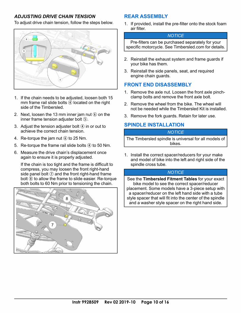
ADJUSTING DRIVE CHAIN TENSIONTo adjust drive chain tension, follow the steps below.
1. If the chain needs to be adjusted, loosen both 15mm frame rail slide boltsr located on the rightside of the Timbersled.
2. Next, loosen the 13 mm inner jam nuty on theinner frame tension adjuster boltt.
3. Adjust the tension adjuster boltr in or out toachieve the correct chain tension.
4. Re-torque the jam nuty to 25 Nm.5. Re-torque the frame rail slide boltsr to 50 Nm.6. Measure the drive chain’s displacement once
again to ensure it is properly adjusted.If the chain is too tight and the frame is difficult tocompress, you may loosen the front right-handside panel boltu and the front right-hand framebolti to allow the frame to slide easier. Re-torqueboth bolts to 60 Nm prior to tensioning the chain.
REAR ASSEMBLY1. If provided, install the pre-filter onto the stock foam
air filter.NOTICE
Pre-filters can be purchased separately for yourspecific motorcycle. See Timbersled.com for details.
2. Reinstall the exhaust system and frame guards ifyour bike has them.
3. Reinstall the side panels, seat, and requiredengine chain guards.
FRONT END DISASSEMBLY1. Remove the axle nut. Loosen the front axle pinch-
clamp bolts and remove the front axle bolt.2. Remove the wheel from the bike. The wheel will
not be needed while the Timbersled Kit is installed.3. Remove the fork guards. Retain for later use.
SPINDLE INSTALLATIONNOTICE
The Timbersled spindle is universal for all models ofbikes.
1. Install the correct spacer/reducers for your makeand model of bike into the left and right side of thespindle cross tube.
NOTICESee the Timbersled Fitment Tables for your exact
bike model to see the correct spacer/reducerplacement. Some models have a 3-piece setup witha spacer/reducer on the left hand side with a tubestyle spacer that will fit into the center of the spindleand a washer style spacer on the right hand side.

Instr 9928509 Rev 02 2019-10 Page 11 of 16
2. Place spindle assembly into position with theconcave side of the spindle facing towards the rearof the motorcycle. Slide in the stock front axle bolt(unless the fit kit is supplied with a Timbersledmachined axle) and install the nut. DO NOTTIGHTEN any of the front end fasteners at thistime.
3. Locate the inner fork clampsA and place themonto the inside face of the fork tubes in betweenthe fork tube and the spindle with the fork sealrelief groove facing up.
NOTICESome models require a shim washer between thespindle and the inner fork clamp. See notes in thefitment tables and install as necessary for your
specific bike.
4. Slide both inner fork clampsA (less fork clampcap) down between the spindle and fork tubes.Position them as low as possible on the fork tube.
NOTICESlide the brake-side clamp down on the fork tube aslow as it will go first, then set the opposing side.
Ensure that both left and right fork clamps are sittingat the same height.
5. Install the plastic split bushingB onto the forktubes above the clamps with the bushing flange onthe top. Slide the bushing down into the forkclamps so that bushing flange is all the way downinside the relief groove.
Instr 9928509 Rev 02 2019-10 Page 12 of 16
6. Rotate the spindle forward and back until the forkclamp bolt holes line up with the slotted spindleholes. This will properly set the correct amount oftrailing the ski will have in relation to the axle bolt.
NOTICETo help hold the spindle in place while you work on ityou can snug the axle nut and set the spindle on theground. You can then tap the spindle back and forth
to get the correct positioning.
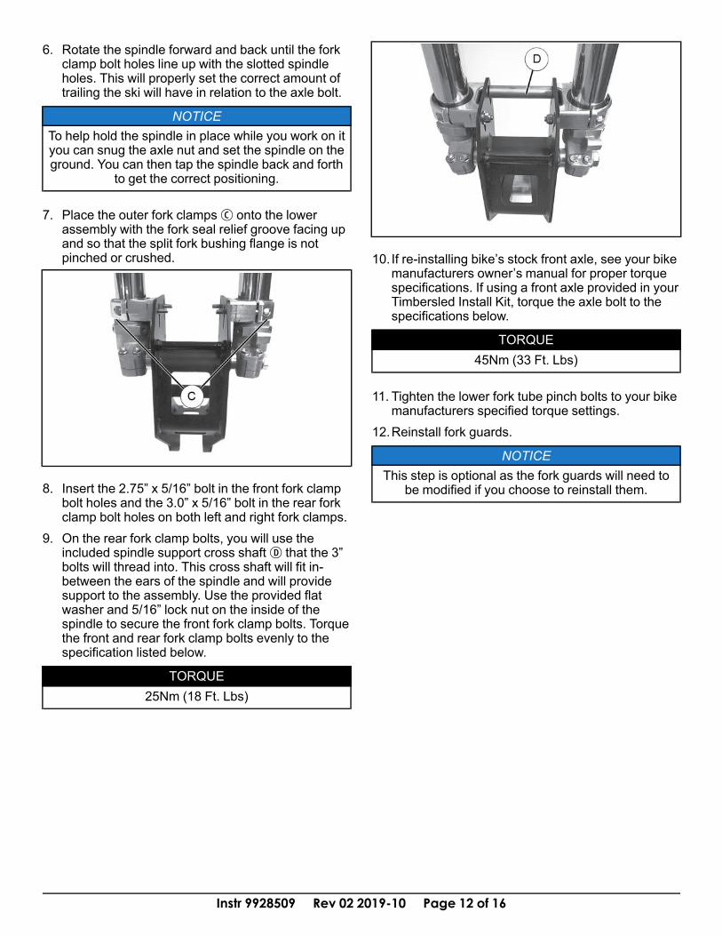
7. Place the outer fork clampsC onto the lowerassembly with the fork seal relief groove facing upand so that the split fork bushing flange is notpinched or crushed.
8. Insert the 2.75” x 5/16” bolt in the front fork clampbolt holes and the 3.0” x 5/16” bolt in the rear forkclamp bolt holes on both left and right fork clamps.
9. On the rear fork clamp bolts, you will use theincluded spindle support cross shaftD that the 3”bolts will thread into. This cross shaft will fit in-between the ears of the spindle and will providesupport to the assembly. Use the provided flatwasher and 5/16” lock nut on the inside of thespindle to secure the front fork clamp bolts. Torquethe front and rear fork clamp bolts evenly to thespecification listed below.
TORQUE25Nm (18 Ft. Lbs)
10. If re-installing bike’s stock front axle, see your bikemanufacturers owner’s manual for proper torquespecifications. If using a front axle provided in yourTimbersled Install Kit, torque the axle bolt to thespecifications below.
TORQUE45Nm (33 Ft. Lbs)
11. Tighten the lower fork tube pinch bolts to your bikemanufacturers specified torque settings.
12.Reinstall fork guards.
NOTICEThis step is optional as the fork guards will need to
be modified if you choose to reinstall them.
Instr 9928509 Rev 02 2019-10 Page 13 of 16
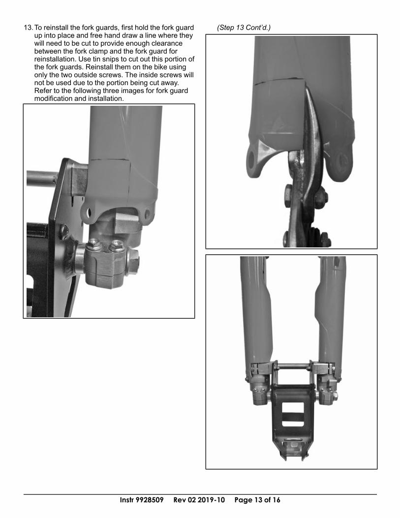
13.To reinstall the fork guards, first hold the fork guardup into place and free hand draw a line where theywill need to be cut to provide enough clearancebetween the fork clamp and the fork guard forreinstallation. Use tin snips to cut out this portion ofthe fork guards. Reinstall them on the bike usingonly the two outside screws. The inside screws willnot be used due to the portion being cut away.Refer to the following three images for fork guardmodification and installation.
(Step 13 Cont’d.)
Instr 9928509 Rev 02 2019-10 Page 14 of 16
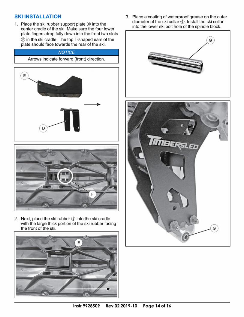
SKI INSTALLATION1. Place the ski rubber support plateD into the
center cradle of the ski. Make sure the four lowerplate fingers drop fully down into the front two slotsF in the ski cradle. The top T-shaped ears of theplate should face towards the rear of the ski.
NOTICEArrows indicate forward (front) direction.
2. Next, place the ski rubberE into the ski cradlewith the large thick portion of the ski rubber facingthe front of the ski.
3. Place a coating of waterproof grease on the outerdiameter of the ski collarG. Install the ski collarinto the lower ski bolt hole of the spindle block.
Instr 9928509 Rev 02 2019-10 Page 15 of 16
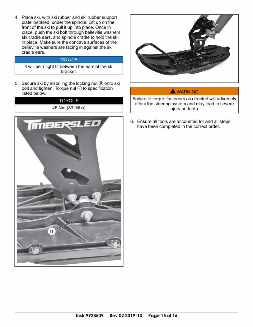
4. Place ski, with ski rubber and ski rubber supportplate installed, under the spindle. Lift up on thefront of the ski to pull it up into place. Once inplace, push the ski bolt through belleville washers,ski cradle ears, and spindle cradle to hold the skiin place. Make sure the concave surfaces of thebelleville washers are facing in against the skicradle ears.
NOTICEIt will be a tight fit between the ears of the ski
bracket.
5. Secure ski by installing the locking nutH onto skibolt and tighten. Torque nutH to specificationlisted below.
TORQUE45 Nm (33 ft/lbs)
WARNINGFailure to torque fasteners as directed will adverselyaffect the steering system and may lead to severe
injury or death.
6. Ensure all tools are accounted for and all stepshave been completed in the correct order.

Instr 9928509 Rev 02 2019-10 Page 16 of 16
FEEDBACK FORMA feedback form has been created for the installer to provide any comments, questionsor concerns about the installation instructions. The form is viewable on mobile devicesby scanning the QR code or by clicking HERE if viewing on a PC.
FEEDBACK FORM