tier 2 site cleanup report guidance
TRANSCRIPT

TIER 2 SITE CLEANUP REPORT GUIDANCE
Site Assessment of Leaking Underground Storage Tanks Using Risk-Based Corrective Action
Underground Storage Tank Section Iowa Department of Natural Resources
502 East 9th Street Des Moines, IA 50319-0034
(515) 725-8200www.iowadnr.gov/ust
January 2018

CHAPTER 1 RISK BASED CORRECTIVE ACTION OVERVIEW .......................................................... 1-1 General Information ............................................................................................................................ 1-1 Statutory Authority .............................................................................................................................. 1-1 Conditions Requiring Submittal of a Tier 2 Report............................................................................... 1-1 Financial Responsibility....................................................................................................................... 1-2 Iowa Comprehensive Petroleum UST Fund Program .......................................................................... 1-2 Tier 2 Site Assessment Overview ....................................................................................................... 1-2 Tier 2 Web-based Application ............................................................................................................. 1-2 Tier 2 Report Form .............................................................................................................................. 1-3 Tier 2 Report Preparation & Submittal ................................................................................................. 1-3 Tier 2 Application ................................................................................................................................ 1-3 Tier 2 Report Submittal ....................................................................................................................... 1-3 Report Submittal Schedule ................................................................................................................. 1-3 Quality Control/Quality Assurance Procedures ................................................................................... 1-4 Chemicals of Concern ......................................................................................................................... 1-4
Benzene, Toluene, Ethylbenzene, Xylenes ..................................................................................... 1-4 Total Extractable Hydrocarbons ...................................................................................................... 1-4 Methyl-tertiary Butyl Ether ............................................................................................................... 1-4 Other Chemicals of Concern ........................................................................................................... 1-5
Certified Laboratory Required ............................................................................................................. 1-5 Laboratory Data Sheets ...................................................................................................................... 1-5 Soil Gas Analysis ................................................................................................................................ 1-5 Soil Gas Sampling .............................................................................................................................. 1-5
Collecting a Soil Gas Sample .......................................................................................................... 1-6 Checking the Static Water Levels .................................................................................................... 1-7
Indoor Air Sampling ............................................................................................................................ 1-8 Report Review Procedures ................................................................................................................. 1-9 Site Classification ................................................................................................................................ 1-9 No Action Required Site Classification ................................................................................................ 1-9 Plugging Abandoned Wells & Borings ............................................................................................... 1-10 No Further Action Certificate ............................................................................................................. 1-10 Tier 3 Assessment ............................................................................................................................ 1-10 Expedited Corrective Action .............................................................................................................. 1-10 Free Product Recovery ..................................................................................................................... 1-11
CHAPTER 2 CONTAMINANT PLUME SIMULATION ............................................................................ 2-1
Groundwater Model Overview ............................................................................................................. 2-1 Contaminant Concentrations ........................................................................................................... 2-1 Source............................................................................................................................................. 2-2
Soil Vapor Model................................................................................................................................. 2-2 Soil Leaching to Groundwater Model .................................................................................................. 2-2 Model Parameters ............................................................................................................................... 2-2 Hydraulic Conductivity Parameter ....................................................................................................... 2-2 Source Width for Groundwater Transport Modeling ............................................................................ 2-3 Source Width & Length for Soil Leaching to Groundwater Transport Modeling ................................... 2-3 Source Width & Length in the Presence of Free Product .................................................................... 2-4 Simulation Line ................................................................................................................................... 2-4 Site-Specific Target Level (SSTL) Line ............................................................................................... 2-4 Cross-gradient and Up-gradient Modeling Considerations .................................................................. 2-4 Plume Definition .................................................................................................................................. 2-5 Pathway Completeness ...................................................................................................................... 2-6 Points of Exposure and Compliance ................................................................................................... 2-6 Group Two Chemicals ........................................................................................................................ 2-6
CHAPTER 3 ROUTINE ASSESSMENT PROCEDURES ....................................................................... 3-1 Groundwater Ingestion Pathway Assessment ..................................................................................... 3-1
Pathway Completeness ................................................................................................................... 3-1 Receptor Evaluation ........................................................................................................................ 3-1 Pathway Evaluation ......................................................................................................................... 3-2 Target Levels .................................................................................................................................. 3-3 Modeling ......................................................................................................................................... 3-4 Plume Definition .............................................................................................................................. 3-4 Pathway Classification .................................................................................................................... 3-4 Corrective Action Response ............................................................................................................ 3-4 Use of Institutional Controls ............................................................................................................. 3-5 Water Supply Notification ................................................................................................................ 3-5
Soil Leaching to Groundwater Pathway Assessment .......................................................................... 3-5 General ........................................................................................................................................... 3-5 Pathway Completeness ................................................................................................................... 3-5 Receptor Evaluation ........................................................................................................................ 3-6 Plume Definition .............................................................................................................................. 3-7 Modeling & Target Levels ................................................................................................................ 3-7 Risk Classification for Soil Leaching ................................................................................................ 3-7
Groundwater Vapor to Enclosed Space Pathway Assessment.......................................................... 3-10 Pathway Completeness ................................................................................................................. 3-10 Explosive Vapor Survey ................................................................................................................ 3-10 Receptors of Concern ................................................................................................................... 3-11 Plume Definition ............................................................................................................................ 3-12 Target Levels for Groundwater ...................................................................................................... 3-12 Target Levels for Vapor ................................................................................................................. 3-14 Pathway Evaluation ....................................................................................................................... 3-14 Pathway Classification .................................................................................................................. 3-16 Corrective Action Response .......................................................................................................... 3-17 Sanitary Sewer Notification ........................................................................................................... 3-17 Use of Institutional Controls ........................................................................................................... 3-18
Soil Vapor to Enclosed Space Pathway Assessment ........................................................................ 3-18 Pathway Completeness ................................................................................................................. 3-18 Explosive Vapor Survey ................................................................................................................ 3-18 Receptors of Concern ................................................................................................................... 3-18 Plume Definition ............................................................................................................................ 3-20 Establishing Target Levels for Soil ................................................................................................ 3-20 Target Levels for Vapor ................................................................................................................. 3-21 Pathway Evaluation ....................................................................................................................... 3-22 Pathway Classification .................................................................................................................. 3-23 Corrective Action Response .......................................................................................................... 3-24 Sanitary Sewer Notification ........................................................................................................... 3-24 Use of Institutional Controls ........................................................................................................... 3-25
Groundwater to Water Line Pathway................................................................................................. 3-26 Actual Receptors ........................................................................................................................... 3-26 Potential Receptors ....................................................................................................................... 3-26 Plume Definition ............................................................................................................................ 3-26 Groundwater to Water Line target levels ....................................................................................... 3-26 Water Line Sampling ..................................................................................................................... 3-26 Receptor ID Maps ......................................................................................................................... 3-27 Pathway Classification .................................................................................................................. 3-27 Water Line - Utility Company Notification ...................................................................................... 3-27 Water Lines in Free Product Areas ................................................................................................ 3-27 Corrective Action Response .......................................................................................................... 3-27

Soil to Water Line Pathway ............................................................................................................... 3-28 Actual Receptors ........................................................................................................................... 3-28 Potential Receptors ....................................................................................................................... 3-28 Plume Definition ............................................................................................................................ 3-28 Soil to Water Line Target Levels.................................................................................................... 3-28 Soil to Water Line Receptor ID Maps ............................................................................................ 3-29 Pathway Classification .................................................................................................................. 3-29 Water Line -Utility Company Notification ....................................................................................... 3-29 Water Lines in Free Product Areas ................................................................................................ 3-29 Corrective Action ........................................................................................................................... 3-29 Evaluating the Soil to Water Line Pathway in Tier 3 ...................................................................... 3-30
Surface Water Pathway Assessment ................................................................................................ 3-30 Surface Water Use Classification .................................................................................................. 3-30 Pathway Completeness ................................................................................................................. 3-32 Visual Inspection ........................................................................................................................... 3-32 Receptor Evaluation ...................................................................................................................... 3-32 Plume Definition ............................................................................................................................ 3-34 Target Levels ................................................................................................................................ 3-34 Pathway Classification .................................................................................................................. 3-35 Corrective Action Response .......................................................................................................... 3-36
CHAPTER 4 BEDROCK ASSESSMENT ............................................................................................... 4-1
Categories for Special Bedrock Assessment ....................................................................................... 4-1 Non-granular Bedrock ..................................................................................................................... 4-2 Granular Bedrock ............................................................................................................................ 4-2 Exempt Granular Bedrock ............................................................................................................... 4-2
Special Procedures for Granular and Non-granular Bedrock ............................................................... 4-3 Protected Groundwater Source ....................................................................................................... 4-3 Soil and Soil Leaching to Groundwater Pathways ........................................................................... 4-3 Remediation of Soil Contamination ................................................................................................. 4-3 Initial Groundwater Assessment ...................................................................................................... 4-3
Special Procedures for the Groundwater Ingestion Pathway at Granular and Non-granular Bedrock Sites.................................................................................................................................................... 4-4
Groundwater Plume Definition ......................................................................................................... 4-4 Groundwater Well Receptor Evaluation ........................................................................................... 4-4 Target Levels .................................................................................................................................. 4-4 Sentry Well (Only For Sites Designated As Granular Bedrock) ....................................................... 4-4 High Risk Classification ................................................................................................................... 4-5 Low Risk Classification .................................................................................................................... 4-5 No Action Required ......................................................................................................................... 4-5
Special Procedures for the Groundwater Vapor to Enclosed Space Pathway ..................................... 4-5 Soil Gas Plume ............................................................................................................................... 4-5 High Risk Classification ................................................................................................................... 4-6 Low Risk Classification .................................................................................................................... 4-6
Special Procedures for the Groundwater to Water Line Pathway ........................................................ 4-6 Target Level .................................................................................................................................... 4-6 Sampling Water Lines ..................................................................................................................... 4-6 High Risk Classification ................................................................................................................... 4-6
Special Procedures for the Surface Water Pathway for Granular and Non-granular Bedrock Sites ..... 4-6 Point of compliance .................................................................................................................. 4-6 High risk classification .............................................................................................................. 4-7 Low risk classification ............................................................................................................... 4-7
High Risk Corrective Action Response for Granular and Non-granular Bedrock Sites ......................... 4-7

Groundwater Ingestion Pathway...................................................................................................... 4-7 Water Lines Pathways ..................................................................................................................... 4-7 Other Pathways ............................................................................................................................... 4-8 Receptor Sampling .......................................................................................................................... 4-8
Monitoring ........................................................................................................................................... 4-8 Groundwater in Non-granular Bedrock ............................................................................................ 4-8 Groundwater in Granular Bedrock ................................................................................................... 4-8 Soil Gas for the Groundwater Vapor Pathway ................................................................................. 4-8
No Action Required Classification ....................................................................................................... 4-8 Groundwater in Non-granular Bedrock ............................................................................................ 4-8 Groundwater in Granular Bedrock ................................................................................................... 4-9 Soil Gas .......................................................................................................................................... 4-9 Monitoring Well Plugging ................................................................................................................. 4-9
CHAPTER 5 TIER 2 & 3 SITE CLASSIFICATION AND CORRECTIVE ACTION RESPONSE .............. 5-1
Risk Classification ............................................................................................................................... 5-1 General ........................................................................................................................................... 5-1 High & Low Risk Classification - Groundwater and Soil Leaching to Groundwater Pathways .......... 5-1 High & Low Risk Classification-Soil Pathways ................................................................................. 5-3 No Action Required Classification-All Pathways .............................................................................. 5-3 Reclassification-All Pathways .......................................................................................................... 5-4
High Risk Corrective Action Response ................................................................................................ 5-4 Objectives ....................................................................................................................................... 5-4 Soil Corrective Action Response ..................................................................................................... 5-5 Corrective Action Conferences ........................................................................................................ 5-5 Corrective Action Design Report ..................................................................................................... 5-6 Interim Monitoring at High Risk Sites ............................................................................................... 5-6 Remediation monitoring .................................................................................................................. 5-6 Completion of Corrective Action ...................................................................................................... 5-6
Low Risk Corrective Action Response ................................................................................................ 5-6 Annual Monitoring ............................................................................................................................... 5-7
General Groundwater Monitoring .................................................................................................... 5-7 Monitoring Actual Groundwater Receptors ...................................................................................... 5-9 Monitoring Drinking & Non-drinking Water Wells ............................................................................. 5-9 Monitoring Water Lines ................................................................................................................. 5-10 Monitoring Potential Groundwater Receptors- General ................................................................. 5-10 Steps for Developing a Monitoring Plan for a Protected Groundwater Source ............................... 5-10 Steps for Developing a Monitoring Plan for Potential Groundwater Vapor Receptors .................... 5-12 Monitoring Actual Soil Leaching Receptors ................................................................................... 5-15 Monitoring Potential Soil Leaching Receptors ............................................................................... 5-16 Soil Monitoring .............................................................................................................................. 5-16 Monitoring Non-granular Bedrock Sites ......................................................................................... 5-17 Monitoring Granular Bedrock Sites ................................................................................................ 5-17 MtBE Monitoring ............................................................................................................................ 5-17
Use of Technological and Institutional Controls ................................................................................. 5-18 Technological Controls .................................................................................................................. 5-18 Institutional Controls ...................................................................................................................... 5-18
City and County Well Ordinances ..................................................................................................... 5-19 Local Ordinances as Institutional Controls for Groundwater Ingestion Pathways ........................... 5-19 Local Ordinance Regulating on the Basis of Availability of Public Water Supply ............................ 5-20
Environmental Covenant ................................................................................................................... 5-21 Pathway-specific Environmental Covenants .................................................................................. 5-22 Special Bedrock Conditions ........................................................................................................... 5-23

Modification or Termination of Institutional Controls .......................................................................... 5-24 Soil Excavation as Expedited Corrective Action at Tier 2 .................................................................. 5-24
Conducting Soil Excavation ........................................................................................................... 5-25 Excavation Reporting .................................................................................................................... 5-25 Petroleum Contaminated Soil Disposal ......................................................................................... 5-26 Revising the Tier 2 Application After Excavation ........................................................................... 5-26
Plugging Drinking and Non-drinking Water Wells .............................................................................. 5-26 Replacement or Relocation of Water Lines ....................................................................................... 5-26 Free Product ..................................................................................................................................... 5-27
Response to Notification of Free Product ...................................................................................... 5-28 Active Remediation or Recovery of Free Product .......................................................................... 5-30 Termination of Active Free Product Recovery ............................................................................... 5-30 Termination of Free Product Reporting and Initiation of Free Product Inspection .......................... 5-30 Terminating Free Product Inspections ........................................................................................... 5-30 No Further Action Certificate after Termination of Free Product Activities ..................................... 5-30
Monitoring Certificates and No Further Action Certificates ................................................................ 5-31 Monitoring Certificate .................................................................................................................... 5-31 No Further Action Certificate ......................................................................................................... 5-31
Tier 3 Site Assessment ..................................................................................................................... 5-32 Tier 3 Work Plan ........................................................................................................................... 5-32 Tier 3 Report ................................................................................................................................. 5-33 Tier 3: Substitution of an Actual Plume for a Simulated Plume ...................................................... 5-33 Well and Aquifer Vulnerability at Tier 3 .......................................................................................... 5-33 Use of Alternative Modeling at Tier 3 ............................................................................................. 5-33
CHAPTER 6 COMPLETING THE TIER 2 FORM ................................................................................... 6-1
Cover Page ......................................................................................................................................... 6-1 Tier 2 Report Checklist........................................................................................................................ 6-1 Summary Pages ................................................................................................................................. 6-2
Tier 2 Data Before Modeling ............................................................................................................ 6-2 Site Hydrogeology ........................................................................................................................... 6-2 Preliminary Pathway Evaluation Requirements ............................................................................... 6-2 Tier 2 Receptor Summary ............................................................................................................... 6-2
Report Body ........................................................................................................................................ 6-3 Sampling Results ............................................................................................................................ 6-3
Receptor Survey ................................................................................................................................. 6-5 Water Well Survey .......................................................................................................................... 6-5 Affected Property Owner Table ....................................................................................................... 6-5 Commingled Plume Discussion ....................................................................................................... 6-5 Off-site Contamination Support Discussion ..................................................................................... 6-5 Free Product ................................................................................................................................... 6-6 Enclosed Space/Conduit Survey ..................................................................................................... 6-6 Explosive Vapor Survey .................................................................................................................. 6-6 Surface Water Survey ..................................................................................................................... 6-6 Risk Justification & Corrective Action Proposed .............................................................................. 6-7 Monitoring Plan ............................................................................................................................... 6-7
Pathway Assessment Attachments ..................................................................................................... 6-8 Groundwater Pathway Assessment-General Procedure .................................................................. 6-8 Groundwater Receptor ID plume ..................................................................................................... 6-8 Groundwater Receptor Evaluation Map ........................................................................................... 6-9 Groundwater SSTL Tables ............................................................................................................ 6-10 Soil Leaching Receptor ID Plume .................................................................................................. 6-10 Soil SSTL Tables .......................................................................................................................... 6-11

Soil Vapor to Enclosed Space ....................................................................................................... 6-11 Soil to Water Line .......................................................................................................................... 6-11
Tier 2 Bedrock Assessment Form ..................................................................................................... 6-11 Required Sections for All Bedrock Types ...................................................................................... 6-11 Granular & Non-granular Bedrock Tier 2 Report Form .................................................................. 6-13 Bedrock Pathway Assessment Attachments ................................................................................. 6-14
Other Maps ....................................................................................................................................... 6-16 Other Appendices ............................................................................................................................. 6-19
APPENDICIES ............................................................................................................................................
Appendix A - Tier 1 Look-up Table, Assumptions, Equations and Parameter Values ......................... A-1 Groundwater Ingestion Equations .................................................................................................. A-2 Soil Leaching to Groundwater Equations ........................................................................................ A-2 Soil Vapor to Enclosed Space Equations ....................................................................................... A-2 Indoor Air Inhalation Equations ...................................................................................................... A-2 Groundwater Vapor to Enclosed Space Equations ......................................................................... A-3 Variable Definitions ........................................................................................................................ A-3 Soil and Groundwater Parameter Values Used for Iowa Tier 1 Table Generation .......................... A-4 Exposure Factors Used in Iowa Tier 1 Table Generation ............................................................... A-4 Building Parameters Used in Iowa Tier 1 Table Generation ........................................................... A-5 Chemical-Specific Parameter Values Used for Iowa Tier 1 Table Generation ................................ A-5 Saturation Values Used to Determine "NA" for the Iowa Tier 1 Table ............................................. A-5 Slope Factors and Reference Doses Used for Iowa Tier 1 Table Generation ................................. A-6
Appendix B – Tier 2 Equations and Parameter Values ....................................................................... B-1 Variable definitions ......................................................................................................................... B-1 Soil parameters .............................................................................................................................. B-1 Groundwater Transport Modeling Parameters ................................................................................ B-2 Other Parameters for Groundwater Vapor to Enclosed Space ....................................................... B-2 Other Parameters for Soil Vapor to Enclosed Space ...................................................................... B-3 Soil Leaching to Groundwater ........................................................................................................ B-3 Other Parameters ........................................................................................................................... B-3 Diesel and Waste Oil ...................................................................................................................... B-3
Appendix C – Declaration of Restrictive Covenants ........................................................................... C-1 Appendix D – No Further Action Certificate ........................................................................................ D-1 Appendix E – Field Office Contact Information ................................................................................... E-1 Appendix F – Bedrock Less Than 50 Feet Deep .................................................................................F-1 Appendix G – Abbreviations and Glossary ......................................................................................... G-1 Appendix H – Blank Forms ................................................................................................................ H-1 Appendix I – Quick links ....................................................................................................................... I-1 Appendix J – Additional Information on Water Lines ........................................................................... J-1 Appendix K – Transition Guidelines for the Water Line Pathway ........................................................ K-1 Appendix L – Revision Dates .............................................................................................................. L-1

CHAPTER 1 RISK BASED CORRECTIVE ACTION OVERVIEW
General Information The Iowa Department of Natural Resources (DNR) Underground Storage Tank (UST) Section utilizes risk based corrective action (RBCA), which assesses the risk(s) posed by petroleum contamination using site-specific conditions and a tiered approach to protect human health and the environment. Based on the results of the tiered assessment provided in a Tier 1 Report, Tier 2 Site Cleanup Report (Tier 2 Report), or Tier 3 Report, corrective action can be used to minimize or remove risk(s).
Corrective action options can include reducing contamination through active or passive methods, removing or relocating a receptor, using technological or institutional controls, or monitoring. In accordance with Iowa Administrative Code (IAC) 567-135.10(11)g, the DNR may, in the interest of minimizing environmental or public health risks and promoting a more effective cleanup, require owners and operators to begin cleanup of soil and groundwater before a Report is approved.
Statutory Authority The Iowa Code Chapter 455B and IAC Chapters 134 and 135 authorize the DNR to regulate underground storage tanks. Chapter 134 of the IAC requires a person who provides subsurface soil contamination and groundwater consulting services or who contracts to perform or supervise remediation or corrective action services at leaking underground storage tank sites be a certified groundwater professional (CGP). A list of certified groundwater professionals may be obtained from the DNR UST webpage.
Conditions Requiring Submittal of a Tier 2 Report A Tier 2 site assessment must be conducted and a Tier 2 Report submitted for all sites when any of the following conditions are present:
Free phase petroleum product.
The responsible party decides to bypass the Tier 1 assessment and go directly to the Tier 2 site assessment.
Failure of a Tier 1 pathway.
Bedrock is encountered above groundwater.
Explosive vapor levels are documented.
The following flow chart illustrates when a Tier 2 assessment is required:
Free Product Discovered at the Site
Failed Tier 1 Pathway Assessment
Responsible Party Decides to do a Tier 2 Assessment
Explosive Vapors
Bedrock Encountered Above Groundwater
Tier 2 Assessment

CHAPTER 1 RISK BASED CORRECTIVE ACTION OVERVIEW
1-2
Financial Responsibility Owners and operators of regulated underground storage tank systems are required to maintain financial responsibility or insurance. Owners and operators should contact their insurance carrier to begin the claim process when a release has been identified.
Iowa Comprehensive Petroleum UST Fund Program In addition to financial responsibility by owners or operators, the Iowa Comprehensive Petroleum Underground Storage Tank Fund Program may assist eligible parties with assessment and corrective action activities. Eligibility is determined on a site-specific, fund-specific basis. The DNR does not manage this program nor determine fund eligibility. Please contact the office of the Fund Administrator at AON Risk Services for additional information.
AON Risk Services 2700 Westown Pkwy Ste 320 West Des Moines IA 50266 (515) 225-9263 Or (515) 440-7016
A party eligible to receive Iowa Comprehensive Petroleum Underground Storage Tank Fund funds covering site investigation expenses must submit a budget prior to initiating work. Failure to receive budget approval prior to starting work at the site may result in a loss of state benefit eligibility.
Tier 2 Site Assessment Overview In this guidance:
Tier 2 Site Assessment refers to the process of investigating and determining risk to human health and the environment from contamination at a leaking underground storage tank (LUST) site.
Tier 2 Report refers to the form submitted to DNR.
Tier 2 Model refers to the web-based application used to tabulate the site data and assign risk based on modeling.
Tier 2 refers to the Tier 2 stage of site assessment.
The objective of a Tier 2 site assessment is to collect site-specific data and, with the use of Tier 2 modeling, to provide a Tier 2 Report to document whether actual or potential receptor(s) could be impacted by chemical(s) of concern. The Tier 2 model predicts what concentration(s) or site specific target levels (SSTLs) must be achieved at the source and between the source and the receptor(s) to ensure protection of the receptor(s).
Even if cleared at Tier 1, pathways may need to be evaluated at Tier 2. This is because pathway completeness for most pathways at Tier 2 depends on the extent of contamination (measured or simulated) rather than a set distance.
Tier 2 Web-based Application Tier 2 data analysis must be conducted using the most recent version of the DNR Tier 2 fate and transport web-based application (application). The Tier 2 Guidance along with the application will help complete a Tier 2 Site Cleanup Report.

CHAPTER 1 RISK BASED CORRECTIVE ACTION OVERVIEW
1-3
The Tier 2 application can be obtained on the DNR UST webpage.
A copy of the Tier 2 Software Manual is also available on the DNR UST webpage.
Tier 2 Report Form When a Tier 2 site assessment is conducted, findings must be presented in the Tier 2 Report form. A copy of the report form can be found on the DNR UST webpage.
The Tier 2 report cover page must be signed by the responsible party or a person contracting for the work and a CGP.
Tier 2 Report Preparation & Submittal All data obtained during the Tier 2 site assessment must be collected by or under the supervision of an Iowa certified groundwater professional. The responsible party must submit a signed copy of the Tier 2 report within 180 days of the confirmed release or other schedule approved by the DNR.
Send a signed copy of the Tier 2 report to: Iowa DNR LUST Coordinator 502 E 9th St Des Moines, IA 50319
Tier 2 Application The Tier 2 application must be submitted with the report. Click “Submit” not just “Save”. Report submittal is not considered complete until both the Tier 2 Report and application are received.
Tier 2 Report Submittal The completed Tier 2 Report must be accompanied by all required data, attachments, maps, and appendices as described in Chapter 6. Title and number each document as directed and attach the documents in the same order as stated. Ensure all maps are legible, have a north arrow, scale and legend. Additional data collected prior to the RBCA assessment should be included or incorporated into the Tier 2.
A checklist of all the components of the Tier 2 Report is included with the form to assist with report compilation. Items which may not be necessary for all reports are labeled "optional". It is the responsibility of the CGP to determine which site-specific information is to be included to produce a complete and accurate report. Incomplete Tier 2 Reports and Tier 2 Reports not submitted in the format required by this document will be rejected.
Report Submittal Schedule The expectation is that Tier 1 Reports will be submitted in 90 days and Tier 2 Reports will be submitted in 180 days. The timing for the submittal of the report starts when the letter requiring the evaluation is received by the responsible party (RP).
If during the Tier 1 evaluation phase of the project it is determined a Tier 2 evaluation is more appropriate, the CGP or RP must inform the DNR, in writing, of changes in the report submittal schedule. The request must provide a detailed reason for the extension. The DNR will evaluate the request.
CHAPTER 1 RISK BASED CORRECTIVE ACTION OVERVIEW
1-4
Quality Control/Quality Assurance Procedures The quality control/quality assurance (QC/QA) procedures used during the site investigation must be at least as stringent as those contained in DNR's LUST Quality Assurance Plan. A copy of the DNR's LUST Quality Assurance Plan may be found on the DNR UST webpage. See also the DNR-wide QC/QA procedures as an additional resource. The groundwater professional must provide DNR a copy of the QC/QA plan designed for the site and field notes on request.
Chemicals of Concern Benzene, Toluene, Ethylbenzene, Xylenes All soil and groundwater sample(s) collected from a release(s) of a petroleum-regulated substance(s) must be analyzed for volatile petroleum hydrocarbons-benzene, toluene, ethylbenzene, and xylenes (BTEX) per Iowa Method OA-1.
Total Extractable Hydrocarbons If the release is suspected to include any petroleum-regulated substance other than gasoline or gasoline blends, or if the source of the release is unknown, all soil and groundwater samples must also be tested for semi-volatile petroleum compounds-all grades of diesel fuel, fuel oil, kerosene oil, jet fuel, hydraulic fluid, and mineral spirits-Total Extractable Hydrocarbons (TEH) per Iowa Method OA-2.
A copy of Iowa Method OA-1 and OA-2 is available from the State Hygienic Lab or on the DNR UST webpage. For more information on chemicals of concern, refer to IAC 567-135.8(3).
Methyl-tertiary Butyl Ether All groundwater sample(s) collected during any phase of the RBCA evaluation process must be tested for methyl-tertiary butyl ether (MtBE) pursuant to IAC 567-135.19. The MtBE analyses must be performed regardless of what type of petroleum release (i.e., gasoline, diesel, fuel oil, waste oil, motor oil, hydraulic fluid, jet fuel, kerosene, and mineral spirits) is under investigation.
Laboratories analyzing for MtBE must be able to meet a detection level of 15 µg/L (ppb) for water samples. MtBE is considered not present if reported as <15 ppb. MtBE is considered present if 1) the lab reports it as a positive quantified level below 15 ppb (e.g., 12 ppb) by using a detection level below 15 ppb, or 2) if the laboratory is reporting at a higher detection level (e.g., <16 ppb, <50 ppb, <200 ppb). Under these conditions, continued monitoring for MtBE is required.
To assure reliable and accurate analytical results, MtBE analysis will be conducted by Gas Chromatography/Mass Spectrometry (GC/MS) using the GC/MS version of OA-1, "Method for Determination of Volatile Petroleum Hydrocarbons (gasoline)”, revision 7/27/93, or US Environmental Protection Agency Method 8260B, SW-846, "Test Methods for Evaluating Solid waste”, Third Edition. Using gas chromatography as the sole analytical method will likely result in a false positive (or negative) and should be reported to the DNR.
Laboratories performing the analyses must run standards for MtBE on a routine basis as well as standards for other possible compounds like ethyl tertiary-butyl ether (ETBE), tertiary-amyl methyl ether (TAME), di-isopropyl ether (DIPE), and tertiary-butyl alcohol (TBA) to be certain of their identification should they be detected.

CHAPTER 1 RISK BASED CORRECTIVE ACTION OVERVIEW
1-5
MtBE monitoring results must be reported to the DNR on DNR Form 542-1394. Include this form after the Groundwater Analytical Data Table in the Tier 2 Report.
Other Chemicals of Concern If other chemicals of concern are identified, please contact DNR to determine whether additional chemical analysis sampling or assessment is necessary.
Certified Laboratory Required To analyze soil, water, and vapor sample(s) related to a release of a petroleum-regulated substance, a laboratory must be certified pursuant to IAC 567-83, 135.16. A list of certified laboratories may be obtained from the State Hygienic Lab or on the DNR UST webpage.
If the quantitation limit reported by a particular lab is not sufficiently low to adequately evaluate a pathway, the report may be rejected and resampling or reanalysis may be warranted.
Laboratory Data Sheets Provide a copy of all laboratory data sheets, including those for Total Dissolved Solids analyses (if applicable), Chain-of-custody forms, chromatograms, and associated quantitative reports for the waste oil, diesel, and gasoline standards used by the laboratory. The laboratory analytical report must state whether the sample tested matches the laboratory standard for waste oil, diesel, or gasoline. Additionally, chromatograms for soil and groundwater samples with the maximum concentrations of BTEX, TEH-d, and TEH-wo must be submitted. Chromatograms for all other sample analyses should be maintained by the laboratory and available upon request by the DNR.
Soil Gas Analysis The National Institute for Occupational Safety and Health (NIOSH) Method 1501, or a DNR-approved equivalent method, shall be used for the analysis of soil gas for benzene and toluene vapors. NIOSH Method 1501 is published in the NIOSH Manual of Analytical Methods, 1994.
If an alternative soil gas analytical method is to be used, a proposal must be submitted to the DNR prior to its use. The proposal must contain a justification for the use of an alternative method and a copy of the method including information on sample preparation, calibration, quality control, equipment, and materials used in sample extraction and analysis and calculations used to determine concentrations of chemicals of concern.
As of September 1, 1998, soil gas samples from LUST sites must be analyzed by a laboratory which has met the certification criteria for soil gas analysis through the State Hygienic Laboratory (SHL).
Soil Gas Sampling Soil gas measurements may be used to evaluate the groundwater vapor to enclosed space, soil vapor to enclosed space, and soil leaching to groundwater vapor to enclosed space pathways. Additionally, soil gas sampling is required for the special assessment procedure for the groundwater vapor to enclosed space pathway in bedrock situations. See Chapters 3 and 4 for guidance on soil gas sampling requirements for pathway evaluation.
In order to verify the soil gas measurement is representative of the maximum expected gas

CHAPTER 1 RISK BASED CORRECTIVE ACTION OVERVIEW
1-6
level, a second soil gas sample (confirmation) must be taken at least two weeks after the initial soil gas sampling event.
The following exploratory methods may be used to obtain soil gas samples:
Option 1: A hollow, small-diameter (minimum ½-inch, maximum 3-inch outside diameter), threaded steel casing fitted with a loose-fitting end plug is driven to the appropriate sampling depth. The casing is retracted a minimum of 12 inches to expose the soils in the sidewalls. The end plug should fit such that it remains in place at the bottom of the hole when the casing is retracted. The top of the casing is capped. Allow the soil air to stabilize for at least one hour after installation before sampling. When direct-push technologies are used as a means of obtaining soil gas samples, analysis using portable equipment is not acceptable. Samples must be collected using specialized sampler tubes and sent to a laboratory for analysis.
Option 2: A small-diameter (preferred 3-inch) augured boring no more than 8-inches in diameter is extended to the appropriate sampling depth. Borings shall not be drilled deeper, then plugged back to the appropriate depth. A hollow, 1-inch diameter, threaded PVC casing perforated or screened in the lower 12 inches is placed in the borehole. The perforated or screened interval should be positioned so that it spans the 1-foot interval of the maximum soil contamination and within one foot and above the static water level when evaluating groundwater. Sand backfill is placed to a depth not to exceed 18 inches above the bottom of the boring, covering the perforated section of the casing. The remainder of the borehole must be filled with bentonite and hydrated to seal around the casing. The top of the casing is capped. Allow the soil air to stabilize for at least 24 hours before collecting the initial soil gas sample from an auger-installed sampling point.
Collecting a Soil Gas Sample Soil gas samples must be collected and analyzed using NIOSH Method 1501 or a DNR-approved equivalent. Soil gas is collected by means of adsorption onto solid activated carbon media. Glass tube samplers which comply with NIOSH Method 1501 and piston-type vacuum samplers are available commercially. The vacuum sampler used must be capable of drawing 200 ml of casing air through the carbon media by either single or incremental operation.
The pump must be factory calibrated according to manufacturer’s specifications and fitted with an indicator which visibly shows when the sampling cycle has been completed. Flow rates must be verified and volume checks must be conducted immediately prior to and immediately after sampling. NIOSH Method 1501 specifies a maximum sampling flow rate of 0.20 L/min. for benzene and toluene.
To ensure soil gas samples are not drawn too quickly over the activated carbon media, it may be necessary to install a flow restrictor between the sample tube and the pump. The flow restrictor must be calibrated to a flow rate of less than or equal to 200 ml/min. Sampling equipment must be cleaned prior to each sampling event and stored to prevent cross-contamination. Cleaning of equipment must occur away from the sampling location and sufficient time must be allowed for the evaporation of any cleaning solvents which may interfere with chemical analysis.
Care should be taken to avoid mixing atmospheric air with soil gas sample during sampling. The preferred way to do this is to replace the casing cap during sampling with a rubber

CHAPTER 1 RISK BASED CORRECTIVE ACTION OVERVIEW
1-7
stopper or specialized casing cap with a hole through it just large enough to accommodate the sampling tube and tubing. If an alternative method is used to seal the casing during sampling (aluminum foil, plastic, putty, etc.), the groundwater professional must provide a description of the method used and provide justification why the sealing technique is adequate.
Consult NIOSH Method 1501 and the instructions provided by the manufacturer of the sampler device for specific sampling procedures. The following general procedures are recommended to obtain a representative soil gas sample:
Attach a sufficient length of rubber tubing to the sampling pump to form an air tight seal between the pump and the sampling interval.
Break the tip of the sampler tube and fasten the tube securely to the free end of rubber tubing with the arrow of the sampler tube pointing toward the pump.
Insert the sampler tube and rubber tubing into the casing and position it so the inlet of the sampler tube is at the middle of the screened interval (above, but within 6 inches of, the bottom of the casing).
Draw a 200 ml volume of soil air through the sampler tube and immediately withdraw it from the borehole casing.
Disconnect the sampler tube from the rubber tubing and seal the tube using the caps provided by the vendor.
Standard handling and transporting procedures are used for the sampler tubes, including the processing of chain-of-custody forms. Samples must be analyzed for benzene and toluene pursuant to NIOSH Method 1501, which requires blanks be collected in accordance to QA/QC procedures. Analysis of at least one sample blank must be conducted with each soil gas sampling event for quality assurance.
Checking the Static Water Levels The depth of the water table in the vicinity of the soil gas sample location must be verified and recorded each time a soil gas sample is collected. Sometimes the depth of the water table is not critical to collecting a viable sample, e.g., when the soil maximum interval is clearly above the water table. However, most soil gas sampling is conducted in conditions such that the relationship between the water table and the well depth is significant. Do not collect a soil gas sample if the water table is above or within the screened interval of the soil gas well.
Moisture may collect at the bottom of a soil gas well because the bottom of the well is at the water table, or water could be trapped in the cap at the bottom of the well screen. If the sampling tube is placed at the bottom of the well versus the middle of the screened interval, water could be drawn into the sampling tube instead of vapor.
Do not run a water level probe down the casing to check for water in the soil gas well prior to sampling. Running a ½-inch or ¾-inch diameter probe down then up a 1-inch pipe could act as a piston pump moving air and significantly changing the soil gas concentrations at the bottom of the soil gas well. Instead, measure water levels in two or more nearby groundwater

CHAPTER 1 RISK BASED CORRECTIVE ACTION OVERVIEW
1-8
monitoring wells to determine static water table depth, then extrapolate the water depth to the soil gas well.
If there are no nearby monitoring wells, and a water level measurement can only be obtained at the soil gas well itself, the top of the casing must be resealed after taking the water level measurement and a minimum of one hour stabilization time must be observed prior to collecting the soil gas sample.
Indoor Air Sampling Indoor air measurements may be used to evaluate enclosed space receptors (except for sanitary sewers) at all sites if soil gas measurements exceed the soil gas target levels. To verify the indoor air measurement is representative of the maximum expected level, two sampling events must be conducted at least 2 weeks apart.
Indoor air must be sampled in the subsurface portion/room of the structure, i.e., basements, half-basements, etc., and vapor concentrations are determined for only the enclosed space volume of the subsurface room being tested. Air samples which represent a time-weighted average (TWA) are collected using personal air sampling pumps and solid sorbent tubes (charcoal-filled).
Consult NIOSH Method 1501 and the instructions provided by the manufacturer of the sampler device for specific sampling procedures. The following general procedures are recommended to obtain representative indoor air samples:
1. Calibrate the pump according to the manufacturer's specifications. The vacuum pump must be equipped with a meter which indicates the flow rate. Flow rates must be verified and volume checks must be conducted immediately prior to and immediately after sampling.
2. Break the tip of the sampler tube and fasten the tube securely to rubber tubing which is connected to the pump. The arrow of the sampler tube must be pointed toward the pump.
3. Determination of exposure must be made from breathing zone air samples that are representative of an occupant's average exposure to airborne chemicals of concern.
4. Measurements must be taken so that a representative average 8-hour exposure can be determined from a single 8-hour sample or two 4-hour samples. Short time interval samples (grab samples) may also be used to determine average exposure level if a minimum of five (5) measurements are taken in a random manner over an 8-hour time period.
5. Disconnect the sampler tube from the rubber tubing and seal the tube using the plastic caps provided by the vendor.
6. Sampling equipment must be cleaned prior to each sampling event and stored to prevent cross-contamination. Cleaning of equipment must occur away from the sampling location and sufficient time must be allowed for the evaporation of any cleaning solvents which may interfere with chemical analysis.
Indoor air samples must be analyzed using NIOSH Method 1501 or a DNR-approved

CHAPTER 1 RISK BASED CORRECTIVE ACTION OVERVIEW
1-9
equivalent. Standard handling and transporting procedures are used for the sampler tubes including sample refrigeration, sample storage separate from other sources of contamination, and the processing of chain-of-custody forms. The holding time (time from collection to analysis) for the glass sampler tubes is 14 days. Samples must be analyzed for benzene and toluene. Analysis of sample blanks for quality assurance is recommended. One sample blank should be submitted for each sampling event.
Report Review Procedures The DNR must review the Tier 2 Report and accept or reject the proposed risk classification within 90 days of receipt of the signed report and application. If no decision is made within this 90-day period, the proposed site classification is considered to be approved per IAC 567-135.10(11)d.
In accordance with IAC 567-135.10(11)g, the DNR may, in the interest of minimizing environmental or public health risks and promoting a more effective cleanup, require owners and operators to begin cleanup of soil and groundwater before the site classification and Tier 2 Report are accepted.
Site Classification A Tier 2 site assessment results in site classification. Individual receptors and receptor pathways may be classified as high risk, low risk, or no action required.
A single pathway may have multiple classifications based on actual or potential receptor evaluations. Separate monitoring criteria may apply to actual and potential receptors for any pathway.
All actual and potential receptors within a pathway must meet no action required criteria for the pathway to obtain a classification of no action required.
Upon approval of a Tier 2 Report recommending high risk, the responsible party must either implement the corrective action recommendations, including any modifications required by the DNR, or prepare a Tier 3 site analysis. Responsible parties must monitor, evaluate, and report the results of corrective action activities in accordance with the schedule and on forms or in a format required by the DNR.
For low risk sites, monitoring must proceed in accordance with the monitoring plan approved by the DNR.
No Action Required Site Classification For a site to obtain a no action required classification, all pathways must meet the individual pathway criteria for no action required classification. All corrective actions necessary to satisfy the criteria for pathway clearance must be conducted prior to submittal of a Tier 2 report which requests such a site classification. The DNR must be informed if these corrective actions require more than 120 days to complete. All corrective action supporting documentation must be submitted as attachments to the Tier 2 report. Documentation may include any of the following:
Completed well plugging forms
Documentation of institutional controls (environmental covenants or ordinances)
Copies of notices to the DNR Water Supply Section

CHAPTER 1 RISK BASED CORRECTIVE ACTION OVERVIEW
1-10
Copies of notices to county authorities issuing private water supply construction permits
Copies of notices to public authorities responsible for sanitary sewer installation
Copies of notices to utility companies supplying water to the area of concern
Report of soil excavation activities
Report of water line replacement or relocation
Plugging Abandoned Wells & Borings After a site has been classified no action required, all abandoned wells and borings with access to groundwater must be plugged according to IAC 567-39 and recorded on DNR Form 542-1226 and submitted to the DNR. Contact the DNR Water Supply Section for additional information.
No Further Action Certificate When the no action required site classification has been accepted, a site is eligible to receive a no further action (NFA) certificate. A NFA certificate may be obtained by the current owner, responsible party, or other party who has taken corrective action warranting classification of the site as no action required.
To obtain an NFA certificate, the following must be submitted to DNR:
A copy of the most recent deed or contract of sale with an accurate and complete legal description. NOTE: A legal description obtained from a tax form is not acceptable.
Completed well plugging forms – All abandoned wells and borings with access to groundwater must be plugged according to IAC 567-39 and recorded on DNR Form 542-1226 and submitted to the DNR. Include the LUST number on the form. Contact the DNR Water Supply Section for additional information.
Tier 3 Assessment A Tier 3 site assessment (Tier 3) may be conducted as an alternative to completion of a Tier 2 site assessment or in lieu of a Corrective Action Design Report (see Chapter 5). The purpose of a Tier 3 is to assess the risk of exposure to the chemicals of concern using alternative chemical fate and transport models or other assessment methods.
If the responsible party decides to conduct a Tier 3, the DNR must be notified in writing before the report submittal deadline. The DNR will then provide a schedule for submitting the Tier 3 Work Plan. Certified groundwater professionals are expected to help responsible parties determine whether a Tier 3 is appropriate for the site.
Expedited Corrective Action An owner, operator, or responsible party may conduct expedited corrective actions at the site in accordance with IAC 567-135.12(11). The DNR must be notified within 30 calendar days of commencement. Expedited corrective action does not include active treatment of groundwater other than:
As previously approved by the DNR
Free product recovery pursuant to IAC 567-135.7(5)
Soil excavation
The purpose of expedited corrective action is to provide a mechanism for limited and prompt remediation without unnecessary delays for proposal submittal and DNR review. Expedited corrective action is not a substitute for completing a Tier 1, Tier 2, or Tier 3 site

CHAPTER 1 RISK BASED CORRECTIVE ACTION OVERVIEW
1-11
evaluation and report.
Free Product Recovery At sites where investigation indicates 0.01 feet or more of free product, owners and operators must immediately initiate free product removal. Refer to IAC 567-135.7(5). Unless otherwise approved by the DNR, a Free Product Recovery Assessment Report must be submitted within 45 days. See Free Product in Chapter 5 for more information.


CHAPTER 2 CONTAMINANT PLUME SIMULATION
This section generally discusses how the simulation of groundwater contamination transport is used in the Tier 2 site evaluation. Lateral transport of soil contamination is not included in current models. Additional information on Tier 2 modeling is available with the Tier 2 Software Users Manual.
Groundwater Model Overview Tier 2 uses fate and transport models to determine the regulated area of concern. The simulations use site-specific data to:
Predict concentrations of chemicals of concern expected to impact actual and potential receptor
Determine concentrations for chemicals of concern at the source, which, after accounting for dispersion and degradation, would not pose a risk to actual and potential receptors at the point of exposure
Determine the area of concern, known as the receptor identification (ID) plume. Any actual receptors inside the receptor ID plume must be evaluated. All of the area inside the receptor ID plume is considered a potential receptor.
The transport model assumes contamination has reached "steady state" such that concentrations have reached a maximum level and are steady or decreasing. The Tier 2 model predicts down-gradient transport in a direct line between the source and a receptor. The two-dimensional model predicts contamination cross-gradient and upgradient.
Contaminant Concentrations All soil, soil gas, and groundwater contaminant data measured at the site or obtained during site investigation must be entered into the Tier 2 application. However, soil and groundwater samples collected during active remediation or within the post-remediation site stabilization period (6 months unless justification for a reduced stabilization period is agreed upon) cannot be used for the modeling or evaluation and should be marked as “ignore” in the application.
The Tier 2 application will select appropriate soil and groundwater contaminant values to use at each location. Sampling locations within 5 feet horizontally will be considered the same location and grouped together by the application for the purposes of assigning a contaminant value for a location.
For soil contaminant values, the application will select the highest value from the most recent soil samples by location; it does not consider soil sampling depth. In some cases, it may be necessary to “ignore” subsequent soil data if it does not meet the criteria for a replacement sample. To meet the criteria for replacement, the soil sample must be collected from a boring placed no more than 5 feet from the original soil sample location. Soil samples must be collected at the same depth as the previous soil sample and at the depth exhibiting the maximum field screening reading, if different. Where maximum readings are obtained at several intervals while screening a soil boring, multiple soil samples may be necessary to vertically characterize soil contamination.
Note: The previously accepted practice of resampling the soil source(s) [maximum location(s)] and determining a percentage reduction factor to be applied to historic soil sampling data is no longer allowed.
CHAPTER 2 CONTAMINANT PLUME SIMULATION
2-2
For groundwater contaminant values, the application will select the maximum of the last two groundwater samples (separated by at least 6 months). If the last three groundwater samples (separated by at least 6 months) meet steady or declining criteria, the application will utilize the most recent sample
Source Soil and groundwater sampling must be completed in accordance with Tier 1 Guidance, Sampling Requirements to identify the location of maximum concentrations for all chemicals of concern. A maximum or “source” concentration and location for each chemical of concern is identified by the application based on all data included in the evaluation. Multiple source locations based on different chemicals of concern are possible.
In some cases, multiple source locations with identical concentrations may exist. If multiple sources appear to be continuous (i.e., part of the same "hot" area), an average x-coordinate and an average y-coordinate must be calculated and entered in the program with the source concentrations.
In certain circumstances (perched aquifers, multiple or off-site sources, etc.) it may be necessary to create at least two Tier 2 application files. Please include an explanation in the application files and in the Tier 2 Data Before Modeling Justification Sections.
Groundwater in wells with free product should not be purged prior to sample collection. Care must be taken not to increase turbidity or mix free product and the underlying groundwater while sampling. The groundwater sample should be obtained by lowering a translucent bailer, with a ball valve in the bottom, into the well. The bailer should be carefully lowered through the free product and groundwater interface so that a sample of the groundwater under the free product can be obtained. Avoid the transfer of free product or a free product and groundwater emulsion when filling the sample vial.
Soil Vapor Model Once a soil plume is defined, the application adds a 50-foot buffer to the actual soil contaminant plume to account for horizontal transport of soil vapor. The model does not predict horizontal transport of soil contamination.
Soil Leaching to Groundwater Model Two models are used in combination for the soil leaching pathway evaluation. One model predicts maximum concentrations expected in groundwater due to vertical leaching from soil contamination. Then the groundwater transport model predicts horizontal contaminant transport through groundwater pathways.
Model Parameters The Tier 2 model requires use of site-specific parameters. Default parameter values have been specified in Appendix B. If the default parameters are not used, an explanation must be provided.
Hydraulic Conductivity Parameter Slug tests must be performed to calculate the hydraulic conductivity at the site. See Tier 1 Guidance, Hydraulic Conductivity. When the recharge rate of the well is too rapid to be accurately measured, a default hydraulic conductivity value (K) of 5 m/d should be used. If the default parameter is used, justification must be provided.

CHAPTER 2 CONTAMINANT PLUME SIMULATION
2-3
Source Width for Groundwater Transport Modeling The source width (Sw) is a model parameter determined by application. Determining the source width is not the same process as defining the extent of the contaminant plumes.
To determine the source width for groundwater transport modeling, the group one chemical concentrations are summed (B + T + E + X) for each groundwater sample. The location of the sample with the maximum total BTEX concentration is identified. Linear interpolation is used to estimate (through contouring built into the program) the area where groundwater concentrations would be expected to exceed 50% of the maximum BTEX value. Sw is the maximum extent of the Total BTEX area perpendicular to the groundwater flow direction. The same procedure is used to determine source widths for group two chemicals using TEH in groundwater, considering TEH-diesel and TEH-waste oil separately. The largest Sw measurement among total BTEX, TEH-diesel, TEH waste oil, and free product is used in the groundwater transport model. If the direction of plume migration is significantly different from the calculated groundwater flow direction, the Sw measurement perpendicular to plume movement must be used.
If the groundwater gradient is less than 0.005 or the groundwater contaminant plume shows no definitive direction, divergent flow directions, or shows directional reversals, the RANGE of PLUME/FLOW model parameter must be set at 150 degrees and the greatest measured dimension of the groundwater contamination source plume must be used (regardless of groundwater flow direction). The application does not do this automatically. If this condition exists, the user must hand measure the largest diameter of the groundwater source plume and enter this dimension into the application for source width and length.
Source Width & Length for Soil Leaching to Groundwater Transport Modeling Determination of source width (Sw), perpendicular to the estimated groundwater flow direction, and length (W), parallel to the estimated groundwater flow direction, are performed by the application and are used in the soil leaching to groundwater model. The largest Sw and W measurements among total BTEX, TEH-diesel, TEH-waste oil, and free product for either the soil plume or groundwater plume must be used. The application will calculate soil and groundwater source widths and lengths. Refer to the software manual for additional instructions.
The same general procedure described above for the groundwater source width determination is used for soil source width and length determinations for soil leaching: BTEX concentrations are summed for each soil sample and the location of the sample with the maximum total BTEX is identified. Linear interpolation is used to contour the area where soil concentrations exceed 50% of the maximum BTEX value. The width of the soil contamination contoured plume perpendicular to the estimated groundwater flow direction is considered to be the Sw. The length of the soil contamination contoured plume parallel to the estimated groundwater flow direction is considered to be W.
The procedure is repeated to determine Sw and W for BTEX in groundwater and TEH in soil and groundwater.
The RANGE of PLUME/FLOW model parameter must be set at 150 degrees and the greatest measured dimension of all the contour areas for Sw and W must be used if the groundwater

CHAPTER 2 CONTAMINANT PLUME SIMULATION
2-4
gradient is less than 0.005, the groundwater contaminant plume shows no definitive direction, divergent flow, or shows directional reversals. If the direction of plume migration is significantly different from the calculated groundwater flow direction, the Sw and W is calculated for both directions and the greatest measurements must be used for modeling. The application does not do this automatically. If this condition exists, the user must hand measure the largest diameter of the source width plume and enter that in the application for source width and length.
Source Width & Length in the Presence of Free Product When no analytical data is available for wells with free product at the time of modeling, the Sw and W measurements are taken from the area representing half the distance between wells with free product and wells without free product.
If groundwater samples are not collected from wells with free product, default free product values for BTEX and TEH must be used in the groundwater model and included in the Groundwater Analytical Table.
Simulation Line The simulation line, when plotted on a graph, shows the amount of contamination at the source and shows the predicted amount of contamination that will occur at various distances from the source. (Refer to the graphs in Chapter 5, Risk Classification.) The simulation line represents the predicted maximum extent of the groundwater contamination plume and the distribution of contaminant concentrations between the source(s) and actual or potential receptor locations. The model calculates the simulation line by using the maximum concentrations at the source(s) and predicted dispersion and degradation values. Modeled data in the simulation line are compared with actual field data to verify the predictive validity of the model and to make risk classification decisions.
Site-Specific Target Level (SSTL) Line The SSTL line represents acceptable levels of contaminant concentrations between the source(s) and an applicable receptor; it is used to generate the receptor ID plume. The SSTL line is calculated by assuming an applicable target level concentration at the receptor and modeling back to the source to determine the maximum acceptable concentration at the source or SSTL. Comparison of field data to this SSTL line is used to determine a risk classification and determine appropriate corrective action response.
Cross-gradient and Up-gradient Modeling Considerations After the user enters the hydrogeology data, the application automatically adjusts for crossgradient and gradient considerations. The user must enter the "RANGE of PLUME/FLOW" using the maximum of either the range of contaminant plume direction or the range of groundwater flow direction. If the contaminant plume and/or groundwater flow are not in the same direction, the range of downgradient directions must be determined and input under "RANGE of PLUME/FLOW”.
General procedures used by the application include (Refer to the Tier 2 Software Users Manual):
The application automatically adds 30° to both sides of the user's range and applies 100% of modeled results to these areas.
A percentage of modeled contaminant concentrations are used to determine the SSTL line and simulation line in directions other than downgradient. In general, 100% of

CHAPTER 2 CONTAMINANT PLUME SIMULATION
2-5
modeled results are used for downgradient area; 20% of modeled results are used in the upgradient direction; and a relative proportion will be used for points in between.
In determining the simulation line concentration for a cross-gradient or up-gradient receptor, the distance from the contamination source to the receptor is measured. Next the applicable percentage of the modeled results is calculated. The values are inserted into the formula:
𝑅𝑒𝑐𝑒𝑝𝑡𝑜𝑟 𝐷𝑖𝑠𝑡𝑎𝑛𝑐𝑒 𝑓𝑟𝑜𝑚 𝑆𝑜𝑢𝑟𝑐𝑒
𝑃𝑒𝑟𝑐𝑒𝑛𝑡 𝑜𝑓 𝑀𝑜𝑑𝑒𝑙𝑒𝑑 𝑅𝑒𝑠𝑢𝑙𝑡𝑠= 𝐴𝑑𝑗𝑢𝑠𝑡𝑒𝑑 𝑆𝑖𝑚𝑢𝑙𝑎𝑡𝑖𝑜𝑛 𝐿𝑖𝑛𝑒 𝐷𝑖𝑠𝑡𝑎𝑛𝑐𝑒
The contaminant concentration on the simulation line equal to the adjusted simulation line distance is the modeled concentration at the off-gradient receptor.
In determining the SSTL for a cross-gradient or up-gradient receptor, the distance from the contamination source to the receptor is measured. Next the applicable percentage of the modeled results is calculated. The values are inserted into the formula:
(Receptor Distance from Source)(Percent of Modeled Results) = Adjusted SSTL Line Distance
The contaminant concentration on the SSTL line equal to the adjusted SSTL line distance is the modeled SSTL source concentration applicable to the off-gradient receptor.
The groundwater gradient (head differential between two wells/horizontal distance between the wells) is determined parallel to the groundwater flow direction and optimally between wells within the groundwater contamination plume. Wells adjacent to the plume may be used if necessary. Gradient measurements must be made corresponding to the different flow directions, if the groundwater has multiple flow directions. An average of several gradient measurements must be used for modeling, unless a different gradient value can be justified. If the groundwater gradient is less than 0.005 or the groundwater contaminant plume shows no definitive direction or shows directional reversals, values will be assumed to be 100% of the modeled values in all directions from the source. In this situation, a value of 150 degrees must be entered into the model for the RANGE of PLUME/FLOW.
Plume Definition The purposes of plume definition:
Obtain sufficient data to determine risk to actual and potential receptors
Determine and confirm the highest levels of contamination
Verify validity of the models
Determine groundwater flow direction
The number and location of borings and monitoring wells and the specificity of plume definition will depend on the pathway or pathways being assessed and the actual or potential receptors of concern. Unless otherwise specified, groundwater and soil contamination must be defined to Tier 1 levels for the applicable pathways. The specifics of groundwater plume definition for actual groundwater ingestion and surface water pathways will be discussed in more detail in the individual pathway sections. The application uses linear interpolation between two known concentrations to delineate plume extent.
Note: There are situations where petroleum hydrocarbon plumes may move vertically into the

CHAPTER 2 CONTAMINANT PLUME SIMULATION
2-6
aquifer, creating so called “diving plumes”. Conditions which can produce a diving plume include, but are not limited to, the presence of an actively pumping water supply well(s) nearby, significant fluctuations in water table elevations across the area of contamination, the presence preferential flow pathways in heterogeneous environments, or the location of the contamination within or in close proximity to an area of aquifer recharge. If any of these conditions are known to be present, or if the Tier 2 assessment indicates the plume may be “diving”, special attention should be given to vertical and horizontal plume definition. See Chapter 3, Plume Definition for more information.
Pathway Completeness Pathway completeness is different at Tier 2 than at Tier 1. At Tier 2 pathways are generally considered complete if actual or potential receptors exist within the actual or simulated plume i.e., receptor identification (receptor ID) plume. (Refer to Chapter 6). The receptor ID plume is generated by the application and is generally substituted for the concept of "the simulated contaminant plume and, if the actual contaminant plume exceeds the simulated plume, a distance extending 10% beyond the edge of the actual plume."
After entering the data and answering the “Questions” in the application, the “Receptor Type Evaluation Requirements” section of the application lists which receptor types and pathways must be evaluated and generates the Preliminary Pathway Evaluation Requirements section for the Tier 2 Report.
Points of Exposure and Compliance For an actual receptor, the point of exposure is the receptor (e.g., drinking water well, house with a basement). For a potential receptor, the point of exposure is the area inside the receptor ID plume which is not subject to an institutional control. The potential receptor point(s) of exposure are the location(s) closest to the source where a receptor could reasonably exist and which is not subject to an institutional control. For example, the source is always the potential receptor point of exposure if not subject to an institutional control. An adjoining property boundary line is a potential receptor if that property is not subject to an institutional control. At Tier 2, the point(s) of exposure and potential receptor point(s) of exposure are points of compliance unless otherwise specified.
Group Two Chemicals Due to difficulties in precisely measuring the concentrations of naphthalene, benzo(a)pyrene, benz(a)anthracene and chrysene in highly contaminated samples, the total extractable hydrocarbon (TEH) value has been substituted (a "Default" value) for the individual chemical values for evaluation using RBCA principles. The TEH default values were calculated for each chemical for diesel and for waste oil. The assumption made in the default calculation was that diesel fuel contains 0.2% naphthalene, 0.001% benzo(a)pyrene, 0.001% benz(a)anthracene, and 0.001% chrysene. The assumption made in the default calculation was that waste oil contains no naphthalene, 0.003% benzo(a)pyrene, 0.003% benz(a)anthracene, and 0.003% chrysene.
At Tier 2, chemical-specific concentrations for naphthalene, benzo(a)pyrene, benz(a)anthracene, and chrysene may be used for modeling. If chemical-specific concentrations are used, the analytical method must be approved by the DNR prior to its use. Proposals should document analytical methodologies consistent with those contained in US EPA SW-846. The laboratory conducting the analysis must be able to demonstrate good recovery and precision as directed in the method and a sufficiently low minimum detection

CHAPTER 2 CONTAMINANT PLUME SIMULATION
2-7
limit (MDL) to quantify the compound at concentrations equal to its risk-based screening level (RBSL).
When modeling, use Appendix B TEH default values for individual compounds. Model for each compound using applicable groundwater transport modeling parameters. Naphthalene and benzo(a)pyrene will typically act as the dominant compounds. The modeled compound concentrations will need to be converted back to TEH default values to determine the SSTL.


CHAPTER 3 ROUTINE ASSESSMENT PROCEDURES
Groundwater Ingestion Pathway Assessment Pathway Completeness Unless cleared at Tier 1, this pathway is complete and must be evaluated under any of the following conditions:
1. the first encountered groundwater is a protected groundwater source;
2. there is a drinking water well or a non-drinking water well within the receptor ID plume or the actual plume.
The soil leaching to groundwater ingestion pathway must also be evaluated if this pathway is complete.
Receptor Evaluation Receptor Types
There are three types of receptors for this pathway:
Drinking water wells
Non-drinking water wells
Protected Groundwater Source
Drinking Water Wells A drinking water well is any groundwater well used as a source for drinking water by humans and any groundwater well used primarily for the final production of food or medicine for human consumption.
Non-drinking Water Well A non-drinking water well is any groundwater well not defined as a drinking water well including an abandoned groundwater well which is not properly plugged in accordance with DNR rules in IAC 567-Chapters 39 and 49. If a well was sealed prior to effective date of these rules (i.e., before November 23, 1988), adequate documentation must be provided to verify the well cannot be brought back into service or the well must be considered a non-drinking water well receptor. Two exceptions include extraction wells used in remediation systems and wells used in a closed loop water system, such as for a heat pump. These wells are neither drinking water wells nor non-drinking water wells and are not considered in the pathway evaluation. However, if the well serves a consumptive use such as evaporative cooling (e.g., a production well), it must be considered a non-drinking water well.
Protected Groundwater Source A protected groundwater source means a saturated bed, formation, or group of formations having hydraulic conductivity of at least 0.44 meters per day (m/d) and total dissolved solids of less than 2,500 milligrams per liter (mg/l).
Well Survey and Search A Well Survey and Well Search must be conducted at all sites as part of a Tier 2 assessment to identify all groundwater ingestion receptors. Active (drinking and non-drinking), abandoned, and plugged groundwater wells must be identified. An inactive well, a well that has not been properly abandoned pursuant to IAC 567-39, and open-loop geothermal wells must be evaluated, at a minimum, as non-drinking water well receptors.

CHAPTER 3 ROUTINE ASSESSMENT PROCEDURES
3-2
Well Survey A survey of nearby properties must be conducted to identify all wells within a 300-foot radius of the source(s). If all the groundwater ingestion receptor ID plumes are within the 300-foot radius, the survey need only include areas encompassed by the largest modeled plume. This survey may be conducted in one of two ways:
1. an onsite pedestrian survey (i.e., not a drive-by survey) of all properties; or
2. written contact with all land owners.
A description of the 300-foot survey method must be provided on page 15 of the Tier 2 Report, and any necessary documentation must be attached with Appendix 23. If written contacts were made, provide a copy of the letter and indicate how many were sent and how many replies were received.
The groundwater well survey must be current, with the status and locations of wells verified within the year prior to submittal of the Tier 2 Report. If a well is believed to be plugged, include sufficient supporting documentation (e.g., a printout of the well search report from the Facility Explorer, a description from the well owner, DNR Form 542-1226). See Chapter 6 for additional guidance on well survey requirements.
Well Search A 1000-foot radius well search report from the DNR’s Facility Explorer application must be provided. You can log into Facility Explorer using your DNR assigned A&A login ID and password. To obtain a login ID and password, click DNR Well Search webpage.
To run a well search report, click the DNR Well Search webpage then follow the instructions below:
1. Login (top right corner).
2. Search by LUST or UST number in the Program ID Box.
3. Check the All Wells layer checkbox (this can only be seen when you are logged in).
4. Go to the Radius tab (the default radius setting is 1000 feet) and click on Set Center Point then click on the UST/LUST location.
5. After the 1000-foot radius is displayed, go to the Reports drop down menu and select Well Search. If the green radius circle does not appear, click the refresh page button on your internet browser.
6. The Well Search report will open in a separate window. For best formatting results, use the print button on this window (not the file menu print command on your internet browser).
Pathway Evaluation If drinking or non-drinking water wells exist within 1000 feet of the site or a site is a protected groundwater source, each receptor type must be evaluated as demonstrated below.

CHAPTER 3 ROUTINE ASSESSMENT PROCEDURES
3-3
Drinking water well – All drinking water wells within the actual plume defined to the Tier 1 target level or simulated receptor ID plume must be evaluated as actual receptors. If the actual or simulated plume extends beyond 1000 feet, all wells within the actual or simulated plumes must be identified and evaluated as actual receptors. The point of compliance is the receptor.
Non-drinking water well – All non-drinking water wells within the actual plume defined to the Tier 1 potential target level or simulated receptor ID plume must be evaluated as actual receptors. If the actual or simulated plume extends beyond 1000 feet, all wells within the actual or simulated plumes must be identified and evaluated as actual receptors. The point of compliance is the receptor.
Protected Groundwater Source – Potential receptors exist if the groundwater beneath the site is a protected groundwater source. Potential receptor point of exposure is any point within the actual or simulated receptor ID plume exceeding the Tier 1 potential target level (e.g., site and all properties within actual or simulated plume). Existing roads and rights-of-way located within the actual or simulated receptor ID plume are excluded as potential receptor points. The point of compliance for a potential receptor is the potential receptor point of exposure.
As part of the groundwater ingestion receptor pathway evaluation, all existing drinking water wells and non-drinking water wells identified within 100 feet of the largest actual plume (defined to the appropriate target level for the receptor type) must be tested for chemicals of concern. Actual plumes refer to groundwater plumes contoured using actual measured concentrations for all chemicals of concern. Untreated or raw water (not aerated) must be collected from the wells for analysis. Refer to IAC 567-135.12(3)f.
Laboratory data sheets must be submitted and sample results included in the Water Samples Data table of the Tier 2 application. The table is accessed from the Site page of the application. The results will not be evaluated in the application. Additionally, the owners of DWWs and NDWWs must be listed in the Groundwater Well Survey Table and Affected Property Owner Table. NOTE: If elevated contaminant levels are detected in the water samples, the following must be notified immediately:
DNR in all cases.
Water supplier (public water systems).
Local health department (private water supply).
Well owner (private water supply).
Target Levels For drinking water wells, the target levels at the point(s) of exposure are the Tier 1 levels for the actual receptor. For non-drinking water wells, the target levels at the point(s) of exposure are the Tier 1 levels for potential receptors. For potential receptors, the target levels at the potential receptor point(s) of exposure are the Tier 1 levels for potential receptors.

CHAPTER 3 ROUTINE ASSESSMENT PROCEDURES
3-4
Exposure Pathway
Receptor Group 1 Group 2: TEH
Benzene Toluene Ethylbenzene Xylenes Diesel Waste Oil
Groundwater Ingestion µg/L
Drinking Water Wells
5 1,000 700 10,000 1,200 400
Non-drinking Water Wells
290 7,300 3,700 73,000 75,000 40,000
Protected Groundwater Source
290 7,300 3,700 73,000 75,000 40,000
Modeling The Tier 2 application is used to evaluate risk to actual and potential receptors. In this model, any groundwater receptor is assumed to be drawing from the contaminated aquifer, and the groundwater transport model predicts horizontal movement of contaminants to that receptor.
If a CGP believes that the Tier 2 model is not predictive of the risk to a receptor, then a Tier 3 assessment may be proposed. See Chapter 5, Tier 3 Assessment, for additional information. Factors which could be addressed include, but are not limited to, well depth and construction, radius of influence, hydrogeologic separation of the aquifers, preferential pathways, and differing water quality characteristics. The CGP must submit a Tier 3 work plan to the DNR specifying the assessment methods and objectives for approval prior to conducting the Tier 3 assessment.
Plume Definition The groundwater contamination plume must be defined to the applicable Tier 1 levels for actual receptors in the direction of actual water well receptors. If the groundwater is a protected groundwater source, the groundwater plume must be defined to the Tier 1 levels for potential receptors in all directions.
At Tier 2, the groundwater well located within the modeled plume is assumed to be drawing from the contaminated aquifer, and the groundwater transport model is only designed to predict horizontal movement to the well. Under certain conditions, petroleum hydrocarbon plumes may move vertically into the aquifer, creating so called “diving plumes”. The presence of an actively pumping water supply well(s) nearby is one of the conditions which can produce vertical movement into the aquifer. Therefore, when an active pumping well is located nearby, particular attention should be given to vertical as well as horizontal plume definition in the direction of the well. See Chapter 2, Plume Definition. If the groundwater professional determines that assessment of the vertical movement of the contamination is advisable to determine potential impact to a well, a Tier 3 assessment of this vertical pathway may be conducted. Refer to IAC 567-135.10(4)e.
Pathway Classification This pathway shall be classified as high risk, low risk, or no action required.
Corrective Action Response Either corrective action or a Tier 3 Assessment must be conducted at high risk sites.
Interim high risk monitoring for all groundwater ingestion receptors is required at least annually at a source well, transition well, and guard well between the source and a point of exposure. Refer to Chapter 5, Annual Monitoring for additional information.

CHAPTER 3 ROUTINE ASSESSMENT PROCEDURES
3-5
Use of Institutional Controls If Tier 1 levels are exceeded for a protected groundwater source, an institutional control must prohibit installation of new drinking and non-drinking water wells within the applicable receptor ID or actual plumes. Refer to Chapter 5, Use of Technological and Institutional Controls.
Prior to establishing an institutional control to reclassify the protected groundwater source receptor pathway, all existing drinking and non-drinking water wells within applicable actual or receptor ID plumes must be properly plugged in accordance with IAC 567-39.
Water Supply Notification If concentrations exceed Tier 1 levels for drinking water wells, the owner or operator must provide notification of the site conditions on DNR Form 542-1530 to the DNR Water Supply Section and to the designated county authority responsible for issuing private water supply construction permits. This notification does NOT clear the pathway if the Tier 1 levels for potential groundwater ingestion are exceeded. It is merely a warning to the water supply authority.
Soil Leaching to Groundwater Pathway Assessment General The soil leaching pathway addresses the potential for soil contamination to leach to groundwater, thus creating a risk of human exposure. It is evaluated using a one-dimensional model which predicts a groundwater contamination level by estimating vertical movement of contamination through soil to groundwater, and then uses the horizontal groundwater transport model to predict the groundwater contamination concentrations expected to impact actual and potential receptors. The simulation is used to predict the maximum concentrations present in groundwater beneath a source. The predicted groundwater concentrations are then used by the model as a groundwater source concentration to evaluate its impact on all four groundwater transport pathways. See IAC 567-135.10(5)a.
Pathway Completeness At Tier 1, the soil leaching to groundwater pathway applies only to the groundwater ingestion pathway. However, at Tier 2 the soil leaching to groundwater pathway examines leaching to all four groundwater transport pathways: groundwater ingestion pathway, groundwater vapor to enclosed space pathway, groundwater to water line pathway, and surface water pathway.
At Tier 2, each of the soil leaching pathways must be considered separately. The application will indicate which receptor types must be evaluated. The soil leaching pathway must be evaluated if a receptor (actual or potential) is present inside the soil leaching receptor identification plume.
Therefore, each soil leaching pathway must be evaluated at Tier 2 (even if it passed at Tier 1) unless the maximum soil concentrations are below the applicable Tier 1 level (see table below) or receptors are not present. A monitoring well must be installed at the soil source.
Soil Leaching Pathway Tier 1 Contamination Level
Soil leaching to groundwater vapor to enclosed space Soil Vapor to Enclosed Space
Soil leaching to groundwater to water line Soil to Water Line
Soil leaching to groundwater ingestion OR to surface water Soil Leaching to Groundwater

CHAPTER 3 ROUTINE ASSESSMENT PROCEDURES
3-6
With the exception of soil to water line pathway, the DNR will not require cleanup to less than the applicable Tier 1 levels for soil leaching (as shown in the above table), even if a soil SSTL was calculated less than the Tier 1 soil leaching to groundwater ingestion target level.
Receptor Evaluation
Pathway Receptor Type Receptor ID Plume Must Be Evaluated If:
Soil leaching to groundwater ingestion
Drinking water well Drinking water wells within 1,000 feet; OR Simulated plume for potential ingestion exceeds 1,000 feet. (The potential ingestion simulation must be done if a non-drinking water well is present within 1,000 feet or a protected groundwater source exists.) NOTE: Evaluation is NOT required if there are no drinking or nondrinking water wells and an institutional control to prohibit drinking and nondrinking water wells is in effect within 1,000 feet of the source.
Nondrinking water well
Nondrinking water wells within 1,000 feet; OR Drinking water wells within 1,000 feet (even if there are no nondrinking water wells within 1,000 feet); OR Protected groundwater source exists and there is not an institutional control within 1,000 feet (even if there are no nondrinking water wells within 1,000 feet) NOTE: Evaluation is NOT required if there are no drinking or nondrinking water wells and an institutional control to prohibit drinking and nondrinking water wells is in effect for 1,000 feet.
Protected groundwater
If protected groundwater source exists and there is not an institutional control within 1,000 feet of the source.
Soil leaching to groundwater vapor to enclosed space
Actual Must be evaluated unless soil gas passed at the soil source.
Potential Must be evaluated unless there is an institutional control within 500 feet or soil gas passed at the soil source.
Soil leaching to groundwater to water line
Actual Must be evaluated, unless seasonal groundwater high is more than 20 feet below the ground surface or vertical separation of greater than three feet can be documented as established in the groundwater to water line pathway evaluation.
Potential Must be evaluated unless seasonal groundwater high is more than 20 feet below the ground surface. Potential water line pathway can be reclassified to no action required with submittal of water line-utility company notification.
Soil leaching to surface water
Actual-all If surface water within 200 feet of the source fails the visual inspection, the soil leaching plume must be simulated to acutely toxic levels.
Actual-designated use
If a designated use segment is within 500 feet of the source, the soil leaching plume must be simulated to the level for that use designation. If the designated use segment is within the receptor ID plume, it must be evaluated.
Potential Not applicable.

CHAPTER 3 ROUTINE ASSESSMENT PROCEDURES
3-7
Plume Definition The soil plume shall be defined to the Tier 1 levels for the soil leaching to groundwater pathway.
Soil Leaching Pathways Soil Plume Definition Levels (ppm)
Benzene Toluene Ethylbenzene Xylenes TEH-Diesel
Soil leaching to groundwater vapor to enclosed space
1.16 48 79 NA 47,500
Soil leaching to groundwater to water line
2.0 3.2 45 52 10,500
Soil leaching to groundwater ingestion OR to surface water
0.54 42 15 NA 3,800
Modeling & Target Levels The soil leaching to groundwater model predicts the maximum concentrations of chemicals of concern expected in groundwater due to vertical leaching from the area of maximum soil concentrations, and then incorporates the groundwater transport models to predict contaminant transport through groundwater pathways. See IAC 567-135.10(2)d.
The soil leaching to groundwater model shall be used to calculate the predicted groundwater source concentration. Each applicable groundwater transport pathway model shall then be used in accordance with IAC 567-135.10(5)e for the pathway to predict potential impact to actual receptors, the location of potential receptor points of exposure, and the SSTL in groundwater at the source. This SSTL is then used to calculate a SSTL for soil at the source. Risk Classification for Soil Leaching Soil Leaching – Actual Drinking Water Well or Nondrinking Water Well High Maximum soil contamination exceeds both the soil SSTL AND the Tier 1 level for soil leaching to groundwater. Active soil remediation is required under IAC 567-135.12(3)d.
Low Not applicable.
No action required Maximum soil contamination is less than soil SSTL OR maximum soil contamination is less than the Tier 1 level for soil leaching.
Soil Leaching – Protected Groundwater Source High Maximum soil contamination exceeds both the soil SSTL AND the Tier 1 level for soil leaching and groundwater contamination exceeds a Tier 1 level for potential groundwater ingestion. Active soil remediation is required pursuant to IAC 567-135.12(3)d.
Low Maximum soil contamination exceeds both the soil SSTL AND the Tier 1 level for soil leaching but groundwater contamination does NOT exceed Tier 1 level (without an institutional control) or SSTL (with an institutional control). Annual groundwater monitoring will be required for three years at the monitoring well inside the soil plume with the highest groundwater concentration. If a monitoring well does not exist within the soil plume, a monitoring well must be installed at the soil source. If groundwater concentrations are below

CHAPTER 3 ROUTINE ASSESSMENT PROCEDURES
3-8
the applicable SSTL line for all three years, the site will be classified no action required. If groundwater concentrations exceed the applicable SSTL line in any of the three years, corrective action is required to reduce soil concentrations to below the Tier 1 levels for soil leaching to groundwater pursuant to IAC 567-135.12(5)d(2).
No Action Required Maximum soil contamination is less than soil SSTL OR maximum soil contamination is less than the Tier l level for soil leaching. If groundwater remains below Tier 1 levels for three years, soil leaching to potential groundwater ingestion becomes NAR regardless of remaining soil contamination.
Additional Note If an institutional control is not in place, the source is considered the receptor. If an institutional control is in place, the SSTLs will be calculated from the next receptor boundary.
Soil Leaching to Groundwater Vapor to Enclosed Space – Actual High Maximum soil contamination exceeds both the soil SSTL AND the Tier 2 default level for soil vapor to enclosed space.
Low Not applicable
No Action Required Maximum soil contamination is less than soil SSTL OR maximum soil contamination is less than the Tier 2 default level for vapor to enclosed space OR soil gas measurements at the soil source do not exceed soil gas target levels.
Soil Leaching to Groundwater Vapor to Enclosed Space – Potential High Not applicable
Low Maximum soil contamination exceeds both the soil SSTL AND the Tier 2 default level for soil vapor to enclosed space. Then monitor groundwater or soil gas at the soil source.
No Action Required For initial classification, one of three options is applicable:
Maximum soil contamination is less than soil SSTL.
Maximum soil contamination is less than the Tier 2 default level for soil vapor to confined space.
Soil gas measurements at the soil source do not exceed soil gas target levels.
If groundwater remains below Tier 2 default levels at the soil source (without an institutional control) or below groundwater SSTL at the soil source (with an institutional control) for three sampling events separated by at least 12 months, soil leaching to potential groundwater vapor becomes NAR regardless of remaining soil contamination.
Additional note: If an institutional control is not in place, the source is considered the receptor. If an institutional control is in place, SSTLs will be calculated from property boundaries.

CHAPTER 3 ROUTINE ASSESSMENT PROCEDURES
3-9
Soil Leaching to Groundwater to Water Line Pathway
Actual Receptors Actual receptors include water lines located within the receptor ID plume generated by the application if maximum soil concentrations exceed both the soil SSTLs and Tier 1 levels for soil to water lines. Water line receptor and non-receptor examples can be found in Appendix J.
Potential Receptors Potential receptors include all areas within the receptor ID plume where seasonal groundwater high is less than 20 feet below the ground surface.
Plume Definition The extent of soil contamination must be defined to Tier 1 levels for the chemicals of concern. The receptor ID plume is generated by the application.
Receptor ID Map Include a Soil Leaching to Groundwater to Water Line RID map overlain on a Site Plan map for each water line receptor type.
Pathway Classification High The pathway will be high risk if the maximum soil concentrations exceed both the soil SSTLs and Tier 1 levels for soil to water lines, and a water line receptor is located within the applicable receptor ID plume. The corrective action area will be the soil plume contoured to the applicable soil SSTL. If a 3-foot separation between the highest groundwater level and the base of the water line can be documented, it may be possible to justify that a water line is not at risk. Low This pathway will be low risk for potential receptors if maximum soil contamination exceeds both soil SSTLs and Tier 1 levels for soil to water line but no receptors are present within the receptor ID plume. No Action Required Maximum soil contamination is less than Tier 1 levels for soil to water line OR maximum groundwater contamination is less than applicable SSTLs.
Water Line -Utility Company Notification The utility company supplying water service to the area must be notified of all actual and potential line impacts using DNR Form 542-1531. The notification form provides instructions for completion.
A no action required classification will be assigned to the soil leaching to groundwater to water line pathway when water line utility company notification has been documented.

CHAPTER 3 ROUTINE ASSESSMENT PROCEDURES
3-10
Soil Leaching to Surface Water – Actual High Maximum soil contamination exceeds both the soil SSTL AND the Tier 1 level for soil leaching.
Low Not applicable.
No Action Required Maximum soil contamination is less than soil SSTL OR maximum soil contamination is less than the Tier l level for soil leaching.
Soil Leaching to Surface Water – Potential Not applicable
Corrective Action Response for Soil Leaching Pursuant to IAC 567-135.10(5)f, if the maximum soil concentration at the source exceeds the soil SSTL for actual or potential receptors, corrective action must be conducted. For a site classified high risk or reclassified as high risk, corrective action includes active remediation to reduce the soil concentration to below the SSTL at the source in accordance with IAC 567-135.12(3).
Groundwater Vapor to Enclosed Space Pathway Assessment Pathway Completeness Unless cleared at Tier 1, this pathway is always considered complete for purposes of Tier 2 and must be evaluated.
Explosive Vapor Survey An explosive vapor survey is required. The explosive vapor survey should be conducted, at a minimum, in the nearest subsurface enclosed spaces in all directions from the source and in any places with a history of vapor problems. Enclosed spaces for the purpose of the explosive vapor survey include buildings with basements, storm and sanitary sewers, and underground utility vaults. A Tier 2 survey should be conducted if vapors were identified at Tier 1 or if a new release or other conditions indicate a survey should be conducted. The survey must be conducted for enclosed spaces in accordance with the procedures outlined below in Explosive Vapor Survey Procedures.
If the Tier 1 levels for the groundwater and soil vapor to enclosed space pathway are not exceeded and there has not been a history of vapor problems related to the site, an explosive vapor survey is not required at Tier 2.
If potentially explosive levels (10% LEL) are detected when conducting the explosive vapor survey, contact local emergency services and report to the appropriate DNR Field Office. The groundwater professional must notify the responsible party or party contracting the site investigation to report the contamination to the DNR in accordance with IAC 567-131. The appropriate party must begin immediate response and abatement procedures in accordance with IAC 567-135.7 and IAC 567-133, proceed with the Tier 2 assessment, and evaluate the enclosed space as an actual receptor.

CHAPTER 3 ROUTINE ASSESSMENT PROCEDURES
3-11
Explosive Vapor Survey Procedures The following procedures are recommended when conducting an explosive vapor survey:
1. An explosimeter must be used to take vapor readings.
2. Start at the utility access way nearest to the site. Work outwardly from the source to determine whether vapors are present, where vapors may be entering, and the extent of impacted area.
3. Check each utility access cover and take readings for oxygen and percentage explosion level. Repeat measurements at mid-depth and water level or bottom of conduit.
4. Check air flow directions to determine if dilution of vapors is occurring.
5. Check lift stations near the site.
6. Check confined spaces and occupied structures. Record the names and addresses of buildings, residences and owners.
7. Check for vapors in basements, sewer drains, and near any foundation cracks.
Receptors of Concern Actual and potential receptors are evaluated at Tier 2 for this pathway.
Actual Receptors An existing confined space within the receptor ID plume or the actual groundwater plume is an actual receptor. If the actual groundwater plume is larger than the modeled plume, existing confined spaces within a distance extending 10% beyond the edge of the defined plume are actual receptors. For the purpose of Tier 2, a confined space is a basement in a building occupied by humans. Buildings constructed with a concrete slab on grade, buildings constructed without a concrete slab but with a crawl space, are not considered confined spaces.
Sanitary sewers are also considered confined space receptors and preferential pathways at Tier 2 if an occupied building exists within 200 feet of where the sewer line crosses over or through actual or modeled groundwater contamination exceeding the target levels calculated for sewers. The 200-foot distance should be direct measurement from the point(s) of intersection to the occupied building rather than the measure of sewer line length to the building. The sanitary sewer includes its utility envelope.
Sanitary sewer lines associated with septic systems must be evaluated the same as those leading to public treatment plants. The evaluation must include the sewer line(s) and associated utility envelope located between an occupied building and the septic tank.
Additionally, if a storm sewer is connected to a building, it must be included in the evaluation and treated as a sanitary sewer. The point of exposure is the receptor and points of compliance include locations from the source to the receptor where actual contaminant levels are measured and compared with modeled data for classification and corrective action evaluation purposes.

CHAPTER 3 ROUTINE ASSESSMENT PROCEDURES
3-12
Any enclosed space, including buildings without basements and utility vaults, with a documented history of vapor problems may be classified as high risk. If the enclosed space is outside of the receptor ID plume, consideration should be given to whether all sources have been adequately identified and assessed or whether there may be another mechanism (e.g., groundwater sumps) or route (e.g., drainage tiles, utility conduits, and permeable foundation materials) leading to or allowing vapors to accumulate in the enclosed space.
The DNR may require responsible parties to address vapor inhalation hazards in occupied spaces other than confined spaces as defined in IAC 567-135 when evidence arises which would give the DNR a reasonable basis to believe vapor hazards are present or may occur, pursuant IAC 567-135.10(6)d. If an enclosed space receptor is identified, it may be classified high risk.
Potential Receptors Potential receptors are confined spaces which do not presently exist but could exist in the future. Areas within the receptor ID plume are considered potential receptor points of exposure. Public rights-of-way are considered potential receptor points of exposure for sanitary sewers only. The potential receptor point of exposure is a point of compliance. Potential receptors are evaluated and target levels established based on the current zoning (i.e., residential or nonresidential). Properties shall be assumed zoned for residential land use unless documentation is provided indicating otherwise. Refer to Chapter 6, Other Maps, Zoning Documentation for additional information on residential versus non-residential zoning.
Plume Definition The groundwater plume must be defined to the Tier 1 levels for the purpose of identifying receptors of concern. The receptors may then be re-evaluated, and possibly eliminated, as receptors of concern by using target levels derived from site-specific data as provided below.
Target Levels for Groundwater Groundwater target levels at the point of exposure may be calculated using the Tier 1 formulas found in Appendix A. Site-specific measurements rather than default values for depth to groundwater from the enclosed space foundation (Lgw) and the enclosed space volume/infiltration area ratio (LB) may be substituted in the formulas. The depth to groundwater should be measured as close as possible to any existing confined space receptors which may be impacted. Because of variations in groundwater and foundation depths, a different target level at the point of exposure, and consequently a different SSTL may be determined for each receptor. If no receptors currently exist, to determine target levels at potential receptor points of exposure, the foundation of any potential receptor is assumed to be three meters below the surface and Lgw is determined accordingly.
The enclosed space volume/infiltration area ratio (LB) may also be measured for any existing building receptor. The enclosed space volume is a measure of only the subsurface interior portion of the building. The infiltration area is the area of the exterior subsurface portion of the building including the base and all sidewalls.
Target levels at the point of exposure for buildings with basements are based on the application of a target risk of 10-4 for carcinogens and a hazard quotient of 1 for non-carcinogens. Sanitary sewers are treated as human health receptors resulting in a target risk of 2 x 10⁻⁴ for carcinogens and a hazard quotient of 2 for non-carcinogens. Additionally, target levels at the point of exposure will vary based on zoning.

CHAPTER 3 ROUTINE ASSESSMENT PROCEDURES
3-13
For residential areas and areas with no zoning, default residential exposure factors and default residential building parameters are used in the Tier 1 formulas.
For nonresidential areas, nonresidential exposure factors and nonresidential building parameters are used. For potential sanitary sewers, the zoning of a public right-of-way will be considered the same as the zoning of the property directly adjacent to the right-of-way. Documentation used to substantiate a nonresidential zoning designation must be submitted in the Tier 2 Report.
For properties other than rights-of-way, the target level for potential sanitary sewer receptors is based on the zoning of each property.
If site-specific measurements are not substituted in the Tier 1 formulas, target levels at the point of exposure for the various receptor types become the default values as follows:
Default Groundwater Target Levels at the Point of Exposure
Receptor Types Chemicals of Concern (µg / L)
Benzene Toluene Ethylbenzene TEH
Actual/Potential Confined Space- Residential 1,540 20,190 46,000 2,200,000
Actual Potential Sanitary Sewer- Residential 3,080 40,390 91,930 4,400,000
Actual Potential Confined Space- Nonresidential 4,780 52,280 118,970 5,700,000
Actual Potential Sanitary Sewer- Nonresidential 9,550 104,910 NA 11,400,000
Default Exposure Factors Based on Zoning
Parameter Residential Nonresidential
ATc (years) averaging time for carcinogens 70 70
ATn (years) averaging time for non-carcinogens 30 25
BW (kg) body weight 70 70
ED (years) exposure duration 30 25
EF (days/year exposure frequency 350 250
IRair (m3/day) daily indoor inhalation rate 15 20
IRw (L/day) daily water ingestion rate 2 1
THQ (unitless) target hazard quotient for individual constituents 1.0 1.0
Default Building Parameters Based on Zoning
Parameter Residential Nonresidential
ER (s-1
) enclosed space air exchange rate 0.00014 0.00023
LB (cm) enclosed space volume/infiltration area ratio 200 300
Lcrack (cm) enclosed space foundation or wall thickness 15 15
ƞ areal fraction of cracks in foundation/wall 0.01 0.01

CHAPTER 3 ROUTINE ASSESSMENT PROCEDURES
3-14
Target Levels for Vapor Target levels for the groundwater vapor pathway measured by indoor air sampling or soil gas sampling are indicated in the following table. Indoor air target levels apply to actual receptors other than sanitary sewers. Soil gas target levels apply to all actual and potential receptors. These levels were derived from the ASTM indoor air inhalation and the soil vapor to enclosed space pathway models designated in IAC 567-135 Appendix A. Site-specific measurements may not be used to recalculate indoor air target levels or soil gas target levels.
Target Levels
Sample Media Unit Equivalents Chemicals of Concern
Benzene Toluene
Soil Gas µg/m
3air 600,000 9,250,000
ppm 190 2,500
Indoor Air µg/m
3air 39.2 555
ppm 0.0124 0.15
Pathway Evaluation Groundwater measurements, and under conditions specified below, soil gas measurements or indoor air measurements, are used to evaluate this pathway and determine the pathway classification. If undertaken, soil gas or indoor air sampling must be conducted in accordance with the procedures specified in this guidance. The requirement for collecting confirmation samples applies to both actual and potential receptor evaluations.
Actual Receptors Soil Gas Sampling Soil gas sampling conducted for the groundwater vapor pathway evaluation may be conducted within five feet of a groundwater maximum (groundwater source) location or at alternate points of compliance. Sampling at the groundwater source(s) can be used to address actual and potential vapor receptors. Soil gas sampling at an alternate point of compliance may only be used to evaluate a specific receptor. If an initial soil gas sampling is less than target levels, confirmation sampling is required to reasonably establish that soil gas samples represent the highest expected levels. Therefore, sampling must be repeated at least two weeks after the initial passing event. Soil gas target levels can be found in IAC-135.10(7)f.
For actual receptors, if the soil gas target levels are exceeded at the source, at an alternate point of compliance, or adjacent to an actural receptor, either the pathway shall remain high risk, or indoor air measurements at the point(s) of exposure may be used for pathway evaluation only if it can be demonstrated the groundwater plume has reached steady state concentrations under the confined space. When assessing sanitary sewers for receptor clearance, soil gas measurements may be evaluated against the soil gas target levels; however, indoor air measurements cannot be used.
The groundwater contamination plume is considered to have reached steady state when concentrations in the plume have reached a maximum level and are steady or decreasing.
When soil gas sampling is performed, measurements must be taken at the groundwater

CHAPTER 3 ROUTINE ASSESSMENT PROCEDURES
3-15
source or locations in the plume where measured groundwater concentrations exceed levels predicted to exist at the actual receptor.
If the measured groundwater concentration at an actual receptor exceeds the predicted level, then soil gas measurements may be taken adjacent to the actual receptor.
If the measured groundwater concentration at the receptor is not known or does not exceed the level which is predicted to exist at the receptor, soil gas sampling may be conducted at an alternate point of compliance. The alternate point of compliance measurement must be taken at a location between the groundwater source and the actual confined space receptor where the measured groundwater concentration exceeds the groundwater concentration predicted to exist at the receptor.
Alternate Point of Compliance for Groundwater Vapor To determine the alternate point of compliance for an actual groundwater vapor receptor, refer to the Groundwater Vapor-Actual Receptor SSTL table in the Tier 2 Report to find the simulated value, which is the concentration predicted to exist at a specific receptor. Use the application general groundwater contouring function to contour to the simulated concentration value for that receptor. The alternate point of compliance soil gas well should be installed within this contoured plume at a location between the source and the receptor. If there is more than one vapor receptor, or if target levels for groundwater vapor are exceeded for several chemicals of concern, each with separate source location, then several alternate points of compliance may be required.
Indoor Air Sampling Indoor air sampling may be conducted to evaluate individual confined space receptors. When assessing sanitary sewers, indoor air measurements cannot be used.
Confirmation sampling is required to reasonably establish that indoor air samples represent the highest expected levels. Therefore, indoor air sampling must be repeated at least two weeks after the initial indoor air sampling event. If indoor air measurements and confirmation samples do not exceed the indoor air target levels, the pathway as to actual confined space receptors shall be classified no action required. If the Tier 1 indoor air target levels are exceeded, the pathway shall be classified high risk. The indoor air target levels are designated in IAC 567-135.10(7)f.
Potential Receptors If the groundwater target level is exceeded at any potential receptor point of exposure based on actual data or simulations, the pathway shall be classified low risk for potential receptors. However, if soil gas measurements and confirmation sample measurements taken within five feet of the groundwater maximum location do not exceed the soil gas target levels, the pathway shall be classified no action required. To clear the pathway for potential receptors using soil gas measurements, the source location for every chemical of concern exceeding an applicable groundwater vapor target level must be sampled. Further, regardless of the chemical of concern being evaluated, both benzene and toluene must be sampled (e.g., benzene and toluene vapor results may be used to evaluate a TEH source).
Soil gas samples collected to evaluate the groundwater vapor receptor pathway must be collected at a depth above the water table where the highest vapor readings are expected: within one foot and above the static water level. However, the depth of the soil gas sample

CHAPTER 3 ROUTINE ASSESSMENT PROCEDURES
3-16
need not exceed the depth of the receptor being evaluated (e.g., a sample may be collected from a depth of approximately 8 to 10 feet to clear a potential basement receptor, or from a depth of 20 feet if an actual sanitary sewer was installed 20 feet below the ground.)
Two consecutive passing samples are needed to clear the pathway or receptor. The second sample must be collected at least two weeks following the initial passing sample event.
Soil gas sampling may be used, but is not required, to monitor the site if groundwater concentrations exceed applicable SSTLs. However, if groundwater concentrations do not exceed SSTLs, but groundwater vapor samples have exceeded the action levels, then groundwater vapor monitoring is required (i.e., in by groundwater vapor, out by groundwater vapor).
For long-term groundwater vapor monitoring, an existing vapor well can be used. However, a new well must be installed for the confirmation sample if the previous groundwater vapor well has been sampled twice. The new groundwater vapor well must be installed within five feet of the groundwater source. Additionally, if the water table is within the vapor well screened interval or the water table has dropped more than three feet below the vapor well, then a new vapor well is required to collect a valid confirmation sample.
Pathway Classification The following classifications apply to the groundwater vapor pathway.
High risk The pathway is classified high risk if any of the following conditions exist:
1. The explosivity levels at applicable points of compliance exceed 10% of the lower explosivity limit (LEL).
2. Any actual field data exceed the SSTL at any point for an actual receptor and soil gas measurements were not taken.
3. For actual receptors, the soil gas levels exceed the soil gas target levels and indoor air measurements were not taken.
4. The indoor air levels exceed the Tier 1 indoor air target levels or exceed levels which the DNR has a reasonable basis to believe present an inhalation hazard now or in the future.
Low risk The pathway is classified low risk if:
1. For actual and potential receptors, the modeled data and the actual field data are less than the SSTL line and any contaminant levels are greater than the simulation line.
2. For potential receptors, any contaminant levels exceed the SSTL line at any point and soil gas measurements were not taken.
3. For potential receptors: if soil gas measurements were taken and the soil gas levels exceed the soil target levels.

CHAPTER 3 ROUTINE ASSESSMENT PROCEDURES
3-17
No action required Appropriate evaluation of both actual receptors and potential receptors as specified above must be conducted, and the no action required criteria for both receptor types must be met for the pathway to be classified no action required. The pathway is classified no action required if the explosivity levels at applicable points of compliance do not exceed 10% of the lower explosivity limit (LEL) and:
1. All field data are below the target levels at the point of exposure (and potential receptor points of exposure) calculated using default or site-specific data. (For example, if the groundwater plume has been defined to 1,540 ppb benzene, no confined spaces currently exist within the actual or receptor ID plumes, the highest groundwater concentration is 3,000 ppb benzene, and the properties encompassed by the plumes are zoned for nonresidential use, then the site would be classified no action required.).
2. The soil gas levels taken at the applicable points of compliance for potential and actual receptors do not exceed the soil gas target levels AND if indoor air measurements were taken, the indoor air levels do not exceed the indoor air target levels.
Corrective Action Response Unless classified as no action required, corrective action for this pathway must be conducted as provided in Chapter 5.
Corrective action must accomplish the following:
i. If applicable, reduce the vapor level to less than 10% of the lower explosive limit (LEL).
ii. Reduce groundwater concentrations beneath the confined space to less than the target level.
iii. Reduce the measured soil gas levels to less than the soil gas target levels.
iv. Reduce the indoor air concentrations to less than the indoor air target level or levels which may present an inhalation hazard now or in the future.
Potential receptors are subject to low risk response and monitoring requirements in Low Risk Corrective Action Response and Annual Monitoring. Soil gas monitoring may be conducted in lieu of groundwater monitoring for this pathway. If the pathway initially failed due to high soil gas levels, the earliest soil gas can be resampled is six months after the failing sample was collected. Institutional or technological controls may be used under the conditions specified below and in Use of Institutional and Technical Controls.
Sanitary Sewer Notification If actual or modeled groundwater concentrations exceed target levels in a public right-of-way, the public authority responsible for sanitary sewer installation must be notified of conditions at the site including the potential for creating a preferential pathway for vapor migration should a sewer be installed later using Sanitary Sewer Line Notification (DNR Form 542-1532). Maps showing the measured and modeled groundwater contaminant plumes must be included with the Sanitary Sewer Line Notification. Submitting the sanitary sewer notification form to the appropriate authority does not clear the potential receptor.

CHAPTER 3 ROUTINE ASSESSMENT PROCEDURES
3-18
Use of Institutional Controls If the pathway is classified low risk due to potential receptors only, the pathway may be reclassified no action required with the use of institutional controls. The institutional control must prohibit installation of buildings with basements and sanitary sewers in the potential receptor point of exposure areas (i.e., anywhere within the actual or receptor ID plume defined to the applicable target level).
Public rights-of-way located within the actual or modeled plume are considered potential receptor points of exposure for sanitary sewers only. Consequently, the existence of a public right-of-way is deemed an acceptable institutional control prohibiting the future placement of buildings with basements within the right-of-way area.
Adequate documentation acknowledging no potential for sewer installation in the impacted public right-of-way serves as a sufficient institutional control for sanitary sewer receptors in these areas (i.e., written acknowledgment regarding plans for development from the municipality responsible for sanitary sewer construction, etc.). The DNR will review the documentation and determine on a case-by-case basis whether there is a potential for sanitary sewer installation in the contaminated right-of-way.
If the public authority has existing plans for the installation of sanitary sewers, the pathway cannot be classified no action required. The pathway may remain classified as low risk subject to monitoring until the construction of the sanitary sewer. At that time, the site must be re-evaluated to address the new actual sanitary sewer receptor. Refer to Chapter 5 Use of Technological and Institutional Controls.
Soil Vapor to Enclosed Space Pathway Assessment Pathway Completeness Unless cleared at Tier 1, the soil vapor to enclosed space pathway is always considered complete for purposes of Tier 2 and must be evaluated.
Explosive Vapor Survey An explosive vapor survey must be conducted in accordance with the procedures outlined in the Explosive Vapor Survey. As discussed in the previous groundwater vapor pathway guidance section, an explosive vapor survey is required at Tier 2 unless the Tier 1 levels for both soil and groundwater vapor pathways are not exceeded and there has not been a history of vapor problems related to the site.
If potentially explosive levels (10% LEL) are detected when conducting the explosive vapor survey, contact local emergency services and report to the appropriate DNR Field Office. The groundwater professional must notify the responsible party to report the contamination to the DNR in accordance with IAC 567-131. The appropriate party must begin immediate response and abatement procedures in accordance with IAC 567-135.7 and IAC 567-133, proceed with the Tier 2 assessment, and evaluate the enclosed space as an actual receptor.
Receptors of Concern Actual and potential receptors are evaluated at Tier 2 for this pathway.
Actual Receptors An existing confined space within 50 feet of the edge of the measured soil plume is an actual

CHAPTER 3 ROUTINE ASSESSMENT PROCEDURES
3-19
receptor. For the purpose of Tier 2, a confined space is a basement in a building occupied by humans. Sanitary sewers are also considered confined space receptors and preferential pathways if an occupied building exists within 200 feet of where the sewer line crosses over, through, or within 50 feet of soil contamination which exceeds the target levels calculated for sewers. The 200-foot distance should be a direct measurement from the point(s) of intersection to the occupied building rather than the measure of sewer line length to the building. The sanitary sewer includes its utility envelope.
Sanitary sewer lines associated with septic systems must be evaluated the same as those leading to public treatment plants. The evaluation must include the sewer line(s) and associated utility envelope located between an occupied building and the septic tank. Additionally, if a storm sewer is connected to a building, the storm sewer must be included in the evaluation and treated the same as a sanitary sewer.
A storm or sanitary sewer is not considered an actual receptor for this pathway if it can be shown that the sewer is fully and continually submerged in groundwater. Similarly, if documentation is provided showing the entire soil contaminant plume (defined vertically and laterally) exceeding applicable Tier 1 soil vapor levels is continually submerged, this pathway is considered incomplete for both actual and potential receptors. Under these conditions, the groundwater is assumed to be an effective barrier to vapors which originate from the soil source and the Soil Vapor to Enclosed Space pathway is cleared.
Adequate documentation must be provided to show groundwater levels will not likely drop to expose the soil contamination which could later result in a vapor problem; this includes providing data showing variations in seasonal groundwater levels at the site. Also, the soil plume must be laterally defined to the appropriate soil target level, and the vertical extent in relation to groundwater levels well documented. Although a formal Tier 3 work plan may not be required, it is recommended to contact the DNR project manager prior to attempting to document sewer receptor or plume submergence.
Documenting sewer receptor or soil plume submergence cannot be applied to the Groundwater Vapor to Enclosed Space Pathway or the Soil Leaching: Groundwater Vapor to Enclosed Space Pathway. For these pathways, vapors are assumed to originate from the groundwater source (or a predicted groundwater source in the case of soil leaching). Therefore, actual and potential receptors must be evaluated using the standard procedures outlined in the Tier 2 Guidance.
Any enclosed space, including buildings without basements and utility vaults, with a documented history of vapor problems may be classified as high risk. If an enclosed space with a vapor problem falls further than 50 feet from the actual soil plume, consideration should be given to whether all sources have been adequately identified and assessed or whether there may be another mechanism or route which could allow vapors to accumulate in the enclosed space.
The DNR may require owners and operators to address vapor inhalation hazards in occupied spaces other than confined spaces as defined in this section when evidence arises which would give the DNR a reasonable basis to believe vapor hazards are present or may occur, pursuant to IAC 567-135.10(7)d.

CHAPTER 3 ROUTINE ASSESSMENT PROCEDURES
3-20
Potential Receptors Potential receptors are confined spaces that do not presently exist but could exist in the future. Areas within the soil plume defined to the Tier 1 levels or alternative target levels as specified below are considered potential receptor points of exposure. Public rights-of-way are considered potential receptor points of exposure for sanitary sewers only. The potential receptor point of exposure is a point of compliance. Potential receptors are evaluated and target levels established based on the current zoning (i.e., residential or nonresidential). An area with no zoning is considered residential. Properties shall be assumed zoned residential unless documentation is provided indicating otherwise (refer to Chapter 6, Other Maps, Zoning Documentation).
Plume Definition The soil plume must be defined to Tier 1 levels for the purpose of identifying receptors of concern. The receptors may then be evaluated using target levels derived from site-specific data as discussed in Establishing Target Levels for Soil below or by conducting soil gas or indoor air sampling.
The soil plume must be defined for the soil vapor to enclosed space pathway unless vapor measurements taken at the area(s) with the maximum levels of soil contamination do not exceed the soil gas target levels.
If soil gas concentrations are exceeded, definition of the soil gas plume may be warranted even if soil concentrations are less than applicable target levels. If actual receptors exist within the soil gas plume, the pathway is high risk. Indoor air measurements at points of exposure may be used to clear actual receptors other than sanitary sewers. If there are no actual receptors, or actual receptors are cleared with indoor air measurements, then the soil vapor pathway is low risk subject to vapor monitoring.
Establishing Target Levels for Soil Soil target levels at the point of exposure may be calculated using the Tier 1 formulas found in Appendix A. Site specific measurements rather than default values for certain soil parameters, depth to subsurface soil sources from the enclosed space foundation (LS), and the enclosed space volume/infiltration area ratio (LB) may be substituted in the formulas.
Site-specific measurements may be substituted for the following soil parameters: soil bulk density (ps), fraction organic carbon in soil (foc), and total soil porosity (ϴT). If the default soil parameter values are to be replaced with site-specific values, all three soil parameters must be measured and used to calculate the soil target levels. An average of three samples must be used to obtain a site-specific value for each parameter. A minimum of nine soil samples must be sent to the laboratory for analysis. Therefore, samples for each parameter must be collected from three different locations considered representative of site conditions. Additionally, samples must be collected at the same depth and in the same stratigraphic unit as that of the maximum soil contamination location. Samples for fraction organic carbon determination must be collected from an uncontaminated area. Samples for soil density and total soil porosity may be collected from within the plume or from an uncontaminated area. Contact the laboratory for sample handling and storage specifications.
The depth to subsurface soil sources from the enclosed space foundation (LS) should be measured in the area where soil contamination is expected to be closest to the ground surface. If the available data show soil contamination at various depths, the depth closest to

CHAPTER 3 ROUTINE ASSESSMENT PROCEDURES
3-21
the ground surface must be used for LS in the target level calculation. If a site-specific measurement is used for LS, documentation must be provided to substantiate the value used in the equation is accurate. Documentation shall include, but is not limited to, boring logs with the LS screening results indicated, analytical data, and measured depth of the basement foundation. If adequate documentation cannot be provided, the default values must be used. If no receptors currently exist, to determine target levels at potential receptor points of exposure, the foundation of any potential receptor is assumed to be three meters below the surface and LS is determined accordingly.
The enclosed space volume/infiltration area ratio (LB) may also be measured for any existing building receptor. The enclosed space volume (LB) is a measure of only the subsurface interior portion of the building. The infiltration area is the area of the exterior subsurface portion of the building including the base and all sidewalls.
Target levels at the point of exposure for buildings with basements are based on the application of a target risk 10-4 for carcinogens and a hazard quotient of 1 for non-carcinogens. Sanitary sewers are treated as human health receptors resulting in a target risk of 2 x 10⁻⁴ for carcinogens and a hazard quotient of 2 for non-carcinogens. Additionally, target levels at the point of exposure will vary based on zoning. For residential areas and areas with no zoning, default residential exposure factors and default residential building parameters are used in the Tier 1 formulas. For nonresidential areas, nonresidential exposure factors and nonresidential building parameters are used. The default exposure factors and building parameters are specified in target levels for groundwater. For potential sanitary sewers, the zoning of a public right-of-way will be considered the same as the zoning of the property direct adjacent to the right-of-way. For properties other than rights-of-way, the target level for potential sanitary sewer receptors is based on the zoning of the impacted property. If nonresidential target levels are used, documentation to substantiate a nonresidential zoning designation must be submitted in Tier 2 Report Appendix 17. Refer to Chapter 6, Other Maps, Zoning Documentation for additional information on residential versus non-residential zoning.
If site-specific measurements are not substituted in the Tier 1 formulas, target levels at the point of exposure for the various receptor types become the default values as follows:
Default Soil Target Levels at the Point of Exposure
Receptor Types Chemicals of Concern ( mg/kg )
Benzene Toluene Ethylbenzene TEH-D
Actual/Potential Confined Space – Residential 1.16 48 79 47,500
Actual/Potential Sanitary Sewer – Residential 2.32 96 158 95,000
Actual/Potential Confined Space – Nonresidential 2.19 75 124 74,000
Actual/Potential Sanitary Sewer – Nonresidential 4.38 150 248 148,000
Target Levels for Vapor The soil vapor target levels as measured by soil gas or indoor air sampling are the same as those listed for the groundwater vapor pathway. Indoor air target levels apply to actual receptors other than sanitary sewers and the soil gas target levels apply to all actual and potential receptors. Site-specific measurements may not be used to calculate indoor air or soil gas target levels at Tier 2.

CHAPTER 3 ROUTINE ASSESSMENT PROCEDURES
3-22
Pathway Evaluation Soil measurements, and under conditions specified below, soil gas measurements or indoor air measurements, are used to evaluate the soil vapor to enclosed space pathway and determine the pathway classification. Soil gas sampling, if undertaken, must be conducted in accordance with the procedures specified in Soil Gas Sampling.
Actual Receptors Indoor Air Sampling Indoor air sampling can be conducted to evaluate the soil vapor pathway.
Confirmation sampling is required to reasonably establish that indoor air samples represent the highest expected levels. Therefore, indoor air sampling must be repeated at least two weeks after the initial indoor air sampling event. If indoor air measurements and confirmation samples do not exceed the indoor air target levels, the pathway for actual confined space receptors shall be classified no action required. If Tier 1 indoor air target levels are exceeded, the pathway shall be classified high risk. Indoor air target levels are designated in IAC 567-135.10(7)f.
Soil Gas Sampling If measured soil concentrations at the actual receptor exceed soil target levels, soil gas measurements may be used to evaluate the receptor as long as the soil maximum is not submerged. Soil gas sampling at the soil source location can be used to address actual and potential vapor receptors. Soil gas sampling undertaken to evaluate the soil vapor to enclosed space pathway must be conducted within five feet of the soil source location. Sampling at an alternate point of compliance between the source and a receptor may only be used to clear a specific receptor. If there is more than one vapor receptor, several alternate points of compliance may be required.
Soil gas samples must be collected at a depth above the water table where the highest vapor readings are expected. For the soil vapor pathway, this is regarded as the depth of the interval with the maximum (source) soil concentration while, for the alternate points of compliance, the depth of the receptor being evaluated should be used. However, in either case the depth at which soil gas is sampled need not exceed the typical depths of receptors being evaluated. For example, if the soil source is at 25 feet, groundwater is at 30 feet, and the maximum depth of receptors being evaluated is 15 feet, then soil gas could be sampled at 15 feet to evaluate actual and potential receptors.
Soil gas sampling cannot be used to clear the soil vapor pathway if the soil maximum(s) or groundwater is within three feet of the ground surface unless an alternative proposal is approved by DNR. DNR is concerned with potential short circuiting with ambient air at shallow soil gas sample depth. The proposal describing the alternative vapor sampling method with a justification for obtaining representative samples must be provided for the DNR's approval prior to conducting the sampling at sites with this condition.
Additionally, soil gas sampling cannot be used to clear the pathway if the soil source sample interval is submerged by groundwater. However, options may exist to demonstrate a sewer receptor is fully and continuously submerged or the entire soil plume defined vertically and laterally to concentrations above the lowest applicable target level is submerged and groundwater is not likely to fluctuate to expose the sewer receptor or the soil plume.

CHAPTER 3 ROUTINE ASSESSMENT PROCEDURES
3-23
If an initial sample is below a soil gas action level, confirmation sampling is required to validate the initial sample. A second soil gas sample (confirmation) is required to reasonably establish the soil gas samples represent the highest expected levels. The confirmation sample must be taken at least two weeks after the initial soil gas sampling event and from the original soil vapor monitoring well or from a new boring/well installed within five feet of the initial soil gas sample location.
For long-term soil vapor monitoring, an existing vapor well can be used. However, a new well must be installed for the confirmation sample if the previous soil vapor well has been sampled twice.
If valid soil gas and confirmation sample measurements do not exceed the soil gas target levels, the pathway will be classified no action required.
For actual receptors, if the soil gas target levels are exceeded at the source, at an alternate point of compliance, or adjacent to an actual receptor, either the pathway shall remain classified high risk, or indoor air measurements may be taken.
When assessing sanitary sewers for pathway clearance, soil gas measurements may be evaluated against the soil gas target levels; however, air measurements inside the sewer cannot be used.
Potential Receptors If the soil target level(s) is exceeded at any potential receptor point of exposure, the pathway shall be classified low risk. However, if soil gas measurements and confirmation· sample measurements taken within five feet of locations exhibiting the maximum measured soil concentrations do not exceed the soil gas target levels, the pathway shall be classified no action required. To clear potential receptors for this pathway using soil gas measurements, the source location for every chemical of concern which exceeds a soil target level must be sampled. Regardless of the chemical of concern being evaluated, both benzene and toluene must be analyzed (e.g., benzene and toluene vapor results may be used to evaluate a TEH-diesel source). Confirmation sampling requirements specified in the above section on actual receptors also apply to potential receptors.
Pathway Classification Horizontal transport models are not used for the soil vapor to enclosed space pathway evaluations. Therefore, sites are classified as high risk, low risk or no action required based on criteria specified below.
High Risk The pathway is classified high risk for actual receptors if any of the following conditions exist:
1. The explosive levels at applicable points of compliance exceed 10% of the lower explosive limit (LEL).
2. Measured soil concentrations exceed target level(s) and soil gas measurements were not taken.
3. The soil gas levels exceed soil gas target levels and indoor air measurements were not taken.

CHAPTER 3 ROUTINE ASSESSMENT PROCEDURES
3-24
4. Indoor air levels exceed Tier 1 indoor air target levels or exceed levels which the DNR has a reasonable basis to believe present an inhalation hazard now or in the future.
Low Risk The pathway is classified low risk if there are no actual receptors or the actual receptors have been cleared using soil gas or indoor air measurements; and:
1. Measured soil concentrations exceed soil target level(s) at any potential receptor point of exposure and soil gas measurements were not taken at the soil source(s).
2. For potential receptors: if soil gas measurements were taken at the soil source(s) and the soil gas levels exceed the soil target levels.
No Action Required Appropriate evaluation of both actual receptors and potential receptors as specified above must be conducted, and the no action required criteria for both receptor types must be met in order for the pathway to be classified no action required. The pathway is classified no action required if the explosive levels at applicable points of compliance do not exceed 10% of the lower explosive limit (LEL), and:
1. Measured soil concentrations are below the target levels at the point of exposure (and potential receptors point of exposure) calculated using default or site-specific data; or
2. Soil gas levels measured at applicable points of compliance for potential and actual receptors do not exceed soil gas target levels; and if indoor air measurements were taken, indoor air levels do not exceed indoor air target levels.
Corrective Action Response Unless classified no action required, further actions must be conducted for this pathway.
Actual receptors are subject to corrective actions:
If applicable, reduce the vapor level to below 10% of the lower explosive limit (LEL); and
Reduce the soil concentrations to below soil target levels; or
Reduce the measured soil gas levels to below the soil gas target levels; or
Reduce the indoor air concentrations to below the indoor air target levels or levels which may present an inhalation hazard.
Soil gas monitoring is required for potential receptors. Soil gas monitoring must be conducted a minimum of once per year in the area(s) of expected maximum vapor concentrations where an institutional control is not in place. If a soil gas sample exceeds target levels, soil gas can be resampled no earlier than six months after the initial soil gas sample was collected. Institutional or technological controls may be used under the conditions specified below.
Sanitary Sewer Notification If soil concentrations exceed the target levels in a public right-of-way, the public authority responsible for sanitary sewer installation must be notified of conditions at the site including the potential for creating a preferential pathway for vapor migration if a sewer is installed in the future. DNR Form 542-1532 must be used to notify the sewer authority and directions for

CHAPTER 3 ROUTINE ASSESSMENT PROCEDURES
3-25
filling out this form are available on the DNR UST webpage. Maps showing the measured soil contaminant plumes must be included with the notification submittal. NOTE: Submitting the sanitary sewer notification form to the appropriate authority does not automatically result in pathway clearance for potential receptors.
Use of Institutional Controls If the pathway is classified low risk due to potential receptors only, the pathway may be reclassified no action required with the use of institutional controls. The institutional control must prohibit installation of buildings with basements or sanitary sewers in the potential receptor point of exposure areas (i.e., anywhere within the soil plume or soil vapor plume as defined to the applicable target level).
Public rights-of-way located within the soil plume are also considered potential receptor points of exposure. Adequate documentation that no potential exists for sewer installation in the impacted public rights-of-way may serve as a sufficient institutional control for these areas (e.g., written acknowledgment regarding plans for development from the municipality responsible for sanitary sewer construction, etc.). The DNR will review the documentation and determine on a case-by-case basis whether there is a potential for sanitary sewer installation in the contaminated right-of-way.
Suggested language to include in a letter from a municipality that would qualify as an adequate institutional control in the situation referenced above. While every case will be different and will be decided on the specific facts of the given case, the language below has been used in previous environmental covenants and institutional control letters from municipalities: “The area of concern addressed by this letter is [description of contamination plume location including map.] The city of _____, Iowa currently has no plans to construct a sanitary sewer line in the area of concern. Should the City of ____, Iowa (the “City”) or any other party decide to install a sanitary sewer line within the area of concern, it will notify the Department of Natural Resources UST Program and the Waste Water Engineering Program prior to commencing any actual construction work. The City or any other party installing a new sanitary sewer within the area of concern must comply with all regulations in place at the time of the proposed construction, as directed by the Department, intended to ensure that installation and operation of the new sewer line will not impact human health or the environment.” Note that letters from a municipality must be on official stationery and must be signed by an official with the legal authority to represent the municipality. Finally, consultants and CGPs are strongly encouraged to provide draft language in any institutional control document to DNR for review prior to the letter being signed.
The municipal authority must acknowledge consent to the no action required classification whenever target levels are exceeded. If the municipal authority reports that it has confirmed plans for construction of sanitary sewers through the area of potential receptor exposure, the pathway shall be reevaluated as an actual receptor.

CHAPTER 3 ROUTINE ASSESSMENT PROCEDURES
3-26
Groundwater to Water Line Pathway Actual Receptors A receptor survey should be performed to identify water lines within 200 feet of the groundwater maximum(s). Actual receptors include water lines where the highest groundwater elevation is within three feet of the bottom of the water line at the measured or predicted points of exposure. All water lines must be evaluated for this paythway regardless of distance from the source and regardless of the Tier 1 evaluation, if the lines are in the receptor ID plume.
Water line receptor and non-receptor examples can be found in Appendix J. If the waterline construction material or gasket material is unknown, the lowest applicable target level will be assigned. The point(s) of exposure is the water line and the points of compliance are monitoring wells between the source and the water line which would be effective in monitoring whether the line has been or may be impacted by chemicals of concern.
Potential Receptors Potential receptors include all areas where the first encountered groundwater is less than 20 feet deep and where actual data or simulated data are above Tier 1 levels. Plume Definition If this pathway is complete for an actual receptor, the groundwater plume must be defined to the applicable Tier 1 levels, with an emphasis between the source and any actual water lines.
Groundwater to Water Line target levels
Exposure Pathway
Receptor
Group 1: BTEX Group 2: TEH
Benzene Toluene Ethylbenzene Xylenes Diesel* Waste
Oil
Groundwater to Water Line
(µg/l)
PVC or Gasketed Mains
7,500 6,250 40,000 48,000 75,000 40,000
PVC or Gasketed Service Lines
3,750 3,120 20,000 24,000 75,000 40,000
PE / PB / AC Mains or Service Lines
200 3,120 3,400 19,000 75,000 40,000
Water Line Sampling Water inside the high risk water line(s) shall be analyzed for all chemicals of concern. Suggested sampling locations are faucets located in buildings serviced by the impacted water line. The sample collection method should be designed to insure the highest concentrations of the chemicals of concern are obtained if they are present. For example, excessive flushing of the water line should be avoided prior to collecting the water sample. Faucet aerators should be removed before sampling. Do not sample at locations where the water has run through a point-of-use treatment system. Only water lines within 100 feet of the largest actual plume exceeding the applicable water line target level need to be sampled. The following information must be provided with the Tier 2 submittal as part of Appendix 24:
A description of the water line sample location

CHAPTER 3 ROUTINE ASSESSMENT PROCEDURES
3-27
A description of sampling methods including a copy of the calculations used to determine the volume of water between the impacted line area and sampling location
Time and date of sampling
Analytical sample results and summary of data
Justification from the groundwater professional indicating why the sampling procedures produce representative results
If elevated contaminant levels are detected in the water samples, the DNR, water utility owner, and local health department must be notified immediately.
The sample results should be entered in the Water Samples Data table of the Tier 2 application. The table is accessed from the Site page of the application. The results will not be evaluated in the application. Additionally, the owners of water lines must be listed in the Receptor Survey -- Enclosed Space Survey table and Affected Property Owner Table.
Receptor ID Maps Include a separate Groundwater to Water Line Receptor ID Map overlain on a Site Plan Map for each water line type and each chemical of concern exceeding an applicable target level. Pathway Classification Upon completion of analysis of field data and simulated data, the pathway must be classified high risk, low risk or no action required. The water quality inside the water line(s) is not a criterion for clearance of this pathway.
Water Line - Utility Company Notification The utility company supplying water service to the area must be notified of all actual and potential line impacts using DNR Form 542-1531. The notification form provides instructions for completion. If the extent of contamination has been defined, this information must be included in the Water Line Utility Company Notification, and any previous notification made at Tier 1 must be amended to include this information. Water Lines in Free Product Areas Pursuant to IAC 567-135.12(3)b, in areas of free product, all water lines regardless of construction material must be relocated unless there is no other option and the DNR has approved an alternate plan of construction. Corrective Action Response
Actual Receptors Unless the groundwater to water line pathway is classified as no action required, corrective action must be conducted in accordance with Chapter 5 of Tier 2 Guidance. If concentrations of chemicals of concern in a water line exceed the applicable Tier 1 levels for actual receptors for the groundwater ingestion pathway, immediate corrective action must be conducted to eliminate exposure to the water, including but not limited to replacement of the line with an approved material. If a 3-foot separation between the highest groundwater level and the base of the water line can be documented, it may be possible to justify that a water line is not at risk. If water lines and/or gaskets are replaced in an area of contamination, they must be replaced

CHAPTER 3 ROUTINE ASSESSMENT PROCEDURES
3-28
with water line materials and gasket materials of appropriate construction in accordance with current DNR standards set forth in IAC 567-43 with no less than nitrile or FKM gaskets or as otherwise approved by the DNR. If a service line is replaced and remains in a contaminated area, a backflow preventer shall be installed to prevent impacts to the larger water distribution system. Potential Receptors A no action required classification will be assigned to the groundwater to water line pathway when Water Line Utility Company Notification has been documented.
Soil to Water Line Pathway Actual Receptors Actual receptors include all existing water lines identified by the receptor survey that fall within the receptor ID plume. The receptor ID plume is the actual soil contaminant plume contoured to the applicable target level plus 10 feet. All water lines must be evaluated for this pathway regardless of distance from the source, if the lines are within the receptor ID plume. Water line receptor and non-receptor examples can be found in Appendix J. If the water line construction material or gasket material is unkown, the lowest applicable target level will be assigned.
Potential Receptors Potential receptors include all areas where Tier 1 levels are exceeded.
Plume Definition The extent of soil contamination must be defined to Tier 1 levels for the chemicals of concern.
Soil to Water Line Target Levels
Exposure Pathway Receptor Group 1: BTEX Group 2: TEH
Benzene Toluene Ethylbenzene Xylenes Diesel Waste Oil
Soil to Water Line (mg/kg) All 2 3.2 45 52 10,500 NA
10 ft
Soil Plume
2.0 mg/kg benzene
Water Line
Actual Receptor Actual
Receptor
NOT an Actual Receptor

CHAPTER 3 ROUTINE ASSESSMENT PROCEDURES
3-29
Soil to Water Line Receptor ID Maps Include a separate Soil to Water Line Receptor ID Map overlain on a Site Plan Map for each chemical of concern exceeding an applicable target level. Each map should show the actual soil plume contoured to the applicable target level with the additional 10-foot extension and water lines (mains and service lines). Number the water lines to correspond to the Water Line Receptor Survey Table.
Pathway Classification Upon completion of analysis of field data, the soil to water line pathway must be classified high risk, low risk, or no action required. The pathway shall be classified as high risk if a water line is located within the receptor ID plume. Sample the water inside high-risk water line receptors for all chemical so f concern. Refer to the Groundwater to Water Line pathway guidance for sampling procedures. Water Line -Utility Company Notification The utility company supplying water service to the area must be notified of all actual and potential line impacts using DNR Form 542-1531. The notification form provides instructions for completion. If the extent of contamination has been defined, this information must be included in the Water Line Utility Company Notification, and any previous notification made at Tier 1 must be amended to include this information. Water Lines in Free Product Areas Pursuant to IAC 567-135.12(3)b, in areas of free product, all water lines regardless of construction material must be relocated unless there is no other option and the DNR has approved an alternate plan of construction. Corrective Action Actual Receptors Unless the soil to water line pathway is classified as no action required, corrective action must be conducted in accordance with IAC 567-135.12. If concentrations of chemicals of concern in a water line exceed applicable Tier 1 levels for actual receptors for the groundwater ingestion pathway, immediate corrective action must be conducted to eliminate exposure to the water, including but not limited to replacement of the line with an approved material. If water lines and gaskets are replaced in an area of contamination, they must be replaced with water line materials and gasket materials of appropriate construction in accordance with current DNR standards as set forth in IAC 567-43 with no less than nitrile or FKM gaskets or as otherwise approved by the DNR. If a service line is replaced and remains in a contaminated area, a backflow preventer shall be installed to prevent impacts to the larger water distribution system. Potential Receptors A no action required classification will be assigned to the soil to water line pathway when Water Line Utility Company Notification has been documented.

CHAPTER 3 ROUTINE ASSESSMENT PROCEDURES
3-30
Evaluating the Soil to Water Line Pathway in Tier 3 Tier 2 procedures do not allow for consideration of vertical separation in the evaluation of the soil to water line receptor pathway. An actual water line receptor is considered high risk at Tier 2 if it is located within 10 feet laterally of the soil plume defined to the applicable Tier 1 level. However, if a water line is identified as high risk in Tier 2 for soil, it might be further evaluated in Tier 3 to determine if a soil contamination plume greater than the target level is located within 10 feet of the water line in horizontal, vertical, or diagonal directions. Refer to Tier 3 Site Assessment in Chapter 5. A Tier 3 Work Plan which intends to document separation for this receptor pathway must include horizontal and vertical delineation of the appropriate soil plumes based upon laboratory analyses. PID readings from boring logs are not sufficient to determine contaminant concentrations, but PID readings could provide supplemental data. Analytical results from multiple soil samples in a given borehole are likely necessary to show vertical delineation of the plume. The data must be presented in a Tier 3 Report which provides a sound and comprehensive analysis of the data compiled to demonstrate separation. A comprehensive presentation should include, but is not limited to, properly prepared boring logs, cross section diagrams showing the location of contaminant plumes relative to the water line receptor, and contoured soil plume maps from the Tier 2 application on a site map. If the Tier 3 can document the soil contamination plume with concentrations above applicable target level is not within 10 feet of any part of the referenced water line(s) in horizontal, vertical, or diagonal directions, then the water line may be considered no action required for the soil pathway. However, there may be alternatives for completing the water line pathway evaluations not covered in these guidelines. As such, CGPs are encouraged to discuss with the DNR project manager the evaluation approach that will be incorporated prior to submittal of reports.
Surface Water Pathway Assessment This pathway assessment involves determining the impact of petroleum contamination on general use and designated use surface waters. Specific definitions for general use and designated use surface waters are found in IAC 567-61.3(1) and 61.3(5).
Surface Water Use Classification General use surface water – These are intermittent watercourses and those watercourses which typically flow only for short periods of time following precipitation and whose channels are normally above the water table. These waters do not support a viable aquatic community during low flow and do not maintain pooled conditions during periods of no flow.
Designated use surface water - These are water bodies that maintain flow throughout the year, or contain sufficient pooled areas during intermittent flow periods to maintain a viable aquatic community.
The following are methods of determining whether a stream, creek, or waterway is a designated surface water:

CHAPTER 3 ROUTINE ASSESSMENT PROCEDURES
3-31
Find the water in the Iowa DNR Water Quality Surface Water Classifications Document. You will need to use this document for determining the Surface Water Type (used for RBCA risk analysis) for all designated use waters.
Use the Iowa Geographic Map Server and select the 1:100,000 topographic map layer under Elevation Maps. Stream segments shown with solid lines are designated use surface water, while streams shown with dashed lines, indicating intermittent flow, may or may not be a designated use surface water.
Use the USGS National Map to search for named waterways by selecting the Hydro-NHD tab and zooming in on the area of interest. Named waterways on this map are designated use surface water.
Under administrative rules and to maintain compliance with the Clean Water Act, it is presumed all perennial streams and rivers attain the highest level of recreational and aquatic life uses and should be protected for uses such as swimming and fishing. This concept of assigning all perennial streams the highest use designation, unless an assessment shows the stream is unable to support those uses, is referred to as “rebuttable presumption”. If information is not available to show a different designation is appropriate, a surface water body should be considered as A1 – Primary Contact Recreational Uses and B(WW-1), Warm Water Type 1 Aquatic Life Uses. Designated use waters are to be protected for all uses of general use segments in addition to the specific uses assigned. Use the table below to determine which type to enter into the Tier 2 Application.
Use Designation RBCA Surface Water Types IAC 567-61 Surface Water Types
Designated Use Surface Waters
B(CW) (Cold Water) B(CW1)
B(CW2)
B(WW) (Warm Water) B(WW1)
B(LR) Limited Resources B(WW2)
B(WW3)
B(LW) (Lakes & Wetlands) B(LW)
C(Drinking Water Source) WOS (Waters of the State) SOL (State Owned Lakes)
General Use Surface Waters ASW (All Surface Waters)
General Use PL (Ponds & Lakes)
The procedure for completing the Receptor Survey for surface waters at Tiers 1 and 2 has not changed. Processes for determining the need for evaluation of this pathway can be found in IAC 567-135.10(10). If you have questions regarding a surface water use designation, please see the DNR’s webpage for staff contact information for Water Quality Bureau - Water Quality Standards and Waste Load Allocations or contact the DNR Customer Service Desk at (515) 725-8200.
A list of state owned lakes (WOS) is found on the DNR UST webpage.
CHAPTER 3 ROUTINE ASSESSMENT PROCEDURES
3-32
Pathway Completeness All designated use water bodies within 500 feet and all general use surface water bodies within 200 feet of the source(s) must be identified. If no surface water is identified or no surface water body fails a Tier 1 visual inspection, the pathway is incomplete and does not need further evaluation.
If maximum groundwater concentrations are greater than Tier 1 levels, this pathway is complete and must be evaluated under the following conditions:
There is a designated use surface water within the applicable modeled or actual groundwater plume; or
Any surface water body failed the Tier 1 visual inspection.
Visual Inspection The Tier 1 visual inspection consists of inspecting all surface water bodies within 200 feet of the source for evidence of a sheen on the water or petroleum residue along the bank. Notify the DNR immediately if a sheen or residue is present. The CGP must conduct a sufficient investigation to reasonably determine the source using soil and groundwater sampling. If, in the opinion of the CGP, the sheen is not associated with the underground storage tank site, the professional must report and justify this opinion. Samples must be laboratory tested by Iowa Methods OA1 and OA2 to determine if it is a petroleum-regulated substance.
Visual Inspection Procedures The following procedures are recommended when conducting a visual inspection for petroleum residue along a steam bank or in an intermittent stream bed:
Stream bank: 1. Look for bare soil areas along the lower bank where the seep of petroleum products
may be surfacing and killing vegetation.
2. During the growing season, look for dead or dying vegetation along or below the high-water mark. Inspect the dead vegetation to determine whether death was caused naturally or by coating with petroleum residues. The residues usually will cause localized portions of the plant to be stressed or to die. A coating of slightly shiny, brown/black dirt-type particles (the mixture of petroleum products and the suspended/floating material found in the stream) may occur on the vegetation. The dead or dying vegetation will likely be in small patches or clumps, not large expanses as would occur if the vegetation were dying from being inundated for a long time.
Stream bed: 1. Similar to the vegetation coating but potentially more evident; a shiny-spongy
brown/black dirt-type coating may occur on the material found along a previous water mark.
2. Also look in the areas that become isolated pools when the stream no longer flows. The petroleum residue will tend to accumulate in these isolated pools, coating the streambed material including branches, rocks and debris.
Receptor Evaluation Acutely Toxic levels - Acutely toxic levels apply to both general and designated use surface

CHAPTER 3 ROUTINE ASSESSMENT PROCEDURES
3-33
water bodies.
Acutely Toxic Levels* for General Water Quality (µg/l)
Species: Fathead Minnows Bluegill
Apply Level to: All Surface Water Ponds & Lakes
Benzene: 16,500 11,000
Ethylbenzene: 22,650 16,000
Toluene: 19,050 8,750
Xylenes: --- ---
TEH-Diesel** 1,650,000 50,000,000
TEH-Waste Oil** NA 5,000,000
Naphthalene 3,300 ---
Benz(a)anthracene --- 500
*DNR Water Quality staff use half the LC50 values for the standard for acutely toxic levels. These standards are shown in the table above.
---No LC50 data available. Also not available for Benzo(a)pyrene, or Chrysene **TEH values are based on the values for naphthalene and benz(a)anthracene as shown in the table. They
were calculated using the default percentages listed in Appendix B of IAC 567-135.
For general use surface water, if a petroleum sheen is present within 200 feet of the source, the segment must be evaluated as an actual receptor and the contaminant plume defined to acutely toxic levels.
For designated use surface water, some designations do not have applicable surface water criteria (refer to Surface Water Criteria for Designated Uses for LUST Sites table). In this case, the extent of the contaminant plume must be defined to at least acutely toxic levels as part of the evaluation. The point of compliance for measuring the chemicals of concern at the point of exposure is the groundwater adjacent to the general use segment.
Surface Water Criteria for Designated Use Streams (µg/l)
Designated Uses for Surface Water
Classification
B (CW1)
B (CW2)
B (WW-1)
B (WW-2)
B (WW-3)
B (LW)
HH (FISH)*
HH (F & W)**
C
State Owned Lakes
Aquatic Life
Human Health Drinking
Water Cold Water Warm Water Lakes &
Wetlands
Benzene - - - - - - 510 22 - 2
Ethylbenzene - - - - - - 2,100 530 - 2
Toluene*** 1000 - 1000 1000 1000 1000 15,000 1,300 - 2
Xylenes - - - - - - - - 10,000 5
TEH-Diesel 1,500 - 1,500 150,000 150,000 1,500 9,000 1,900 - 500
TEH-Waste Oil 500 - 500 50,000 50,000 500 3,000 633 - 400
*This Class HH criterion would be applicable to any Class B(LW), B(CW1), B(WW-1), B(WW-2), or B(WW-3) water body that is also designated Class HH **This Class HH criterion would be applicable to any Class C water body that is also designated Class HH ***Chronic levels are higher in IAC 567-135 than in Chapter 61 for Toluene
Surface Water Criteria - Surface water criteria apply only to designated use segments. If the

CHAPTER 3 ROUTINE ASSESSMENT PROCEDURES
3-34
surface water body is a designated use segment and groundwater concentrations exceed applicable surface water criteria for the segment, the extent of contaminate plume must be defined to the lowest applicable target level.
The point of compliance for measuring chemicals of concern at the point of exposure is the groundwater adjacent to the surface water body. In-stream measurements of concentrations are not allowed as a basis for no action required. Monitoring wells must be placed as close as possible to the surface water body being assessed.
Plume Definition For all surface water, if visual inspection notes a petroleum sheen or residue, the groundwater plume must be defined to at least the acutely toxic levels, with an emphasis between the source and the surface water body.
For designated use segments, the groundwater plume must be defined to the most stringent of (a) the surface water criteria levels or (b) the acutely toxic levels. The plume must be defined, with an emphasis between the source and the surface water body.
A river may have more than one designated use. Different segments of the same river often have different designations. For example, one part of a river may be designated for swimming (A), warm-water aquatic life (B-WW), or a high quality resource (HQR), while another part of the same river is used for drinking water (C).
Target Levels Contaminant concentrations in any surface water shall not exceed acutely toxic levels. The acutely toxic levels are applied without dilution.
Determining target levels for designated use surface water involves a two-step process:
1. Tier 2 application must be used to model the contaminant plume and calculate the projected concentrations of chemicals of concern at the point of compliance.
If the projected concentrations and field data at the point of compliance do not exceed surface water criteria or acutely toxic levels, no further action is required to assess this pathway.
If the modeled concentrations or field data at the point of compliance (monitoring well installed adjacent to the surface water) exceed surface water criteria for designated use segments, an allowable discharge concentration must be calculated.
2. DNR Water Quality Bureau - Water Quality Standards and Waste Load Allocations staff will calculate the allowable discharge concentration using information provided by the CGP on the DNR Form 542-0273 Allowable Discharge Concentration to Surface Water from a LUST Site available on the DNR UST webpage.
Directions for the Allowable Discharge Concentration form A. Complete Section I on Site Information.
1. Receiving Stream Network: Name the surface water of concern. If it is an unnamed stream or drainage ditch, continue listing the tributaries until a named surface water body is listed. Example: Unnamed drainage ditch which flows into an unnamed creek which flows into the Middle Raccoon River.

CHAPTER 3 ROUTINE ASSESSMENT PROCEDURES
3-35
2. Discharge Flow Rate: This is calculated automatically in the application (under [Receptors-Surface Water]). The formula for calculating the discharge flow rate is Q = (K) (i) (L) (3) (C). Where:
Discharge Flow Rate
Q = Flow rate of contaminated groundwater (cubic feet per second)
K = Hydraulic conductivity (meters/day)
i = Gradient
L = Length of contaminated groundwater parallel to the surface water (meters)
3 = Default value for vertical thickness of the source (meters)
C = Conversion factor from m3/day to cfs (0.00041)
B. Attach:
Topographic map with a scale of no greater than 1:24,000; indicate the location of the site.
Groundwater contamination maps for chemicals of concern which exceed surface water criteria or applicable acutely toxic levels.
C. Email forms to: [email protected] or Mail forms to: Water Quality Standards and Wasteload Allocations, Attn: Connie Dou, Department of Natural Resources, 502 E 9th St, Des Moines IA 50319-0034.
D. DNR staff will complete Section II and return the form to the name and address listed under "Requested By:".
For questions regarding the Allowable Discharge Concentration Form, please contact Connie Dou with the DNR’s Water Quality Standards and Wasteload Allocation Section by email at [email protected] or by telephone at (515) 725-8400 or contact the DNR Customer Service Desk at (515) 725-8200.
The allowable discharge concentration is the target level which must be met adjacent to the surface water body, which is the point of compliance.
The target level for the point of exposure/compliance for general use segments subject to evaluation is the acutely toxic level. If the modeled concentrations or the field data at the point of exposure/compliance exceed the acutely toxic levels, modeling must be used to determine site classification and corrective actions.
State Owned Lakes: A pollutant, whether treated or untreated, shall not be discharged into any state-owned natural or artificial lake. [Iowa Code section 455B.186(1)] An allowable discharge concentration calculation can not be applied to state owned lakes. Target levels at the point of compliance are listed in the Surface Water Criteria For Designated Uses For LUST Sites table.
Pathway Classification Upon completion of analysis of field data and modeled data, the pathway will be classified as follows:

CHAPTER 3 ROUTINE ASSESSMENT PROCEDURES
3-36
For general use segments
If a sheen or residue is not present, or if the site is determined not to be the source of the sheen or residue, or if the sheen or residue does not consist of petroleum-regulated substance, no further action is required for assessment of this pathway.
If a sheen or residue is present, is a petroleum-regulated substance, and is attributable to the site, the pathway is high risk.
For designated use segments
If the receptor ID plume does not intercept the water body, field data at the point of compliance does not exceed any applicable target level, and no sheen or residue is present, no further action is required for assessment of this pathway.
If the receptor ID plume intercepts the water body, field data at the point of compliance exceed any applicable target level, or if a sheen or residue is present, is a petroleum-regulated substance attributable to the site, the pathway is high risk.
Corrective Action Response Unless the pathway is classified as no further action, corrective action for this pathway must be conducted in accordance with IAC 567-135.12. For surface water bodies failing the visual inspection criteria, corrective action must eliminate the sheen or residue and reduce concentrations to below the SSTLs.

CHAPTER 4 BEDROCK ASSESSMENT
Prior to conducting any drilling, a groundwater professional must determine if there is a potential to encounter bedrock before groundwater. These potential areas include:
Areas where bedrock outcrops are observed or where karst features exist
Areas with bedrock less than 50 feet from the surface as illustrated in Appendix F
Areas where, during drilling, bedrock was encountered before groundwater at any monitoring well or boring installed during assessment activities (e.g., tank closure, site check, T1 assessment in progress, pre-RBCA SCR assessment). When making this determination, the groundwater professional must take into consideration variations in groundwater elevations across the site as well as seasonal variability.
The purpose of this bedrock determination is to prevent drilling through contaminated subsurface areas, thereby creating a preferential pathway for contamination to enter the bedrock aquifer.
If the first encountered groundwater is above bedrock with sufficient separation and aquifer characteristics to establish that it acts as a granular aquifer, site assessment may proceed under normal Tier 2 procedures. However, even under this condition, drilling through bedrock should be avoided in contaminated areas.
If the first encountered groundwater is above bedrock but near the bedrock surface or fluctuates above and below bedrock, the groundwater professional should evaluate the subsurface geology and aquifer characteristic to evaluate the potential for creating a preferential pathway. If it is determined the aquifer acts like a non-granular aquifer or if bedrock is encountered before groundwater, special bedrock procedures must be followed.
The responsible party may also choose to proceed directly to a Tier 3 assessment rather than conducting a Tier 2 assessment. A work plan for Tier 3 must be approved by DNR before a Tier 3 assessment can be conducted.
Categories for Special Bedrock Assessment For sites where bedrock is encountered before groundwater, three categories determine which assessment procedures must be used. The categories are based on determining whether the groundwater in bedrock acts in a manner consistent with a granular aquifer (smooth and predictable over short distances) and if monitoring wells exist at the site. This distinction is necessary due to difficulties in modeling the behavior of non-granular aquifers and the lack of groundwater source concentration data. The bedrock categories are:
Non-granular bedrock
Granular bedrock
Exempt granular bedrock
The CGP may use data from existing wells to categorize the site. If wells do not exist at the site, proceed with definition of the groundwater contamination plume using procedures to prevent the creation of preferential pathways. Groundwater data should be evaluated as it is obtained so the site can be categorized.
These three bedrock categories are not based on geologic or scientific nomenclature, but are regulatory in nature. For example, non-granular bedrock does not necessarily imply a certain type of rock such as limestone or dolomite; it implies a fractured rock found above the water
CHAPTER 4 BEDROCK ASSESSMENT
4-2
table which exhibits irregular flow patterns. Granular bedrock exhibits regular uniform flow conditions and does not necessarily imply a clastic rock. Exempt granular bedrock exhibits granular flow; however, monitoring wells exist at the source.
Non-granular Bedrock Non-granular bedrock may have a fracture network and groundwater transport modeling cannot be applied. Some non-granular aquifers exhibit extraordinary variations (i.e., variations of feet) in groundwater elevations. The variations in groundwater elevations can occur seasonally as well as spatially and would not be associated with constructed conduits (i.e., storm and sanitary sewers) which could cause dewatering of the aquifer. Non-granular aquifers generally exhibit unpredictable groundwater flow characteristics which are caused by the fracture patterns and dissolution cavities in the bedrock. This may result in an irregularly shaped contaminant plume or an irregular distribution of contamination.
Hydraulic conductivity measurements obtained in non-granular aquifers can be unusually high or extremely variable. The hydraulic conductivity is dependent on the number and size of the fractures intercepted by the screened interval of the monitoring well. For example, wells may recover from slug testing at such a rapid rate it is difficult or impossible to accurately measure a recharge rate. Other wells at the same site may have a very low hydraulic conductivity. The variation in hydraulic conductivity values is considered significant if they differ by an order of magnitude. The hydraulic conductivity must be determined in a minimum of three wells to document the variability. The three monitoring wells selected for hydraulic conductivity testing must be wells that could be expected to show variability in conductivity, based on drilling, development, and purging characteristics.
Total dissolved solids concentrations in non-granular aquifers are often variable from well to well. A variation in total dissolved solids values greater than 20% between wells is considered significant and would indicate a non-granular bedrock aquifer.
Granular Bedrock Granular bedrock is bedrock which is determined to act as a granular aquifer and for which monitoring wells do not exist at the source as of August 15, 1996. A granular aquifer is one that shows no extraordinary variations or consistencies in: groundwater elevations across the site, groundwater flow, hydraulic conductivities, or total dissolved solid concentrations among monitoring wells. Although the extent of contamination can be defined in granular bedrock, groundwater transport modeling cannot be used because there are no pre-existing monitoring wells in the source area and monitoring wells cannot be installed there due to the presence of soil contamination.
If corrective action activities remove soil contamination or assessment does not identify soil contamination, then monitoring wells can be installed in the source area. After monitoring wells are installed in the source area the regulatory bedrock classification can be changed from granular to exempt granular bedrock and the assessment can continue under normal Tier 2 procedures.
Exempt Granular Bedrock Exempt granular bedrock is bedrock which is determined to act as a granular aquifer and for which monitoring wells exist at the source as of August 15, 1996. Sites in exempt granular bedrock shall be evaluated using the normal Tier 2 procedures in this rule.
CHAPTER 4 BEDROCK ASSESSMENT
4-3
Note: Non-granular bedrock is subject to special bedrock assessment even if groundwater monitoring wells exist at the source, because the flow is not predictable by the Tier 2 model.
Special Procedures for Granular and Non-granular Bedrock Protected Groundwater Source A protected groundwater source is assumed regardless of measurements of hydraulic conductivity for all bedrock sites.
Because hydraulic conductivity (K) values are questionable in bedrock, the following values for hydraulic conductivity should be used:
5 m/day - if K is too high to measure
the measured value of K - if measured K>0.44 m/day
0.44 m/day - if measured K<0.44 m/day
Soil and Soil Leaching to Groundwater Pathways The vertical and horizontal extent of soil contamination must be defined to most restrictive Tier 1 levels without drilling into bedrock. If a soil leaching to groundwater Tier 1 level is exceeded soil excavation or active soil remediation must be conducted to reduce concentration to below Tier 1 levels. Note the September 2010 rule change reduced Tier 1 target level for toluene and now includes xylenes in soil. This may influence the cleanup target levels for a site.
Evaluate the soil vapor to enclosed space pathway and the soil to water line pathway under the normal Tier 2 procedures. Avoid the creation of a preferential pathway to groundwater.
Remediation of Soil Contamination For all sites where soil contamination exceeds the soil leaching to groundwater Tier 1 levels, soil excavation or other active soil remediation technology must be conducted to reduce concentrations to less than Tier 1 levels. Soil remediation monitoring must be conducted. If soil excavation is conducted, screening and sampling must be conducted in accordance with IAC 567-135.12(11)c to confirm remaining soil concentrations are below applicable target levels.
Initial Groundwater Assessment If bedrock is encountered when initial borings are being installed, define the area of soil contamination prior to installing groundwater monitoring wells. It is necessary to define areas of soil contamination above bedrock in order to avoid creating a preferential pathway for contaminates to enter the bedrock.
Some bedrock sites have areas with perched groundwater. If perched groundwater is contaminated, then drilling through it may create a preferential pathway for contaminates to migrate to the bedrock aquifer. In this situation the groundwater professional should properly plug the borehole.
A minimum of three groundwater monitoring wells must be initially installed between 50 to 100 feet beyond the soil contamination plume defined to Tier 1 levels. If no soil contamination is identified (specifically, laboratory analyses confirm soil concentrations are less than Tier 1 levels) then a well(s) must be installed at the area(s) where a release is suspected to have occurred. The objective of well installation is to identify areas of maximum groundwater contamination and to provide data to determine if the bedrock acts in a granular or non-

CHAPTER 4 BEDROCK ASSESSMENT
4-4
granular manner. When installing the wells, the CGP must take into consideration groundwater flow direction, other pertinent hydrogeological factors at the site, and the location of receptors.
The CGP may use data from existing wells to determine which of the three categories fit the site. If wells do not exist at the site, proceed with installation of monitoring wells using procedures to prevent the creation of preferential pathways. Groundwater data should be evaluated as it is obtained so the site may be categorized either granular or non-granular bedrock.
For sites designated as granular bedrock, the groundwater plume must be defined to Tier 1 levels as described for each pathway for a non-bedrock Tier 2 assessment.
Groundwater transport models cannot be used with sites designated as granular bedrock because of the lack of groundwater source concentration data. Groundwater transport models cannot be used with sites designated as non-granular bedrock due to the difficulties in modeling the behavior of non-granular aquifers.
Special Procedures for the Groundwater Ingestion Pathway at Granular and Non-granular Bedrock Sites
A protected groundwater source is assumed regardless of measurements of hydraulic conductivity for all sites where bedrock is encountered before groundwater.
Groundwater Plume Definition For sites designated as granular bedrock, the groundwater plume must be defined to Tier 1 levels as described for each pathway for a normal Tier 2 assessment.
Groundwater Well Receptor Evaluation To evaluate groundwater well receptors, the following steps must be completed:
All drinking and non-drinking water wells within 1,000 feet of the source must be identified and if necessary, tested for chemicals of concern. See Well Search Procedures
All public water supply wells within one mile of the source must be identified and raw water tested for chemicals of concern.
All the area within 1,000 feet of the source is considered a potential receptor.
Target Levels The following target levels apply to both granular and non-granular bedrock sites:
If drinking water wells are within 1,000 feet of the source, the applicable target level is the groundwater ingestion pathway Tier 1 level for actual receptors.
If non-drinking water wells are within 1,000 feet of the source, the applicable target level is the groundwater ingestion pathway Tier 1 level for potential receptors.
For the protected groundwater source pathway, the applicable target level is the Tier 1 groundwater ingestion pathway level for potential receptors.
Sentry Well (Only For Sites Designated As Granular Bedrock) If the Tier 1 level for actual receptors is exceeded and the receptor has not yet been impacted, a monitoring well shall be placed between the source and an actual receptor, outside the defined plume and approximately 200 feet from the actual receptor. For alternative well placement, the CGP must provide justification and obtain DNR approval. This

CHAPTER 4 BEDROCK ASSESSMENT
4-5
monitoring well is to be used for monitoring potential groundwater contamination of the receptor. Nested monitoring wells screened at different intervals may be needed to insure that an actual plume can be detected.
High Risk Classification Corrective actions must be undertaken at high risk sites. Sites designated as granular or non-granular bedrock shall be classified high risk for this pathway if any of the following conditions exist:
Measured concentrations in a sample from an actual receptor exceed the groundwater ingestion Tier 1 level for actual receptors
Drinking water well receptors are present within 1,000 feet and groundwater concentrations in any monitoring well exceed the groundwater ingestion Tier 1 level for actual receptors
Non-drinking water wells are within 1,000 feet and groundwater concentrations in any monitoring well exceed the groundwater ingestion Tier 1 level for potential receptors
only for sites designated as non-granular bedrock: groundwater concentrations for chemicals of concern from any public water system well within one mile of the source exceed 40% of the Tier 1 level for actual receptors and groundwater concentrations in any monitoring well exceed the groundwater ingestion Tier 1 level for actual receptors.
Low Risk Classification Sites without an actual groundwater ingestion receptor within 1,000 feet shall be classified as low risk for this pathway if no high risk conditions exist and the Tier 1 level for potential receptors is exceeded. The site is subject to monitoring.
If an actual groundwater ingestion receptor exists within 1,000 feet, the site shall be classified low risk for this pathway when soil contamination has been removed or remediated to less than the soil leaching to groundwater Tier 1 levels and all groundwater monitoring wells are non-detect or below the applicable target level for actual and potential receptors.
No Action Required A site may be reclassified to no action required for this pathway after all monitoring wells meet exit monitoring criteria. Exit monitoring is required because groundwater monitoring wells are not located at the source or if they are, the data are highly unreliable given the nature of bedrock.
Special Procedures for the Groundwater Vapor to Enclosed Space Pathway Soil Gas Plume Soil gas measurements must be taken in accordance with IAC 567-135.10(3)h to determine a soil gas plume to the soil gas target level. Soil gas, where practical, should be measured at the soil-bedrock interface. At a minimum, soil gas must be measured at the suspected area of maximum contamination and near the three monitoring wells with the highest concentrations.
Where the plume has been defined, soil gas measurements should be taken near wells exceeding the Tier 1 level. Other soil gas measurements must be taken as needed to define the extent of contamination where soil gas measurements exceed the soil gas target levels. Interpolation may not be used to define the edge of the plume. Only measurements less than or equal to the soil gas target level may be considered the edge of the plume.
The soil gas target level for benzene is 600,000 µg/m3 and for toluene is 9,250,000 µg/m3.

CHAPTER 4 BEDROCK ASSESSMENT
4-6
High Risk Classification The site shall be classified high risk for the groundwater vapor to enclosed space pathway if an actual confined space receptor (e.g., basement or sewer) exists within 50 feet of the soil gas plume.
Low Risk Classification The site shall be classified low risk for the groundwater vapor to enclosed space pathway if soil gas concentration exceeds the vapor target level at any point and no actual confined space receptors exist within 50 feet of the soil gas plume.
Special Procedures for the Groundwater to Water Line Pathway Target Level The applicable target level is the Tier 1 level for the specific type of water line.
Sampling Water Lines For granular bedrock sites where the groundwater plume must be defined, sample all water line receptors that are within 100 feet of the largest actual plume exceeding an applicable water line target level. Actual plumes refer to both soil and groundwater plumes, for all chemicals of concern.
For non-granular bedrock sites, where the groundwater plume does not have to be defined, sample all water line receptors within 200 feet of any point which exceeds an applicable water line target level. At a minimum, for non-granular bedrock sites, sample all water line receptors within 200 feet of the suspected source.
High Risk Classification A site is classified high risk for this pathway if ALL of the following conditions exist:
The highest groundwater elevation is higher than three feet below the bottom of a water line
If risk classification cannot be determined due to limitations on placement of monitoring wells
Water lines exist within 200 feet of a monitoring well which exceeds the Tier 1 level.
Special Procedures for the Surface Water Pathway for Granular and Non-granular Bedrock Sites
Any surface water body within 200 feet of the site must be evaluated using the following procedures. The provisions of IAC 567-135.10(10) apply to the extent they are not inconsistent with the following, including the visual inspection requirements.
Point of compliance. The monitoring well closest to the surface water body must be used as the point of compliance to evaluate impacts to designated use segments as described in IAC 567-135.10(10) and for general use segments that fail the visual inspection criteria of IAC 567-135.10(10)b. If the surface water criteria is exceeded for a designated use segment, an allowable discharge concentration must be calculated and met at the point of compliance. For general use segments failing the visual inspection criteria, the acutely toxic target level must be met at the point of compliance.

CHAPTER 4 BEDROCK ASSESSMENT
4-7
High risk classification. A site designated as granular or non-granular bedrock shall be classified high risk for this pathway if the surface water body is within 200 feet of the source, risk classification cannot be determined as per IAC 567-135.12 due to limitations on placement of monitoring wells, and the monitoring well closest to the designated use segment exceeds the allowable discharge concentration. A general use segment failing the visual inspection criteria is high risk if, after the sheen is removed, the monitoring well closest to the general use segment exceeds the acutely toxic target level.
Low risk classification. If the allowable discharge concentration is not exceeded at the point of compliance, the site shall be classified as low risk for this pathway and subject to monitoring under IAC 567-135.10(3)l. The monitoring well closest to the receptor shall serve as the sentry well for monitoring purposes.
High Risk Corrective Action Response for Granular and Non-granular Bedrock Sites Responsible parties have the option to conduct a Tier 3 assessment in accordance with IAC 567-135.11.The Tier 3 Work Plan must be approved by the DNR prior to conducting the Tier 3 assessment. The Tier 3 Work Plan may be developed in a corrective action conference or submitted to the DNR.
Groundwater Ingestion Pathway Pursuant to IAC 567-135.10(3)d, for all bedrock sites where soil exceeds the soil leaching to groundwater Tier 1 level, soil excavation or other active remediation of soils must be conducted to reduce soil concentrations to less than the soil leaching Tier 1 level.
For high risk granular and non-granular sites, if the soil concentrations do not exceed the soil leaching to groundwater Tier 1 levels or have been reduced to this level by corrective action, and remediation of groundwater is not required, then groundwater monitoring for the groundwater ingestion pathway is acceptable.
Re-evaluation of the potential for impact to actual receptors is required at sites designated as non-granular bedrock if concentrations from monitoring wells increase more than 20% of the previous samples.
Corrective action other than monitoring of groundwater is required:
In non-granular bedrock if the actual receptor has been impacted or is vulnerable to impact.
In granular bedrock if an actual receptor has been impacted or a sentry well required by IAC 567-135.10(3)g(4) has been impacted above Tier 1 levels
In granular bedrock if groundwater concentrations exceed the applicable target level less than 200 feet from an actual receptor
Acceptable corrective action for impacted or vulnerable groundwater wells may include active remediation, technological controls, institutional controls, well plugging, well relocation, and well reinstallation with construction measures sufficient to prevent contaminant infiltration to the well and to prevent formation of a preferential pathway.
Water Lines Pathways High risk water lines must be addressed by active remediation to reduce concentrations below the applicable target levels, replacement or relocation of water lines and gaskets, or

CHAPTER 4 BEDROCK ASSESSMENT
4-8
use of other technological controls. If lines are polybutylene, polyethylene, or asbestos-cement, the lines must be removed or relocated. Refer to IAC 567-135.10(3)k(3). All water lines that are replaced must be replaced with water line materials and gasket materials of appropriate construction in accordance with current DNR standards set forth in IAC 567-43 and with no less than nitrile or FKM gaskets or as otherwise approved by the DNR.
Other Pathways High risk pathways other than groundwater ingestion and water line must be addressed by active remediation to reduce concentrations below the applicable target levels or use of technological controls.
Receptor Sampling Annual sampling of receptors is required as part of annual monitoring. Refer to Chapter 5.
Monitoring For high and low risk sites, annual monitoring is required at a minimum as specified below, and potential receptor status for low risk sites must be confirmed. Annual monitoring may be used to meet the exit requirements for a no action required classification.
Groundwater in Non-granular Bedrock All groundwater monitoring wells must be monitored annually.
Groundwater in Granular Bedrock The following monitoring wells must be monitored at least annually: a well with detected levels of contamination closest to the leading edge of the groundwater plume between the source and the receptor and a sentry well with concentrations below the applicable target level consistent with subparagraph “g”(4) and paragraph “j” of the IAC 567-135.10(3).
Soil Gas for the Groundwater Vapor Pathway Soil gas monitoring is required for sites where soil gas target level is exceeded:
For low risk sites annual soil gas monitoring is required at failed locations until soil gas target levels are no longer exceeded.
For high risk sites, annual monitoring of soil gas is required at failed soil gas locations, the suspected area of maximum contamination, and between the soil gas plume and any actual receptors within 100 feet of the soil gas plume.
No Action Required Classification A site may be given a no action required classification after conducting a Tier 2 assessment if maximum soil concentrations do not exceed the Tier 1 levels, and if groundwater exit monitoring criteria and soil gas sampling are met as specified below.
Groundwater in Non-granular Bedrock Exit monitoring requires that samples from all groundwater monitoring wells do not exceed the applicable target levels for three consecutive annual sampling events. For sites where monitoring wells have been installed in the source area, alternative exit monitoring schedules based on site specific conditions can be discussed with the DNR project manager and proposed in a Tier 3.
CHAPTER 4 BEDROCK ASSESSMENT
4-9
Groundwater in Granular Bedrock Exit monitoring must be met in two ways:
A monitoring well between the maximum groundwater contamination concentration and the receptor must not exceed applicable target levels for three sampling events and sampling events must be separated by at least six months; and
The three most recent consecutive groundwater samples from a monitoring well with detected levels of contamination between the groundwater maximum and the receptor must show a steady or declining trend. This monitoring well with detected levels must also meet the following criteria: the first of the three samples must be more than detection limits; concentrations cannot increase more than 20% from the first of the three samples to the third sample; concentrations cannot increase more than 20% of the previous sample; and samples must be separated by at least six months.
Soil Gas For the enclosed space pathways, soil gas sampling is required to establish the soil gas samples represent the highest expected levels. A groundwater professional must obtain two samples taken at least two weeks apart and concentrations must be less than target levels.
Monitoring Well Plugging After a site receives no action required classification, all monitoring wells must be properly plugged in accordance with IAC 567-135.12(6)f. Abandoned Water Well Plugging Record(s) (DNR Form 542-1226) must be completed and submitted to LUST Coordinator and the well permitting authority for the county.


CHAPTER 5 TIER 2 & 3 SITE CLASSIFICATION AND CORRECTIVE ACTION RESPONSE
Risk Classification General Sites must be classified either high risk, low risk or no action required. A site shall be classified high risk if any receptor is classified as high risk. A site shall be classified low risk if there are no high risk receptors. The site will be classified no action required if there are no high or low risk receptors. The application will classify each pathway and receptor. Note if soil gas or indoor air sampling is conducted the results may influence the receptor or pathway classification. For further information on specific pathway risk assessment refer to Chapter 3.
High & Low Risk Classification - Groundwater and Soil Leaching to Groundwater Pathways For the groundwater and soil leaching to groundwater pathways, actual data are used to calculate a simulated curve that is representative of expected concentration at a given distance from the source. This curve is labeled “Simulation” and is represented in Graphs 1 - 3 as a dashed line. Similarly, the application also calculates an SSTL for each receptor representative of the concentration at any given distance from the source. The SSTL, represented by a solid curved line in Graphs 1-3 is the modeled receptor ID plume on application-generated maps. Measured field data at discrete locations are represented by triangles in Graphs 1-3.
Information contained in Graphs 1-3 is used by the RBCA application to generate receptor ID plumes for the groundwater and soil leaching pathways, calculate SSTLs, and determine risk classification. Groundwater pathways are high risk if an actual receptor is within the actual measured plume or receptor ID plume generated by the application. Soil leaching to groundwater pathways are high risk if a receptor is within the receptor ID plume generated by the application.
High Risk Classification Groundwater pathways and the soil leaching pathway are high risk if any actual field data exceeds the SSTL at any point for a receptor (refer to Graph 1).

CHAPTER 5 TIER 2 & 3 SITE CLASSIFICATION AND CORRECTIVE ACTION RESPONSE
5-2
The soil leaching to protected groundwater source pathway is a potential receptor, but can be high risk if both:
The soil leaching SSTL at the soil source is exceeded by analytical data AND
The groundwater ingestion Tier 1 level for potential receptors is exceeded by groundwater analytical data within a plume contoured to the soil leaching target level.
Low Risk Classification A site shall be classified low risk if none of the pathways are high risk and if any of the pathways are low risk. A pathway shall be classified low risk if it meets one of the following conditions:
1. For potential receptors - if any analytical data exceeds the SSTL line at any point (refer to Graph 2).
2. For actual and potential receptors - if the modeled data and the analytical data are less than the SSTL line, and any of the analytical data is greater than the simulation line (refer to Graph 3).

CHAPTER 5 TIER 2 & 3 SITE CLASSIFICATION AND CORRECTIVE ACTION RESPONSE
5-3
High & Low Risk Classification-Soil Pathways For the soil to water line and soil vapor pathways, the Tier 2 application does not predict horizontal transport of soil contamination. The process the application uses to classify soil pathways is different than is used to classify the groundwater and soil leaching to groundwater pathways.
Soil Vapor to Enclosed Space Soil vapor pathways are initially classified high risk if a target level for a receptor is exceeded by analytical data and the receptor is within the actual soil plume contoured to the applicable target levels plus a 50’ buffer.
The soil vapor pathways are initially low risk if a target level for a receptor is exceeded by analytical data but no receptor is within the actual soil plume contoured to the applicable target levels plus a 50’ buffer.
Soil to Water Line The soil to water line pathway is high risk if a target level for a receptor is exceeded by analytical data and the receptor is located within the actual contoured soil plume plus a 10-foot buffer.
The soil to water line pathway is low risk, pending water line utility notification, if soil target levels are exceeded but no actual water line receptors are located within the contoured soil plume plus a 10-foot buffer.
No Action Required Classification-All Pathways A site will be classified no action required if all of the pathways are classified no action required as provided below:
For initial classification, groundwater pathways will be classified no action required by the application if the analytical data are below the SSTL line and all analytical data is at or less than the simulation line.
For initial classification, soil and soil leaching pathways will be classified no action required if soil samples are less than the applicable target levels as defined for each pathway.
The application will reclassify a high or low risk groundwater pathway no action required if exit monitoring criteria have been met. Exit monitoring criteria means the three most recent consecutive groundwater samples from all monitoring wells must show a steady or declining trend and the most recent samples are below the SSTL. Other criteria include the following:
The first of the three samples for the source well and transition well must be more than detection limits
Concentrations cannot increase more than 20% from the first of the three samples to the third sample
Concentrations cannot increase more than 20% of the previous sample
Samples must be separated by at least six months
Soil or soil leaching to groundwater pathways will be reclassified no action required if soil contamination is reduced to less than applicable soil target levels through corrective action. Potential soil leaching to groundwater pathways will be reclassified no action required by the application if groundwater concentrations are below applicable SSTLs for three consecutive
CHAPTER 5 TIER 2 & 3 SITE CLASSIFICATION AND CORRECTIVE ACTION RESPONSE
5-4
annual samples.
Upon no action required site classification, all monitoring wells, borings, etc. must be plugged according to IAC 567-39, 43 using DNR Form 542-1226, unless written approval to maintain the well is obtained from DNR.
Reclassification-All Pathways Any site or pathway classified as high risk may be reclassified to low risk if in the course of corrective action the criteria for low risk classification are achieved. Any site or pathway which is classified as low risk may be reclassified to high risk if in the course of monitoring the conditions for high risk classification are observed. Sites subject to DNR approved institutional or technological controls are classified as no action required if all other criteria for no action required classification are satisfied.
High Risk Corrective Action Response Objectives The primary objectives of corrective action in response to a high risk classification are both short-term and long-term. The short-term goal is to eliminate or reduce the risk of exposure at actual receptors which have been or are imminently threatened with exposure above target levels. The longer term goal is to prevent exposure of actual receptors which are not currently impacted or are not imminently threatened with exposure.
To achieve these objectives, concentrations of applicable chemicals of concern must be reduced by corrective action to levels less than the SSTL at all points between the source(s) and the point(s) of exposure. If necessary, interim corrective action should be undertaken to eliminate or prevent exposure until concentrations below the SSTL line are achieved.
If it is shown concentrations at all applicable points have been reduced to less than the SSTLs, the secondary objective is to establish the field data can be reasonably relied upon to predict future conditions at points of exposure. Reliance on field data is achieved by establishing, through monitoring, that concentrations within the contaminant plume have stabilized or are declining.
Corrective actions may include other actions such as receptor removal, relocation, or modification. Technological and institutional controls are corrective actions which may be used to sever pathways or control the risk of receptor impacts. See Use of Technological and Institutional Controls in this chapter for further information.
Pursuant to IAC 567-135.12(3)b, in areas of free product, all water lines regardless of construction material must be relocated unless there is no other option and the DNR has approved an alternate plan of construction. If water lines and gaskets are replaced in an area of contamination, they must be replaced with water line materials and gasket materials of appropriate construction in accordance with current DNR standards set forth in IAC 567-43 with no less than nitrile or FKM gaskets or as otherwise approved by the DNR. If a service line is replaced and remains in a contaminated area, a backflow preventer shall be installed to prevent impacts to the larger water distribution system.

CHAPTER 5 TIER 2 & 3 SITE CLASSIFICATION AND CORRECTIVE ACTION RESPONSE
5-5
Soil Corrective Action Response Active remediation of soil is required to address high risk soil pathways:
For the soil vapor and soil to water line pathways, which are not otherwise reclassified, these objectives are achieved by soil excavation or other active remediation of soil contamination to less than the target level at the point(s) of exposure or other designated point(s) of compliance.
For a site classified as high risk or reclassified as high risk for the soil leaching to groundwater ingestion pathway, which is not otherwise reclassified, corrective action consists of soil excavation or other active remediation of the soil contamination to concentrations less than the site-specific target level at the source.
For all bedrock sites where soil exceeds the soil leaching to groundwater Tier 1 level, soil excavation or other active remediation of soils must be conducted to reduce soil concentrations to less than the soil leaching Tier 1 level. For Corrective Action at Bedrock Sites, see Chapter 4, High Risk Corrective Action Response for Granular and Non-granular Bedrock Sites.
Soil excavation may be conducted at any time so long as the DNR receives the required notice of the cleanup activities and the excavation is conducted in accordance with all applicable regulations. Refer to Soil Excavation as Expedited Corrective Action at Tier 2 in this chapter for more information.
Corrective Action Conferences In 2004, a team of UST Section personnel and stakeholders instituted a system to expedite cleanup at high risk LUST sites. All parties involved with a site are invited to participate in a corrective action conference to reach a consensus on a plan, a budget, and a schedule of events. A memorandum of agreement reflecting the consensus may be signed by all involved parties, but it is a legally enforceable document only between the DNR and the responsible party.
Corrective action conferences are typically held for sites:
Recently determined to be high risk
Where free product is present or more aggressive recovery is desirable
Where a remediation technology has not been fully successful
To develop or modify a remediation or a post-remediation monitoring plan
To discuss options for reclassification of both high and low risk sites to no action required
Corrective action options to address high risk sites could include installation of a remediation system, alternative evaluation of a site in Tier 3, or expedited corrective action such as over-excavation of contaminated soil, or relocation/removal of a high risk receptor.
Prior to the first corrective action conference for a site, the CGP must complete and provide a Post Tier 2 Evaluation Worksheet (worksheet) to all conference participants. This worksheet contains contact information for the conference, a summary of site conditions, and recommendations for corrective action. The worksheet may be found on the DNR UST webpage.
If an active remediation system is proposed by the CGP, submittal of a corrective action design report (CADR) is required. An additional conference may be held to discuss the CADR, its recommendations, and the proposed monitoring plan.

CHAPTER 5 TIER 2 & 3 SITE CLASSIFICATION AND CORRECTIVE ACTION RESPONSE
5-6
In accordance with IAC 567-135.11, a Tier 3 assessment may be conducted as an alternative to or in conjunction with a CADR. A Tier 3 Work Plan must be submitted to and approved by the DNR prior to conducting the Tier 3 assessment. The Tier 3 Work Plan may be developed in a corrective action conference.
Corrective Action Design Report Corrective Action Design Reports (CADR) must be prepared by a CGP. A copy of the CADR Guidance can be found on the DNR UST webpage. In accordance with guidance, the CADR must be submitted along with the signed cover page within 60 days of high risk site classification approval unless terms of the corrective action plan are determined during a corrective action conference.
A CADR must identify at least two applicable corrective action options, an outline of the projected timetable and critical performance benchmarks, a specific monitoring proposal designed to verify its effectiveness, and provide sufficient supporting documentation consistent with industry standards that the technology is effective to accomplish site-specific objectives. The CADR must contain an analysis of the cost effectiveness of corrective action options.
A submitted CADR is considered to be complete if it contains all the information and data required by the DNR's administrative rules and guidance. The CADR is considered accurate if the information and data are reasonably reliable based first on the standards in IAC 567-135 and DNR guidance, and second, on generally accepted industry standards. The DNR will work with the CGP and the responsible party to correct any materially inaccurate information or to obtain the additional information necessary to determine the appropriate corrective action response. The DNR must review the CADR within 90 days of submittal. If no decision is made within 90 days, the CADR is deemed to be approved.
Interim Monitoring at High Risk Sites From the time a Tier 2 Report is accepted and until the DNR determines a site is classified as no action required, interim monitoring is required at least annually for all sites in accordance with the Tier 2 monitoring plan. This includes sampling high risk receptors such as water lines and water wells. Refer to the Annual Monitoring section in this chapter.
Remediation monitoring may be used to satisfy interim monitoring requirements to the extent that it meets annual interim monitoring criteria.
Remediation monitoring Remediation monitoring during operation of a remediation system is required to evaluate the effectiveness of the system. A remediation monitoring schedule and plan must be specified in the CADR and approved by the DNR.
Completion of Corrective Action Following completion of corrective action, monitoring must be completed to evaluate whether SSTLs have been achieved. Post-remediation sampling should be approved by the DNR.
Low Risk Corrective Action Response For sites or pathways classified as low risk, the purpose of monitoring is to determine if concentrations are decreasing such that reclassification to no action required may be appropriate or if the contaminant plume is stable such that reclassification to no action

CHAPTER 5 TIER 2 & 3 SITE CLASSIFICATION AND CORRECTIVE ACTION RESPONSE
5-7
required can be achieved with implementation of institutional controls. Low risk site monitoring is also used to determine if concentrations are increasing above the SSTL such that reclassification to high risk is appropriate. Monitoring is necessary to evaluate impacts to actual receptors and assess the continued status of potential receptor conditions.
Pursuant to IAC 567-135.12(6)d, a low risk site shall be reclassified as no action required if exit monitoring criteria have been met or if all monitoring plan wells for the site have maintained less than applicable target levels for four consecutive sampling events separated by at least six months regardless of exit monitoring criteria and guidance.
Expedited corrective action such as contaminated soil over-excavation may be conducted to address low risk pathways. When undertaking excavation, adequate field screening and soil sample analysis must be conducted in accordance with IAC 567-135.12(11)c.
An alternative to the requirements outlined in IAC 567-135.12(11)c may be proposed on a case-by-case basis for low risk sites. The proposal must include the alternative sampling plan and a justification for why the alternative plan is sufficient to achieve (or document) the goals of the project. For alternative approaches, the planned activities must be discussed with, and approved by the DNR project manager.
A Best Management Practices Plan must be submitted with the first SMR. The plan must include maintenance procedures for monitoring and soil gas wells, schedule of activities, prohibition of practices, and other management practices, or a combination thereof, which, after problem assessment, are determined to be the most effective means of monitoring and preventing additional contamination of the groundwater and soil. The plan will also contain a contamination monitoring proposal with sufficient sampling points to ensure the detection of any significant movement or increase in contaminant concentration.
Annual Monitoring General Groundwater Monitoring At a minimum, annual monitoring is required at all high or low risk sites. The Tier 2 Report must include a monitoring plan unless a no action required classification is being requested. Use the application to specify monitoring points and to print the monitoring plan. A monitoring plan and justification must be submitted for any chemicals which are classified high or low risk.
For groundwater pathways, samples must be taken at a minimum of once per year and should include the following wells:
A monitoring well at the maximum source concentration
A transition well – a monitoring well with detected levels of contamination closest to the leading edge of the groundwater plume as defined to the pathway SSTL and between the source and the receptor
A guard well – a monitoring well between the source and the point of exposure with concentrations below the SSTL line
All monitoring wells in the secondary area that exceed the SSTL line value must be included in annual monitoring. All monitoring wells in the primary area that exceed the smallest source SSTL must be included in annual monitoring. For potential receptors, refer to requirements outlined in Monitoring Potential Groundwater Receptors – General.

CHAPTER 5 TIER 2 & 3 SITE CLASSIFICATION AND CORRECTIVE ACTION RESPONSE
5-8
The SMR format must be used to report annual monitoring. Receptors must be evaluated at least annually to ensure no actual or modeled data are above the SSTL for any actual receptors. Potential receptor areas of concern must be evaluated at least annually and the presence of no actual receptors confirmed. If actual receptors are present or reasonably expected to be brought into existence, this information must be reported to the DNR.
Annual monitoring results may affect site classification. The site or pathway must meet exit monitoring criteria to be reclassified no action required. If concentrations for actual receptors increase above the SSTL, or potential receptor status changes to actual receptor status, the site must be reclassified high risk. Corrective action may be required.
Symbol Description Required for
Which Receptors When
(Minimum)
I. Always Required for Each High & Low Risk Groundwater Receptor
S Source well (groundwater maximum)
All High & Low Risk Receptors
Annually T
Transition well (monitoring well with detected levels of contamination closest to the leading edge of the groundwater plume as defined to the pathway specific target level and between the source and the receptor)
G Guard well (monitoring well between the source and the point of exposure with concentrations less than the SSTL value at that point)
II. Always Required for Soil Leaching Receptors
S
Source well (maximum groundwater inside the soil plume defined to the soil SSTL; may be different than groundwater maximum). Note: a monitoring well is required inside the soil plume. If one does not exist, a well must be installed at the soil source.
All High & Low Risk Receptors
Annually
III. Additional Required Monitoring Wells for Groundwater Receptors
P Primary area well which exceeds smallest applicable source SSTL for the site
Annually
X Monitoring wells which exceed the SSTL value at that point
Actual Receptors Only
Annually L
Low risk actual receptors: monitoring wells which exceed the simulation line value (but not the SSTL value at that point)
E
Monitoring wells which exceed the target level. Target level is:
SSTL value at that point-if institutional control
Tier 2 default levels for vapor pathways or Tier 1 level for other pathways-if no institutional control
Potential Receptors Only
At least once; must meet target level at NAR
Sen Sentry well (for granular bedrock; see section 5.4.10) Bedrock only Annually
R Receptor (water supply wells, water lines, etc.) Any receptors that fit the criteria
Annually
Exceptions:
If the guard well is less than 50 feet from the source well, no transition well is required.
If the receptor is less than 50 feet from the transition well, no guard well is required.
If the receptor is less than 50 feet from the source well, neither a transition well or guard well is required.
If any required monitoring wells are not included in the monitoring plan justification must be provided.

CHAPTER 5 TIER 2 & 3 SITE CLASSIFICATION AND CORRECTIVE ACTION RESPONSE
5-9
When all monitoring wells (e.g., S, T & G wells) for a receptor meet exit monitoring criteria, the monitoring wells utilized for that specific receptor may be removed from the monitoring plan if they are not being used to monitor additional receptors.
Monitoring Actual Groundwater Receptors The monitoring plan must include monitoring wells selected for each high risk actual receptor. In the application, you will first select monitoring wells to determine the risk classification [GW: Selection of MW locations for Receptors]. After the [Risk] button is clicked, an SSTL table is displayed at the bottom of the screen.
Automatic: The application automatically selects the S, X and L monitoring wells. a. S = Source well b. X = Any other monitoring wells which exceed the SSTL at that point. c. L = Low risk actual receptors: monitoring wells which exceed the simulation line
value (but not the SSTL at that point)
Transition and Guard wells: The SSTL table shows, under the Criteria column, which monitoring wells meet the criteria for Transition and Guard wells. The user must select at least one transition well and one guard well for each actual receptor. Refer to definitions and exceptions above. If groundwater flows in more than one direction, more than one transition and/or guard well may be needed. Only wells displayed in the Monitor column are included in the monitoring plan.
Justification: Provide a justification for any monitoring plan which differs from the minimum (either more wells or fewer wells). Explain any new monitoring wells proposed to meet monitoring requirements.
Proposed monitoring wells: If new monitoring wells are proposed to meet monitoring plan requirements, use the following steps:
a. Explain the location in the Justification box. [GW: Selection of MW locations for Receptors]
b. Go back to [GW Data] in the application, and add a proposed monitoring well with a clearly different label (such as PMW-10). Then enter the next proposed month and year for monitoring, enter a proposed x, y location, and "N'' under each data column. These can be updated to the correct date, location & measurements when results are obtained.
Monitoring Drinking & Non-drinking Water Wells As part of annual site monitoring, all drinking water wells and non-drinking water wells within 100 feet of the largest actual plume (defined to the appropriate target level for the receptor type) must be tested annually for all chemicals of concern. Untreated or raw water (not aerated) must be collected from the wells for analysis.
For non-granular bedrock sites, where the groundwater plume does not have to be defined, all drinking water and non-drinking water well receptors within 1,000 feet of the source must be sampled annually for all chemicals of concern.
NOTE: If elevated contaminant levels are detected in the water samples, the following must be notified immediately:

CHAPTER 5 TIER 2 & 3 SITE CLASSIFICATION AND CORRECTIVE ACTION RESPONSE
5-10
DNR in all cases.
Water supplier (public water systems).
Local health department (private water supply).
Monitoring Water Lines Samples must be collected annually from all water line receptors located within 100 feet of the largest actual plume exceeding an applicable water line target level. Actual plumes refer to both soil and groundwater plumes for each chemical of concern.
For non-granular bedrock sites, where the groundwater plume does not have to be defined, sample all water line receptors within 200 feet of any point which exceeds an applicable water line target level.
Monitoring Potential Groundwater Receptors- General A monitoring plan must be developed for the following potential receptors:
Protected groundwater source
Confined spaces
Sanitary sewers
All of the area inside the applicable actual and Receptor ID Plumes is considered a potential receptor. The target level for all monitoring wells in the potential receptor area is the Tier 1 level, or, for vapor receptors, the Tier 2 default level. If an onsite institutional control is in effect, receptors are prohibited and a higher target level is allowed. The target level for each monitoring well covered by an institutional control is an SSTL based on the most limiting boundary.
To monitor potential receptors, evaluate the site both with and without an on-site institutional control. Select monitoring wells to use whether or not an on-site institutional control is in place. This allows consistent monitoring in both cases and usually reduces the number of required monitoring wells.
Groundwater monitoring for potential receptors (i.e., groundwater ingestion and vapor pathways) is required at least annually at a source well, transition well and guard well between the source and a receptor. If the guard well is less than 50 feet from the source, no transition well is required.
The actual plume, instead of the simulated plume, may be used to designate potential receptor point-of-exposure areas if the following monitoring requirements are met:
Monitoring is conducted at locations (down-, cross- and/or upgradient of the source) to evaluate receptor boundaries which are inside the simulated receptor plume.
Monitoring shows a steady or declining trend (minimum of three samples separated by at least six months).
Steps for Developing a Monitoring Plan for a Protected Groundwater Source 1. Nearest receptors: Identify the nearest potential receptor in each direction. This would
be the nearest edge of property which does not have an institutional control. Generally, this would be the property boundaries of the site but with two exceptions:
a. If a property boundary lies along a street, it may be assumed no water supply wells will be installed in the street or right-of-way. Therefore, the nearest potential receptors would be across the street, on the other side of the right-of-way.

CHAPTER 5 TIER 2 & 3 SITE CLASSIFICATION AND CORRECTIVE ACTION RESPONSE
5-11
b. If an institutional control can be obtained for a larger area, the potential receptor may be the nearest boundary not under the effect of an institutional control.
2. Monitoring Well Selection.
Interior Wells: Identify monitoring wells inside the boundaries (i.e. interior wells). These monitoring wells will have two target levels calculated: a. Without an institutional control: Tier 1 level for potential groundwater ingestion b. With an institutional control: The SSTL based on the most limiting boundary.
The application automatically calculates the SSTL for each boundary, and selects the smallest number. Exterior wells (i.e., those wells outside the boundaries) must always meet the Tier 1 level for potential groundwater ingestion, because they are not affected by the institutional control.
Downgradient Transition and Guard Wells: Identify a Transition well and Guard well in the main plume flow direction. More than one guard and/or transition well may be needed if downgradient is in more than one direction. Ideally, these would be inside the boundary, but they may be outside the boundary if necessary.
Most Limiting Transition Well: A Transition well is needed in the direction of the property boundary with the most limiting source SSTL. The application shows you the most limiting boundary. Ideally the transition well would be between the source and the receptor, adjacent to the boundary. However, if a monitoring well does not exist there, a monitoring well which is beyond the boundary may be used. A guard well may be used in place of a transition well if there is less than 50 feet between the source and the guard well or if other justification is provided to show contamination is not likely to migrate in the direction of the boundary with the most limiting source SS1L.
Automatic: The application automatically selects the source well and E wells to be monitored. Any other monitoring wells which exceed the Tier 1 level for potential

CHAPTER 5 TIER 2 & 3 SITE CLASSIFICATION AND CORRECTIVE ACTION RESPONSE
5-12
groundwater ingestion must be monitored at least once, and must meet the target level before the receptor can be classified as no further action.
Two examples will be explained using the following diagram.
1. No institutional control
Annual monitoring is required for S, T and G wells.
When S, T and G wells are at or near the Tier 1 level, E wells (any other wells which exceed the Tier 1 level) can be monitored.
All selected monitoring wells must meet the Tier 1 level (in this case: 290 µg/L benzene).
Monitoring Example: potential groundwater ingestion benzene
2. Institutional Control for the Site
Annual monitoring must meet the criteria for no institutional controls until an institutional control has been documented to DNR.
Interior (usually on-site) monitoring wells must meet SSTLs calculated for property boundaries which are potential receptors.
Exterior (usually off-site) monitoring wells must meet the Tier 1 level for potential groundwater ingestion.
Steps for Developing a Monitoring Plan for Potential Groundwater Vapor Receptors The steps for developing a monitoring plan for vapor receptors are basically the same as those for protected groundwater source except for the target levels and the effects of zoning. Zoning affects identifying receptors and calculating SSTLs.
Target level: Instead of the Tier 1 level for potential ingestion, the target levels are the Tier 2 default levels for confined space residential, confined space nonresidential, sanitary sewer residential, and sanitary sewer nonresidential.
Zoning: The land inside the Receptor ID Plumes for the vapor receptors must be identified as

CHAPTER 5 TIER 2 & 3 SITE CLASSIFICATION AND CORRECTIVE ACTION RESPONSE
5-13
either residential (R) or nonresidential (NR) on a Zoning Map in Appendix 17. To develop the monitoring plan in the application, zoning must be identified for each monitoring well as R or NR. Land which is not zoned is considered residential. If R or NR is not assigned in the application these wells will be considered zoned residential by the application and corresponding risk and SSTLs will be calculated. Refer to Other Maps, Appendix17 for additional information on residential versus non-residential zoning.
Monitoring wells in the right-of-way should be assigned the zoning of the adjacent land. Monitoring wells in the street should be identified as residential only if both sides of the street are residential. If one or both sides of the street are zoned nonresidential, monitoring wells in the street may be identified as nonresidential. Refer to the diagram below.
Nearest Receptors: Identify the nearest potential receptor in each direction and whether the next property is residential or nonresidential. This would be the nearest edge of property which does not have an institutional control. Generally, this would be the property boundaries of the site, but with three exceptions:
If a property boundary lies along a street
For confined spaces, it may be assumed no buildings will be installed in the street or right-of-way. Therefore, the nearest potential receptors would be across the street, on the other side of the right-of-way.
For sanitary sewers, it is possible sanitary sewers may be installed in the right-of-way and/or the street. Therefore, the nearest potential receptor would be the nearest side of the right-of-way.

CHAPTER 5 TIER 2 & 3 SITE CLASSIFICATION AND CORRECTIVE ACTION RESPONSE
5-14
Potential Confined Space Receptors
Potential Sanitary Sewer Receptors
If the nearest receptor is nonresidential, also identify the nearest residential boundary in that direction. Only additional property boundaries inside the residential receptor ID plume need to be considered.
If an institutional control can be obtained for a larger area, the potential receptor may be the nearest boundary not under the effect of an institutional control.
3. Monitoring Well Selection
Interior Wells: Identify monitoring wells inside the boundaries. These monitoring wells will have two target levels calculated: a. Without an institutional control:

CHAPTER 5 TIER 2 & 3 SITE CLASSIFICATION AND CORRECTIVE ACTION RESPONSE
5-15
i. If the interior (usually the source) is residential, then the target level is the residential Tier 2 default (confined space residential or sanitary sewer residential)
ii. If all the area inside the residential Receptor ID plume is nonresidential, then the target level is the nonresidential Tier 2 default (confined space nonresidential or sanitary sewer nonresidential)
iii. If the interior is nonresidential and at least one of the properties inside the residential Receptor ID plume is residential, then the application automatically calculates the SSTL for any residential boundaries and picks the lowest of the SSTLs or the nonresidential Tier 2 default (confined space nonresidential or sanitary sewer nonresidential)
b. With an institutional control: The SSTL is based on the most limiting boundary. The application automatically calculates the SSTL for each boundary, and selects the smallest number. (Exterior wells must always meet the Tier 1 level for potential groundwater ingestion, because they are not affected by the institutional control.)
Downgradient Transition and Guard wells: Identify a Transition well and Guard well in the main plume direction. More than one guard and/or transition well may be needed if downgradient is in more than direction. Ideally, these would be inside the boundary, but they may be outside the boundary if necessary.
Most limiting Transition well: A Transition well is needed in the direction of the property boundary with the most limiting source SSTL. The application shows you the most limiting boundary. Ideally the transition well would be between the source and the receptor, adjacent to the boundary. However, if a monitoring well does not exist there, a monitoring well which is beyond the boundary may be used. A guard well may be used in place of a transition well if there is less than 50 feet between the source and the guard well or if other justification is provided to show contamination is not likely to migrate in the direction of the boundary with the most limiting source SSTL.
Automatic: The application automatically selects the Source well to be monitored and the E wells: Any other monitoring wells which exceed the Tier 2 default (for the zoning applied to that monitoring well) must be monitored at least once, and must meet the target level before the receptor can be classified as no action required. Also, for any monitoring wells zoned nonresidential and which are between the source and a residential receptor, an SSTL is calculated based on the residential receptor. Any monitoring wells which exceed the SSTL are classified as E wells, and must meet whichever target level is smaller: the nonresidential Tier 2 default or the SSTL based on the residential receptor.
Monitoring Actual Soil Leaching Receptors All actual soil leaching receptors must be monitored annually for each applicable chemical of concern. Use the monitoring well with the highest groundwater concentration inside the soil plume defined to the soil SSTL for each chemical. This monitoring well may be different than the groundwater maximum. Refer to Risk Classification for Soil Leaching.

CHAPTER 5 TIER 2 & 3 SITE CLASSIFICATION AND CORRECTIVE ACTION RESPONSE
5-16
Monitoring Potential Soil Leaching Receptors A monitoring plan must be developed for the following potential soil leaching receptors for each applicable chemical of concern:
Soil leaching to groundwater ingestion (protected groundwater source)
Soil leaching to groundwater vapor (confined spaces)
Soil leaching to groundwater vapor (sanitary sewers)
Use the same procedure for identifying soil leaching receptors as was used for identifying potential groundwater receptors, except use the soil source instead of the groundwater source to generate the Receptor ID Plume. The application will use a similar procedure for calculating target levels with and without an on-site institutional control.
The major difference is that soil leaching receptors require only one monitoring well: the monitoring well with the highest groundwater concentrations inside the soil plume defined to the soil SSTL for each applicable chemical of concern.
For soil leaching to groundwater pathway potential receptors, annual groundwater monitoring is required for a minimum of three years as provided in IAC 567-135.12(4)c. The interval between annual samples must be at least 12 months; the application automatically checks time intervals between samples and samples that do not meet this criterion will not meet exit monitoring for the pathway. If groundwater concentrations are below the applicable target level for all three years no further action is required. If groundwater concentrations exceed the applicable groundwater target level in any of the three years, corrective action should be conducted to reduce soil concentrations to below the soil target level for soil leaching to groundwater.
Soil Monitoring For soil vapor to enclosed space pathway potential receptors, soil gas samples must be taken at a minimum of once per year in the area(s) of expected maximum vapor concentrations where an institutional control is not in place. This does not preclude multiple samples in the same year including confirmation sampling if appropriate.
For soil to water line pathway potential receptors, notification of the utility company is required using DNR Form 542-1531. Notification will result in reclassification to no action required. Therefore, annual monitoring of soil is not applicable.

CHAPTER 5 TIER 2 & 3 SITE CLASSIFICATION AND CORRECTIVE ACTION RESPONSE
5-17
For high-risk water lines, corrective action is required per IAC 567-135.10(9)f. In the interim, sampling of water within the water line must be conducted.
Monitoring Non-granular Bedrock Sites Groundwater: All groundwater monitoring wells must be sampled annually. Any proposal for reduced monitoring must have a justification provided.
Soil gas: Soil gas monitoring is used to monitor actual and potential groundwater vapor receptors. For sites where the soil gas target level is exceeded, annual monitoring of soil gas is required at the suspected area of maximum contamination and between the soil gas plume and any actual receptors within 100 feet of the soil gas plume.
Monitoring Granular Bedrock Sites Generally, granular bedrock sites do not have a source well or else they would be considered exempt granular bedrock Therefore, monitoring requirements have been adapted to account for this. Provide a monitoring plan using the same format as the application, but typed in a word processing document.
Transition and Guard Wells: For all actual groundwater receptors, except vapor receptors, identify a Transition and Guard well.
Sentry Well: For actual water wells and surface water receptors, identify a Sentry well. A sentry well is between the source and the actual receptor, outside the defined plume and approximately 200 feet from the actual receptor. When a sentry well is required, it is substituted for the Guard well. For alternative well placement, the CGP must provide justification and obtain DNR approval.
Soil Gas: Soil gas monitoring is used to monitor actual and potential groundwater vapor receptors. For sites where the soil gas target level is exceeded, annual monitoring of soil gas is required at the suspected area of maximum contamination and between the soil gas plume and any actual receptors within 100 feet of the soil gas plume.
Protected groundwater source: 1. Downgradient Transition and Guard Wells: Identify a Transition well and Guard well
in the main plume flow direction. More than one guard and/or transition well may be needed if downgradient is in more than one direction.
2. E Wells: Any other monitoring wells which exceed the Tier 1 level for potential groundwater ingestion must be monitored at least once, and must meet the target level before the receptor can be classified as no further action.
MtBE Monitoring If during the assessment, MtBE was detected, continued monitoring/testing for MtBE is required per IAC 567-135.19. Refer to Chemicals of Concern section for analysis and reporting specifics.
All monitoring wells, as well as drinking and non-drinking water wells in the monitoring plan, must be tested for MtBE, not just those that had previously detected MtBE. Monitoring MtBE may cease when it is no longer detected or the site is proposed for reclassification to no action required.

CHAPTER 5 TIER 2 & 3 SITE CLASSIFICATION AND CORRECTIVE ACTION RESPONSE
5-18
Use of Technological and Institutional Controls Technological Controls The purpose of a technological control is to effectively sever a pathway by use of technologies such that an applicable receptor could not be exposed to chemicals of concern above an applicable target level. Technological controls are acceptable corrective action responses either alone or in combination with other remediation systems. The purpose of technological controls may be to control plume migration through use of containment technologies (e.g., caps, barriers, back-flow preventers) or treatment technologies (e.g., vapor mitigation systems, point-of-use water treatment) both as an interim or permanent corrective action response or to permanently sever a pathway to a receptor. Controls may also be appropriate to treat or control contamination at the point of exposure.
Technological controls are sometimes undertaken at Tier 2 but are more often implemented as a component of high risk corrective action. Prior to initiation of any technological control, submittal and DNR approval of a CADR/Work Plan is required.
Any technological control proposed as a permanent corrective action option without meeting the reduction contaminant concentrations objectives must establish the pathway to a receptor will be permanently severed or controlled. The effectiveness of a technological control must be monitored under a DNR-approved plan until concentrations fall below the SSTLs or its effectiveness as a permanent response is established and no adverse effects are created.
Institutional Controls The purpose of an institutional control is to restrict access to or use of property such that an applicable receptor could not be exposed to chemicals of concern for as long as the target level is exceeded at applicable points of exposure and compliance.
An institutional control can include any of the following:
A law of the United States or the state
A regulation issued pursuant to federal or state laws
An ordinance or regulation of a political subdivision where real estate subject to the institutional control is located
Pursuant to Iowa Code 558 et seq., a restriction of the use of or activities occurring at real estate which are embodied in a covenant running with the land which: a. Contains a legal description of the real estate b. Is properly executed c. Is recorded in the appropriate office of the county where the real estate is located d. Adequately and accurately describes the institutional control e. Is in the form of a covenant as presented on the DNR UST webpage or in such a
manner reasonably acceptable to the DNR
Any other institutional control the owner or operator can reasonably demonstrate will reduce the risk of a release throughout the period necessary to protect human health and the environment.
If an institutional control is used to obtain pathway clearance, complete documentation of the institutional control, e.g., copies of ordinances or deed restrictions must be provided before the DNR will approve pathway clearance or a NAR classification. It must be clear in the documentation that the institutional control will cover the entire area of concern (e.g., receptor

CHAPTER 5 TIER 2 & 3 SITE CLASSIFICATION AND CORRECTIVE ACTION RESPONSE
5-19
ID plume). Documentation may be provided as an appendix to the Tier 2 Report.
City and County Well Ordinances A city or county well ordinance may be used as an institutional control to restrict the installation of drinking and non-drinking water wells. The DNR UST webpage has an approved list of city and county well ordinances. For those that have been approved, the CGP does not have to submit copies of the ordinance but does have to submit supporting documentation.
Instead of a formal agreement, the DNR requires written acknowledgement from the a county department of health (usually referred to as the county sanitarian) that they have been provided a copy of the local ordinance, the local authority’s certification letter and applicable receptor ID maps depicting the area of concern. The county then is asked to sign a certification letter that states (1) they would require any applicant for a county permit to obtain all local approvals; and (2) based on the supporting documents provided, they would not likely permit a well within the area of concern.
Therefore, when relying on a local ordinance, the DNR now requires the model certification letter from the local permitting authority and a new certification letter from the county department of health if they have delegated permitting authority from the DNR. We have developed a second model certification letter to be prepared by the county department of health which should be submitted with the local authority certification letter. This new county certification letter is to be used along with the model letter for local authorities. Please take the time to read and revise it to fit your particular circumstances (e.g., bedrock sites). Print letters on official letterhead and ensure the name and official title of the signatory is printed or typed below the signature.
A signed letter serves as acknowledgement the administrating authority received documentation about the LUST site, had the opportunity to review the materials, verified the site is within the scope of the ordinance, and is willing to enforce it. If a county refuses to sign a certification letter when a DNR accepted ordinance exists, the DNR should be notified. Please be aware, reclassification of a pathway or site by use of institutional controls is not in effect until the documents have been reviewed and accepted by the DNR.
If relying on a local ordinance within a county that does not have delegated permitting authority from the DNR, it should be documented that a local certification letter, including all supporting documentation, has been sent to the DNR Water Supply Section.
Local Ordinances as Institutional Controls for Groundwater Ingestion Pathways Institutional controls may be used at both Tier 1 and Tier 2 to restrict installation of drinking and non-drinking water wells, as those terms are defined in IAC 567-135.2. These controls may be used to obtain no action required status for a groundwater ingestion pathway classified as low risk due to potential receptor conditions. Institutional controls must effectively restrict future well construction within the area of the receptor ID plume which exceeds the Tier 1 levels for potential receptors. In some cases where the number of affected parcels of property is limited, an environmental covenant may be the most efficient and effective method to achieve this purpose. In other cases, local ordinances which restrict the installation of private wells due to the availability of public water systems may be sufficient to effectively restrict future installation of drinking and non-drinking water wells. A combination of environmental covenants and local ordinances may be designed to meet these objectives as

CHAPTER 5 TIER 2 & 3 SITE CLASSIFICATION AND CORRECTIVE ACTION RESPONSE
5-20
well.
Generally, if an effective institutional control cannot be achieved, the options for the responsible party include:
Monitor contaminants until concentrations fall below the Tier 1 level for potential receptors and complete a well receptor survey at least annually.
Remediate contaminants to less than Tier 1 levels.
Conduct a Tier 3 evaluation to reassess the risks associated with the potential receptor area of concern.
Local Ordinance Regulating on the Basis of Availability of Public Water Supply Counties and municipalities may have ordinances which regulate the permitting of private water wells when a public water supply is readily available. A list of approved city and county well ordinances can be found on the DNR UST webpage. Generally, these ordinances restrict the construction of private wells whenever public water is readily available but also reserve exception authority to grant variances. These types of ordinances may provide a much more reliable basis for restricting well construction within the area of concern and may serve as an effective institutional control.
These ordinances may specifically state the county is exercising its authority in the county and within municipal jurisdictions or the county may have entered into 28E agreements with certain large municipalities to clarify and resolve any issues of conflicting jurisdiction. In some cases, a municipality may also have adopted a similar ordinance. These ordinances may or may not define private well to include DNR's definition of non-drinking water wells. Typically, there will also be a provision giving the permitting authority variance or exception authority.
In order for these ordinances to be considered an effective institutional control, a CGP must submit the following documentation as part of a request for approval as institutional control:
A copy of the entire county or municipal ordinance regulating well permitting must be submitted if the ordinance is not on the approved list.
A letter from the permitting authority consistent with DNR's model letter which confirms:
1. The authority has been provided the necessary receptor ID plume maps showing the extent of the actual plume and simulated plume (area of concern) and the authority has jurisdiction over the area of concern.
2. The permitting authority has made a determination that a public water supply is readily available within the meaning of their ordinance in the area proposed to be subject to the private well restriction.
3. The permitting authority "would not" or "would not likely" permit a drinking or non-drinking water well as defined in IAC 567-135.2 within the area proposed to be subject to the control due to the presence of public water.
4. The permitting authority will make a reasonable effort to notify the DNR UST section of any permit application, approval or denial within the proposed area of concern.

CHAPTER 5 TIER 2 & 3 SITE CLASSIFICATION AND CORRECTIVE ACTION RESPONSE
5-21
5. The letter must be signed, printed on official letterhead, and include the name and official title of the signatory.
DNR will review the information submitted by the groundwater professional and independently determine if the terms of the ordinance and the permitting authority's written assurance is sufficient to warrant approval as an effective control.
Environmental Covenant In 2005, the Iowa General Assembly passed The Uniform Environmental Covenants Act (UECA), which creates a real estate instrument to address contamination that exists on a property. An environmental covenant is a type of institutional control. A responsible party is expected to use the model environmental covenant developed by the DNR. If the terms are modified, please identify those suggested revisions and submit for DNR review. Overall, the environmental covenant should identify the objective, specific activity(s), and use limitation(s) appropriate for the site.
It is recommended the environmental covenant be approved by intended signatories prior to submittal to the DNR. Also, until all signatories have been obtained, the covenant should not be recorded with the appropriate county office. Although it is preferred that the covenant and supporting documentation be submitted by an Iowa licensed attorney, the DNR can also accept documents prepared by the CGP.
Additional documentation submitted with the environmental covenant should include, but is not limited to:
Property interest certification 1. An attorney may submit a letter documenting a sufficient title and lien research has
been conducted identifying all necessary legal and equitable interests and that they have given preliminary consent. This would include at a minimum all fee title owners by deed, contract sellers, buyers and assignees, mortgagees, lessees and other consensual lien holders. The letter should certify that, in the opinion of the attorney, obtaining signatures of the identified parties satisfies legal requirements necessary to validate the covenant.
2. A non-attorney preparing the covenant and supporting documentation is required to complete the property ownership form available on the DNR UST webpage.
Proof of ownership. Documentation of the legal capacity of all signatories must be submitted. This will usually be in the form of a deed or contract for deed, mortgage instrument, lease, or other consensual lien instruments which document the legal capacity as an individual or other entity, such as a partnership, corporation, or other business organization.
Map or appropriate diagram. A map or diagram depicting the boundaries as described in the environmental covenant should be included. The purpose of this document is to allow the DNR to confirm that the area legally described corresponds to the area to be restricted. The map or diagram should have sufficient legal description, accuracy, and information to allow the reviewer to trace boundaries of the site as legally described. It is recommended the preparer highlight the boundaries of the legally described property subject to the covenant. The preparer needs to certify the depicted area corresponds to the area legally described in the covenant.

CHAPTER 5 TIER 2 & 3 SITE CLASSIFICATION AND CORRECTIVE ACTION RESPONSE
5-22
Summary of Purpose. The CGP should submit a narrative summary of the activity and use limitations in the covenant, the potential exposure(s) it is intended to regulate, and any other purpose(s) the covenant intends to accomplish. CGP should attach, or refer to, technical documents in the submittal, including groundwater or soil plume maps that identify the area(s) of concern and area(s) being restricted. Please acknowledge whether the environmental covenant is being used in combination with any other institutional control.
A certified, recorded copy of the environmental covenant must be sent to each person who signs the covenant, including the DNR. In addition, a copy must be submitted to the jurisdiction in which the property is located.
Additional information regarding completing and submitting an environmental covenant can be found on the DNR UST webpage.
Note: Drafts of environmental covenants should be submitted electronically as Word documents to the DNR UST Staff Attorney.
Pathway-specific Environmental Covenants Groundwater Ingestion and Soil Leaching to Groundwater Ingestion Pathways
At Tier 2, the institutional control must restrict the installation of drinking or non-drinking water wells as defined in IAC 567-135.2 at all points within the applicable area of concern.
The covenant may be applied to the entire parcel, or it is also acceptable to limit the restriction to the area of concern as long as the applicable maps are specifically referenced in the covenant and attached as exhibits. The maps must be accurately drawn to scale by reference to the legally described boundaries of the affected parcel and the area of the restriction clearly depicted.
Vapor Pathways Potential vapor receptor types are shown in the following table.
Confined Space Receptors Sanitary Sewer Receptors
Groundwater vapor residential
Groundwater vapor residential
nonresidential nonresidential
Soil leaching to groundwater vapor
residential Soil leaching to groundwater vapor
residential
nonresidential nonresidential
Soil vapor residential
Soil vapor residential
nonresidential nonresidential
If the explosive receptor survey has not identified an exceedance, and one or more of these receptor types are classified low risk for potential receptors, the terms of the environmental covenant must restrict all enclosed spaces which are defined as "'confined spaces" or "sanitary sewers," whichever applies. See IAC 567-135.10(6) & (7) and Tier 2 Guidance.
The environmental covenant must restrict installation of confined spaces or sanitary sewers on those properties which are BOTH within the applicable receptor ID plume and are

CHAPTER 5 TIER 2 & 3 SITE CLASSIFICATION AND CORRECTIVE ACTION RESPONSE
5-23
designated with the applicable zoning of residential or nonresidential as defined in IAC 567-135.2.
It is also acceptable to define the restriction as those areas which are both within the applicable receptor ID plume and in the applicable zoning, as long as the receptor ID maps (with zoning clearly shown) are specifically referenced in the covenant and attached as exhibits. Maps must be accurately drawn to scale by reference to the legally described boundaries of the affected parcel and the area of the restriction clearly depicted.
The following model language may be used as a reference:
Option 1. Restrictions on Use of the Property. No confined spaces as described in IAC 567-135.10(6) (for groundwater vapor) and 135.10(7) (for soil vapor) shall be constructed within the boundaries of the property. Confined spaces include basements in buildings occupied by humans.
Option 2. Restrictions on Use within the receptor ID plume. No confined spaces as described in IAC 567-135.10(6) (groundwater vapor) or 135.10(7) (soil vapor) shall be constructed within the area of the applicable receptor ID plume as specified in DNR rule 135.10(6) (groundwater vapor) or 135.10(7) (soil vapor). Confined spaces include basements in buildings occupied by humans. For reference, the area of the receptor ID plume which exceeds the Tier 2 default levels and zoning are shown on the attached map as an exhibit to the environmental covenant.
Option 3. Restrictions on Use of the Property. Sanitary sewers shall not be constructed within the boundaries of the property if they are to be connected to a building within 200 feet. Sanitary sewers include the utility envelope and septic systems.
Option 4. Restrictions on Use within the receptor ID plume. Sanitary sewers shall not be constructed within any portion of the receptor ID plume which exceeds the Tier 2 default levels as specified in IAC 567-135.10(6) (for groundwater vapor) and 135.10(7) (for soil vapor) if the sewer would be connected to a building occupied by humans within 200 feet of the point where sanitary sewer crosses over the actual or modeled plume. Sanitary sewers include the utility envelope and septic systems. For reference, the area of the receptor ID plume and zoning designations are shown on the attached map as an exhibit to the environmental covenant.
Special Bedrock Conditions Where bedrock is encountered before groundwater and the conditions meet the definition of granular or non-granular bedrock, institutional controls may be used for sites classified as low risk due to potential receptors.
Groundwater Ingestion For any site classified low risk due to the potential groundwater ingestion pathway, installation of drinking and non-drinking water wells must be restricted within 1,000 feet of the source(s).
Groundwater Vapor Pathway For any site classified low risk due to potential vapor receptors, installation of confined spaces must be restricted within 50 feet of the soil gas plume as required under IAC 567-135.10(3)h. Confined spaces are defined in the groundwater vapor rule at IAC 567-135.10(6). The same language options described above for groundwater vapor would apply except for

CHAPTER 5 TIER 2 & 3 SITE CLASSIFICATION AND CORRECTIVE ACTION RESPONSE
5-24
substitution of the 50 feet limitation under option 2 and option 4.
Option 1. Restrictions on use of the property. No confined spaces as described in IAC 567-135.10(6) shall be constructed within the boundaries of the property. Confined spaces include basements in buildings occupied by humans.
Option 2. Restrictions on use within the soil gas plume. No confined spaces as described in IAC 567-135.10(6) shall be constructed within 50 feet of the soil gas plume defined to the soil vapor target levels. Confined spaces include basements in buildings occupied by humans. For reference, the area of the soil gas plume which exceeds the soil vapor target levels plus the 50-foot extension is depicted in the attached plume map as an exhibit to the environmental covenant.
Option 3. Restrictions on use of the property. Sanitary sewers shall not be constructed within the boundaries of the property if they are to be connected to a building within 200 feet. Sanitary sewers include the utility envelope and septic systems.
Option 4. Restrictions on use within the soil gas plume. Sanitary sewers shall not be constructed within 50 feet of the soil gas plume which exceeds soil vapor target levels as specified in IAC 567-135.10(6) if the sanitary sewer would be connected to a building occupied by humans within 200 feet of the point where sanitary sewer crosses over or is within 50 feet of the soil gas plume. Sanitary sewers include the utility envelope and septic systems. The area of the soil gas plume which exceeds the soil vapor target levels plus the 50-foot extension is depicted in the attached plume map as an exhibit to the environmental covenant.
Modification or Termination of Institutional Controls If the DNR determines that an institutional control has been violated, removed, or is otherwise no longer effective for the purpose intended, regardless of the issuance of an NFA certificate or previous site classification, the responsible party may be required to re-evaluate site conditions and take further action as deemed necessary by the DNR. This requirement to re-evaluate the site remains with the responsible party regardless of whether or not the responsible party owns the property at the time the re-evaluation is required. Failure to complete a required re-evaluation is a violation of Iowa law and can result in enforcement action against the responsible party. Note that all signatories to an environmental covenant are required to notify the DNR if they become aware of conditions constituting a breach of the activity and use limitations.
If a site is classified no action required (NAR) subject to the existence of an institutional control, the owner of the property subject to that institutional control may request, at any time, that the DNR terminate the institutional control requirement. The DNR shall terminate the requirement for an institutional control if the property owner demonstrates that site conditions warranting the control no longer exist. This may be accomplished through completion of a Tier 2 site assessment for the affected pathway(s) or other appropriate assessment as determined by the DNR.
Soil Excavation as Expedited Corrective Action at Tier 2 Excavation may be conducted for the purpose of removing contaminated soil exceeding the applicable target levels for the soil leaching to groundwater pathway, soil vapor to enclosed space pathway, soil to water line pathway, and to address soil contamination under the

CHAPTER 5 TIER 2 & 3 SITE CLASSIFICATION AND CORRECTIVE ACTION RESPONSE
5-25
special bedrock procedures. If groundwater contamination appears shallow and associated with soil contamination, excavation might be an appropriate corrective action to reduce groundwater contamination levels.
Conducting Soil Excavation Excavation may be conducted to remove soil with concentrations above target levels for the affected pathway. Additional field screening and sampling may be conducted prior to excavation to better define the extent of contamination and to assist in corrective action planning. However, in accordance with IAC 567-135.12(11), field screening and soil sampling must be conducted during excavation.
At a minimum, one soil sample must be collected for field screening every 100 square feet of the base and sidewalls of the excavated area. Field screening shall include the use of a photoionization detector (PID), flame ionization detector (FID), or another similar vapor analyzer, and visual and olfactory observations. Observations and vapor screening results must be documented.
At a minimum, one field screening sample must be collected every 100 square feet of the base and each sidewall. Soil samples with the highest field screening result or observed contamination must be selected for laboratory analysis at least every 400 square feet of the base and each sidewall to confirm that remaining concentrations are below applicable target levels. At a minimum, one sample from each sidewall and the base of the excavation must be collected and analyzed. Samples for laboratory analysis shall be collected from not more than one foot into the base and sidewalls of the excavated area. Soil samples should be collected from each sidewall and the base as soon as possible after exposure.
All samples must be shipped to a certified laboratory within 72 hours of collection. Samples must be refrigerated and protected from freezing during shipment to the laboratory. All soil samples must be analyzed for benzene, toluene, ethylbenzene, xylenes, and MtBE in accordance with IAC 567-135.16. If appropriate, analyses must be conducted for total extractable hydrocarbons for diesel.
Excavation Reporting A report of excavation activities must be provided in Appendix 32 of the Tier 2 Report. The report must include the following:
Brief narrative of the excavation, including contractor/excavator name and dates of initiation and termination, description of how and where contaminated soil was disposed, abandoned USTs encountered, groundwater infiltration and disposition, monitoring wells destroyed, etc.
Results of field screening and observations
Copies of the analytical data obtained from the soil samples
Description of backfill material and compaction methods
Scaled site diagram with the following illustrated: o Area of the original contamination o Dimensions and limits of the excavation o Field screening sampling locations o Location of soil samples submitted for laboratory analysis o Groundwater sampling, borehole, and monitoring well locations o Pertinent site features such as buildings, roads, utilities, etc. o Groundwater flow direction
CHAPTER 5 TIER 2 & 3 SITE CLASSIFICATION AND CORRECTIVE ACTION RESPONSE
5-26
Photographs of the excavation
Petroleum Contaminated Soil Disposal Disposal of petroleum contaminated soils from an excavation must proceed in accordance with IAC 567-100, 101, 102, 120, and 121 at a sanitary landfill or permitted landfarm. Landfarming permit applications and additional information regarding landfarming of petroleum contaminated soils may be found on the DNR Solid Waste webpage.
Revising the Tier 2 Application After Excavation Soil analytical results from sampling locations which are excavated remain in the Tier 2 application but are to be marked as “ignore”. An explanation for marking the soil data as “ignore” in the Tier 2 application should be included in the Tier 2 Data Before Modeling Justification Section of the Tier 2 Report. The data marked as ignore in the application will be shown on the Tier 2 Soil Data Table in the report but will have a strike through the value; the data will not be used in the Tier 2 application evaluation of soil pathways.
If soil excavation is conducted as corrective action after the Tier 2 Report has been accepted, a re-evaluation of soil and soil leaching pathways is required. Unless otherwise approved by the DNR, documentation of this re-evaluation must be provided as a revised Tier 2 Report for the soil and soil leaching pathways and submitted in Appendix 12 of the next Site Monitoring Report or as a stand-alone Tier 2 Report. Documentation should include, but is not limited to, the following revised Tier 2 Report sections. Justification should be provided for omitting any of the sections.
1. Signed Tier 2 Cover page (page 1) 2. Tier 2 Report Checklist (pages 2-3) 3. Tier 2 Data Before Modeling (pages 4) 4. Site Hydrogeology (page 5) 5. Preliminary Pathway Evaluation (page 6) 6. Tier 2 Receptor Summary tables (pages 7-8) 7. Soil Analytical Data Table (page 10) 8. Risk Justification and Corrective Action Proposed (page 20) 9. Monitoring Plan (if applicable) 10. Soil Leaching Pathway Attachments (if applicable) 11. Soil Pathway Attachments (if applicable) 12. Soil Summary Corrective Action Map (if applicable) 13. X, Y Coordinates Map 14. Soil Source Width/Length Map (if applicable) 15. Soil Contamination Plume Maps 16. Laboratory data sheets (if not previously submitted) 17. Updated Scaled Site Plan Map (if not previously submitted)
Plugging Drinking and Non-drinking Water Wells Plugging a drinking-or non-drinking water well must be conducted in accordance with IAC 567-39; Abandoned Well Form (DNR Form 542-1226) must be submitted. The DNR will not consider the water well as plugged and the receptor removed until the Form is received.
Replacement or Relocation of Water Lines In accordance with IAC 567-135.10(8)f, if concentrations of chemical of concern in a sample

CHAPTER 5 TIER 2 & 3 SITE CLASSIFICATION AND CORRECTIVE ACTION RESPONSE
5-27
of water from a water line exceed the Tier 1 levels for actual groundwater ingestion, immediate corrective action must be conducted to eliminate the exposure to the water, including, but not limited to replacement of the line/gaskets with an approved material.
Pursuant to IAC 567-135.12(3)b, in areas of free product, all water lines regardless of construction material must be relocated unless there is no other option and the DNR has approved an alternate plan of construction.
If the groundwater plume is stable, water lines can be replaced or relocated outside the actual plume plus some added site-specific distance to provide a safety factor.
If water lines and gaskets are replaced in an area of contamination, they must be replaced with water line materials and gasket materials of appropriate construction in accordance with current DNR standards set forth in IAC 567-43 or as otherwise approved by the DNR Water Supply Section. If a service line is replaced and remains in a contaminated area, a backflow preventer must be installed to prevent impacts to the larger water distribution system.
Prior to replacing or relocating water lines, appropriate authorities (including the utility company supplying water service to the area) must be contacted and give approval for such activities. An adequate investigation of the relocation area must be conducted to assure the lines are not placed into contaminated soil or groundwater. A record search and pedestrian survey are recommended to determine if other UST or LUST sites exist in the area of water line relocation.
If water lines are replaced or relocated, documentation must be provided and include the following:
1. Authorization from the utility company or other appropriate entities
2. Identification of the replacement pipe, gasket material, backfill material, and burial depth of reconstructed water line(s)
3. Identification of the backfill and burial depth of the relocated lines and a brief description of the efforts taken to assure the new location was not contaminated
4. A scaled site diagram with the following illustrated:
Pertinent site features such as buildings, roads, utilities, etc.
Soil and groundwater contamination in relation to the water line(s) prior to replacement/relocation
If the water lines were relocated, a new map showing the location of new water lines
Free Product When free-phase product or a light, non-aqueous phase liquid (LNAPL) is encountered in a monitoring well, boring, sump, surface water, or other location at a thickness of more than 0.01 feet, the CGP must notify the owner/operator and responsible party. The DNR must be notified and free product recovery must be initiated immediately. The UST Section and Field Office staff assigned to each region of the state and their direct phone numbers can be found on the DNR webpage.
If the occurrence of free product is suspected to be the result of a new release from an active

CHAPTER 5 TIER 2 & 3 SITE CLASSIFICATION AND CORRECTIVE ACTION RESPONSE
5-28
UST system, owners and operators must take immediate actions to prevent any further release of a regulated substance into the environment and conduct initial abatement and site check activities in accordance with IAC 567-135.7(2) and (3).
If free product is encountered for the first time, an assessment must be conducted and a Free Product Assessment Report submitted to the DNR. Recovery of free product must be initiated immediately.
If free product recurs after termination of free product recovery has been approved by the DNR, assessment of the extent of the free product may already have been completed and a full Free Product Recovery Assessment Report may not be required. Free product can periodically appear in monitoring wells for years, especially at times of low groundwater elevations.
If free product is present and a new release from an active UST system is indicated, the DNR may require a Tier 2 be completed to assess potential new risk conditions. A revised Tier 2 may be required regardless of whether or not a new LUST number is issued for the site. If a new release is indicated, additional soil and groundwater sampling must be conducted to assess the new release. Monitoring wells with free product should be sampled to determine the actual BTEX and TEH concentrations dissolved in the groundwater.
Response to Notification of Free Product Upon notification of the presence of free product at a site, the DNR will send a letter to the owner and operator of the site. If this is the initial discovery of free product at the site, the letter will generally restate the following requirements found in IAC 567-135.7(5):
Within 45 calendar days of receipt of this letter, submit a Free Product Recovery Assessment Report that provides at least the following information:
The name of the CGP responsible for implementing the free product removal measures
The estimated quantity, type, and thickness of the free product present in the monitoring wells, borehole, and excavations; the recharge rate in all affected monitoring wells; the thickness of product in relation to the groundwater elevations; and a detailed description of the procedures used to determine the recharge rate
A detailed justification for the free product removal technology proposed for the site. Base the justification narrative on professional judgment considering the characteristics of the free product (i.e., estimated volume, type of product, thickness, extent); an assessment of cost-effectiveness based on recharge rates compared to alternative methods; site hydrology and geology; when and where the release event occurred; pilot or pump testing conducted to verify design assumptions; and the potential for petroleum vapors or explosive conditions to occur in enclosed spaces. Proposals for removal systems other than hand bailing or passive skimming systems must be completed and submitted in a format consistent with the DNR Corrective Action Design Report Guidance.
A schematic and narrative description of the free product recovery system used
CHAPTER 5 TIER 2 & 3 SITE CLASSIFICATION AND CORRECTIVE ACTION RESPONSE
5-29
Whether any discharge will take place on-site during the recovery operation and where this discharge will be located
A schematic and narrative description of the treatment system and effluent quality expected from any discharge
The steps that have been or are being taken to obtain necessary permits/approvals for any discharge. No discharges of treated material shall occur until the treatment process is approved by the DNR.
Disposal of the recovered free product
Free product plume definition and map which also shows current and former locations of underground storage tanks, dispensers, product lines, water service lines and mains, and other pertinent site features. The possible source(s) and extent of free product in groundwater must be assessed. The number and location of wells and boreholes and separation distance between the data points used to define the free product must be based on the receptors present and the site hydrology and geology. A minimum of five monitoring wells or data points are required to construct the plume map. Advanced technologies such as laser-induced fluorescence (LIF) are recommended for use in determining the vertical and horizontal extent of the free product.
The estimated volume of recoverable free product present, how the volume was calculated, recoverable volume, and estimated recovery time. A recovery test based upon ASTM E2856 – 12: Standard Guide for Estimation of LNAPL Transmissivity may give an estimate of recoverability. In some cases, a pilot test using soil vapor extraction may also be appropriate.
Free Product Recovery Reports (FPRRs) must be submitted to the DNR monthly on DNR Forms 542-1424 and 542-1425, which are available on the DNR UST webpage. Reports must be received by the DNR within 15 days following the reporting month.
Reports should be double sided. A signed FPRR cover sheet must be included with each report. Inclusion of a separate, typed cover page attached to the report submittal is not necessary unless a change in recovery activity is requested or reported. Limit the historical data in the FPRRs to the most recent 18-24 months (provided older data is available in previous submittals). A minimum of 12 month’s data should be included to allow for review of seasonal groundwater and product variation (starting a "new" page and including only data for the reporting month is not acceptable). Although periodic monitoring of additional wells for free product is encouraged, monthly reporting for wells which have never indicated the presence of free product in the past is unnecessary.
Free product recovery and reporting must be conducted on a least a monthly basis following discovery. If the area of free product is small and the product recovered is minimal, the responsible party or the CGP could request free product recovery reports be submitted quarterly rather than monthly. Unless an alternative recovery frequency is approved, sites submitting quarterly reports must continue monthly free product recovery.

CHAPTER 5 TIER 2 & 3 SITE CLASSIFICATION AND CORRECTIVE ACTION RESPONSE
5-30
Active Remediation or Recovery of Free Product The DNR will review the free product recovery assessment report; and, if approved, the responsible party must implement installation of the approved recovery system within 60 days or other time period approved by the DNR. The responsible party may proceed with design and implementation of a free product recovery system as outlined and approved in the FPRAR prior to submittal of a Tier 2 or as part of a Corrective Action Design Report (CADR). In either case, a corrective action conference can be requested to discuss options for free product recovery.
If a monitoring well used in free product recovery is damaged or cannot be located, it must be replaced as soon as possible. Replacement wells must be properly logged, screened and sampled.
Termination of Active Free Product Recovery
Responsible parties may propose to the DNR to terminate free product recovery activities when significant amounts of hydrocarbons are no longer being recovered. The DNR will consider proposals to terminate free product recovery when the amount of product collected from a monitoring well is equal to or less than 0.1 gallon each month for a year unless another plan is approved by the DNR. For example:
1. The free product plume is horizontally and vertically delineated and is stable.
2. Free product recovery and/or pilot tests have been conducted to evaluate appropriate technology(ies) for free product removal to the maximum extent practicable.
3. The groundwater contamination plume resulting from the free product is stable or overall declining and no unacceptable risk from the free product or associated plume remains.
4. Minimal free product is recovered from monitoring wells or an active remediation system.
Further factors may include the elevation of the water table in relation to the free product plume and the location of the plume in relation to actual and potential receptors.
Termination of Free Product Reporting and Initiation of Free Product Inspection
After the DNR has approved the termination of free product recovery activities at a site, the responsible party must conduct monthly inspections for at least a year of all monitoring wells that have undergone free product recovery. The DNR must be notified and free product recovery and reporting reinitiated if during the monthly well inspections it is determined the product thickness in a monitoring well exceeds 0.02 foot. Monthly well inspection records must be kept and available for review by the DNR.
Terminating Free Product Inspections
If free product thickness has not exceeded 0.02 feet in any free-product monitoring well for 12 monthly inspections and free product is not observed during the final monthly inspection of all monitoring wells, the CGP may request cessation of all free product activities.
No Further Action Certificate after Termination of Free Product Activities
The presence of free product does not change the risk classification at a site. If a site has received a risk classification of no action required, however free product recovery or free

CHAPTER 5 TIER 2 & 3 SITE CLASSIFICATION AND CORRECTIVE ACTION RESPONSE
5-31
product inspections are ongoing, the site is not eligible for a No Further Action Certificate. If a LUST site has been designated no action required and the DNR allows free product inspection to cease, a written request for a no further action certificate may be submitted to the DNR. Refer to Chapter 1, No Further Action Certificate.
Monitoring Certificates and No Further Action Certificates Monitoring Certificate The DNR will issue a Monitoring Certificate for sites classified low risk. The certificate can be issued to the responsible party, the current property owner, or other party who has undertaken actions warranting issuance of the certificate. The certificate will be valid until the site is reclassified to no action required or reclassified to high risk.
The Monitoring Certificate can be invalidated and the site reclassified to high risk if it is determined by DNR the certificate holder is not in compliance with the requirements specified in the certificate. Failure to complete site monitoring and reporting requirements may result in legal action.
No Further Action Certificate DNR will issue a No Further Action Certificate for a site that has been classified no action required. The certificate can be issued to the responsible party, the current property owner, or other party who has undertaken actions warranting issuance of the certificate. The party requesting the certificate must provide the DNR with an accurate legal description as found on a deed or mortgage for the property on which the underground storage tanks are or were located. The following conditions apply:
If free product is present, a certificate will not be issued until the DNR has approved termination of all free product activities in accordance with IAC 567-135.5(5).
The site has been determined by a CGP not to present an unreasonable risk to the public health and safety or the environment.
A person issued the certificate or a subsequent purchaser of the site cannot be required to perform further corrective action solely because action standards are changed at a later date. Action standards refer to applicable site-specific standards when the certificate was issued.
The CGP has certified all groundwater monitoring wells associated with the site have been permanently closed in accordance with IAC 567 –Chapters 39 and 49, unless the DNR or well owner requests selected wells be maintained. A written request with justification and a plan for properly maintaining the wells must be submitted to the DNR for approval.
The certificate shall not prevent the DNR from ordering remediation of a new release identified subsequent to the release for which the no further action certificate was issued. The certificate does not prevent the DNR form requiring corrective action for a release of a regulated substance from an unregulated tank.
The certificate will not constitute a warranty of any kind to any person as to the condition, marketability or value of the described property.

CHAPTER 5 TIER 2 & 3 SITE CLASSIFICATION AND CORRECTIVE ACTION RESPONSE
5-32
The certificate will reflect any institutional control utilized to ensure compliance with any applicable Tier 2 level and may include a notation that the classification is based on the fact that designated potential receptors are not in existence.
The certificate will be in a form which is recordable in accordance with Iowa Code section 558.1 et seq. and substantially in the form as provided in IAC 567-135, Appendix D.
The recipient of the No Further Action Certificate is responsible for filing the certificate with the County Recorder, in which the site is located, pursuant to Iowa Code § 455B.474(1)a(8)(c). A file-stamped copy of the recorded No Further Action Certificate must be received by the DNR within 30 days of the issue date for it to be considered effective.
DNR will modify any issued no further action certificates containing institutional controls once the owner, operator or their successor or assign has demonstrated the institutional control is no longer necessary to meet the applicable Tier 2 level. Refer to Modification or Termination of
Institutional Controls in this chapter of the Tier 2 guidance.
Tier 3 Site Assessment Unless specifically limited by rule or an imminent hazard exists, a responsible party may choose to prepare a Tier 3 site assessment as an alternative to completion of a Tier 2 assessment or as an alternative or adjunct to completion of a CADR.
A Tier 3 assessment may include, but is not limited to, evaluating plume stability, conducting a more extensive assessment of receptor construction and vulnerability to contaminant impacts, using more site-specific or multidimensional models, assessment data to evaluate risk to receptors, or recalibrating the Tier 2 model to make it more predictive of actual site conditions. If use of Tier 2 models is proposed with substitution of other site-specific data (as opposed to the Tier 2 default parameters), the CGP must adequately justify how site-specific data is to be measured and why it is necessary.
Tier 3 Work Plan Prior to conducting a Tier 3 site assessment, the CGP must submit a Tier 3 Work Plan (Tier 3 WP) to the DNR for approval. The Tier 3 WP must explain specific site conditions which justify the use of a Tier 3 assessment, provide a description of the type of assessment activities to be completed, and explain how these activities will allow the determination of a risk classification consistent with the policies underlying the risk classification system in IAC 567-135.12.
The Tier 3 WP should include the following sections: 1. Introduction – Briefly discuss site history and identify the pathway(s) to be included in
the Tier 3 assessment, discuss the site specific conditions which warrant the use of a Tier 3 approach to assess risk to the pathway(s), and provide justification for the recommended assessment approach.
2. Methodology – Describe in detail the proposed Tier 3 assessment activities (including sampling) to be completed, their purpose, how they will be conducted, and a schedule for completion.
3. Modeling Strategy (if applicable) - If alternative modeling is proposed, the Tier 3 WP must identify the model and describe the design, calibration, prediction, and model

CHAPTER 5 TIER 2 & 3 SITE CLASSIFICATION AND CORRECTIVE ACTION RESPONSE
5-33
input data to be used. The groundwater professional must document the proposed model has proven applicability to underground storage tank sites or similar conditions or has a strong theoretical basis for applicability and is not biased toward underestimating the assessment results.
4. Risk Classification – Explain how the proposed Tier 3 assessment activities will be used to determine an appropriate risk classification.
5. Summary – Summarize the proposed Tier 3 approach and assessment activities to be completed. Provide a proposed date for submittal of the Tier 3 Report.
6. References – Provide references for supporting documentation used to develop the Tier 3 WP.
Upon approval of the Tier 3 WP, the CGP may implement the assessment plan and submit a Tier 3 Assessment Report (Tier 3 Report) within the time period approved by the DNR.
Tier 3 Report The Tier 3 Report must include a recommendation for site classification of high risk, low risk or no action required. If a corrective action is required, the Tier 3 Report must propose at least two corrective action response technologies and provide justification consistent with standards and policies underlying risk classification and corrective action response found elsewhere within this guidance manual.
The DNR will review the report for compliance with the terms of the approved Tier 3 WP and principles of the RBCA process. Upon approval of the Tier 3 Report, DNR may require corrective action and monitoring.
Tier 3: Substitution of an Actual Plume for a Simulated Plume If sampling data shows a consistent declining trend in all contaminants of concern, and data clearly demonstrate the plume is stable and not moving, the actual plume may be utilized to designate the area of concern for a given pathway. Ensure appropriate monitoring wells have adequate data to make this claim. Justification, graphs, plume maps, etc. must be provided.
Well and Aquifer Vulnerability at Tier 3 Guidance for determining well and aquifer vulnerability at Tier 3 is available on the DNR UST webpage.
Use of Alternative Modeling at Tier 3 Information on the use of alternative modeling at Tier 3 is available on the DNR UST webpage:
Evaluation of Computer Software Packages for RBCA Tier 3 Analysis
Guidelines for Numerical Modeling Part 1 Guidelines for Numerical Modeling Part 2

CHAPTER 6 COMPLETING THE TIER 2 FORM During preparation of the Tier 2, to the extent practicable, use generally available hydrologic, geologic, topographic, and geographic information (e.g., information from nearby LUST sites, Phase I/II assessments, etc.) in conjunction with any previously collected site-specific information.
A written response must be provided for all questions on the Tier 2 form. In many instances an area is provided in the Tier 2 form to record a response. If an expanded response is required, extra space and/or pages may be added to the appropriate section as needed. If entire pages are copied or added, keep the original page number, and add a lettering sequence (e.g., 9a, 9b, 9c).
All attachments, maps, and appendices must include the number and descriptive title as provided on the Tier 2 Report Checklist (pages 2 and 3 of the Tier 2 form). Attach the documents in the same order as listed. Ensure all maps are legible, are printed at an appropriate scale, and have a north arrow, scale, and legend. Additional pertinent data not required by the Tier 2 assessment may be submitted as attachments. Ensure the Tier 2 report contains all the information required.
Cover Page Fully complete the cover page of the Tier 2 including signatures of the responsible party and CGP. All data obtained during the Tier 2 assessment must be collected by or under the supervision of a CGP.
Tier 2 Report Checklist A checklist for all the components of the Tier 2 is included with the form to assist with report compilation. This symbol () indicates which pages of the report must be printed from the Tier 2 application. Those items which may not be necessary for all reports are labeled "optional". Information specific to the site will dictate whether some optional items must be included. It is the responsibility of the CGP to determine what site-specific information must be included to produce a complete report.
Pathway Assessment Attachments For Groundwater Pathways:
Check each pathway which must be evaluated (on the left side).
Check the Receptor ID Map box for each pathway which must be evaluated.
Check one chemical box under Receptor Evaluation Map; this is the chemical with the largest plume in the receptor ID plume map.
Check the SSTL Tables box for each pathway which must be evaluated.
For Soil Leaching Pathways:
Check the pathway on the left, the Receptor ID Map box, and the Soil SSTL Table box for each pathway which must be evaluated.
For Exempt Granular Bedrock Pathway:
Check the boxes for A, B, and C under Bedrock Pathway Assessment Attachments.
Check and complete the standard Groundwater and Soil Leaching Pathway Assessment Attachments 1-11.

CHAPTER 6 COMPLETING THE TIER 2 FORM
6-2
Summary Pages Tier 2 Data Before Modeling Under [Questions], then [Chemicals Required], the questions "TEH-Diesel Required? TEH-Waste Oil Required?" must be answered for both soil and groundwater. These questions should be answered ''Yes" if diesel and/or waste oil were stored on site, the release is suspected to include any regulated petroleum substance other than gasoline and gasoline blends, or the source of the release is unknown.
Bedrock: If bedrock was encountered before groundwater, identify the bedrock type: exempt granular, granular or non-granular. If bedrock is exempt granular, continue report preparation using Tier 2 form for non-bedrock sites. Indicate the exempt granular bedrock designation. If bedrock is granular or non-granular, use Tier 2 Bedrock software to generate Tier 2 Bedrock report body. Refer to the Tier 2 Bedrock Assessment Form.
Site Hydrogeology Tier 2 Data Before Modeling Justification. If diesel and/or waste oil were stored on site, but samples were not analyzed using Method OA-2, provide a justification for not testing for TEH (i.e., if the questions ''TEH-Diesel Required?" and/or "TEH-Waste oil Required?" were answered "No"). If "Groundwater encountered?" was answered "No", explain why. Additional justifications may be provided for responses given in "Tier 2 Data Before Modeling” if necessary for clarification. Justification must be provided for any ignored data.
Site Hydrogeology Justification. Explain which points or contours were used to determine the gradient at the site. If the main plume migration and groundwater flow are not in the same direction, or if they are multidirectional, explain how the MAIN PLUME/FLOW was determined. Explain how the RANGE of PLUME/FLOW was determined. If source dimensions other than those determined by application were used, explain why. If soil parameters other than the defaults are used for modeling, explain how these soil parameters were obtained.
Preliminary Pathway Evaluation Requirements After questions under [Receptor Type Requirements] are answered, the application identifies which pathways must be evaluated, taking into account the results from these sections: data, source width and length, hydrogeology, and questions. Print the Preliminary Pathway Evaluation Requirements Table from the application.
Tier 2 Receptor Summary Answer questions under [Pathway Evaluation], then [Receptor Summary]. The application will identify risk classification for each receptor for each chemical. Then the user must complete the columns for:
[C] column: Select “Yes" if confirmation sampling was completed. Select "No" if confirmation sampling has not been completed.
For "Corrective Action(s) Completed", list the numbers for corrective actions completed prior to submittal of the Tier 2. Documentation for all corrective actions must be included in Appendix 32.
For "Current Risk", select the risk classification (H, L, or N) for the receptor, based on the corrective actions that have been completed at the time of report submittal.
If Tier 3 is recommended, select "YES" in the Go To Tier 3 box.
If a No Action Required classification is being requested, all corrective actions and any

CHAPTER 6 COMPLETING THE TIER 2 FORM
6-3
applicable confirmation sampling or exit monitoring must be completed.
Report Body Sampling Results Refer to Tier 1 Guidance and Chapter 1 of Tier 2 Guidance for information on sampling requirements. At Tier 2, the plume(s) must be defined as described in Chapters 2, 3, and 4.
Field Screening Results. Record field screening results for each boring and monitoring well. The first column provides depth increments beginning with the ground surface. Record field vapor measurements (PID or FID) in subsequent columns. Record total depth of boring in feet from the ground surface. Place an asterisk (*) at the depth(s) where soil samples were collected for laboratory analysis. Place a water level symbol (v) at the static water level depth.
Soil Boring and Monitoring Well Placement. Describe soil and groundwater sampling methods. If groundwater samples were obtained from wells with free product, describe the sample collection method. Explain why samples selected for laboratory analysis represent the highest contaminant concentrations encountered during soil boring/monitoring well installation. Justify the adequacy of source investigation both vertically and horizontally. Discuss boring/well placement in relation to receptors and suspected source areas (tanks, dispensers, piping, spills, etc.).
Soil and Groundwater Analytical Data. Record soil and groundwater sampling results under [Soil Data] and [GW Data] in the application. Include previous sampling data (e.g., tank closures, Phase II Assessments, etc.). If there are special circumstances for ignoring some data, an explanation must be provided in the Tier 2 Data Before Modeling Justification Section.
When measured concentrations are reported as less than detection limits or not detected (ND), enter the results in the application as "<" the reported detection limit (e.g., "<1" ppm, "<50" ppb). Sample results reported as ">" are not valid. Groundwater contaminants should be reported in µg/L (ppb) and soil contaminants should be reported in mg/kg (ppm). Check the units reported on the original laboratory data sheets to ensure the correct unit conversion is applied. For example, TEH in groundwater is sometimes reported in mg/L on the laboratory data sheet and must be converted to µg/L for the Tier 1 and Tier 2 evaluations. Note: Toluene and ethylbenzene results are occasionally listed alphabetically in lab reports. Check the original laboratory data sheet for the correct concentrations.
Analytical data are automatically sorted when printed - first by location, then by sample date for each location. Additional data, added to vacant rows, will also be sorted when printed. To view on-screen data in the sorted order, select the blue header at the top of the column you wish to sort in the application. Selecting a second time will reverse the sorted order. Refresh the application page to return orginal order. If soil samples were collected from the same boring at different depths, list the results for the samples closest to the ground surface first. Record all elevations as feet Above Sea Level (ASL). Ensure that a unique and consistent label is used on lab sheets, maps, and in analytical data tables for each sampling location.
When TEH must be evaluated, data must be recorded in the appropriate column as indicated in the following table.

CHAPTER 6 COMPLETING THE TIER 2 FORM
6-4
Where to record TEH results: TEH-diesel column TEH-waste oil column Do not report results
TEH type as reported on lab sheet.
Diesel Kerosene Fuel oil Jet fuel
Waste oil Motor oil Hydraulic oil
Gasoline range
Do not report undifferentiated TEH concentrations; these may be a compilation of multiple low-volatility organic compounds.
Soil Gas Analytical Data. Record soil gas analytical results under [Soil Gas Data] in the application. Provide a label and location (x, y coordinates) of the vapor sample point. Identify the corresponding receptor(s) being evaluated by each vapor sampling point (e.g., VP-1, Main St. sewer; VP-2, benzene source-potential receptor). Replacement wells should be labeled similarly to the original well in a given location (e.g., VP1, VP1R, etc.).
When printed, analytical data are automatically sorted - first by location, then by sample date for each location. Additional data, added to vacant rows, will also be sorted when printed. To view on-screen data in the sorted order, select the blue header at the top of the column you wish to sort in the application. Selecting a second time will reverse the sorted order. Refresh the application page to return orginal order. Soil gas sample depths should be entered as the middle of the screened interval. Record all elevations as feet Above Sea Level (ASL).
Describe soil gas sampling methods, boring diameter of the soil gas well, date and time the well was started and completed and date and time the soil gas samples were obtained in the text box of the application. Explain why the methods provide a representative sample. Attach a construction diagram for each vapor sampling point in Appendix 27.
In the text box of the application, explain why the location of each vapor sample is adequate for evaluating the identified actual receptors. Indicate which chemicals of concern exceed soil and groundwater target levels and whether the source locations for each of these chemicals have been evaluated as potential receptors using soil gas sampling.
Indoor Air Analytical Data. Complete the Indoor Air Analytical Data Table on page 13 with results for each enclosed space sampled. Provide a description (e.g., basement at 201 Main St.) for each receptor being evaluated. For each receptor, list sampling events chronologically, with the oldest data first. Describe the indoor air sampling methods and explain why the methods provide representative samples of indoor air concentrations.
Groundwater Elevations. Describe the method and identify the device used to determine static groundwater levels. Explain any anomalous elevations or fluctuation in water levels with special emphasis on those which may alter general groundwater gradient or flow direction. Identify the benchmark used to survey for groundwater and surface elevations, including its elevation and location. If water levels were corrected due to the presence of free product, describe the method used to determine the static water level. Note: All elevations are to be reported as feet above sea level (ASL). Each must be referenced to a National Geodetic Datum permanent control point/benchmark. All ASL measurements taken at the site must be determined by a differential survey to the benchmark. Ground surface elevations must be measured to the nearest 0.1 foot. Top of casing elevations and static water levels must be measured to the nearest 0.01 foot.

CHAPTER 6 COMPLETING THE TIER 2 FORM
6-5
Receptor Survey Water Well Survey Refer to Chapter 3 Groundwater Ingestion Pathway Assessment for additional information concerning the scope of the survey required to identify drinking and non-drinking water wells. Well information is available from public entities, including the DNR's Water Supply Section and county health or zoning departments.
Active, abandoned, and plugged water wells must be identified. CGPs must differentiate between wells which are drinking water wells and wells which are non-drinking water wells.
Submittal Requirements The following information must be provided in the Tier 2 Report:
Name and mailing address for owners of all wells identified within the search area
Name and address for each entity contacted to determine well locations and details
Date of the contact
If applicable, description of plugging methods for those wells not plugged according to Chapter IAC 567-39 (i.e., generally those wells plugged before November 23, 1988)
Date and results of the 300-foot on site water well survey
Affected Property Owner Table The DNR has the responsibility of notifying landowners affected or with the potential to be affected by the petroleum release. List all properties within 100 feet of the largest actual plume defined to an applicable target level including properties considered potential receptors. For non-granular bedrock sites, where the groundwater plume may not be defined, the Affected Property Owner table must list all properties within 200 feet of any point which exceeds the applicable target level (i.e. soil leaching to groundwater ingestion, potential groundwater ingestion and, if applicable, actual groundwater ingestion). At a minimum, for non-granular bedrock sites, include all properties within 200 feet of the suspected source.
The property address, owner and mailing address of the owner (including the zip code) must be provided. Include the owners of rights-of way in the table. Be sure the property owner names in the table correspond with the numbers used on the Landowner Map.
Under the "Z" column, indicate whether the property is zoned for residential use ("R") or nonresidential use ("NR). Indicate whether that property owner was contacted to determine if there is a drinking or non-drinking water well on their property ("Yes" or "No"); and, if "yes", provide the date the property owner was contacted.
Commingled Plume Discussion If contamination at the site appears to be commingled with contamination from another site, provide the name and address for the owner(s) of the other site(s), and the Registration and LUST numbers, if assigned by the DNR. If the site does not have a Registration or LUST number, a justification for an off-site source must be provided.
Off-site Contamination Support Discussion Provide a detailed justification for any conclusions concerning off-site contamination sources. Include in the justification: analytical data, maps showing the site under investigation and the off-site source and groundwater flow directions. Sufficient justification must be based on
CHAPTER 6 COMPLETING THE TIER 2 FORM
6-6
factors other than the past use of the off-site property (e.g., it used to be a gas station).
Free Product Indicate whether free product has ever been observed at the site and in which wells. If the site has a history of free product, indicate the date the last Free Product Recovery Report was submitted. Discuss the status and effectiveness of the free product recovery system.
Enclosed Space/Conduit Survey Refer to Chapter 3 for additional information concerning the scope of the survey required to identify enclosed spaces and conduits. The extent of the survey at Tier 2 generally is the area encompassed by the receptor ID plume.
All enclosed spaces and conduits considered for pathway evaluations, as well as those evaluated for explosive vapors must be included in the Enclosed Space/Conduit Survey Table on page 17 of the Tier 2 Report form. The following must be provided for each enclosed space and conduit: construction material (if applicable, gasket material), conduit backfill material, slope of conduit and trench (include flow direction for sewers), burial depth of utility or confined space, relationship to groundwater level, and, if applicable, results of the explosive vapor survey. This table does not need to be completed if 1) the respective soil and groundwater target levels for both vapor pathways and water line pathways have not been exceeded and 2) explosive vapors have not been identified (historically and recently).
Provide the name and address for each public entity and adjacent property owner (if applicable) contacted to determine enclosed space and conduit details and locations. Provide the date of the most recent enclosed space/conduit survey. Describe any historic and current problems with vapor accumulation in confined spaces. Indicate the date(s) and where vapors were noted. Describe the measures taken to abate the condition and the current status.
The enclosed space/conduit survey must be current, with the status and locations of confined spaces and water lines verified within the year prior to submittal of the Tier 2 Report.
Explosive Vapor Survey The purpose of an explosive vapor survey is to identify hazardous conditions. Therefore, an explosive vapor survey is required in areas where the buildup of explosive vapors could occur such as, but not limited to, basements, crawl spaces, sewers, and utility access ways. The results of the explosive vapor survey must be reported in the Enclosed Space/Conduit Survey Table. Refer to Chapter 3, Groundwater Vapor to Enclosed Space Pathway Assessment, for additional information.
Records filed with the DNR, State Fire Marshall's Office, County Health Department, and the local police and fire department should be examined to determine whether any vapor problems have been reported in the area.
An explosive vapor survey may not be necessary in all cases; however, adequate justification for not conducting the survey must be provided (e.g., buildings; confined spaces or utility access ways are not located within either the actual plumes or the modeled plumes, target levels for the pathway are not exceeded, etc.).
Surface Water Survey Refer to Chapter 3 for additional information concerning the scope of the survey required to identify general use and designated use surface waters. For the Tier 2 investigation, the

CHAPTER 6 COMPLETING THE TIER 2 FORM
6-7
survey for surface waters must include areas within 500 feet of contaminant sources.
Surface Water Bodies: Surface water bodies include both general use segments and designated use segments as defined in IAC 567-61.3. All surface water bodies (i.e., lakes, ponds, rivers, streams, intermittent stream beds, drainage ditches, etc.) must be identified and visually inspected for sheen on the water surface and residues along a stream bank or bed. Gravity drain lines/tile lines should be identified to the extent that they may serve as preferential pathways for contaminants to surface water bodies. At a minimum, the point of discharge into the surface water should be visually inspected for petroleum sheen or residues.
If the surface water is a designated use segment, list all classifications in the Surface Water Survey table. If the surface water is not a designated use segment, it is considered a general use segment. Refer to IAC 567 – 61 Water Quality Standards.
All surface water bodies within 500 feet or within the receptor ID plume (if the receptor ID plume was generated) must be listed in the Surface Water Survey Table on page 18 of the Tier 2 SCR form. Include the designation, a description, and any visual observations of each surface water body. Indicate whether the surface water is a state-owned lake in the classification column. If surface water samples were collected for analysis, provide analytical results. Explain how the surface water survey was conducted. If surface water samples were collected, describe the sampling methods and provide a justification for taking samples.
Risk Justification & Corrective Action Proposed Indicate the risk classification for each pathway and describe the proposed or completed corrective action measures for addressing each receptor impacted or at risk. Briefly describe the receptor(s) of concern and indicate the lowest source target level.
Example for the groundwater ingestion pathway: "The drinking water well at 800 feet was outside the receptor ID plume. The abandoned nondrinking water well within the receptor ID plume was recently plugged - see Appendix 32 for well plugging record. Source concentrations (500 ppb benzene) exceed the Tier 1 levels for this protected groundwater source (290 ppb benzene), so this pathway is low risk. If an institutional control were placed on site, concentrations do not exceed SSTLs for the property boundaries, so this pathway could be reclassified as no action required. The owner plans to consider this option."
Monitoring Plan The application will generate a groundwater monitoring plan for the site once the CGP has selected the wells to be monitored for each receptor under [Pathway Evaluation], [GW Source] or [Soil Leaching], and [MW Selection]. Be sure appropriate monitoring wells are selected for both actual and potential receptors. Print the monitoring plan for each chemical required to be evaluated. Refer to Tier 2 Software manual for details.
Any explanations and comments regarding deviation from the application generated groundwater monitoring plan must be provided in the Groundwater Monitoring Plan Comments/Justification section.
The application does not generate a soil gas monitoring plan for sites where soil gas monitoring is required. Therefore, page 21 of the Tier 2 Report form must be completed. Explain which receptors are being monitored using soil gas measurements in the Soil Gas

CHAPTER 6 COMPLETING THE TIER 2 FORM
6-8
Monitoring Plan Comments/Justification section. Complete the Soil Gas Monitoring Plan Summary Table for all locations which require soil gas monitoring. Refer to Chapter 1 for more information on soil gas monitoring requirements.
Pathway Assessment Attachments This section includes an overview of attachments required for pathway assessment in the Tier 2 form. For additional information, refer to Iowa RBCA Tier 2 Software for Windows, Users Guide.
Groundwater Pathway Assessment-General Procedure By clicking on [Receptor Types; Evaluation Requirements; All Sources] in the application, information from various data and questions will be used to list the receptor types and chemicals which must be evaluated. If a receptor type must be evaluated, the application is used to generate a receptor identification (ID) plume for each receptor type and chemical.
Groundwater Receptor Types 1a. GW Ingestion - Drinking Water Wells 1b. GW Ingestion - Nondrinking Water Wells 2. GW Ingestion - Protected GW Source 3a. GW Vapor - Confined Space Residential 3b. GW Vapor- Confined Space Nonresidential 4. GW Vapor - Potential Confined Space 5a. GW Vapor - Sanitary Sewer Residential 5b. GW Vapor - Sanitary Sewer Nonresidential 6. GW Vapor- Potential Sanitary Sewer 7. GW to Water Line 8. Surface Water
Designated Use - Cold Water- B(CW1), B(CW2) Designated Use - Warm Water- B(WW1) Designated Use - Limited Resource - B(WW2), B(WW3) Designated Use - Lakes & Wetlands - B(LW) Designated Use - Drinking Water- C Designated Use - State-Owned Lakes – (BWW1), No Discharge of a pollutant General Use- (All)
The receptor ID plume is a combination of all measured and simulated plumes for that receptor type. Any receptors in the receptor ID plume must be evaluated. Risk classification is determined by using the application to evaluate the receptor by generating a receptor evaluation map.
The receptor ID plume map must be overlain on a site plan map.
Groundwater Receptor ID plume 1. In the application, [Receptor ID: GW] is used to generate a receptor ID plume which
shows:
The measured plumes for each chemical.
The simulated plumes, generated from the source, for each chemical.
At alternate source wells (where a monitoring well's measured concentration exceeds the simulated concentration), an alternate simulated plume is generated. Using alternate source wells accounts for situations where the actual plume

CHAPTER 6 COMPLETING THE TIER 2 FORM
6-9
exceeds the simulated plume. Therefore the receptor ID plume is substituted for any requirements referring to the simulated plume, or if the actual plume exceeds the simulated plume, then the actual plume plus ten%. Refer to Receptor ID plume examples found in the Tier 2 Software manual appendices.
The receptor ID plume will be used for two purposes:
1. To identify receptors which must be evaluated.
2. To determine which chemicals require a Receptor Evaluation Map to be printed for the report. The chemical with the largest plume is the only Receptor Evaluation Map which must be included in the report. Although you may need to determine the risk classification for several chemicals and generate several Receptor Evaluation Maps to do so, only one Receptor Evaluation Map is required to be printed and included in the report. On the Tier 2 Report Checklist (pages 6-7), check the box for the chemical which requires a Receptor Evaluation Map to be included in the report.
Groundwater Receptor Evaluation Map Evaluate each receptor identified by the Receptor ID Plume. Refer to the "GW Source, Actual Receptors, Evaluation Requirements” chart in the application, (found by clicking [GW Source], then [Evaluation Requirements]). The following process must be repeated for each chemical in the chart marked for evaluation. Only one receptor evaluation map per receptor is required to be printed and included in the report; this should be for the chemical with the largest receptor ID plume.
Under "GW Source, Actual Receptors”, [MW Selection], select the appropriate receptor type, receptor, chemical, and interpolation range. A Receptor Evaluation Map will be generated using the concepts presented in the following diagram. If the primary area is not an enclosed figure, go back to [Interpolation Range] and increase the range of x or y coordinates until the primary area is a closed shape.
Example diagram

CHAPTER 6 COMPLETING THE TIER 2 FORM
6-10
The Receptor Evaluation Map starts with a trapezoid-shaped area between the source and the receptor. Then the user selects all monitoring wells in that area. These wells will have their measured concentrations compared to the SSTL line to see if contamination exceeds target levels. If concentrations exceed target levels, the receptor is classified high risk. Refer to the Tier 2 Software Users Manual for additional information.
Exceptions: Any exceptions or variations must be explained in the justification section for each receptor. For example, if a barrier, such as a river or large valley exists between the source and the receptor, justification may be used to eliminate that receptor from evaluation. However, these barriers may not apply if deep groundwater flow is not affected by the barrier.
Groundwater SSTL Tables Evaluate each receptor and develop a monitoring plan for each receptor under [MW Selection]. Print a set of SSTL tables [SSTL Tables] for each receptor group evaluated. There are potentially eight groundwater SSTL tables. An SSTL table for each receptor and chemical of concern must be presented to show the risk classification, target levels, monitoring wells, and data used to classify the receptor.
Soil Leaching Receptor ID Plume A similar process is used to assess soil leaching pathways, except the application uses the soil maximum as a source, instead of the groundwater maximum. If one of the following receptor types must be evaluated under [Requirements], a Receptor ID Map must be included in the report. Soil Leaching Receptor Types
9-1a. Soil Leaching to GW Ingestion - Drinking Water Wells 9-1b. Soil Leaching to GW Ingestion - Nondrinking Water Wells 9-2. Soil Leaching to GW Ingestion - Protected GW Source

CHAPTER 6 COMPLETING THE TIER 2 FORM
6-11
9-3a. Soil Leaching to GW Vapor - Confined Space Residential 9-3b. Soil Leaching to GW Vapor - Confined Space Nonresidential 9-4. Soil Leaching to GW Vapor - Potential Confined Space 9-5a. Soil Leaching to GW Vapor - Sanitary Sewer Residential 9-5b. Soil Leaching to GW Vapor - Sanitary Sewer Nonresidential 9-6. Soil Leaching to GW Vapor - Potential Sanitary Sewer 9-7. Soil Leaching to GW to Water Line 9-8. Soil Leaching to Surface Water
Designated Use - Cold Water- B(CW1), B(CW2) Designated Use - Warm Water- B(WW1) Designated Use - Limited Resource - B(WW2), B(WW3) Designated Use - Lakes & Wetlands - B(LW) Designated Use - Drinking Water- C Designated Use - State-Owned Lakes – (BWW1), No Discharge of a pollutant General Use- (All)
Soil SSTL Tables When a soil leaching receptor is evaluated, the application generates a Soil SSTL Table. A Receptor Evaluation Map is not needed because risk classification is based only on the soil source SSTL, not on any monitoring wells between source and receptor.
Soil Vapor to Enclosed Space Include a Soil Vapor Map for each chemical identified under [Requirements]. Each map should show the actual soil plume, receptors, and 50’ buffer zone. This map must be overlain on a site plan map. A soil SSTL Table is not required; applicable target levels are the Tier 2 default target levels.
Soil to Water Line Include a Soil to Water Line Map for each chemical identified under [Requirements]. Each map should show the actual soil plume, receptors and which areas exceed the applicable target level.
Tier 2 Bedrock Assessment Form Required Sections for All Bedrock Types Sections A, B, and C below must be completed whenever bedrock is encountered above groundwater regardless of the bedrock type (exempt granular, granular or non-granular).
A. Justification for Bedrock Type: Provide a justification which indicates why the particular bedrock type is appropriate for the site. Include any other discussions related to bedrock. Explain what aquifer characteristics were used to conclude how the bedrock is categorized.
B. Hydrogeologic Cross-section: Develop cross-section diagrams which show the stratigraphy and define the spatial relationships of subsurface materials at the site. Refer to the example diagram below. Provide at least two cross-sections across the site. The cross-sections must show:
The contaminated area
Types of geologic materials present
Contact zones between different geologic materials, noting zones of high permeability or fracture
Location and depth of boreholes, monitoring wells and screened well intervals

CHAPTER 6 COMPLETING THE TIER 2 FORM
6-12
All static water level measurements for the monitoring wells shown, connected with a line (for the most recent date) to show the zone of saturation
All PID readings for the borings shown
Laboratory soil contamination measurements shown at the depth where the soil was sampled (for benzene and, if required TEH-diesel and TEH-waste oil-separate maps may be used if needed for clarity)
Groundwater contamination measurements, shown at the depth where the groundwater was sampled (for benzene and, if required TEH-diesel and TEH-waste oil-separate maps may be used if needed for clarity)
Hydraulic conductivity measurements
Total dissolved solids measurements (if available)
Location of subsurface structures, such as tanks, basements, sanitary sewer lines and water lines
C. Hydraulic Conductivity and Total Dissolved Solids Table: Provide a table which includes the following:
1. Monitoring well label
Date sampled or measured
All hydraulic conductivity (K) measurements
All total dissolved solids (TDS) measurements
Static groundwater level
In addition, this table may include other measurements taken to determine characteristics of the aquifer related to its behavior as a granular or non-granular aquifer.

CHAPTER 6 COMPLETING THE TIER 2 FORM
6-13
Granular & Non-granular Bedrock Tier 2 Report Form Applicable Tier 2 Bedrock Report form pages must be generated and printed from Tier 2 Bedrock v.1.2 software. Refer to Tier 2 Bedrock Software Manual Version 1.2 available on the DNR UST webpage. Note: If a site is categorized exempt granular bedrock, use regular Tier 2 Pathway Assessment Attachments.
Cover Page Fully complete the cover page of the Tier 2 Report including signatures of the responsible party and CGP. All groundwater, soil, and soil gas data obtained during the Tier 2 field assessment must be collected by or under the supervision of a CGP.
Tier 2 Report: Bedrock Checklist The Checklist is printed from the software. Items marked with (SW) are printed from the software. Items marked (*) are to be completed using appropriate pages of the regular Tier 2 form. Those items which may not be necessary for all reports are labeled "optional". Information specific to the site will dictate whether optional items must be included. It is the responsibility of the CGP to determine what site-specific information must be included to produce a complete report.
Bedrock Pathway Assessment Attachments:
Check each pathway which must be evaluated (on the left side)
Check each chemical box that requires evaluation
Tier 2 Bedrock Data Summary Input all field data and answer [Questions] in the software to generate the correct groundwater and soil maxima. Refer to Tier 2 Bedrock Software Manual Version 1.2 for specifics for data entry and organization and printing instructions.
Site Hydrogeology/Bedrock Type Justification Complete Tier 2 Bedrock Data Justification Section in the [Data Just.] of the bedrock software. Complete Site Hydrogeology/Bedrock Type Justification Section in the [Bedrock Just.] of the bedrock software. Refer to Tier 2 Bedrock Software Manual Version 1.2 for specifics on data entry, organization, and printing instructions. Include the hydrogeologic cross-section described above. If possible, include any pertinent information about the bedrock encountered (e.g., rock type, formation, structure, etc.).
Preliminary Pathway Evaluation Requirements The software will generate Preliminary Pathway Evaluation Requirements table after answering [Questions] in the software. Refer to Tier 2 Bedrock Software Manual Version 1.2 for specifics on data entry, organization, and printing instructions.
Tier 2 Bedrock Receptor Summaries The software will generate Tier 2 Bedrock, Summary of Pathway Evaluations table and risk classification after field data and receptors are entered and [Questions] are completely answered in the software. Refer to Tier 2 Bedrock Software Manual Version 1.2 for specifics on data entry, organization, and printing instructions.
Field Screening Results /Soil Boring and Monitoring Well Placement Refer to Field Screening Results and Soil Boring and Monitoring Well Placement instructions for a regular Tier 2 form.

CHAPTER 6 COMPLETING THE TIER 2 FORM
6-14
Sampling Results Refer to Tier 2 Bedrock Software Manual Version 1.2 for specifics on data entry, organization, and printing instructions. Ensure justification, sampling methods, location, etc. are provided for all groundwater, soil, and soil gas samples.
Receptor Surveys, Free Product, and Risk Justification and Corrective Action Proposed Refer to Groundwater Well Survey, Affected Property Owner Table, Commingled Plume Discussion, Off-Site Contamination Source Support Discussion, Free Product, Enclosed Space Survey, Surface Water Survey and Risk Justification and Corrective Action Proposed section for a regular Tier 2 form.
For non-granular bedrock sites, where the groundwater plume may not be defined, the Affected Property Owner Table must list all properties within 200 feet of any point which exceeds the applicable target level (i.e., soil leaching to groundwater ingestion, potential groundwater ingestion and, if applicable, actual groundwater ingestion). At a minimum, for non-granular bedrock sites, include all properties within 200 feet of the suspected source.
Monitoring Plan Refer to Tier 2 Bedrock Software Manual Version 1.2 for specifics on data entry, organization, and printing instructions. If any water well, monitoring well, or soil gas well is excluded from annual monitoring, provide an explanation in the corresponding Comments/Justification sections of the software.
Bedrock Pathway Assessment Attachments Generate all applicable maps in the bedrock software. The maps must be superimposed on the Site Plan Map with pertinent information and features clearly displayed.
Generally, maps must show contaminant levels in relation to the receptors for each evaluated pathway. For granular bedrock, the plumes must be defined to the applicable Tier 1 level, or for soil vapor pathways, to the applicable Tier 2 level.
The following maps must be submitted for bedrock pathways:
Always submit a benzene map
TEH-diesel or TEH-waste oil maps, if sampling for those chemicals is required
Other chemicals: a. Granular bedrock: If another chemical plume covers an area not already covered
by the benzene and TEH maps, also submit a map for that chemical. b. Non-granular bedrock: If a Tier 1 level was not exceeded for benzene or TEH, but a
Tier 1 level is exceeded for another chemical, submit a map for that chemical.
1. Groundwater Ingestion-Actual Map(s) must include:
All drinking and non-drinking water wells within 1,000 feet of the source
All public water supply wells within one mile of the source
A scale which does not exceed 1 inch = 2,000 feet (This will provide a large scale map for groundwater ingestion)
For granular bedrock sites, also include:

CHAPTER 6 COMPLETING THE TIER 2 FORM
6-15
A map of the actual plume(s) contoured to the Tier 1 levels for actual groundwater ingestion
The location of a sentry well 200 feet from each actual receptor
Refer to Special Procedures for the Groundwater Ingestion Pathway.
2. Groundwater Ingestion-Potential Map(s) must include:
Sample locations and analytical results used for the Tier 2 Report, including data obtained from other investigations at the site
A scale of 1 inch = 20 to 100 feet and all drinking and non-drinking wells located in the area covered by this map at this scale (this will provide a small scale map for groundwater ingestion)
For granular bedrock sites, also include:
A map of the actual plume(s) contoured to the Tier 1 levels for potential groundwater ingestion
3. Soil Gas Plume Map(s) must include:
Sample locations and soil gas analytical results for benzene and toluene; separate maps for benzene and toluene may be needed for clarity
Contour lines to outline the area enclosed by locations which have not exceeded the soil gas target level; interpolation may not be used to define the soil gas plume
A line enclosing the soil gas plume, 50 feet from the plume
All buildings (labeled as to whether or not they have basements), sanitary sewer mains, and service lines, and any other subsurface structures which may be considered confined spaces within the soil gas plume plus 50 feet
A scale of 1 inch = 20 to 100 feet
Refer also to Special Procedures for the Groundwater Vapor to Enclosed Space Pathway.
Note: Attachments 4, 5, and 6 are not applicable. All groundwater vapor pathways for both granular and non-granular bedrock use the soil gas plume for risk assessment.
7. Groundwater to Water Line Maps must include:
Sample locations and analytical results used for the Tier 2 Report, including data obtained from other investigations at the site
A designation of the areas of concern: a. For granular bedrock sites: contour lines for the Tier 1 levels for groundwater to
water line AND a line enclosing the plume, 200 feet from the plume b. For non-granular bedrock sites: a circle with a 200-foot radius around each
monitoring well which exceeds the Tier 1 level c. All water mains and service lines (with their construction material labeled) within
the area designated above d. A scale of 1 inch = 20 to 100 feet
Refer to Special Procedures for the Groundwater to Water Line Pathway.
8. Surface Water Maps must include:
Sample locations and analytical results used for the Tier 2 Report, including data obtained from other investigations at the site
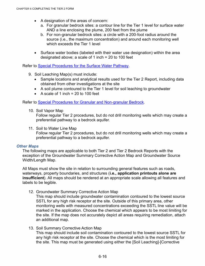
CHAPTER 6 COMPLETING THE TIER 2 FORM
6-16
A designation of the areas of concern: a. For granular bedrock sites: a contour line for the Tier 1 level for surface water
AND a line enclosing the plume, 200 feet from the plume b. For non-granular bedrock sites: a circle with a 200-foot radius around the
source (i.e., the maximum concentration) and around each monitoring well which exceeds the Tier 1 level
Surface water bodies (labeled with their water use designation) within the area designated above; a scale of 1 inch = 20 to 100 feet
Refer to Special Procedures for the Surface Water Pathway.
9. Soil Leaching Map(s) must include:
Sample locations and analytical results used for the Tier 2 Report, including data obtained from other investigations at the site
A soil plume contoured to the Tier 1 level for soil leaching to groundwater
A scale of 1 inch = 20 to 100 feet
Refer to Special Procedures for Granular and Non-granular Bedrock.
10. Soil Vapor Map Follow regular Tier 2 procedures, but do not drill monitoring wells which may create a preferential pathway to a bedrock aquifer.
11. Soil to Water Line Map Follow regular Tier 2 procedures, but do not drill monitoring wells which may create a preferential pathway to a bedrock aquifer.
Other Maps The following maps are applicable to both Tier 2 and Tier 2 Bedrock Reports with the exception of the Groundwater Summary Corrective Action Map and Groundwater Source Width/Length Map.
All Maps must show the site in relation to surrounding general features such as roads, waterways, property boundaries, and structures (i.e., application printouts alone are insufficient). All maps should be rendered at an appropriate scale allowing all features and labels to be legible.
12. Groundwater Summary Corrective Action Map
This map should include groundwater contamination contoured to the lowest source SSTL for any high risk receptor at the site. Outside of this primary area, other monitoring wells with measured concentrations exceeding the SSTL line value will be marked in the application. Choose the chemical which appears to be most limiting for the site. If the map does not accurately depict all areas requiring remediation, attach an additional map.
13. Soil Summary Corrective Action Map This map should include soil contamination contoured to the lowest source SSTL for any high risk receptor at the site. Choose the chemical which is the most limiting for the site. This map must be generated using either the [Soil Leaching]-[Corrective

CHAPTER 6 COMPLETING THE TIER 2 FORM
6-17
Action Map] or [General Contouring]-[Soil], depending on the most restrictive receptor pathway. If the map does not accurately depict all areas requiring remediation, attach an additional map.
14. Monitoring Plan Map Include a map with the monitoring locations clearly marked, including monitoring for groundwater, soil gas, receptor sampling locations, and any new or proposed monitoring points. If monitoring wells are destroyed or no longer accessible, indicate on the map.
15. Landowner Map Provide a scaled (scale 1 inch = 200 to 500 feet) vicinity map showing the site in relation to surrounding general features. It must show, but is not limited to the following pertinent features: roads, waterways, property boundaries, and structures such as schools, hospitals, child care facilities, prisons, and other buildings. Properties which meet the following criteria must be numbered on the Landowner Map and included in the Affected Property Owner Table in the report body: properties within 100 feet of the largest actual plume. If symbols are used for zoning designations, provide a legend which defines the symbols.
16. X, Y Coordinates Map Include a map with the X, Y coordinates, including the (0, 0) location and X, Y coordinates for each receptor, monitoring well, soil gas well, and boring. The map must show the site in relation to surrounding general features such as roads, waterways, property boundaries, and structures. Check the printout of receptor locations with previous maps to be sure they match.
17. Zoning Documentation An additional appendix is required if non-residential zoning is used to derive a target level for a vapor pathway. Documentation in this appendix must include the name, official title, and telephone number of the person(s) contacted to confirm the zoning information. Provide a map showing the zoning and associated boundaries in the area. The zoning map must be legible and rendered at an appropriate scale. If symbols are used for zoning designations on the map, provide a legend which defines the symbols and indicates whether land use is residential or restricted to non-residential. Note: A zoning designation other than residential (e.g., business district, commercial, etc.) does not necessarily preclude residential land use in some cases. It is incumbent on the CGP to verify that no buildings which would qualify as residential (e.g., houses, apartments, nursing homes, schools, child care facilities, prisons, etc.) exist or can be established in areas designated nonresidential.
18. Groundwater Source Width/Length Map Provide the Groundwater Source Width/Length Map(s) generated from the application. If the maximum Sw is from one chemical group and the maximum W is from another, maps for each must be submitted. If site conditions necessitate manual measurement and determination of the greatest measured dimension(s) (e.g. No definitive Flow Direction/groundwater gradient is less than 0.005/RANGE of PLUME/FLOW model parameter set at 150 degrees; Multiple Contour lines) the maps must depict manual measurements. Refer to Tier 2 Software User’s Manual, 7.4 Adjustments to Sw and W Contouring Results.
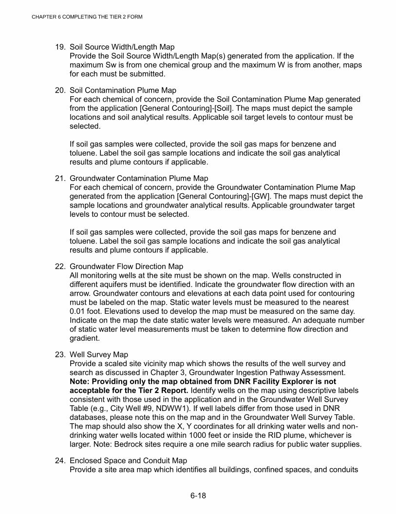
CHAPTER 6 COMPLETING THE TIER 2 FORM
6-18
19. Soil Source Width/Length Map Provide the Soil Source Width/Length Map(s) generated from the application. If the maximum Sw is from one chemical group and the maximum W is from another, maps for each must be submitted.
20. Soil Contamination Plume Map For each chemical of concern, provide the Soil Contamination Plume Map generated from the application [General Contouring]-[Soil]. The maps must depict the sample locations and soil analytical results. Applicable soil target levels to contour must be selected. If soil gas samples were collected, provide the soil gas maps for benzene and toluene. Label the soil gas sample locations and indicate the soil gas analytical results and plume contours if applicable.
21. Groundwater Contamination Plume Map For each chemical of concern, provide the Groundwater Contamination Plume Map generated from the application [General Contouring]-[GW]. The maps must depict the sample locations and groundwater analytical results. Applicable groundwater target levels to contour must be selected. If soil gas samples were collected, provide the soil gas maps for benzene and toluene. Label the soil gas sample locations and indicate the soil gas analytical results and plume contours if applicable.
22. Groundwater Flow Direction Map All monitoring wells at the site must be shown on the map. Wells constructed in different aquifers must be identified. Indicate the groundwater flow direction with an arrow. Groundwater contours and elevations at each data point used for contouring must be labeled on the map. Static water levels must be measured to the nearest 0.01 foot. Elevations used to develop the map must be measured on the same day. Indicate on the map the date static water levels were measured. An adequate number of static water level measurements must be taken to determine flow direction and gradient.
23. Well Survey Map Provide a scaled site vicinity map which shows the results of the well survey and search as discussed in Chapter 3, Groundwater Ingestion Pathway Assessment. Note: Providing only the map obtained from DNR Facility Explorer is not acceptable for the Tier 2 Report. Identify wells on the map using descriptive labels consistent with those used in the application and in the Groundwater Well Survey Table (e.g., City Well #9, NDWW1). If well labels differ from those used in DNR databases, please note this on the map and in the Groundwater Well Survey Table. The map should also show the X, Y coordinates for all drinking water wells and non-drinking water wells located within 1000 feet or inside the RID plume, whichever is larger. Note: Bedrock sites require a one mile search radius for public water supplies.
24. Enclosed Space and Conduit Map Provide a site area map which identifies all buildings, confined spaces, and conduits

CHAPTER 6 COMPLETING THE TIER 2 FORM
6-19
within any receptor ID plume for the vapor pathways. Buildings without basements located within the receptor ID plume and within 200 feet of the actual or modeled plume should be clearly labeled and distinguishable from those buildings with basements. Identify the enclosed space vapor sampling locations and the results of the vapor survey. The location of all water lines within the receptor ID plume for the water line pathways also must be identified. Number all enclosed spaces and conduits on the map to coordinate with "conduit number" from the Enclosed Space/Conduit Survey Table in the Tier 2 report form. Also, use descriptive labels for the receptors consistent with the labels used in the application and narrative portions of the report (e.g., Hwy. 26 sewer main, 209 First Street basement, north property line).
25. Surface Water Map Provide a site map which identifies all surface water bodies within the surface water survey area or applicable receptor ID plume, whichever is larger. If surface water samples were collected for analysis, indicate on the map where the samples were taken. Indicate which areas were visually inspected. Use descriptive labels for the surface water bodies consistent with the labels used in the application and narrative portions of the report (e.g., Skunk River). Ensure the map is appropriately scaled.
Other Appendices 26. Laboratory Data Sheets and Chromatograms.
Provide copies of laboratory data sheets for all samples collected at the site. Provide copies of all chain-of-custody forms and internal laboratory shipment quality checks. Submit chromatograms and associated quantitation reports for waste oil (motor oil), diesel, and gasoline standards used by the laboratory to identify and quantify field samples. The laboratory analytical report for Method OA-2 analysis must state whether the sample tested matches the laboratory standard for waste oil (motor oil), diesel or gasoline or that the sample cannot be reliably matched with any of these standards.
Submit chromatograms for those soil and groundwater samples with maximum concentrations of BTEX and TEH. Chromatograms for all other sample analyses should be obtained from the laboratory and made available to the DNR upon request. Laboratory data sheets which have been previously submitted for the site do not need to be included in this appendix.
27. Construction Diagrams for Soil Gas Monitoring Wells Complete and attach DNR Form 542-1392 for each soil gas monitoring well/point installed to obtain soil gas measurements, including those installed for all previous assessments if not previously submitted. Clearly label on the form that the construction diagram is for a soil gas monitoring well/point. Under "Drilling Method" indicate whether push technology or augering was used to install the vapor monitoring point. If applicable, please include vapor screening results.
28. Boring Logs and Monitoring Well Construction Diagrams. Complete and attach DNR Form 542-1392 for each soil boring/monitoring well placed to investigate the petroleum release at this site, including boring logs and well construction diagrams for any historic investigations if not previously submitted to DNR. Previously submitted documents containing historic logs/borings should be

CHAPTER 6 COMPLETING THE TIER 2 FORM
6-20
referenced on the Appendix 28 cover page.
Indicate the casing and screen material and screen slot size on each diagram. Include the static water level symbol "v" on the diagram for the water level at the time of sampling. At least one static water level measurement must be taken and indicated at the bottom of the log for each boring and well installed at the site.
Each log must include vapor screening results (if applicable) and indicate the interval(s) (*) of soil sample(s) sent for laboratory analysis. All primary and replacement monitoring wells installed must include a soil sample at the elevation of the highest field screening data. Note: some borings may require more than one soil sample. Provide a description of the soil and USCS classification.
29. Drinking and Non-drinking Water Well Logs Provide copies of all available well logs for drinking water wells and non-drinking water wells and copies of DNR Form 542-1226 for wells plugged according to IAC 567-39. Please include both driller’s logs and Iowa Geological Survey Bureau strip logs if available.
30. Off-Site Contamination Source Support Data. Include any necessary documentation as described in Off-site Contamination Source Support Discussion.
31. Tier 1 Selected Information
Pages 5, 6, and 10 of the Tier 1 Report body
Topographic Site Map
Site Plan Map
Field Screening Map
Tank Tightness Test Results
Hydraulic Conductivity Measurements
32. Corrective Action Documentation – optional
Declaration of Environmental Covenants and/or Institutional Controls
Abandoned Water Well Plugging Record(s) DNR Form 542-1226
Iowa DNR Water Supply Notification DNR Form 542-1530
Iowa DNR Water Line - Utility Company Notification DNR Form 542-1531
Iowa DNR Sanitary Sewer Notification. DNR Form 542-1532
Report of Soil Excavation and Associated Documentation
Report of Water Line Removal or Relocation

APPENDICIES

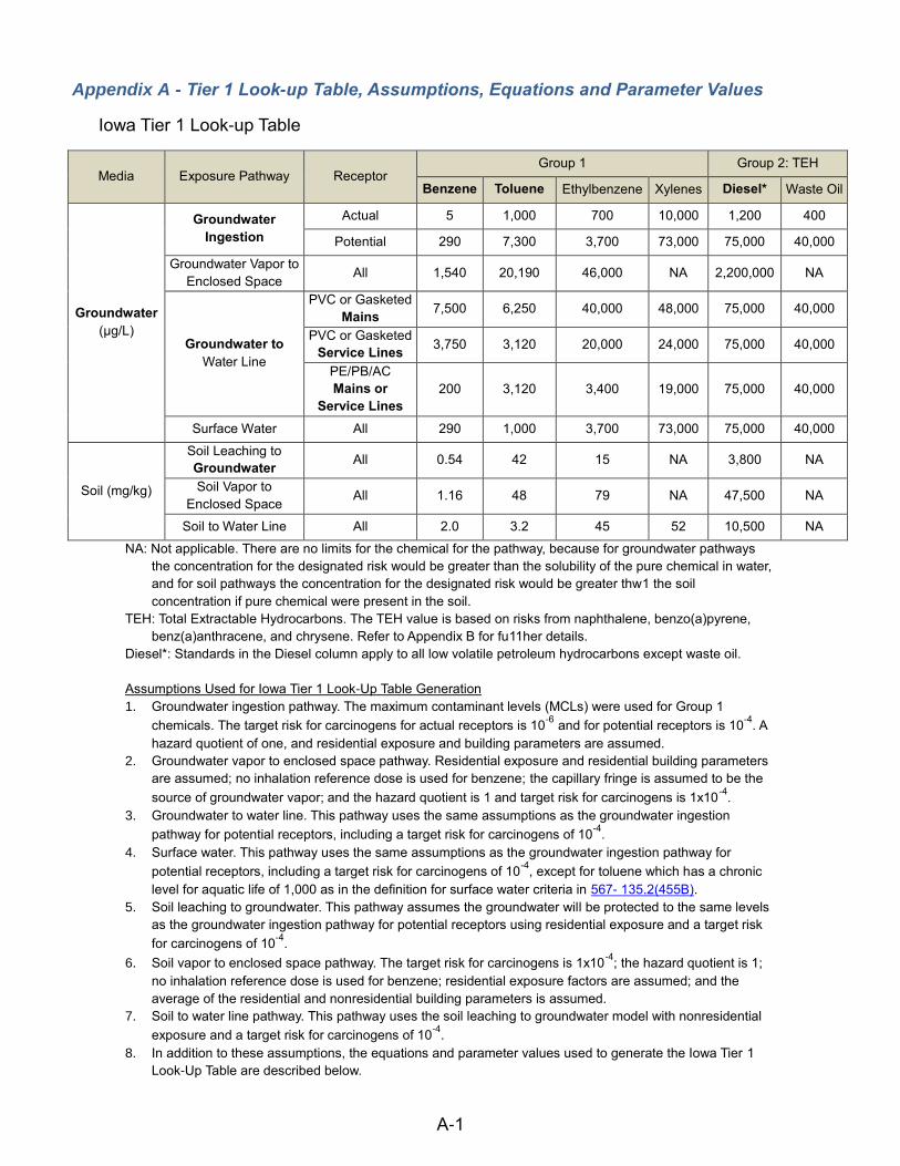
A-1
Appendix A - Tier 1 Look-up Table, Assumptions, Equations and Parameter Values
Iowa Tier 1 Look-up Table
Media Exposure Pathway Receptor Group 1 Group 2: TEH
Benzene Toluene Ethylbenzene Xylenes Diesel* Waste Oil
Groundwater
(µg/L)
Groundwater
Ingestion
Actual 5 1,000 700 10,000 1,200 400
Potential 290 7,300 3,700 73,000 75,000 40,000
Groundwater Vapor to
Enclosed Space All 1,540 20,190 46,000 NA 2,200,000 NA
Groundwater to
Water Line
PVC or Gasketed
Mains 7,500 6,250 40,000 48,000 75,000 40,000
PVC or Gasketed
Service Lines 3,750 3,120 20,000 24,000 75,000 40,000
PE/PB/AC
Mains or
Service Lines
200 3,120 3,400 19,000 75,000 40,000
Surface Water All 290 1,000 3,700 73,000 75,000 40,000
Soil (mg/kg)
Soil Leaching to
Groundwater All 0.54 42 15 NA 3,800 NA
Soil Vapor to
Enclosed Space All 1.16 48 79 NA 47,500 NA
Soil to Water Line All 2.0 3.2 45 52 10,500 NA
NA: Not applicable. There are no limits for the chemical for the pathway, because for groundwater pathways
the concentration for the designated risk would be greater than the solubility of the pure chemical in water,
and for soil pathways the concentration for the designated risk would be greater thw1 the soil
concentration if pure chemical were present in the soil.
TEH: Total Extractable Hydrocarbons. The TEH value is based on risks from naphthalene, benzo(a)pyrene,
benz(a)anthracene, and chrysene. Refer to Appendix B for fu11her details.
Diesel*: Standards in the Diesel column apply to all low volatile petroleum hydrocarbons except waste oil.
Assumptions Used for Iowa Tier 1 Look-Up Table Generation
1. Groundwater ingestion pathway. The maximum contaminant levels (MCLs) were used for Group 1
chemicals. The target risk for carcinogens for actual receptors is 10-6
and for potential receptors is 10-4
. A
hazard quotient of one, and residential exposure and building parameters are assumed.
2. Groundwater vapor to enclosed space pathway. Residential exposure and residential building parameters
are assumed; no inhalation reference dose is used for benzene; the capillary fringe is assumed to be the
source of groundwater vapor; and the hazard quotient is 1 and target risk for carcinogens is 1x10⁻⁴
.
3. Groundwater to water line. This pathway uses the same assumptions as the groundwater ingestion
pathway for potential receptors, including a target risk for carcinogens of 10-4
.
4. Surface water. This pathway uses the same assumptions as the groundwater ingestion pathway for
potential receptors, including a target risk for carcinogens of 10-4
, except for toluene which has a chronic
level for aquatic life of 1,000 as in the definition for surface water criteria in 567- 135.2(455B).
5. Soil leaching to groundwater. This pathway assumes the groundwater will be protected to the same levels
as the groundwater ingestion pathway for potential receptors using residential exposure and a target risk
for carcinogens of 10-4
.
6. Soil vapor to enclosed space pathway. The target risk for carcinogens is 1x10⁻⁴
; the hazard quotient is 1;
no inhalation reference dose is used for benzene; residential exposure factors are assumed; and the
average of the residential and nonresidential building parameters is assumed.
7. Soil to water line pathway. This pathway uses the soil leaching to groundwater model with nonresidential
exposure and a target risk for carcinogens of 10-4
.
8. In addition to these assumptions, the equations and parameter values used to generate the Iowa Tier 1
Look-Up Table are described below.

Appendix A - Tier 1 Look-up Table, Assumptions, Equations and Parameter Values
A-2
Groundwater Ingestion Equations Carcinogens:
𝑅𝐵𝑆𝐿𝑤 [𝑚𝑔
𝐿 − 𝐻2𝑂] =
𝑇𝑅 × 𝐵𝑊 × 𝐴𝑇𝑐 × (365𝑑𝑎𝑦𝑠𝑦𝑒𝑎𝑟
)
𝑆𝐹𝑜 × 𝐼𝑅𝑤 × 𝐸𝐹 × 𝐸𝐷
Non-carcinogens:
𝑅𝐵𝑆𝐿𝑤 [𝑚𝑔
𝐿 − 𝐻2𝑂] =
𝑇𝐻𝑄 × 𝑅𝑓𝐷𝑜 × 𝐴𝑇𝑐 × (365𝑑𝑎𝑦𝑠𝑦𝑒𝑎𝑟
)
𝐼𝑅𝑤 × 𝐸𝐹 × 𝐸𝐷
Soil Leaching to Groundwater Equations
𝑅𝐵𝑆𝐿𝑠𝑙 [𝑚𝑔
𝑘𝑔 − 𝑠𝑜𝑖𝑙] =
𝑅𝐵𝑆𝐿𝑤 [𝑚𝑔
𝐿 − 𝐻2𝑂]
𝐿𝐹
𝐿𝐹 [𝑚𝑔 𝐿⁄ − 𝐻2𝑂
𝑚𝑔 𝑘𝑔⁄ − 𝑠𝑜𝑖𝑙] =
𝜌𝑠
𝜃𝑤𝑠 + 𝑘𝑠𝜌𝑠 +𝐻𝜃𝑎𝑠 (1 +𝑈𝛿𝐼𝑊)
Soil Vapor to Enclosed Space Equations
𝑅𝐵𝑆𝐿𝑠𝑣 [𝑚𝑔
𝑘𝑔 − 𝑠𝑜𝑖𝑙] = (
𝑅𝐵𝑆𝐿𝑎𝑖𝑟 [𝜇𝑔
𝑚3 − 𝑎𝑖𝑟]
𝑉𝐹𝑠𝑣)(
𝑚𝑔
1000𝜇𝑔)
𝑉𝑊𝑠𝑣 [𝑚𝑔 𝑚3 − 𝑎𝑖𝑟⁄
𝑚𝑔 𝑘𝑔 − 𝑠𝑜𝑖𝑙⁄] =
(
𝐻𝜌𝑆
𝜃𝑊𝑆 + 𝑘𝑠𝜌𝑠 + 𝐻𝜃𝑎𝑠 [𝐷𝑆𝑒𝑓𝑓 𝐿𝑠⁄𝐸𝑅𝐿𝐵
]
1 + [𝐷𝑠𝑒𝑓𝑓 𝐿𝑠⁄𝐸𝑅𝐿𝐵
] + [𝐷𝑠𝑒𝑓𝑓 𝐿𝑠⁄
(𝐷𝑐𝑟𝑎𝑐𝑘𝑒𝑓𝑓 𝐿𝑐𝑟𝑎𝑐𝑘⁄ )
𝜂]
)
103𝑐𝑚3 − 𝑘𝑔
𝑚3 − 𝑔
𝐷𝑐𝑟𝑎𝑐𝑘𝑒𝑓𝑓 [
𝑐𝑚2
𝑠] = 𝐷𝑎𝑖𝑟 (
θ𝑎𝑐𝑟𝑎𝑐𝑘3.33
𝜃𝑇2 ) + 𝐷𝑤𝑎𝑡 (
1
𝐻)(θ𝑎𝑐𝑟𝑎𝑐𝑘
3.33
𝜃𝑇2 )
𝐷𝑠𝑒𝑓𝑓 [
𝑐𝑚2
𝑠] = 𝐷𝑎𝑖𝑟 (
θ𝑎𝑠3.33
𝜃𝑇2 ) + 𝐷𝑤𝑎𝑡 (
1
𝐻)(θ𝑎𝑐𝑟𝑎𝑐𝑘
3.33
𝜃𝑇2 )
Indoor Air Inhalation Equations Carcinogens:
𝑅𝐵𝑆𝐿𝑎𝑖𝑟 [𝜇𝑔
𝑚3 − 𝑎𝑖𝑟] =
𝑇𝑅 × 𝐵𝑊 × 𝐴𝑇𝑐 × (365𝑑𝑎𝑦𝑠𝑦𝑒𝑎𝑟 ) × (
1000𝜇𝑔𝑚𝑔 )
𝐼𝑅𝑎𝑖𝑟 × 𝐸𝐹 × 𝐸𝐷

Appendix A - Tier 1 Look-up Table, Assumptions, Equations and Parameter Values
A-3
Noncarcinogens:
𝑅𝐵𝑆𝐿𝑎𝑖𝑟 [𝜇𝑔
𝑚3 − 𝑎𝑖𝑟] =
𝑇𝐻𝑄 × 𝑅𝑓𝐷𝑖 × 𝐵𝑊 × 𝐴𝑇𝑛 × (365𝑑𝑎𝑦𝑠𝑦𝑒𝑎𝑟
) × (1000𝜇𝑔𝑚𝑔
)
𝐼𝑅𝑎𝑖𝑟 × 𝐸𝐹 × 𝐸𝐷
Groundwater Vapor to Enclosed Space Equations
𝑅𝐵𝑆𝐿𝑔𝑤 [𝑚𝑔
𝐿 − 𝐻2𝑂] = (
𝑅𝐵𝑆𝐿𝑎𝑖𝑟 [𝜇𝑔
𝑚3 − 𝑎𝑖𝑟]
𝑉𝐹𝑔𝑤)(
𝑚𝑔
1000𝜇𝑔)
𝑉𝑊𝑔𝑤 [𝑚𝑔 𝑚3 − 𝑎𝑖𝑟⁄
𝑚𝑔 𝐿 − 𝐻2𝑂⁄] =
𝐻 [𝐷𝑠𝑒𝑓𝑓 𝐿𝑔𝑤⁄𝐸𝑅𝐿𝐵
]
1 + [𝐷𝑠𝑒𝑓𝑓 𝐿𝑔𝑤⁄𝐸𝑅𝐿𝐵
] + [𝐷𝑠𝑒𝑓𝑓 𝐿𝑔𝑤⁄
(𝐷𝑐𝑟𝑎𝑐𝑘𝑒𝑓𝑓 𝐿𝑐𝑟𝑎𝑐𝑘⁄ )
𝜂]
(103𝐿
𝑚3)
Variable Definitions
δ groundwater mixing zone thickness (cm)
η areal fraction of cracks in foundation/wall (cm2-cracks/cm
2-area)
ρs soil bulk density (g/cm3)
ϴacrack volumetric air content in foundation/wall cracks (cm3-air/cm
3-soil)
ϴas volumetric air content in vadose zone (cm3-air/cm
3-soil)
ϴT total soil porosity (cm3-voids/cm
3-soil)
ϴwcrack volumetric water content in foundation/wall cracks (cm3-H2O/cm
3-soil)
ϴws volumetric water content in vadose zone (cm3-H2O/cm
3-soil)
ATc averaging time for carcinogens (years)
ATn averaging time for non-carcinogens (years)
BW body weight (kg)
Dair
chemical diffusion coefficient in air (cm2/s)
Dwat
chemical diffusion coefficient in water (cm2/s)
D eff crack effective diffusion coefficient through foundation cracks (cm
2/s)
D eff s effective diffusion coefficient in soil based on vapor-phase concentration (cm
2/s)
ED exposure duration (years)
EF exposure frequency (days/year)
ER enclosed space air exchange rate (s-1
)
foc fraction organic carbon in the soil (kg-C/kg-soil)
H henry’s law constant (L-H2O)/L-air)
i groundwater head gradient (cm/cm)
I infiltration rate of water through soil (cm/year)
IRair daily indoor inhalation rate (m3/day)
IRw daily water ingestion rate (L/day)
K hydraulic conductivity (cm/year)
Koc carbon-water sorption coefficient (L-H2O/kg-C)
ks soil-water sorption coefficient (L-H2O/kg-soil), foc x Koc

Appendix A - Tier 1 Look-up Table, Assumptions, Equations and Parameter Values
A-4
LB enclosed space volume/infiltration area ratio (cm)
Lcrack enclosed space foundation or wall thickness (cm)
LF leaching factor from soil to groundwater ((mg/L-H2O)/(mg/kg-soil))
Lgw depth to groundwater from the enclosed space foundation (cm)
Ls depth to subsurface soil sources from the enclosed space foundation (cm)
RBSLair Risk-Based Screening Level for indoor air (µg/m3-air)
RBSLgw Risk-Based Screening Level for vapor from groundwater to enclosed space air inhalation (mg/L-H2O)
RBSLsl Risk-Based Screening Level for soil leaching to groundwater (mg/kg-soil)
RBSLsv Risk-Based Screening Level for vapors from soil to enclosed space air inhalation (mg/kg-soil)
RBSLw Risk-Based Screening Level for groundwater ingestion (mg/L-H2O)
RfDi inhalation chronic reference dose (mg/(kg-day))
RfDo oral chronic reference dose (mg/(kg-day))
SFi inhalation cancer slope factor ((kg-day)/mg)
SFo oral cancer slope factor ((kg-day)/mg)
THQ target hazard quotient for individual constituents (unitless)
TR target excess individual lifetime cancer risk (unitless)
U groundwater Darcy velocity (cm/year), U=Ki
VFgw volatilization factor for vapors from groundwater to enclosed space ((mg/m3-air)/(mg/kg-soil))
VFsv volatilization factor for vapors from soil to enclosed space ((mg/m3-air)/(mg/kg-soil))
W width of soil source area parallel to groundwater flow direction (cm)
Soil and Groundwater Parameter Values Used for Iowa Tier 1 Table Generation
Parameter Iowa Tier 1 Table Value
K hydraulic conductivity 16060 cm/year
i groundwater head gradient 0.01 cm/cm
W width of soil source area parallel to groundwater flow direction 1500 cm
l infiltration rate of water through soil 7 cm/year
δ groundwater mixing zone thickness 200 cm
ρs soil bulk density 1.86 g/cm3
ϴas volumetric air content in vadose zone 0.2 cm3-air/cm
3-soil
ϴws volumetric water content in vadose zone 0.1 cm3-H2O/cm
3-soil
ϴacrack volumetric air content in foundation/wall cracks 0.2 cm3-air/cm
3-soil
ϴwcrack volumetric water content in foundation/wall cracks 0.1 cm3-H2O/cm
3-soil
ϴT total soil porosity 0.3 cm3-voids/cm
3-soil
foc fraction organic carbon in the soil 0.01 kg-C/kg-soil
Ls depth to subsurface soil sources from the enclosed space foundation 1 cm
Lgw depth to groundwater from the enclosed space foundation 1 cm
Exposure Factors Used in Iowa Tier 1 Table Generation
Parameter Residential Nonresidential
ATc (years) averaging time for carcinogens 70 70
ATn (years) averaging time for non-carcinogens 30 25
BW (kg) body weight 70 70

Appendix A - Tier 1 Look-up Table, Assumptions, Equations and Parameter Values
A-5
ED (years) exposure duration 30 25
EF (days/years) exposure frequency 350 250
IRair (m3/day) daily indoor inhalation rate 15 20
IRw (L/day) daily water ingestion rate 2 1
THQ (unitless) target hazard quotient for individual constituents 1.0 1.0
Building Parameters Used in Iowa Tier 1 Table Generation
Parameter Residential Nonresidential
ER (s-1
) enclosed space air exchange rate 0.00014 0.00023
LB (cm) enclosed space volume/infiltration area ratio 200 300
Lcrack (cm) enclosed space foundation or wall thickness 15 15
η areal fraction of cracks in foundation/wall 0.01 0.01
Chemical-Specific Parameter Values Used for Iowa Tier 1 Table Generation
Chemical Dair
(cm2/s) D
wat (cm
2/s) H (L-air/L-water) log(Koc), L/kg
Benzene 0.093 1.1e-5 0.22 1.58
Toluene 0.085 9.4e-6 0.26 2.13
Ethylbenzene 0.076 8.5e-6 0.32 1.98
Xylenes 0.072 8.5e-6 0.29 2.38
Naphthalene 0.072 9.4e-6 0.049 3.11
Benzo(a)pyrene 0.050 5.8e-6 5.8e-8 5.59
Benz(a)anthracene 0.05 9.0e-6 5.74e-7 6.14
Chrysene 0.025 6.2e-6 4.9e-7 5.30
Saturation Values Used to Determine "NA" for the Iowa Tier 1 Table
Chemical Solubility in Water (mg/L)
S Saturation in Soil (mg/kg)
Cssat
Benzene 1,750 801
Toluene 535 765
Ethylbenzene 152 159
Xylenes 198 492
Naphthalene 31 401
Benzo(a)pyrene 0.0012 4.69
Benz(a)anthracene 0.014 193.3
Chrysene 0.0028 5.59
The maximum solubility of the pure chemical in water is listed in the table above. The equation below is used to calculate the soil concentration (Cs
sat) at which dissolved pore-water and vapor phases become saturated. Tier 1
default values are used in the equation. “NA” (for not applicable) is used in the Tier 1 table when the risk-based value exceeds maximum solubility for water (S) or maximum saturation for soil (Cs
sat).
𝐶𝑠𝑠𝑎𝑡 [
𝑚𝑔
𝑘𝑔 − 𝑠𝑜𝑖𝑙] = (
𝑆
𝜌𝑠) × (𝐻𝜃𝑎𝑠 + 𝜃𝑤𝑠 + 𝑘𝑠𝜌𝑠)

Appendix A - Tier 1 Look-up Table, Assumptions, Equations and Parameter Values
A-6
Slope Factors and Reference Doses Used for Iowa Tier 1 Table Generation
Chemical SFi ((kg-day)/mg) SFo ((kg-day/mg) RfDi (mg/(kg-day)) RfDo (mg/kg-day))
Benzene 0.029 0.029 --- ---
Toluene --- --- 0.114 0.2
Ethylbenzene --- --- 0.286 0.1
Xylenes --- --- 2.0 2.0
Naphthalene --- --- 0.004 0.004
Benzo(a)pyrene 6.1 7.3 --- ---
Benz(a)anthracene 0.61 0.73 --- ---
Chrysene 0.061 0.073 --- ---
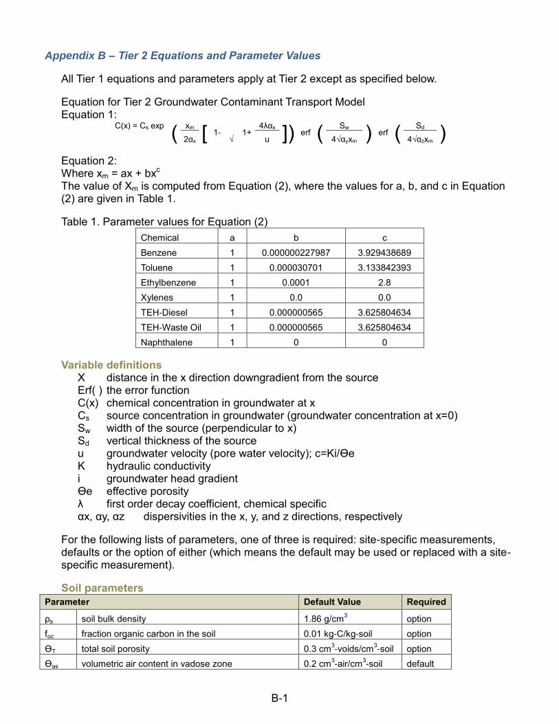
B-1
Appendix B – Tier 2 Equations and Parameter Values
All Tier 1 equations and parameters apply at Tier 2 except as specified below.
Equation for Tier 2 Groundwater Contaminant Transport Model Equation 1:
C(x) = Cs exp
( xm
[ 1- √
1+ 4λαx
]) erf ( Sw
) erf ( Sd
) 2αx u 4√αyxm 4√αzxm
Equation 2: Where xm = ax + bxc The value of Xm is computed from Equation (2), where the values for a, b, and c in Equation (2) are given in Table 1.
Table 1. Parameter values for Equation (2)
Chemical a b c
Benzene 1 0.000000227987 3.929438689
Toluene 1 0.000030701 3.133842393
Ethylbenzene 1 0.0001 2.8
Xylenes 1 0.0 0.0
TEH-Diesel 1 0.000000565 3.625804634
TEH-Waste Oil 1 0.000000565 3.625804634
Naphthalene 1 0 0
Variable definitions X distance in the x direction downgradient from the source Erf( ) the error function C(x) chemical concentration in groundwater at x Cs source concentration in groundwater (groundwater concentration at x=0) Sw width of the source (perpendicular to x) Sd vertical thickness of the source u groundwater velocity (pore water velocity); c=Ki/ϴe K hydraulic conductivity i groundwater head gradient ϴe effective porosity λ first order decay coefficient, chemical specific αx, αy, αz dispersivities in the x, y, and z directions, respectively
For the following lists of parameters, one of three is required: site-specific measurements, defaults or the option of either (which means the default may be used or replaced with a site-specific measurement).
Soil parameters
Parameter Default Value Required
ρs soil bulk density 1.86 g/cm3 option
foc fraction organic carbon in the soil 0.01 kg-C/kg-soil option
ϴT total soil porosity 0.3 cm3-voids/cm
3-soil option
ϴas volumetric air content in vadose zone 0.2 cm3-air/cm
3-soil default

Appendix B – Tier 2 Equations and Parameter Values
B-2
ϴws volumetric water content in vadose zone 0.1 cm3-H2O/cm
3-soil default
ϴacrack volumetric air content in foundation/wall cracks 0.2 cm3-air/cm
3-soil default
ϴwcrack volumetric water content in foundation/wall cracks 0.1 cm3-H2O/cm
3-soil default
l infiltration rate of water through soil 7 cm/year default
If the total porosity is measured, assume 1/3 is air filled and 2/3 is water filled for determining the water and air fraction in the vadose zone soil and floor cracks.
Groundwater Transport Modeling Parameters
Parameter Default Value Required
K hydraulic conductivity 16060 cm/year site-specific
i groundwater head gradient 0.01 cm/cm site-specific
Sw width of the source use procedure specified in 135.10(2) site-specific
Sd vertical thickness of the source 3 m default
αx dispersivity in the x direction 0.1 x default
αy dispersivity in the y direction 0.33 αx default
αz dispersivity in the z direction 0.05 αx default
ϴe effective porosity 0.1 default
Where u=Ki/ϴe
First-order Decay Coefficients
Chemical Default Value λ
(d-1) Required
Benzene 0.000127441 default
Toluene 0.0000208066 default
Ethylbenzene 0.0 default
Xylenes 0.0005 default
Naphthalene 0.00013 default
TEH-Diesel 0.0000554955 default
TEH-Waste Oil 0.0000554955 default
Other Parameters for Groundwater Vapor to Enclosed Space
Parameter Default Value Required
Lgw depth to groundwater from the enclosed space foundation 1 cm option
LB enclosed space volume/infiltration area ratio 200 cm option
ER (s-1) enclosed space air exchange rate 0.00014 default
Lcrack enclosed space foundation or wall thickness 15 cm default
η areal fraction of cracks in foundation/wall 0.01 default

Appendix B – Tier 2 Equations and Parameter Values
B-3
Other Parameters for Soil Vapor to Enclosed Space
Parameter Default Value Required
Ls depth to subsurface soil sources from the enclosed space foundation 1 cm option
LB enclosed space volume/infiltration area ratio 200 cm* option
ER (s-1) enclosed space air exchange rate 0.000185* default
Lcrack enclosed space foundation or wall thickness 15 cm default
η areal fraction of cracks in foundation/wall 0.01 default
*These values are an average of residential and nonresidential factors.
Soil Leaching to Groundwater
Parameter Default Value Required
δ groundwater mixing zone 2 m default
Building Parameters for Iowa Tier 2
Parameter Residential Nonresidential
ER (s-1) enclosed space air exchange rate 0.00014 0.00023
LB enclosed space volume/infiltration area ratio 200 cm 300 cm
Other Parameters For Tier 2, the following are the same as Tier 1 values (refer to Appendix A): chemical-specific parameters, slope factors and reference doses, and exposure factors (except for those listed below).
Exposure Factors for Tier 2 Groundwater Vapor to Enclosed Space Modeling:
Potential Residential: use residential exposure and residential building parameters.
Potential Nonresidential: use nonresidential exposure and nonresidential building parameters.
Diesel and Waste Oil
Diesel and Waste Oil Chemical-Specific Values for Tier 1
Media Exposure Pathway
Receptor Naphthalene Benzo(a)pyrene Benz(a)anthracene Chrysene
Groundwater (µg/L)
Groundwater Ingestion
actual 150 0.012 0.12 1.2
potential 150 1.2 12.0 NA
Groundwater Vapor to Enclosed Space
all 4,440 NA NA NA
Groundwater to Water Line
all 150 1.2 12.0 NA
Surface Water all 150 1.2 12.0 NA
Soil (mg/kg)
Soil Leaching to Groundwater
all 7.6 NA NA NA
Soil Vapor to Enclosed Space
all 95 NA NA NA
Soil to Water Line all 21 NA NA NA
Due to the difficulties with analytical methods for the four individual chemicals listed in the above table, Total Extractable Hydrocarbon (TEH) default values were calculated for each chemical, using the assumption that diesel contains 0.2% naphthalene, 0.001%

Appendix B – Tier 2 Equations and Parameter Values
B-4
benzo(a)pyrene, 0.001% benz(a)anthracene, and 0.001% chrysene. Resulting TEH Default Values are shown in the following table.
Diesel TEH Default Values
Media Exposure Pathway Receptor Naphthalene Benzo(a)pyrene Benz(a)anthracene Chrysene
Groundwater (µg/L)
Groundwater Ingestion actual 75,000 1,200 12,0000 120,000
potential 75,000 120,000 1,200,000 NA
Groundwater Vapor to Enclosed Space
all 2,200,000 NA NA NA
Groundwater to Water Line
all 75,000 120,000 1,200,000 NA
Surface Water all 75,000 120,000 1,200,000 NA
Soil (mg/kg)
Soil Leaching to Groundwater
all 3,800 NA NA NA
Soil Vapor to Enclosed Space
all 47,500 NA NA NA
Soil to Water Line all 10,500 NA NA NA
The lowest TEH default value for each pathway (shown as a shaded box) was used in the Tier 1 Table.
Due to the difficulties with analytical methods for the four individual chemicals, Total Extractable Hydrocarbon (TEH) default values were calculated for each chemical, using the assumption that waste oil contains no naphthalene, 0.003% benzo(a)pyrene, 0.003% benz(a)anthracene, and 0.003% chrysene.
Resulting TEH Default Values are shown in the following table.
Waste Oil TEH Default Values
Media Exposure Pathway Receptor Naphthalene Benzo(a)pyrene Benz(a)anthracene Chrysene
Groundwater (µg/L)
Groundwater Ingestion actual NA 400 4,000 40,000
potential NA 40,000 40,000 NA
Groundwater Vapor to Enclosed Space
all NA NA NA NA
Groundwater to Water Line
all NA 40,000 400,000 NA
Surface Water all NA 40,000 400,000 NA
Soil (mg/kg)
Soil Leaching to Groundwater
all NA NA NA NA
Soil Vapor to Enclosed Space
all NA NA NA NA
Soil to Water Line all NA NA NA NA
The lowest TEH default value for each pathway (shown as a shaded box) was used in the Tier 1 Table.

C-1
Appendix C – Declaration of Restrictive Covenants Rescinded IAB 7/19/06, effective 8/23/06

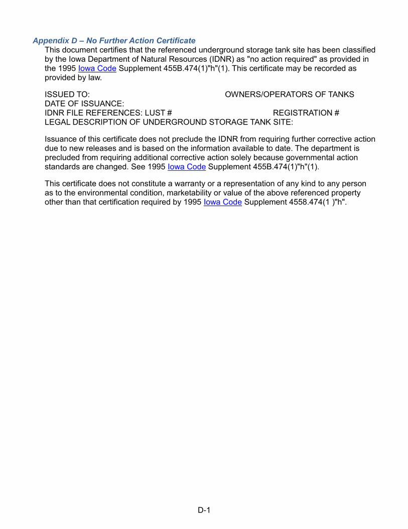
D-1
Appendix D – No Further Action Certificate This document certifies that the referenced underground storage tank site has been classified by the Iowa Department of Natural Resources (IDNR) as "no action required" as provided in the 1995 Iowa Code Supplement 455B.474(1)"h"(1). This certificate may be recorded as provided by law.
ISSUED TO: OWNERS/OPERATORS OF TANKS DATE OF ISSUANCE: IDNR FILE REFERENCES: LUST # REGISTRATION # LEGAL DESCRIPTION OF UNDERGROUND STORAGE TANK SITE:
Issuance of this certificate does not preclude the IDNR from requiring further corrective action due to new releases and is based on the information available to date. The department is precluded from requiring additional corrective action solely because governmental action standards are changed. See 1995 Iowa Code Supplement 455B.474(1)"h"(1).
This certificate does not constitute a warranty or a representation of any kind to any person as to the environmental condition, marketability or value of the above referenced property other than that certification required by 1995 Iowa Code Supplement 4558.474(1 )"h".


E-1
Appendix E – Field Office Contact Information The Field Services and Compliance Bureau includes six field offices throughout the state. Field Office Staff conduct routine inspections of all facilities permitted by the Environmental Services Division, including Leaking Underground Storage Tank sites. Additionally, Field Office Staff responds to spills, address public complaints, assist in dispute resolution, and work with other local and state and federal agencies to educate the public and regulated community and protect Iowa's nature resources.
Field Office 1 909 W Main St Manchester 52057 (563) 927-2640
Field Office 2 2300 15
th St SW
Mason City 50401 (641) 424-4073
Field Office 3 1900 N. Grand Spencer 51303 (712) 262-4177
Field Office 4 1401 Sunnyside Ln Atlantic 50022 (712)243-1934
Field Office 5 401 SW 7
th Ste M
Des Moines 50309 (515) 281-9069
Field Office 6 1004 W Madison Washington 52353 (319) 653-2135
Allamakee Benton Blackhawk Bremer Buchanan Chickasaw Clayton Delaware Dubuque Fayette Howard Iowa Jackson Jones Linn Winneshiek
Butler Cerro Gordo Floyd Franklin Grundy Hamilton Hancock Hardin Humboldt Kossuth Mitchell Webster Winnebago Worth Wright
Buena Vista Calhoun Cherokee Clay Dickinson Emmet Ida Lyon O’Brien Osceola Palo Alto Plymouth Pocahontas Sac Sioux Woodbury
Adair Adams Audubon Carroll Cass Crawford Fremont Green Guthrie Harrison Mills Monona Montgomery Page Pottawattamie Ringgold Shelby Taylor Union
Appanoose Boone Clarke Dallas Decatur Jasper Lucas Madison Mahaska Marion Marshall Monroe Polk Poweshiek Story Tama Warren Wayne
Cedar Clinton Davis Des Moines Henry Iowa Jefferson Johnson Keokuk Lee Louisa Muscatine Scott Van Buren Wapello Washington


F-1
Appendix F – Bedrock Less Than 50 Feet Deep

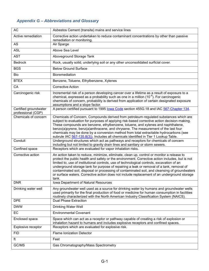
G-1
Appendix G – Abbreviations and Glossary
AC Asbestos Cement (transite) mains and service lines
Active remediation Corrective action undertaken to reduce contaminant concentrations by other than passive remediation or monitoring.
AS Air Sparge
ASL Above Sea Level
AST Aboveground Storage Tank
Bedrock Rock, usually solid, underlying soil or any other unconsolidated surficial cover.
BGS Below Ground Surface
Bio Bioremediation
BTEX Benzene, Toluene, Ethylbenzene, Xylenes
CA Corrective Action
Carcinogenic risk Incremental risk of a person developing cancer over a lifetime as a result of exposure to a chemical, expressed as a probability such as one in a million (10
-6). For carcinogenic
chemicals of concern, probability is derived from application of certain designated exposure assumptions and a slope factor.
Certified groundwater professional (CGP)
A person certified pursuant to 1995 Iowa Code section 455G.18 and IAC 567-Chapter 134.
Chemicals of concern Chemicals of Concern, Compounds derived from petroleum-regulated substances which are subject to evaluation for purposes of applying risk-based corrective action decision-making. These compounds are benzene, ethylbenzene, toluene, and xylenes and naphthalene, benzo(a)pyrene, benz(a)anthracene, and chrysene. The measurement of the last four chemicals may be done by a conversion method from total extractable hydrocarbons (see subrule IAC 567-135.8(3)). Includes all chemicals identified in Tier 1 Lookup Table.
Conduit Underground structures which act as pathways and receptors for chemicals of concern including but not limited to gravity drain lines and sanitary or storm sewers.
Confined space Receptors which are evaluated for vapor inhalation risks.
Corrective action An action taken to reduce, minimize, eliminate, clean up, control or monitor a release to protect the public health and safety or the environment. Corrective action includes, but is not limited to, use of institutional controls, use of technological controls, excavation of an underground storage tank for purpose of repairing a leak or removal of a tank, removal of contaminated soil, disposal or processing of contaminated soil, and cleansing of groundwaters or surface waters. Corrective action does not include replacement of an underground storage tank.
DNR Iowa Department of Natural Resources
Drinking water well Any groundwater well used as a source for drinking water by humans and groundwater wells used primarily for the final production of food or medicine for human consumption in facilities routinely characterized with the North American Industry Classification System (NAICS).
DPE Dual Phase Extraction
DWW Drinking Water Well
EC Environmental Covenant
Enclosed space Space which can act as a receptor or pathway capable of creating a risk of explosion or inhalation hazard to humans and includes explosive receptors and confined spaces.
Explosive receptor Receptors which are evaluated for explosive risk.
FID Flame Ionization Detector
ft Feet
GC/MS Gas Chromatography/Mass Spectrometry

Appendix G – Abbreviations and Glossary
G-2
Groundwater ingestion pathway
Pathway through groundwater by which chemicals of concern may result in exposure to a human.
Groundwater plume The extent of groundwater impacted by the release of chemicals of concern.
Groundwater to water line pathway
Pathway through groundwater which leads to a water line.
Groundwater vapor to enclosed space pathway
Pathway through groundwater by which vapors from chemicals of concern may lead to a receptor creating an inhalation or explosive risk hazard.
GW Groundwater
GWI Groundwater Ingestion
HR High Risk
HVE High Vacuum Extraction
IAC Iowa Administrative Code
ISCO In Situ Chemical Oxidation
K Hydraulic Conductivity
LEL Lower Explosive Limit
LIF Laser Induced Fluorescence
LR Low Risk
LUST Leaking Underground Storage Tank
m/d meters/day
MCL Maximum Contaminant Level
mg/L milligrams per liter
MPE Multi Phase Extraction
MtBE Methyl-tertiary Butyl Ether
MW Monitoring Well
NAR No Action Required
ND Non-Detectable, or Non-Detect
NFA No Further Action
Non-drinking water well
Any groundwater well (except an extraction well used as part of a remediation system) not defined as a drinking water well including a groundwater well which is not properly plugged in accordance with DNR rules in IAC 567 -Chapters 39 and 49.
Nonresidential area Land which is not currently used as a residential area and which is zoned for nonresidential uses.
OE Overexcavation
O/O Owner/Operator
OA1 Group 1 chemicals benzene, toluene, ethylbenzene, and xylene (BTEX)
OA2 Group 2 chemicals total extractable hydrocarbons diesel (TEH-d) and waste oil (TEH-wo)
OE Over-excavation or excavation
Pathway A transport mechanism by which chemicals of concern may reach a receptor(s) or the location(s) of a potential receptor.
P&T Pump and Treat
PB Polybutylene
PE Polyethylene

Appendix G – Abbreviations and Glossary
G-3
PGWS Protected Groundwater Source
PID Photoionization detector
Point of compliance Location(s) at the source(s) of contamination or at the location(s) between the source(s) and the point(s) of exposure where concentrations of chemicals of concern must meet applicable risk-based screening levels at Tier 1 or other target level(s) at Tier 2 or Tier 3.
Point of exposure Location(s) at which an actual or potential receptor may be exposed to chemicals of concern via a pathway.
Potential receptor Receptor not in existence at the time a Tier 1, Tier 2 or Tier 3 site assessment is prepared, but which could reasonably be expected to exist within 20 years of the preparation of the Tier 1, Tier 2, or Tier 3 site assessment.
ppb parts per billion
ppm parts per million
Preferential pathway Conditions which act as a pathway permitting contamination to migrate through soils and to groundwater at a faster rate than would be expected through naturally occurring undisturbed soils or unfractured bedrock including but not limited to wells, cisterns, tile lines, drainage systems, utility lines and envelopes, and conduits.
Protected groundwater source
Saturated bed, formation, or group of formations which has a hydraulic conductivity of at least 0.44 meters per day (m/d) and a total dissolved solids of less than 2,500 milligrams per liter (mg/I) and a bedrock aquifer with total dissolved solids of less than 2,500 milligrams per liter (mg/I) if bedrock is encountered before groundwater.
PVC Polyvinyl Chloride
PWS Public Water Supply
RBCA Risk-Based Corrective Action
Receptor Enclosed spaces, conduits, protected groundwater sources, drinking and non-drinking water wells, surface water bodies, and public water systems which when impacted by chemicals of concern may result in exposure to humans and aquatic life, explosive conditions or other adverse effects on health, safety and the environment.
Receptor identification plume (receptor ID plume)
Plume which identifies all receptors which must be evaluated for a receptor type. The receptor ID plume is generated using Tier 2 application.
Receptor type Category of a pathway based on receptor conditions that will determine the target level at the point of exposure.
Residential area Land used as a permanent residence or domicile, such as a house, apartment, nursing home, school, child care facility or prison, land zoned for such uses, or land where no zoning is in place.
Risk-based screening level (RBSL)
Risk-based concentration level for chemicals of concern developed for a Tier 1 analysis to be met at the point(s) of compliance and incorporated in the Tier 1 Look-up Table.
RP Responsible Party
SCR Site Cleanup Report
SG Soil Gas
SHL State Hygienic Laboratory
Site cleanup report Report required to be submitted by these rules and in accordance with DNR guidance which may include the results of Tier 2 or Tier 3 assessment and analysis.
Site-specific target level (SSTL)
Risk-based target level(s) for chemicals of concern developed as the result of a Tier 2 or Tier 3 assessment which must be achieved at applicable point(s) of compliance at the source to meet the target level(s) at the point(s) of exposure.
SL Soil Leaching
Soil leaching to groundwater pathway
Pathway through soil by which chemicals of concern may leach to groundwater and through a groundwater transport pathway impact an actual or potential receptor.
Soil plume Vertical and horizontal extent of soil impacted by the release of chemicals of concern.

Appendix G – Abbreviations and Glossary
G-4
Soil to water line pathway
Pathway which leads from soil to water line.
SS Sanitary Sewer
SVES Soil Vapor to Enclosed Space
Soil vapor to enclosed space pathway
Pathway through soil by which vapors from chemicals of concern may lead to a receptor creating an inhalation or explosive risk hazard.
SVE Soil Vapor Extraction
Surface water body General use segments as provided in paragraph IAC 567-61.3(l)"a" and designated use segments of water bodies as provided in paragraph 61.3(1)"b" and subrule 61.3(5).
Surface water criteria For chemicals of concern, the Criteria for Chemical Constituents in Table 1 of rule IAC 567-61.3(455B), except that "1,000 µg/L" will be substituted for the chronic levels for toluene for Class B designated use segments.
Surface water pathway Pathway which leads to a surface water body.
Target level Allowable concentrations of chemicals of concern which must be met at the point(s) of compliance.
Target risk Applicable carcinogenic and non-carcinogenic risk factor designated in these rules and used in determining target levels (for carcinogenic risk assessment, target risk is a separate factor, different from exposure factors, both of which are used in determining target levels).
TDS Total Dissolved Solids
Technological controls Physical action which does not involve source removal or reduction, but severs or reduces exposure to a receptor, such as caps, containment, carbon filters, point of use water treatment, etc.
TEH-d Total Extractable Hydrocarbons Diesel
TEH-wo Total Extractable Hydrocarbons Waste Oil
Tier 1 level The groundwater and soil levels in the Tier 1 Look-up Table.
Tier 2 Site Assessment (T2 or Tier 2)
Process of assessing risk to actual and potential receptors by using site-specific field data and designated Tier 2 exposure and fate and transport models to determine the applicable target level(s).
Tier 3 Site Assessment (T3 or Tier 3)
Site-specific risk assessment utilizing more sophisticated data or analytic techniques than a Tier 2 site assessment.
TL Target Level
µg/L micrograms per liter
UST Underground Storage Tank
Underground utility vault
Any constructed space accessible for inspection and maintenance associated with subsurface utilities.
Unreasonable risk to public health and safety or the environment
Tier 1 levels for a Tier 1 site assessment, the applicable target level for a Tier 2 site assessment, and the applicable target level for a Tier 3 site assessment.
Utility envelope Backfill and trench used for any subsurface utility line, drainage system and tile line.
WL Water Line

H-1
Appendix H – Blank Forms The DNR Forms are available in Word or PDF formats on the DNR UST webpage. Abandoned Well Form (DNR Form 542-1226) City or County Certification Letter Model Example Environmental Covenant Model Example Free Product Recovery Report (DNR Form 542-1424) Free Product Recovery Totals (DNR Form 542-1425) Hydraulic Conductivity Well Diagram (DNR Form 542-0262) Landfarming Permit Application (DNR Form 542-1828) MtBE Sampling Results (DNR Form 542-1394) Sanitary Sewer Line Notification (DNR Form 542-1532) Soil Boring Logs and Monitoring Well Construction Diagram (DNR Form 542-1392) Tier 1 Report Form (DNR Form 542-0165) Water Line Utility Notification Form (DNR Form 542-1531) Water Supply Notification Form (DNR Form 542-1530)


I-1
Appendix I – Quick links 567 Iowa Administrative Code chapter 134 567 Iowa Administrative Code chapter 135 Certified Groundwater Professional List DNR Customer Service, (515) 725-8200 DNR Field Office Home Page DNR Home Page DNR Records Center, (515) 725-8480 Open 8:00 a.m. - 4:30 p.m. Monday through Friday, except for state holidays, for the public to view open records relating to environmental and conservation interests. Landfarming, DNR Solid Waste Section Leaking Underground Storage Tank Database Underground Storage Tank Section Homepage Underground Storage Tanks Section Staff See the following links for more information on diving plumes.
MTBE Diving Plumes
Downward Solute Plume Migration: Factors That Increase the Significance of Plume Dive
Diving Plumes and Vertical Migration at Petroleum Hydrocarbon Release Sites


J-1
Appendix J – Additional Information on Water Lines a. Mains and service lines constructed of the following materials are considered water
line receptors and must be evaluated if present regardless of joint or gasket material:
Piping composed of polyethylene (PE)
Piping composed of polybutylene (PB)
Piping composed of asbestos fiber reinforced cement (AC, or “Transite”)
Piping composed of polyvinylchloride (PVC)
For metallic mains or service lines (cast or ductile iron, steel, lead, copper, brass, etc.), gasket and joint composition must be examined. Use the table below to determine resistance of gaskets and joints to damage or infiltration by petroleum. Metal pipes with non-petroleum resistant gaskets are considered receptors and must be evaluated. Note: gaskets may be present where sections of pipe are joined, where service lines connect to a main, or at stop boxes and water meters.
Gaskets and Joints for Water Supply Piping1
Non-Receptors Receptors
Nitrile (NBR) Rubber
Flouroelastomer Rubber (FKM, Viton)
Ethylene-propylene-diene-monomer (EPDM)
Portland Cement Chloroprene Rubber (Neoprene)
Welded Styrene-butadiene Rubber (SBR)
Leaded or Leadite
Jute or Oakum
b. The following are not considered receptors and do not require further evaluation once recorded:
a. Metal piping with petroleum resistant gaskets b. Metal piping with joints (e.g., welded, cement, Jute/oakum, leaded/leadite, etc.) c. Copper piping with compression fit connections
c. In areas of free product, all water lines regardless of construction material must be relocated unless there is no other option and the department has approved an alternate plan of construction.
EXAMPLES OF RECEPTOR types
PVC or gasketed mains All polyvinyl chloride (PVC) mains
Ductile Iron and cast iron mains with rubber, Neoprene, or unknown gaskets
PVC or gasketed service lines All polyvinyl chloride (PVC) services
Ductile Iron and cast iron services with rubber, Neoprene, or unknown gaskets
PE/PB/AC mains and service lines Polyethylene (PE)
Polybutylene (PB)
Asbestos cement (AC or transite) mains and service lines
1This is not a comprehensive list. Other types of water supply pipes may exist. This table is based on
information currently available and it subject to change.

Appendix G – Abbreviations and Glossary
J-2
In the Tier 2 application, water line data is now separated into four types with varied target levels.
Water Line A: PVC or iron water mains with non-petroleum resistant gaskets
Water Line B: PVC or iron water service lines with non-petroleum resistant gaskets
Water Line C: PE/PB/AC/plastic water mains and service lines
Water Line D: Petroleum resistant water mains and service lines (non-receptors)

K-1
Appendix K– Transition Guidelines for the Water Line Pathway Rescinded 5/2017


L-1
Appendix L– Revision Dates 12/2015- General Updates 12/2016- General Updates 5/2017- Water Line Pathway and Tier 2 Web-based Application Updates 12/2017 – Removed Cunningham Lindsey reference replace with AON Risk Services and General Updates