tier 1 assessment of shear in concrete short span bridges
TRANSCRIPT

Annexure S03: Tier 1 Assessment of Shear in Concrete Short Span Bridges to AS 5100 and AS 3600 April 2014

Annexure S03 Tier 1 Assessment of Shear in Concrete Short Span Bridges to AS 5100 and AS 3600 Transport and Main Roads, April 2014
Copyright
http://creativecommons.org/licenses/by/3.0/au/
© State of Queensland (Department of Transport and Main Roads) 2013
Feedback: Please send your feedback regarding this document to: [email protected]

Amendment Register
Issue / Rev no.
Reference section Description of revision Authorised by Date
1.05 1.3, 3.3, 3.4 and A.6
1. Tier 2 calculation for shear (Annexure S04) for: a. Components where Asv <
Asv.min b. Prestressed Concrete “I”
Girders 2. Correction to formulae for
Lsy.tb
DCE (Structures) April 2014
1.04 All 1. Editorial changes to reflect
new corporate editing requirements
DCE (Structures) Aug 2013
1.03 1. Diagram explaining Asv/s
provision at changes in shear reinforcement spacing.
DCE (Structures) May 2013
1.02
1. Clarifications regarding shear in slabs and shear in transversely stressed deck units.
2. Clarifications regarding the critical locations for assessing shear in prestressed concrete girders.
DCE (Structures) Jan 2013
Annexure S03: Tier 1 Assessment of Shear in Concrete Short Span Bridges to AS 5100 and AS 3600, Transport and Main Roads, April 2014 i

Contents
1 Introduction ................................................................................................................................... 1 1.1 Purpose ........................................................................................................................................... 1 1.2 Overview ......................................................................................................................................... 1 1.3 Scope .............................................................................................................................................. 1 1.4 Related documents ......................................................................................................................... 1 1.5 Responsibilities of users ................................................................................................................. 2 1.6 Difference between assessment and design .................................................................................. 2 1.7 Influence of pre-existing cracking on the assessment of shear strength ....................................... 2 2 Definitions ..................................................................................................................................... 4 3 Recommendations for the department’s projects ..................................................................... 6 3.1 Introduction ..................................................................................................................................... 6 3.2 Deep beams .................................................................................................................................... 6 3.3 Beams ............................................................................................................................................. 6
3.3.1 Beams with direct supports ........................................................................................... 6 3.3.2 Beams with indirect supports ........................................................................................ 8
3.4 Detailing of reinforcement ............................................................................................................... 9 3.5 Shear strength of prestressed concrete members ......................................................................... 9 4 Further work ................................................................................................................................ 11 5 Bibliography ................................................................................................................................ 12 Appendix A Background information ........................................................................................... 13 A.1 Introduction ................................................................................................................................... 13 A.2 Overview of AS 5100.5 and AS 3600 Shear Provisions ............................................................... 13 A.3 B and D regions ............................................................................................................................ 13 A.4 Beam Shear Theory – direct loads and direct supports ............................................................... 15 A.5 Beam Shear Theory – indirect loads/supports ............................................................................. 29
A.5.1 Introduction .................................................................................................................. 29 A.5.2 Beams with indirect loads/supports ............................................................................. 29 A.5.3 Flexural reinforcement at indirect supports ................................................................. 34 A.5.4 Stepped joints .............................................................................................................. 35 A.5.5 Beam junctions ............................................................................................................ 37
A.6 Development lengths and splice lengths ...................................................................................... 40 A.6.1 Development lengths ................................................................................................... 41 A.6.2 Splice lengths in compression ..................................................................................... 41 A.6.3 Recommended amendments ...................................................................................... 41
Figures
Figure 1: Examples with “direct loads and direct supports” .................................................................... 4
Figure 2: Examples with “indirect loads and indirect supports” ............................................................... 5
Figure 3: Calculation of the shear force to be transferred across potential diagonal cracks for a beam loaded with direct and indirect loads ....................................................................................................... 7
Annexure S03: Tier 1 Assessment of Shear in Concrete Short Span Bridges to AS 5100 and AS 3600, Transport and Main Roads, April 2014 ii

Figure 4: Determination of Asv/s for shear capacity calculations............................................................. 8
Figure 5: Examples of B and D regions (Figure 9.3 CCAA T38, 2011) ................................................ 14
Figure 6: Effect of shear-span shear strength: (a) typical shear test arrangements, showing overlapping D-regions and shear span “a”; (b) effect of (a/d) on shear strength (refer Figure C8.2.7(C) AS 5100.5 commentary) ........................................................................................................................ 14
Figure 7: Face of support for a circular column ..................................................................................... 16
Figure 8: Reinforced concrete beams where β3 = 1.0: (a) Uniformly distributed load, (b) Concentrated load located further than 2do from the face of the support, (c) Non-dominant concentrated load (i.e. P* < 0.6V*(xa)) located within 2do from the face of the support ............................................................. 18
Figure 9: Reinforced concrete beams where β3 = 2do/av ...................................................................... 19
Figure 10: Headstocks where the width of the support is narrower than the headstock ...................... 20
Figure 11: Variable angle truss model for beam shear ......................................................................... 21
Figure 12: Shear near headstock supports in deck unit bridges. Headstock exhibits a step change in shear reinforcement near the support. .................................................................................................. 23
Figure 13: Determination of Asv/s for shear capacity calculations......................................................... 24
Figure 14: Forces acting on a cross-section ......................................................................................... 24
Figure 15: Hypothetical bending strength of a beam for assessment of the bending strength and flexural reinforcement detailing requirements ....................................................................................... 26
Figure 16: Enhancement to shear capacity due to the components of inclined tension or compressive forces in members tapered in depth ...................................................................................................... 28
Figure 17: Maximum shear near supports in tapered members ........................................................... 29
Figure 18: Comparison of a beam loaded directly on the top flange and indirectly on the bottom flange ............................................................................................................................................................... 33
Figure 19: A continuous girder supported on (a) direct or (b) indirect supports .................................... 35
Figure 20: An example of a stepped joint incorporating horizontal and vertical reinforcement. ........... 36
Figure 21: Halving joint strut-tie arrangements – vertical reaction, vertical suspension reinforcement and horizontal nib reinforcement ........................................................................................................... 36
Figure 22: Halving joint strut-tie arrangement – vertical reaction, diagonal reinforcement. .................. 37
Figure 23: Halving joint strut-tie arrangement – vertical and horizontal reaction, diagonal suspension reinforcement and horizontal nib reinforcement. ................................................................................... 37
Figure 24: Junction between a primary and secondary beam of similar depth. Note strut-tie arrangement assumes the junction with the secondary beam corresponds to the maximum moment in the primary beam. .................................................................................................................................. 38
Figure 25: Junction between a primary and secondary beam where the secondary beam is deeper than the primary beam with the top surface of the beams aligned ....................................................... 39
Figure 26: Junction between a primary and secondary beam where the secondary beam is shallower than the primary beam with the top surface of the beams aligned ....................................................... 40
Annexure S03: Tier 1 Assessment of Shear in Concrete Short Span Bridges to AS 5100 and AS 3600, Transport and Main Roads, April 2014 iii

Chapter 1: Introduction
1 Introduction
1.1 Purpose
The purpose of this annexure is to provide guidance for the initial (Tier 1) shear strength assessment of existing reinforced concrete elements in short span bridges to AS 5100/AS 3600 with particular emphasis on the interpretation of Clause 8.2.4 of AS 5100.5 (2004). Many structural engineers find the clause unclear and it is open to a number of interpretations.
This annexure also provides additional information on related topics including:
• detailing of flexural reinforcement to ensure the shear capacity can be achieved
• development lengths of reinforcement for old reinforcement
• direct and indirect loads and supports.
The Tier 2 assessment of shear shall be carried out as per Annexure S04: Tier 2 Assessment of Shear in Concrete Short Span Bridges. In some cases the initial assessment is to be conducted using the Tier 2 methodology (see the “Out of Scope” section of 1.3).
It is also the intention to use this document to provide input to Standards Australia for the revision of AS 5100.5.
1.2 Overview
This annexure provides an overview of Tier 1 assessments of the shear strength of reinforced concrete members in short span bridges typical of those found on main roads in Queensland. The discussion paper is restricted to the application of the provisions of AS 5100 with additional information from AS 3600 where appropriate. More advanced methods are not included in this annexure.
The annexure applies to typical short span bridges such as bridges with deck unit, girder and trough girder superstructures.
1.3 Scope
In scope:
• Tier 1 assessment of shear in concrete substructures and superstructures in short span bridges.
Out of scope:
• Design of new structures.
• Assessment of shear in components where Asv < Asv.min
• Shear in Prestressed Concrete Girders
• Members that require significant reinforcement to resist torsion (i.e. the combined bending shear and torsion effects are critical).
1.4 Related documents
Higher level Tier 2 Assessments may be requested on some bridges.
Annexure S03: Tier 1 Assessment of Shear in Concrete Short Span Bridges to AS 5100 and AS 3600, Transport and Main Roads, April 2014 1

Chapter 1: Introduction
For further details refer to Annexure S04: Tier 2 Assessment of Shear in Concrete Bridges. The recommended Tier 2 assessment method draws on the Canadian Highway Bridge Design Code Modified Compression Field Theory General Method and the strut-and-tie method.
1.5 Responsibilities of users
This document is to be applied by structural engineers who use their engineering knowledge and experience to assess the strength of structures. Engineering organisations and engineers applying this document are to convey any concerns and/or suggested improvements to the Deputy Chief Engineer (Structures Section), in writing, in a timely manner.
Ultimately it is the responsibility of the engineer to apply reasonable engineering judgement in the assessment of structures to ensure that the results are appropriate for a Tier 1 assessment of the structure.
1.6 Difference between assessment and design
Structural standards are typically developed to be appropriate for design rather than assessment. When used for assessments, it is not uncommon for there to be substantial differences between the “observed” and the “theoretical” performance of the structure. When necessary for the bridge to remain in service, these differences may be resolved through the application of more “advanced methods” (i.e. Tier 2 methods).
1.7 Influence of pre-existing cracking on the assessment of shear strength
Tests conducted on members with pre-existing cracking indicate that the cracks will close when a compression field is required to cross the crack. This suggests that the pre-existing cracking will have little impact on the actual shear capacity, irrespective of whether it is structural cracking (e.g. bending, shear, torsion) or non-structural cracking (e.g. shrinkage, Alkali Aggregate Reactivity (AAR)). Hence the shear strength assessment methods in this document should be considered to be applicable in all cases. However, headstocks with substantial shear cracking where the shear reinforcement may have yielded (cracks > 0.5mm wide, say, ACI 1987) should be immediately reported to the department’s Structures Section to consider if the bridge is an Immediate Risk Structurally Deficient Bridge in accordance with the department’s “Structural Assessment of Existing Road bridges Organisational Policy” and to determine the appropriate actions.
The methods used to design/assess the shear strength of members have been developed to predict the strength of members at destruction. At this strength limit state, severe cracking – often many mm wide – is observed and should be expected except in circumstances that are outside the rules (e.g. V* > φVu.max). Thus, if the pre-existing cracking is structural cracking, then the strength calculations and the observed cracking should be consistent for both flexure and shear. A headstock that has significant shear cracking would be expected to have a low calculated shear capacity relative to the loading. If this consistency does not exist, then this should be flagged and further investigations, as part of a Tier 2 assessment, should be undertaken to explain the difference between the calculated and observed performance.
If severe non-structural cracking exists (say greater than 1mm) then, in addition to the shear assessment methods in this document and as part of a Tier 2 Assessment, a separate check of the capacity as governed by shear failure along the crack plane should also be undertaken in a manner similar to the checks for the transfer of longitudinal shear across interface shear planes (AS 5100.5 Cl 8.4).
Annexure S03: Tier 1 Assessment of Shear in Concrete Short Span Bridges to AS 5100 and AS 3600, Transport and Main Roads, April 2014 2

Chapter 1: Introduction
Where the location and/or orientation of a pre-existing crack is such that it may affect the anchorage or development length of reinforcing then the influence that this might have on the structural capacity should be considered. Similarly, the influence of other factors such as Alkali Aggregate Reactivity (AAR) may require further investigation.
Annexure S03: Tier 1 Assessment of Shear in Concrete Short Span Bridges to AS 5100 and AS 3600, Transport and Main Roads, April 2014 3

Chapter 2: Definitions
2 Definitions
Direct Loads: Direct loads are applied nominally perpendicular to the surface of a member towards the centroid of the member. For example: traffic loads applied to deck units.
Direct Supports: Direct supports induce loads nominally perpendicular to the surface of a member towards the centroid of the member. For example: a bearing under the end of a girder or a column supporting a headstock.
Figure 1: Examples with “direct loads and direct supports”
Indirect Loads: Indirect loads are loads other than direct loads and include loads applied to the sides of members and loads acting away from the centroid of members. For example: headstocks supporting beams on side face nibs.
Indirect Supports: Indirect supports are supports other than direct supports and include supports that are in tension (i.e. forces are away from the centroid) and supports that are not applied to the surface of a member. For example: halving joint, hanging supports, beam junctions.
Annexure S03: Tier 1 Assessment of Shear in Concrete Short Span Bridges to AS 5100 and AS 3600, Transport and Main Roads, April 2014 4

Chapter 2: Definitions
Figure 2: Examples with “indirect loads and indirect supports”
Suspension Tension reinforcement required to support hanging actions due to indirect Reinforcement: loads/supports. It transfers external or internal loads to the compression zone
or between compression zones. Examples include: the ends of indirectly supported beams, beam junctions, stepped joints.
Deep Beams: Beams where the ratio of the clear span or projection to the overall depth is less than—
a. For cantilevers 1.5
b. For simply supported members 3
c. For continuous members 4
Beam: Beams other than deep beams.
Face of Support: The face of the support adjacent to cross-section being considered for shear. In the case of circular columns, take the face of the support to be the face of a square column of the same cross-sectional area as the circular column (i.e. the side of the square column = 2Diameter×π ). In other cases, apply strut-
tie theory as per Section 12 of AS 3600.
In the case of flexible bearings, take the face of the support as the centre line of the bearing.
Potential Diagonal Potential diagonal cracks are inclined over a depth do of a beam at an angle Cracks: θv to the longitudinal axis of the beam and orientated in a manner consistent
with the shear forces in the beam.
Key:
Direct loads/supports
Indirect loads/supports
Indirect zones
Annexure S03: Tier 1 Assessment of Shear in Concrete Short Span Bridges to AS 5100 and AS 3600, Transport and Main Roads, April 2014 5
Chapter 3: Recommendations for the department’s projects
3 Recommendations for the department’s projects
3.1 Introduction
This section sets out the recommendations for the Tier 1 Assessment of shear in concrete short span bridges that meet the criteria set out in Section1.3 Scope.
The assessment requirements are based on AS 5100.5 and AS 3600-2009.
The nomenclature used in the document is generally in accordance with AS 5100.5. Some additional nomenclature is defined as required.
These recommendations principally provide clarification of Clause 8.2.4 of AS 5100.5 (2004) and other related Clauses for the assessment of existing bridges.
3.2 Deep beams
The shear strength of deep beams is to be assessed in accordance with AS 5100.5 Cl 12.1 Design of non-flexural members. Where considered appropriate by the assessing engineer, structures such as headstocks on piles may be assessed in accordance with AS 5100.5 Section 8 (i.e. beam theory) rather than as deep beams.
3.3 Beams
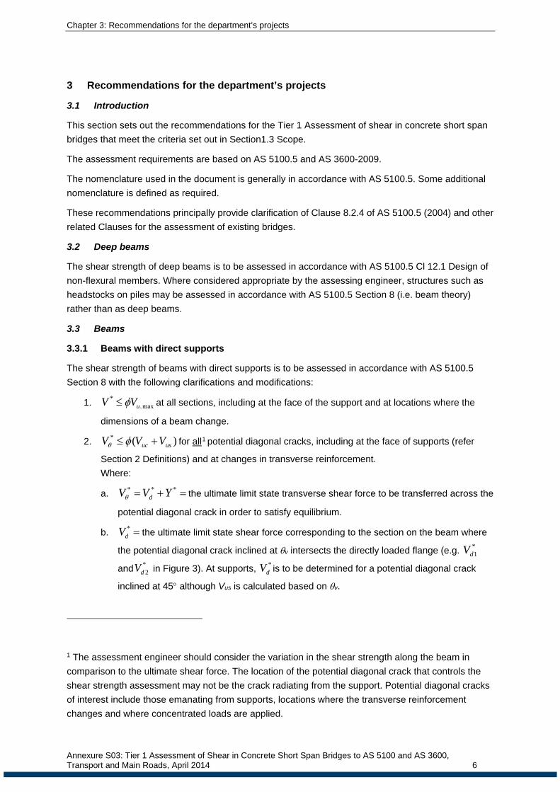
3.3.1 Beams with direct supports
The shear strength of beams with direct supports is to be assessed in accordance with AS 5100.5 Section 8 with the following clarifications and modifications:
1. max.*
uVV φ≤ at all sections, including at the face of the support and at locations where the
dimensions of a beam change.
2. )(*usuc VVV +≤φθ for all1 potential diagonal cracks, including at the face of supports (refer
Section 2 Definitions) and at changes in transverse reinforcement. Where:
a. =+= *** YVV dθ the ultimate limit state transverse shear force to be transferred across the
potential diagonal crack in order to satisfy equilibrium.
b. =*dV the ultimate limit state shear force corresponding to the section on the beam where
the potential diagonal crack inclined at θv intersects the directly loaded flange (e.g. *1dV
and *2dV in Figure 3). At supports, *
dV is to be determined for a potential diagonal crack
inclined at 45° although Vus is calculated based on θv.
1 The assessment engineer should consider the variation in the shear strength along the beam in comparison to the ultimate shear force. The location of the potential diagonal crack that controls the shear strength assessment may not be the crack radiating from the support. Potential diagonal cracks of interest include those emanating from supports, locations where the transverse reinforcement changes and where concentrated loads are applied.
Annexure S03: Tier 1 Assessment of Shear in Concrete Short Span Bridges to AS 5100 and AS 3600, Transport and Main Roads, April 2014 6

Chapter 3: Recommendations for the department’s projects
c. Y * = the sum of any indirect loads applied to the portion of the beam between the potential diagonal crack, the indirectly loaded flange and the section at which shear is calculated (refer shaded areas in Figure 3).
Figure 3: Calculation of the shear force to be transferred across potential diagonal cracks for a beam loaded with direct and indirect loads
d. For beams subjected to direct loads and self-weight only, Y * = 0 and **dVV =θ .
e. For beams subject to indirect loads only, it is conservative to assume all the indirect loads are applied at the indirect flange and ****
id VYVV ≈+=θ where =*iV the ultimate limit
state shear force corresponding to the section on the beam where the potential diagonal crack inclined at θv intersects the indirectly loaded flange (e.g. *
1iV and *2iV in Figure 3).
The distribution of shear/suspension reinforcement in the vicinity of concentrated indirect loads and other local failure paths may need further consideration as per AS 5100.5 with particular reference to AS 5100.5 Appendix D.
f. For perpendicular shear reinforcement, vofsysv
us dfs
AV θcot.= where Asv/s is taken at
the centre of the potential diagonal crack. Near locations where Asv/s changes, the quantity Asv/s may be assumed to vary linearly over a length do centred on the location where the Asv/s changes (refer Figure 4).
Crack - Crack -
Shear Force Diagram
Beam Elevation
Potential diagonal cracks
do
Y*
θv 45°
Directly loaded flange
Indirectly loaded flange
Annexure S03: Tier 1 Assessment of Shear in Concrete Short Span Bridges to AS 5100 and AS 3600, Transport and Main Roads, April 2014 7

Chapter 3: Recommendations for the department’s projects
Figure 4: Determination of Asv/s for shear capacity calculations
3. β3 = 1.0
4. Calculation of β1 for beams only (i.e. not for slabs):
a. if Asv ≥ Asv.min, β1 = 1.1(1.6 - do/1000) ≥ 1.1
b. otherwise β1 is not defined in AS5100.5 and a Tier 2 shear assessment shall be undertaken as per Annexure S04: Tier 2 Assessment of Shear in Concrete Short Span Bridges
5. θv is to be taken to vary linearly from 30° when V* equals φ Vu.min to 45° when V* equals φVu.max as per Cl 8.2.10. When Asv is less than Asv.min, θv is to be taken as 30°.
6. Vuc shall be calculated for the section where the shear force is calculated. The area Ast used shall be that which is in tension under the loading which produces the shear force being considered. Ast is that area of longitudinal reinforcement provided in the tension zone and fully anchored at the cross section under consideration. Should the longitudinal reinforcement be partially anchored then reduce Ast to the portion of the full anchorage achieved times Ast.
7. The extent provisions of AS 5100.5 Cl 8.2.12.3 are deemed to be satisfied provided that all potential diagonal cracks are assessed and the effects of indirect loads are considered as per #2 above.
8. In the case when the support is narrower than the beam at the face of the support, flag for Tier 2 assessment if the assessments for φVu.max control when φVu.max is calculated using bv equal to the width of the support.
3.3.2 Beams with indirect supports
Beams subject to indirect supports, including stepped joints, are to be assessed as per Section 3.3.1 with the following additional requirements:
Annexure S03: Tier 1 Assessment of Shear in Concrete Short Span Bridges to AS 5100 and AS 3600, Transport and Main Roads, April 2014 8

Chapter 3: Recommendations for the department’s projects
1. The disturbed regions in the vicinity of the indirect supports are to be assessed using AS 5100.5 Cl 12.1 Design of non-flexural members and AS 5100.5 Appendix D.
2. The suspension reinforcement is required to support 100% of the suspension force determined from the strut-tie analysis.
3. The face of the support is to be taken as:
a. the face of the suspension reinforcement in the case of beam junctions
b. as informed by strut-tie theory for stepped joints.
3.4 Detailing of reinforcement
The detailing provisions for flexural and shear reinforcement are to be reflected in the assessments for bending and shear at all sections:
1. The calculated bending strength of a member is to be reduced from the nominal bending strength at sections away from the points of maximum moment in order for the assessment to reflect the detailing requirements of AS 5100.5 Cl 8.1.8.2. (These requirements are necessary to ensure the shear capacity of the member).
2. The shear strength assessment at the face of the support is to reflect the anchorage requirement of Cl 8.1.8.3.
3. AS 3600–2009 development lengths are to be adopted with the following additional information for historical reinforcement.
Replace AS 3600_2009 Eq 13.1.2.2 with:
bsy
c
bsytbsy dfk
fk
dfkkL 1'
2
31. 058.0
5.0≥=
Replace the AS 3600-2009 C13.2.4(a) minimum lapped splice length in compression of 40db with:
For 'cf ≤ 20 MPa:
0.097fsydb ≥ 400mm for fsy < 410 MPa (0.175fsy - 32)db ≥ 400mm for fsy > 410 MPa
For 'cf > 20 MPa:
0.07fsydb ≥ 300mm for fsy < 400 MPa (0.125fsy - 22)db ≥ 300mm for fsy > 400 MPa
3.5 Shear strength of prestressed concrete members
The shear strength of prestressed concrete “I” girders shall be calculated in accordance with Annexure S04: Tier 2 Assessment of Shear in Concrete Short Span Bridges. The shear strength of other prestressed concrete members shall be calculated as per this annexure and AS 100.5 as appropriate.
The critical section for simply supported prismatic prestressed concrete girders is commonly found between d from the support and ¼ span. For the purposes of Tier 1 Assessments, it is acceptable to assess the shear at 3 locations: d from face, midway between d from the face and ¼ span, and ¼ span.
Annexure S03: Tier 1 Assessment of Shear in Concrete Short Span Bridges to AS 5100 and AS 3600, Transport and Main Roads, April 2014 9

Chapter 3: Recommendations for the department’s projects
The shear strength of standard Transport and Main Road’s transversely stressed prestressed concrete deck units is to be assessed as a slab in accordance with AS 5100.5. The minimum shear reinforcement provisions of AS 5100.5 Cl 8.2.8 are not applicable to the department’s transversely stressed prestressed concrete deck units.
Annexure S03: Tier 1 Assessment of Shear in Concrete Short Span Bridges to AS 5100 and AS 3600, Transport and Main Roads, April 2014 10
Chapter 4: Further work
4 Further work
Other proposed work includes:
• combined bending shear and torsion
• anchorage requirements for prestressed concrete members at simple supports
• effects on the shear strength of beams where additional shear reinforcement is required due to termination of flexural reinforcement
• alternate code clauses for AS 5100.5 for use in assessment
• changes in AS 5100.5
• shear strength of prestressed concrete “I” girders.
It is acknowledged that whilst the title addresses the assessment of existing short-span bridges, the scope of applicability is more extensive. It is noted that the approach to the design of new bridges is somewhat different.
Annexure S03: Tier 1 Assessment of Shear in Concrete Short Span Bridges to AS 5100 and AS 3600, Transport and Main Roads, August 2013 11

Chapter 5: Bibliography
5 Bibliography
American Concrete Institute (1987), Shear Strength of Reinforced Concrete Members – ACI 426R, Manual of Concrete Practice,
CCAA & Standards Australia, 2011, “T38 / HB71-2002 Reinforced Concrete Design in accordance with AS 3600–2009”.
Foster SJ, Kilpatrick AS & Warner, RF, 2010, “Reinforced Concrete Basics 2E – Analysis and design of reinforced concrete structures”, Pearson Australia, Frenchs Forest.
Reineck KH, 1990, Lecture Notes for Structural Concrete Design for Constructability, University of Stuttgart in conjunction with The University of Melbourne, The University of Technology Sydney, Queensland University of Technology, The University of Canterbury, Curtin University of Technology.
Standards Australia, 2009, “AS 3600–2009 Concrete Structures”
Standards Australia, 2004, “AS 5100.5–2004 Bridge Design Part 5: Concrete”
Standards Australia, 2008, “AS 5100.5 Supp 1-2008 Bridge Design–Concrete–Commentary (Supplement to AS 5100.5–2004)”
Standards Australia, 1974, “AS 1480–1974 SAA Concrete Structures Code”
Warner RF, Rangan BV & Hall AS, 1995, “Concrete Structures”, 3rd Edition, Longman, Sydney.
Warner RF, Rangan BV, Hall AS & Faulkes KA, 1998, “Concrete Structures”, Longman, Sydney.
Annexure S03: Tier 1 Assessment of Shear in Concrete Short Span Bridges to AS 5100 and AS 3600, Transport and Main Roads, August 2013 12

Appendix A: Background information
Appendix A Background information
A.1 Introduction
This appendix provides the technical background and commentary to Section 3 Recommendations for the department’s projects.
A.2 Overview of AS 5100.5 and AS 3600 Shear Provisions
AS 5100.5–2004 was derived from AS 3600–2001, consequently these two codes are very similar. AS 3600 was subsequently revised in 2009. The changes incorporated in AS 3600–2009 that are relevant to shear in reinforced concrete include revisions to the development length of reinforcement and the addition of a new section on strut-tie modelling.
AS 5100 is currently under review by Standards Australia. The AS 5100.5–2004 provisions, supplemented by AS 3600–2009 and the Commentary to AS 5100.5–2004, are adopted in the discussion that follows. Quotes are shown in italics.
The provisions relevant to the assessment of shear in headstocks include:
• Design of beams for strength and serviceability (Section 8): This section is commonly applied to the assessment of girders and headstocks but does not apply to non-flexural members covered by Section 12. The section is not applicable to some headstocks such as headstocks on closely spaced piles or headstocks with short cantilevers although, it is common practice to assess small structures such as headstocks on piles as if they were beams.
• Design of non-flexural members, end zones and bearing surfaces (Section 12): This section applies to the design of non-flexural members… where the ratio of the clear span or projection to the overall depth is less than—
a) For cantilevers 1.5;
b) For simply supported members 3 and;
c) For continuous members 4
The section also applies to the design of non-flexural regions.
There is a gradual transition from full flexural action to non-flexural action and the change from one action to the other is not abrupt (AS 5100 C12.1.1.1). Section 12 is relevant to headstocks on closely spaced piles and short cantilevers within headstocks. However, it is common practice to assess small structures such as headstocks on piles as if they were beams.
• Strut-tie modelling (AS 3600 Section 7): This new section in AS 3600–2009 applies to the conditions at overload and at failure in non-flexural members (Section 12) and non-flexural regions of members as a basis both for strength design and for evaluating strength. The angle between the axes of any strut and any tie shall not be less than 30° in reinforced concrete elements. This section provides the basis for applying strut-tie modelling for the assessment of non-flexural members and non-flexural regions of members (Section 12).
A.3 B and D regions
The behaviour of concrete structures in shear varies between B-regions and D-regions (refer Figure 5). D-regions correspond to areas of discontinuity such as supports, concentrations of loads or changes in section and extend a distance approximately equal to the depth of the member on either
Annexure S03: Tier 1 Assessment of Shear in Concrete Short Span Bridges to AS 5100 and AS 3600, Transport and Main Roads, August 2013 13

Appendix A: Background information
side of the discontinuity. The remaining regions of the beam are referred to as B-regions – flexural areas where the assumption that plane sections remain plane can be applied (CCAA T38, 2011).
Figure 5: Examples of B and D regions (Figure 9.3 CCAA T38, 2011)
AS 5100.5 Section 8 is focused on the B-regions of beams (i.e. beam theory), with some adaptations for D-regions near supports (e.g. Cl 8.2.4). AS 5100.5 Section 12 and AS 3600 Sections 7 and 12 are focused on the D-regions in beams and non-flexural members (i.e. strut-tie theory).
Tests have shown that when the ratio of the shear-span (“a” in Figure 6) to the depth of the member is small then the shear capacity is considerably enhanced (refer Figure 6). The tests results of primary interest, where a/d < 2, are dominated by D-regions. AS 5100/AS 3600 provides two methods to account for this: utilise strut-tie modelling (AS 5100 Section 12 / AS 3600 Sections 7 and 12); or through the application of a factor (β3) to account for this “shear-span to depth effect” in the calculation of Vuc (Section 8). Section 8 provides a relatively straightforward design method but requires the location of the critical section for shear to be taken at the face of the support rather than do from the face of the support.
Figure 6: Effect of shear-span shear strength: (a) typical shear test arrangements, showing overlapping D-regions and shear span “a”; (b) effect of (a/d) on shear strength (refer Figure C8.2.7(C) AS 5100.5 commentary)
(a) (b)
L a a
Annexure S03: Tier 1 Assessment of Shear in Concrete Short Span Bridges to AS 5100 and AS 3600, Transport and Main Roads, August 2013 14
Appendix A: Background information
Nevertheless, there have been many variations in interpretation of the shear provisions with some suggesting that the provisions are not consistent within the standard and not consistent with the commentary. It has also been postulated that the standard and commentary are inconsistent.
A.4 Beam Shear Theory – direct loads and direct supports
Members loaded on one face and supported on the opposite face are said to be “directly loaded” and “directly supported” (refer Section 2 Definitions). Most beam tests have been direct as the loads and the reactions are applied to the top and bottom of the beam, respectively (ACI 1980). Shear in beams with direct loads and direct supports is discussed in this Section. Additional requirements for “indirectly loaded” members are discussed in Section A.5, including stepped joints, hanging supports and beam junctions.
The beam theory adopted by AS 5100.5 Section 8 utilises a combination of an empirical calculation of the concrete shear capacity (Vuc) and the truss analogy (Vus) to calculate the contribution of the shear reinforcement. A discussion of some of the background to beam shear theory follows.
1. The shear strength is the sum of the shear strength of the concrete (Vuc) and the shear strength of the shear reinforcement (Vus):
Vu = Vuc + Vus
Vuc is derived from an empirical relationship. Vus is derived from a variable angle truss analogy.
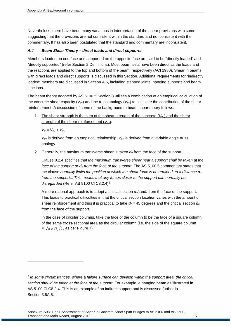
2. Generally, the maximum transverse shear is taken do from the face of the support:
Clause 8.2.4 specifies that the maximum transverse shear near a support shall be taken at the face of the support or do from the face of the support. The AS 5100.5 commentary states that the clause normally limits the position at which the shear force is determined, to a distance do
from the support... This means that any forces closer to the support can normally be disregarded (Refer AS 5100 Cl C8.2.4)2.
A more rational approach is to adopt a critical section do/tanθv from the face of the support. This leads to practical difficulties in that the critical section location varies with the amount of shear reinforcement and thus it is practical to take θv = 45 degrees and the critical section do from the face of the support.
In the case of circular columns, take the face of the column to be the face of a square column of the same cross-sectional area as the circular column (i.e. the side of the square column = 2cD×π , as per Figure 7).
2 In some circumstances, where a failure surface can develop within the support area, the critical section should be taken at the face of the support. For example, a hanging beam as illustrated in AS 5100 Cl C8.2.4. This is an example of an indirect support and is discussed further in Section 3.5A.5.
Annexure S03: Tier 1 Assessment of Shear in Concrete Short Span Bridges to AS 5100 and AS 3600, Transport and Main Roads, August 2013 15

Appendix A: Background information
Figure 7: Face of support for a circular column
Strut-tie theory can be used to inform the transfer of shear forces to supports that are non-rectangular or non-circular.
When a support is a flexible bearing, BD44 recommends that in the case of flexible bearings, the face of the support should be taken at the centre line of the bearing (BD 44 Cl 5.3.3.3). This is consistent with the observation that the diagonal compression struts must be supported by the entire width of the bearing rather than by a local compression strut near the face of a solid support.
3. There is a shear-span to depth effect (β3) close to supports:
This factor (β3) is usually unity, but may increase up to a maximum of 2. It is an established parameter for the influence of proximity of the load to the support. This is a conservative factor and can be related to test results… (Refer Figure 6 and AS 5100 Cl C8.2.7.1(e)).
These test results have typically been for simply supported beams subjected to concentrated loads rather than distributed loads, suggesting that the application of this factor should be restricted to beams subject to concentrated loads. Texts such as “Concrete Structures” (Warner, Rangan, Hall & Faulkes, 1998) and “Reinforced Concrete” (Warner, Rangan & Hall, 1995) recommend that β3 = 1.0 unless:
Face of Support
Dc
Annexure S03: Tier 1 Assessment of Shear in Concrete Short Span Bridges to AS 5100 and AS 3600, Transport and Main Roads, August 2013 16

Appendix A: Background information
− the concentrated load is applied to the top surface of a beam within 2do of a support
− the concentrated load accounts for more than 60% of the shear – described in this document as a dominant concentrated load
− the concentrated load and the support are so orientated as to create diagonal compression in the beam between the concentrated load and the support.
This suggests:
− β3 = 1.0 for beams subject to distributed loads (refer Figure 8(a)) or concentrated loads that are applied further than 2do from a support (refer Figure 8(b)) or concentrated loads that are applied within 2do of a support but are not dominant concentrated loads (refer Figure 8(c)). This is the case for deck unit bridges and for those girder bridges where a significant number of girders are supported by a segment of a headstock spanning between columns.
− β3 = 2do/av but where 1 ≤ β3 ≤ 2 for beams subject to a dominant concentrated load that is applied within 2do of a support (refer Figure 9). This may apply to headstock elements supporting smaller numbers of girders. It does not apply to headstocks on deck unit bridges. It only applies when there is a direct compression strut that can form between the dominant concentrated load and the support (refer Figure 9).
Annexure S03: Tier 1 Assessment of Shear in Concrete Short Span Bridges to AS 5100 and AS 3600, Transport and Main Roads, August 2013 17

Appendix A: Background information
Figure 8: Reinforced concrete beams where β3 = 1.0: (a) Uniformly distributed load, (b) Concentrated load located further than 2do from the face of the support, (c) Non-dominant concentrated load (i.e. P* < 0.6V*(xa)) located within 2do from the face of the support
(a)
2do
do
V*
P*
xP > 2do
V*(xa)
V*(xb)
xP P*
xP < 2do
P*<0.6V*(xa)
2do
V*(xb)
V*(xa)
(b)
(c)
xP
Annexure S03: Tier 1 Assessment of Shear in Concrete Short Span Bridges to AS 5100 and AS 3600, Transport and Main Roads, August 2013 18

Appendix A: Background information
Figure 9: Reinforced concrete beams where β3 = 2do/av
It is noted that one undesirable consequence of implementing a system reliant on a dominant concentrated load is the introduction of a non-linearity in the calculated strength of the beam that is dependent on the load.
Some argue that the experimental evidence supports enhancement and that it should apply to all load types and that a dominant concentrated load is not required, despite the experimental evidence only being for dominant concentrated loads. For example, BD 44/95 applies shear enhancement to beam theory irrespective of the loading type, provided the bending reinforcement is anchored at the supports.
Shear enhancement factors such as β3 are not universally applied. An alternate strategy is to argue that beam theory should not be applied to the disturbed regions near supports and that strut-tie theory is appropriate in these regions especially where there is a concentration of load that can be transmitted directly to the support via a compression strut as per Figure 9, for example. This philosophy is adopted by the American Association of State Highway and Transportation Officials (AASHTO) Bridge Design Code (2007).
Likewise the CHBDC does not apply shear enhancement, rather it has implemented Modified Compression Field Theory for sections where it is reasonable to assume that plane sections remain plane and strut-tie theory elsewhere. The AASHTO Bridge Design Code has also adopted the Canadian initiative with respect to Modified Compression Field Theory.
4. Concrete crushing provides an upper limit of the shear capacity of a beam:
AS 5100.5 Section 8 limits the shear strength to φVu.max – a value determined from the compressive strength of the diagonal struts in the truss model.
AS 5100.5 Section 12 limits the compressive strength of the struts and the nodes.
It is rational to assess concrete crushing at all locations, particularly at the face of the support (location of the maximum shear force) and at locations where the section size of the beam
xp < 2do
P* ≥ 0.6V*(xa)
2do
V*(xa)
V*(xb)
xP
P*
Annexure S03: Tier 1 Assessment of Shear in Concrete Short Span Bridges to AS 5100 and AS 3600, Transport and Main Roads, August 2013 19

Appendix A: Background information
changes. In the case when the column is narrower than the beam at the face of the column, it is considered appropriate to:
− when using strut-tie theory: restrict the width of the compressive strut terminating at the column to the width of the column
− when using beam theory: reduce bv to the width of the column at the face of the column in the calculation of Vu.max.
Figure 10: Headstocks where the width of the support is narrower than the headstock
5. Vus is the sum of the components, in the direction of the shear force, of the yield forces of the steel reinforcement that crosses a shear crack:
When the number, diameter or spacing of ligatures vary over the length of a potential diagonal shear crack, Vus is the component, in the direction of the shear force, of the strength of the ligatures that cross the crack inclined at an angle of θv as illustrated in Figure 11.
bc bv
Annexure S03: Tier 1 Assessment of Shear in Concrete Short Span Bridges to AS 5100 and AS 3600, Transport and Main Roads, August 2013 20

Appendix A: Background information
Figure 11: Variable angle truss model for beam shear
Note that the crack is orientated nominally perpendicular to the direction of principal tension stress. The angle of principal stress can be determined from Mohr’s circle. For directly loaded and supported beams, cracks radiate from the supports and the potential diagonal shear crack considered to calculate the strength of the ligatures is on the support side (direction of increasing shear) of the cross-section located a distance x from the support where the shear is V*(x) (refer Figure 11). The situation is different for indirectly loaded beams and is discussed in Section A.5.
6. The angle of the shear truss θv varies:
In beams, the angle of the shear truss θv varies between 30° (V* = φVu.min) and 45° (V* = φVu.max) (refer AS 5100 Cl 8.2.10). This angle varies along the beam (refer Figure 11) and may require an iterative calculation to determine. AS 3600–2009 indicates that this is the minimum angle (θv.min) and the truss angle θv can be chosen to be between θv.min and 60°. This leads to an inconsistency in both AS 3600 and AS 5100 as described below.
At the face of a support where the compression strut radiates from the support, shear cracking will radiate from the support (refer Figure 12). Taking the shear do from the face of the support (V*(do)) implies the compression struts are orientated at 45°. A consistent assessment approach would be to only consider the ligatures over the length do from the face of the support as contributing to Vus (i.e. the ligatures crossing the crack indicated by the solid line in Figure 12). However, when assessing shear capacity in accordance with AS 5100, a value of θv less than 45° will normally be determined. Using θv less than 45° when calculating Vus
θv
x
V*(x)
V*(x)
M*(x)
Annexure S03: Tier 1 Assessment of Shear in Concrete Short Span Bridges to AS 5100 and AS 3600, Transport and Main Roads, August 2013 21

Appendix A: Background information
includes ligatures over a distance do/tanθv (i.e. ligatures crossing the crack indicated by the dashed line in Figure 12). Thus, some ligatures beyond the section at do are taken to be contributing to the shear strength at do. This inconsistency is inherent in the code and is standard design practice.
This inconsistency further complicates the assessment of members where the shear reinforcement (Asv/s) reduces significantly in proximity of the support. Near the support the shear is calculated based on a 45 degree crack whereas the strength is based on θv. In contrast, away form the support both the shear and the strength are both depend on θv. In some cases there may need to be a transition between the two methods associated with the shear at the support and the shear away from the support. It is suggested that this transition should occur over a distance do. For example, in Figure 12 the shear associated with a crack radiating from the support will be V*(do) and the shear associated with a crack radiating from a point do from the support would correspond to V*(do + do//tanθv) with the shear associated with crack radiating from a point between these two points determined using linear interpolation.
Annexure S03: Tier 1 Assessment of Shear in Concrete Short Span Bridges to AS 5100 and AS 3600, Transport and Main Roads, August 2013 22

Appendix A: Background information
Figure 12: Shear near headstock supports in deck unit bridges. Headstock exhibits a step change in shear reinforcement near the support.
In design, the detailing requirements of AS 5100.5 ensure that the shear reinforcement is provided between the critical section and the support and extends a distance D from the section under consideration in the direction of decreasing shear (Cl 8.2.12.3). When assessing beams where this extension has not been provided, the actual shear reinforcement crossed by a crack is considered. The CHBDC has an approach that utilises an average ‘s’ over the length of the potential diagonal crack although the average is taken over a length do rather than do/tanθv (refer dashed line in Figure 12). This effectively weights the average calculation towards the centre of the crack. In some bridges Asv also varies. Hence the recommendation that Asv/s be taken at the centre of the potential diagonal crack. Near locations where Asv/s changes, the quantity Asv/s may be assumed to vary linearly over a length do centred on the location where the Asv/s changes. Refer also Figure 13.
Note: In strut-tie theory, the angle between the axes of any strut and any tie shall not be less than 30° in reinforced concrete elements (AS 3600 Cl 7.1(g)).
θv
x
V*(do) V*(0)
V*(do/tanθv)
do
Asv/s
Asv/s averaged over do
do
V*(do+do/tanθv)
Annexure S03: Tier 1 Assessment of Shear in Concrete Short Span Bridges to AS 5100 and AS 3600, Transport and Main Roads, August 2013 23

Appendix A: Background information
Figure 13: Determination of Asv/s for shear capacity calculations
7. Adequate detailing of the flexural reinforcement is essential to gain full shear strength:
The bending strength needs to exceed the applied bending moment at a section in order for there to be capacity to resist shear. This additional bending capacity enables inclined shear cracks to develop and cross ligatures thereby generating the desired shear capacity. To illustrate this, consider the cross-section through a B-region of the beam presented in Figure 14.
Figure 14: Forces acting on a cross-section
For equilibrium in the direction of the shear:
vdCV θSin= or vd VC θSin=
where Cd is the resultant compression force in the inclined struts.
For axial equilibrium:
vdCCT θCos+= or vVCT θTan+=
For bending equilibrium (assuming resultant of Cd is midway between T and C):
Annexure S03: Tier 1 Assessment of Shear in Concrete Short Span Bridges to AS 5100 and AS 3600, Transport and Main Roads, August 2013 24

Appendix A: Background information
2Cos
vdCTM θ−= or
−=
v
VTMθTan2
or v
VMTθTan2
+=
Thus at any section along a beam where there is shear, the tension force in the bending reinforcement must be increased beyond the force required to resist bending alone (Error! Bookmark not defined. M ) by )Tan2( vV θ , in order satisfy both the bending and shear
requirements. The reinforcement supplied to resist this force must then be anchored on both sides of the section. This requires that the flexural reinforcement is extended further, before it is terminated, than would be required if the bending moment envelope was considered in isolation of the shear.
This is expressed in AS 5100 Cl 8.1.8.2: The termination and anchorage of flexural reinforcement shall be based on a hypothetical bending-moment diagram formed by uniformly displacing the calculated positive and negative bending-moment envelopes a distance D along the beam each side of the relevant sections of maximum moment. Although these provisions are part of the flexural reinforcement requirements, their purpose is actually to ensure that the shear requirements are met.
In assessment, the reinforcement is known and thus the bending strength without shear (φMu) can be calculated at each position on the beam and a bending strength with shear (φMu.v) determined after adjustment for the development length of the reinforcement and displacing the bending strength with shear (φMu) a distance D along the beam as illustrated in Figure 15 – a procedure that is the reverse of the design approach and the “hypothetical bending-moment diagram” of AS 5100 Cl 8.1.8.2. In this way, the calculated bending moment envelopes (M *) can be compared directly with the bending strength with shear (φMu.v) at the same location and thus determine, by a comparison of bending moments, if the bending and detailing requirements are met at a section.
Annexure S03: Tier 1 Assessment of Shear in Concrete Short Span Bridges to AS 5100 and AS 3600, Transport and Main Roads, August 2013 25

Appendix A: Background information
Figure 15: Hypothetical bending strength of a beam for assessment of the bending strength and flexural reinforcement detailing requirements
The additional tension due to shear should never result in an increase in tension reinforcing beyond that required for peak moment alone for direct support conditions3. This is apparent for midspan moments in beams supporting distributed loads because the shear is zero at the point of maximum moment. However, at the face of the support there is a co-existing peak bending moment and a large shear. In this situation the truss is a fan (D-region) rather than a parallel chorded truss (B-region) and the angle of cracking approaches 90° (i.e. flexural cracking) and no additional tension reinforcing is required. A similar scenario arises under concentrated loads near midspan.
Note that the critical section for negative bending is not at the face of the column but 0.15xwidth of column into the column. In the case of headstocks that cantilever from blade piers then the location of the critical section can be informed by the width of the compression strut in the pier that is required to support the loads from the cantilever.
At simple supports, AS 5100.5 requires that sufficient positive reinforcement shall be anchored past the face of the support for a length such that the anchored tensile reinforcement can develop a tensile forces of 1.5V* at the face of the support, where V* is the design shear force at a distance d from that face. This provision is irrespective of the truss angle. The strut-tie approach provides opportunities for refinement:
3 Refer Section 3.5A.5.3 or a discussion regarding the additional tension force required for shear in indirectly supported girders.
Acceptable M* envelopes
D D
D D Lsy.t Lsy.t
Lsy.t Lsy.t
φMu.v Bending strength with shear
φMu Bending strength without shear
A critical section for bending
Unacceptable M* envelopes
D
Annexure S03: Tier 1 Assessment of Shear in Concrete Short Span Bridges to AS 5100 and AS 3600, Transport and Main Roads, August 2013 26

Appendix A: Background information
a. Dominant concentrated load near support: In this case the shear is carried by a compression strut between the support and the load. Assuming that the entire shear is applied by a dominant concentrated load a distance x from the support requires
)(tanθVT = where x=θtan and V is the reaction. This translates to a tensile force
between 1.73V* and 0 for θ between 30° and 90° respectively.
b. Distributed load: In this case, assuming the entire shear is carried by the shear reinforcement (as per strut-tie theory) then, at a simple support where M = 0, a tensile force )Tan2( vVT θ= is to be anchored. This translates to a tensile force of 0.9V* and
0.5V* for truss angles of 30° and 45° respectively.
In both of these cases, V* is the shear at the face of the support and the other tension forces from restraint and torsion need to be added to obtain the tensile force T which needs to be resisted by the reinforcement (i.e. T ≤ φAstfsy ) anchored beyond the face of the support.
8. Minimum reinforcement requirements:
Beams without shear reinforcement can fail quickly at loads not much greater than the shear cracking load. For this reason, AS 5100.5 and other Standards set out minimum reinforcement requirements (Asv.min). A number of Queensland bridges have been identified with headstocks where Asv is less than Asv.min.
Most shear provisions, including AS 5100.5, are semi-empirical and are based on beam tests. These provisions apply to slabs without shear reinforcement and for beams (of the typical dimensions found in bridges) with at least the minimum reinforcement. Thus, there is some risk with applying the design provisions in the assessment of beams with Asv < Asv.min.
The CHBDC includes provisions for evaluating the shear strength of beams with zero and less than minimum shear reinforcement. The CHBDC is based around a rational approach to the calculation of the shear strength of beams and is derived from modified compression field theory developed at the University of Toronto by Collins and his colleagues. This theory can also be found in the AASHTO LRFD Design Specifications.
Evaluation of the shear strength of concrete beams with small amounts of shear reinforcement has shown that strengths estimated by applying AS 5100.5 when Asv < Asv.min can be non-conservative when compared to the CHBDC. This, in combination with the reduced ductility of sections with less than minimum shear reinforcement, has led to the conclusion that the shear strength of beams with less than minimum shear reinforcement should be assessed using Standards such as the CHBDC that specifically address the strength of beams with Asv < Asv.min.
For the above reasons, in Tier 1 Assessments, β1 has been set to 0.0 for all beams (not slabs) where Asv < Asv.min. This has the effect of setting Vuc = 0 and thus Vu = Vus. The consequence will be low ERBs and SARs, thus flagging the bridge for a review and possibly a Tier 2 assessment. This is an interim position and may be revised after further investigation.
9. Members tapered in depth:
AS 3600 Cl 8.2.3 states: In members that taper in depth along their length, the components of inclined tension or compressive forces shall be taken into account in the calculation of shear strength. This can provide significant enhancement to the shear capacity of members that taper in depth. Where the line of the centroid of the tension or compression force is inclined,
Annexure S03: Tier 1 Assessment of Shear in Concrete Short Span Bridges to AS 5100 and AS 3600, Transport and Main Roads, August 2013 27

Appendix A: Background information
the vertical component of the force can be added in a manner similar to the vertical component of the prestress (PV) (refer Figure 16 and AS 5100.5 Cl 8.2.3).
Figure 16: Enhancement to shear capacity due to the components of inclined tension or compressive forces in members tapered in depth
The location of the maximum transverse shear near supports of tapered members (V*(45°)) is determined by considering a potential diagonal crack emanating from the support at an inclination of 45° until it intersects the flexural reinforcement at the opposite face. This defines the section where the shear force, bending moment and the parameters (bw, do, Ast and the vertical component of the compression force) used in the calculation of Vuc are determined. Ast is that area of longitudinal reinforcement provided in the tension zone and fully anchored at the cross section under consideration. Should the longitudinal reinforcement be partially anchored then reduce Ast to the portion of the full anchorage achieved times Ast. Where both top and bottom reinforcement are provided, the area Ast used shall be that which is in tension under the loading which produces the shear force being considered. This would correspond to the top layer of reinforcement in Figure 17. (Note: This is intended to be a conservative approach).
Vertical component
C
P*
Vertical
component
P*
Annexure S03: Tier 1 Assessment of Shear in Concrete Short Span Bridges to AS 5100 and AS 3600, Transport and Main Roads, August 2013 28

Appendix A: Background information
Figure 17: Maximum shear near supports in tapered members
All potential diagonal cracks need to be assessed. For example, a potential diagonal crack adjacent to the load in Figure 17 may be more critical than the crack that radiates from the support.
A.5 Beam Shear Theory – indirect loads/supports
A.5.1 Introduction
In most beam tests the loads and the reactions are applied to the top and bottom of the beam, respectively (ACI 1980). Such beams are said to have “direct loads” and “direct supports” and were discussed in Section A.4. This section of this appendix discusses indirect support situations where there is no direct compressive load path between the load and the support or where there is a geometrical discontinuity.
Strut-tie theory and equilibrium of the free-body diagram formed by a potential diagonal shear crack provides the basis for determining the additional requirements for non-standard beams and joints.
A.5.2 Beams with indirect loads/supports
This section summarises the effect on assessment of beams where the loads and/or the supports are indirect. Beams with both direct loads and direct supports (i.e. as per Section A.4) are also presented for comparison. Note that self-weight of the beam/slab is regarded as a direct load despite being applied through the centroid of the beam.
45°
do
V*(45°)
Ast
Annexure S03: Tier 1 Assessment of Shear in Concrete Short Span Bridges to AS 5100 and AS 3600, Transport and Main Roads, August 2013 29

Appendix A: Background information
This is the directly loaded and supported reference case:
Location of maximum shear considered: do from face of support
Vus: Vertical component of shear reinforcement crossed by a crack between face of support and do/tanθv from the face of the support.
Additional requirements: None
Extent: The entire beam is considered “direct”.
Location of maximum shear considered: do from face of support
Vus: Vertical component of shear reinforcement crossed by a crack between face of support and do/tanθv from the face of the support.
Additional requirements: Suspension reinforcement required to resist entire reaction. This is in addition to the shear reinforcement. Suspension reinforcement must enclose the bottom reinforcement which needs to satisfy the anchorage requirements past the face of the suspension reinforcement if it is a simple support.
Extent: Only the disturbed region surrounding the suspension reinforcement is considered “indirect”. The balance of the beam is “direct”.
Refer also to AS 5100.5 Appendix D Suspension Reinforcement Design Procedures.
(a) Loads on top, supported from bottom (“direct loads, direct supports”)
(b) Loads on top, supported from top (“direct loads, indirect supports”)
Annexure S03: Tier 1 Assessment of Shear in Concrete Short Span Bridges to AS 5100 and AS 3600, Transport and Main Roads, August 2013 30

Appendix A: Background information
Where gdo = distance from the “direct” flange to the centroid of the applied load.
Location of maximum shear considered: (1 - g)do from face of support. If the load applied to the top of the beam (i.e. g = 0) then the location to be considered is do from the face of the support as per cases (a) and (b). If the load is applied half way down the side (i.e. g = 0.5), the critical location to be considered will be do/2 from the face of the support. If the loads are applied at the bottom (g = 0.0) then the location to be considered is at the face of the support. This is consistent with the equilibrium of the free-body diagram.
Vus: Vertical component of shear reinforcement crossed by a crack between face of support and do/tanθv from the face of the support. Away from the support, Vus = the vertical component of the shear reinforcement crossed by a potential diagonal crack with a horizontal projection of do/(tanθv) but offset from the section where the shear is being assessed by a distance gdo/(tanθv) in the direction of increasing shear.
Additional requirements: None
Extent: The entire beam is considered “indirect”. The supports are considered “direct”.
gdo
do/tanθv gdo/tanθv
V*
V*45
gdo
(c) Loads on side, supported from bottom (“indirect loads, direct supports”)
Annexure S03: Tier 1 Assessment of Shear in Concrete Short Span Bridges to AS 5100 and AS 3600, Transport and Main Roads, August 2013 31

Appendix A: Background information
As for (c) Loads on side, supported on the bottom except suspension reinforcement is required.
Additional requirements: Suspension reinforcement generally required to resist entire reaction. This is in addition to the shear reinforcement. Suspension reinforcement must enclose bottom reinforcement which needs to satisfy the anchorage requirements past the face of the suspension reinforcement if it is a simple support.
Extent: The entire beam and its supports are considered “indirect”.
Design codes such as AS 5100.5 are generally based around the most common scenario of direct loads and direct supports. However codes also include detailing requirements to ensure that the effects of direct and indirect loads and supports are incorporated. This is achieved through a combination of the location at which the shear is calculated near a support and requirements to extend shear reinforcement back to the support and D beyond the location where it is required. In addition, indirect loads are required to be supported by suspension reinforcement, effectively making an indirect load or support a direct load or support.
In assessment, the shear reinforcement is predetermined and these detail requirements may or may not have been complied with. To overcome this limitation, the strength of the shear reinforcement that crosses all potential diagonal cracks needs to be assessed to ensure the critical location is identified. Consequently there is a need to relate the location of the potential diagonal crack with the design shear force.
Figure 18 compares a beam with the load applied directly to the top flange with an identical beam with the same load but applied as in indirect load the bottom flange. In order to satisfy the strength limit state and vertical equilibrium:
ud VV φ≤* for the directly loaded beam and
ui VV φ≤* for the indirectly loaded beam
where: *
dV corresponds to the shear force at the location where the potential diagonal crack
intersects the directly loaded flange *
iV corresponds to the shear force at the location where the potential diagonal crack
intersects the indirectly loaded flange
uVφ is the ultimate limit state capacity of section at the potential diagonal crack.
(d) Loads on side, supported from top (“indirect loads, indirect supports”)
V*45
gdo
Annexure S03: Tier 1 Assessment of Shear in Concrete Short Span Bridges to AS 5100 and AS 3600, Transport and Main Roads, August 2013 32

Appendix A: Background information
Figure 18: Comparison of a beam loaded directly on the top flange and indirectly on the bottom flange
(a) Directly loaded beam
Thus:
• for the directly loaded beam, the capacity of the shear reinforcing over any length do/tanθv must be sufficient to carry the lowest shear over that length, *
dV
φVu
φVu
do/tanθv
(b) Indirectly loaded beam
do
do
(c) Shear force diagram
Annexure S03: Tier 1 Assessment of Shear in Concrete Short Span Bridges to AS 5100 and AS 3600, Transport and Main Roads, August 2013 33

Appendix A: Background information
• for the indirectly loaded beam, the capacity of the shear reinforcing over any length do/tanθv must be sufficient to carry the highest shear over that length, *
iV
• the increased shear capacity required for the indirectly loaded beam is consistent with the requirements to add suspension (AS 5100.5 Cl 8.2.11) or hanging (AS 3600 Cl 8.2.11) reinforcement in the design scenario.
In assessment, it is useful to directly compare the assessed capacity of potential diagonal cracks with the applied shear force while avoiding the numerical complication associated with adjustment for the requirements of suspension reinforcement. This can be achieved provided the locations of the shear force and the potential diagonal crack are both consistent with the centroid of the load, which depends on the loading mix. These locations have been as identified above for direct and indirect loading. There are two broad approaches to this:
1. For a particular potential diagonal crack, calculate the shear strength and determine the location of the corresponding shear force (depending on the direct/indirect loading applied).
2. For a particular location of a shear force, determine the location of the corresponding potential diagonal crack and calculate its shear strength (depending on the direct/indirect loading applied).
In the case of shear, the weakest failure path depends on the section; the actual reinforcement provided; the type of loading; and the magnitude of the loading. These all vary along the beam and thus the critical failure path may not be adjacent to the support. For example, there are many headstocks where the shear reinforcement reduces rapidly and the potential diagonal crack a small distance from the face of the support will be more critical than the potential diagonal crack emanating from the face of the support.
The recommendations in Section 3 are for the general case of a combination of direct and indirect loading. They are based around the approach of identifying potential diagonal cracks of interest and determining the corresponding shear force after consideration of the combination of direct and indirect loads applied.
A.5.3 Flexural reinforcement at indirect supports
As discussed in Section A.4 item 7, additional tension forces are required to resist the shear actions. For structures with direct loads and direct supports, this additional tension due to shear does not increase the tension reinforcing required to resist the peak bending moment. However, there are some circumstances with indirect supports where there may be an increase. Consider, for example, a continuous girder indirectly supported by a headstock framing into the side of the girder (refer Figure 19).
Annexure S03: Tier 1 Assessment of Shear in Concrete Short Span Bridges to AS 5100 and AS 3600, Transport and Main Roads, August 2013 34

Appendix A: Background information
Figure 19: A continuous girder supported on (a) direct or (b) indirect supports
(a) direct support
The “fan” truss model associated with the direct support presented in Figure 19(a) results in peak tension forces in the flexural reinforcement consistent with consideration of the negative moment alone. However, there is an increase in this peak tension force for the “harp” truss arrangement associated with the indirect support presented in Figure 19(b) where the support is provided over the depth of the beam. Thus, in circumstances where the compression struts remain inclined at a point of maximum moment, the harp model shows an additional tension force due to shear. It is possible that at ultimate loads the “harp” may redistribute to become a “fan” provided the suspension reinforcement is adequate.
A.5.4 Stepped joints
Stepped or halving joints involve a geometric non-linearity (refer Figure 20) and as such are D-regions and are assessed using strut-tie theory as per Sections 7 and 12 of AS 3600 and Section 12 of AS 5100.5. Stepped joints are examples of indirect supports.
The reinforcement generally includes both horizontal and vertical reinforcement, and sometimes diagonal reinforcement and prestressing anchorages. These joints are subject to both vertical and horizontal forces. The horizontal forces are controlled by friction in the joint, the stiffness of the bearing and the amount of expected movement, and the accuracy of the installation of the bearing. Horizontal forces are significant in the assessment of stepped joints and therefore should always be considered.
(b) indirect support
Annexure S03: Tier 1 Assessment of Shear in Concrete Short Span Bridges to AS 5100 and AS 3600, Transport and Main Roads, August 2013 35

Appendix A: Background information
Figure 20: An example of a stepped joint incorporating horizontal and vertical reinforcement.
Four strut-tie models are presented corresponding to the various combinations of loads and reinforcement are presented in Figure 21, Figure 22 and Figure 23. The strut-tie arrangements are based on lecture notes prepared by Reineck (1990), except for the alternate arrangement presented in Figure 21(b).
Figure 21: Halving joint strut-tie arrangements – vertical reaction, vertical suspension reinforcement and horizontal nib reinforcement
(a) short horizontal nib reinforcement with additional transverse reinforcement
(b) long horizontal nib reinforcement with less transverse reinforcement
Figure 21 shows the strut-tie arrangement for transferring the vertical reaction to the vertical suspension reinforcement and the horizontal nib reinforcement. Note that the suspension tie shown is located at the centroid of the suspension reinforcement.
Figure 22 shows the strut-tie arrangement for transferring the vertical reaction to diagonal reinforcement. Horizontal reinforcement is required to resist the horizontal forces at the joint.
Annexure S03: Tier 1 Assessment of Shear in Concrete Short Span Bridges to AS 5100 and AS 3600, Transport and Main Roads, August 2013 36

Appendix A: Background information
Figure 23 presents a strut-tie arrangement for the combined vertical and horizontal reaction scenario.
Figure 22: Halving joint strut-tie arrangement – vertical reaction, diagonal reinforcement.
Figure 23: Halving joint strut-tie arrangement – vertical and horizontal reaction, diagonal suspension reinforcement and horizontal nib reinforcement.
In assessment, the strut-tie arrangement adopted will depend on the actual reinforcement provided. In all cases, the tie reinforcement is to be anchored beyond the node.
The effect of the indirect support is limited to the end section of the beam, as indicated by the dashed rounded rectangles in Figure 21 to Figure 23. “Direct” beam methods are applicable beyond less than D from the end of the beam.
A.5.5 Beam junctions
When a secondary beam frames into the side of a primary beam beams, the load from the secondary beam tends to transfer to the bottom of the primary beam, as illustrated by the strut-tie arrangement illustrated in Figure 24. This is an example of an indirect support for the secondary beam.
Annexure S03: Tier 1 Assessment of Shear in Concrete Short Span Bridges to AS 5100 and AS 3600, Transport and Main Roads, August 2013 37

Appendix A: Background information
Figure 24: Junction between a primary and secondary beam of similar depth. Note strut-tie arrangement assumes the junction with the secondary beam corresponds to the maximum moment in the primary beam.
Suspension reinforcement is required to lift 100% of the load (equal to the shear in the secondary beam at the face of the primary beam) from the secondary beam to the compression zone of the primary beam (refer Figure 24). This suspension reinforcement is in addition to the normal shear reinforcement of the primary beam and the secondary beam. The cracking pattern illustrated is only crossed by the suspension reinforcement.
The first potential diagonal crack in the secondary beam radiates from the face of the suspension reinforcement at the junction (refer Figure 24) provided the suspension reinforcement is sufficient to transfer the shear at the face of the primary beam to the compression face of the concrete beam. Thus for direct loads, the maximum shear that requires consideration in the secondary beam remains do
from the face to the support, as per the crack illustrated on the secondary beam.
For the suspension reinforcement to be effective, it needs to enclose the bottom reinforcement of the secondary beam and the top reinforcement of the primary beam.
Two cases where the secondary beam is deeper or shallower than the primary beam are illustrated in Figure 25 and Figure 26, respectively. In both cases suspension reinforcement is required.
Suspension reinforcement
Secondary Beam Primary Beam
Annexure S03: Tier 1 Assessment of Shear in Concrete Short Span Bridges to AS 5100 and AS 3600, Transport and Main Roads, August 2013 38

Appendix A: Background information
Figure 25: Junction between a primary and secondary beam where the secondary beam is deeper than the primary beam with the top surface of the beams aligned
When the secondary beam is deeper than the primary beam as per Figure 25, the suspension reinforcement must resist 100% of the shear at the face of the primary beam. In some cases the suspensions reinforcement may be required in both the primary and the secondary beam, as informed by a strut-and-tie model of the junction.
Suspension reinforcement
Secondary Beam Primary Beam
Annexure S03: Tier 1 Assessment of Shear in Concrete Short Span Bridges to AS 5100 and AS 3600, Transport and Main Roads, August 2013 39

Appendix A: Background information
Figure 26: Junction between a primary and secondary beam where the secondary beam is shallower than the primary beam with the top surface of the beams aligned
When the secondary beam is shallower than the primary beam as per Figure 26, the suspension reinforcement does not need to resist 100% of the shear at the face of the primary beam as compression struts can form in the primary beam. Paulay has suggested the suspension reinforcement should resist Dsecondary/Dprimary times the shear at the face of the primary beam in addition to the shear reinforcement in the primary and secondary beams. The cracking pattern illustrated in Figure 26 crosses both the suspension reinforcement and the primary beam’s shear reinforcement.
It is noted that when the secondary beam is above the primary beam (i.e. compression transfer) then no suspension reinforcement is required. When the secondary beam is below the primary beam (i.e. tension transfer) then 100% of the reaction no suspension reinforcement is required.
For further information refer to Appendix D of AS 5100.5.
A.6 Development lengths and splice lengths
In Australia, AS 3600_2009 incorporates the most recent recommendations for development and splice lengths of reinforcement. It is proposed to undertake assessments in a manner that is consistent with AS 3600_2009. Additional information is required when applying AS 3600_2009 to the assessment of old bridges as the reinforcement in older bridges has lower yield strength and the concrete was weaker compared with the typical concrete used in design. This additional information is discussed below.
Suspension reinforcement
Secondary Beam Primary Beam
Annexure S03: Tier 1 Assessment of Shear in Concrete Short Span Bridges to AS 5100 and AS 3600, Transport and Main Roads, August 2013 40

Appendix A: Background information
A.6.1 Development lengths
AS 3600–2009 calculates development lengths for deformed bars, as follows:
b
c
bsytbsy dk
fk
dfkkL 1'
2
31. 29
5.0≥= AS 3600–2009 Eq 13.1.2.2
While Lsy.tb is a function of both the reinforcement yield strength (fsy) and the concrete strength ( 'cf ),
the minimum development length of 29k1db is independent of yield or concrete strength. A review of older Australian codes reveals that this minimum was 25k1db in AS 5100.5 and AS 3600–2004 and 0.058fsydb in AS 1480–1974. The AS 1480 minimum of 0.058fsydb corresponds to 25db and 29db for fsy equal to 400MPa (AS 5100.5 and AS 3600–2004) and 500MPa (AS 3600–2009) respectively. Thus the minimum of 0.058fsydb is consistent with AS 3600-2009 and is dependent on the yield strength. The following equation for the development length is based on AS 3600–2009 and AS 1480–1974 and reflects the sensitivity to yield strength of the reinforcement necessary for the assessment of older structures:
bsy
c
bsytbsy dfk
fk
dfkkL 1'
2
31. 058.0
5.0≥= AS 3600–2009 Eq 13.1.2.2 modified
for assessment
Refer to AS 3600-2009 for the definition of 321 and , kkk .
A.6.2 Splice lengths in compression
Splice lengths in compression also have a minimum lapped splice lengths that older Australian Standards express as functions of both the yield strength (fsy) and the compression strength ( '
cf )
whereas AS 3600-2009 C13.2.4(a) states that this minimum is 40db and therefore independent on both fsy and '
cf . The various formulations of the minimum compression lapped splice length are as
follows:
AS 5100.5 Cl 13.2.5(a) 0.07fsydb for fsy < 400 MPa (0.125fsy - 22)db for fsy > 400 MPa (This gives 40db at 500 MPa)
AS1480 Cl 11.10.3 For 'cf ≤ 20 MPa:
0.097fsydb ≥ 400mm for fsy < 410 MPa (0.175fsy - 32)db ≥ 400mm for fsy > 410 MPa (This gives 55db at 500 MPa)
For 'cf > 20 MPa:
0.073fsydb ≥ 300mm for fsy < 410 MPa (0.132fsy - 24)db ≥ 300mm for fsy > 410 MPa (This gives 42db at 500 MPa)
A.6.3 Recommended amendments
The following amendments to AS 3600–2009 enable development and lap lengths to be calculated for the range of reinforcement encountered during assessment rather than design:
Annexure S03: Tier 1 Assessment of Shear in Concrete Short Span Bridges to AS 5100 and AS 3600, Transport and Main Roads, August 2013 41

Appendix A: Background information
Replace AS 3600–2009 Eq 13.1.2.2 with bsy
c
bsytbsy dfk
fk
dfkkL 1'
2
31. 058.0
5.0≥=
Replace the AS 3600–2009 C13.2.4(a) minimum lapped splice length in compression of 40db with:
For 'cf ≤ 20 MPa:
0.097fsydb ≥ 400mm for fsy < 410 MPa (0.175fsy - 32)db ≥ 400mm for fsy > 410 MPa
For 'cf > 20 MPa:
0.07fsydb ≥ 300mm for fsy < 400 MPa (0.125fsy - 22)db ≥ 300mm for fsy > 400 MPa
Annexure S03: Tier 1 Assessment of Shear in Concrete Short Span Bridges to AS 5100 and AS 3600, Transport and Main Roads, August 2013 42
