tial r770 & s605 - 034motorsport - performance parts ... list turbocharges 1 driver-side turbo...
TRANSCRIPT

TiAL R770 & S605 Installation notes
TIAL Sport ! ! TiALsport.com
! ! Revision 2
Caution! The components in this package may require additional parts to be sourced or fabricated for the in-stallation. Due to the number of aftermarket components available for the Audi / VW 2.7T Platforms, it is im-possible to guarantee that the following components will be compatible with third party parts and systems. The installation of this product requires the expertise of a knowledgeable installer with the resources to diag-nose and solve any installation and/or performance issues that may arise. It is important to perform any main-tenance or repairs and confirm the perfect mechanical operating condition of the motor and vehicle before undergoing the TiAL turbo charger upgrade. Depending on operating parameters established by the tuner, this system is capable of creating conditions that will not be sustainable by the engine’s internal components ( stock rods are the first weak link) without further upgrades. Serious engine damage can result if care, detailed planning and testing is not exercised.
Please Note: ** This is not intended to be a step-by-step instruction manual. **
TiAL Sport
Installation Notes ! 1
Check List! Before the disassembly of the recipient vehicle, please familiarize yourself with the kit’s components. Ensure that the entirety of the package is included, and that you have all the tools, ability and OEM fluids and gaskets to finish the installation. In the following section titled Component List, please ensure that you have the full inventory of items.
Tools: " Please read through the Installation notes to make sure that you are equipped to perform all the steps needed for a complete installation. A flat & semi circular rasping file may be needed, often these can be two sides of the same tool. A cut off wheel will be needed to trim a turbocharger discharge tube 1.5”.
OEM Gaskets:" Gaskets and crush rings available as OEM parts are not included as part of the basic installation package.
" Turbine Inlet Seal Ring: Part# 078 145 039 is not included. 2 are needed, one for each turbo." 12mm AL Crush Washers Part# XXX XXX XXX. 4 will be needed." Turbine Housing -> Down-pipe Gasket ( s605 Only, R770 No gasket needed ) Part#
OEM Fluids
" Coolant, G12, or G12+ and Distilled water. " Power Steering Fuild" Engine Oil: 6.1 Quarts.
TiAL Sport
Installation Notes ! 1
Component List
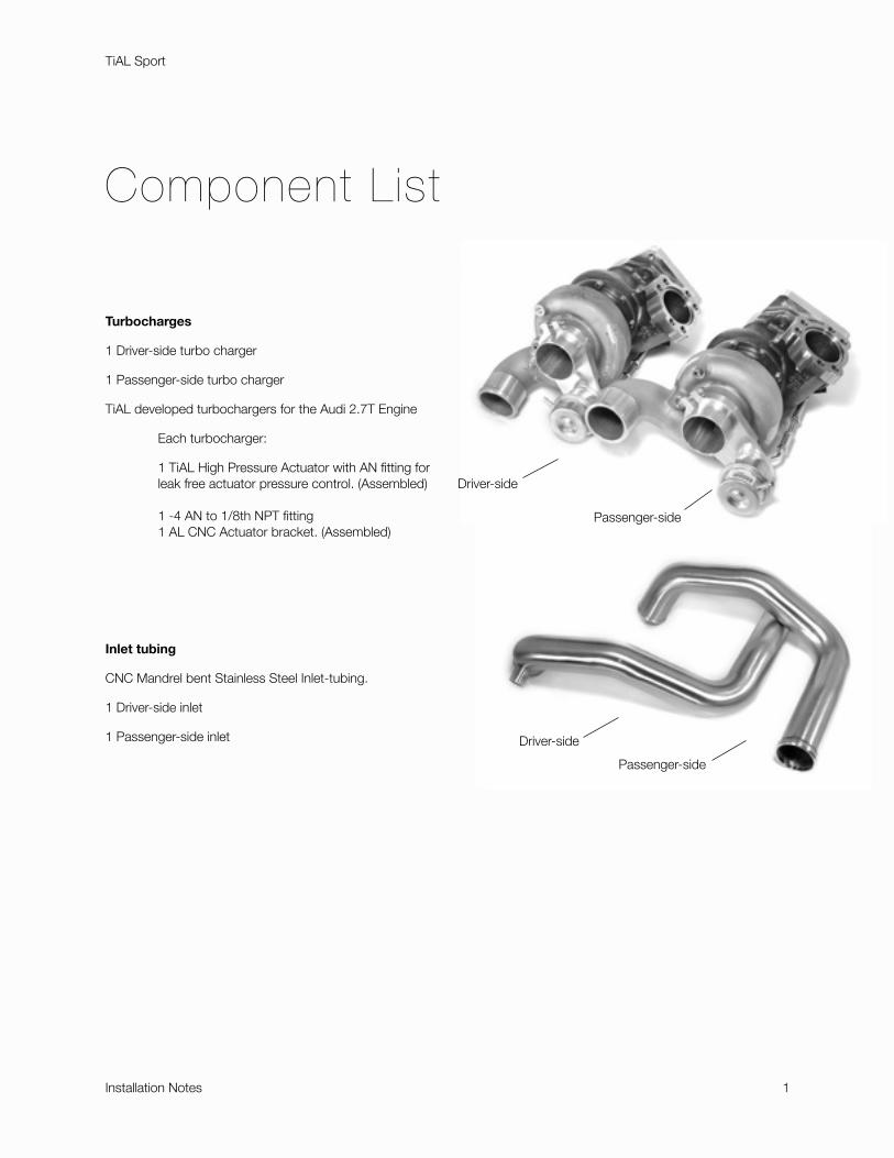
Turbocharges
1 Driver-side turbo charger
1 Passenger-side turbo charger
TiAL developed turbochargers for the Audi 2.7T Engine
! Each turbocharger:
" 1 TiAL High Pressure Actuator with AN fitting for " leak free actuator pressure control. (Assembled)
" 1 -4 AN to 1/8th NPT fitting " 1 AL CNC Actuator bracket. (Assembled)
Inlet tubing
CNC Mandrel bent Stainless Steel Inlet-tubing.
1 Driver-side inlet
1 Passenger-side inlet
TiAL Sport
Installation Notes " 1
Driver-side
Passenger-side
Passenger-side
Driver-side
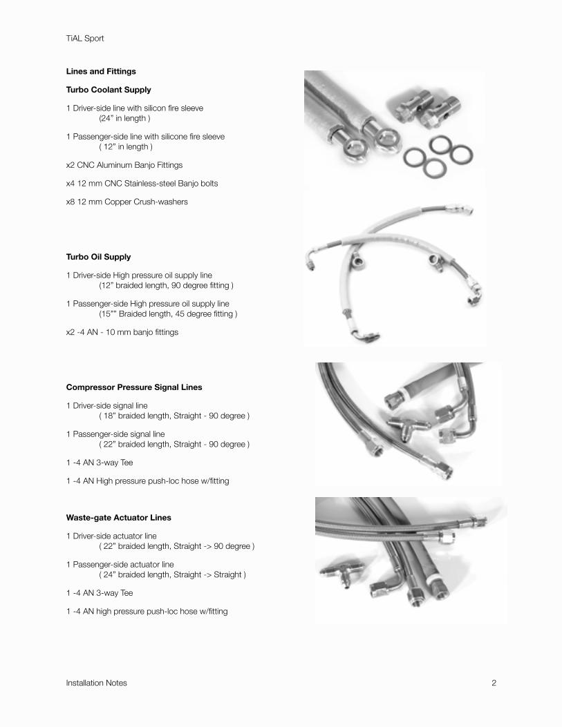
Lines and Fittings
Turbo Coolant Supply
1 Driver-side line with silicon fire sleeve " (24” in length )
1 Passenger-side line with silicone fire sleeve" ( 12” in length )
x2 CNC Aluminum Banjo Fittings !
x4 12 mm CNC Stainless-steel Banjo bolts
x8 12 mm Copper Crush-washers
Turbo Oil Supply
1 Driver-side High pressure oil supply line" (12” braided length, 90 degree fitting )
1 Passenger-side High pressure oil supply line" (15”” Braided length, 45 degree fitting )
x2 -4 AN - 10 mm banjo fittings
Compressor Pressure Signal Lines
1 Driver-side signal line" ( 18” braided length, Straight - 90 degree )
1 Passenger-side signal line" ( 22” braided length, Straight - 90 degree )
1 -4 AN 3-way Tee
1 -4 AN High pressure push-loc hose w/fitting
Waste-gate Actuator Lines
1 Driver-side actuator line" ( 22” braided length, Straight -> 90 degree )
1 Passenger-side actuator line" ( 24” braided length, Straight -> Straight )
1 -4 AN 3-way Tee
1 -4 AN high pressure push-loc hose w/fitting
TiAL Sport
Installation Notes " 2
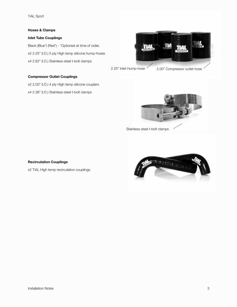
Hoses & Clamps
Inlet Tube Couplings
Black (Blue*) (Red*) - *Optioned at time of order.
x2 2.25” (I.D.) 5 ply High temp silicone hump-hoses
x4 2.62” (I.D.) Stainless-steel t-bolt clamps
Compressor Outlet Couplings
x2 2.00” (I.D.) 4 ply High temp silicone couplers
x4 2.38” (I.D.) Stainless-steel t-bolt clamps
Recirculation Couplings
x2 TiAL High temp recirculation couplings
TiAL Sport
Installation Notes " 3
2.25” Inlet Hump-hose 2.00” Compressor outlet hose
Stainless-steel t-bolt clamps
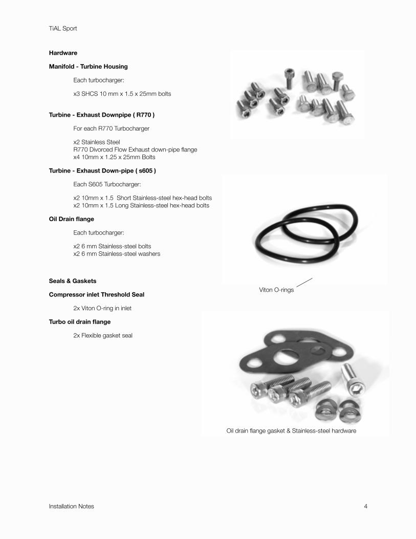
Hardware
Manifold - Turbine Housing
! Each turbocharger:
" x3 SHCS 10 mm x 1.5 x 25mm bolts
Turbine - Exhaust Downpipe ( R770 )
! For each R770 Turbocharger
" x2 Stainless Steel" R770 Divorced Flow Exhaust down-pipe flange" x4 10mm x 1.25 x 25mm Bolts
Turbine - Exhaust Down-pipe ( s605 )
! Each S605 Turbocharger:
" x2 10mm x 1.5 Short Stainless-steel hex-head bolts" x2 10mm x 1.5 Long Stainless-steel hex-head bolts
Oil Drain flange
! Each turbocharger:
" x2 6 mm Stainless-steel bolts" x2 6 mm Stainless-steel washers
Seals & Gaskets
Compressor inlet Threshold Seal
! 2x Viton O-ring in inlet
Turbo oil drain flange
! 2x Flexible gasket seal
TiAL Sport
Installation Notes " 4
Viton O-rings
Oil drain flange gasket & Stainless-steel hardware
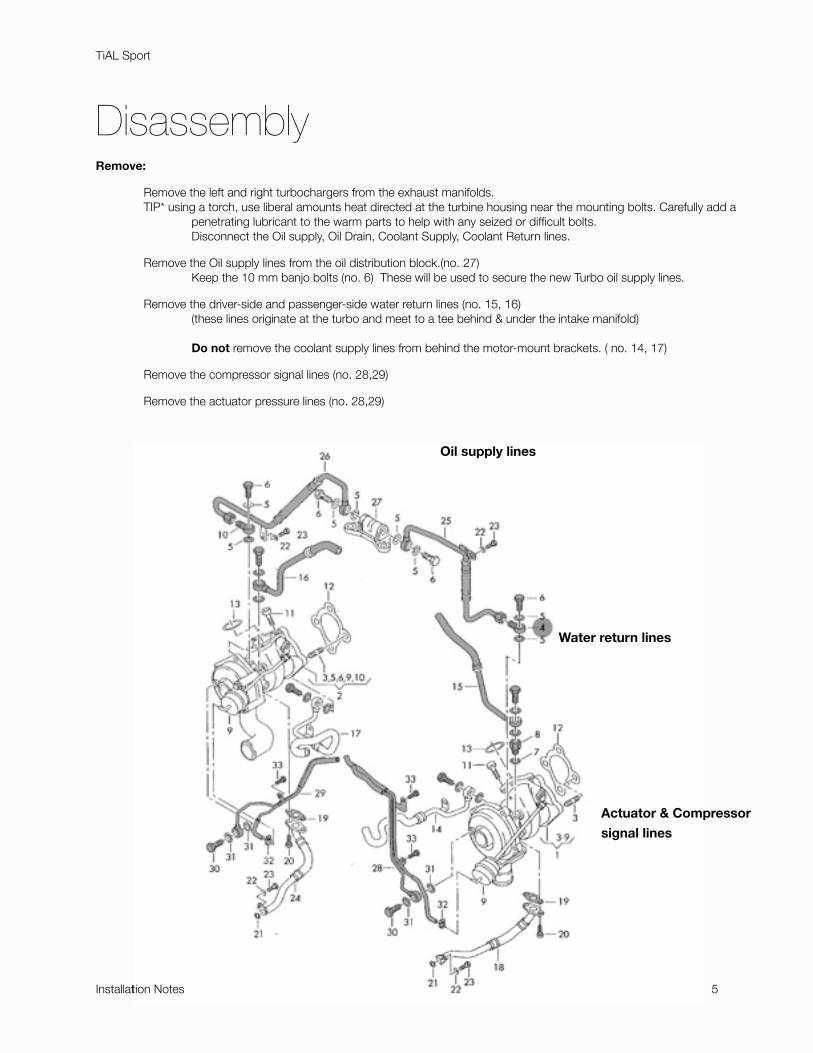
DisassemblyRemove:
" Remove the left and right turbochargers from the exhaust manifolds." TIP* using a torch, use liberal amounts heat directed at the turbine housing near the mounting bolts. Carefully add a " " penetrating lubricant to the warm parts to help with any seized or difficult bolts. " " Disconnect the Oil supply, Oil Drain, Coolant Supply, Coolant Return lines.
" Remove the Oil supply lines from the oil distribution block.(no. 27)" " Keep the 10 mm banjo bolts (no. 6) These will be used to secure the new Turbo oil supply lines.
" Remove the driver-side and passenger-side water return lines (no. 15, 16)" " (these lines originate at the turbo and meet to a tee behind & under the intake manifold)
" " Do not remove the coolant supply lines from behind the motor-mount brackets. ( no. 14, 17)
! Remove the compressor signal lines (no. 28,29)
! Remove the actuator pressure lines (no. 28,29)
TiAL Sport
Installation Notes " 5
Oil supply lines
Water return lines
Actuator & Compressor
signal lines
tion Notes
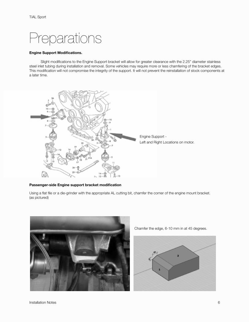
Preparations Engine Support Modifications. " Slight modifications to the Engine Support bracket will allow for greater clearance with the 2.25” diameter stainless steel inlet tubing during installation and removal. Some vehicles may require more or less chamfering of the bracket edges. This modification will not compromise the integrity of the support. It will not prevent the reinstallation of stock components at a later time.
Passenger-side Engine support bracket modification
Using a flat file or a die-grinder with the appropriate AL cutting bit, chamfer the corner of the engine mount bracket.(as pictured)
TiAL Sport
Installation Notes " 6
Engine Support -
Left and Right Locations on motor.
Chamfer the edge, 6-10 mm in at 45 degrees.
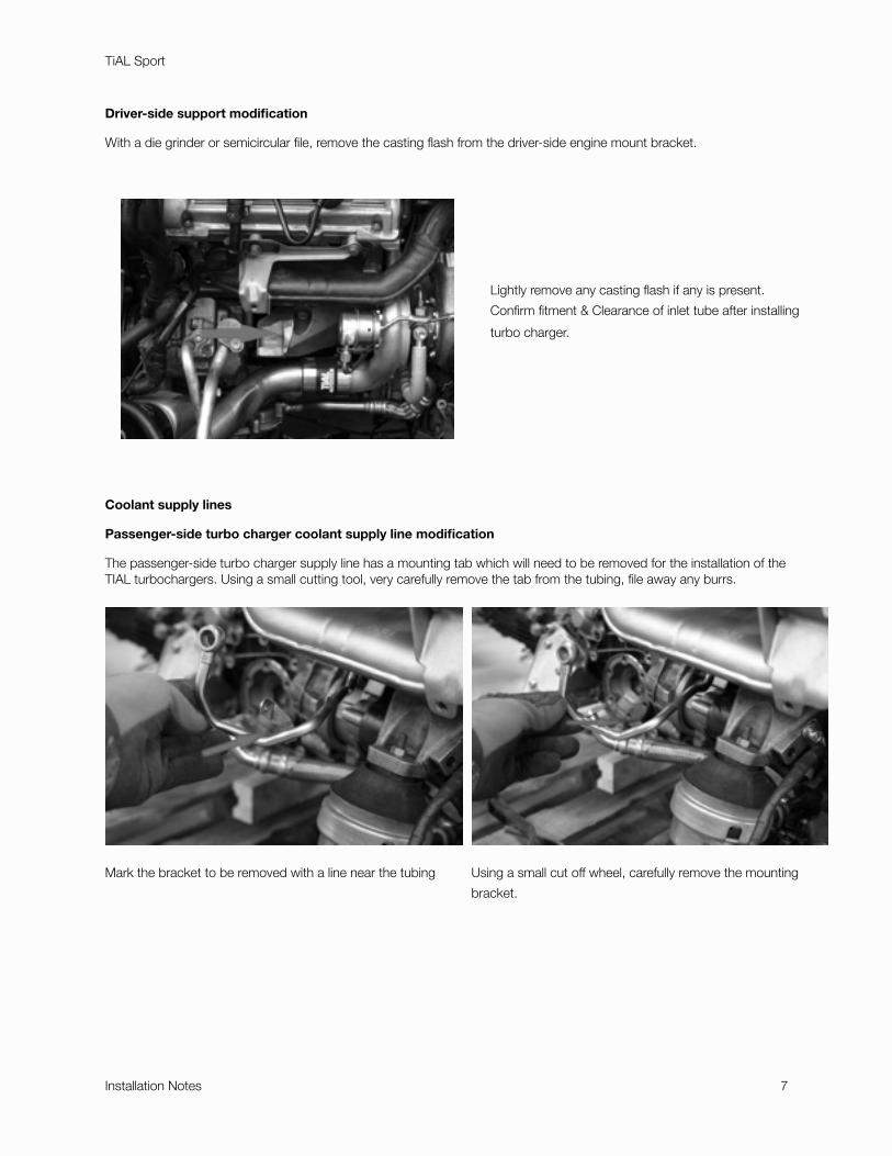
Driver-side support modification
With a die grinder or semicircular file, remove the casting flash from the driver-side engine mount bracket.
Coolant supply lines
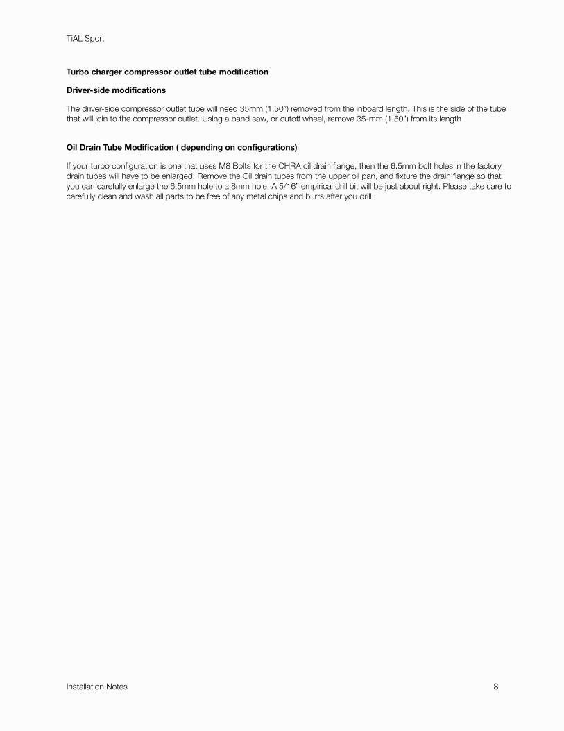
Passenger-side turbo charger coolant supply line modification
The passenger-side turbo charger supply line has a mounting tab which will need to be removed for the installation of the TIAL turbochargers. Using a small cutting tool, very carefully remove the tab from the tubing, file away any burrs.
TiAL Sport
Installation Notes " 7
Lightly remove any casting flash if any is present.
Confirm fitment & Clearance of inlet tube after installing
turbo charger.
Mark the bracket to be removed with a line near the tubing Using a small cut off wheel, carefully remove the mounting
bracket.
Turbo charger compressor outlet tube modification
Driver-side modifications
The driver-side compressor outlet tube will need 35mm (1.50”) removed from the inboard length. This is the side of the tube that will join to the compressor outlet. Using a band saw, or cutoff wheel, remove 35-mm (1.50”) from its length
Oil Drain Tube Modification ( depending on configurations)
If your turbo configuration is one that uses M8 Bolts for the CHRA oil drain flange, then the 6.5mm bolt holes in the factory drain tubes will have to be enlarged. Remove the Oil drain tubes from the upper oil pan, and fixture the drain flange so that you can carefully enlarge the 6.5mm hole to a 8mm hole. A 5/16” empirical drill bit will be just about right. Please take care to carefully clean and wash all parts to be free of any metal chips and burrs after you drill.
TiAL Sport
Installation Notes " 8
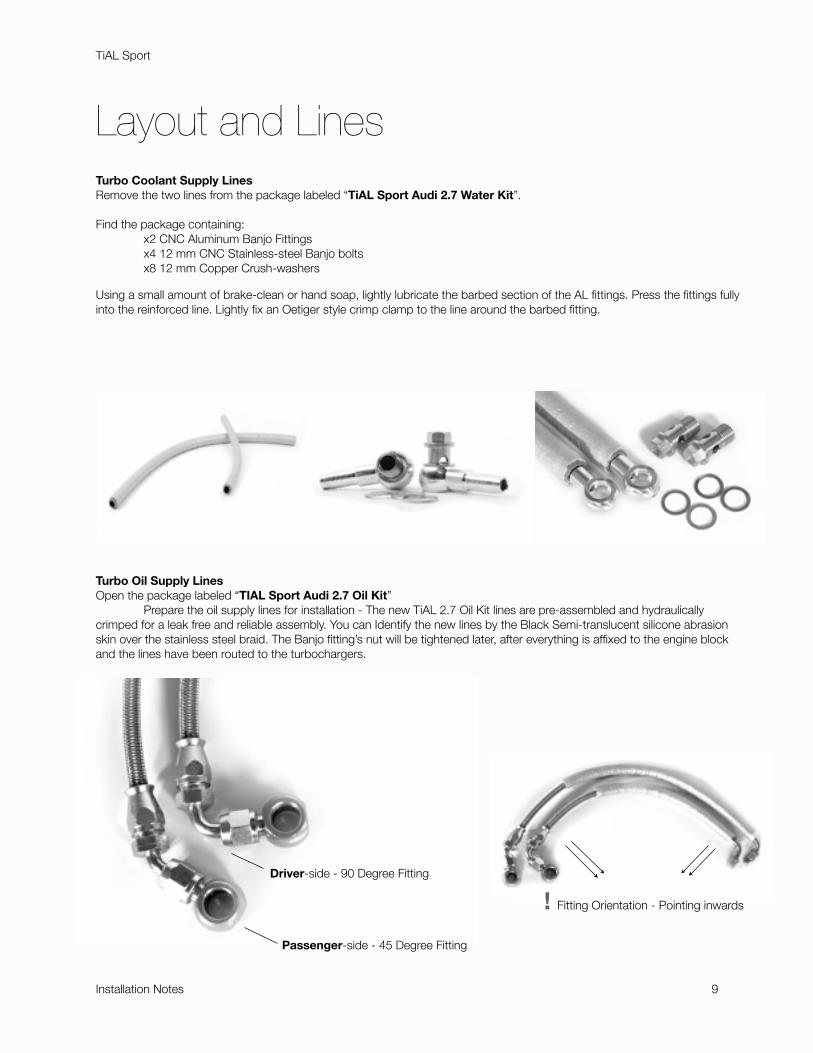
Layout and Lines Turbo Coolant Supply Lines Remove the two lines from the package labeled “TiAL Sport Audi 2.7 Water Kit”.
Find the package containing: ! x2 CNC Aluminum Banjo Fittings " x4 12 mm CNC Stainless-steel Banjo bolts" x8 12 mm Copper Crush-washers
Using a small amount of brake-clean or hand soap, lightly lubricate the barbed section of the AL fittings. Press the fittings fully into the reinforced line. Lightly fix an Oetiger style crimp clamp to the line around the barbed fitting.
Turbo Oil Supply Lines Open the package labeled “TIAL Sport Audi 2.7 Oil Kit” " Prepare the oil supply lines for installation - The new TiAL 2.7 Oil Kit lines are pre-assembled and hydraulically crimped for a leak free and reliable assembly. You can Identify the new lines by the Black Semi-translucent silicone abrasion skin over the stainless steel braid. The Banjo fitting’s nut will be tightened later, after everything is affixed to the engine block and the lines have been routed to the turbochargers.
TiAL Sport
Installation Notes " 9
Passenger-side - 45 Degree Fitting
Driver-side - 90 Degree Fitting
! Fitting Orientation - Pointing inwards
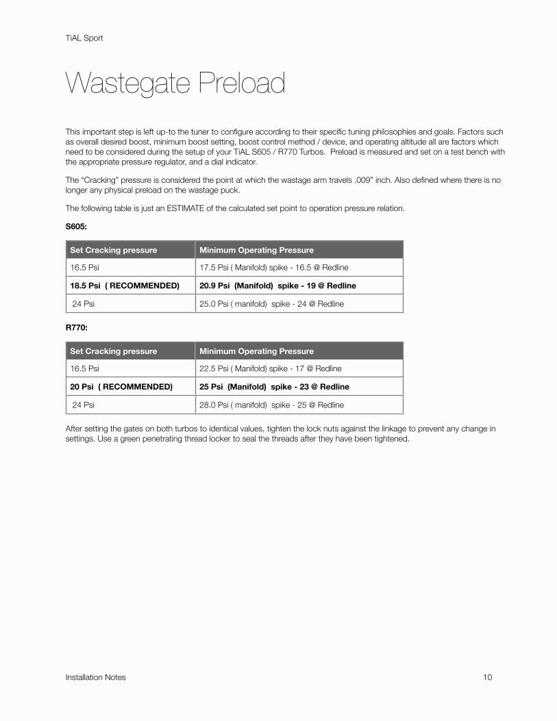
Wastegate Preload
This important step is left up-to the tuner to configure according to their specific tuning philosophies and goals. Factors such as overall desired boost, minimum boost setting, boost control method / device, and operating altitude all are factors which need to be considered during the setup of your TiAL S605 / R770 Turbos. Preload is measured and set on a test bench with the appropriate pressure regulator, and a dial indicator.
The “Cracking” pressure is considered the point at which the wastage arm travels .009” inch. Also defined where there is no longer any physical preload on the wastage puck.
The following table is just an ESTIMATE of the calculated set point to operation pressure relation.
S605:
Set Cracking pressure Minimum Operating Pressure
16.5 Psi 17.5 Psi ( Manifold) spike - 16.5 @ Redline
18.5 Psi ( RECOMMENDED) 20.9 Psi (Manifold) spike - 19 @ Redline
24 Psi 25.0 Psi ( manifold) spike - 24 @ Redline
R770:
Set Cracking pressure Minimum Operating Pressure
16.5 Psi 22.5 Psi ( Manifold) spike - 17 @ Redline
20 Psi ( RECOMMENDED) 25 Psi (Manifold) spike - 23 @ Redline
24 Psi 28.0 Psi ( manifold) spike - 25 @ Redline
After setting the gates on both turbos to identical values, tighten the lock nuts against the linkage to prevent any change in settings. Use a green penetrating thread locker to seal the threads after they have been tightened.
TiAL Sport
Installation Notes " 10
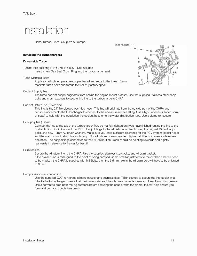
Installation ! Bolts, Turbos, Lines, Couplers & Clamps.
Installing the Turbochargers
Driver-side Turbo
Turbine inlet seal ring ( PN# 078 145 039 ) Not Included" Insert a new Gas Seal Crush Ring into the turbocharger seat.
Turbo-Manifold Bolts" Apply some high temperature copper based anti seize to the three 10 mm " manifold-turbo bolts and torque to 25N-M ( factory spec)
Coolant Supply line" The turbo coolant supply originates from behind the engine mount bracket. Use the supplied Stainless-steel banjo " bolts and crush washers to secure this line to the turbocharger’s CHRA.
Coolant Return line (Driver-side) " This line, is the 24” fire-sleeved push-loc hose. This line will originate from the outside port of the CHRA and " continue underneath the turbocharger to connect to the coolant return tee fitting. Use a light "lubricant ( silicon spray " or soap) to help with the installation the coolant hose onto the water distribution tube. Use a clamp to "secure.
Oil supply line ( Driver)" Connect the line to the top of the turbocharger first, do not fully tighten until you have finished routing the line to the " oil distribution block. Connect the 10mm Banjo fittings to the oil distribution block using the original 10mm Banjo " bolts, and new 10mm AL crush washers. Make sure you leave sufficient clearance for the PCV system (spider hose) " and the main coolant return line and clamp. Once both ends are no routed, tighten all fittings to ensure a leak-free " operation. The banjo fittings connected to the Oil-Distribution-Block should be pointing upwards and slightly " rearwards in reference to the car for best fit.
Oil return line" Secure the oil return line to the CHRA. Use the supplied stainless steel bolts, and oil drain gasket. " If the braided line is misaligned to the point of being crimped, some small adjustments to the oil drain tube will need " to be made. If the CHRA is supplies with M8 Bolts, then the 6.5mm hole in the oil drain port will have to be enlarged " to 8mm.
Compressor outlet connection" Use the supplied 2.00” reinforced silicone coupler and stainless steel T-Bolt clamps to secure the intercooler inlet " tube to the turbocharger. Ensure that the inside surface of the silicone coupler is clean and free of any oil or grease. " Use a solvent to prep both mating surfaces before securing the coupler with the clamp, this will help ensure you " form a strong and trouble free union.
TiAL Sport
Installation Notes " 11
Inlet seal no. 13
Passenger-side
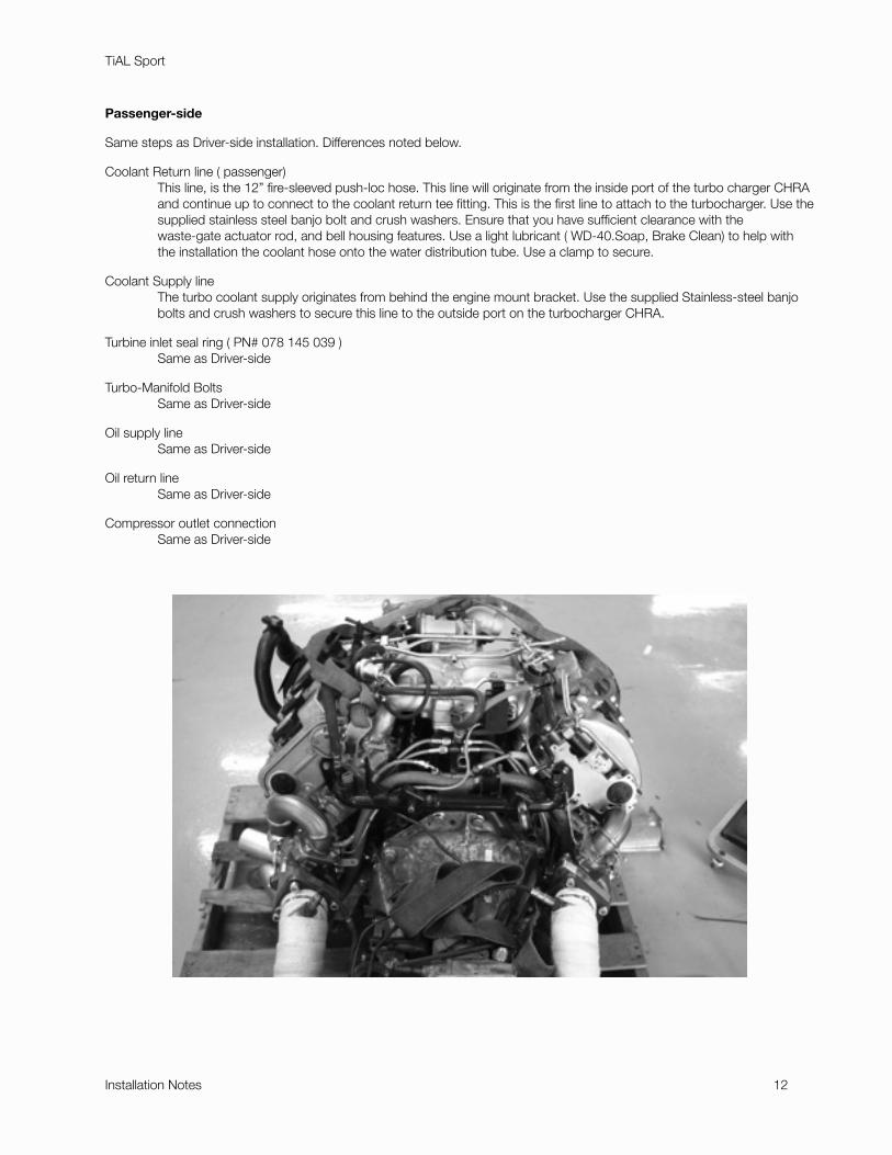
Same steps as Driver-side installation. Differences noted below.
Coolant Return line ( passenger) " This line, is the 12” fire-sleeved push-loc hose. This line will originate from the inside port of the turbo charger CHRA " and continue up to connect to the coolant return tee fitting. This is the first line to attach to the turbocharger. Use the " supplied stainless steel banjo bolt and crush washers. Ensure that you have sufficient clearance with the " waste-gate actuator rod, and bell housing features. Use a light lubricant ( WD-40.Soap, Brake Clean) to help with " the installation the coolant hose onto the water distribution tube. Use a clamp to secure.
Coolant Supply line" The turbo coolant supply originates from behind the engine mount bracket. Use the supplied Stainless-steel banjo " bolts and crush washers to secure this line to the outside port on the turbocharger CHRA.
Turbine inlet seal ring ( PN# 078 145 039 )" Same as Driver-side
Turbo-Manifold Bolts" Same as Driver-side
Oil supply line" Same as Driver-side
Oil return line" Same as Driver-side
Compressor outlet connection" Same as Driver-side
TiAL Sport
Installation Notes " 12
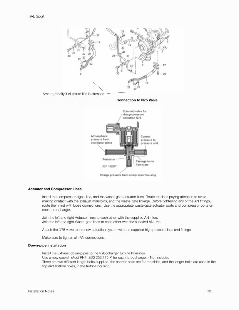
Connection to N75 Valve"
Actuator and Compressor Lines
! Install the compressor signal line, and the waste-gate actuator lines. Route the lines paying attention to avoid ! making contact with the exhaust manifolds, and the waste-gate linkage. Before tightening any of the AN fittings, ! route them first with loose connections. Use the appropriate waste-gate actuator ports and compressor ports on ! each turbocharger.
" Join the left and right Actuator lines to each other with the supplied AN - tee." Join the left and right Waste-gate lines to each other with the supplied AN -tee.
! Attach the N75 valve to the new actuation system with the supplied high pressure lines and fittings.
! Make sure to tighten all -AN connections.
Down-pipe installation
" Install the Exhaust down-pipes to the turbocharger turbine housings." Use a new gasket. (Audi PN#: 8D0 253 115 F) for each turbocharger. - Not Included" There are two different length bolts supplied, the shorter bolts are for the sides, and the longer bolts are used in the " top and bottom holes, in the turbine housing.
TiAL Sport
Installation Notes " 13
Area to modify if oil return line is stressed.
Inlet-pipe installation.
! Before placing the motor into the vehicle, ensure that you can install and remove the inlet tubes from the compressor ! inlet. Prepare the two Viton rings, by lubricating them with a thick lubricant or grease. Press them into the threshold ! grove of the inlet tube. Use your fingers to ensure that the O-ring is FULLY seated into the grove before ! attempting to press it onto the compressor inlet. The initial installation might require some force.
" Use the supplied 2.25” Hump hoses to connect the OEM Y-Pipe to the stainless steel inlet tubes. Secure the " coupling with the supplied stainless-steel t-bolt clamps You do not need to torque this connection much beyond " finger tight, as it is not part of the pressurized charge path.
! *! IF you are attempting to install the Inlet tubes after you place the engine back into the engine bay. You will need to ! lift the motor 3-4 inches from its final position. The motor mount nuts will have to be removed to allow for this ! upward travel. The Tubes will be able to be inserted as they will now clear the frame rails, allowing you to push the ! tubes in as you rotate them into place.
" *! For customers with an RS4 Y-pipe. The Correct coupler will be a 2.75-2.225 transition coupler. In addition 0.75” " will need to be removed from the top end of each inlet pipe. Please contact us for the correct silicone part.
Recirculation BBV’s
" With the Inlet pipes installed, use the 1” silicone elbows to connect to the recirculation circuit.
" *! An X-1 or other intake system is required for proper fitment. Otherwise modification to airbox will need to be " made.
TiAL Sport
Installation Notes " 14