throughput of wireless-powered massive distributed antenna ... · throughput of wireless-powered...
TRANSCRIPT
Throughput of Wireless-Powered Massive Distributed
Antenna Systems Over Composite Fading Channels
Qing Wang1,2
, Hailiang Xiong2, Shanshan Yu
2, and Yuxi Liu
3
1 State Grid Shandong Electric Power Research Institute, Jinan, 250003, China
2 School of Information Science and Engineering, Shandong University, Jinan, 250100, China 3 State Grid Information and Telecommunication Group Co., Ltd., Beijing, 100192, China
Email: [email protected]; {hailiangxiong, shanshanyu}@sdu.edu.cn; [email protected]
Abstract—Massive Distributed Antenna System (DAS) with
energy harvesting can promisingly satisfy the ever-growing
wireless transmission requirements while providing sustainable
power supply to the User Equipment (UE). In this paper, we
propose a massive DAS with multiple-circle layout, where a
large number of Remote Antenna Units (RAUs) are evenly
distributed across these circles. Based on the instantaneous
channel quality, a RAU is selected for the downlink wireless
energy transfer to the UE. Using the harvested energy, the UE
transmits information to all the RAUs according to the “harvest-
then-transmit” protocol over the uplink. The closed-form
asymptotic throughput for an arbitrary UE is derived over
composite fading channels, which include the shadowing,
fading, and path-loss effects. Subsequently, we analyze the
average throughput when the UEs are uniformly distributed in
the cell. Performance results are provided to validate our
theoretical analysis and reveal the impacts of time allocation,
UE locations, and RAU deployment on the system throughput. Index Terms—Massive distributed antenna system, remote
antenna unit, throughput, wireless energy transfer, wireless
information transmission
I. INTRODUCTION
The fifth-generation (5G) mobile communications
systems are expected to satisfy the rapid growth of
various wireless services by enhancing the spectral and
energy efficiencies [1], [2]. However, since the user
equipments (UEs) operate with the capacity-limited
batteries, mobile networks cannot realize unstoppable
communications [3], [4]. To extend the lifetime of mobile
networks, scholars have proposed Energy Harvesting (EH)
or Wireless Energy Transfer (WET) technique by
enabling the UEs to harvest the ambient Radio Frequency
(RF) energy [5], [6]. Nevertheless, the efficiency of WET
is low because of the severe path-loss caused by the long
distance between transmitters and receivers [7]-[9].
Massive Multiple-Input Multiple-Output (MIMO)
technique has been commonly regarded as a promising
technique for enhancing the energy efficiency and
spectral efficiency by deploying hundreds of antennas at
Manuscript received July 17, 2016; revised January 20, 2017. This work was supported by the Natural Science Foundation of
China under Grant No. 61401253. Corresponding author email: [email protected]
doi:10.12720/jcm.12.1.24-31
a Central Base Station (CBS) [10]. Beamforming and EH
zone have been further used to improve the EH efficiency
in massive MIMO and cognitive radio networks,
respectively [11], [12]. In general, only the receivers with
short distance to the transmitters may harvest sufficient
energy for the Wireless Information Transfer (WIT).
As a counterpart of the centralized massive MIMO,
massive Distributed Antenna System (DAS) is a potential
network to overcome the boundary effect and guarantee
the communications fairness of UEs with different
locations [13]. Compared with the traditional DAS in
which a few Remote Antenna Units (RAUs) are
distributed in a cell [14], [15], massive DAS contains
hundreds of RAUs which are connected to the Baseband
Processor Unit (BPU) via optical fiber. The effects of
small-scale fading and the uncorrelated noise can be
alleviated in massive DAS with this configuration [16].
Compared with the centralized massive MIMO, massive
DAS can achieve the macro-diversity with such flexible
structure [17]. The average distance between transmitters
and receivers can be shortened in this structure, which
can weaken the path-loss and reduce the transmit power
[18]. Therefore, it is more feasible to implement the WET
in massive DAS. Reference [17] proposed a massive
DAS model based on single-circle layout, and the optimal
radius of RAU deployment was acquired through
maximizing the asymptotic data rate. Li et al. investigated
the massive DAS based on multiple-antenna clusters
layout, and each cluster equips multiple antennas [19],
[20]. The authors of [13] and [16] proposed a massive
DAS model with uniformly distributed RAUs, and the
average distance between transceivers can be shortened.
Unfortunately, these models are either inefficient for the
UEs far away from the RAUs to harvest the RF energy
nor too complicated in connecting all the RAUs via
optical fiber. Therefore, it is desirable to design a feasible
massive DAS for simultaneously WET and WIT with less
optical fiber. Since the WET technique is sensitive to the
distance between transceivers, how to improve the EH
efficiency is another urgent issue. One effective approach
is to select a suitable RAU for the WET towards the UE,
which can reduce the RF chains cost and enhance the EH
efficiency [21]. Practically, various RAU selection
schemes for the WIT can be also applied to the wireless-
power based massive DAS [14]-[24].
Journal of Communications Vol. 12, No. 1, January 2017
©2017 Journal of Communications 24
In this paper, we study the massive DAS with
multiple-circle layout based on the EH over composite
fading channels which include the shadowing, small-scale
fading, and path-loss effects. We first propose a circular
architecture for the massive DAS, where hundreds of
RAUs are deployed over multiple circles. On one hand,
this model can shorten the WET distance between RAU
and UE. On the other hand, with this circular layout
pattern, it is easier to connect RAUs using optical
backhaul. To save the signaling overhead and improve
the EH efficiency, the RAU with the best channel quality
towards the UE is selected for the downlink WET. In
addition, the closed-form asymptotic throughput for an
arbitrary UE is derived with no shadowing and
shadowing. The average throughput for a typical UE in
the cell is also developed from the design perspective.
Performance results are provided to validate our
theoretical analysis and show the impacts of various
parameters on the throughput performance, which can
provide some guidelines for the network deployment.
The reminder of this paper is organized as follows.
Section II introduces the wireless-powered massive DAS
with multiple-circle layout. In Section III, we analyze the
asymptotic throughput of the RAU selection WET based
on the best channel quality. Numerical and simulation
results are provided in Section IV. Finally, Section V
concludes this paper.
Notation: Boldface lowercase and uppercase letters
represent vectors and matrices, respectively. | | denotes
the absolute value, {}E denotes the expectation, {}Pr
denotes the probability, tr( ) denotes the trace of a matrix,
and F
denotes the Frobenius norm of a vector. The
operations T( ) and H( ) represent the transpose and
conjugate transpose of a vector, respectively. ( )nm is
given as ( 1)
( )( 1) ( 1)
n
mm
n m n
, where n and m are
integers, and m k represents ( )1
1 1( 1)
mM Mm
m
.
II. SYSTEM MODEL
We consider a wireless-powered massive DAS over
composite fading channels, where the energy is harvested
in the downlink and the information is transferred in the
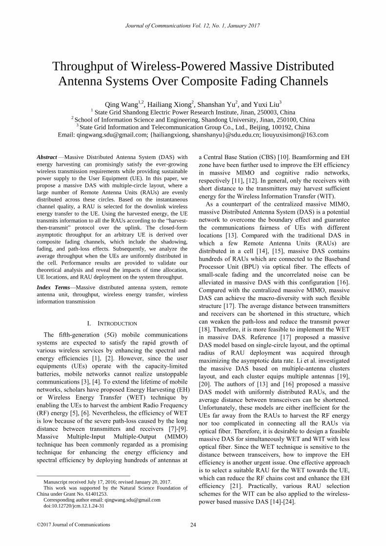
uplink. As shown in Fig. 1, dozens or hundreds of RAUs
are evenly distributed across N circles, and they are all
connected to a BPU via optical fiber. The BPU processes
signals in a centralized way. Compared with stochastic
layout and regular-grid layout, this architecture needs less
optical backhaul connection, which can simplify the
performance analysis as the topology is equivalent to one
dimensional network. Throughout this paper, the Time
Division Multiple Access (TDMA) technique is applied
in each time block, and the Channel State Information
(CSI) of both uplink and downlink is assumed to be
available at the RAU. Further, the signals are assumed to
experience frequency nonselective fading. Since the zero-
forcing decoder can separate data from different UEs, the
interference among UEs diminishes in massive MIMO
with such a large number of antennas [17]. In this work,
to facilitate the analysis, we consider the single user
scenario, while we intend to study the multi-user scenario
in future work.
rO
R
O
Dn,k
do
d2,1
,n k
Fig. 1. The system model of wireless-powered massive DAS. In this
figure, Y denotes RAU, X denotes UE, the diamond represents the BPU, and the dashed line represents the optical backhaul.
The total number of RAUs in a cell is set to be M .
The mth RAU deployed in a cell is denoted asmR , where
1 m M . Each UE and RAU is equipped with one
omnidirectional antenna. The downlink and the uplink
small-scale fading between the lth RAU and the UE is
denoted as mh and
mg , respectively. The harvest-then-
transmit protocol is adopted in the downlink, where in the
first 0 (
00 1 ) time, the UE harvests the RF energy
from the selected RAU and saves the energy into battery.
In the remaining 01 time, the UE transmits
information data to the RAUs using the harvested energy.
A. Downlink Energy Transfer
In the downlink phase, the optimal RAU, oR , is
selected to transfer the wireless energy to the UE. The
baseband signal transmitted by the mth RAU,mR , is
denoted as ms satisfying 2{| | } 1ms E , the downlink path-
loss can be modeled as m mL d
, where md is the
distance between mR and the UE, and is the path-loss
exponent. The shadowing from each RAU is
independently and identically distributed. In a given time
block, the received signal from the selected RAU at the
UE is expressed as
o s t o o o or S PL h s n (1)
where tP is the transmit power of RAU,
on is the additive
white Gaussian noise, and sS characterizes the lognormal
shadowing with the Probability Density Function (PDF)
2
2
10lg( ) exp
22sS
sf s
s
, (2)
Journal of Communications Vol. 12, No. 1, January 2017
©2017 Journal of Communications 25

where 10 / ln10 , and (in dB) are the mean and
the standard deviation of 10lg s , respectively. It is noted
that when 1sS , there is no shadowing during the
transmission.
Since the transmit power tP is sufficiently large, the
energy harvested from the noise is negligible. The
amount of energy harvested by UE is given by
2
0 | |s t ooQ S PL h (3)
where 0 1 denotes the EH efficiency.
B. Uplink Data Transmission
In the remaining time fraction, the UE sends its data
with its achievable rate to the RAUs. The uplink path-loss
is denoted as mL due to the symmetry of the propagation
path between uplink and downlink. As the uplink channel
fading related to mR is
mg , the 1M channel vector
between UE and RAUs can be written as
T
1 1s Ms MS L g S L g
c (4)
We define mx as the transmitted signal from the UE to
the mth RAU with 2{| | } 1mx E . The received signal at
the BPU can be obtained as
1
M
m m ms a
m
y S P L g x n
(5)
Since the energy harvested in the downlink is used for
the circuit operation and information transmission, we
define 0 1 as the proportion of energy used for the
information transmission. Then, the available transmit
power for the UE is
2
0
0 0
| |
1 1
s t o o
a
S PL hQP
. (6)
It is observed from (4) and (5) that the instantaneous
SNR at the BPU is given as
22
02
2
0
| |
(1 )
s t o oS P L h
c. (7)
III. THROUGHPUT ANALYSIS
In this section, we analyze the throughput of massive
DAS over composite fading channels. For the downlink,
the RAU with the best channel quality towards the UE is
selected for the WET to reduce the signaling overhead
and the RF-chain cost. For the uplink, the UE transmits
data to all the RAUs simultaneously to fulfill the macro-
diversity.
A. RAU Selection for the WET
The RAU with the best channel quality towards the UE
is selected for the WET, i.e.,
1
arg maxom
mM
(8)
where
2
2
s m m
m
tS PL h
.
As mh is Rayleigh distributed,
m follows the
exponential distribution and its Cumulative Distribution
Function (CDF) conditioned on the given sS can be
written as
| ( ) 1 expm sS mF (9)
where 2
s t
m
m mS PL
and 2{| | }m mE h .
Based on (9), the conditional CDF of o is given as
|
1
( ) 1 exp ,o s
M
S m
m
F
(10)
where all the RAUs are independently distributed in the
cell.
We denote ,mF as the th m-subset of
iF that
contains m elements, where 1,2,...( )mM . The
elements of ,mF are denoted as , ,m l ( 1,2,...,l m ),
which are related with2
s t
m
m mS PL
. According to (19)
of [25], (19) can be rewritten as
, ,
1
( )
1
| , ,
1 11
( ) 1 ( 1) exp
1 ,
m
o s
m
m l
l
M mMm
S m l
m l
m
F
e
(11)
The conditional PDF of o can be obtained by taking
the derivative of (11) as
, ,
1
| , ,
1
( )
m
m l
l
o s
m
S m l
m l
f e
(12)
B. Throughput of Massive DAS
Theorem 1: As M , the asymptotic ergodic
capacity conditioned on the downlink channel fading, oh ,
without considering the shadowing effect can be given by
2 0
2
0
log 1 | | ,1
o
NS
h t o oC PML h L
(13)
where 2
. In (13), when the number of RAUs tends
to be infinity, the average path-loss is given as
1
1lim .
M
mM
m
L LM
(14)
Proof: Conditioned on the downlink channel fading
with no shadowing, the ergodic capacity is given as
Journal of Communications Vol. 12, No. 1, January 2017
©2017 Journal of Communications 26
0 2
2
20
2 2
0
log 1
| |log 1 .
1
NS
h
o o
t
C
L hP
E
E c‖‖ (15)
We define T
1 2[ ]Mg g g g as a 1M vector. Let
/ Mg be a random vector of i.i.d. entries with zero
mean and variance1/ M . The eighth-order moment of the
mth fading is expressed as 8 4{| | }/mg ME and its order is
4(1/ )M . Let 1 2diag{ , ,..., }ML L LL be a M M
diagonal matrix which is independent of / Mg .
According to Lemma 4 of [26], when M is sufficiently
large, we have
2
21
H
1 1
1 1 1tr
0.
M
m
m
LM M
MM M
c
g L g L (16)
Therefore, when M ,
2
2
1
.M
m
m
M M L L
c‖‖ (17)
Substituting (17) to (15), we can obtain the asymptotic
ergodic capacity, as shown in (13).
It is also concluded from (13) that if more time is
allocated to the WET, better achievable rate can be
obtained. However, if less time is allocated to the
information transmission, the throughput gets worse.
Hence, there exists a time-allocation tradeoff between the
downlink WET and the uplink WIT.
1) Without shadowing
When the number of RAUs grows to be infinity,
without shadowing, the system throughput can be derived
as
, ,
1
0
2 |0
0
0 ,
0
0
,
1
0
20
0
log 1 ( )d1
(1 )
log 1
1
d
( )
(1
1
)
oo
o s
m
m l
l
NS
h
NS
h
S
m
m l
m l
C
MLf
MLe
T
E
0 1exp ,
ln 2 m
Ei
(18)
where ( ) / dt
xEi x e t t
is the exponential integral
function [27], and 0
, ,
10
1 m
m l
lML
.
2) With shadowing
Let sS
, when the number of RAUs tends to be
infinity, applying the Gauss Hermite quadrature
integration [28], we can obtain the approximate
throughput as
0
0
2
2
0 2
0
1
1
( 1) 1exp
2 ln 2
10lgexp d
2
1[ ( )]
2 ln 2
exp ,
ds
j
S N
S
S
m
N
j
m j
T T
Eis
ss
t
E
f s s
i
(19)
where 0
, ,
10
1( )
m
m l j
l
tML
, ( )jt
2
510jt
, jH is
a weight factor, jN is the Hermite polynomial order, and
jt is the base point.
Intuitively, the throughput gets better with the increase
of antenna number. However, for the wireless-powered
massive DAS, signals will experience bidirectional path-
loss, and the channel gain related to those RAUs far away
from the UE can be ignored. As a result, the throughput
improves slightly as the number of RAUs increases.
C. Average Throughput of a Typical UE
It is highly challenging to determine the optimal
network design and the best time allocation for the
downlink WET and the uplink WIT to maximize the
average throughput with a large number of RAUs in a
cell. However, this issue is tractable with theoretical
analysis and numerical results.
It is assumed that M RAUs are evenly distributed
across N circles with radius r, 2r, ..., Nr. Since the radius
of each circle is increased by r from the inner ring to the
outer ring, the corresponding numbers of RAUs deployed
on each circle are set as K, 2K, ..., and NK, respectively.
The total number of RAUs in the cell with radius R
is (1 ) / 2M KN N . The kth RAU deployed on the nth
circle is denoted by ,n kR , where 1 k K and
1 n N .The distance between a typical UE and the cell
center is denoted as 0d , the distance between the UE to
the kth RAU on the nth circle, ,n kR , is denoted as ,n kd .
With this circular pattern layout, the angle between any
two adjacent RAUs on the nth circle is assumed to
be2
nnK
. Hence, the adjacent RAUs on each circle
keep the same distance from each other, and the total
number of RAUs in the cell is(1 )
2
KN NM
. The
angle between the direction of the UE to the cell center
Journal of Communications Vol. 12, No. 1, January 2017
©2017 Journal of Communications 27
and ,n kR to the cell center is
,n k . Without loss of
generality, we assume1,1 0 , therefore,
,
2 ( 1)n k
k
nK
.
The distance between the UE and ,n kR is given as
2 2
, 0 0 ,( ) 2 cos .n k n kd nr d nrd (20)
According to (34) of [17], when M , the average
propagation path-loss can be derived as
,
1
1
2 2 20 0 ,
1
2 2 20 0
2 2 20
1
2 2
0
2 21
02
2
( 1)
2 1
( 1)
( ) 2 cos
2
( 1)
( ) 2 cos d
2| ( ) |
( 1)
( ),
| ( ) |
N nK
n k
n k n
N
n
nK
n k
k n
N
n
N
n
L LKN N
KN N
nr d nrd
KnKN N
nr d nrd
n nr dN N
nr dP
nr d
(21)
where ( )P is the Legendre function [29].
Since the UE is uniformly distributed in the cell, the
PDF of the UE's position can be written as [30]
0
0
0 02
2( ) ,0 .d
df d d R
R (22)
Applying (20) and (21) into (18) and (20), and
averaging over the PDF of 0d shown in (22), the
asymptotic average throughput of a cell with no
shadowing is derived as
0 0 02 0
2) . ( d
RNS NS
T d T d dR
(23)
Similarly, the asymptotic average throughput of a cell
with shadowing is given as
0 0 02 0
2( )d .
RS S
T d T d dR
(24)
Since the mathematical tools such as Matlab include
integral and Legendre functions, the analytical
expressions of (23) and (24) can be efficiently evaluated.
The optimal deployment of RAUs, as well as the best
time allocation for the downlink EH and the uplink WIT
can be estimated from the analysis.
IV. NUMERICAL RESULTS
In this section, we present numerical results to
demonstrate the throughput of wireless-powered massive
DAS, and give simulation results to verify the theoretical
results. In the simulations, without stated otherwise, the
cellular radius is set as 500R meters, the number of
circles is N, each circle has K RAUs, the total number of
RAUs is (1 )
2
KN NM
, the path-loss exponent is
3 , the EH efficiency is 0.9 , the proportion of
energy used for the information transmission is 0.9 ,
the normalized time fraction is 0 0.45 , the transmit
power of each RAU is 0.3tP W, the power of noise is
2 80 dBm, and the angles between the direction of
UE to the cell center and horizontal direction is
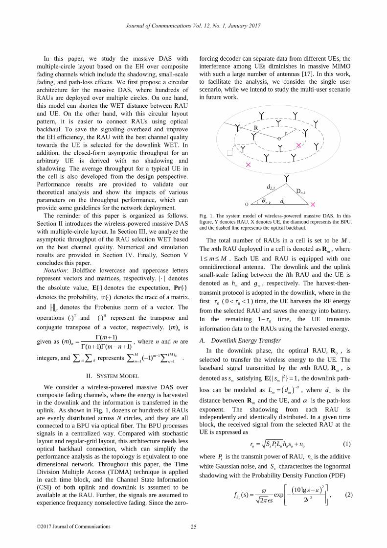
/100 . Fig. 2 depicts the throughput versus the
normalized time fraction allocated to the downlink WET
for the UE at different locations in the cell (N=15 and
M=120) without considering shadowing effect. The
theoretical results shown in (18) agree well with the
simulation results. When 0 0 , i.e., there is no time
allocated to the WET, the throughput is zero. On the
contrary, when 0 1 , i.e., the time allocated to the WIT
is zero. Although the optimal time fraction maximizing
the throughput varies across different UEs' locations, the
throughput increases as more time allocated to the WET,
but it decreases after reaching a peak. This is because the
available transmit power of a UE increases if more time
is allocated to the downlink WET, whereas if 0 exceeds
a threshold, the amount of time for information
transmission decreases. As a result, the gain caused by
WET does not surpass the loss brought by WIT.
0 0.2 0.4 0.6 0.8 10
1
2
3
4
5
6
Normalized time fraction, 0
Thro
ughput
(bps/H
z)
d
0=500 m
d0=330 m
d0=200 m
d0=10 m
Simulation
Fig. 2. Throughput versus normalized time fraction for a UE at different
positions (N=15).
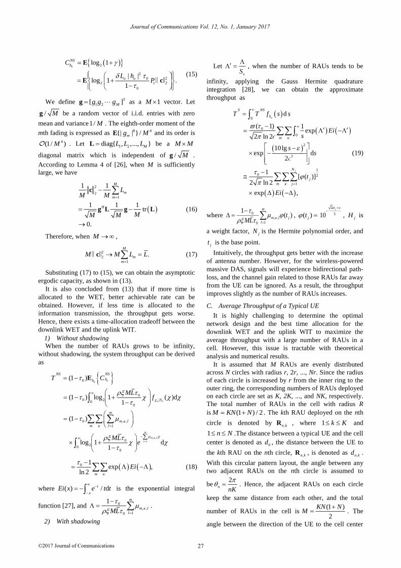
Fig. 3 compares the performance of our proposed RAU
selection scheme and the minimized distance (MD) based
RAU selection scheme. Both the theoretical results of (18)
and (20) with no shadowing and shadowing ( 0 dB,
5 dB) match the simulation results. The throughput of
all the scenarios can reach a peak value when the UE is
located at 0 31.25d m. This is because the radius of the
first inner circle is 31.25r m, and when the UE moves
to this position a RAU deployed in the circle dominates
the performance. Our RAU selection scheme outperforms
Journal of Communications Vol. 12, No. 1, January 2017
©2017 Journal of Communications 28

the minimized distance based RAU selection scheme,
especially when the UE departs far away from the circle.
When more RAUs (M=480) are deployed in the cell, the
throughput increases slightly.
0 5 10 15 20 25 30 35
0
5
10
15
20
25
30
35
40
Distance (m)
Thro
ughput
(bps/H
z)
No Shadowing,BCQ,M=480
No Shadowing,BCQ,M=120
Simulation, no Shadowing,MPL,M=120
Shadowing,BCQ,M=120
Simlulation
16 18 20
2
4
6
Fig. 3. Throughput versus distance for massive DAS with 15-circle links.
0 100 200 300 400 500
-10
0
10
20
30
40
Distance (m)
Thro
ughput
(bps/H
z)
85 90 95 100
10
15
No Shadowing,N=10
Shadowing,N=10
No shadowing,N=20
Shadowing,N=20
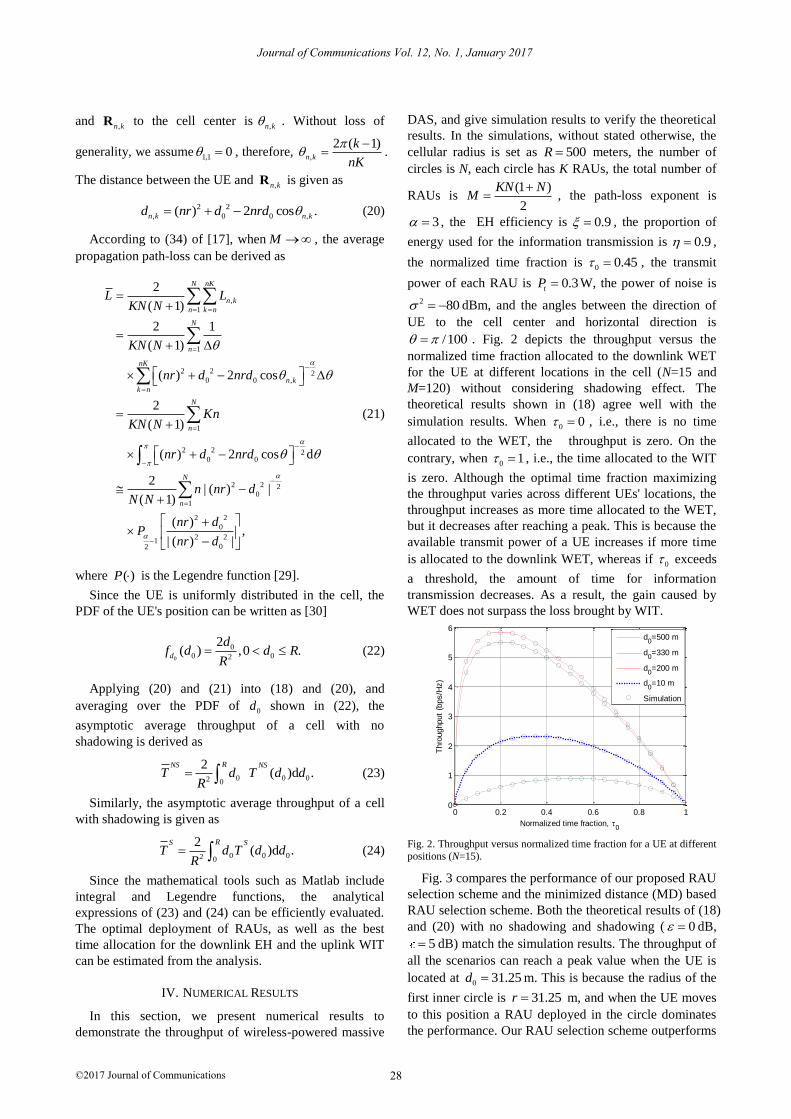
Fig. 4. Throughput versus distance for an arbitrary UE with different
deployment (N=20 and N=10).
Since the theoretical results are verified very tight to
the simulation results, the system performance can be
estimated efficiently by the theoretical expressions
without resorting to the time-consuming simulations. Fig.
4 plots the throughput for an arbitrary UE in a cell based
on 10-circle layout and 20-circle layout. Both the two
deployments have nearly the same number of RAUs
(M=220 for N=10, and M=210 for N=20). The throughput
of the two deployments appears ten and twenty times
peak values around their circles, respectively. The worst
throughput is obtained when the UE is located at the
midway two adjacent circles.
We further study the massive DAS with 10-circle
layout to investigate the impacts of RAU number on the
throughput, and compare our massive DAS with the
centralized large-scale MIMO (L-MIMO) system at
different locations (0 25d m and
0 100d m). Fig. 5
shows that the throughput increases with the number of
antennas, but it grows slowly when the number of
antennas tends to be infinity. Compared with our massive
DAS, the centralized L-MIMO system is more sensitive
to the UE's locations. For instance, when the UE is
located near the cell center ( 0 25d m), the L-MIMO
system outperforms the massive DAS, whereas when the
UE departs far away from the cell center (0 10d m), the
L-MIMO achieves low throughput. Therefore, compared
with the centralized L-MIMO, massive DAS is more
applicable for EH to ensure the fairness of the UEs.
200 400 600 800 1000 1200 14000
2
4
6
8
10
12
14
16
18
Number of Antennas, M
Thro
ughput
(bps/H
z)
Centralized L-MIMO,d
0=25m
Massive DAS,d0=25m
Centralized L-MIMO,d0=100m
Massive DAS,d0=100m
Fig. 5. Throughput versus the number of antennas for massive DAS
with 10-circle and centralized L-MIMO (0 0.2 ).
0 0.1 0.2 0.3 0.4 0.5 0.6 0.70
2
4
6
8
10
12
14
Normalized time fraction, 0
Avera
ge t
hro
ughput
(bps/H
z)
No shadowing
Shadowing
Simulation
Optimal 0*
N=10
N=14
N=20
Fig. 6. Average throughput versus the time fraction with different
number of circle links.
For a typical UE, the average throughput in a cell
reflects the average experience of service. The theoretical
results with no shadowing and shadowing are consistent
with the simulation results. As can be seen from Fig. 6,
the average throughput has the same variation trend as
Fig. 2, and the optimal time fraction that can maximize
the average throughput varies with different number of
circles. For example, the optimal time fractions for
massive DAS with 10-circle layout (M=220), 14-circle
layout (M=210), and 20-circle layout (M=210) are 0.14,
0.12, and 0.1, respectively. It is concluded from Fig. 5
and Fig. 6 that the number of circles, rather than the
number of RAUs, imposes more effects on the system
performance.
We then employ the optimal *
0 for the network design
with different circles layout, and the average throughput
with nearly the same number of RAUs versus the transmit
power of the RAU is plotted in Fig. 7. We can see that the
transmit power of a RAU can be saved for a network with
Journal of Communications Vol. 12, No. 1, January 2017
©2017 Journal of Communications 29
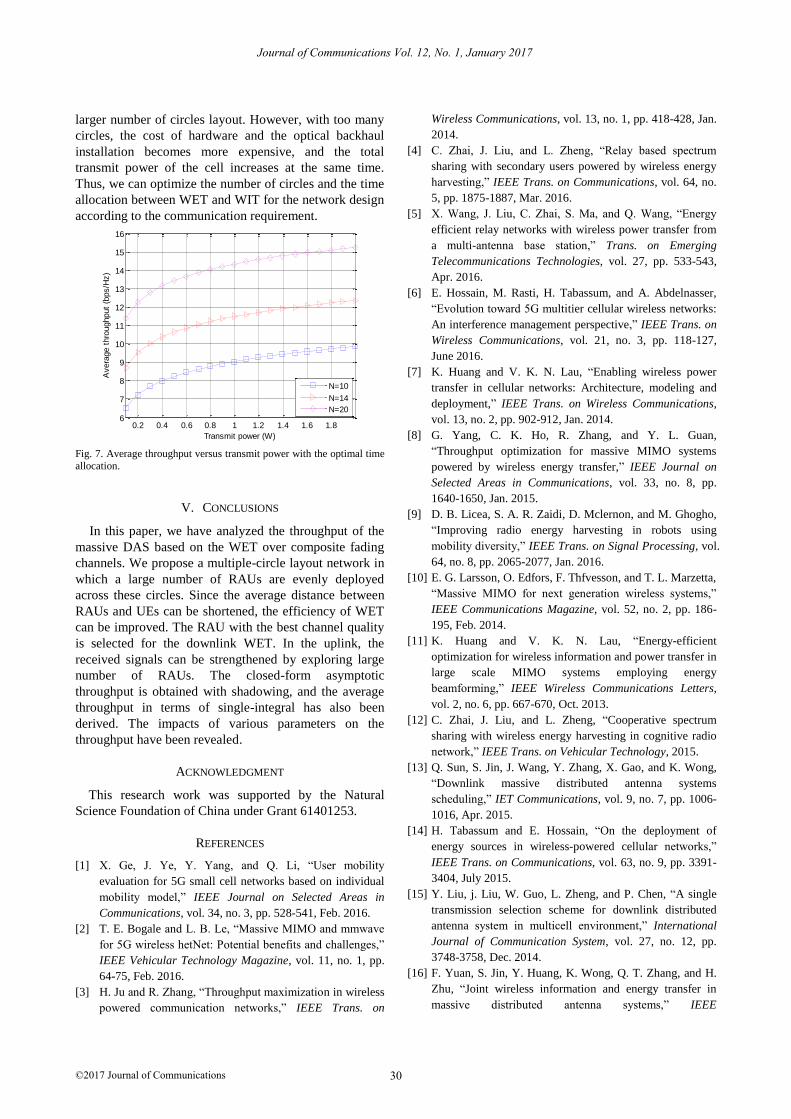
larger number of circles layout. However, with too many
circles, the cost of hardware and the optical backhaul
installation becomes more expensive, and the total
transmit power of the cell increases at the same time.
Thus, we can optimize the number of circles and the time
allocation between WET and WIT for the network design
according to the communication requirement.
0.2 0.4 0.6 0.8 1 1.2 1.4 1.6 1.86
7
8
9
10
11
12
13
14
15
16
Transmit power (W)
Avera
ge t
hro
ughput
(bps/H
z)
N=10
N=14
N=20
Fig. 7. Average throughput versus transmit power with the optimal time
allocation.
V. CONCLUSIONS
In this paper, we have analyzed the throughput of the
massive DAS based on the WET over composite fading
channels. We propose a multiple-circle layout network in
which a large number of RAUs are evenly deployed
across these circles. Since the average distance between
RAUs and UEs can be shortened, the efficiency of WET
can be improved. The RAU with the best channel quality
is selected for the downlink WET. In the uplink, the
received signals can be strengthened by exploring large
number of RAUs. The closed-form asymptotic
throughput is obtained with shadowing, and the average
throughput in terms of single-integral has also been
derived. The impacts of various parameters on the
throughput have been revealed.
ACKNOWLEDGMENT
This research work was supported by the Natural
Science Foundation of China under Grant 61401253.
REFERENCES
[1] X. Ge, J. Ye, Y. Yang, and Q. Li, “User mobility
evaluation for 5G small cell networks based on individual
mobility model,” IEEE Journal on Selected Areas in
Communications, vol. 34, no. 3, pp. 528-541, Feb. 2016.
[2] T. E. Bogale and L. B. Le, “Massive MIMO and mmwave
for 5G wireless hetNet: Potential benefits and challenges,”
IEEE Vehicular Technology Magazine, vol. 11, no. 1, pp.
64-75, Feb. 2016.
[3] H. Ju and R. Zhang, “Throughput maximization in wireless
powered communication networks,” IEEE Trans. on
Wireless Communications, vol. 13, no. 1, pp. 418-428, Jan.
2014.
[4] C. Zhai, J. Liu, and L. Zheng, “Relay based spectrum
sharing with secondary users powered by wireless energy
harvesting,” IEEE Trans. on Communications, vol. 64, no.
5, pp. 1875-1887, Mar. 2016.
[5] X. Wang, J. Liu, C. Zhai, S. Ma, and Q. Wang, “Energy
efficient relay networks with wireless power transfer from
a multi-antenna base station,” Trans. on Emerging
Telecommunications Technologies, vol. 27, pp. 533-543,
Apr. 2016.
[6] E. Hossain, M. Rasti, H. Tabassum, and A. Abdelnasser,
“Evolution toward 5G multitier cellular wireless networks:
An interference management perspective,” IEEE Trans. on
Wireless Communications, vol. 21, no. 3, pp. 118-127,
June 2016.
[7] K. Huang and V. K. N. Lau, “Enabling wireless power
transfer in cellular networks: Architecture, modeling and
deployment,” IEEE Trans. on Wireless Communications,
vol. 13, no. 2, pp. 902-912, Jan. 2014.
[8] G. Yang, C. K. Ho, R. Zhang, and Y. L. Guan,
“Throughput optimization for massive MIMO systems
powered by wireless energy transfer,” IEEE Journal on
Selected Areas in Communications, vol. 33, no. 8, pp.
1640-1650, Jan. 2015.
[9] D. B. Licea, S. A. R. Zaidi, D. Mclernon, and M. Ghogho,
“Improving radio energy harvesting in robots using
mobility diversity,” IEEE Trans. on Signal Processing, vol.
64, no. 8, pp. 2065-2077, Jan. 2016.
[10] E. G. Larsson, O. Edfors, F. Thfvesson, and T. L. Marzetta,
“Massive MIMO for next generation wireless systems,”
IEEE Communications Magazine, vol. 52, no. 2, pp. 186-
195, Feb. 2014.
[11] K. Huang and V. K. N. Lau, “Energy-efficient
optimization for wireless information and power transfer in
large scale MIMO systems employing energy
beamforming,” IEEE Wireless Communications Letters,
vol. 2, no. 6, pp. 667-670, Oct. 2013.
[12] C. Zhai, J. Liu, and L. Zheng, “Cooperative spectrum
sharing with wireless energy harvesting in cognitive radio
network,” IEEE Trans. on Vehicular Technology, 2015.
[13] Q. Sun, S. Jin, J. Wang, Y. Zhang, X. Gao, and K. Wong,
“Downlink massive distributed antenna systems
scheduling,” IET Communications, vol. 9, no. 7, pp. 1006-
1016, Apr. 2015.
[14] H. Tabassum and E. Hossain, “On the deployment of
energy sources in wireless-powered cellular networks,”
IEEE Trans. on Communications, vol. 63, no. 9, pp. 3391-
3404, July 2015.
[15] Y. Liu, j. Liu, W. Guo, L. Zheng, and P. Chen, “A single
transmission selection scheme for downlink distributed
antenna system in multicell environment,” International
Journal of Communication System, vol. 27, no. 12, pp.
3748-3758, Dec. 2014.
[16] F. Yuan, S. Jin, Y. Huang, K. Wong, Q. T. Zhang, and H.
Zhu, “Joint wireless information and energy transfer in
massive distributed antenna systems,” IEEE
Journal of Communications Vol. 12, No. 1, January 2017
©2017 Journal of Communications 30
Communications Magazine, vol. 53, no. 6, pp. 109-116,
June 2015.
[17] A. Yang, Y. Jing, C. Xing, and Z. Fei, “Performance
analysis and location optimization for massive MIMO
systems with circularly distributed antennas,” IEEE Trans.
on Wireless Communications, vol. 14, no. 10, pp. 5659-
5671, June 2015.
[18] W. Feng, Y. Chen, R. Shi, N. Ge, and J. Lu, “Exploiting
macro-diversity in massively distributed antenna systems:
A controllable coordination perspective,” IEEE
Transactions on Vehicular Technology, 2015.
[19] J. Li, D. Wang, P. Zhu, and X. You, “Spectral efficiency
analysis of single-cell multi-user large-scale distributed
antenna system,” IET Communications, vol. 12, no. 8, pp.
2213-2221, Aug. 2014.
[20] J. Li, D. Wang, P. Zhu, and X. You, “Spectral efficiency
analysis of large-scale distributed antenna system in a
composite correlated Rayleigh fading channel,” IET
Communications, vol. 9, no. 5, pp. 681-688, Mar. 2015.
[21] W. Choi and I. G. Andrews, “Downlink performance and
capacity of distributed antenna systems in a multicell
environment,” IEEE Trans. on Wireless Communications,
vol. 6, no. 1, pp. 69-73, Jan. 2007.
[22] J. Li, J. Yan, L. Zhao, and Q. Dong, “Antenna selection
and transmit beamforming optimisation with partial
channel state information in distributed antenna systems,”
IET Communications, vol. 8, no. 13, pp. 2272-2280, Sep.
2014.
[23] H. Li, G. Koudouridis, and J. Zhang, “Antenna selection
schemes for energy efficiency in distributed antenna
systems,” in Proc. IEEE International Conference on
Communications, Ottawa, 2012, pp. 5619- 5623.
[24] Q. Wang, J. Liu, C. Zhai, Y. Liu, X. Wang, and S. Ma,
“Precise error-rate performance with distributed antenna
selection transmission over Nakagami-m fading channels,”
IET Communications, vol. 10, no. 5, pp. 548-557, Mar.
2016.
[25] H. Chen, J. Liu, L. Zheng, C. Zhai, and Y. Zhou,
“Approximate SEP analysis for DF cooperative networks
with opportunistic relaying,” IEEE Signal Processing
Letters, vol. 17, pp. 777-780, June 2010.
[26] S. Wagner, R. Couillet, M. Debbah, and D. T. M. Slock,
“Large system analysis of linear precoding in correlated
MISO broadcast channels under limited feedback,” IEEE
Trans. on Information Theory, vol. 58, no. 7, pp. 4509-
4537, Mar. 2012.
[27] M. Abramowitz and I. A. Stegun, Handbook of
Mathematical Functions with Formulas, Graphs, and
Mathematical Tables, 10th ed. New York: Dover
Publications, 1972.
[28] H. Chen, J. Wang, and M. Chen, “Outage performance of
distributed antenna systems over shadowed Nakagami-m
fading channels,” European Trans. on Tele
Communications, vol. 20, no. 5, pp. 531-535, Nov. 2009.
[29] I. S. Gradshteyn and I. M. Ryzhik, Table of Integrals,
Seires and Products, 7th ed., New York: Academic Press,
2003.
[30] W. Choi and J. Y. Kim, “Forward-link capacity of a
DS/CDMA system with mixed multivariate sources,” IEEE
Trans. on Vehicular Technology, vol. 50, no. 3, pp. 737-
749, May 2001.
Qing Wang received the M.S. and Ph.D.
degrees in Electronic Engineering and
Communication and Information Systems
from the University of Electronic Science
and Technology of China (UESTC) and
Shandong University in 2011 and 2016,
respectively. From September 2013 to
September 2014, he was a visiting
researcher at the University of British Columbia (UBC), Canada.
Since 2016, he
has been with the State Grid Shandong Electric Power Research
Institute. His research interests include massive MIMO and
power line communication.
Hai-Liang Xiong received the B.Sc. and
Ph.D. degrees in communication and
information systems from Xidian
University, Xi'an, China, in 2005 and
2011, respectively. From 2009 to 2011,
he was a visiting scholar at University of
Sheffield (UK) and University of
Bedfordshire (UK). Currently, he is a
lecturer at the school of Information Science and Engineering,
Shangdong University. His research interests include digital
communication and navigation and positioning.
Shan-Shan Yu received his B.S. and
M.S. degree from Ocean University of
China in 2002 and 2006, respectively. He
has been a lecturer of Qufu Normal
University from 2006 to 2014. He is
currently pursuing the Ph.D. degree with
the School of Information Science and
Engineering at Shandong University. His
research interests include device-to-device communications and
massive MIMO.
Yu-Xi Liu received his MS degree in
signal processing from Nanjing
University of Science and Technology
(NJUST), Nanjing, China, in 2008. He
received his Ph.D. degree in
Communication and Information System
from Shandong University (SDU), Jinan,
China, in 2012. Since July 2012, he has
been with the State Grid Electric Power Research Institute and
State Grid Information and Telecommunication Group Co., Ltd.
His research interests include distributed antenna system,
cooperative communications and power line communication.
Journal of Communications Vol. 12, No. 1, January 2017
©2017 Journal of Communications 31