through hole pcb design considerations
TRANSCRIPT

www.smthelp.com
Equipment Throughput Calculation
• Simplistic Throughput Calculation – Deduct a basic rule of thumb percentage from the
maximum machine cycle rate. – The accuracy of this method is highly questionable.
• Effective Throughput Calculation – Machine de-rate calculated using statistical data based
on actual run data and component counts. – Also considers PPM, Product Changeover, Board
Load/Unload Time, and Downtime.

www.smthelp.com
First Pass Yield
Total Components Run - Defects
Total Components Run X 100

www.smthelp.com
Intrinsic Availability
Productive Time
Productive Time + Repair Time X 100
Intrinsic Availability is the percentage the machine operates based on down time attributed to relevant interrupts and active repair or recovery time only.

www.smthelp.com
Total Components Run - Insert Errors
Total Components Run X 100
Insertion/Placement Reliability

www.smthelp.com
• Placement Repeatability for through-hole is not measurable.
Placement Error/Repeatability
• Placement error is based purely on attribute data.
• No meaningful variables data has ever been defined for through-hole processes.

www.smthelp.com
Sum
Cost Per Insertion• CPI Calculation
Equipment Depreciation Expense Replacement Parts Cost Operator Labor Cost Maintenance Labor Cost Divided By Number of Components to Be Inserted
www.smthelp.com
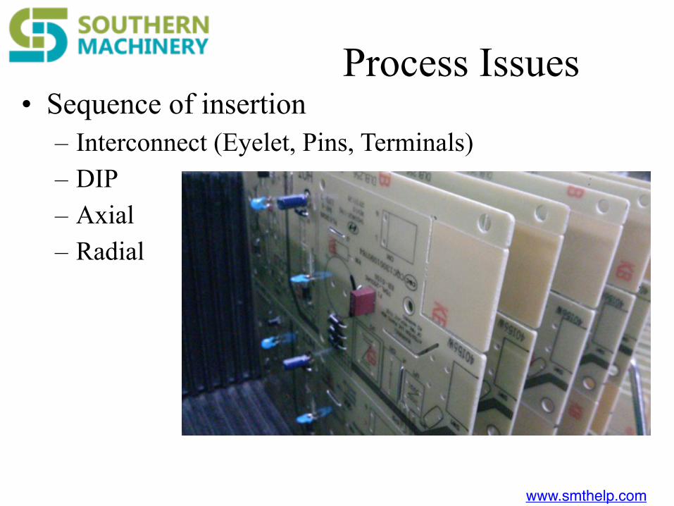
Process Issues• Sequence of insertion
– Interconnect (Eyelet, Pins, Terminals) – DIP – Axial – Radial
www.smthelp.com
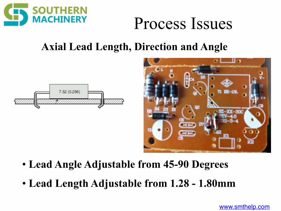
Axial Lead Length, Direction and Angle
• Lead Angle Adjustable from 45-90 Degrees
• Lead Length Adjustable from 1.28 - 1.80mm
Process Issues

www.smthelp.com
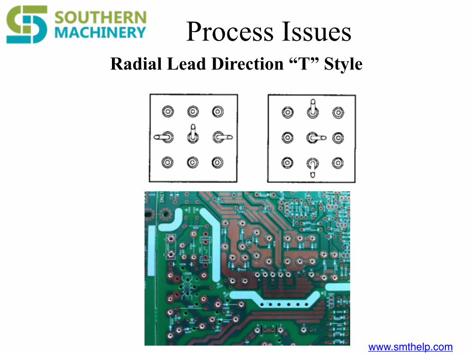
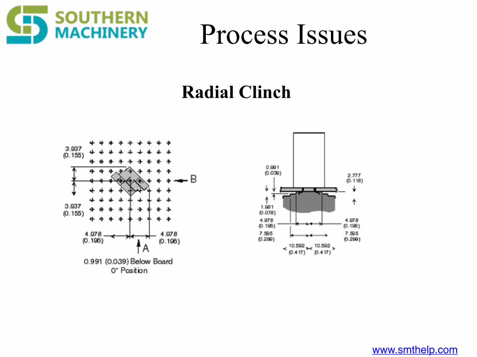
Radial Lead Length and Angle
Lead Length and Angle Hard Tooled (Refer to GS for Selections and Spec.)
Process Issues

www.smthelp.com
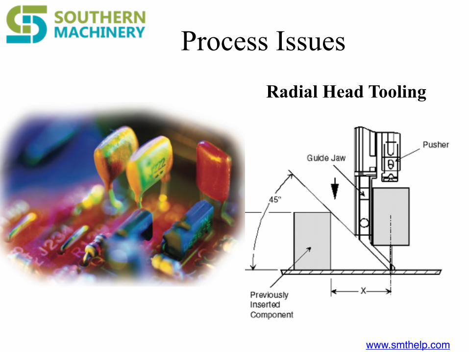
Process Issues• Variables to Lead Length and Angle
– Lead Material – Lead Diameter – Hole Diameter – Lead Hardness


www.smthelp.com
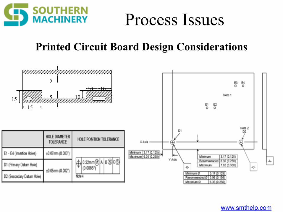
1515
1010 10
5
5
Printed Circuit Board Design Considerations
Process Issues