three-dimensional visualized space - kovi
TRANSCRIPT
International Journal of Architectural Computing 1 –14© The Author(s) 2016Reprints and permissions: sagepub.co.uk/journalsPermissions.navDOI: 10.1177/1478077116663345jac.sagepub.com
Introduction
Large-scale airports such as Incheon International Airport (IIA) have many assets such as lands, buildings, and open spaces. IIA has assets of 2868 lots comprising 49,739,000 m2 of land, 185 buildings with 1,291,000 m2 total floor area, and 9870 open spaces. However, these large-scale assets were managed using dispersed information such as two-dimensional (2D) computer-aided design (CAD) files, drawings printed on papers, various electronic and paper documents, and text-based Enterprise Resource Planning (ERP).
Large-scale asset management using these dispersed pieces of information was very inefficient exempli-fied by dissonance between asset-related 2D CAD drawings and their associated ERP information. The major reason for this dissonance is that expert knowledge was required to process the CAD drawings, and cooperation with other architecture-related departments, which is necessary, was not smooth because the personnel in charge of asset management did not have the required expertise.
Three-dimensional visualized space and asset management system for large-scale airports: The case of Incheon International Airport
Eonyong Kim1 and Soohoon Park2
AbstractLarge-scale airports such as Incheon International Airport have large-scale terminals, annex buildings, and numerous open spaces. An integrated space management system is required to manage these buildings and spaces efficiently. Thus, Incheon International Airport Corporation developed a three-dimensional computer-aided design–based integrated space management system. The major system development goal was to provide intuitive three-dimensional-based visual information, thereby realizing an integrated space and asset management system that does not require expert knowledge of any specific field, such as architecture. This article discusses the construction of the system and the problems that had to be resolved to achieve this goal.
KeywordsSpace and asset management, airport, three-dimensional computer-aided design, building information modeling
1Korea Virtual Reality Inc., Seoul, Korea2Hanbat National University, Daejeon, Korea
Corresponding author:Eonyong Kim, Korea Virtual Reality Inc., 97, Jungdae-ro, Songpa-gu, Seoul, 05719, Korea. Email: [email protected]
663345 JAC0010.1177/1478077116663345International Journal of Architectural ComputingKim and Parkresearch-article2016
Article

2 International Journal of Architectural Computing
To rectify this situation, Incheon International Airport Corporation (IIAC) developed Airport Map (AMAP) for land management and a lease management system called Two Dimension (TWOD), which links 2D CAD and ERP. However, CAD-related expert knowledge was still required, and so it was subse-quently abandoned owing to the complexity of its user interface. Consequently, development was carried out on a new land, building, and space management system that was intuitive and easy for non-experts to use.
Recognizing the problems of conventional management methods and the management systems devel-oped, the first basic system development objective was implementation of a three-dimensional (3D) object-based simplified intuitive user interface that facilitated intuitive integration of dispersed information and increased space and asset management efficiency. This is a strategy for increasing work efficiency by pro-viding an environment in which the system can be actively used when the asset management personnel that is, actual users, carry out the work while reducing resistance against the use of the system.
Two methods were utilized to actualize this strategy. First, a real-time rendering 3D game engine was used, instead of a conventional architectural 3D viewer, to provide increased engagement with the system. To achieve this, a method for processing large-scale 3D files had to be devised. Thus, a new file format was derived for 3D data and downsized for the space management system. The new file format focused on space and asset manage-ment and eliminated unnecessary information, thereby facilitating downsized files. Consequently, operations on the Internet and low-end computers became possible owing to respective improvements in the loading speed and response time of 3D objects and the 3D viewer. Second, to facilitate agreement between drawings and ERP information, a customized 3D CAD system that asset management personnel could use to immediately and easily revise the spaces on drawings and attribute information was adopted. Furthermore, the customized 3D CAD system had the effect of increasing asset information reliability because the shape and information of any areas that were revised were automatically reflected in the 3D viewer in real time.
However, because the focus of the system is on asset and space management, it has a certain limitation; it may be viewed as being insufficient as the building facilities are not reflected from the aspects of facility management (FM) and building information modeling (BIM). These were actually deliberately excluded in order to reduce the probability of failure because the facilities of IIA are too extensive to construct an entire FM system all at once in 3D. Hence, IIAC adopted a modular approach, with the first module of the system developed focusing on space and asset management. Furthermore, to actively reflect the require-ments of the end-users of the system, the real-estate management team oversaw the development of the system. Because the system was developed to increase the efficiency of end-users and with convenience in mind, it is a bit different from the conventional computer-aided facility management (CAFM) perspec-tive. Thus, the development of a geographic information system (GIS)-based 2D Underground FM System was separately carried out. With this approach, risks that can occur during system development were reduced and relevant technologies were accumulated. The BIM model is being considered for application to expand the system, once the current third stage of expansion, including construction of the second ter-minal that utilizes BIM, is completed.
Facility and space management system
Space management is a component of FM. According to the International Facility Management Association (IFMA), FM is defined as a professional field that plans and manages physical work spaces associated with the personnel and works of an organization. In addition, it can be seen as the use of an established plan for management of various equipment and facilities associated with physical work spaces.1 From the definition of IFMA, it is clear that the aim of FM is to increase work efficiency by efficiently managing spaces and their associated elements. In the late 1980s, FM incorporated PC technology and evolved to become CAFM.2CAFM consists of space management and support modules and has further evolved into the Integrated Workplace Management System (IWMS) by integrating new functions for FM and real-estate management; however,

Kim and Park 3
space management is still treated as a core component. Furthermore, owing to adoption of the BIM concept, methods are provided to dynamically and three-dimensionally manage spaces that were previously two-dimensionally managed with 2D CAD and spreadsheet.3
Various solutions4–8 currently provide services in which the FM method is coordinated with BIM. These solutions use a method in which BIM data are incorporated into FM by providing interoperation functions with BIM authoring tools such as Autodesk Revit and Graphisoft ArchiCAD, and, as a major linking method, a method of using Industry Foundation Classes (IFC) files is used. These solutions target not only space management but also all information related to buildings, including the mechanical, electrical, and plumbing (MEP) of buildings, but information related to land is not provided.
Furthermore, to the best of our knowledge, the solutions outlined above have never been applied to the management of large-scale facilities such as an airport. Actual site visits and analysis of LA World Airport (LAX) and Denver International Airport (DIA), which are examples of newly constructed and completed airport facilities utilizing BIM, confirmed that no indoor space management system was constructed at either LAX or DIA, only construction using BIM data and GIS of the functional facilities of the airports such as runways and moorings. We confirmed that the functioning of the systems used in the two airports, which were developed at AECOM on the basis of ESRI ArcGIS and IBM Maximo, was similar to that of the Underground FM System of IIA. Figure 1 shows the system displays of the two airports and relevant systems of IIA such as 2D-based space and land management system, integrated space management system (ISMS) and Underground FM system.
IIAC ISMS
IIAC’s ISMS has been developed between December 2013 and September 2014 (a total development period of 10 months) by the Real Estate Management Team, an asset management department, after commencing
Figure 1. The respective airport FM systems for DIA, LAX, and IIA.

4 International Journal of Architectural Computing
planning at the end of 2012, in order to resolve the inefficiency in space management. One of the major characteristics of this project lies in the proactive enforcement. More specifically, the actual users of this system identified current status and specified requirements for the problem solving of individual cases, unlike conventional and existing planning and ordering systems. For this reason, this system is more in har-monious with the site operations and work processes. Table 1 summarizes the current status and require-ments for the development of ISMS.
One of the challenges from the start of this development project was the short schedule to complete the whole system in just 10 months let alone the tight period of initial 3D modeling in 4 months satisfying the pro-ject design requirements. There were no 3D modeling initial data, and we had a serious decision to make that affects the whole project. The vital decision in the first place was to decide what kind of 3D modeling tools to adopt for our project considering our short period of development schedule. The point was to decide either from the point of building experts view of BIM software or from the viewpoint of ordinary people adopting genuine 3D modeling and visualization tools. Considering the timing and the process of 3D model editing and review-ing, we concluded that the existing BIM software was not appropriate for some reasons. ISMS was not a system for the building experts so that BIM knowledge requirements for the reviewing the 3D model was viewed as a bit excessive. We concluded to modify and adopt the development company possessed 3D object-oriented interior design software which is simple to use and prone to modify to our purpose.
It follows the simplification of modeling entities including wall thickness, height, door types, and so on in order to complete the 3D model in due time. ISMS focuses on asset management rather than building construction so that this simplification issue does not cause problems at all. Net areas of the IIA facilities are calculated based on the center lines and not on the clear distance so that the editing of wall thickness and its simplification do not affect the area calculation of the facilities, and rather it facilitates the working speed through the simplification of building entities so that it greatly reduces time and efforts in 3D modeling of
Table 1. Current status of space management works at IIAC and required improvements for the construction of ISMS.
Work classification Current status Improvements through our system
Area size management
Manages the leased area sizes only Establish a classification system by space and manage areas for every space
Difficult to calculate the area of commonly used space
Establish a calculation logic for the area of commonly used spaces and adopt an automatic calculation function to find the size of commonly used spaces
Drawing management
Dependent on paper drawings Minimize the use of paper drawings even outside of offices with the e-Drawing function on tablet PCs
Renews CAD drawings once a year Update the CAD drawings with 3D drawings in real-time Requires expert knowledge to
analyze drawingsIdentify spatial structures visually and intuitively through use of 3D viewer
Lease management Requires physical visits to a space when renting
Possible to check spaces in the 3D space management system (location, area size, vacancy, etc.)
Manages only charged leases Possible to rationally allocate the limited resources by managing all spaces leased free of charge and at charge
System management
Manages only charged leases Possible to rationally allocate the limited resources by managing all spaces leased free of charge and at charge
Separately manages lands and buildings
Increase the work efficiency by managing lands/buildings in a consistent user environment
IIAC: Incheon International Airport Corporation; ISMS: integrated space management system; CAD: computer-aided design; e-Drawing: electronic drawing; PC: personal computer.

Kim and Park 5
the whole building complex of IIA. There are more critical issues in initial decisions that are further explained in the “System construction strategy” section.
System construction strategy
The basic requirements for construction of ISMS include the following issues, such as every building and space must be implemented in 3D, and the general worry of the Information Technology (IT) team was the effective and easy-to-use visual output of the lands, buildings, floors, and spaces information. This project is mainly for the Asset Management personnel, so we developed some criteria regarding the visualization of this information. We concluded that the normal users need to be guided so that people maintain the initial spatial cognition continuity from the overview of the whole IIA to the specific level of each facilities through the single and fluent process just as a gamer maintains his or her cognitive integrity throughout many stages of a game. Furthermore, the loading time of the 3D model must be less than or equal to 15 s, and the response time for responding to the user’s command was provided as an important criterion. The requirements are summarized as follows:
•• 3D data processing. 3D data must be downloaded from a server, and the response time for showing it on the screen must not exceed 15 s after being requested. However, this criterion is not applied during the editing of a 3D model.
•• Performance of 3D viewer. The 3D viewer must implement a response time without providing incon-venience when a user uses the system. At least 10 fps must be guaranteed.
•• Editing of space. Communication must be facilitated with the system for the CAD system used in editing of spaces. In addition, the changed contents must be automatically processed and reflected in the system without a separate manual operation.
3D model data format. A large-scale facility such as IIA requires large size of 3D data spaces. To resolve this problem, it was first considered to optimize the 3D model file format. Conventional 3D file formats contain much unnecessary space management aspect data, and there are cases in which detailed format information is used. Thus, a new file format was devised to fabricate as a new in-house file format, and the complete understanding of the file format became a basis for satisfying the aforementioned criteria. This was achieved through a trial-and-error process because the criteria could not be satisfied initially owing to use of XML-type format for development convenience, and the processing speed requirement was met by changing it to a binary-type format.
Here comes our next design solution for this project. A singular use of 3D optimized file format does not facilitate all the requirements of 3D processing and visualization of a large-scale building. We suggest the adoption of level of detail (LOD) in order to separate a 3D model according to its visualization purposes. Studies on adopting LOD and space data model started to appear in the late 1990s with the increase in needs and attention on the 3D GIS. In 1998, LOD structure and abstract states were suggested on 3D city model implements in the urban design point of view,9 and it follows that more specific LOD definitions are sug-gested for the City Geography Markup Language (CityGML) as an open data format in large-scale urban 3D modeling works.10 In Korea, national scale LOD definitions are suggested based on CityGML with much more details.11 With the advent of BIM, American Institute of Architects (AIA) suggests another definition of LOD which differs from CityGML.12
We initially considered these existing LOD definitions, and we had many discussions on these implemen-tation issues with many groups in IIAC and finally concluded with our genuine LOD definitions that fit on asset and space management practices. LOD level 1 considers the overview of the whole building envelops and the landscapes. LOD level 2 considers the separation issues of the whole building into separate floor

6 International Journal of Architectural Computing
outlines and conceptual masses which facilitate the fluent spatial cognitive continuity of the IIA space navi-gation. LOD level 3 includes detailed facility spatial data that satisfy space search and facility 3D visualiza-tion (Figure 2).
3D viewer: chaos-free cognition of virtual space access and navigation. In addition to the need to downsize the 3D data, the 3D viewer also had to be revised. Conventional architectural 3D viewers are not appropriate for the ordinary people in terms of speed and degree of visualized expression. Furthermore, there are customiza-tion limitations associated with integrated systems such as ISMS. As a result, we developed a 3D viewer using the Unity 3D game engine, which can perform development flexibly and implement satisfactory visu-alization. The newly designed 3D file format also facilitated the development of the 3D viewer as it was easy to create an importer for file conversion for the 3D viewer.
Viewing issues could be treated differently from the designing and construction point of view of the IIA project. Adopting game engine in the viewing to the ordinary people has many advantages over the existing 3D CAD viewing tools so that it can be more expressive, for example, using motion animation in spreading a building into many separate floor models from LOD level 1 model to LOD level 2 model. Here comes the virtual space access and navigation issue. We spent 5 months to outline our method through various experi-ments and reviews of actual end-users in practice. And we also evaluate this chaos-free virtual space access and navigation solution as one of our main strengths and success points of this project.
There have been many approaches to this virtual space access and navigation problems. Our suggestion is considered to be advanced to other methods in terms of simplicity, sequential cognition, and effective LOD application in viewing. It is simple enough that people’s viewpoint is singularly maintained from the building outline—approach to the access of a room interior. It is sequential so that continuous, temporal, and spatial decisions are made from the overview of the 3D building to the detailed 3D views of various facility interior. Adopting three-level LOD in modeling helps to speed up the virtual space access and navigation, and the selection of a building leads to the spread of floor models, which leads to more specific and detailed 3D floor model, resulting in very positive evaluations during our domestic and international demonstrations with big attention and wow responses.
LOD level 3 floor model includes annexed objects and various signages to improve visual and spatial awareness so that it enables us to search spaces and to identify detailed rented facility and vacancy informa-tion. We also use 3D points of interest (POIs) with space number and name information to identify spaces. Apart from 2D POI, these 3D POIs which change continuously according to the user’s viewpoint are con-strained in numbers and activated under 20 m radius for each selected space in ISMS.
Figure 2. Applied LOD (level of detail) for the building.

Kim and Park 7
We provide a walk-through view in 3D models using identical LOD level models. A camera is selected, and rendering effects such as reflection and transparency are applied. Way-finding problem is also consid-ered using mini-navigation map (key plan to the architects) to identify space information from the display. Figure 3 shows the natural way of approaching from outdoor space to the interior space with simplicity and cognitive sequence. It also illustrates the spread to various consisting floor models, floor space 3D models, and magnification of a specific area.
System design. One of the requirements mentioned before for the system includes 3D model editing capabil-ity by users and registration of the revision on the server. A 3D game engine is not suitable for the 3D model editing capability, and there was a demand for separate 3D CAD software. Existing commercial 3D CAD software were general-purpose tools, and they were too big in size, too time-consuming in installation, and having too many unnecessary functionalities. It turned out to be rational to develop and modify into a speci-fied 3D CAD program that is light enough and specific enough to be appropriate to the space management tasks. This specific 3D CAD tool is not Web-based and client–server type software. Figure 4 illustrates main functions and server interlocking of ISMS.
Figure 4 illustrates the mechanism that the controller in the middle controls the communication between the server and the modules which includes a 3D CAD, Web management screen, and 3D viewer. The server consists of file server and database (DB) server, and the DB server renews the DB through Enterprise Application Integration (EAI) DB adapter before ERP. The Web part category of the server physically resides in the WebSphere Application Server (WAS) and the Web server. A 3D model revision is done by the request through the Web management screen. A Web screen requires drawings that need to be revised to the control-ler; the controller first calls up the Editing module and then transfers the 3D floor model that is required from the file server to the Editing module. The revised space 3D model is transferred to the file server, and at the same time, the viewer 3D model is generated and stored in the file server. The history management function is also provided.
Figure 3. A method of access to indoor space.

8 International Journal of Architectural Computing
User interface. User interface is also considered to be a crucial element in achieving a user-friendly system. Many relevant management systems including various IIAC systems show complex user interfaces with too many buttons that cause delay in learning and mastering the system that naturally causes offensive responses from the user. Our user interface, therefore, shows our design philosophy of “the simpler the better” approach. Figure 5 verifies these ideas. The number of buttons is minimized.
ISMS is built upon this user interface approach, and Figure 6 shows actual key stages of the ISMS. In examples of Figure 6, No. 1 is the initial screen. Nos 2 and 3 show attribute information resulting from the searching of a building. Nos 4–7 show the accessing of an indoor building space, searching space, and checking for space information. Nos 8–10 show the walk-through screens, which facilitate the recognition of spaces from a walking person’s perspective. Nos 11 and 12 show land management operations; nos 13–15 show the Web-based management function; and no. 16 shows the dedicated 3D CAD system display of ISMS for compositing and editing 3D models.
Configuration of ISMS
ISMS consists of three main modules—a main, 3D viewer, and a Web-based management module that pro-vides information for specific space management works—and a field survey system that uses a mobile sys-tem. Figure 7 shows the architecture of the system.
The 3D viewer consists of modules for building and land management and intuitively provides functions for building search, building information, indoor space search, and space information via a unified interface. The screen of the Web-based management system consists of land, building, space, and lease management and provides a function for changing various information and drawings for works associated with ERP in terms of management. For security reasons, the field survey system is designed to download and upload data only through a wired communication network, and the servers cannot be connected to wirelessly.
For ISMS, because all facilities and assets possessed and managed by IIAC are built with 3D models, it is possible to provide a method for expanding and applying it in various fields in the future. This expandability means that ISMS is an open platform for IIA’s 3D model-based management. Based on this platform, a plan is being established to expand it in the future to become an information system for airport security such as closed-circuit television (CCTV) administration, indoor navigation that applies
Figure 4. System modules and operation process.

Kim and Park 9
indoor location tracing technology, real-time tracking of assets such as carts that are difficult to manage, and customer services.
ISMS DB
The DBs of ISMS are linked to ERP and consists of three DBs, respectively, for land information, building information, and space information for self-information processing. However, the field survey system uses the local server to download only those necessary parts of the DB because of the security regulations of IIAC including the banning of Wi-Fi usage in IIA. The construction process for each DB is outlined below, and Figure 8 is a schematization of the construction process of the three DBs:
•• Land information DB. This DB was constructed using GIS information associated with the area where IIA is located.
•• Building information DB. This DB was constructed after identifying the locations of 180 buildings through existing information and field investigations.
Figure 5. User interface.

10 International Journal of Architectural Computing
Figure 6. Examples of the system screen based on the user interface design.
Figure 7. IIAC system architecture.

Kim and Park 11
•• Space information DB. This DB was constructed using the dedicated 3D CAD program specifically produced for ISMS after collecting and organizing the drawing (DWG) files of every building owned by IIAC. Signage and signboards were produced using the photographs taken.
The 3D space model and the property information are separately managed. The 3D CAD file format con-tains an individually unique space code which is used to link with the space master table in the property DB. Figure 9 illustrates the linkage method between the 3D model and the property DB.
User survey
We collected opinions and responses from participating Smart Land expo, user training and hearing to opin-ions before the ISMS opening, and hearing of experts’ opinions through visiting leading international airports in order to enhance the degree of completion of ISMS. There have not been negative responses in terms of general ISMS concepts, approaches, and applied technologies. However, there have been point-outs from the overseas on those facts such as the adoption of a self-file format in 3D data processing and the user-friendly user interface as well as expansion issues after adopting BIM tools. The overseas airport counterparts also cannot show specific solutions to this because they do not have development experiment similar to ISMS using BIM data. The leading overseas airports are now developing and introducing those relevant system cases using BIM data; however, those case experiments only cover exterior models of buildings and GIS-linked management system, with the limitation due to the large-scale 3D model data processing (Figure 10).
There have been many point-outs and opinions mostly from final user training and hearing of opinions that it could be possible to advance from the superficial understanding stage to the specified understanding stage of IIA through ISMS, and expectation seems to be high on huge improvements in work efficiency of IIA space and asset management. Error reports up to now are summarized as follows:
•• Errors on space information. No space information or previous data which are not current are shown.•• Editing software-related errors. Some functions do not work: importing DWG and editing-related
requests, additional function requests, and scale errors when material changes.
Figure 8. DBs for the system and their construction methods.

12 International Journal of Architectural Computing
Most of the errors are caused from the data transferred from ERP, and error corrections are made from the ERP management organization. Editing software-related errors has turned out to be not seri-ous, and patches are provided. DWG file–related requests are now under consideration. The system development period of 10 months is prone to many errors, and now the field maintenance is under way. However, serious system errors such as response speed delay and unexpected system stop have not been reported yet.
Figure 9. The method to link the 3D model and DB.

Kim and Park 13
Summary and future work
The meaning of the ISMS development could be summarized as the bridge role between the conceptual understanding stage of BIM and LOD suggested by building design and construction experts and the practice stage of building life-cycle management of space and asset information. Many stakeholders relevant to building life-cycle information show variety of differences in terms of expertise, requirements, and urgency; however, current BIM is focusing and specifying too much on the building and construction industry experts’ work area. Therefore, requests especially from the operation and management personnel’s requirements are considered not be serious, which leads to our judgment on the difficulty of space and FM based upon BIM technology. Therefore, this project focuses on the system construction not from the viewpoint of building experts but from the bottom-up approach from the operation management–related personnel so that our system might be practically meaningful and achievement is successful. In order to embrace requests from various fields and stances, we have built our experiences, such as the fact that the system should be simpler and more intuitive to the users. We expect that the ISMS will perform the role of good exemplar in future-introducing BIM-based FM.
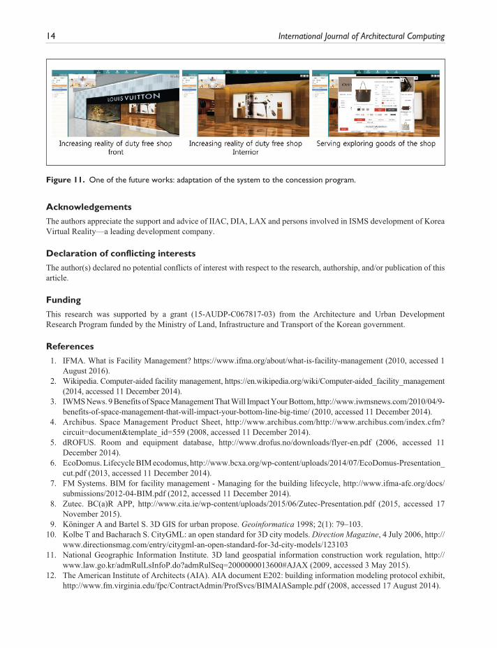
Verification of the high satisfaction on the ISMS in IIAC is revealed from the continuous related orders on additional functionalities of the system. The most significant example is the 3D space information service for the airport and duty-free shop customers. Figure 11 shows the pilot study results on this. The continuous requests occur, including the link with tenant support system and the link with the equipment and FM.
Furthermore, it was successfully commissioned into operation. Accumulation of experiences for process-ing large-scale 3D models through this system was a significant achievement. Using the experience gained from the construction of this system, a method of applying the BIM data to the second passenger terminal, which is currently being constructed using the current BIM, is being devised. At present, a study is being carried out to establish a method of converting an IFC file to an ISMS-applied 3D file format.
Figure 10. User and expert survey of the system.
14 International Journal of Architectural Computing
Acknowledgements
The authors appreciate the support and advice of IIAC, DIA, LAX and persons involved in ISMS development of KoreaVirtual Reality—a leading development company.
Declaration of conflicting interests
The author(s) declared no potential conflicts of interest with respect to the research, authorship, and/or publication of this article.
Funding
This research was supported by a grant (15-AUDP-C067817-03) from the Architecture and Urban Development Research Program funded by the Ministry of Land, Infrastructure and Transport of the Korean government.
References
1. IFMA. What is Facility Management? https://www.ifma.org/about/what-is-facility-management (2010, accessed 1 August 2016).
2. Wikipedia. Computer-aided facility management, https://en.wikipedia.org/wiki/Computer-aided_facility_management (2014, accessed 11 December 2014).
3. IWMS News. 9 Benefits of Space Management That Will Impact Your Bottom, http://www.iwmsnews.com/2010/04/9-benefits-of-space-management-that-will-impact-your-bottom-line-big-time/ (2010, accessed 11 December 2014).
4. Archibus. Space Management Product Sheet, http://www.archibus.com/http://www.archibus.com/index.cfm? circuit=document&template_id=559 (2008, accessed 11 December 2014).
5. dROFUS. Room and equipment database, http://www.drofus.no/downloads/flyer-en.pdf (2006, accessed 11 December 2014).
6. EcoDomus. Lifecycle BIM ecodomus, http://www.bcxa.org/wp-content/uploads/2014/07/EcoDomus-Presentation_cut.pdf (2013, accessed 11 December 2014).
7. FM Systems. BIM for facility management - Managing for the building lifecycle, http://www.ifma-afc.org/docs/submissions/2012-04-BIM.pdf (2012, accessed 11 December 2014).
8. Zutec. BC(a)R APP, http://www.cita.ie/wp-content/uploads/2015/06/Zutec-Presentation.pdf (2015, accessed 17 November 2015).
9. Köninger A and Bartel S. 3D GIS for urban propose. Geoinformatica 1998; 2(1): 79–103. 10. Kolbe T and Bacharach S. CityGML: an open standard for 3D city models. Direction Magazine, 4 July 2006, http://
www.directionsmag.com/entry/citygml-an-open-standard-for-3d-city-models/123103 11. National Geographic Information Institute. 3D land geospatial information construction work regulation, http://
www.law.go.kr/admRulLsInfoP.do?admRulSeq=2000000013600#AJAX (2009, accessed 3 May 2015). 12. The American Institute of Architects (AIA). AIA document E202: building information modeling protocol exhibit,
http://www.fm.virginia.edu/fpc/ContractAdmin/ProfSvcs/BIMAIASample.pdf (2008, accessed 17 August 2014).
Figure 11. One of the future works: adaptation of the system to the concession program.