three-dimensional modeling in medical image processing by using fractal geometry · 2017-03-13 ·...
TRANSCRIPT

Three-Dimensional Modeling in Medical Image Processing by Using Fractal Geometry
Abidin Çalışkan1*, Ulus Çevik2
1 Department of Computer Engineering, Batman University, Batman, Turkey. 2 Department of Electrical and Electronics Engineering, Çukurova University, Adana, Turkey. * Corresponding author. Tel.: 04882173722; email: [email protected] Manuscript submitted December 15, 2015; accepted May 22, 2016. doi: 10.17706/jcp.12.5.479-485
Abstract: Medical images are visualized by computer and processed to obtain larger, more organized, and
three-dimensional (3D) images. Thus, significant images are provided. The processed data facilitate
diagnosis and treatment in the medical fields. The 3D surface models of related areas are formed by using
volumetric data obtained by employing medical imaging methods such as Magnetic Resonance (MR) and
Computer Tomography (CT). The purpose of this study is to obtain 3D images from the two-dimensional CT
slices. These slices are obtained from the existing medical imaging devices and transferred to the z space and
a mesh structure is provided between them. In addition, we investigated 3D imaging techniques,
visualization, basic data types, conversion into main graphical components, and imaging algorithms. At the
phase of obtaining 3D images; the image processing methods such as surface and volume imaging
techniques, smoothing, denoising, and segmentation were used. The complexity and efficiency properties of
the imaging algorithms were investigated and image enhancement algorithms were utilized.
Key words: Medical imaging, visualization, imaging algorithm, 3D.
1. Introduction
Biomedical is a field which has been drawing attention rapidly in recent years, and in which researches
have been gathering momentum. It is also a source of inspiration for many work areas and problems in
terms of the devices used and the processing of the digital images obtained from these devices. Although the
devices are in the forefront in the biomedical field, it is of great significance how the images obtained from
these devices are processed, how they are structured and how they are made consistent with each other.
Nowadays, the 3D models are needed in various fields such as medical, animation, and simulation. Medical
imaging has an effective role in 3D visualization, medical education, and diagnosis of diseases without
requiring any surgical intervention. The surgical simulations particularly in the 3D models have an important
role for the medical developments to gain momentum.
The available 3D objects, whose sizes are not known commonly or whose models are not present, can be
re-modeled. In order to achieve this, it is required to use the reverse engineering technique. The measuring
data used in reverse engineering are obtained by using point clouds or cross-sections, coordinate
measurement or optics, laser scanning devices. Number of studies concerning acquisition of 3D models from
the two-dimensional (2D) images, taken by using digital cameras, has increased in recent years [1].
Nowadays, it is observed that the data obtained from MR and CT devices consist of images taken in
different positions such as head and femur in certain areas [2]. Although these images give precise results,
Journal of Computers
479 Volume 12, Number 5, September 2017

the results required to be achieved in the images on the medical files occasionally cause some problems.
Interferences in data or problems arising from the environment are among various problems. In order to
achieve the desired standards in the images, the roughness can now be removed by using image processing
techniques.
In a period of time when medical images have become so important; despite the fact that the devices give
the very precise data, it is not possible to prevent interferences and spots in some areas in the images to a
certain extent due to factors such as radiation, light coming into environment, and human. The elimination
of these impurities in the images, the requests emerging over time, converting the images from 2nd
dimension to 3rd dimension, specifying the contours, the desire to draw the contours and realizing product
designs from these data have required processing of medical images.
When it is required to obtain 3D medical images, 2D data taken from the medical imaging devices are
transferred to the z space by passing them from various algorithms. It has been aimed to obtain 3D data after
the mesh between the data is provided. The fractal geometry and the box-counting method of the fractal
geometry have been used at the present time in order to transfer especially the complex objects to the 3D.
This method enables to obtain more precise results in transferring the data to the 3D and, also more smooth
results after being modeled.
Medical imaging technology that develops rapidly has transferred the pixel data of the images, obtained in
the data produced, to the 3D (z space) and formed a volumetric voxel. The first head and body voxel models
were formed by using the CT of a female cadaver [2].
Lai et al., (1999) used an algorithm, based on the reverse engineering technique, for 3D surface reverse
construction of CT images [3].
Liu and Ma (1999) utilized a layer-based core growth technique and developed a method providing the 3D
surface segmentation of the contour data obtained from CT. They obtained the layer-based 3D contour model
in 2D CT images after pre-processes [4].
Various softwares using volume or surface rendering techniques have been developed for 3D medical
imaging techniques. The "Marching Cubes" algorithm has been used for the 3D surface models of relevant
areas by using volumetric data obtained through medical imaging techniques such as MR and CT [5]. The
“Marching Cubes” algorithm has been found as the method which achieves the result in the fastest way in
forming 3D data in terms of processing time and structure appropriateness and compared to the other
algorithms [6], [7]. By using iso-surface extraction method, the surface models were obtained from the CT
and MR data and as a result of these applications, statistical data and results were found out [8], [9].
In order to generate a 3D Computer-Assisted Design (CAD) model over the medical images, 3D models
were tried to be formed by the help of contour algorithms [10]. The computer-focused algorithms presented
by Lee and Chung (2005) in order to find the contour specification and thresholding of the femur bone have
shed light on such studies [11].
Fractal geometry produces more applicable solutions in structure modeling of the irregular pieces in the
universe. It is used widely for the modeling of the materials to be produced aesthetically in architectural and
engineering applications [12]–[14].
The box-counting method was used for the analogy and comparison of 2D images as 3D [15].
Fig. 1 illustrates the algorithm, whose contour specification method has been developed with the fractal
bases. As a result, more precise and measurable results were obtained compared to the current histogram
structures and contour specification data [16].
In this study, firstly, some segmentation processes were performed for denoising of the data. In addition to
these segmentation processes, filtering algorithms were tried to obtain the required contour areas.
Additionally, studies were carried out in order to specify the threshold values over the existing data. In the
Journal of Computers
480 Volume 12, Number 5, September 2017

second section, fractal geometry applications were studied. The fractal geometry sets were shown in 3D
with options. In addition, the existing medical imaging data and some relevant values (Hausdorff Dimension)
were presented and transferred to graphics. In the last section, processes of transfer to the 3D were applied.
One of the most significant points in this section was to use the medical images in a data set for such process
of transfer to the 3D. The "marching cubes" algorithm was applied to form the mesh structure in medical
images, whose data set was created.
Fig. 1. Flowchart of the contour specifying algorithm.
The interferences in the images obtained from the X-ray devices were removed by using box-counting
method, which is a fractal method, in the required segmentation processes [17].
2. Material and Method
In this study; Fig. 2 illustrates process steps of reading the medical images, the segmentation processes in
the medical images, the fractal geometry processes as the method required to be applied, and the application
processes over the medical image, passing of the present 2D medical data from the marching cubes
algorithm, and presentation of a 3D visual model.
Fig. 2. Process steps of the method developed.
2.1. CT Cross-Section Image Representation
The units measured in CT are the rectangular prisms that are formed by the pixels as the bottom and the
section thickness as the height. These prisms are called as “voxel” that means the volume element. Every CT
cross-section is divided in matrices in a 512512 voxel size. The density value of the tissue in every point in
the image section is calculated. These density or attenuation values calculated are converted into X-ray
holding values of each voxel via computers. These values are compared to the density value of the water and
shown on a scale called as Hounsfield Unit (HU). According to the Hounsfield scale, a number is given to all
the voxels. This number is a plus value in the tissues with higher density than water and a minus value for
those having lower density than water. Lastly, the voxels that have numerical values according to the
Hounsfield scale are painted with white, black and the gray tones. In Fig. 3, a gray scale with a white plus end
and a black minus end is used [18].
Image
Calculation of the Fractal
Dimension
Normalization of the Fractal Dimension
Specifying the Contour of the
Fractal Dimension
Specifying the Thresholding
Value
Histogram Processes over
the Wavelengths
Reading the Data
Filtering Processes
Fractal Application
Marching Cube
3D Modeling
Journal of Computers
481 Volume 12, Number 5, September 2017
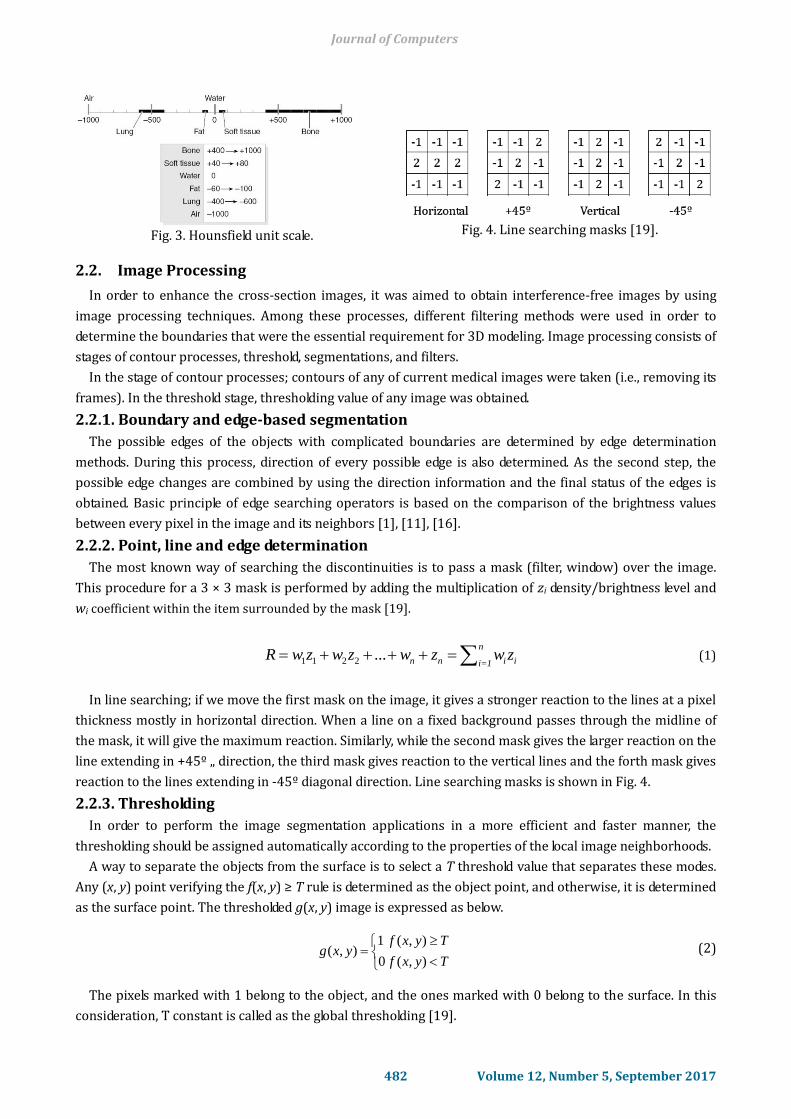
Fig. 3. Hounsfield unit scale.
Fig. 4. Line searching masks [19].
2.2. Image Processing
In order to enhance the cross-section images, it was aimed to obtain interference-free images by using
image processing techniques. Among these processes, different filtering methods were used in order to
determine the boundaries that were the essential requirement for 3D modeling. Image processing consists of
stages of contour processes, threshold, segmentations, and filters.
In the stage of contour processes; contours of any of current medical images were taken (i.e., removing its
frames). In the threshold stage, thresholding value of any image was obtained.
2.2.1. Boundary and edge-based segmentation
The possible edges of the objects with complicated boundaries are determined by edge determination
methods. During this process, direction of every possible edge is also determined. As the second step, the
possible edge changes are combined by using the direction information and the final status of the edges is
obtained. Basic principle of edge searching operators is based on the comparison of the brightness values
between every pixel in the image and its neighbors [1], [11], [16].
2.2.2. Point, line and edge determination
The most known way of searching the discontinuities is to pass a mask (filter, window) over the image.
This procedure for a 3 × 3 mask is performed by adding the multiplication of zi density/brightness level and
wi coefficient within the item surrounded by the mask [19].
1 1 2 2 ...n
n n i ii=1R w z w z w z w z (1)
In line searching; if we move the first mask on the image, it gives a stronger reaction to the lines at a pixel
thickness mostly in horizontal direction. When a line on a fixed background passes through the midline of
the mask, it will give the maximum reaction. Similarly, while the second mask gives the larger reaction on the
line extending in +45º „ direction, the third mask gives reaction to the vertical lines and the forth mask gives
reaction to the lines extending in -45º diagonal direction. Line searching masks is shown in Fig. 4.
2.2.3. Thresholding
In order to perform the image segmentation applications in a more efficient and faster manner, the
thresholding should be assigned automatically according to the properties of the local image neighborhoods.
A way to separate the objects from the surface is to select a T threshold value that separates these modes.
Any (x, y) point verifying the f(x, y) ≥ T rule is determined as the object point, and otherwise, it is determined
as the surface point. The thresholded g(x, y) image is expressed as below.
Tyxf
Tyxfyxg
),(
),(
0
1),( (2)
The pixels marked with 1 belong to the object, and the ones marked with 0 belong to the surface. In this
consideration, T constant is called as the global thresholding [19].
Journal of Computers
482 Volume 12, Number 5, September 2017

2.2.4. Filters
In this part, various boundary determining algorithms were processed and different boundary finding
results were obtained. Sobel filter performs the filtering process related to the neighborhood center. Sobel
filter of any selected cross-section is obtained and shown in Fig. 5. The threshold is automatically calculated
in the Sobel filter.
Fig. 5. Sobel filter application.
Fig. 6. Prewitt filter application.
The Prewitt filter has a simpler structure than the Sobel filter. This filtering method allows addition of
various noises. Fig. 6 illustrates the result obtained with the Prewitt filter application.
2.3. Fractal Geometry
Fractal geometry provides to obtain rich graphical images by courtesy of the mathematical iterations that
can be performed by a computer [12].
Another property of fractals is the property of self-similarity which we commonly encounter in nature. A
fractal figure that is formed by any iteration system occurs by various successive iterations of the same
mathematical formula core [20].
A sample fractal image is shown in Fig. 7.
Fig. 7. A sample for fractal geometry iterations.
2.4. Methods for forming 3D Models from 2D Data
For 3D visualization, one of the volume rendering methods, marching cubes, or dividing cubes techniques
can be selected. Volume rendering takes more time when compared to the others. Dividing cubes is more
suitable for software-based imaging. The technique of marching cubes is generally preferred for a
hardware-based polygon imaging or if a motion process will be performed within the surface removed [5].
2.4.1. Method of marching cubes
Method of Marching Cubes is based on the principle of polygoning of the scalar areas, which are sampled
numerically, between cross-sections with a divide and process type logic from 3D data. It is ensured to divide
such sampled areas into cubes consisting of 8 volumetric points and determine whether these points remain
within iso-surfaces. In basic cells that are considered to have an octagonal cube structure, 256 different
conditions may occur.
Journal of Computers
483 Volume 12, Number 5, September 2017

3. Application and Performances
The purpose of this study was to process 2D medical data and to convert them into 3D. Thus, it was tried
to primarily read the medical images, and then realize the segmentation processes on them, perform the
fractal geometry studies, which was the method required to be applied, on the medical image, and lastly to
present a 3D visual model by passing these current medical data from the marching cube algorithm.
In the processes in fractal stage, some statistical analyses of the present images were performed regarding
the fractal geometry. The box counting method of the fractal geometry was applied on these medical images
and the region and self-similarity methods were used.
This is the section of the medical images that was transferred to the z dimension, i.e. 3D after using
various boundary follow-up and similarity methods. Input cross-sections and output set image is shown in
Fig. 8.
Fig. 8. Input cross-sections and output set.
Fig. 9. Modeling of the 3D image
obtained.
In this stage, marching cubes algorithms were applied for imaging modeling. By this algorithm, meshing
process was performed on the current medical images. Mesh application structure provided the connection
of medical image sections with each other.
Fig. 9 illustrates the surface wrapping processes of the data obtained by the mesh structure.
4. Conclusions
Rapid development of technology and daily developments in medical field open new ways for researchers
continuously. In this study, data having medical file extensions were passed through various image
processing stages, and boundary determination operations were performed. From the cross-sections, whose
boundaries were specified sensitively, the marching cube algorithm was used in the mesh structures
together with the values obtained from the medical images that were then developed as a data set. Some
fractal algorithms (Hausdorff Dimension) were used, and the similarity ratios were found. Owing to the mesh
structures from 2D data to 3D data, and functions given by the platform developed by present application
software, the surface mesh process was also performed.
References
[1] Urban, J. E., & Tester, J. T. (2009). Using two-dimensional edge detection to produce three-dimensional
medical prototypes from MRI data. Proceedings of 25th Southern Biomedical Engineering Conference
(pp. 67-70). Miami, Florida, USA. Springer Berlin Heidelberg.
[2] Gibbs, S. J., Pujol, A., Chen, T. S., Malcolm, A. W., & James, A. E. (1984). Patient risk from interproximal
radiography. Oral Surgery, Oral Medicine, Oral Pathology, 58(3), 347-354.
[3] Lai, J. Y., Doong, J. L., & Yao, C. Y. (1999). Three‐dimensional CAD model reconstruction from image data
of computer tomography. International Journal of Imaging Systems and Technology, 10(4), 328-338.
Journal of Computers
484 Volume 12, Number 5, September 2017
[4] Liu, S., & Ma, W. (1999). Seed-growing segmentation of 3-D surfaces from CT-contour data.
Computer-Aided Design, 31(8), 517-536.
[5] Lorensen, W. E., & Cline, H. E. (1987). Marching cubes: A high resolution 3D surface construction
algorithm. ACM Siggraph Computer Graphics, 21(4), 163-169.
[6] Guha, S. (1994). An optimal mesh computer algorithm for constrained Delaunay triangulation.
Proceedings of Eighth International Parallel Processing Symposium (pp. 102-109).
[7] Chan, S. L., & Purisima, E. O. (1997). A new tethedral tessellation scheme for isosurface generation.
Comput. & Graphics, 22(1), 83-90.
[8] Cignoni, P., Montani, C., Puppo, E., & Scopigno, R. (1996). Optimal isosurface extraction from irregular
volume data. Proceedings of Symposium on Volume Visualization (pp. 31-38).
[9] Lee, C., & Lee, J. (2006). Computational anthropomorphic phantoms for radiation protection dosimetry.
Evolution and Prospects, Nuclear Engineering and Technology, 38(3), 239-250.
[10] Ryu, J. H., Kim, H. S., & Lee, K. H. (2004). Contour-based algorithms for generating 3D CAD models from
medical images. The International Journal of Advanced Manufacturing Technology, 24(1-2), 112-119.
[11] Lee, J. S., & Chung, Y. N. (2005). Integrating edge detection and thresholding approaches to segmenting
femora and patellae from magnetic rezonance images. Biomedical Engineering: Applications, Basis and
Communications, 17(1), 1-11.
[12] Kenkel, N. C., & Walker, D. J. (1996). Fractals in the biological sciences. Coenoses, 11(2), 77-100.
[13] Cross, S. S. (1997). Fractals in pathology. The Journal of Pathology, 182(1), 1-8.
[14] Heymans, O., Fissette, J., Vico, P., Blacher, S., Masset, D., & Brouers, F. (2000). Is fractal geometry useful
in medicine and biomedical sciences? Medical hypotheses, 54(3), 360-366.
[15] Jennane, R., Harba, R., Lemineur, G., Bretteil, S., Estrade, A., & Benhamou, C. L. (2007). Estimation of the
3D self-similarity parameter of trabecular bone from its 2D projection. Medical Image Analysis, 11(1),
91-98.
[16] Zhu, Q., Wang, Y., & Liu, H. (2010). Edges extraction method based on fractal and wavelet. Journal of
Computers, 5(2), 282-289.
[17] Wang, J., Hou, X., & Cai, Y. (2008). Segmentation of casting defects in X-ray images based on fractal
dimension. Proceeding of the 17th World Conference on Nondestructive Testing (pp. 25-28).
[18] Kılıç, N. (2008). Colon Segmentation and the Detection of Colonic Polyp with Template Matching in CT
Images, PhD thesis, Istanbul University, Institute of Naturel and Applied Sciences.
[19] Gonzalez, R. C., Woods, R. E., & Eddins, S. L. (2004). Digital Image Processing Using MATLAB, Pearson
Education India.
[20] Mandelbrot, B. B. (1983). The Fractal Geometry of Nature, 173, Macmillan.
Abidin Çalışkan received his M.Sc. degrees in computer engineering from the University of
Fırat, Turkey, in 2012. Currently, he is a research assistant in Computer Engineering
Department at the University of Batman, Turkey, and working on his doctoral research in
volume graphics.
Ulus Çevik received his PhD in electrical and electronic engineering from the University of
Sussex, UK in 1996. Currently, he is an assistant professor of electrical and electronic
engineering at Çukurova University, Turkey. His research interests include computer graphics
and programmable logic.
Authr’s formal photo
Authr’s formal photo
Journal of Computers
485 Volume 12, Number 5, September 2017