three dimensional cohesive-element analysis and … three... · 2012-12-19 · three dimensional...
TRANSCRIPT

Three dimensional cohesive-element analysis andexperiments of dynamic fracture in C300 steel
A. Pandol®a, P.R. Gudurub, M. Ortizb,*, A.J. Rosakisb
aDipartimento di Ingegneria Strutturale, Politecnico di Milano, 20133, Milano, ItalybGraduate Aeronautical Laboratories, California Institute of Technology, Mail Stop 105-50, Pasadena, CA 91125, USA
Received 9 November 1998; in revised form 6 May 1999
Abstract
The dynamic drop-weight test is taken as a convenient basis for assessing the ®delity and predictive ability ofcohesive models of fracture in applications involving dynamic crack growth. In the experimental phase of the study,coherent gradient sensing (CGS) has been used to study dynamic fracture in C300 maraging steel. The specimens
were subjected to three-point bend impact loading under a drop weight tower. High-speed photographs of the CGSinterferograms were analyzed to determine the crack tip location, the velocity and the dynamic fracture toughness asa function of time. Post-mortem examination of the specimens revealed the fractography of the fracture surfaces,
including the development of shear lips. In a parallel numerical phase of the study, fracture has been modeled byrecourse to an irreversible cohesive law embedded into cohesive elements. These cohesive elements govern all aspectsof the separation and closure of the incipient cracks. The cohesive behavior of the material is assumed to be rate
independent. The ®nite element model is three dimensional and consists of quadratic ten-noded tetrahedra. Thenumerical simulations have proven highly predictive of a number of observed features, including: the crack growthinitiation time; the trajectory of the propagating crack tip; and the formation of shear lips near the lateral surfaces.The simulations therefore establish the feasibility of using cohesive models of fracture and cohesive elements to
predict dynamic crack-growth initiation and propagation in three dimensions. 7 2000 Elsevier Science Ltd. Allrights reserved.
Keywords: Dynamic fracture; Coherent gradient sensing; 3D cohesive elements; C300 steel; Three point bend; Drop weight test
1. Introduction
When a mode I crack initiates dynamically, after the satisfaction of an appropriate dynamic crack
International Journal of Solids and Structures 37 (2000) 3733±3760
0020-7683/00/$ - see front matter 7 2000 Elsevier Science Ltd. All rights reserved.
PII: S0020-7683(99 )00155-9
www.elsevier.com/locate/ijsolstr
* Corresponding author. Fax: +1-626-304-0175.
E-mail address: [email protected] (M. Ortiz).

initiation condition (Owen et al., 1998), it grows with a crack tip speed history not predictable bycontinuum mechanics alone. To describe the crack tip history, we require the notion of a dynamic crackgrowth toughness which would in general be a material-dependent function of a near tip measure of thelocal deformation rate. For growing cracks, the dominant contribution to the strain rate near thepropagating crack tip is proportional to the instantaneous crack tip speed. As a result, the dynamicfracture toughness is expected to be some material-dependent function of the crack tip speed. Theseobservations suggest a dynamic fracture criterion of the form (e.g. Freund, 1990):
K dI �a�t�, t, load � � KD�v� �1�
where a(t ) is the time-dependent crack length and v is the crack velocity a.(t ). The left-hand side of this
equation, namely, the instantaneous stress intensity factor K dI , measures the strength of the near-tip
®elds which drive crack propagation. The right-hand side of the equation, called the dynamic fracturetoughness, KD, represents the resistance of the material to crack propagation, with the attendantdissipative mechanisms, such as surface energy and plasticity, and material inertia subsumed within it.As implied in Eq. (1), KD is generally supposed to be a function of the crack velocity v. Numericalanalyses by Freund and Douglas (1982) and Lam and Freund (1984) have shown that, for elastic±plasticmaterials, material inertia shields the crack tip plasticity for a propagating crack. Correspondingly, formaterials obeying McClintock and Irwin's (1964) fracture criterion, i.e. the attainment of a criticalplastic strain at a ®xed critical distance ahead of the crack tip, the aforementioned numerical analysesreveal that KD(v ) is an increasing function of v, in keeping with experimental observation. Rosakis andZehnder (1985) have shown that this type of analyses are predictive of the variation of KD with v forappropriately assumed values of certain parameters.
Over the past two decades, considerable experimental e�ort Ð using a variety of techniques Ð hasbeen devoted to the development of methods to measure KD(v ), and to ascertaining if it indeed is amaterial property. In addition to direct optical techniques such as the method of caustics, photoelasticityand coherent gradient sensing (CGS), certain hybrid methods have also been used for this purpose.Brickstad (1983) conducted dynamic fracture experiments on a high strength steel where the crackvelocity and boundary displacements were experimentally measured and were used as input to anumerical analysis to infer the variation of KD(v ). A signi®cant result of this work is that KD(v ) doesnot show a discernible dependence on v
., i.e. the crack acceleration, which is consistent with experimental
observations (Dally, 1979). Employing an analogous procedure, Kanazawa et al. (1981) obtained anextensive set of data concerning KD(v ) at various test temperatures for a Si±Mn steel. In addition,taking advantage of the large size of the specimens, they made use of the data to predict v vs a for agiven boundary loading. The results are in good agreement with experiments. In their procedure, theymade use of Freund's (1972) decomposition of K d
I (a, v ) into a product of functions of a and v alone.A similar approach was adopted by Angelino (1978) who inferred KD from boundary load and
displacement measurements. Though prone to errors in crack-velocity estimation, this method yieldedKD values for SAE 4340 steel that are in good agreement with those reported by other investigators. Aslightly di�erent methodology was adopted by Bilek (1980), who subjected double cantilever beam(DCB) specimens made of 4340 steel to wedge loading and measured crack speed and boundarydisplacements. This information was used in the numerical solution of an analytical model in which theDCB specimen was modeled as a Timoshenko beam on a rigid foundation. His results suggest that KD
goes through a minimum before rapidly rising as a function of v. The issue of KD going through aminimum at a nonzero velocity is of great signi®cance in crack arrest considerations. Given theinaccuracies in the measurement of crack velocity and the limitations in the interpretation of theexperimental results, this question invites further experimental studies with improved accuracy. From
A. Pandol® et al. / International Journal of Solids and Structures 37 (2000) 3733±37603734

the theoretical point of view, this phenomenon has been recently linked to material rate sensitivity bythe work of Freund and Hutchinson (1985) and Freund et al. (1986).
Despite these advances, the dynamic fracture criterion (1) should not be construed as a universalrelation, and the assumptions implicit in such criteria, which determine their scope and range ofapplicability, should be carefully noted. Firstly, since (1) is written in terms of stress-intensity factors,the small-scale yielding condition of linear-elastic fracture mechanics (LEFM) is tacitly assumed to be inforce. For this assumption to be appropriate, the plastic zone must be con®ned to a region near the tipof the crack much smaller that any and all remaining geometrical dimensions of the problem, includingthe crack length, ligament size, and others. Secondly, a statement of the form (1) tacitly presumes thatthe asymptotic near-tip ®elds, including plastic deformations and inertia, are autonomous, with theirform independent of the shape and size of the crack, the geometry of the body, the loadingcon®guration and the load history. Under these conditions, the near-tip ®elds which mediate theseparation processes are fully characterized by a limited set of parameters, e.g. the stress-intensityfactors, and it is reasonable to assume that the crack-tip motion is a function of these parameters only.In e�ect, the principal objective behind the dynamic fracture criterion (1) is to conveniently encapsulatea vast array of micromechanical processes attendant to a moving crack tip, such as plasticity, inertia,heat conduction and others, so that such phenomena need not be explicitly accounted for in full-systemanalyses.
In many cases, however, it may be unreasonable to expect that such complex interacting processes asaccompany a running crack may be subsumed within as simple a relation as (1). For instance, thefracture criterion (1) may be expected to break down under fully yielded conditions, or near a freesurface owing to the emergence of shear lips. In the work presented in this paper, we have endeavoredto validate an entirely di�erent approach based on:
1. Multiscale analysis. Advances in adaptive mesh re®nement and other computational methodspresently enable the simultaneous resolution of full-system ®elds as well as near-tip ®elds, with theresult that the latter need not be accounted for, i.e. buried, in the fracture criterion.
2. Cohesive theories of fracture. The explicit resolution of the near-tip ®elds has the far-reachingconsequence that only the actual surface-separation processes need to be contemplated in the fracturecriterion. Here, those separation processes are modeled by recourse to cohesive theories of fractureand their computational embodiment, cohesive elements.
In the present work, we take the dynamic drop-weight test as a convenient basis for assessing thepredictive ability of cohesive models of fracture in applications involving dynamic crack growth. Thesemodels Ð pioneered by Dugdale (1960), Barrenblatt (1962), Rice (1968) and others Ð regard fractureas a gradual phenomenon in which separation takes place across an extended crack `tip', or cohesivezone, and is resisted by cohesive tractions. Cohesive models enable the incorporation into the analysis ofbona ®de fracture parameters such as the spall strength Ð the peak cohesive traction Ð and thefracture energy Ð the area under the cohesive law Ð of the material. In particular, the existence of awell-de®ned fracture energy endows the solid with characteristic, or `intrinsic', spatial and temporallengthscales. The particular class of cohesive law contemplated in the present work is due to Ortiz andPandol® (1999) and accounts for ®nite kinematics and irreversible behavior. Other alternativeformulations may be found elsewhere (Rose et al., 1981; Needleman, 1987; Ortiz, 1988; Beltz and Rice,1991; Rice, 1992; Ortiz and Suresh, 1993).
Cohesive laws have been built into ®nite element analyses as mixed boundary conditions (Hillerborget al., 1976; Carpinteri, 1986; Needleman, 1987, 1990a, b, 1992; Xu and Needleman, 1993; Planas et al.,1994; Tvergaard and Hutchinson, 1993, 1996a, b) or have been embedded into cohesive ®nite elements(Willam, 1989; Ortiz and Suresh, 1993; Camacho and Ortiz, 1997; Xu and Needleman, 1994, 1995, 1996;De-Andre s et al., 1998; Ortiz and Pandol®, 1999). These elements are surface-like and are compatible
A. Pandol® et al. / International Journal of Solids and Structures 37 (2000) 3733±3760 3735

with general bulk ®nite element discretizations of the solid, including those which account for dynamics,plasticity and large deformations. Cohesive elements bridge nascent surfaces and govern their separationin accordance with a cohesive law. In two-dimensional fragmentation simulations, both plane strain andaxisymmetric, Camacho and Ortiz (1996) and Ortiz (1996) have established the feasibility of usingcohesive elements to account explicitly for individual cracks as they nucleate, propagate, branch andpossibly link up to form fragments, as well as of simulating explicitly the granular ¯ow which ensuesfollowing widespread fragmentation. Camacho and Ortiz (1996) have also shown that mesh-sizeindependent results are obtained when the mesh adequately resolves the cohesive zone. The ®delity ofcohesive elements in applications involving dynamic fracture in ductile materials has recently beeninvestigated by Pandol® et al. (1999), who have simulated the expanding 1100-0 aluminum ring test ofGrady and Benson (1983). The numerical simulations have been found to be highly predictive of anumber of observed features, including: the number of dominant and arrested necks; the fragmentationpatterns; the dependence of the number of fragments and the fracture strain on the expansion speed;and the distribution of fragment sizes at ®xed expansion speed.
The organization of the paper is as follows. The test con®guration and diagnostic techniquesemployed in the experimental phase of this study are brie¯y discussed in section 2, which also collectsthe observational data and their analysis. The particulars of the cohesive laws and elements adopted inthe numerical phase of the study are succinctly summarized in section 3. Detailed comparisons betweenfull three-dimensional ®nite-element simulations and the experimental data are presented in section 4.These comparisons demonstrate that cohesive theories accurately predict sensitive aspects of thedynamic fracture of C300 steel such as crack-growth initiation conditions and crack propagationvelocities.
2. Dynamic fracture of C300 steel
A common approach in dynamic fracture testing is to observe the propagating crack tip area using anoptical technique and to infer the K d
I value. These methods rely upon an accurate analytical descriptionof the near crack tip stress ®elds. A number of analytical crack-tip ®elds are presently available givingthe dominant singular term as well as higher-order expansions for many problems, including steady-statecrack propagation and transient crack propagation. Some of the experimental methods presently in useare caustics, photoelasticity and CGS. Early attempts at using the method of caustics for propagatingcracks were made by Kaltho� et al. (1976), Katsamanis et al. (1977), Theocaris (1978) and Goldsmithand Katsamanis (1979). They used quasi-static crack-tip ®elds for analyzing the dynamic shadowpatterns, neglecting inertial e�ects. As the crack velocity becomes a substantial fraction of the Rayleighwave speed, the inertial e�ects signi®cantly modify the crack tip stress ®elds. Kaltho� et al. (1978)introduced an approximate correction factor to be applied to static analysis to account for dynamice�ects. The ®rst accurate, fully dynamic analysis of caustics was carried out by Rosakis (1980).However, this analysis was based on the assumption of steady state crack growth. Later Beinert andKaltho� (1981), Rosakis et al. (1984, 1988), Ravi-Chandar and Knauss (1983, 1984a, b, c, d), Kaltho�(1985), Zehnder and Rosakis (1986, 1990) and Knauss and Ravi-Chandar (1985) used this fully dynamicanalysis in the interpretation of their experimental data.
These analyses assume the existence of a region of K dI dominance near the crack tip. The question of
K dI -dominance around a propagating crack tip was addressed in detail by Krishnaswamy and Rosakis
(1990). Their results suggest that the value of KD obtained using steady-state analyses could be in errorby as much as 30% in the presence of transient e�ects. Following the development of solutions fortransient crack propagation by Freund and Rosakis (1992), Liu et al. (1993) discussed a consistent wayto analyze caustic patterns generated in the presence of transient e�ects. This procedure is yet to be
A. Pandol® et al. / International Journal of Solids and Structures 37 (2000) 3733±37603736

applied to actual experimental data. Despite being attractive for its simplicity, the method of causticsneeds to be evaluated carefully for its use in transient crack propagation.
Dynamic photoelasticity has been extensively used for crack propagation problems by manyinvestigators on birefringent polymers and later adopted to metals. This technique has been discussed ingreat detail by Kobayashi (1978), Irwin et al. (1979) and Kobayashi and Dally (1980). Irwin (1958) andBradley and Kobayashi (1970) used a two parameter approach to extract fracture parameters from thephotoelastic fringes by a single point measurement. Further improvements in fringe analysis were madeby Sanford and Dally (1979) who used a three-parameter approach and a least-squares procedure toanalyze data from many fringes. Being a full ®eld technique, photoelasticity gives information about thestress ®eld in a ®nite area around the crack tip. As the distance from the crack tip increases, the higher-order terms become signi®cant and must be accounted for. A higher-order asymptotic expansion givenby Atluri and Nishioka (1983) for a steadily propagating crack was used by Dally et al. (1985), Chonaet al. (1983), Chona and Sanford (1988), Sanford and Chona (1984) and Shukla and Chona (1988) toobtain dynamic fracture toughness. But, as pointed out by Rosakis (1993) and Krishnaswamy andRosakis (1990), the relative importance of the higher-order terms in transient crack propagation isin¯uenced not only by the distance from the crack tip, but also by the time histories of the crackpropagation velocity and the stress intensity factor. Thus, though the steady-state higher-order analysisof photoelastic fringes is an improvement over the previous methods, it might still be inadequate inobtaining accurate fracture parameters. In addition, application of photoelasticity to metals requires theuse of birefringent coatings and other techniques which could themselves introduce errors.
Another full-®eld technique that has been in use in recent years is the method of CGS (Rosakis,1993). This technique is readily applicable to transparent as well as opaque materials in addition tobeing insensitive to rigid-body motions of the specimen. Initial studies of the applicability of CGS todynamic crack propagation were conducted by Krishnaswamy et al. (1992) on PMMA. The fringes wereanalyzed using the transient elastodynamic ®eld. The results of their study demonstrated that the stressesand strains around a propagating crack could be described with good accuracy by the transient ®eldmentioned above, and that the fracture parameters could be extracted reliably from the analysis. Inaddition, for transient dynamic fracture studies, where the interpretation of caustics has been questioned(Rosakis, 1993) dynamic CGS has enabled the investigation of causes that lead to problems withcaustics. Caustics by re¯ection has so far been the dominant optical method applied to study dynamiccrack growth in opaque structural materials. The ability of CGS to investigate dynamic fractureproblems in opaque materials makes this full-®eld technique an attractive alternative to caustics. In thepresent investigation, CGS has been used to study dynamic fracture in C300 maraging steel (Fig. 1). Thedetails of the optical technique and experimental setup are succinctly summarized next.
2.1. Optical technique and experimental setup
The optical technique of CGS is a shearing interferometric technique that is sensitive to inplanegradients of out of plane displacements in re¯ection mode and in-plane stress gradients in transmissionmode. This technique can be thought of as the full ®eld equivalent of the optical method of caustics.Detailed description of the technique, the equations governing optical mapping and fringe formation can
Fig. 1. Chemical composition of C300 maraging steel.
A. Pandol® et al. / International Journal of Solids and Structures 37 (2000) 3733±3760 3737

be found in Tippur et al. (1990, 1991) and in Rosakis (1993). A schematic illustration of theexperimental setup along with the optical technique is shown in Fig. 2. For opaque materials, thistechnique involves re¯ecting a collimated laser beam from the surface of the deforming specimen andoptically shearing it by sending it through two high density gratings separated by a distance D. Thisgives rise to multiple di�raction spots of orders 0, 21, 22, . . . and the interference fringe pattern givenby the +1 or the ÿ1 order spot was recorded by the imaging system. In the current experiments, thebeam has been sheared in a direction along the crack. The governing equation for interpreting theinterference fringes is:
u3, 1 � @u3@x1� mp
2D�2�
where u3 is the out of plane displacement of the specimen surface, x1 is the direction of shearing ofbeam, m is the fringe order and p is the pitch of the gratings. Thus, each fringe represents the locus ofconstant u3,1 on the specimen surface.
The specimens were subjected to three point bend impact loading under a drop weight tower. Themass of the falling weight was 200 kg and the impact velocities ranged from 5 to 10 m/s. The specimenswere made of C300 maraging steel, the chemical composition of which is shown in Fig. 1. They were cutfrom a 6.35 mm thick plate in annealed condition and a notch of 250 mm width was cut using electricdischarge machining. The heat treatment involved aging them for 5 h at 4828C followed by air cooling.The specimens were then subjected to fatigue loading to grow a 1.5 mm long sharp crack. The surfaceof the specimen was then prepared by lapping and polishing to get high optical re¯ectivity.
During the experiment, a strain gage attached to the specimen at the impact location triggers apulsing laser system upon impact. The pulsing system used was an argon ion laser of wavelength514.5 nm and the pulse width was 8 ns. The laser system gives 80 distinct pulses at predeterminedrepetition rate and these pulses are re¯ected from the specimen surface. The re¯ected pulses, afterpassing through the CGS optics, are recorded using a high speed camera (Cordin 330A) capable ofrecording at a rate of 2 million frames per second. In the current experiments, the camera was operatedat 0.24 million frames per second.
Fig. 2. Experimental setup for the drop weight test.
A. Pandol® et al. / International Journal of Solids and Structures 37 (2000) 3733±37603738

2.2. Experimental results and analysis
A typical sequence of high speed photographs of the CGS interferograms associated with propagatingcrack is shown in Fig. 3.
One could notice the stress waves associated with crack propagation indicating the transient nature ofthe process. From these pictures, the crack tip location as a function of time is measured. Using a threepoint polynomial ®t, crack tip location is di�erentiated to get the crack velocity history. Fig. 16 showsthe crack tip location history (Fig. 16(a), dark line) and the crack propagation velocity (Fig. 16(b), darkline) history for one experiment where the impact velocity was 10 m/s. In this experiment, crackpropagation began 100 ms after impact. Freund and Rosakis (1992) and Rosakis et al. (1991) havedeveloped a higher order description of the transient stress deformation state at the vicinity of adynamically propagating crack. By recalling that the out of plane displacement ®eld u3 is proportionalto the ®rst stress invariant in-plane stress (i.e. u3=ÿn/E(s11+s22)) and by using the appropriatetransient higher order spatial description for the near tip stress ®eld, one could rewrite equation (2) asfollows:
Fig. 3. Sequence of high speed photographs of the CGS interferograms. The time interval between the pictures is 10 ms. The ®rst
photograph refers 80 ms after the impact.
A. Pandol® et al. / International Journal of Solids and Structures 37 (2000) 3733±3760 3739

�mp
2D
�1
D�v�2E
������2pp
nhr3=2l
cos f3
� K dI �
�b2
cos f2
cos f3
� b3cos f5
cos f3
�rl �
�b4
1
cos f3
�r3=2l
��b5
cos f2
cos f3
� b6 � b7cos f7
cos f3
�r2l �
�b8
cos fl
cos f3
�r5=2l �O�r3�
�3�
where
fl � tan ÿ1�al tan f�, rl � r cos f�1� al tan 2 f� �4�
f2 �1
2fl, f3 �
3
2fl, f5 �
5
2fl, f7 �
7
2fl �5�
D�v� � �1� a2s ��a2l ÿ a2s �4alas ÿ �1� a2s �2
, am �"1ÿ
�v
cm
�2#1=2
�m � l, s� �6�
cl and cs are the longitudinal and shear wave speeds, respectively, n is the Poisson's ratio, h is thespecimen thickness and E is the Young's modulus. The polar coordinates r and f are de®ned in Fig. 4.On the right hand side of the equation, K d
I is the dynamic stress intensity factor which is in general afunction of time. b2 . . . b8 are spatial constants which are also functions of time to be determined alongwith K d
I . Let the left hand side of the above equation be denoted by Z dI and the right hand side be
denoted by G dI (r, f; K
dI , b2, . . . , b8). If K
dI dominance exists, Z d
I would be a constant and be equal tothe instantaneous stress intensity factor K d
I . If signi®cant higher order terms exist, then the variation ofZ d
I would be given by G dI and the value of the stress intensity factor is obtained by setting r=0 in G d
I .
Fig. 4. Polar coordinate system referred in Eq. (4).
A. Pandol® et al. / International Journal of Solids and Structures 37 (2000) 3733±37603740

A least-squares procedure analogous to the one described by Tippur et al. (1991) was used to ®t theabove function G d
I to the experimental function Z dI obtained from the CGS interferograms to extract
K dI and the b's. Since the above equations strictly hold for plane stress elastodynamics, one should be
concerned about the sizes of the near tip three dimensional region (Rosakis and Ravi-Chandar, 1986)and the crack tip plastic zone. For the given material properties, the plastic zone size estimate was muchsmaller compared to the specimen thickness, leaving one to deal with the near tip three dimensionalregion whose radius is approximately equal to one half of the plate thickness (Rosakis and Ravi-Chandar, 1986). This has been taken care of by excluding any fringe data from the near tip threedimensional region in the analysis. This was done using the results from a three dimensionalelastodynamic ®nite element analysis described by Krishnaswamy et al. (1991). Fig. 5 shows the resultsof one such analysis. In Fig. 5(a) the isolated points represent Z d
I obtained from experimental fringesand the dotted lines represent the constructed function G d
I from the least squares analysis. One couldnotice the good agreement along di�erent radial directions. This could also be seen in the agreementbetween the digitized data points and the generated fringes using the parameters obtained from the leastsquare procedure in Fig. 5(b), which demonstrates the applicability of dynamic CGS in conjunction withtransient elastodynamic crack tip ®elds to measure fracture parameters. Fig. 6(a) shows the time historyof the crack velocity and the time history of K d
I for one experiment where the impact velocity was10 m/s. For a growing crack, a cross plot between these two time histories establishes the dependence ofthe critical value of the dynamic stress intensity factor (dynamic toughness KD) on crack tip speed. KD
vs v data obtained from many di�erent experiments is shown in Fig. 6(b). As is evident from the ®gure,the dynamic fracture toughness increases almost by a factor of two as the crack tip speed approaches25±30% of the material Rayleigh wave speed. In Fig. 19(a), the fracture surface obtained in a 10 m/simpact velocity experiment is shown. One can notice that this surface is predominantly ¯at with small458 shear lips at the edges.
3. Finite element model
We begin by considering the general case of a deformable body occupying an initial con®guration B0
WR 3. The boundary @B0 of the body is partitioned into a displacement boundary @B0,1 and a tractionboundary @B0,2. The body undergoes a motion described by a deformation mapping jjj:B0 � �0, T �4R3,where [0, T ] is the duration of the motion, under the action of body forces r0b and prescribed boundarytractions t
-applied over @B0,2. Let F be the attendant deformation gradients and P the ®rst Piola±
Kirchho� stress tensor (cf, e.g. Marsden and Hughes, 1983). In addition, the solid contains a collectionof cohesive cracks. The locus of these cracks on the undeformed con®guration is denoted S0, Fig. 7.
Under these conditions, the weak form of linear momentum balance, or virtual work expression, takesthe form:�
B0
�r0�bÿ �jjj� � ZZZÿ P � r0ZZZ� dV0 ÿ�S0
t � (ZZZ) dS0 ��@B0, 2
Åt � ZZZ dS0 � 0 �7�
where a superposed dot denotes the material time derivative, r0 is the material gradient, ZZZ is anarbitrary virtual displacement satisfying homogeneous boundary conditions on @B0,1, t are the cohesivetraction over S0, and ( � ) denotes the jump across an oriented surface.
As is evident from (7), the presence of a cohesive surface results in the addition of a new term to thevirtual work expression. Evidently, in order to complete the de®nition of the problem, a set ofconstitutive relations for the cohesive tractions t must be provided. These constitutive relations are inaddition to and are independent of the conventional constitutive relations describing the bulk behavior
A. Pandol® et al. / International Journal of Solids and Structures 37 (2000) 3733±3760 3741

Fig. 5. (a) Least squares ®tting procedure of the dominant near crack tip stress ®eld. The isolated points represent Z dI obtained
from experimental fringes and the lines represent the function G dI . (b) Comparison of the digitized experimental fringes (squares)
and the theoretical generated fringes (lines).
A. Pandol® et al. / International Journal of Solids and Structures 37 (2000) 3733±37603742

Fig. 6. (a) Time history of the crack tip velocity (squares) and KD (circles); (b) Croos plot of KD vs v for di�erent experiments.
A. Pandol® et al. / International Journal of Solids and Structures 37 (2000) 3733±3760 3743

of the material. To this end, we postulate the existence of a free energy density per unit underformedarea over S0 of the general form
f � f�ddd, y, q;n� �8�
where
ddd � (jjj) �9�
are the opening displacements over the cohesive surface, y is the local temperature, q is some suitablecollection of internal variables which describe the inelastic processes attendant to decohesion, and n isthe unit normal to the cohesive surface in the deformed con®guration. The explicit dependence of f onn is required to allow for di�erences in cohesive behavior for opening and sliding. By recourse toColeman and Noll's method (e.g. Lubliner, 1972, 1973) it is possible to show that the cohesive law takesthe form
t � @f@ddd: �10�
The potential structure of the cohesive law is a consequence of the ®rst and second laws ofthermodynamics. The evolution of the internal variables q is governed by a set of kinetic relations of thegeneral form
Çq � f�ddd, y, q�: �11�
A more general class of free energies which allows for surface anisotropy and ®nite openingdisplacements have been considered by Ortiz and Pandol® (1999).
To further simplify the formulation of mixed-mode cohesive laws, we follow Camacho and Ortiz(1996) and introduce an e�ective opening displacement
Fig. 7. Cohesive surface traversing a 3D body.
A. Pandol® et al. / International Journal of Solids and Structures 37 (2000) 3733±37603744
d ���������������������b2d2S � d2n
q�12�
where
dn � ddd � n �13�is the normal opening displacement and
dS �j dddS j�j dddÿ dnn j �14�is the magnitude of the sliding displacement. Evidently, the parameter b assigns di�erent weights to thesliding and normal opening displacements. A simple model of cohesion is then obtained by assumingthat free energy potential f depends on ddd only through the e�ective opening displacement d, i.e.
f � f�d, y, q�: �15�Under these conditions, the cohesive law (10) reduces to
t � t
d�b2dddS � dnn� �16�
where
t � @f@d�d, y, q� �17�
is a scalar e�ective traction. It follows from (12) and (16) that the e�ective traction is
t �����������������������������bÿ2 j tS j2 �t2n
q: �18�
This relation shows that b de®nes the ratio between the shear and the normal critical tractions. In brittle
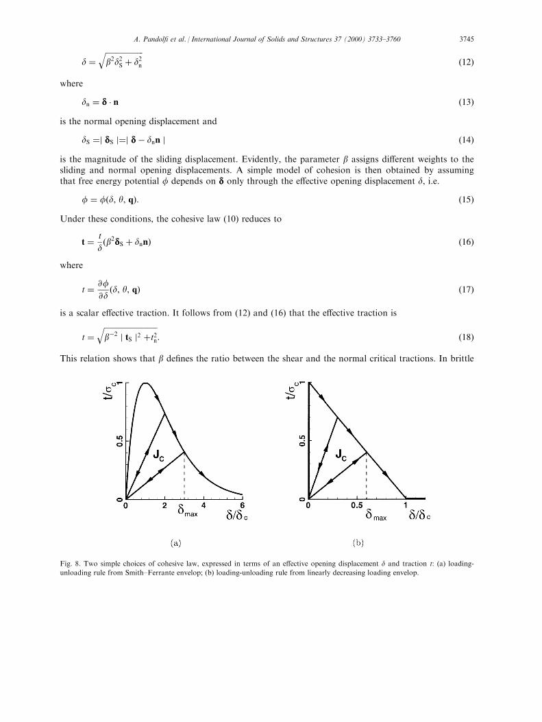
Fig. 8. Two simple choices of cohesive law, expressed in terms of an e�ective opening displacement d and traction t: (a) loading-
unloading rule from Smith±Ferrante envelop; (b) loading-unloading rule from linearly decreasing loading envelop.
A. Pandol® et al. / International Journal of Solids and Structures 37 (2000) 3733±3760 3745

materials, this ratio may be estimated by imposing lateral con®nement on specimens subjected to high-strain-rate axial compression (Chen and Ravichandran, 1994, 1996). Upon closure, the cohesive surfacesare subject to the contact unilateral constraint, including friction. Since the dropweight experimentalgeometry of interest here does not lead to signi®cant mode II sliding of the crack, we simply modelcrack closure in the spirit of penalty methods, i.e. by the introduction of a small surface compliance.
Fig. 8 depicts the particular type of irreversible cohesive laws envisioned here. Irreversibility manifestsitself upon unloading. Therefore, an appropriate choice of internal variable is the maximum attainede�ective opening displacement dmax. Loading is then characterized by the conditions: d=dmax and _dr0:Conversely, we shall say that the cohesive surface undergoes unloading when it does not undergoloading. We assume the existence of a loading envelop de®ning a relation between t and d underconditions of loading. A simple and convenient relation is furnished by Smith and Ferrante's universalbinding law, Fig. 8(a), or by the linearly decreasing envelop shown in Fig. 8(b). Following Camacho andOrtiz (1996) we shall assume unloading to the origin, Fig. 8, giving
t � tmax
dmax
d, if d < dmax or _d < 0: �19�
For the present model, the kinetic relations (11) reduce to a straightforward computation of dmax. Inorder to measure the extent of decohesion, we shall ®nd it convenient to introduce a damage parameter
D � f�dmax �Gc
: �20�
Evidently, D ranges from 0 to 1, with these limits corresponding to an uncracked solid and a fullyformed new surface, respectively. Furthermore, we require that
_Dr0 �21�
as be®ts the irreversibility of damage.A particularly appealing aspect of cohesive laws as models of fracture is that they ®t naturally within
the conventional framework of ®nite element analysis. One possible approach is to implement the
Fig. 9. Geometry of cohesive element. The surfaces Sÿ and S+ coincide in the reference con®guration of the solid.
A. Pandol® et al. / International Journal of Solids and Structures 37 (2000) 3733±37603746

cohesive law as a mixed boundary condition, relating tractions to displacements at boundaries orinterfaces (Hillerborg et al., 1976; Carpinteri, 1986; Needleman, 1987, 1990a, b, 1992; Planas et al., 1994;Tvergaard and Hutchinson, 1993, 1996a, b). Here, by contradistinction, we follow Willam (1989), Ortizand Suresh (1993) and Xu and Needleman (1994), and directly embed the cohesive law into surface-like®nite elements, leading to the formulation of so-called `cohesive' elements. In addition, we followCamacho and Ortiz (1996) and adaptively create new surface as required by the cohesive model byduplicating nodes along previously coherent element boundaries. The introduction of cohesive surfacesmay result in drastic changes in the topology of the model (Pandol® and Ortiz, 1999). The nodes aresubsequently released in accordance with a tension-shear cohesive law.
The geometry of the cohesive elements considered here is shown in Fig. 9. The element consists oftwo six-node triangles endowed with quadratic displacement interpolation. Fig. 10 also demonstrates thecompatibility between the cohesive elements and ten-node volume elements. Inserting the displacementinterpolation into the virtual work expression (7) leads to a system of semi-discrete equations of motionof the form:
MÈx� f int�x� � fext�t� �22�where x is the array of nodal coordinates, M is the mass matrix, fext is the external force array, and fint
is the internal force array. In calculations we use the second-order accurate central di�erence algorithmto discretize (22) in time (Belytschko, 1983; Hughes, 1983, 1987). Despite the fact that the time step isbounded by stability (Hughes, 1983), explicit integration is particularly attractive in three-dimensionalcalculations, where implicit schemes lead to system matrices which often exceed the available in-corestorage capacity. Yet another advantage of explicit algorithms is that they are ideally suited forconcurrent computing (Mathur et al., 1996).
4. Numerical tests and comparison with experiment
We have conducted detailed simulations of one of the drop-weight dynamic fracture tests described inthe foregoing. We take this test as a convenient yet exacting validation problem for assessing the ®delity
Fig. 10. 3D assembling of a 12-nodes triangular cohesive element with 10-nodes tetrahedra.
A. Pandol® et al. / International Journal of Solids and Structures 37 (2000) 3733±3760 3747

of cohesive models in applications involving dynamic fracture. In particular, simulations of the drop-weight test e�ectively probe the ability of cohesive theories of fracture to track dynamically initiatingand growing three-dimensional cracks in solids undergoing ®nite plastic deformations and heating. Theassumed test con®guration is shown in Fig. 11. A rectangular three-point bend specimen is subjected to
Fig. 12. Material parameters for C300 steel adopted in the numerical calculations. The material is assumed to obey J2-plasticity
with power-law hardening, rate dependency and linear thermal softening (e.g. CuitinÄ o and Ortiz, 1992; Marusich and Ortiz, 1995;
Camacho and Ortiz, 1997). The temperature ®eld is calculated locally assuming adiabatic conditions.
Fig. 11. Geometry of three-point bend test specimen.
A. Pandol® et al. / International Journal of Solids and Structures 37 (2000) 3733±37603748

dynamic loading as imparted by a falling weight which strikes at the midsection of the specimen. Thespecimen has an initial precrack 2.54 cm deep within its midsection sharpened by fatigue, Fig. 11.
The e�ect of the falling weight is approximated by prescribing a constant velocity of 10 m/s at thepoint of contact. Because of the impulsive nature of the motion, the problem is ideally suited to explicitdynamics. In explicit calculations a cohesive law of the form shown in Fig. 8(b) is preferable to a law ofthe Smith±Ferrante type, Fig. 8(a), as the initial elastic slope in the latter may place stringentrestrictions on the stable time step for explicit integration. The material Ð brittle C300 steel Ð isassumed to obey J2-plasticity with power-law hardening and rate dependency, as well as linear thermalsoftening. The temperature ®eld is calculated locally assuming adiabatic conditions (e.g. CuitinÄ o andOrtiz, 1992; Marusich and Ortiz, 1995; Camacho and Ortiz, 1997). The volume elements are 10-nodequadratic tetrahedra and the state variables are updated by recourse to the method of extension ofCuitinÄ o and Ortiz (1992). In view of the brittleness of the C300 steel under consideration, the extent ofshear lip formation may be expected to be small. Consequently, the crack surface may be approximatedas remaining essentially planar and con®ned to the midsection of the specimen. In order to allow fordynamic crack growth, we tile the midsection of the specimen with cohesive elements such as describedabove. Fig. 12 collects the material parameters employed in the calculations. The constitutive materialparameters have been obtained in-house, by means of Kolsky bar experiments performed on C300 steelspecimens of the same batch and heat treatment as those used in the fracture experiments. The quasi-static fracture parameters (KIC, GC) have been established by using fracture specimens of the samegeometry as in the dynamic tests loaded hydraulically in a three point bend con®guration.
The computational meshes are shown in Figs. 13 and 14. The meshes are designed so as to be ®neand nearly uniform on and in the vicinity of the crack plane, and to gradually coarsen away from the
Fig. 13. Overall view and detail of the crack plane corresponding to a coarse ®nite element mesh comprising 6280 nodes, 3410 tet-
rahedra and 130 cohesive elements.
A. Pandol® et al. / International Journal of Solids and Structures 37 (2000) 3733±3760 3749

crack plane up to a large uniform mesh size. All surfaces and the interior of the specimen are meshedautomatically by an advancing front method (Radovitzky and Ortiz, 1998). In order to investigate thein¯uence of mesh size, we have considered a coarse mesh, which contains 6280 nodes, 3410 tetrahedraand 130 cohesive elements; and a ®ne mesh comprising 42,428 nodes, 26,110 tetrahedra and 704cohesive elements. The minimum mesh size in the ®ne mesh is 0.4 mm, which reasonably resolves thecohesive zone size. Based on this dimension and the elastic moduli, a stable time step for explicit
Fig. 14. Overall view and detail of the crack plane corresponding to a ®ne ®nite element mesh comprising 42,428 nodes, 26,110 tet-
rahedra and 704 cohesive elements.
Fig. 15. Deformed geometry of the specimen after 2.4 ms.
A. Pandol® et al. / International Journal of Solids and Structures 37 (2000) 3733±37603750

Fig. 16. (a) Experimental (black) and numerical (gray) crack tip trajectories. (b) Crack-tip velocity computed by a three-point nu-
merical di�erentiation formula. Calculations done using coarse mesh of Fig. 13.
A. Pandol® et al. / International Journal of Solids and Structures 37 (2000) 3733±3760 3751

integration may conservatively be estimated as Dt=0.005 ms. The dynamic analysis starts at impact andits duration is 200 ms, or a total of 40,000 time steps.
The deformed mesh for the coarse model is shown to scale in Fig. 15 after the passage of 2.4 ms. Atthis time, the specimen is clearly split into two identical fragments. The ®nite rotations undergone by thespecimen should be carefully noted, as they demonstrate the need to account for ®nite kinematics in thecalculations. It is also interesting to note that the temperature rise is con®ned to a narrow zone
Fig. 17. Level contours of the damage variable D showing di�erent stages of crack growth (Dt = 10 ms). Calculations done using
®ne mesh of Fig. 14.
Fig. 18. Level contours of the equivalent plastic strain at di�erent stages of crack growth (Dt=10 ms), showing the development of
shear lips near the lateral surfaces. Calculations done using ®ne mesh of Fig. 14.
A. Pandol® et al. / International Journal of Solids and Structures 37 (2000) 3733±37603752

surrounding the crack tip, and to the region of contact between the specimen and the impactor, whereplastic deformations are large. Indeed, as the falling weight strikes the specimen, it deeply indents thetop surface, with the result that as the crack approaches the surface it encounters material which hasbeen prestressed plastically.
The ability of the cohesive elements to simulate the emergence of the crack through the upper surfaceof the specimen is noteworthy. As the crack approaches the surface, the ligament diminishes steadilyand eventually becomes comparable in size with the plastic zone, at which point the small-scale yieldingcondition breaks down. The situation is further compounded by the fact that the region where the crackcuts through the top surface is plastically prestrained by the weight, a circumstance which in¯uences thepropagation of the crack. It is therefore noteworthy that a single description of the fracture behavior ofthe material, supplied by the cohesive model, e�ectively governs all phases of the growth of the crack,including crack-growth initiation, propagation, both in the interior of the specimen and at the specimenlateral surface, and the intersection of the crack and upper surface. By way of sharp contrast, within theconventional fracture mechanics framework exempli®ed by the fracture criterion (1), each of theseaspects of crack growth requires a di�erent ad hoc criterion tuned to the prevailing conditions ofdeformation, which greatly increases the degree of empiricism of the formulation.
The numerical and experimental trajectory and speed of the central point of the crack front areplotted in Fig. 16. It is evident from Fig. 16(a) that the cohesive model matches the point of crack-growth initiation and the subsequent trajectory of the crack remarkably well. The velocity history of thecrack front as computed by a three-point numerical di�erentiation formula is shown in Fig. 16(b). Theagreement between simulation and observation is as good as may be expected when derivatives ofprimitive quantities are computed. Again, it should be carefully noted that the velocity of the crack tipis an outcome of the calculation and is not in any way built into the model a priori.
Fig. 19. (a) Experimental fracture surface. (b) Level contours of equivalent plastic strain 0.2 ms after impact. Calculations done
using ®ne mesh of Fig. 14.
A. Pandol® et al. / International Journal of Solids and Structures 37 (2000) 3733±3760 3753

Details of the crack growth process are shown in Figs 17±19. Fig. 17 depicts contours of the damage
variable D, Eq. (20), at di�erent stages of growth. A value of D = 0 denotes the absence of cracking,
whereas the limiting value of D = 1 denotes a fully formed crack. The narrow transition zone between
these two limiting values may be regarded as a smeared crack tip, or cohesive zone. It is observed in
Fig. 17 that the crack front develops a small curvature as it propagates and it lags behind somewhat
near the free surface as a consequence of enhanced plastic activity in that region (tunneling). This
enhanced plastic activity is clearly evident in Fig. 18, which shows the contours of the equivalent plastic
strain. A direct comparison of the computed plastic activity and the experimentally observed plastic
surface is also shown in Fig. 19. As expected the plastic zone is markedly larger near the free surface,
Fig. 19(b), as a consequence of the attendant loss of constraint and the emergence of shear lips,
Fig. 19(a). The good agreement between the observed size of the shear lips and the computed zone of
enhanced plastic activity near the surface is noteworthy.
While these features are relatively weak in C300 steel, as be®ts the brittleness of the material, they
nevertheless serve to illustrate the point that the shielding e�ect of plasticity and the attendant
retardation of the crack tip are indeed predicted by the simulations. Furthermore, it should be noted
that such e�ects are not built into the fracture criterion a priori, but rather follow naturally from the
explicit consideration of plasticity over multiple length scales, including the scale of the near tip ®elds.
A sensitivity analysis of the crack-tip trajectory to the fracture toughness KIc, the cohesive strength sc,and the ratio b=KIIc/KIc is shown in Figs. 20±22. As may be seen from Fig. 20, the main e�ect of an
increase (decrease) in KIc is to retard (anticipate) the crack-growth initiation time. Interestingly, the
e�ect of a variation in KIc on the crack propagation velocity is negligible by comparison, Fig. 20.
Similarly, an increase (decrease) in the cohesive strength sc retards (anticipates) the crack-growth
Fig. 20. Sensitivity of the crack tip trajectory to variations in the fracture toughness KIc. Calculations done using coarse mesh of
Fig. 13.
A. Pandol® et al. / International Journal of Solids and Structures 37 (2000) 3733±37603754
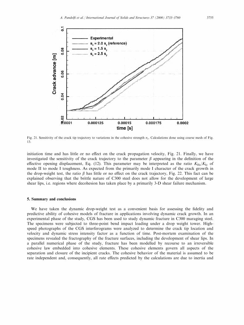
initiation time and has little or no e�ect on the crack propagation velocity, Fig. 21. Finally, we haveinvestigated the sensitivity of the crack trajectory to the parameter b appearing in the de®nition of thee�ective opening displacement, Eq. (12). This parameter may be interpreted as the ratio KIIc/KIc ofmode II to mode I toughness. As expected from the primarily mode I character of the crack growth inthe drop-weight test, the ratio b has little or no e�ect on the crack trajectory, Fig. 22. This fact can beexplained observing that the brittle nature of C300 steel does not allow for the development of largeshear lips, i.e. regions where decohesion has taken place by a primarily 3-D shear failure mechanism.
5. Summary and conclusions
We have taken the dynamic drop-weight test as a convenient basis for assessing the ®delity andpredictive ability of cohesive models of fracture in applications involving dynamic crack growth. In anexperimental phase of the study, CGS has been used to study dynamic fracture in C300 maraging steel.The specimens were subjected to three-point bend impact loading under a drop weight tower. High-speed photographs of the CGS interferograms were analyzed to determine the crack tip location andvelocity and dynamic stress intensity factor as a function of time. Post-mortem examination of thespecimens revealed the fractography of the fracture surfaces, including the development of shear lips. Ina parallel numerical phase of the study, fracture has been modelled by recourse to an irreversiblecohesive law embedded into cohesive elements. These cohesive elements govern all aspects of theseparation and closure of the incipient cracks. The cohesive behavior of the material is assumed to berate independent and, consequently, all rate e�ects predicted by the calculations are due to inertia and
Fig. 21. Sensitivity of the crack tip trajectory to variations in the cohesive strength sc. Calculations done using coarse mesh of Fig.
13.
A. Pandol® et al. / International Journal of Solids and Structures 37 (2000) 3733±3760 3755

the rate dependency in plastic deformation. The ®nite element model is three dimensional and consistsof quadratic ten-noded tetrahedra. The numerical models were calibrated by means of experimentallyobtained constitutive and cohesive law parameters.
The numerical simulations have proven highly predictive of a number of observed features,including: the crack growth initiation time; the trajectory of the propagating crack tip; and theformation of shear lips near the lateral surfaces. These features follow naturally from a singledescription of the fracture properties of the material, supplied by the cohesive law, and are notbuilt in piecemeal into the model. By separately accounting for plasticity, inertia and thermale�ects, the description of the fracture behavior may focus sharply on the separation processesresponsible for the creation of new surface, which considerably cuts down on the level ofphenomenology of the theory. In this particular sense, the fracture model and the bulk constitutiverelations constitute truly independent mechanical postulates. In particular, the applicability of thetheory is not restricted by the type of bulk behavior, the geometry of the specimen and loading,the size of the plastic region or the presence or absence of inertia.
It should also be noted that the use of cohesive theories in calculations relies strongly on the ability toresolve multiple length scales simultaneously. Thus, Camacho and Ortiz (1996) have also shown thatmesh-size independent results are obtained when the mesh adequately resolves the cohesive zone, whichtends to be small in typical materials. Recent advances in automatic meshing, mesh adaption andcomputer hardware have contributed to making the type of multiscale analysis called for by cohesivemodels increasingly feasible. In this particular sense, cohesive models of fracture partake of the presentemphasis on physics-based multiscale analysis of materials, an emphasis which may only be expected tobe a�rmed in the future.
Fig. 22. Sensitivity of the crack tip trajectory to variations in the ratio b=KIIc/KIc. Calculations done using coarse mesh of Fig. 13.
A. Pandol® et al. / International Journal of Solids and Structures 37 (2000) 3733±37603756

Acknowledgements
The support of the O�ce of Naval Research through grant N00014-95-1-0453 is gratefullyacknowledged.
References
Angelino, G.C., 1978. In¯uence of the geometry on unstable crack extension on determination of dynamic fracture mechanics
parameters. In Testing, A. S. and Materials, editors, Fast Fracture and Crack Arrest, volume ASTM STP 627, pp. 392±407.
Atluri, S.N., Nishioka, T., 1983. Path-independent integrals, energy release rates and general solutions of near tip ®elds in mixed
mode dynamic fracture mechanics. Engineering Fracture Mechanics 28, 1±22.
Barrenblatt, G.I., 1962. The mathematical theory of equilibrium of cracks in brittle fracture. Advances in Applied Mechanics 7,
55±129.
Beinert, J., Kaltho�, J.F., 1981. Experimental determination of dynamic stress intensity factors by shadow patterns. In: Sih, G.
(Ed.), Mechanics of Fracture, vol. VII. Sijtho� and Noordho�, pp. 281±330.
Beltz, G.E., Rice, J.R. 1991. Dislocation nucleation versus cleavage decohesion at crack tips. In: Lowe, T.C., Rollett, A.D.,
Follansbee, P.S., Daehn, G.S. (Eds.), Modeling the Deformation of Crystalline Solids: Physical Theory, Application and
Experimental Comparisons. Warrendale, PA, pp. 457±480 TSM-AIME.
Belytschko, T. 1983. An overview of semidiscretization and time integration procedures. In: Belytschko, T., Hughes, T.J.R. (Eds.),
Computational Methods for Transient Analysis. North-Holland, pp. 1±65.
Bilek, Z., 1980. Some comments on dynamic crack propagation in a high strength steel. In Testing, A. S. and Materials, editors,
Crack Arrest Methodology and Applications, volume ASTM STP 711, pp. 240±247.
Bradley, W.B., Kobayashi, A.S., 1970. An investigation of propagating cracks by dynamic photoelasticity. Experimental Mechanics
10, 106±113.
Brickstad, B., 1983. A fem analysis of crack arrest experiments. International Journal of Fracture 21, 177±194.
Camacho, G.T., Ortiz, M., 1996. Computational modelling of impact damage in brittle materials. International Journal of Solids
and Structures 33 (2022), 2899±2938.
Camacho, G.T., Ortiz, M., 1997. Adaptive Lagrangian modelling of ballistic penetration of metallic targets. Computer Methods in
Applied Mechanics and Engineering 142, 269±301.
Carpinteri, A., 1986. Mechanical Damage and Crack Growth in Concrete. Martinus Nijho�, Dordrecht, The Netherlands.
Chen, W.N., Ravichandran, G., 1994. Dynamic compressive behavior of ceramics under lateral con®nement. Journal de Physique
IV 4, 177±182.
Chen, W.N., Ravichandran, G., 1996. Static and dynamic compressive behavior of aluminum nitride under moderate con®nement.
Journal of the American Ceramic Society 79, 579±584.
Chona, R., Irwin, G.R., Sanford, R.J., 1983. In¯uence of specimen size and shape on the singularity dominated zone. In: Lewis,
J.C., Sines, G. (Ed.). Fracture Mechanics: 14th Symposium Volume I. Theory and Analysis, ASTM STP 791, pp. I/3±I/23.
Chona, R., Sanford, R.J., 1988. Analyzing crack tip isochromatic fringe patterns. In VI International Congress of Experimental
Mechanics, pp. 751±760.
CuitinÄ o, A.M., Ortiz, M., 1992. A material-independent method for extending stress update algorithms from small-strain plasticity
to ®nite plasticity with multiplicative kinematics. Engineering Computations 9, 437±451.
Dally, J.W., 1979. Dynamic photoelastic studies of fracture. Experimental Mechanics 19, 349±361.
Dally, J.W., Fourney, W.G., Irwin, G.R., 1985. On the uniqueness of kID±a.relation. International Journal of Fracture 27, 159±
168.
De-Andre s, A., Pe rez, J.L., Ortiz, M., 1998. Elastoplastic ®nite element analysis of three-dimensional fatigue crack growth in
aluminum shafts subjected to axial loading. International Journal of Solids and Structures. In press.
Dugdale, D.S., 1960. Yielding of steel sheets containing slits. Journal of the Mechanics and Physics of Solids 8, 100±104.
Freund, L.B., 1972. Crack propagation in an elastic solid subjected to general loading-i constant rate extension. Journal of the
Mechanics and Physics of Solids 20, 129±140.
Freund, L.B., 1990. Dynamic Fracture Mechanics. Cambridge University Press, Cambridge.
Freund, L.B., Douglas, A.S., 1982. The in¯uence of inertia on elastic-plastic antiplane-shear crack growth. Journal of the
Mechanics and Physics of Solids 30, 59±74.
Freund, L.B., Hutchinson, J.W., 1985. High strain-rate crack growth in rate-dependent plastic solids. Journal of the Mechanics
and Physics of Solids 33, 169±191.
Freund, L.B., Hutchinson, J.W., Lam, P.S., 1986. Analysis of high strain rate elastic-plastic crack growth. Engineering Fracture
Mechanics 23, 119±129.
A. Pandol® et al. / International Journal of Solids and Structures 37 (2000) 3733±3760 3757
Freund, L.B., Rosakis, A.J., 1992. The structure of the near tip ®eld solution during transient elastodynamic crack growth. Journal
of the Mechanics and Physics of Solids 40, 699±719.
Goldsmith, W., Katsamanis, F., 1979. Fracture of notched polymeric beams due to central impact. Experimental Mechanics 18,
235±244.
Grady, D.E., Benson, D.A., 1983. Fragmentation of metal rings by electromagnetic loading. Experimental Mechanics 23, 393±400.
Hillerborg, A., Modeer, M., Petersson, P.E., Needleman, A., 1976. Analysis of crack formation and crack growth in concrete by
means of fracture mechanics and ®nite elements. Cement Concrete Resarch 6, 773±782.
Hughes, T.J.R. 1983. Analysis of transient algorithms with particular reference to stability behavior. In: Belytschko, T., Hughes,
T.J.R. (Eds.), Computational Methods for Transient Analysis. North-Holland, pp. 67±155.
Hughes, T.J.R., 1987. The Finite Element Method: Linear Static and Dynamic Finite Element Analysis. Prentice-Hall, Englewood
Cli�s, NJ.
Irwin, G.R., 1958. In Proceedings of SESA, volume 16, pp. 93±96.
Irwin, G.R., Dally, J.W., Kobayashi, T., Fourney, W.L., Etheridge, M.J., Rossmanith, H.P., 1979. On the determination of the a.-
K relationship for birefringent polymers. Experimental Mechanics 19, pp. 121±128.
Kaltho�, J.F., 1985. On the measurement of dynamic fracture toughness Ð a review of recent work. International Journal of
Fracture 27, 277±298.
Kaltho�, J.F., Beinert, J., Winkler, S., 1978. In¯uence of dynamic e�ects on crack arrest. Technical report, Institut fur
Festkorpermechanik.
Kaltho�, J.F., Winkler, S., Beinert, J., 1976. Dynamic stress intensity factors for arresting cracks in DCB specimens. International
Journal of Fracture 12, 317±319.
Kanazawa, T., Machida, S., Teramoto, T., Yoshinari, H., 1981. Study on fast fracture and crack arrest. Experimental Mechanics
21 pp. 78±88.
Katsamanis, F., Raftopoulos, D., Theocaris, P.S., 1977. Static and dynamic stress intensity factors by the method of transmitted
caustics. Journal of Engineering Materials and Technology 99, 105±109.
Knauss, W.G., Ravi-Chandar, K., 1985. Some basic problems in stress wave dominated fracture. International Journal of Fracture
27, 127±143.
Kobayashi, A.S., 1978. Investigation of Transient E�ects for Dynamically Initiating and Growing Cracks Under Stress Wave
Loading Conditions. University Press, Virginia, pp. 481±496.
Kobayashi, T., Dally, J.W., 1980. Dynamic photoelastic determination of the a.-K relation for 4340 alloy steel. In: Hahn, G.T.,
Kanninen, M.F. (Eds.), Crack Arrest Methodology and Applications, vol. ASTM STP 711, pp. 189±210.
Krishnaswamy, S., Rosakis, A.J., 1990. On the extent of dominance of asymptotic elastodynamic crack tip ®elds: Part I Ð an
experimental study using bifocal caustics. Journal of Applied Mechanics 58, 87±94.
Krishnaswamy, S., Rosakis, A.J., Ravichandran, G., 1991. On the extent of dominance of asymptotic elastodynamic crack tip
®elds: Part II Ð numerical investigation of three dimensional and transient e�ects. Journal of Applied Mechanics 58, 95±103.
Krishnaswamy, S., Tippur, H.V., Rosakis, A.J., 1992. Measurement of transient crack tip deformation ®elds using the method of
cgs. Journal of the Mechanics and Physics of Solids 40, 339±372.
Lam, P.S., Freund, L.B., 1984. Analysis of dynamic growth of a tensile crack in an elastic±plastic material. Journal of the
Mechanics and Physics of Solids 33, 153±167.
Liu, C., Rosakis, A.J., Freund, L.B., 1993. The interpretation of optical caustics in the presence of non-uniform crack tip motion
histories: a study based on a higher order transient crack tip expansion. International Journal of Solids and Structures 30, 875±
897.
Lubliner, J., 1972. On the thermodynamic foundations of non-linear solid mechanics. International Journal of Non-Linear
Mechanics 7, 237±254.
Lubliner, J., 1973. On the structure of the rate equations of materials with internal variables. Acta Mechanica 17, 109±119.
Marsden, J.E., Hughes, T.J.R., 1983. Mathematical Foundations of Elasticity. Prentice-Hall, Englewood Cli�s, NJ.
Marusich, T.D., Ortiz, M., 1995. Modelling and simulation of high-speed machining. International Journal for Numerical Methods
in Engineering 38, 3675±3694.
Mathur, K.K., Needleman, A., Tvergaard, V., 1996. Three dimensional analysis of dynamic ductile crack growth in a thin plate.
Journal of the Mechanics and Physics of Solids 44, 439±464.
McClintock, F., Irwin, G.R., 1964. Fracture toughness testing and applications, volume ASTM STP 381, p. 95.
Needleman, A., 1987. A continuum model for void nucleation by inclusion debonding. Journal of Applied Mechanics 54, 525±531.
Needleman, A., 1990a. An analysis of decohesion along an imperfect interface. International Journal of Fracture 42, 21±40.
Needleman, A., 1990b. An analysis of tensile decohesion along an interface. Journal of the Mechanics and Physics of Solids 38 (3),
289±324.
Needleman, A., 1992. Micromechanical modeling of interfacial decohesion. Ultramicroscopy 40, 203±214.
Ortiz, M., 1988. Microcrack coalescence and macroscopic crack growth initiation in brittle solids. International Journal of Solids
and Structures 24, 231±250.
A. Pandol® et al. / International Journal of Solids and Structures 37 (2000) 3733±37603758

Ortiz, M., 1996. Computational micromechanics. Computational Mechanics 18, 321±338.
Ortiz, M., Pandol®, A., 1999. A class of cohesive elements for the simulation of three-dimensional crack propagation. International
Journal for Numerical Methods in Engineering 44, 1267±1282.
Ortiz, M., Suresh, S., 1993. Statistical properties of residual stresses and intergranular fracture in ceramic materials. Journal of
Applied Mechanics 60, 77±84.
Owen, D.M., Zhuang, S., Rosakis, A.J., Ravichandran, G., 1998. Experimental determination of dynamic crack initiation and
propagation fracture toughness in thin aluminum sheets. International Journal of Fracture 90, 153±174.
Pandol®, A., Krysl, P., Ortiz, M., 1999. Finite element simulation of ring expansion and fragmentation: the capturing of length
and time scales through cohesive models of fracture. International Journal of Fracture. In press.
Pandol®, A., Ortiz, M., 1999. Solid modeling aspects of three-dimensional fragmentation. Engineering with Computers 14, 287±
308.
Planas, J., Elices, M., Guinea, G.V. 1994. Cohesive cracks as a solution of a class of nonlocal problems. In: Bazant, Z.P. (Ed.),
Fracture and Damage in Quasibrittle Structures. Experiment, Modelling and Computer Analysis. E & FN SPON.
Radovitzky, R., Ortiz, M., 1998. Tetrahedral mesh generation based on node insertion in crystal lattice arrangements and
advancing-front-Delaunay triangulation. Computer Methods in Applied Mechanics and Engineering. In press.
Ravi-Chandar, K., Knauss, W.G., 1983. Dynamic crack tip stresses under stress wave loading Ð a comparison of theory and
experiment. International Journal of Fracture 20, 209±222.
Ravi-Chandar, K., Knauss, W.G., 1984a. An experimental investigation into dynamic fracture, Part 1. Crack initiation and arrest.
International Journal of Fracture 25 (4), 247±262.
Ravi-Chandar, K., Knauss, W.G., 1984b. An experimental investigation into dynamic fracture, Part 2. Microstructural aspects.
International Journal of Fracture 26 (1), 65±80.
Ravi-Chandar, K., Knauss, W.G., 1984c. An experimental investigation into dynamic fracture, Part 3. On steady state crack
propagation and crack branching. International Journal of Fracture 26 (2), 141±154.
Ravi-Chandar, K., Knauss, W.G., 1984d. An experimental investigation into dynamic fracture, Part 4. On the interaction of stress
waves with propagating cracks. International Journal of Fracture 26 (3), 189±200.
Rice, J.R. 1968. Mathematical analysis in the mechanics of fracture. In: Liebowitz, H. (Ed.), Fracture. Academic Press, pp. 191±
311.
Rice, J.R., 1992. Dislocation nucleation from a crack tip: an analysis based on the Peierls concept. Journal of the Mechanics and
Physics of Solids 40, 235±271.
Rosakis, A.J., 1980. Analysis of the optical method of caustics for dynamic crack propagation. Engineering Fracture Mechanics
13, 331±347.
Rosakis, A.J. 1993. Two optical techniques sensitive to gradients of optical path di�erence: the method of caustics and the
coherent gradient sensor (CGS). In: Epstein, J. (Ed.), Experimental Techniques in Fracture. VCH, New York, pp. 327±425.
Rosakis, A.J., Du�y, J., Freund, L.B., 1984. The determination of dynamic fracture toughness of aisi 4340 steel by the shadow
spot method. Journal of the Mechanics and Physics of Solids 32, 443±460.
Rosakis, A.J., Liu, C., Freund, L.B., 1991. A note on the asymptotic stress ®eld of a non-uniformly propagating dynamic crack.
International Journal of Fracture 50, R39±R45.
Rosakis, A.J., Ravi-Chandar, K., 1986. On the crack tip stress state: An experimental evaluation of three dimensional e�ects.
International Journal of Solids and Structures 22, 121±134.
Rosakis, A.J., Zehnder, A.T., 1985. On the dynamic fracture of structural metals. International Journal of Fracture 27, 169±186.
Rosakis, A.J., Zehnder, A.T., Narasimhan, R., 1988. Re¯ection and their application to elastic-plastic and dynamic fracture
mechanics. Optical Engineering 27, 596±610.
Rose, J.H., Ferrante, J., Smith, J.R., 1981. Universal binding energy curves for metals and bimetallic interfaces. Physical Review
Letters 47 (9), 675±678.
Sanford, R.J., Chona, R., 1984. Photoelastic calibration of the short-bar chevron notched specimen. In: Underwood, J.H.,
Freiman, S.W., Baratta, F.I. (Eds.), Chevron Notched Specimens: Testing and Stress Analysis, vol. ASTM STP 855, pp. 81±97.
Sanford, R.J., Dally, J.W., 1979. A general method for determining mixed mode stress intensity factors from isochromatic fringe
patterns. Engineering Fracture Mechanics 11, 621±633.
Shukla, A., Chona, R. 1988. The stress ®eld surrounding a rapidly propagating curving crack. In: Read, D.T., Reed, R.P. (Eds.),
Fracture Mechanics, 18th Symposium, volume ASTM STP 945, pp. 86±99.
Theocaris, P.S., 1978. Dynamic propagation and arrest measurements by the method of caustics on overlapping skew-parallel
cracks. International Journal of Solids and Structures 14, 639±653.
Tippur, H.V., Krishnaswamy, S., Rosakis, A.J., 1990. Coherent gradient sensor for crack tip deformation measurements: analysis
and experimental results. International Journal of Fracture 48, 193±204.
Tippur, H.V., Krishnaswamy, S., Rosakis, A.J., 1991. Optical mapping of crack tip deformations using the method of transmission
and re¯ection coherent gradient sensing: a study of crack tip k-dominance. International Journal of Fracture 52, 91±117.
A. Pandol® et al. / International Journal of Solids and Structures 37 (2000) 3733±3760 3759

Tvergaard, V., Hutchinson, J.W., 1993. The in¯uence of plasticity on mixed-mode interface toughness. Journal of the Mechanics
and Physics of Solids 41, 1119±1135.
Tvergaard, V., Hutchinson, J.W., 1996a. E�ect of strain dependent cohesive zone model on predictions of interface crack growth.
Journal de Physique IV 6, 165±172.
Tvergaard, V., Hutchinson, J.W., 1996b. E�ect of strain dependent cohesive zone model on predictions of crack growth resistance.
International Journal of Solids and Structures 33, 3297±3308.
Willam, K. 1989. Simulation issues of distributed and localized failure computations. In: Mazars, J., Bazant, Z.P. (Eds.), Cracking
and Damage. Elsevier, New York, pp. 363±378.
Xu, X.P., Needleman, A., 1993. Void nucleation by inclusion debonding in a crystal matrix. Modelling and Simulation in
Materials Science and Engineering 1, 111±132.
Xu, X.P., Needleman, A., 1994. Numerical simulations of fast crack growth in brittle solids. Journal of the Mechanics and Physics
of Solids 42, 1397±1434.
Xu, X.P., Needleman, A., 1995. Numerical simulations of dynamic interfacial crack growth allowing for crack growth away from
the bond line. International Journal of Fracture 74, 253±275.
Xu, X.P., Needleman, A., 1996. Numerical simulations of dynamic crack growth along an interface. International Journal of
Fracture 74, 289±324.
Zehnder, A.T., Rosakis, A.J., 1986. A note on the measurement of K and J under small scale yielding conditions using the method
of caustics. International Journal of Fracture 30, R43±R48.
Zehnder, A.T., Rosakis, A.J., 1990. Dynamic fracture initiation and propagation in 4340 steel under impact loading. International
Journal of Fracture 43, 271±285.
A. Pandol® et al. / International Journal of Solids and Structures 37 (2000) 3733±37603760