threaded inserts “t
TRANSCRIPT

“t
ND
UST
RlA
LT
HR
EA
DE
DIN
SER
TS
S
ifI
xw
C4C
%4C
’)
2,v1:wa:
:D:ø
::Ø
w::a:
Q::a:
!::a:
iw
::0
O:O
,--o
wo
co
øw
—zFmiJQ
øw
wxiO
>O
W
ICC
1W0
IDwtz
0-J-JCl)z00
0z0xCl)
w-Jcoz0a:
LUC.)zzLUIz
I
INTRODUCTIONRead manual before operating tool.You now own the finest insert installation tool on the market today. These durable tools provide many years of trouble freeoperation if you will simply follow the instructions in this manual.
Prior to use, certain checks must be made. This tool requires the proper air line setup, lubrication, and air pressure to set thedesired inserts.
AIR LINE SET UPEvery ARO Air Tool is designed and built to yield the longest possible useful life, with a minimum amount of servicing. Since an airtool is a precision machine whose working parts mate with close tolerances, it should receive the same reasonable care as anyother machine tool. Here are a few simple practices that will keep your ARO Air Tool in top operating condition.
KEEP AIR SUPPLY CLEAN. All compressed air carries varying amounts of dust, scale, moisture and other foreign matter thatshould be removed by proper filtering. Failure to keep air supply clean will result in excessive wear on working parts. Therefore.we recommend the installation of an air line filter. If your tool is equipped with a built-in air strainer, remove and clean the strainerperiodically. Always blowout the air hose before attaching to tool.
LUBRICATIONUSE AIR LINE LUBRICATOR. Air tool motors operate at extremely high speeds. and must have proper oil lubrication. An air line
lubricator should be installed and oil supply properly regulated. Your ARO Distributor can furnish the correct combination air linefilter and oiler. Some units can service up to three tools simultaneously. As a further precaution, put a few drops of light oil in airinlet of tool before attaching tool to air line for the first time
RECOMMENDED LUBRICANTS: Spindle Oil 29665 (I qt. container) for oiler and air inlet.
FILTERED AND OILED AIR will allow the tool to operate more efficiently and yield a longer life to operating parts andmechanisms. A line filter capable of filtering particles larger than 50 microns should be used with a line oiler.
FILTER-REGULATOR-OILER combination (F-R-L) Model 28231-810 is recommended for use with this Air Tool. The capacity ofthe individual Filter-Oiler is adequate to provide clean (40 micron), oiled and regulated air for the tool AIR CONSUMPTION:Approximately 25 SCFM.
RECOMMENDED HOSE SIZE: 5/16’ nominal inside diameter.
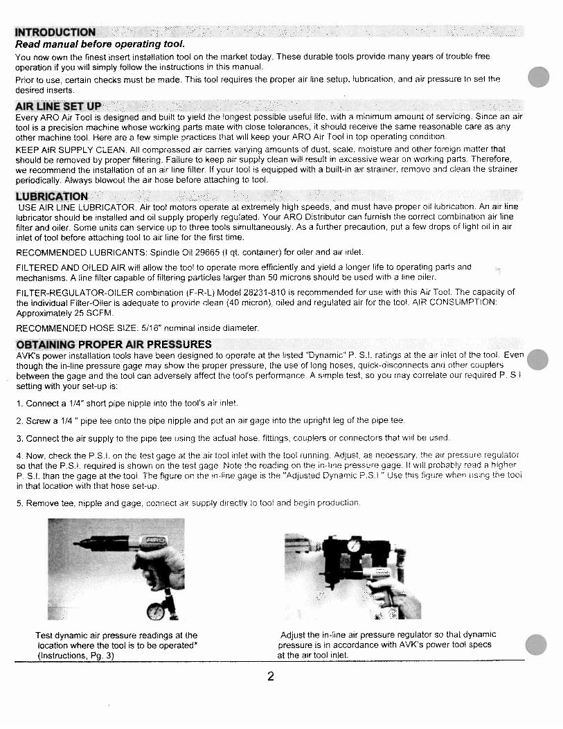
OBTAINING PROPER AIR PRESSURESAVK’s power installation tools have been designed to operate at the listed ‘Dynamic’ P. S.l. ratings at the air inlet of the tool. Eventhough the in-line pressure gage may show the proper pressure. the use of long hoses. quick-disconnects and other couplersbetween the gage and the tool can adversely affect the tools performance. A simple test, so you may correlate our required P SI.setting with your set-up is:
1. Connect a 1/4” short pipe nipple into the tool’s air inlet
2. Screw a 1/4” pipe tee onto the pipe nipple and put an air gage into the upright leg of the pipe tee.
3. Connect the air supply to the pipe tee using the actual hose. fittings. couplers or connectors that will be used
4. Now, check the PSI. on the test gage at the air tool inlet with the tool running. Adjust. as necessary. the air pressure reguiatorso that the P.S.l required is shown on the test gage Note the reading on the in-line pressure gage. It will probabi/ read a higherP. Si. than the gage at the tool The figure on the n-line gage is the “Adjusted Dynamic PSI’ Use this figure when using the tootin that location with that hose set-up
5. Remove tee. nipple and gage. connect air supply directly to tool and begr production
Test dynamic air pressure readings at the Adjust the in-line air pressure regulator so that dynamiclocation where the tool is to be operated* pressure is in accordance with AVK’s power tool specs(Instructions, Pg. 3) at the air tool inlet.
2
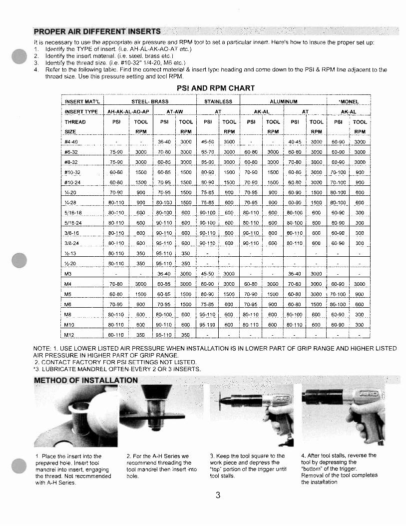
PROPER AIR DIFFERENT INSERTSIt is necessary to use the appropriate air pressure and RPM tool to set a particular insert. Heres how to insure the proper set up:1. Identify the TYPE of insert. (i.e AH-AL-AK-AO-AT etc.)2 Identify the insert material. (ie. steel, brass etc.)3 Identify the thread size. (i.e. #10-32” 1/4-20, M6 etc.)4 Refer to the following table. Find the correct material & insert type heading and come down to the PSI & RPM line adjacent to the
thread size. Use this pressure setting and tool RPM.
PSI AND RPM CHART
1. Place the insert into theprepared hole. Insert toolmandrel into insert, engagingthe thread. Not recommendedwith A-H Series.
2. For the A-H Series werecommend threading thetool mandrel then insert intohole.
3. Keep the tool square to thework piece and depress the“top” portion of the trigger untiltool stalls.
4. After tool stalls, reverse thetool by depressing the“bottom” of the trigger.Removal of the tool completesthe installation.
INSERT MAT’L STEEL- BRASS STAINLESS ALUMINUM “MONEL
INSERT TYPE AH-AK-AL-AO-AP AT-AW AT____ AK-AL AT____ AK-AL
THREAD PSI TOOL PSI TOOL PSI TOOL PSI TOOL PSI TOOL PSI TOOL
SIZE RPM RPM RPM RPM RPM RPM
#4-40 - - 36-40 3000 45-50 3000 - - 40-45 3000 60-90 3000
#6-32 75-90 3000 70-80 3000 65-70 3000 60-80 3000 60-80 3000 60-90 3000
#8-32 75-90 3000 60-85 3000 85-90 3000 60-80 3000 70-80 3000 60-90 . 3000
#10-32 60-80 1500 60-85 1500 80-90 1500 70-90 1500 60-80 3000 70-100 900
#10-24 60-80 1500 70-95 1500 80-90 1500 70-90 1500 60-80 3000 70-100 900
%-20 70-90 900 70-95 1500 75-85 600 70-95 900 60-90 1500 80-100 600
Y.-28 80-110 900 80-100 1500 75-85 600 70-95 900 60-90 1500 80-100 600
5/16-18 80-110 600 80-100 600 90-100 600 80-110 600 80-100 600 60-90 300
5/16-24 80-110 600 90-110 600 90-100 600 80-110 600 80-100 600 60-90 300
3/8-16 80-110 600 90-110 600 90-110 600 90-110 600 80-110 600 60-90 300
3/8-24 80-110 600 95-110 600 90-110 600 90-110 600 80-110 600 60-90 300
%-13 80-110 350 95-110 350 - - - - - - - -
%-20 80-110 350 95-110 350 - - - - - - - -
M3 - - 36-40 3000 45-50 3000 - - 36-40 3000 - -
M4 70-80 3000 60-85 3000 80-90 3000 60-80 3000 70-80 3000 60-90 3000
MS 60-80 1500 60-85 1500 80-90 1500 70-90 1500 60-80 3000 70-100 900
M6 70-90 900 70-95 1500 75-85 600 70-95 900 60-80 1500 80-100 600
M8 80-110 600 80-100 600 95-110 600 80-110 600 80-100 600 60-90 300
M10 80-110 600 90-110 600 95-110 600 80-110 600 80-110 600 60-90 300
M12 80-110 350 95-110 350 - - - - - - - -
NOTE; 1. USE LOWER LISTED AIR PRESSURE WHEN INSTALLATION IS IN LOWER PART OF GRIP RANGE AND HIGHER LISTEDAIR PRESSURE IN HIGHER PART OF GRIP RANGE.2 CONTACT FACTORY FOR PSI SETTINGS NOT LISTED.
*3 LUBRICATE MANDREL OFTEN-EVERY 2 OR 3 INSERTS.
METHOD OF INSTALLATIONI
3
_zZ*XZZES
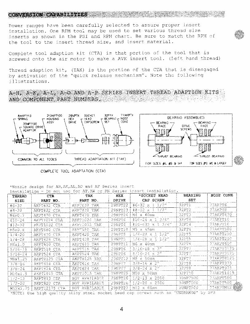
Power ranges have been carefully selected to assure proper insert
instaliation. One RPM tool may be used to set va1ious thread size
inserts as shown in the PSI and RPM chart. Be sure to match the RPM
the tool to the insert thread size, and insert material.
Complete tool adaption kit (CTA) is that portion of the tool that is
screwed onto the air motor to make a AVK insert oo1. (Left hand thread)
Thread adaption kit, (TAK) is the prrtion of the CTA that is disengaged
by activation of the “quick release mechanism”. Note the following
illustrations.
A—H, A-K, A-L, A-O AND A-P SERIES INSERT THREAD ADAPTION KITS
AND COMPONENT PART NUMBERS.
32PTh 77A1sPTX FAThNG NOSE GEARING ASSEMGLIEST BEARNC BEAR NC —
‘ RACE 7 DPV PACE
31U1-4RjST 8r4ThNO T1FIiS fE4NG
COMMON TO ALL TOOLS
____________
FOR SZES 4 %B &M4-- iAS fh45&1P1EP
COMPLETE TOOL ADAPTATION CTA,
Nozze deslQr. fc AH,AK,AL,AC a AP
1r:aazc — )c rot se AT,A5 t eres
T THREAD CTA TAK HEX *3KET HEAD LiINE CONE
I SIZE____ PARTNO. PART NO. DRIVE CAP_SCREW SET
___
AA?T CTA 3 AK x1AKPT832 A r?FPlL :r i#
14 A I Al 4 4 14h
: -
Th’-i 11P61 TA 4 j j — T -
nL i7fiZ- jJ’ ZJ
__
FPT81 r LZ I zLz__‘ 4 ZZ
A c1li - -
hc1h Jia 7 DI
—
THREAD ADAPTATION iIT I
4

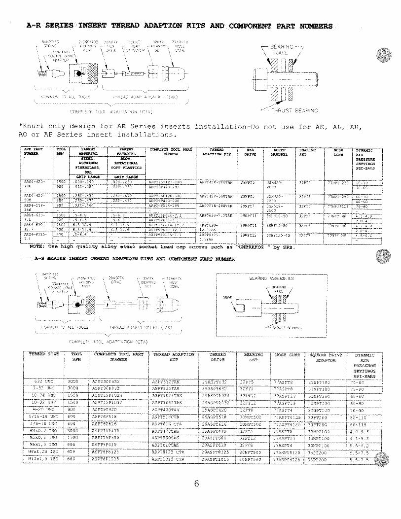
A-T SERIES AND A-W SERIES INSERT THREAD ADAPTION KITS AND
‘ — ___,,i
‘1’
0 — u’
Q
E/EAF’t
ffh &ARU
THPEA A!GE3VER & EI3ASSEME-LY FDR ERV/CE
NPT477NPTMO
NPT 6
7 01038
,NPTM4
°NPII0
1NPT101
as “CNBOOA07C” 011 SPS
THREAD CHANGEOVER USING A THREAD ADAPTION KIT (TAX)
COMPONENT PART NUMBERS
1
• -Th
Li,L1;E
L
*Krr ‘O rI7. t
THREAD CTA TAXSIZE PART NO, PART NO
‘A NTE32 tI —
01
rT2 cr N
[0’4 4E4t 1A NPT4T ibK
47/011024 CIA NP11j2417K
F # 3-32 ‘IPTI 032 TA NPI1 AK
a_S
‘
HEX f *5QCT.I
DRIVE CAP SCREW SET
2901 1 44 4” 3uNPT42°N°r x lCmr PTP43
9NP2 J #6—2. 3 4’ 0NP 6
°NPT3 -3s x 4” 01612sNP19 014 x 2 3cr 3NETP’4
#10—24 x 1 1/5” 3 NPlo
BEARING I NOSE CONE
01PLOaC CIA
2N1724
2NFT4
LNII10
,1 4— 0181420 CTAh1_/I—2JPT426C/’A
M NPT6IO CIA----
a 16—12 NP’f12 CIAr /36-24 154Ta
0 , —
‘ia 0S.a,— ±-
30-a’ 0161616 ITA
36—24 181624 ITA
2901015
#10—032 x 1 1/2”145 x O0rorn
1/4-20 x 0N$42 AK
NPT42 1/16
NPT61 TAN
NO IAN
NI 4 r%
N21a125 316
NP24
1/4—20 x 1
3&NPTM5
2°NPTa
29NPT1
2-C:P16
‘167P3 6
2918112
3NP z53CNPP20
7’NPTM5
ECIsIS CIA
049 x 35cr5/1 6—10 >, 3 3/4”5!1624 x 1 3/4”
1EET2i3 2Z1’2—2D :61020 CIA
77NPT250
7NPT25C
2. aN PC -
x 45:-n
31’/PTM6
0NP312o
NP3125
ONPIM8
NIT
75se hach
‘7NPTM6
7’NPT31257C01813127.
NIT
3’0—24 s: 1 3’4”
z 4:-arc
01CC AVA lANCE
3 N6T375
770161018
7NPT375
1/2—1: x 2”
04 2 51
- PIfO
a11c stce socket hea3. oar screws scaN
I NPT3757 N PTM 1 0
7NPT500
320161571 C72PT500
330181521 i tINPTO412
I
- -S — K100—
‘- 0r •E - ‘Er
“ -Sd” 0 S1
NI
0 0)
N,
CO
:30
03 NC NI
SC 0
U j4
CS,
N)
N, -3
CS
I0N
I0
NI3
0O
C>
flC
SO
,IC
NC
WC
OO
SO
O3)C
—C
I)SO
—15
)0
ISOCC
15)
CC0
I
30
00
COV
C)
14
a •C
C5)
55)
5—
SOC
))SO
0)0)0
0S
Ir
Cy
f0
C0
00
5555
00
00
C0
0
o—
15)
15)
CCI
0CI
)C
C00
3050
0’ :0
:0:0
O0
00
50
)C
C3)
C)C
3)
00111511
01
10
1111
3030C
-ls-
l3
03
00
3030
SOSO
SIC
—55
50—
50
C110510)
NO
N01
5CC
US
O)
C)5
r530Ø
CI
115
55C
fl
00
so
o3)
OS
351
3050
C5
N5115
ISfi
535
CI
CI
NC
SN
SN
)55355
55C
C)
5__f
C)
53,
3’14
3)3)
COSO
3,
II11
“11
3551
ftC01
;iSC
I
S’S
‘S
7
57 5
5>
N
N
SO
Cf
rt a 11 IN
C1)
555
SN
555C
I)55
CCC
555CI
CS3)
NI
3)01
NI
151
CCC
C)
UIC
USC
C)
C131C
1CC
151
“51
5)0
3030
3If
)30
33
00
)C
)5)
C0
1IC
CC
O45
0—
NX
C-51
C-
35
10
0N
5105
51
17
)S
CS
N)
(S033)03301551
CCC5
1C
0C
355
)S
)c3
55
XCS
C)SI
’S
0
HH F—1
l-C
)Q C)C
nHC
H-
C),
(D(D
CO
CK
) H-
H-
cQ
CO CD
H,
MO
rM
H C) CO ctC
f)
H-’
MF0
H
rtC
aH C)
HC
)),
CO
CK
) CD H CO H C) CO (3)
H’
H’
PC C-’
0 7 0 C) 0 rt CO CD K-b 0 H
N5S
i I ‘1
-j
1-4 N 55
9
C-
KS)
0
:: :-
E;ji;iI
CS
S-
CO15
53
CC
SN
CS
5ftC
C)
53
930
951
905
SCSC
(XC
‘3
;SC
;1
530
05C
KC
S3
C
N,
0)3
15
1541 H
X 7 (N
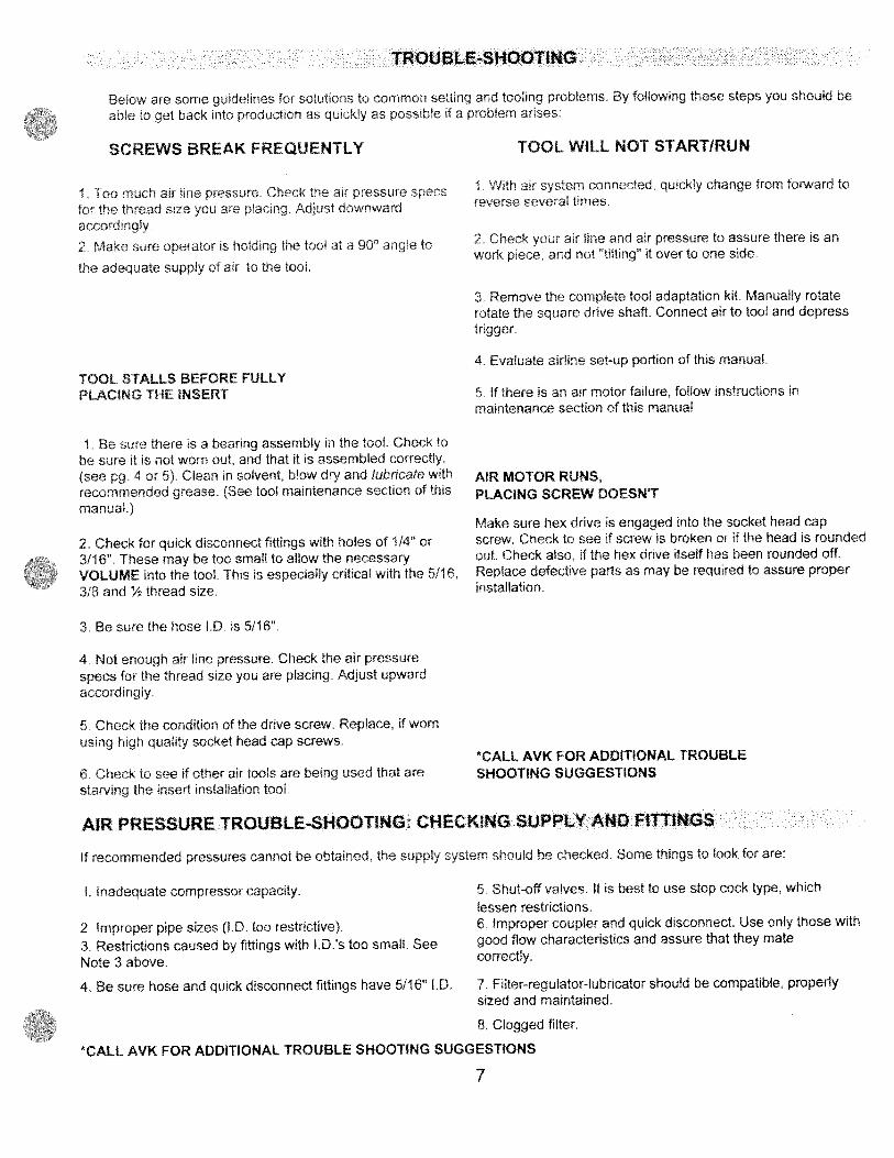
TROUBLE-SHOOTING
Below are some guidelines for solutions to common setting and tooling problems By following these steps you should beable to get back into production as quickly as possible if a problem arises:
SCREWS BREAK FREQUENTLY
1 Too much air line pressure. Check the air pressure specsfo the thread size you are placing Adjust downwardaccordingly.
2. Make sure operator is holding the tool at a 90° angle to
the adequate supply of air to the tool.
TOOL WILL NOT STARTIRUN
1 With air system connected, quickly change from forward toreverse several times.
2 Check your air line and air pressure to assure there is anwork piece., and not tilting” it over to one side.
3. Remove the complete tool adaptation kit. Manually rotaterotate the square drive shaft. Connect air to tool and depresstrigger
4 Evaluate airline set-up portion of this manual.
TOOL STALLS BEFORE FULLYPLACING THE INSERT
1 Be sure there is a bearing assembly in the tool. Check tobe sure it is not worn out, and that it is assembled correctly.(see pg. 4 or 5) Clean in solvent, blow dry and lubricate withrecommended grease. (See tool maintenance section of thismanual.)
2. Check for quick disconnect fittings with holes of 1/4” or3/16”. These may be too small to allow the necessaryVOLUME into the tool This is especially critical with the 5/16,3/8 and % thread size.
3 Be sure the hose ID. is 5/16”.
4 Not enough air line pressure. Check the air pressurespecs for the thread size you are placing. Adjust upwardaccordingly
5 Check the condition of the drive screw. Replace, if wornusing high quality socket head cap screws.
6. Check to see if other air tools are being used that arestarving the insert installation tool
5 If there is an air motor failure, follow instructions inmaintenance section of this manual
AIR MOTOR RUNS,PLACING SCREW DOESN’T
Make sure hex drive is engaged into the socket head capscrew Check to see if screw is broken or if the head is roundedout. Check also, if the hex drive itself has been rounded offReplace defective parts as may be required to assure properinstallation.
*CALL AVK FOR ADDITIONAL TROUBLESHOOTING SUGGESTIONS
AIR PRESSURE TROUBLE-SHOOTING: CHECKING SUPPLY AND FITTINGS
If recommended pressures cannot be obtained, the supply system should be checked. Some things to look for are:
I. Inadequate compressor capacity 5 Shut-off valves. It is best to use stop cock type, which
lessen restrictions.6 Improper coupler and quick disconnect. Use only those withgood flow characteristics and assure that they matecorrectly.
4. Be sure hose and quick disconnect fittings have 5/16” ID. 7. Filter-regulator-lubricator should be compatible, properlysized and maintained.
8. Clogged filter.
*CALL AVK FOR ADDITIONAL TROUBLE SHOOTING SUGGESTIONS
2. Improper pipe sizes (I.D. too restrictive).
3. Restrictions caused by fittings with ID’s too small. SeeNote 3 above.
7

THRUST BEARING
TOOL MAINTENANCE
It is essential that the thrust bearing be lubricated sith Lubtipiate* 93OA or equtsalent. The thrust bearing and mandrel(socket head cap screws — see pages 4 & 51 are located in the nose cone ot the tool I uhrtcato as needed, hearingshould not run dry. For further detail’ ee etion enrirled Thread change-oser and Di’a”emblv for service (Page’ 9 121.
Remove the nose cone & proceed as followc:
Remose thebearing andsocket head
tip cress 3 K i il’) 3
Replace sres.ssorn T se onis highqualits gradeSee pgs4& trtcngh
*LuhripIate i manufactured by I i’ke Bros. Refining Co., Lubriplae DisNon. I9 Lockss d Si \eoark. N rio. Ca 97i 599t5t for
a Distributor near you.
DISASSEMBLY FOR AIR MOTOR SERVICE
If a problem develops with the air motor,sirnply disassemble it as shon below and either send the air motor to an ARO service facilityor obtain parts from them for repair.
ARO SERVICE FACILITIES
To send a tool motor for repair or to obtain parts, call the appropriate number heloss sou aill b relured .0 the nearest ers ice
facility.
(888) 7827824
Separate thebearing ft ni thera tilt a,
Rea’emble
ii
( H hrad)
dOe
8
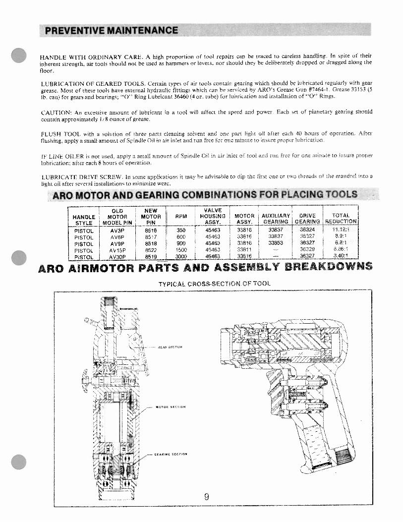
PREVENTIVE MAINTENANCE
HANDLE WITH ORDINARY CARE. A high proportion of tool repairs can be traced to careless handling. In spite of their
inherent strength, air tools should not be used as hammers or levers, nor should they be deliberately dropped or dragged along the
floor.
LUBRICATION OF GEARED TOOLS. Certain types of air tools contain gearing which should be lubricated regularly with geargrease. Most of these tools have external hydraulic fittings which can be serviced b ARO’s Grease Gun #7464 1 Grease 33153 (5lb. can> for gears and bearings; “0” Ring I ubricant 36460(4oz tube) for lubrication nd installation of “0” Rings.
CAUTION: An excessi’e amount of lubricant in a tool will affect the speed and power Each set of planetary gearing shouldcontain approximately 1/8 ounce of grease.
FLUSH TOOL with a solution of three parts cleaning sol’ent and one part light oil after each 40 hours operatiop At’erflushing, apply a small amount of Spindle Oil m ar inlet and run free for ore minrre to insure prore ibrira?i”n.
IF L1NF OILER is not used. appi a smaff amount of spndle 0° in air iliet o .oi and run cc or ne n,o:it :ure pronerlubrication; after each 8 hours of operation.
LUBRICATE DRIVE SCREW, In some appli ations it may be advisable to din the first one or two breads o ie mandrel nto alight oil after several installations to minimize wear
ARO MOTOR AND GEARING COMBINATIONS FOR PLACING TOOLS
ARC MRMOTOR PARTS AND ASSEMBLY BREAKDOWNS
TYPICAL CROSS SECI1ON OF TOOL
OLD NEW VALVEHANDLE MOTOR MOTOR RPM HOUSING MOTOR AUXILIARV DRIVE TOTAL
STYLE
PISTOL AV6P 8517 600 45463 33816 33837 36327 89:1
PISTOL AV9P 8518 900 45463 33816 33853 38327 68:1
PISTOL AV15P 8522 1500 45463 33811 — 36329 6 86:1
PISTOL AV3OP I 8519 3000 45463 33816 36327 I .340:1
k
•. 4s
GEAItI$il SECflO’
9

DISASSEMBLYa Rem’e r’nd!e and moi-ei trom Ri-c Gear.b. In remoc Gcar to’n Srtr.ii-, !ernoc Bearrr,
Spacer and Shatt.REASSEMBLY
NO1L Pack bearingc and lubricate gears ohraLls with33153 grease or equra1ent upon assembls Gearingassembly should contarn approx 1 8 o grea e
ATH Sr’oer 369i) ‘F (3369 and Gears toSprndle and secure srth Shas, argning notch inShait rth Spacer. \OYE. ShaIi (36i6) containrlteeq (15) loose eed1e Bearings (3345sj per shaft.
h. Asembk Spacer (37676), sshere applicable, andBearings to Spmdle and assemble to Ring Gear.
33436 SHt2t
36324 GEARiNG ASS Y
55€
10
[32325 BEARING
36327 GEARiNG ASSY34.
33686 SHAFT(2)UDESLcOS€NEEDLL REARINGS
PER SCFTREPLACE WITH 3365€ K T
—32325 BEARRG
-
33436 SHAF—121
36329 GEARiNG ASSY
626
GEARING SECTIONDRIVE GEARING
32325 BEARiNG—
36325 RiNG GEAR —s
36326 SPINDLE -
32325 BEARING
T
6946
33693 SACER—
34C GEAR 2—---—---—
32325 BEARiNG
36325 RiNG GEAR
—
15 (“
- 37676 SCER
3369 5ACER—3€74 SP4DLE-
30899 GEAR (2(2 TEETK
36325 RiNG GEAR —.
36330 SPINDLE —
33693 SP4CER—
33438 GEAR t2i
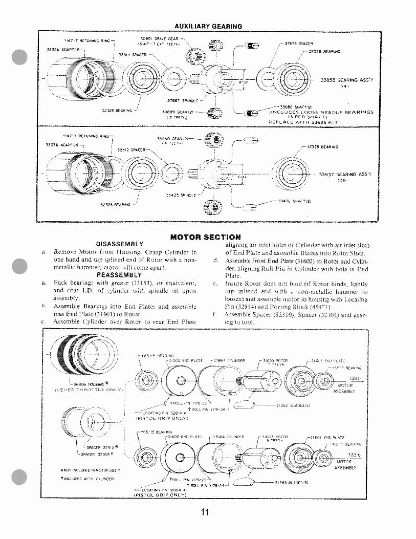
DISASSEMBLYa Remose Motor from Housing. Grasp C1inder in
one hand and tap splined end of Rotor with a nonmetallic hammer; motor w II come apart
REASSEMBLYa Pack bearings with grease (33153). or equia1ent,
and coat LD. of clinder with srindk od uponassembly
b. Assemble Beatings into EnI Plates and assemblerear End Plate (31601) Lc’ RotorAssemble (ylinder over Rrtor to rear End Plate
aligning air inlet holes of Cylinder with air inlet slotsof End Plate and assembi Bladc into R to Slots
d. Assemble front End Plate (31602) to Rotor ard Cylinder, aligning Roll Pt r C linder with 3cle in EndPlate
e, Insure Rotor uoe not bind i I Rotor bir-d lightlytap cned end wiih a non metailk hammer toloosen) and ssernhic moto to hou’in th LocatingPin (328141 and t’orrt Bick i54i
i Assemble Sna-et 321t-,, Spacer 132305) and gearing to tool
AUXILIARY GEARING
323-25 RNG
2 tE
33853 G€ARlG ASSY34
3090’ DE SEAR— -- 37476 SPACER
I477 R(’AINING RING— Ex• E[—
— 32325 SEARNG32326 AGAPTEP—3734 SPACFR
—33434 SA2i32325 8EANG ..—------ -.-——
—
fl47-7 PETANiNG RING—33DR?1—.---_.3
,——
—-3-2325 BEARING
_-——33686 SHAT2NCLjDES LOOSE NEEDLE ARINGS
15 ER SHAFT1REPLACE WiTH 33686 kIT
33837 GEARING ASSY556
MOTOR SECflOl
36606 4DuSING *
-- PT3i-
CCCj ar 3I54
i’i/__
- DATNGP’ 84 ,
IPISTC L (,RIP NLY
*NO NCLEO N MCTOR ASS
NCLD€D WFH CYLINDER RflLL PIN YI’62C
-——LOCAT1NGPN 32814 *
(PISTOL GRIP ONLYi
4EC- N
ASSEM8LY
-- 31363 9ADE3 51
11

DISASSEMBLY
HEAD SECTION M3032
o S r 4546°scrc v22 56 C a rg od 45$6S
G aca ‘J a .. d. 43S0 0 ‘88C cr4 c. ic ce tceasa cy ca ast’ -g 4546C
a <er ae rea..-•: g 4768 e sa’ea—s 42911
mjfr 454a
REASSEMBLY
Coc.e asserr
‘7 2 ca 32:-,
gs 4465b Assa ‘c a 0 r no 3257 in a csser1 v 47880’
Lubr cte cLrger L47870 cr4 vc.e ossaro 47880A’0 29665 sp ndte o
4 AssenoIe sorrgs (4880&) o va4e csse’nb y 47880,4ssernce Dargers 47879) and c ye asserro as (47880’ cD.s4s :45465’ •ad osseroe casrrcs srr a—g faTs of 0Jsnngs t.cts a’sserrbe shrc.c 45468 o rn ,s tr screV”7a.i4
a ccer c s”cac sac, “ ‘78254ssernce “Jffer 54 cr4 sc’sa—s -C3 ‘ aroas rq
nr eo”.rg rg Y147-68
45462 HOUS43 ASS Y
C,.cCS 35967 GREAsE FL
Y222 156’C SCREW’—
Yi8.25 ROLL PN-
4546g TR!GGER
—
47319 PUNGER (2—,
325-U 0 RiNG
.S46 8JSi4NG (2—’\\
s\
Y325-3 0’ RedS \
01
4548 SHROUD’-’ /Y325’2 0 Re4G (2)J
T7/ /
I! I’/ /
29880 VALVE ASSEMBLY 2)J /Y3257 0 RedS (2)—’
*NOT NCLUDED N
45463 HCUSNG S ‘ALVES ASSY
45474 MUFFLER-/
429H SCREEN (2)—’ —
Y4’68 PETANG RtNG
REVERSIBLE
45463 .-40u3;NGSVALVESASS’Y
PARTS MARKED THUS ARE INCLUDED IN SERVICE KIT NO. 421222, SEE PAGE iO
12


z 0 -1 m

z 0 -1 m U)
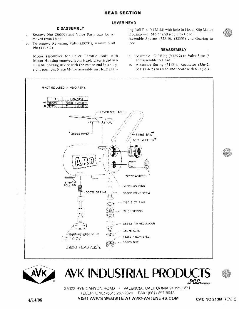
HEAD SECflON
LEVER HEAD
DISASSEMBLY
a. Remove Nut (36609) and Valve Parts may be removed from Head.
b. To remove Resersing Valve (39207). remose RollPin (Y178-7).
Motor assemblies for Lever Throttle tools: with
Motor Housing removed from Head; place Head in asuitable holding device with the motor end in an upright position. Place Motor assembly on Head align-
ing Roll Pin (Yl8-24) with hole in Head, Slip MotorHousing over Motor and secure to Head.Assemble Spacers (32310), (32305) and Gearing totool.
REASSEMBLY
a. Assemble “0” Ring (Y125-2) to Valve Stem (3and assemble to Head.
b. Assemble Spring (31131), Regulator (35642)Seal (35675) to Head and secure with Nut (366(
[ “A” LENGTH
.- 3-5/8 INCHES
AVK INDUSTRIAL PRODUCTSAi’Company
25323 RYE CANYON ROAD • VALENCIA, CALIFORNIA 91 355-1271TELEPHONE (661) 257-2329 FAX. (661) 257-8043
VISIT AVK’S WEBSITE AT AVKFASTENERSCOM
*NOT INCLUDED IN HEAD ASSY
** 36778 7 INCHES I
LEVER (SEE TABLEt
*36992 RIVET—/ *
— 32863 BAIL
-40191 MUFFLER*
—
32377 ADAPTER—’
36602 VALVE STEM
39209 HOUSING
30032 SPRING
Y125-2 0 RING
31(31 SPRING
392T—REVERSE VALVE
_—-- 35642 A R REGULATOR
35675 SEAL
39210 HEAD ASSY
73262 NYLON BALL
36609 NUT
4/14/08 CAT. NO 213M REV C