thoracolumbar solutions polaris - zimmer biomet„¢ 5.5 spinal system—surgical technique guide 3...
TRANSCRIPT

Surgical Technique Guide
Polaris™ 5.5 Spinal System
Thoracolumbar Solutions

2 Polaris™ 5.5 Spinal System—Surgical Technique Guide

Polaris™ 5.5 Spinal System—Surgical Technique Guide 3
Zimmer Biomet Spine does not practice medicine. This technique was developed in conjunction
with health care professionals. This document is intended for surgeons and is not intended for
laypersons. Each surgeon should exercise his or her own independent judgment in the diagnosis
and treatment of an individual patient, and this information does not purport to replace the
comprehensive training surgeons have received. As with all surgical procedures, the technique
used in each case will depend on the surgeon’s medical judgment as the best treatment for each
patient. Results will vary based on health, weight, activity and other variables. Not all patients are
candidates for this product and/or procedure.
TABLE OF CONTENTS
Polaris 5.5 Spinal System Overview 4
Surgical Approach and Preparation 6
Pedicle Preparation 7
Screw Selection and Insertion 9
Screw Height Adjustment 11
Rod Application 11
Helical Flange® Plug Application 12
Final Locking 12
Surgical Options
Reduction Options 14
Distraction and Compression 16
Cross Connector Application 17
Lateral Connectors 18
Closure 19
Implant Removal 19
Implants 20
Instrumentation 22
Recommended Ordering Guide 25
Kit Contents 26
Important Information on the Polaris 5.5 Spinal System 30

4 Polaris™ 5.5 Spinal System—Surgical Technique Guide
POLARIS 5.5 SPINAL SYSTEM OVERVIEW
We’ve Got the Lock on Pedicle Screw Technology
• Incorporates Helical Flange® Technology that minimizes seat splay and cross threading
• Load sharing, top loading, low profile system
The Polaris 5.5 Spinal System was created to offer a streamlined lumbar fixation system that uses a superior locking mechanism.
The System incorporates Helical Flange Technology that minimizes seat-splay and cross threading. The forces are concentrated inward, thus enabling the seat and plug to create a reliable mechanical lock.
The Polaris 5.5 Spinal System is a load-sharing, top-loading, low-profile system. The seat enables secure interface with the instruments for maximal manipulation agility. The design goals were to aid the surgeon with intraoperative efficiency and effectiveness while maintaining integrity and ease.
The Polaris 5.5 Spinal System is designed to address degenerative pathologies. The trays are configured to include multi-axial screws, extended screws, precut precontoured rods, Crossbar™ cross connectors*, lateral connectors and ergonomic instrumentation for maximum tactile feedback. The Polaris System continues to advance the spinal fixation needs of the aging population by providing fixation, variability and ease of use.
* The Crossbar™ cross connector was developed by SeaSpine, Inc.

Polaris™ 5.5 Spinal System—Surgical Technique Guide 5
System Design Features and Benefits
FEATURES BENEFITS
Helical Flange Technology Starts easily
Minimizes cross threading and seat splay
Forces are concentrated inward
5.5 mm rod system Low profile
Anatomic fit
Color-coded implants Easy determination of screw sizes and instruments
Streamlined instruments Logical and ergonomic
Screwdrivers One piece, easy to use
Provide for maximal visualization
Control of screw trajectory
Minimum number of trays in operating room Only two trays necessary per case
High on head instrument interface Easy rod manipulation and excellent interface with instruments
Rod reducer Very powerful and controlled
User-friendly
Locks onto seat for easy rod reduction
Multi-axial screws Allow for 60° of angulation for optimum versatility
Friction fit seat Once the seat is in place, it remains in place for ease of rod introduction
Connection to Zimmer Biomet Spine posterior systems Easy addition to the Altius M-INI system
Extended seat multi-axial screws Allows for reducing a spondylolisthesis
Hydroxyapatite (HA) coated multi-axial screws Dual lead screw thread for faster screw placement
Balanced-start Tip geometry provides immediate engagement and minimizes toggle during insertion
Translation™ screw technology 3 mm of medial-lateral translation relative to the screw shaft
Encourages optimal screw placement
Less rod manipulation, easier rod introduction
6 Polaris™ 5.5 Spinal System—Surgical Technique Guide
SURGICAL APPROACH AND PREPARATION
STEP 1
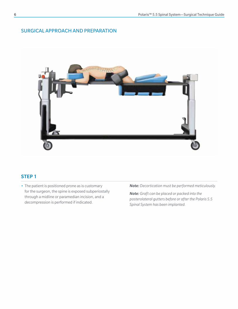
• The patient is positioned prone as is customary for the surgeon, the spine is exposed subperiostally through a midline or paramedian incision, and a decompression is performed if indicated.
Note: Decortication must be performed meticulously.
Note: Graft can be placed or packed into the posterolateral gutters before or after the Polaris 5.5 Spinal System has been implanted.

Polaris™ 5.5 Spinal System—Surgical Technique Guide 7
STEP 2
• After adequate exposure is achieved, the appropriate pedicle entry point is selected and the entrance to the pedicle is opened with an awl, burr or curette.
• The appropriate diameter reamer probe is used to prepare the pedicle using a slow circular motion, allowing the reamer probe to center itself along the longitudinal axis of the pedicle.
• Each reamer probe is marked with the major diameter of the screw with which it is to be used. The reamer probe is initially advanced to a depth of approximately 30 mm using the depth markings as a guide.
Note: Instead of a reamer probe, a pedicle probe can be used. The pedicle probe is used to create the pedicle hole by advancing the probe to a depth of approximately 30–40 mm using the depth markings as a guide.
STEP 3
• Although the screws are self-tapping, taps are available with the system and can be used to prepare the pedicle hole. Select the corresponding tap for the chosen screw diameter and advance the tap into the pedicle hole using the quick-connect handle.
PEDICLE PREPARATION
Open the entrance to the pedicle with the pedicle awl.
Prepare the pedicle hole with the reamer probe. Prepare the pedicle hole with the chosen tap.
8 Polaris™ 5.5 Spinal System—Surgical Technique Guide
STEP 4
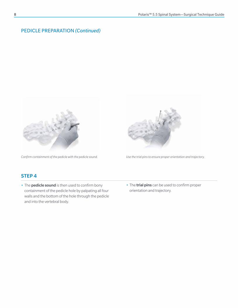
• The pedicle sound is then used to confirm bony containment of the pedicle hole by palpating all four walls and the bottom of the hole through the pedicle and into the vertebral body.
Use the trial pins to ensure proper orientation and trajectory.Confirm containment of the pedicle with the pedicle sound.
• The trial pins can be used to confirm proper orientation and trajectory.
PEDICLE PREPARATION (Continued)

Polaris™ 5.5 Spinal System—Surgical Technique Guide 9
SCREW SELECTION AND INSERTION
Select the appropriate screw size. Push the button located at the top of the knurled T, and load the screw onto multi-axial screwdriver.
STEP 6
• Hold the screw by the screw shaft and load the screw onto the tip of the multi-axial screwdriver.
Note: The multi-axial screws may be loaded freehand or while seated within the surgical tray.
• Ensure that the male pentalobe at the distal tip of the multi-axial driver is fully seated within the female pentalobe located at the top of the screw shaft.
• Push the button located at the knurled T.
• Next, turn the knurled T in a clockwise direction to thread the outer shaft into the seat. Upon fully loading, the button on the T will release.
• Confirm that the screw is straight and secure in the driver.
STEP 5
• Attach the multi-axial screwdriver to the quick connect handle by pulling back on the plunger at the base of the quick connect mechanism, inserting the shaft and releasing the plunger to lock the shaft in place.
Note: Self-tapping screws are available in several diameters and lengths.
Note: The appropriate screw length is determined using the depth markings on the pedicle probe or reamer probe.

10 Polaris™ 5.5 Spinal System—Surgical Technique Guide
Turn the knurled T counterclockwise to release from the screw. Once inserted to desired depth, push the button in.
SCREW SELECTION AND INSERTION (Continued)
Insert the screw into the pedicle.
STEP 8
• The driver is disengaged from the screw by pushing the button on the knurled T in and rotating the knurled T in a counterclockwise direction and then lifting the driver from the screw.
STEP 7
• The screw is advanced into the pedicle to the desired depth.
• During insertion, guide the driver by holding the blue sleeve on the shaft of the instrument.

Polaris™ 5.5 Spinal System—Surgical Technique Guide 11
ROD APPLICATION
Select appropriate length rod. Set the dial on the rod bender to achieve the desired curvature.
Measure length of the rod using the rod template.
Insert rod using the rod holder.
STEP 9
• The dorsal height adjuster may be used to adjust the multi-axial screw height prior to rod placement.
• Seat the male pentalobe of the dorsal height adjuster into the female pentalobe located at the top of the screw shaft.
• Turn the adjuster for minor manipulation of the screw height.
Use the dorsal height adjustor to adjust the screws.
SCREW HEIGHT ADJUSTMENT
STEP 10
• Once all screws have been inserted, the appropriate length rod should be chosen according to the construct.
• The rod template may be used to aid in rod selection. The rod should project at least 2.0 mm beyond the screw seats at the end of the construct.
• Be sure to account for large curves and distractions when choosing rod length. If necessary, the selected rod may be contoured with the rod bender.

12 Polaris™ 5.5 Spinal System—Surgical Technique Guide
FINAL LOCKING
STEP 12
After provisional tightening, proper implant placement should be confirmed with radiographs. The plugs are then tightened with either the torque-indicating wrench or the torque-limiting wrench in combination with the torque stabilizer.
• Insert the chosen torquing device through the center of the torque stabilizer. Position the tip of the torque wrench into the plug. Seat the distal end of the torque stabilizer over the screw seat and confirm that the stabilizer fits firmly on the rod. The rod will be positioned within the slots of the stabilizer.
Load plug onto the double end plug starter.
STEP 11
• When all screws have been inserted and the rods have been placed in the screw seats, the construct is then secured using Helical Flange plugs.
• One plug is firmly pressed onto each end of the double end plug starter. All plugs should be placed and then provisionally tightened.
• If necessary, the plug starter may be used in combination with the rod persuader, reduction fork or rod pusher.
Note: Reference pages 14 and 15 for reduction options.
Insert plug.
HELICAL FLANGE PLUG APPLICATION

Polaris™ 5.5 Spinal System—Surgical Technique Guide 13
Arrows of the torque-indicating wrench align at 0, signifying the start position. When the torque level is achieved, the arrow will align at 110 in-lbs. THERE IS NO AUDIBLE CLICK.
Turn the torque-limiting wrench clockwise until an audible click is heard at 110 in-lbs of torque.
Final Tightening — Torque-indicating Handle
• The torque-indicating wrench is turned in a clockwise direction while the torque stabilizer is held with resistive force in a counterclockwise direction. Two etched arrows indicate when the appropriate torque is obtained. The first set of arrows lines up showing the start position at zero. Upon reaching the intended final torque, two arrows will line up at 110 in-lbs.
Note: THERE IS NO AUDIBLE CLICK with the torque-indicating wrench. Over-torquing with the torque-indicating wrench (turning beyond the point where the arrows line up) may damage the wrench. Always ensure the wrench indicates 0 in-lbs. of torque prior to use.
Final Tightening — Torque-limiting Handle
• The torque-limiting handle attaches to the plug driver. The torque-limiting wrench is turned in a clockwise direction while the torque stabilizer is held with resistive force in a counterclockwise direction. The torque-limiting wrench should be turned until an audible click is heard, applying 110 in-lbs of torque.
Note: Use the chosen torque instrument in combination with the torque stabilizer.

14 Polaris™ 5.5 Spinal System—Surgical Technique Guide
The persuader may be used to fully seat the rod in the screw seat.
SURGICAL OPTIONSReduction Options
STEP 12 (Continued)
• When using the rod persuader, place the persuader over the top of the screw seat. The internal stop of the persuader will ensure that the instrument is in the correct position on the seat to facilitate manipulation.
• Squeeze the handle of the rod persuader to fully seat the rod in the screw seat. The plug starter will fit through the cannulated portion of the persuader, allowing for plug application with the rod persuader in place.
• To release the persuader, press the trigger located underneath the handle. Once released, the persuader may then be removed from the screw seat.
Reduction fork
Position the reduction fork under the screw seat and tilt the instrument to persuade the rod into the screw seat.
• When using the reduction fork, position the fork section underneath screw seat. Tilt the reduction fork to persuade the rod into the screw seat.

Polaris™ 5.5 Spinal System—Surgical Technique Guide 15
Push the rod down to persuade the rod into the seat and insert the plug.
Torque stabilizer may be used to guide the plug starter.
The soft tissue retractor aids retraction of the soft tissue away from the screw seat.
• When using the rod pusher, place the distal tip onto the rod and push the rod down to persuade the rod into the screw seat.
• The torque stabilizer may be used to reposition the axis of the screw seat while simultaneously acting as a guide for the plug starter.
Note: If soft tissue is interfering with proper plug placement, the soft tissue retractor may be used to retract the soft tissue away from the screw by placing the bifid tip of the retractor under the screw seat.

16 Polaris™ 5.5 Spinal System—Surgical Technique Guide
SURGICAL OPTIONS (Continued)Distraction and Compression
Provisionally tighten the plug while the compressor or distractor is in place.
• Distraction and compression can be achieved by using either the distractor or compressor. Both instruments permit intraoperative application of linear distraction or compression at any level.
• The distal tips of the distractor or compressor are placed on the rod, and the desired degree of distraction or compression is applied.
• The distraction or compression device will maintain the position of the vertebra until the plug is provisionally tightened with the plug starter connected to the chosen quick connect handle.

Polaris™ 5.5 Spinal System—Surgical Technique Guide 17
• Apply the cross connector to the rods and tighten the screws with the cross connector torque wrench until an audible click is heard, applying 40 in-lbs of torque to the set screws (tighten the outer set screws, then the central set screw).
Select the appropriate sized cross connector. Torque the set screws on the cross connector. Torque until an audible click is heard to apply 40 in-lbs.
Cross Connector Application
• In the event that additional torsional stability is required, a cross connector can be used. The cross connector should be applied after the construct has been assembled and the plugs have been tightened.
18 Polaris™ 5.5 Spinal System—Surgical Technique Guide
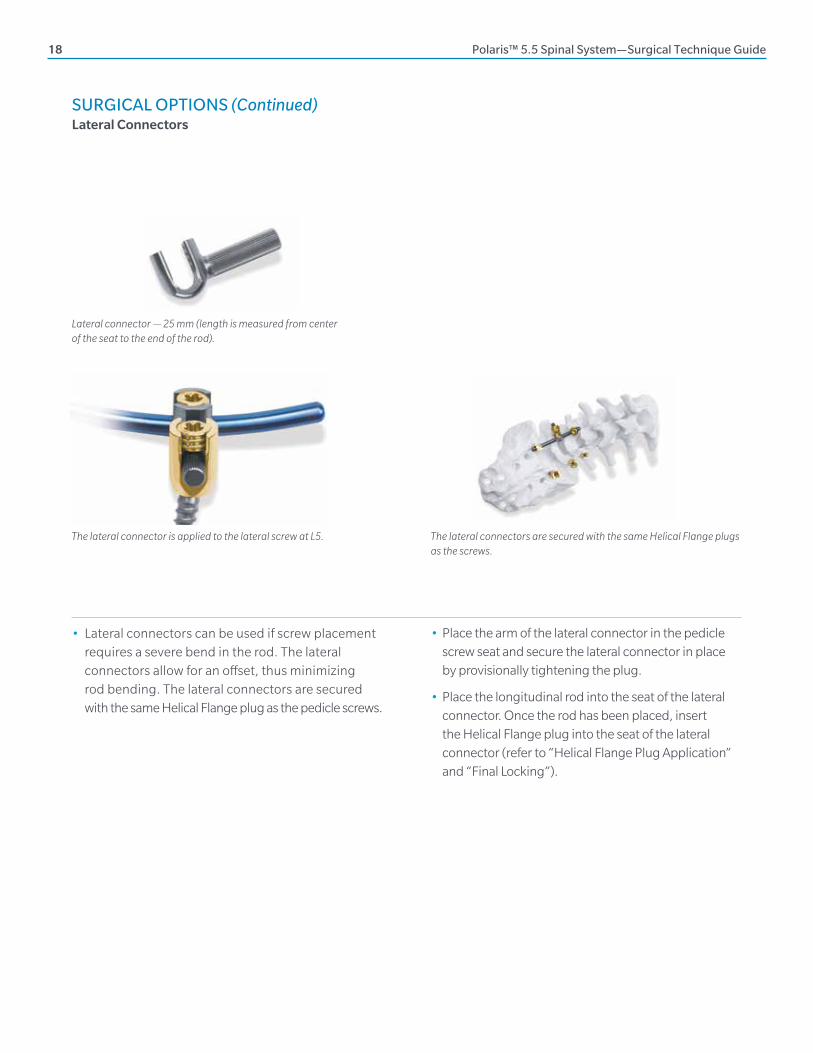
• Lateral connectors can be used if screw placement requires a severe bend in the rod. The lateral connectors allow for an offset, thus minimizing rod bending. The lateral connectors are secured with the same Helical Flange plug as the pedicle screws.
• Place the arm of the lateral connector in the pedicle screw seat and secure the lateral connector in place by provisionally tightening the plug.
• Place the longitudinal rod into the seat of the lateral connector. Once the rod has been placed, insert the Helical Flange plug into the seat of the lateral connector (refer to “Helical Flange Plug Application” and “Final Locking”).
Lateral connector — 25 mm (length is measured from center of the seat to the end of the rod).
The lateral connector is applied to the lateral screw at L5. The lateral connectors are secured with the same Helical Flange plugs as the screws.
SURGICAL OPTIONS (Continued)Lateral Connectors

Polaris™ 5.5 Spinal System—Surgical Technique Guide 19
CLOSURE IMPLANT REMOVAL
Use the multi-axial screwdriver to remove the screw.
• The multi-axial screwdriver is used to remove the multi-axial screws by seating the male pentalobe end into the female pentalobe at the top of the screw shaft.
• Slide the outer sleeve down and turn the large knurled T clockwise to lock into the screw seat.
• Once the driver is tightened, the screw may be backed out of the pedicle.
• Removal of the Polaris 5.5 Spinal System is performed by reversing the order of the implant procedure. The quick connect fixed T-handle attached to the plug driver in combination with the torque stabilizer must be used first to remove the plugs.
Note: When removing previously torqued plugs, turn the fixed T-handle in a slight clockwise direction before turning counterclockwise. Continue with this back-and-forth motion until the plug loosens.
• After implantation of the Polaris 5.5 Spinal System is complete, wound closure is performed according to the standard protocol for the surgeon.

20 Polaris™ 5.5 Spinal System—Surgical Technique Guide
IMPLANTS
Helical Flange Plug PART NUMBER
2000-1005
Lateral Connector, 25 mm PART NUMBER
2000-1020
Multi-axial Screws
Multi-axial Screws are available in 4.75-, 5.5-, 6.5-, 7.5- and 8.5-mm diameters in 30–55-mm lengths.
Multi-axial Reduction Screws
Multi-axial Reduction Screws are available in 5.5-, 6.5- and 7.5-mm diameter in 30–55-mm lengths.
Translation Screws
Translation Screws are available in 4.75-, 5.5-, 6.5- and 7.5-mm diameters in 30–55-mm lengths.
Translation Iliac Screws
Translation Iliac Screws are available in 6.5-, 7.5- and 8.5-mm diameters in 35–100-mm lengths.
HA Coated Screws
Hydroxyapatite (HA) Coated Screws are available in 5.5-, 6.5-, 7.5- and 8.5-mm diameters in a variety of lengths.

Polaris™ 5.5 Spinal System—Surgical Technique Guide 21
Pre-cut, Contoured Rods PART NUMBER
Ti Alloy 30–100 mm, increments of 5 mm See pages 27, 28
Telescoping and Angulating Crossbar Cross Connectors PART NUMBER
Ranging in length from 16–75 mm See pages 27, 28

22 Polaris™ 5.5 Spinal System—Surgical Technique Guide
Fixed T-handle PART NUMBER
95697
Ratcheting Teardrop Handle PART NUMBER
2000-6481
Awl Shaft PART NUMBER
94505
Thoracic Pedicle Probe PART NUMBER
14-500100
Straight Pedicle Probe PART NUMBER
14-500101
Curved Pedicle Probe PART NUMBER
14-500102
Fixed Handle–Straight PART NUMBER
94699
Ratchet Handle–Straight PART NUMBER
124799
Ratchet T-handle PART NUMBER
124797
Fixed Teardrop Handle PART NUMBER
2000-9006
INSTRUMENTATION
Reamer Probe PART NUMBER
4.75 mm 2000-9091
5.5 mm 2000-9092
6.5 mm 2000-9093
7.5 mm 2000-9094
Tap PART NUMBER
4.75 mm 2000-9023
5.5 mm 2000-9024
6.5 mm 2000-9025
7.5 mm 2000-9026
8.6 mm 2000-9027

Polaris™ 5.5 Spinal System—Surgical Technique Guide 23
Multi-axial Screwdriver PART NUMBER
Multi-axial Screw Inserter Universal 14-500185
Translation Screwdriver 14-500070
Dorsal Height Adjuster PART NUMBER
2000-9072
Rod Template PART NUMBER
94612
Straight Rod Pusher PART NUMBER
2000-9059
Trial Pins PART NUMBER
9 cm 4077
11 cm 4072
Rod Holder PART NUMBER
94613
Rod Persuader PART NUMBER
Parallel 2000-9055
Perpendicular 14-500198
Rod Bender PART NUMBER
2000-9044
Plug Driver PART NUMBER
2000-9061
Double End Plug Starter PART NUMBER
2000-9060
Reduction Fork PART NUMBER
2000-9054
Stiff Pedicle Sound PART NUMBER
4010
Flexible Pedicle Sound PART NUMBER
2000-9015
Soft Tissue Retractor PART NUMBER
94614

24 Polaris™ 5.5 Spinal System—Surgical Technique Guide
Compressor PART NUMBER
94686
Distractor PART NUMBER
94687
Cross Connector Torque Wrench PART NUMBER
94624
Torque-limiting Wrench PART NUMBER
94522
Torque-indicating Wrench PART NUMBER
2000-9082
Torque Stabilizer PART NUMBER
2000-9075
Reduction Screw Break-off Stabilizer PART NUMBER
2000-9019
Reduction Screw Break-off Plier PART NUMBER
2000-9074
Short Rocket Threaded Reducer PART NUMBER
14-500200
Offset T-handle PART NUMBER
14-500201
T-handle PART NUMBER
14-500203
QC Adaptor PART NUMBER
14-500202
INSTRUMENTATION (Continued)
Polaris™ 5.5 Spinal System—Surgical Technique Guide 25
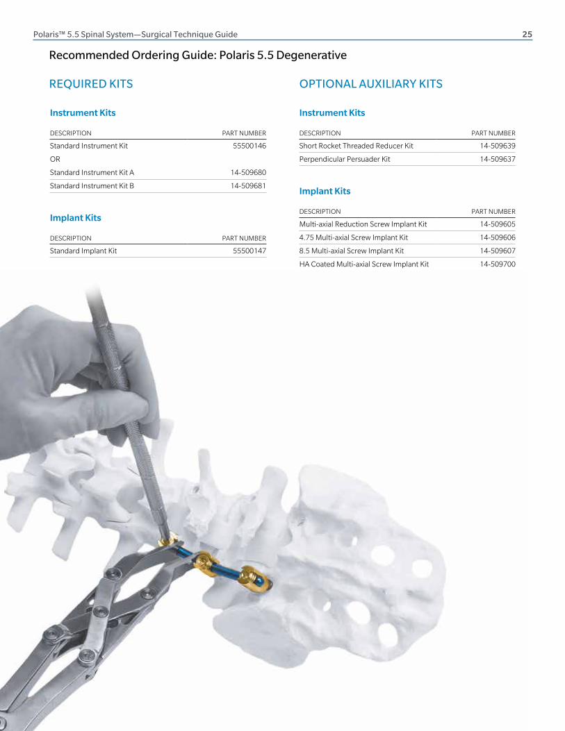
REQUIRED KITS
Recommended Ordering Guide: Polaris 5.5 Degenerative
DESCRIPTION PART NUMBER
Standard Instrument Kit 55500146
OR
Standard Instrument Kit A 14-509680
Standard Instrument Kit B 14-509681
Instrument Kits
DESCRIPTION PART NUMBER
Standard Implant Kit 55500147
Implant Kits
OPTIONAL AUXILIARY KITS
DESCRIPTION PART NUMBER
Short Rocket Threaded Reducer Kit 14-509639
Perpendicular Persuader Kit 14-509637
Instrument Kits
DESCRIPTION PART NUMBER
Multi-axial Reduction Screw Implant Kit 14-509605
4.75 Multi-axial Screw Implant Kit 14-509606
8.5 Multi-axial Screw Implant Kit 14-509607
HA Coated Multi-axial Screw Implant Kit 14-509700
Iliac Screw Implant Kit 14-509635
Translation Screw Standard Implant Kit 14-509669
Translation 4.75 Screw Implant Kit 14-509682
Translation Iliac Screw Implant Kit 14-509668
Implant Kits

26 Polaris™ 5.5 Spinal System—Surgical Technique Guide
KIT CONTENTS
DESCRIPTION QTY PART NUMBER
Plug Driver 2 2000-9061
Multi-axial Screw Inserter 2 14-500185
Torque Stabilizer 1 2000-9075
Torque-limiting Wrench,110 in-lbs 1 94522
Awl Shaft 1 94505
Thoracic Pedicle Probe 1 14-500100
Straight Pedicle Probe 1 14-500101
Curved Pedicle Probe 1 14-500102
Flexible Sound 1 2000-9015
Stiff Sound 1 4010
9.0 cm Trial Pin 4 4077
11 cm Trial Pin 4 4072
4.75 mm Tap 1 2000-9023
5.5 mm Tap 1 2000-9024
6.5 mm Tap 1 2000-9025
7.5 mm Tap 1 2000-9026
8.5 mm Tap 1 2000-9027
Reduction Fork 1 2000-9054
Rod Persuader 1 2000-9055
Straight Rod Pusher 1 2000-9059
Double End Plug Starter 2 2000-9060
Dorsal Height Adjuster 1 2000-9072
Reduction Screw Break-off Plier 1 2000-9074
4.75 mm Reamer Probe 1 2000-9091
5.5 mm Reamer Probe 1 2000-9092
6.5 mm Reamer Probe 1 2000-9093
7.5 mm Reamer Probe 1 2000-9094
Ratchet T-handle 1 124797
Ratchet Handle–Straight 1 124799
Rod template 1 94612
Rod Holder 1 94613
Soft Tissue Retractor 1 94614
Cross Connector Torque Wrench 1 94624
Compressor 1 94686
Distractor 1 94687
Rod Bender 1 2000-9044
Fixed T-handle 1 94697
Fixed Handle–Straight 1 94699
Teardrop Handle–Fixed 1 2000-9006
Reduction Screw Break-off stabilizer 1 2000-9019
Standard Instrument Kit 55500146
Standard Instrument Kit A 14-509680
DESCRIPTION QTY PART NUMBER
Plug Driver 2 2000-9061
Multi-axial Screw Inserter 2 14-500185
Rod Rocker, Extended Throw 1 14-500197
Torque Stabilizer 1 14-500018
Torque-limiting Wrench Handle 2 94522
Awl Shaft 1 94505
Thoracic Pedicle Probe 1 14-500001
Straight Pedicle Probe 1 14-500002
Curved Pedicle Probe 1 14-500003
Firm Pedicle Sound 1 14-500007
Flexible Pedicle Sound 1 2000-9015
4.75 mm Tap 1 2000-9023
5.5 mm Tap 1 2000-9024
6.5 mm Tap 1 2000-9025
7.5 mm Tap 1 2000-9026
8.5 mm Tap 1 2000-9027
Screw Head Positioner 1 14-500072
Plug Starter 2 14-500170
Dorsal Height Adjuster 1 14-501680
Ratchet T-handle 1 124797
Ratchet Handle–Straight 1 124799
Rod Holder 1 94613
Cross Connector Torque Wrench 1 94624
Teardrop Handle–Fixed 1 2000-6481
Standard Instrument Kit B 14-509681
DESCRIPTION QTY PART NUMBER
Reduction Screw Break-off Plier 1 14-500009
Perpendicular Rod Persuader 1 14-500198
Rod Bender 1 2000-9044
Parallel Compressor 1 94686
Parallel Distractor 1 94687
Short Rocket Threaded Persuader Kit 14-509639
DESCRIPTION QTY PART NUMBER
Short Threaded Rod Persuader 6 14-500200
T-handle Persuader 2 14-500201
QC Adaptor 1 14-500202
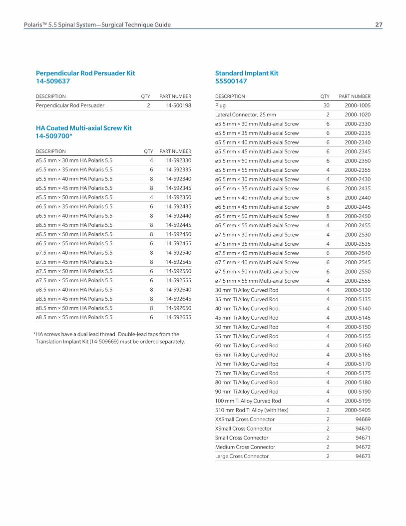
Polaris™ 5.5 Spinal System—Surgical Technique Guide 27
DESCRIPTION QTY PART NUMBER
ø5.5 mm × 30 mm HA Polaris 5.5 4 14-592330
ø5.5 mm × 35 mm HA Polaris 5.5 6 14-592335
ø5.5 mm × 40 mm HA Polaris 5.5 8 14-592340
ø5.5 mm × 45 mm HA Polaris 5.5 8 14-592345
ø5.5 mm × 50 mm HA Polaris 5.5 4 14-592350
ø6.5 mm × 35 mm HA Polaris 5.5 6 14-592435
ø6.5 mm × 40 mm HA Polaris 5.5 8 14-592440
ø6.5 mm × 45 mm HA Polaris 5.5 8 14-592445
ø6.5 mm × 50 mm HA Polaris 5.5 8 14-592450
ø6.5 mm × 55 mm HA Polaris 5.5 6 14-592455
ø7.5 mm × 40 mm HA Polaris 5.5 8 14-592540
ø7.5 mm × 45 mm HA Polaris 5.5 8 14-592545
ø7.5 mm × 50 mm HA Polaris 5.5 6 14-592550
ø7.5 mm × 55 mm HA Polaris 5.5 6 14-592555
ø8.5 mm × 40 mm HA Polaris 5.5 8 14-592640
ø8.5 mm × 45 mm HA Polaris 5.5 8 14-592645
ø8.5 mm × 50 mm HA Polaris 5.5 8 14-592650
ø8.5 mm × 55 mm HA Polaris 5.5 6 14-592655
HA Coated Multi-axial Screw Kit 14-509700*
* HA screws have a dual lead thread. Double-lead taps from the Translation Implant Kit (14-509669) must be ordered separately.
Perpendicular Rod Persuader Kit 14-509637
DESCRIPTION QTY PART NUMBER
Perpendicular Rod Persuader 2 14-500198
Standard Implant Kit 55500147
DESCRIPTION QTY PART NUMBER
Plug 30 2000-1005
Lateral Connector, 25 mm 2 2000-1020
ø5.5 mm × 30 mm Multi-axial Screw 6 2000-2330
ø5.5 mm × 35 mm Multi-axial Screw 6 2000-2335
ø5.5 mm × 40 mm Multi-axial Screw 6 2000-2340
ø5.5 mm × 45 mm Multi-axial Screw 6 2000-2345
ø5.5 mm × 50 mm Multi-axial Screw 6 2000-2350
ø5.5 mm × 55 mm Multi-axial Screw 4 2000-2355
ø6.5 mm × 30 mm Multi-axial Screw 4 2000-2430
ø6.5 mm × 35 mm Multi-axial Screw 6 2000-2435
ø6.5 mm × 40 mm Multi-axial Screw 8 2000-2440
ø6.5 mm × 45 mm Multi-axial Screw 8 2000-2445
ø6.5 mm × 50 mm Multi-axial Screw 8 2000-2450
ø6.5 mm × 55 mm Multi-axial Screw 4 2000-2455
ø7.5 mm × 30 mm Multi-axial Screw 4 2000-2530
ø7.5 mm × 35 mm Multi-axial Screw 4 2000-2535
ø7.5 mm × 40 mm Multi-axial Screw 6 2000-2540
ø7.5 mm × 40 mm Multi-axial Screw 6 2000-2545
ø7.5 mm × 50 mm Multi-axial Screw 6 2000-2550
ø7.5 mm × 55 mm Multi-axial Screw 4 2000-2555
30 mm Ti Alloy Curved Rod 4 2000-5130
35 mm Ti Alloy Curved Rod 4 2000-5135
40 mm Ti Alloy Curved Rod 4 2000-5140
45 mm Ti Alloy Curved Rod 4 2000-5145
50 mm Ti Alloy Curved Rod 4 2000-5150
55 mm Ti Alloy Curved Rod 4 2000-5155
60 mm Ti Alloy Curved Rod 4 2000-5160
65 mm Ti Alloy Curved Rod 4 2000-5165
70 mm Ti Alloy Curved Rod 4 2000-5170
75 mm Ti Alloy Curved Rod 4 2000-5175
80 mm Ti Alloy Curved Rod 4 2000-5180
90 mm Ti Alloy Curved Rod 4 000-5190
100 mm Ti Alloy Curved Rod 4 2000-5199
510 mm Rod Ti Alloy (with Hex) 2 2000-5405
XXSmall Cross Connector 2 94669
XSmall Cross Connector 2 94670
Small Cross Connector 2 94671
Medium Cross Connector 2 94672
Large Cross Connector 2 94673

28 Polaris™ 5.5 Spinal System—Surgical Technique Guide
KIT CONTENTS (Continued)
5.5 mm Translation Screw Standard Implant Kit14-509669 (Continued)
DESCRIPTION QTY PART NUMBER
ø5.5 mm × 25 mm 5.5 Translation Screw 2 14-578325
ø5.5 mm × 30 mm 5.5 Translation Screw 6 14-578330
ø5.5 mm × 35 mm 5.5 Translation Screw 8 14-578335
ø5.5 mm × 40 mm 5.5 Translation Screw 8 14-578340
ø5.5 mm × 45 mm 5.5 Translation Screw 8 14-578345
ø5.5 mm × 50 mm 5.5 Translation Screw 4 14-578350
ø5.5 mm × 55 mm 5.5 Translation Screw 2 14-578355
ø6.5 mm × 30 mm 5.5 Translation Screw 4 14-578430
ø6.5 mm × 35 mm 5.5 Translation Screw 6 14-578435
ø6.5 mm × 40 mm 5.5 Translation Screw 8 14-578440
ø6.5 mm × 45 mm 5.5 Translation Screw 8 14-578445
ø6.5 mm × 50 mm 5.5 Translation Screw 8 14-578450
ø6.5 mm × 55 mm 5.5 Translation Screw 6 14-578455
ø7.5 mm × 30 mm 5.5 Translation Screw 4 14-578530
ø7.5 mm × 35 mm 5.5 Translation Screw 6 14-578535
ø7.5 mm × 40 mm 5.5 Translation Screw 8 14-578540
ø7.5 mm × 45 mm 5.5 Translation Screw 8 14-578545
ø7.5 mm × 50 mm 5.5 Translation Screw 8 14-578550
ø7.5 mm × 55 mm 5.5 Translation Screw 6 14-578555
Plug 30 2000-1005
Lateral Connector, Open, 25 mm 2 2000-1020
30 mm Ti Alloy Curved Rod 4 2000-5130
35 mm Ti Alloy Curved Rod 4 2000-5135
40 mm Ti Alloy Curved Rod 4 2000-5140
45 mm Ti Alloy Curved Rod 4 2000-5145
50 mm Ti Alloy Curved Rod 4 2000-5150
55 mm Ti Alloy Curved Rod 4 2000-5155
60 mm Ti Alloy Curved Rod 4 2000-5160
65 mm Ti Alloy Curved Rod 4 2000-5165
70 mm Ti Alloy Curved Rod 4 2000-5170
75 mm Ti Alloy Curved Rod 4 2000-5175
80 mm Ti Alloy Curved Rod 4 2000-5180
90 mm Ti Alloy Curved Rod 4 2000-5190
100 mm Ti Alloy Curved Rod 4 2000-5199
510 mm Ti Alloy Rod with Hex 2 2000-5405
XXSmall Cross Connector 2 94669
XSmall Cross Connector 2 94670
Small Cross Connector 2 94671
Medium Cross Connector 2 94672
Large Cross Connector 2 94673
DESCRIPTION QTY PART NUMBER
ø4.75 mm × 20 mm Multi-axial Screw 12 2000-2220
ø4.75 mm × 25 mm Multi-axial Screw 12 2000-2225
ø4.75 mm × 30 mm Multi-axial Screw 12 2000-2230
ø4.75 mm × 35 mm Multi-axial Screw 12 2000-2235
ø4.75 mm × 40 mm Multi-axial Screw 12 2000-2240
ø4.75 mm × 45 mm Multi-axial Screw 6 2000-2245
ø4.75 mm × 50 mm Multi-axial Screw 6 2000-2250
8.5 mm Multi-axial Screw Implant Case 14-509607
4.75 mm Multi-axial Screw Implant Case 14-509606
DESCRIPTION QTY PART NUMBER
ø8.5 mm × 30 mm Multi-axial Screw 4 2000-2630
ø8.5 mm × 35 mm Multi-axial Screw 4 2000-2635
ø8.5 mm × 40 mm Multi-axial Screw 4 2000-2640
ø8.5 mm × 45 mm Multi-axial Screw 4 2000-2645
ø8.5 mm × 50 mm Multi-axial Screw 4 2000-2650
ø8.5 mm × 55 mm Multi-axial Screw 4 2000-2655
DESCRIPTION QTY PART NUMBER
ø5.5 mm × 25 mm 4.75 Translation Screw 4 2000-2220
ø5.5 mm × 30 mm 4.75 Translation Screw 6 2000-2225
ø5.5 mm × 35 mm 4.75 Translation Screw 6 2000-2230
ø5.5 mm × 40 mm 4.75 Translation Screw 6 2000-2235
ø5.5 mm × 45 mm 4.75 Translation Screw 2 2000-2240
4.75 mm Translation Screw Implant Kit 14-509682
5.5 mm Translation Screw Standard Implant Kit 14-509669
DESCRIPTION QTY PART NUMBER
Button Lock Screw Inserter 2 14-500070
Translating Screw Bone Planer 1 14-500071
Double-lead Tap, 4 mm 1 14-500085
Double-lead Tap, 4.75 mm 1 14-500086
Double-lead Tap, 5.5 mm 1 14-500088
Double-lead Tap, 6.5 mm 1 14-500089
Double-lead Tap, 7.5 mm 1 14-500090

Polaris™ 5.5 Spinal System—Surgical Technique Guide 29
DESCRIPTION QTY PART NUMBER
Screw Shaft Remover 1 14-500073
Double-lead Iliac Tap, 5.5 mm 1 14-500191
Double-lead Iliac Tap, 6.5 mm 1 14-500192
Double-lead Iliac Tap, 7.5 mm 1 14-500193
Double-lead Iliac Tap, 8.5 mm 1 14-500194
Double-lead Iliac Tap, 9.5 mm 1 14-500097
Double-lead Iliac Tap, 10.5 mm 1 14-500098
ø6.5 mm × 60 mm Iliac Screw 4 14-578460
ø6.5 mm × 70 mm Iliac Screw 4 14-578470
ø6.5 mm × 80 mm Iliac Screw 2 14-578480
ø6.5 mm × 90 mm Iliac Screw 2 14-578490
ø7.5 mm × 60 mm Iliac Screw 4 14-578560
ø7.5 mm × 70 mm Iliac Screw 4 14-578570
ø7.5 mm × 80 mm Iliac Screw 4 14-578580
ø7.5 mm × 90 mm Iliac Screw 4 14-578590
ø7.5 mm × 100 mm Iliac Screw 2 14-578599
ø6.5 mm × 90 mm Iliac Screw 2 14-578490
ø7.5 mm × 60 mm Iliac Screw 4 14-578560
ø7.5 mm × 70 mm Iliac Screw 4 14-578570
ø7.5 mm × 80 mm Iliac Screw 4 14-578580
ø7.5 mm × 90 mm Iliac Screw 4 14-578590
ø7.5 mm × 100 mm Iliac Screw 2 14-578599
ø8.5 mm × 35 mm Iliac Screw 4 14-578635
ø8.5 mm × 40 mm Iliac Screw 4 14-578640
ø8.5 mm × 45 mm Iliac Screw 4 14-578645
ø8.5 mm × 50 mm Iliac Screw 4 14-578650
ø8.5 mm × 55 mm Iliac Screw 4 14-578655
ø8.5 mm × 60 mm Iliac Screw 4 14-578660
ø8.5 mm × 70 mm Iliac Screw 4 14-578670
ø8.5 mm × 80 mm Iliac Screw 4 14-578680
ø8.5 mm × 90 mm Iliac Screw 4 14-578690
ø8.5 mm × 100 mm Iliac Screw 2 14-578699
Translation Screw Iliac Implant Kit 14-509668
Multi-axial Reduction Screw Implant Case 14-509605
DESCRIPTION QTY PART NUMBER
ø5.5 mm × 30 mm Multi-axial Reduction Screw 4 2000-7330
ø5.5 mm × 35 mm Multi-axial Reduction Screw 4 2000-7335
ø5.5 mm × 40 mm Multi-axial Reduction Screw 4 2000-7340
ø5.5 mm × 45 mm Multi-axial Reduction Screw 4 2000-7345
ø5.5 mm × 50 mm Multi-axial Reduction Screw 4 2000-7350
ø5.5 mm × 55 mm Multi-axial Reduction Screw 2 2000-7355
ø6.5 mm × 30 mm Multi-axial Reduction Screw 4 2000-7430
ø6.5 mm × 35 mm Multi-axial Reduction Screw 6 2000-7435
ø6.5 mm × 40 mm Multi-axial Reduction Screw 8 2000-7440
ø6.5 mm × 45 mm Multi-axial Reduction Screw 8 2000-7445
ø6.5 mm × 50 mm Multi-axial Reduction Screw 6 2000-7450
ø6.5 mm × 55 mm Multi-axial Reduction Screw 4 2000-7455
ø7.5 mm × 30 mm Multi-axial Reduction Screw 2 2000-7530
ø7.5 mm × 35 mm Multi-axial Reduction Screw 6 2000-7535
ø7.5 mm × 40 mm Multi-axial Reduction Screw 6 2000-7540
ø7.5 mm × 45 mm Multi-axial Reduction Screw 6 2000-7545
ø7.5 mm × 50 mm Multi-axial Reduction Screw 4 2000-7550
ø7.5 mm × 55 mm Multi-axial Reduction Screw 2 2000-7555
Polaris 5.5 Ti Iliac Implant Kit 14-509635
DESCRIPTION QTY PART NUMBER
ø6.5 mm × 60 mm Multi-axial Iliac Screw 4 14-500290
ø6.5 mm × 70 mm Multi-axial Iliac Screw 4 14-500292
ø6.5 mm × 80 mm Multi-axial Iliac Screw 4 14-500294
ø6.5 mm × 90 mm Multi-axial Iliac Screw 4 14-500296
ø7.5 mm × 60 mm Multi-axial Iliac Screw 4 14-500310
ø7.5 mm × 70 mm Multi-axial Iliac Screw 4 14-500312
ø7.5 mm × 80 mm Multi-axial Iliac Screw 4 14-500314
ø7.5 mm × 90 mm Multi-axial Iliac Screw 4 14-500316
ø8.5 mm × 60 mm Multi-axial Iliac Screw 4 14-500330
ø8.5 mm × 70 mm Multi-axial Iliac Screw 4 14-500332
ø8.5 mm × 80 mm Multi-axial Iliac Screw 4 14-500334
ø8.5 mm × 90 mm Multi-axial Iliac Screw 4 14-500336

30 Polaris™ 5.5 Spinal System—Surgical Technique Guide
IMPORTANT INFORMATION ON THE POLARIS 5.5 SPINAL SYSTEM
Device Description
The Polaris Spinal System is a non-cervical spinal fixation system. The system includes screws, HA coated screws, various types and sizes of rods, locking nuts, hooks, lateral connectors, plugs, washers, staples, rod connectors/dominos and various cross connectors. Various instruments are also available for use by the surgeon to facilitate implantation of the device.
Indications for Use
The Polaris Spinal System is a non-cervical spinal fixation device intended for immobilization and stabilization as an adjunct to fusion as a pedicle screw fixation system, a posterior hook and sacral/iliac screw fixation system, or as an anterior or anterolateral fixation system for use with autograft and/or allograft. The Polaris Spinal System is indicated for all the following conditions: degenerative disc disease (defined as discogenic back pain with degeneration of the disc confirmed by history and radiographic studies), spondylolisthesis, trauma, (i.e., fracture or dislocation), deformity or curvature (i.e., scoliosis, kyphosis, Scheuermann’s disease, and/or lordosis), tumor, stenosis, pseudoarthrosis or failed previous fusion.
The Ballista® Instruments are intended to be used with the Ballista/Polaris 5.5 implants. Cannulated screws and percutaneous rods may be used with the Ballista instruments to provide the surgeon with a percutaneous approach for posterior spinal surgery for the above indications.
For pediatric patients, the Polaris Spinal System may be used for posterior, non-cervical pedicle screw fixation as an adjunct to fusion to treat adolescent idiopathic scoliosis and is also indicated for treatment of the following conditions: spondylolisthesis/spondylolysis and fractures caused by tumor and/or trauma. Pedicle screw fixation is limited to a posterior approach.
The Polaris Spinal System may be used with the instruments in AccuVision® Minimally Invasive Spinal Exposure System to provide the surgeon with a minimally invasive approach for posterior spinal surgery.
The dominos in the Polaris Spinal System can be used to connect the Polaris Spinal System to the Altius™ Spinal System, the Lineum® OCT Spine System, the Array® Spinal System, the Biomet® Omega21™ Spinal System or the Synergy™ Spinal System to achieve additional levels of fixation.
Please refer to the individual system’s Package Insert for a list of the indications for use for each system.
Contraindications
The Polaris 5.5 Spinal System is contraindicated in patients with spinal infection or inflammation, morbid obesity, mental illness, alcoholism or drug abuse, pregnancy, metal sensitivity/foreign body sensitivity, patients with inadequate tissue coverage over the operative site or open wounds local to the operative area.
Warnings
The safety and effectiveness of pedicle screw spinal systems have been established only for spinal conditions with significant mechanical instability or deformity requiring fusion with instrumentation. These conditions are significant mechanical instability or deformity of the thoracic, lumbar, and sacral spine secondary to severe spondylolisthesis (grades 3 and 4) of the L5–S1 vertebrae, degenerative spondylolisthesis with objective evidence of neurologic impairment, fracture, dislocation, scoliosis, kyphosis, spinal tumor and failed previous fusion (pseudarthrosis). The safety and effectiveness of these devices for any other conditions are unknown.
Potential risks identified with the use of this device, which may require additional surgery, include device component fracture, loss of fixation, nonunion, fracture of the vertebra, neurological injury and vascular or visceral injury.
Implant Strength and Loading. The Polaris Spinal System is intended to assist healing and is not intended to replace normal bony structures. Loads produced by weight bearing and activity levels will dictate the longevity of the implant. These devices are not designed to withstand the unsupported stress of full weight bearing or load bearing, and cannot withstand activity levels and/or loads equal to those placed on normal healthy bone. If healing is delayed or does not occur, the implant could eventually break because of metal fatigue.
Therefore, it is important that immobilization of the operative site be maintained until firm bony union (confirmed by clinical and radiographic examination) is established.
The surgeon must be thoroughly knowledgeable of the medical, surgical, mechanical and metallurgical aspects of the Polaris Spinal System. Postoperative care is extremely important.

Polaris™ 5.5 Spinal System—Surgical Technique Guide 31
The patient should be warned that noncompliance with postoperative instructions could lead to breakage of the implant and/or possible migration requiring revision surgery to remove the implant.
Selection of Implants. Selection of the proper size, shape and design of the implant increases the potential for success. While proper selection can help to minimize risks, the size and shape of human bones present limitations on the size and strength of implants.
Metabolic bone disease such as severe osteoporosis may adversely affect adequate fixation of the implants because of the poor quality of the bone
The surgeon must ensure that all necessary implants and instruments are on hand before surgery. They must be handled and stored carefully and protected from damage, including from corrosive environments. They should be carefully unpacked and inspected for damage before use. All nonsterile components and instruments must be cleaned and sterilized before use. Zimmer Biomet Spine implants should not be used with implants or instruments from another manufacturer for reasons of metallurgy, mechanics and design.
Corrosion. Contact of dissimilar metals accelerates the corrosion process, which could increase the possibility of fatigue fracture of the implants. Therefore, only use like or compatible metals for implants that are in contact with each other. Never use stainless steel and titanium implant components in the same construct. Cobalt Chrome Alloy rods should not be used with Stainless Steel Components. Cobalt Chrome Alloy rods are to be used ONLY with titanium implant components in the same construct.
The Polaris Spinal System has not been evaluated for safety and compatibility in the magnetic resonance environment and has not been tested for heating or migration in the MR environment.
The safety and effectiveness of this device has not been established for use as part of a growing rod construct. This device is intended to be used only when definitive fusion is being performed at all instrumented levels.
Direct current stimulation has proven detrimental to the structural integrity of the Translation Screw. As such, a construct that includes the Translation Screw should not come in contact with direct current stimulation devices.
Please refer to the Package Insert and/or surgical technique for the proper use of these types of devices.
Precautions
Do not reuse implants/devices. While an implant/device may appear undamaged, previous stress may have created imperfections that would reduce the service life of the implant/device. Do not treat patients with implants/devices that have been even momentarily placed in or used on a different patient.
Handling of Implants. If contouring of the rod is required, avoid sharp bends and reverse bends. Avoid notching or scratching of the device, which could increase internal stresses and lead to early breakage.
Implant Removal After Healing. After healing is complete, the implant is intended to be removed since it is no longer necessary. Implants that are not removed may result in complications such as implant loosening, fracture, corrosion, migration, pain or stress shielding of bone, particularly in young, active patients. Implant removal should be followed by adequate postoperative management.
Adequate Patient Instructions. A patient must be instructed on the limitations of the metallic implant, and should be cautioned regarding physical activity and weight bearing or load bearing before complete healing.
Surgical Techniques. The implantation of pedicle screw spinal systems should be performed only by experienced spinal surgeons with specific training in the use of pedicle screw spinal systems because this is a technically demanding procedure presenting a risk of serious injury to the patient.
The adjustable-length rod is intended for in situ adjustment after placement of the hooks or screws during spinal fusion surgery and is intended for use as before either a single or double rod assembly. It allows for distraction at a central location once bone anchors have been secured.
The bullet end rods are intended for use with the Jackson Intrasacral Fixation Technique.

©2017 Zimmer Biomet Spine, Inc. All rights reserved.
All content herein is protected by copyright, trademarks and other intellectual property rights, as applicable, owned by or
licensed to Zimmer Biomet Spine, Inc. or its affiliates unless otherwise indicated, and must not be redistributed, duplicated
or disclosed, in whole or in part, without the express written consent of Zimmer Biomet Spine. This material is intended for
health care professionals, the Zimmer Biomet Spine sales force and authorized representatives. Distribution to any other
recipient is prohibited. Crossbar is a trademark of SeaSpine, Inc. Helical Flange is a registered trademark of Roger P. Jackson.
0744.1-GLBL-en-REV1017
800.447.3625 ⁄ zimmerbiomet.com
Disclaimer: This document is intended exclusively for physicians and is not intended for laypersons. Information on the products and procedures contained in this document is of a general nature and does not represent and does not constitute medical advice or recommendations. Because this information does not purport to constitute any diagnostic or therapeutic statement with regard to any individual medical case, each patient must be examined and advised individually, and this document does not replace the need for such examination and/or advice in whole or in part.
Caution: Federal (USA) law restricts this device to sale by or on the order of a physician. Rx only. Please refer to the package inserts for important product information, including, but not limited to, indications, contraindications, warnings, precautions, adverse effects, and patient counseling information.
Manufactured by: Zimmer Biomet Spine, Inc. 10225 Westmoor Dr. Westminster, CO 80021 USA +1 800.447.3625
Zimmer GmbHSulzerallee 8CH-8404 WinterthurSwitzerland+41 058.854.80.00